Embed Size (px)
Citation preview

Diana Adlienė
Department of Physics
Kaunas University of Technology
4. Particle
Generators/Accelerators
Joint innovative training and teaching/
learning program in enhancing development
and transfer knowledge of application of
ionizing radiation in materials processing

This project has been funded with support from the European
Commission. This publication reflects the views only of the author.
Polish National Agency and the Commission cannot be held
responsible for any use which may be made of the information
contained therein.
Date: Oct. 2017
Joint innovative training and teaching/ learning program in enhancing development and transfer
knowledge of application of ionizing radiation in materials processing

This presentation contains some information
addapted from open access education and
training materials provided by IAEA
DISCLAIMER

1. Introduction
2. X-ray machines
3. Particle generators/accelerators
4. Types of industrial irradiators
TABLE OF CONTENTS

The best accelerator in the universe…

INTRODUCTION
• Naturally occurring radioactive sources:– Up to 5 MeV Alpha’s (helium nuclei)
– Up to 3 MeV Beta particles (electrons)
• Natural sources are difficult to maintain,
their applications are limited:– Chemical processing: purity, messy, and expensive;
– Low intensity;
– Poor geometry;
– Uncontrolled energies, usually very broad
Artificial sources (beams) are requested!

INTRODUCTION
• Beams of accelerated particles can be used to
produce beams of secondary particles:
� Photons (x-rays, gamma-rays, visible light) are
generated from beams of electrons;
� Neutrons are generated from beams of protons
(spallation neutron sources).
• Primary and secondary beams are used for radiation
processing of materials and/or for analyzis of material
(probe) properties.

RADIATION GENERATORS
Radiation generators are devices that produce energetic beams
of particles which are used for:
– Understanding the fundamental building blocks of nature and the
forces that act upon them (nuclear and particle physics);
– Understanding the structure and dynamics of materials and their
properties (physics, chemistry, biology, medicine);
– Medical treatment of tumors and cancers;
– Production of medical isotopes;
– Sterilization;
– Ion Implantation to modify the surfaces of materials
– National Security: cargo inspection, …
There is active, ongoing work to utilize particle accelerators for
– Transmutation of nuclear waste
– Generating power more safely in sub-critical nuclear reactors

RADIATION GENERATORS/ACCELERATORS
X-ray set
Linear
accelerator
Cyclotron
Neutron
generator

X-RAY MACHINES
• Coolidge in 1913 designed a “hot cathode” x ray tube and his
design is still in use today.
–The main characteristics of the Coolidge tube are its high
vacuum and its use of heated filament (cathode).
–The heated filament emits electrons through thermionic
emission.
–X rays are produced in the target (anode) through radiation
losses of electrons producing characteristic and bremsstrahlung
photons.
–The maximum photon energy
produced in the target equals
the kinetic energy of electrons
striking the target.

X-RAY BEAMS AND X-RAY UNITS
• X-ray beams are produced in energy range between 10
keV and 50 MeV when electrons with kinetic energies
between strike special metallic targets.
• In the target most of the electron’s kinetic energy is
transformed into heat, and a small fraction of the
kinetic energy is emitted in the form of x ray photons
which are divided into two categories:
– Characteristic X rays following electron - orbital
electron interactions
– Bremsstrahlung photons following electron -
nucleus interactions

X-RAY BEAMS AND X-RAY UNITS
• Characteristic X rays result from Coulomb interactions
between the incident electron and atomic orbital electrons of
the target material (collision loss).
• The orbital electron is ejected from its shell and an electron
from a higher level shell fills the resulting orbital vacancy.
• The energy difference between the two shells is:
– Either emitted from the target atom in the form of a
photon referred to as characteristic photon.
– Or transferred to another orbital electron that is ejected
from the target atom as an Auger electron.

X-RAY BEAMS AND X-RAY UNITSCHARACTERISTIC X RAYS
• Characteristic photon and Auger electron eKLM energies;
following a vacancy in the atomic K shell.
Energy of K photon:
Energy of eKLMAuger electron:
α
α

X-RAY BEAMS AND X-RAY UNITSBREMSSTRAHLUNG (CONTINUOUS) X RAYS
• Bremsstrahlung X rays result from Coulomb interactions
between the incident electron and the nuclei of the target
material.
• During the interaction the incident electron is accelerated and
loses part of its kinetic energy in the form of bremsstrahlung
photons.
• The interaction is also referred to as radiation loss producing
braking radiation.

X-RAY BEAMS AND X-RAY UNITSBREMSSTRAHLUNG (CONTINUOUS) X RAYS
• In bremsstrahlung interaction X rays with energies ranging
from zero to the kinetic energy of the incident electron may
be produced, resulting in a continuous photon spectrum.
• The bremsstrahlung spectrum produced in a given X ray
target depends upon:
– Kinetic energy of the incident electron
– Atomic number of the target
– Thickness of the target

• The range R of a charged particle in a particular absorbing
medium is an experimental concept providing the thickness
of the absorber that the particle can just penetrate.
• With regard to the range R of electrons with kinetic energy
EK in the target material of atomic number Z two types of
targets are known:
– Thin targets with thickness much smaller than R.
– Thick targets with thickness of the order of R.
X-RAY BEAMS AND X-RAY UNITSX-RAY TARGETS

• For thin target radiation and electron kinetic energy EK:
– Intensity of emitted radiation is proportional to the
number of photons N times their energy EK.
– Intensity of radiation emitted into each photon
energy interval between 0 and EK is constant.
– The total energy emitted in the form of radiation
from a thin target is proportional to (Z*EK).
X-RAY BEAMS AND X-RAY UNITSX-RAY TARGETS

• Thick target radiation may be considered as a superposition
of a large number of thin target radiations.
• The intensity of thick target radiation spectrum is
expressed as:
• In practice thickness of thick x-ray targets is about 1.1 R to
satisfy two opposing conditions:
– To ensure that no electrons that strike the target can
traverse the target.
– To minimize the attenuation of the bremsstrahlung beam
in the target.
X-RAY BEAMS AND X-RAY UNITSX-RAY TARGETS

X-RAY BEAMS AND X-RAY UNITSCLINICAL X-RAY BEAMS
• A typical spectrum of a clinical x-ray beam consists of:
– Continuous bremsstrahlung spectrum
– Line spectra characteristic of the target material and
superimposed onto the continuous bremsstrahlung
spectrum.
The bremsstrahlung spectrum
originates in the x-ray target.
The characteristic line spectra
originate in the target and in
any attenuators placed into
the x-ray beam.
TYPES OF PARTICLE ACCELERATORS
A wide variety of particle accelerators is in use today.
• The types of machines producing particles are distinguished
by the velocity of particles that are accelerated and by the
mass of particle accelerated.
• Accelerators for electrons differ from accelerators for
protons or heavy ions.
GENERATORS/ACCELERATORS
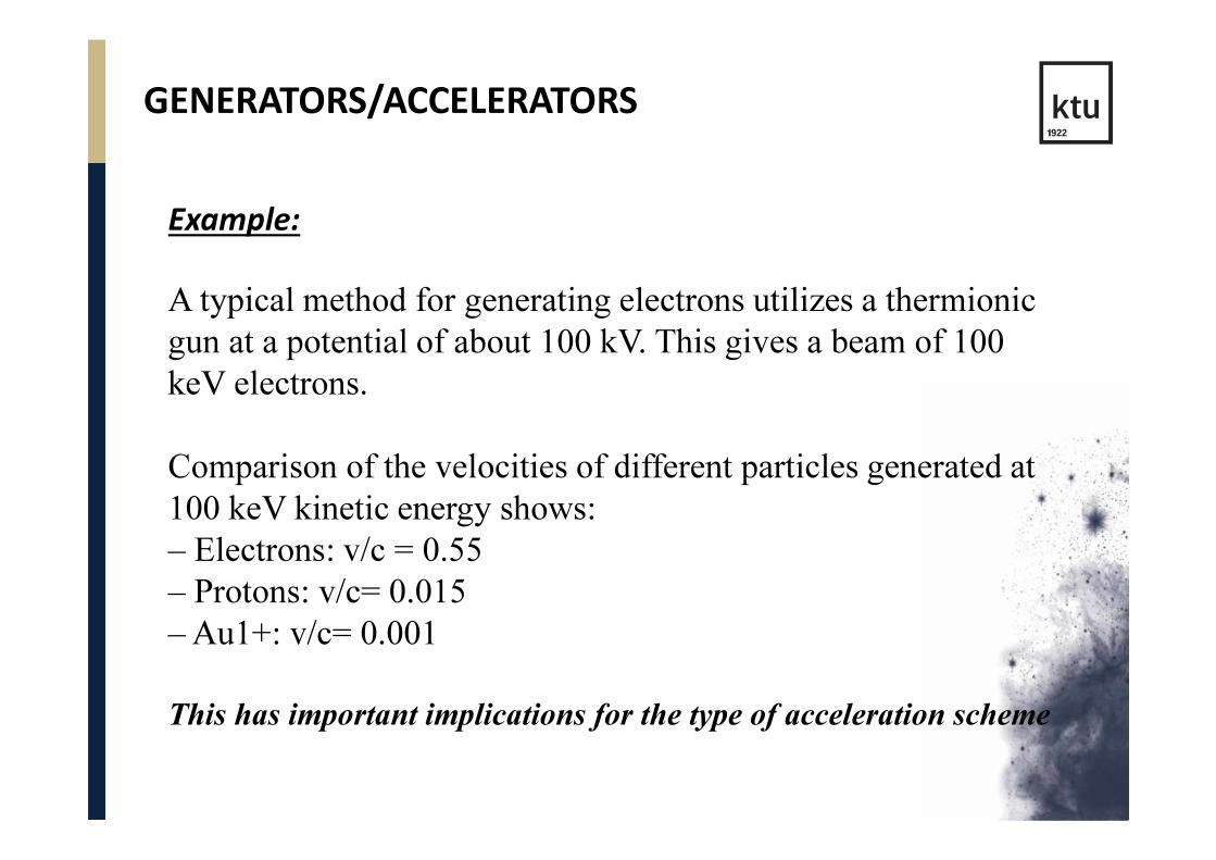
Example:
A typical method for generating electrons utilizes a thermionic
gun at a potential of about 100 kV. This gives a beam of 100
keV electrons.
Comparison of the velocities of different particles generated at
100 keV kinetic energy shows:
– Electrons: v/c = 0.55
– Protons: v/c= 0.015
– Au1+: v/c= 0.001
This has important implications for the type of acceleration scheme

PROTON AND ELECTRON VELOCITIES vs
KINETIC ENERGY

THE DEVELOPMENT OF ACCELERATORS
• Accelerators have gone through a long development process,
including
– Electrostatic accelerators
– The Van der Graaf accelerator
– The Cyclotron
– The Synchrotron

DIRECT ACCELERATORS:
TRANSFORMER TYPE
Direct accelerators are machines in which accelerated particle moves in a constant electric field gaining the energy (eV) which is equal to the potential difference (V) applied.
This applies for acceleration of electrons, protons and ions

Earliest particle accelerators/generators also called potential
drop generators were the Cockcroft- Walton generator and
the Van der Graaf generator
• Highest voltage achieved is 24 MV
• It is difficult to establish and maintain a static DC
field of 20+ MV
DIRECT ACCELERATORS:
TRANSFORMER TYPE

VAN DER GRAAF GENERATORS
• Van der Graaf generators
(electrostatic generators) are
direct accelerators.
• Generated energy is from the
range 0.5- 5.0 MeV
• Proton current 50 µA, in
pulses - 5 µA.
• Electrostatic generators are
energy stable, accelerated
particles are monoenergetic.

VAN DER GRAAF GENERATORS

VAN DER GRAAF GENERATOR
It was a hit !
Many labs could easily
obtain a Van der Graff.
- Low currents �
- High precision ☺

COCKCROFT-WALTON GENERATOR

COCKCROFT & WALTON GENERATOR
• The 1st stage of Fermilab’s huge accelerator is
a Cockcroft-Walton
Machine
• 750 keV
(Upper limit)

PARTICLE ACCELERATORS
• R. Widerøe (1929) proposed an accelerator by using an
alternating voltage across many alternating “gaps.”
• It was not without a myriad of problems
• - Focusing of beam
• - Vacuum leaks
• - Oscillating high voltages
• - Again, imagination
• His professor refused any further work because it was “sure to
fail.”
• - Widerøe still published his idea in Archiv fur Electrotechnic

ACCELERATION BY REPEATED
APPLICATION OF TIME-VARYING FIELDS
Ising and Widerøe suggested the repeated application of a much smaller
voltage in a linear accelerator by using time-varying fields
In this way, a high particle beam energy could be attained by repeatedly
applying voltage “kicks”
Ising‘s idea Widerøe or Sloan-Lawrence or
interdigital structure

SCHEMATIC OF WIDERØE’S LINAC

ACCELERATION TECHNIQUES: DC FIELD
• The simplest acceleration method: DC voltage
• Can accelerate particles over many gaps: electrostatic accelerator
• Problem: breakdown voltage at ~10MV
DC field still used at start of injector chain

ACCELERATION TECHNIQUES: RF FIELD
• Oscillating RF (radio-frequency) field
• Firstly introduced by Rolf Widerøe
(The principle is known as “Widerøe accelerator” untill now.)
• Particle must see the field only when the field is in the
accelerating direction
• Requires the synchronism condition to hold: Tparticle =½TRF
• Problem: high power loss due to radiation.
vTL )2/1(=

The particles gain energy by surfing on the electric fields
of well-timed radio oscillations
ACCELERATION TECHNIQUES: RF FIELD

ACCELERATION TECHNIQUES: RF CAVITIES
• Electromagnetic power is stored in a resonantvolume instead of being radiated;
• RF power feed into cavity, originating fromRF power generators, like Klystrons
• RF power oscillating (from magnetic toelectric energy), at the desired frequency
• RF cavities requires bunched beams (asopposite to coasting beams)
– particles located in bunches separated inspace

RADIOFREQUENCY POWER GENERATION SYSTEM
• The radiofrequency power
generation system produces
the microwave radiation used
in the accelerating waveguide
to accelerate electrons to the
desired kinetic energy and
consists of two major
components:
– RF power source
(magnetron or klystron)
– Pulsed modulator

FROM PILL-BOX TO REAL CAVITIES
LHC cavity module ILC cavity
(from A.
Chao)

ACCELERATION BY REPEATED APPLICATION OF TIME
VARYING ACCELERATING FIELDS
Two approaches for accelerating with time-varying fields:
an electric field along the direction of particle motion with Radio-
Frequency (RF) Cavities
Circular Accelerators
Use one or a small number of
Radiofrequency accelerating cavities
and make use of repeated passage
through them.
This approach leads to circular
accelerators: Cyclotrons, synchrotrons,
and their variants
Linear Accelerators
Use many accelerating cavities
through which the particle
passes only once
These are linear accelerators.

FROM LINEAR TO CIRCULAR ACCELERATORS?
• Technological limit on the electrical field in an RF cavity
(breakdown);
• Gives a limited ∆E per distance.
• ⇒ Circular accelerators, in order to re-use the same RF cavity
• This requires a bending field FB in order to follow a circular
trajectory

CIRCULAR ACCELERATORS
• Circular accelerators: deflecting forces are needed
• Circular accelerators: piecewise circular orbits with a defined bending
radius ρ
– Straight sections are needed for e.g. particle detectors
– In circular arc sections the magnetic field must provide
the desired bending radius:
• For a constant particle energy we need a constant B field ⇒ dipole magnets
with homogenous field.

SYNCHROTRON
In synchrotrons acceleration isperformed by RF cavities; particlesare accelerated along a closed,circular orbit and the magnetic fieldwhich bends the particles increaseswith time so that a constant orbit ismaintained during acceleration.
The bending field changes with particle beam energy to maintain a
constant radius, so B ramps in proportion to the momentum. The
revolution frequency also changes with momentum.

SYNCHROTRON
The synchrotron concept was first proposed in 1943 by the Australian
physicist Mark Oliphant.
• For an electron synchrotron, the injected beam is already
relativistic, so only the magnetic field changes with beam
energy.
• For a proton synchrotron, the injected beam is not yet
relativistic, so the RF accelerating frequency and the
magnetic field both ramp with energy• RF frequency must stay locked to the revolution
frequency of a particle
• Synchrotrons are used for most HEP experiments (LHC, Tevatron, HERA, LEP, SPS, PS)

STRONG-FOCUSING SYNCHROTRONS
There were two nearly identical very large proton
synchrotrons constructed at the same time 1959-1960:
At the European CERN laboratory
in Geneva (28 GeV)
At the Brookhaven National laboratory on
Long Island (33 GeV).
Both of them are still in operation.

SYNCHROTRON RADIATION
• Charged particles undergoing acceleration emit
electromagnetic radiation
• Main limitation for circular electron machines
– RF power consumption becomes too high
• The main limitation factor for LEP...
– ...the main reason for building LHC !
• However, synchrotron radiations is also useful

COLLIDERS
A collider can be thought of as a fixed-energy synchrotron.
Beams of matter and antimatter particles counter-rotate,
sharing the same beam pipe and are made to collide.
First electron-positron collider, ADA, at
Frascati which was built by Bruno
Touschek in 1960 (eventually reached 3
GeV)
The large hadron collider at
CERN (13 TeV)

LARGE HADRON COLLIDER
The evidence of Higgs boson
was experimentally aproved on
4.07.2012
Protons collide at 14 TeV in this
simulation from CMS,
producing four muons. Lines
denote other particles, and
energy deposited is shown in
blue15.07.2015 The LHCb experiment at
CERN’s Large Hadron Collider has
reported the discovery of a class of
particles known as pentaquarks

CYCLOTRON PRINCIPLE
Lawrence’s Application of Wideroe’s Idea: The Cyclotron
Uniform circular motion is
maintained via centripetal
acceleration:
The radius is:
Ernest Lawrence recognized that
the revolution period and
frequency are independent of
particle velocity:
Therefore, a particle in resonance
with a time varying field applied
to the Dees with frequency given
as above will be accelerated. The
particle is in synchronism with
the time-varying field.
• Such cylcotrons can accelerate
proton energies up to 20-30MeV

CYCLOTRON
• In a cyclotron the particles are accelerated along a spiral
trajectory guided inside two evacuated half-cylindrical
electrodes (dees) by a uniform magnetic field produced
between the pole pieces of a large magnet (1 T).

THE CYCLOTRON PRINCIPLE
� A vertical B-field provides the force to maintain the electron’s circular orbit
� The particles pass repeatedly from cavity to cavity, gaining energy.
� As the energy of the particles increases, the radius of the orbit increases until the particle is ejected

CYCLOTRON
– constant B field
– constant RF field in the gap increases energy
– radius increases proportionally to energy
– limit: relativistic energy, RF phase out of synch
– In some respects simpler than the synchrotron, and often used
as medical accelerators

THE FIRST MILLION VOLT CYCLOTRON
“... we were concerned about how many of the protons would succeed
in spiralling around a great many times without getting lost on the
way."
08/01/32
Lawrence and Livingston at Berkeley

PARTICLE ACCELERATORSBETATRON
• Betatron is a cyclic accelerator in which the electrons are made
to circulate in a toroidal vacuum chamber (doughnut) that is
placed into a gap between two magnet poles.
• Conceptually, the betatron may be considered an analog of a
transformer:
Primary current is the alternating current exciting the magnet.
Secondary current is the electron current circulating in the doughnut.

PARTICLE ACCELERATORSMICROTRON
• Microtron is an electron accelerator that combines the
features of a linac and a cyclotron.
• The electron gains energy from a resonant wave guide cavity
and describes circular orbits of increasing radius in a uniform
magnetic field.
• After each passage through the
wave guide the electrons gain an
energy increment resulting in a
larger radius for the next pass
through the wave guide cavity.

OTHER ACCELERATOR TYPES
Linear accelerators for linear colliders
-

LINEAR ACCELERATORS
Whereas a circular accelerator can make use of one or a small number of RF
accelerating cavities, a linear accelerator utilizes many (hundreds to thousands)
individual accelerating cells.
Again, accelerators for protons or ions “look” quite different from those that
accelerate electrons, because electron beams are already relativistic at low
energy.
Modern proton linear accelerators are based on the Alvarez Drift-Tube Linac.
Alvarez was awarded the 1968 Nobel Prize in Physics for his contributions to
elementary particle physics.
The two largest proton linear accelerators are the LANSCE linac at Los Alamos
(800 MeV) and the Spallation Neutron Source Linac at ORNL (1000 MeV).

LINEAR ACCELERATORS FOR
ELECTRONS
Most electron linacs utilize a structure
known as the Disk-Loaded Waveguide.
Geometry looks somewhat different from
that used for protons since electrons quickly
become relativistic

ACCELERATING CAVITIES
Modern machines use a time-dependent electric field in
a cavity to accelerate the particles

LINACS
Medical linacs are cyclic accelerators that accelerate electrons to
kinetic energies from 4 to 25 MeV using microwave
radiofrequency fields:
– 103 MHz : L band
– 2856 MHz: S band
– 104 MHz: X band
In a linac the electrons are accelerated following straight
trajectories in special evacuated structures called accelerating
waveguides.

LINACS
Schematic diagram of a modern fifth generation linac

LINACSINJECTION SYSTEM
Two types of electron gun producing electrons in linac:

LINACSACCELERATING WAVEGUIDE
Two types of accelerating waveguide are in use:
– Traveling wave structure
– Standing wave structure

ELECTRON
ACCELERATORS/IRRADIATORS
Direct
(transformer)
accelerator
Single cavity
accelerator
Linear
(microwave)
accelerator

DIRECT ACCELERATORS: TRANSFORMER TYPE
Capability for DC power supply (for transformer
accelerators)

Addopted from the lecture of dr. Z.Zimek (ICTJ)

• Single cavity accelerators


TYPES OF INDUSTRIAL IRRADIATORS
• Gamma-irradiators
�Sources:
mainly Co-60 and Cs-137
�Categorization:
from I to IV, specific design based on safety requirements
• Electron-beam irradiators
– Electron energy < 10 MeV
– also use of bremstrahlung

GAMMA IRRADIATORS: CO-60 SOURCE
• Activities ranging from 1 TBq to 100 PBq.
• Relatively long half-life of 5.26 years (source changing
frequency is minimised).
• Co in its solid form is insoluble and non-friable and has a high
melting point (1492 oC) - reduced risk of the spread of
radioactive contamination
beta minus decay with
emission of 2 high energy
gamma photons (1.17 MeV
and 1.33 MeV) beta
particles are absorbed in the
source capsule

GAMMA IRRADIATORS: CS-137 SOURCE
• Half life – 30.7 years.
• Caesium-137 has become less popular in recent years because
its solubility makes it more difficult to contain for long periods.
• It also emits lower energy which means that much larger
amounts of radioactive material are required to produce an
output equivalent to that from cobalt-60.
beta minus decay with
emission of gamma
photons (0.66 MeV, 0.036
MeV and 0.032 MeV)
beta particles are
absorbed in the source
capsule

TYPES OF GAMMA IRRADIATORS
• Category I
– self contained, dry storage irradiator
• Category II
– panoramic, dry storage irradiator
• Category III
– self contained, wet storage irradiator
• Category IV
– panoramic, wet storage irradiator

CATEGORY I
SELF-CONTAINED IRRADIATORS
• Sealed source (Co-60 or Cs-137) is mounted round a tube and
completely enclosed in a dry container constructed of solid
materials and is shielded (lead-steel containement )
• Activity – several Ci (1 Ci = 37 000 000 000 Bq)
• Applications:
• Preservation
(food, seeds, etc.)
• Radiation Effects
(biological research)
• Chemical synthesis
(chemical research)

Sources in here
(do not move)
Sample goes in here
Sample
lowered
CATEGORY I
SELF-CONTAINED IRRADIATORS

CATEGORY II
PANORAMIC SELF-CONTAINED IRRADIATORS
• A controlled human access irradiator in which the sealed
source (Co-60 or Cs-137) is enclosed in a dry container
constructed of solid materials, is fully shielded when not in use
and is exposed within a radiation volume that is maintained
inaccessible during use by an entry control system (maze,
concrete wals)
• Activity – several dozens of Ci
• Application:
• Sterilization (medical supplies)
• Preservation (food)

CATEGORY II
PANORAMIC SELF-CONTAINED IRRADIATORS
Open
Beam Port

CATEGORY III
SELF-CONTAINED WET STORAGE IRRADIATORS
• Sealed Co-60 source is
contained in a water filled
storage pool and is
shielded.
• Human access to the
sealed source and the
volume undergoing
irradiation is physically
restricted in the design
configuration.
• Activity – from several
hundreds to thousands of
CiSterilization (small medical supplies)

CATEGORY IV
SELF-CONTAINED WET STORAGE IRRADIATORS
A controlled human access
irradiator in which the
sealed Co-60 source is
contained in a water filled
storage pool, is fully
shielded when not in use
and is exposed within a
radiation volume that is
maintained inaccessible
during use by an entry
control systemSource rack
Activity – from dozens of thousands of Ci

CATEGORY IV
SELF-CONTAINED WET STORAGE IRRADIATORS
Co-60 source construction
Co-60 source pencil

Pencils
Rack
Source
Storage
CATEGORY IV
SELF-CONTAINED WET STORAGE IRRADIATORS

CATEGORY IV
SELF-CONTAINED WET STORAGE IRRADIATORS
• Water pool for storage
• Concrete walls and maze
during operation
Sterilization of big
packs with
medical suppliers,
pharmacy or
cosmetic products

ELECTRON BEAM IRRADIATORS (EBI)
• Beam energy up to 10 MeV
• Advantage – no induced
radioactivity
• Bremstrahlung from
electron beam interactions
with exposing items is
sometimes used but should
be protected
• Possibility of neutron
production should be taken
into account
Schematic view of electron generator

ELECTRON BEAM IRRADIATORS (EBI)
• Categorization
• Category I
– integrally shielded irradiator unit with interlocks
• Category II
– Irradiator unit housed in shielded room maintained
inaccessible during irradiation
• Applications• Preservation (food, caught fish, etc.)
• Sterilization
• Chemical synthesis (polymerization)

EBI: CATEGORY I
• An integrally shielded unit
with interlocks, where
human access during
operation is not physically
possible owing to the
configuration of the
shielding
• Concrete walls against
electrons and neutrons
• Some lead from
bremstrahlung,
• Aluminium for shielding
against electron beam

EBI: CATEGORY II
A unit housed in shielded rooms that are maintained inaccessible
during operation by an entry control system
– Concrete walls
– Maze for item supply

X-RAY MASCHINE
Forward Peaked Emission of
5.0 MeV X-rays

COMPARISON: BEAM PENETRATION
• The attractive features of X-ray processing for industrial applications,
Greater depth of penetration, allowing for treatment of products with large
volumes.
• Controllable dose rates, which can facilitate monomer polymerization.
• Not a thermal process which eliminates adverse effects on materials due to
the heat

COMPARISON: IONIZING RADIATION
SOURCES

X-RAY PROCESSING THROUGH-PUT
POTENTIAL

ENERGY EVOLUTION
Exponential growth of
energy with time
• Increase of the energy by an
order of magnitude every 6-10
years
• Each generation replaces
previous one to get even higher
energies.
• The process continues…
• Energy is not the only
interesting parameter.– Intensity
– Size of the beam

DEVELOPMENT IN RADIATION
PROCESSING
Continuous increase and development of irradiation facilities:
∼ 250 high activity 60Co gamma and ∼ 1000 EB machines (0.1 –
10 MeV).
Prospect for X-ray application.

NEW DEVELOPMENT IN RADIATION
PROCESSING EQUIPMENT

ADVANCED EB EMITER MODULE

LOW ENERGY EB ACCELERATOR

Diana Adlienė
Department of Physics
Kaunas University of Technology
4. Particle
Generators/Accelerators
Joint innovative training and teaching/
learning program in enhancing development
and transfer knowledge of application of
ionizing radiation in materials processing