Embed Size (px)
Citation preview
ANSI/ASHRAE Addendum a toANSI/ASHRAE Standard 140-2014
Standard Method of Testfor the Evaluation of
Building Energy AnalysisComputer Programs
Approved by ASHRAE on April 30, 2014, and by the American National Standards Institute on May 1, 2017.
This addendum was approved by a Standing Standard Project Committee (SSPC) for which the Standards Committee has estab-lished a documented program for regular publication of addenda or revisions, including procedures for timely, documented, con-sensus action on requests for change to any part of the standard. The change submittal form, instructions, and deadlines may beobtained in electronic form from the ASHRAE website (www.ashrae.org) or in paper form from the Senior Manager of Standards.
The latest edition of an ASHRAE Standard may be purchased on the ASHRAE website (www.ashrae.org) or from ASHRAE Cus-tomer Service, 1791 Tullie Circle, NE, Atlanta, GA 30329-2305. E-mail: [email protected]. Fax: 678-539-2129. Telephone: 404-636-8400 (worldwide), or toll free 1-800-527-4723 (for orders in US and Canada). For reprint permission, go towww.ashrae.org/permissions.
© 2017 ASHRAE ISSN 1041-2336
ASHRAE is a registered trademark of the American Society of Heating, Refrigerating and Air-Conditioning Engineers, Inc.ANSI is a registered trademark of the American National Standards Institute.
SPECIAL NOTEThis American National Standard (ANS) is a national voluntary consensus Standard developed under the auspices of ASHRAE. Consensus is definedby the American National Standards Institute (ANSI), of which ASHRAE is a member and which has approved this Standard as an ANS, as“substantial agreement reached by directly and materially affected interest categories. This signifies the concurrence of more than a simple majority,but not necessarily unanimity. Consensus requires that all views and objections be considered, and that an effort be made toward their resolution.”Compliance with this Standard is voluntary until and unless a legal jurisdiction makes compliance mandatory through legislation.
ASHRAE obtains consensus through participation of its national and international members, associated societies, and public review.ASHRAE Standards are prepared by a Project Committee appointed specifically for the purpose of writing the Standard. The Project
Committee Chair and Vice-Chair must be members of ASHRAE; while other committee members may or may not be ASHRAE members, allmust be technically qualified in the subject area of the Standard. Every effort is made to balance the concerned interests on all Project Committees.
The Senior Manager of Standards of ASHRAE should be contacted fora. interpretation of the contents of this Standard,b. participation in the next review of the Standard,c. offering constructive criticism for improving the Standard, ord. permission to reprint portions of the Standard.
DISCLAIMERASHRAE uses its best efforts to promulgate Standards and Guidelines for the benefit of the public in light of available information and acceptedindustry practices. However, ASHRAE does not guarantee, certify, or assure the safety or performance of any products, components, or systemstested, installed, or operated in accordance with ASHRAE’s Standards or Guidelines or that any tests conducted under its Standards or Guidelineswill be nonhazardous or free from risk.
ASHRAE INDUSTRIAL ADVERTISING POLICY ON STANDARDSASHRAE Standards and Guidelines are established to assist industry and the public by offering a uniform method of testing for rating purposes, bysuggesting safe practices in designing and installing equipment, by providing proper definitions of this equipment, and by providing other informationthat may serve to guide the industry. The creation of ASHRAE Standards and Guidelines is determined by the need for them, and conformanceto them is completely voluntary.
In referring to this Standard or Guideline and in marking of equipment and in advertising, no claim shall be made, either stated or implied,that the product has been approved by ASHRAE.
ASHRAE Standing Standard Project Committee 140Cognizant TC: 4.7, Energy Calculations
SPLS Liaison: Keith I. Emersom
Joel Neymark*, Chair Ronald Judkoff Eric Sturm*Drury B. Crawley* David E. Knebel* Michael J. Witte*Krishnan Gowri Timothy P. McDowell* Da Yan*Kamel Haddad James F. Pegues*Tianzhen Hong* Amir Roth*
* Denotes members of voting status when the document was approved for publication
ASHRAE STANDARDS COMMITTEE 2016–2017
Rita M. Harrold, Chair Michael W. Gallagher Cyrus H. NasseriSteven J. Emmerich, Vice-Chair Walter T. Grondzik David RobinJames D. Aswegan Vinod P. Gupta Peter SimmondsNiels Bidstrup Susanna S. Hanson Dennis A. StankeDonald M. Brundage Roger L. Hedrick Wayne H. Stoppelmoor, Jr.Drury B. Crawley Rick M. Heiden Jack H. ZarourJohn F. Dunlap, Srinivas Katipamula William F. Walter, BOD ExOJames W. Earley, Jr. Cesar L. Lim Patricia Graef, COKeith I. Emerson Arsen K. MelikovJulie M. Ferguson R. Lee Millies, Jr.
Stephanie C. Reiniche, Senior Manager of Standards
© ASHRAE (www.ashrae.org). For personal use only. Additional reproduction, distribution, or transmission in either print or digital form is not permitted without ASHRAE's prior written permission.
ANSI/ASHRAE Addendum a to ANSI/ASHRAE Standard 140-2014 1
(This foreword is not part of this standard. It is merely informative and does not contain requirements necessary for conformance to the standard. It has not been processed according to the ANSI requirements for a standard and may contain material that has not been subject to public review or a consensus process. Unresolved objectors on informative material are not offered the right to appeal at ASHRAE or ANSI.)
FOREWORD
The purpose of this addendum is to add a new set of cases, as new Section 5.5 of Standard 140, for testing the ability of whole-building energy simulation programs to model the air distribution side of typical heating, ventilating, and air-conditioning (HVAC) equipment. These cases test fundamental air-side system mass flow and heat balance modeling and are complementary to the current HVAC BESTEST and Furnace BESTEST cases of Sections 5.3 and 5.4, respectively, which test the ability to apply performance maps for modeling the working heat-transfer fluid side and combustion side of HVAC equipment. The new test cases are from Airside HVAC BESTEST: Adaptation of ASHRAE RP-865 Airside HVAC Equipment Modeling Test Cases for ASHRAE Standard 140, Volume 1: Cases AE101–AE445 A-5, by the National Renewable Energy Laboratory (NREL) in collaboration with the ASHRAE Standing Standard Project Committee 140 (SSPC 140) and other international software developers and simulation-trial participants. NREL’s adaptation work builds off of ASHRAE Research Project 865 (RP-865)A-7, conducted at University of Nebraska Omaha, The Pennsylvania State University, and Texas A&M University. General Description of the New Test Cases
The air-side HVAC equipment model test cases are steady-state analytical verification tests at a variety of constant zone and ambient conditions, where simulation results are compared to a vetted quasi-analytical solution that provides a secondary mathematical truth standard (see definitions in Section 3.1 of the standard) and may also be compared to other vetted example simulation results. The 24 test cases added here (summarized in Tables B1-9 through B1-16 of Informative Annex B1) are a revised subset of the cases and systems developed as part of RP-865. The test systems include the following: four-pipe fan coil (FC), single-zone air conditioner (SZ), constant-volume terminal reheat (CV), and variable-air-volume terminal reheat (VAV). The FC system is the simplest of the test-case systems: it is a single-zone system with heating and cooling coils, zone air exhaust, and limited outdoor air (no economizer control), and it does not include a return air fan. The FC system provides a good starting point for testing basic mass flow and heat balance modeling before addressing more complex air systems. In these test cases, the SZ system adds an economizer and a return air fan; the CV system further applies multiple (two) zones, system supply air temperature control, and terminal reheat coils; and the VAV system further applies a variable airflow supply fan and terminal zone supply air dampers. The test cases are conducted at five different sets of steady-state outdoor and zone conditions in heating, dry-coil cooling, and wet-coil cooling modes, and with temperature and enthalpy economizer outdoor air control strategies applied to selected conditions. Primary compared output for these test cases includes coil sensible, latent, and total loads; zone sensible and latent loads; and cooling-coil leaving-air relative humidity. Additional diagnostic outputs at various points in the systems include dry-bulb temperature (and the ability to isolate fan heat effects), humidity ratio, specific volume, enthalpy, and mass flow rate. For these in-depth cases, plant energy use related to coil loads and fan electricity consumption is not considered. Adaptation of ASHRAE RP-865 as a Standard Method of Test
The air-side HVAC equipment model test cases are an excellent example of ASHRAE research providing the kernel, in this instance RP-865 A-7, for an industry-standard method of test. RP-865 developed a test specification, and two independently developed spreadsheet solutions, intended as quasi-analytical solutions for a number of typical air-side HVAC system configurations, such as constant-volume and variable-air-volume reheat systems. At the time RP-865 was developed, the scope for input descriptions in its test specification was limited to two prominent whole-building energy simulation programs. NREL led the collaborative effort by SSPC 140 and other international software developers and participants to (a) reconcile differences in the two analytical solutions to produce a single, final quasi-analytical solution, (b) rework the test specifications to be unambiguous for the input structures of most whole-building energy simulation programs with time steps of one hour or less, and (c) field test the specifications with a variety of different simulation programs and associated international software development groups to ensure their suitability as a standard method of test that can be integrated into ASHRAE Standard 140. Further discussion of the
© ASHRAE (www.ashrae.org). For personal use only. Additional reproduction, distribution, or transmission in either print or digital form is not permitted without ASHRAE's prior written permission.
2 ANSI/ASHRAE Addendum a to ANSI/ASHRAE Standard 140-2014
process for revising the test specifications and developing the final quasi-analytical solutions and example simulation results is provided in the Executive Summary, Part II, and Part III of the Airside HVAC BESTEST final report A-5. Summary of Changes in this Addendum
• Adds new Section 5.5, “Input Specification for Air-Side HVAC Equipment Analytical Verification Tests.” (This is the major substantive portion of the addendum.)
• Updates Section 6, “Class I Output Requirements,” to include output requirements related to Section 5.5. • Updates Section 3, “Definitions, Abbreviations, and Acronyms” for language of Section 5.5. • Updates Section 4, “Methods of Testing” (overall Standard 140 roadmap), to summarize new Section 5.5
test cases. • Updates Section 5.1, “Modeling Approach,” to include requirements related to Section 5.5. • Updates Normative Annex A1, “Weather Data,” to include weather data used for Section 5.5. • Updates Normative Annex A2, “Standard Output Reports,” to include Section 5.5 results template. • Updates the following informative annexes to include new information relevant for Section 5.5 test cases:
o B1, “Tabular Summary of Test Cases” o B10, “Instructions for Working with Results Spreadsheets Provided with the Standard” o B16, “Analytical and Quasi-Analytical Solution Results and Example Simulation Results for HVAC
Equipment Performance Tests of Sections 5.3, 5.4, and 5.5” o B17, “Production of Analytical and Quasi-Analytical Solution Results and Example Simulation
Results for HVAC Equipment Performance Tests of Sections 5.3, 5.4, and 5.5” o B20, “Example Results for Section 7 Test Procedures” (to provide editorial cross-referencing
changes) o B24, “Informative References”
• Updates accompanying electronic files as referenced in this addendum
© ASHRAE (www.ashrae.org). For personal use only. Additional reproduction, distribution, or transmission in either print or digital form is not permitted without ASHRAE's prior written permission.
ANSI/ASHRAE Addendum a to ANSI/ASHRAE Standard 140-2014 3
Addendum a to Standard 140-2014 Make the following changes to Section 3.1. 3.1 Terms Defined for This Standard adiabatic: without loss or gain of heat. Informative Note: (eE.g., an adiabatic boundary does not allow heat to flow through it). altitude: vertical elevation above sea level. apparatus dew point (ADP): the effective coil surface temperature when there is dehumidification. On the psychrometric chart, this is the intersection of the condition line and the saturation curve, where the condition line is the line going through entering air conditions with slope defined by the sensible heat ratio (SHR) [ratio of sensible heat transfer to total (sensible + latent) heat transfer for a process]. For the test cases of Section 5.3, SHR is calculated as SHR = ([gross sensible capacity])/([gross total capacity]). (Also sSee sensible heat ratio, gross sensible capacity, and gross total capacity.) Informative Note: The ADP is the temperature to which all the supply air would be cooled if 100% of the supply air contacted the coil. bypass factor (BF): the percentage of the distribution air that does not come into contact with the cooling coil; the remaining air is assumed to exit the coil at the average coil temperature (apparatus dew point). (See apparatus dew point.) combined radiative and convective surface coefficient: a constant of proportionality relating the rate of combined convective and radiative heat transfer at a surface to the temperature difference across the air film on that surface. combined surface coefficient: see combined radiative and convective surface coefficient. conductance: thermal conductance. convective surface coefficient: a constant of proportionality relating the rate of convective heat transfer at a surface to the temperature difference across the air film on that surface. cooling-coil latent load: the rate of heat extraction required to condense the moisture in cooling-coil entering air that becomes condensate. Informative Note: For example equation, see the 2012 ASHRAE Handbook—HVAC Systems and Equipment A-1, Chapter 23, Equation 38. cooling-coil sensible load: the sum of the rate of heat extraction required to
• cool the leaving moist air mass from the cooling-coil entering air temperature to the cooling-coil leaving air temperature,
• cool any to-be-condensed vapor from the cooling-coil entering air temperature to the condensation temperature, and
• cool any condensate from the condensation temperature to the leaving condensate temperature. Informative Note: For example equations, see the 2012 ASHRAE Handbook—HVAC Systems and Equipment,A-1 Chapter 23, Equations 39 and 39a. cooling-coil total load: the sum of cooling-coil sensible load and cooling-coil latent load. Informative Note: For example equations, see the 2012 ASHRAE Handbook—HVAC Systems and Equipment,A-1 Chapter 23, Equations 36 and 37. design nominal zone supply airflow rate: the maximum zone supply volumetric airflow rate using air conditions at the supply fan inlet. Informative Note: The actual design zone supply air volumetric flow varies as supply fan heat and terminal reheat increase the specific volume of the air away from the supply fan inlet.
© ASHRAE (www.ashrae.org). For personal use only. Additional reproduction, distribution, or transmission in either print or digital form is not permitted without ASHRAE's prior written permission.
4 ANSI/ASHRAE Addendum a to ANSI/ASHRAE Standard 140-2014
design system return airflow rate: the volumetric return airflow rate calculated from the design system supply airflow rate minus the total zone exhaust airflow rates for the defined zones). This is the volumetric airflow rate at which the return fan pressure rise is specified. Informative Note: The actual return fan volumetric flow varies with the return air mass flow and the specific volume of the air entering the return fan. design system supply airflow rate: the maximum system supply volumetric airflow rate at the supply fan inlet. This is the volumetric airflow rate at which the supply fan pressure rise is specified for the VAV system. Informative Note: In a VAV system, the supply fan volumetric flow varies to meet the zone terminal airflow requirements. dew-point temperature: the temperature of saturated air at a given humidity ratio and pressure. As moist air is cooled at constant pressure, the dew point is the temperature at which condensation begins. temperature at which water vapor has reached the saturation point (100% relative humidity; see relative humidity); temperature of the air at which it must be cooled at constant barometric pressure for water vapor to condense. (Also see humidity ratio.) economizer: a control system that conserves energy., usually by using outdoor air and control logic to maintain a fixed minimum of outdoor air when increased outdoor airflow rates are not called for. For Standard 140, this is a control system designed to conserve cooling energy by increasing outdoor airflow above minimum ventilation requirements when control logic indicates that using more outdoor air will reduce or eliminate cooling-coil loads. fan mechanical efficiency (fan total efficiency [ηt]): ηt = Ho/Hi, where
Ho = Q × Pt × Kp × C; this is the fan power output (causing airflow and pressure rise), W (hp), where Q = fan airflow rate, m3/s (cfm) Pt = fan total pressure rise, Pa (in. of water); fan total pressure rise includes static pressure (from
compression) and velocity pressure (from rate of motion)
Kp = compressibility coefficient (dimensionless). Informative Note: For fan total pressure < 12 in. of water, Kp is usually greater than 0.99 and may be taken as unity A-2.
C = units conversion constant. Informative Note: For Système Internationale (SI) units, C = 1; for inch-pound (I-P) units, C may be taken as approximately 1/6343.3 per the literature A-3.
Hi = fan power input, W (hp). This is also called “power input to impeller” or “shaft power input” and is the remaining mechanical power after subtracting fan motor and transmission drive power losses from the fan motor input power (see motor efficiency and transmission drive efficiency). Informative Note: This parameter is designated as Wsh in Informative Annex B15.
Informative Note: Fan total efficiency and related terminology are further described in the literature A-3,A-4. gross sensible capacity: the rate of sensible heat removal by the cooling coil for a given set of operating conditions. (Also sSee sensible heat.) Informative Note: This value varies as a function of performance parameters such as EWB, ODB, EDB, and airflow rate. gross total capacity: the total rate of both sensible heat and latent heat removal by the cooling coil for a given set of operating conditions. (Also sSee sensible heat and latent heat.) Informative Note: This value varies as a function of performance parameters such as EWB, ODB, EDB, and airflow rate. heating-coil load: the rate of heat addition required to heat the moist air mass entering the heating coil from the heating-coil entering air temperature to the heating-coil leaving air temperature. humidity ratio: the ratio of the mass of water vapor to the mass of dry air in a moist air sample. indoor dry-bulb temperature (IDB): the temperature indicated by an ordinary thermometer when exposed to indoor air. infiltration: the leakage of air through any building element. Informative Note: (eE.g., air leakage through walls, windows, and/or doors). infrared emittance: the ratio of the infrared spectrum radiant flux emitted by a body to that emitted by a blackbody at the same temperature and under the same conditions.
© ASHRAE (www.ashrae.org). For personal use only. Additional reproduction, distribution, or transmission in either print or digital form is not permitted without ASHRAE's prior written permission.
ANSI/ASHRAE Addendum a to ANSI/ASHRAE Standard 140-2014 5
internal gains: the heat gains generated inside the space or zone. latent heat: the change in enthalpy associated with a change in humidity ratio, caused by the addition or removal of moisture. (Also sSee humidity ratio.) motor efficiency (ηm):
ηm = Hm/He, where Hm = usable motor shaft output power, W (hp) He = motor electric input power, W (hp). Informative Note: This parameter is designated as W in Informative
Annex B15. nominal zone supply airflow rate: the zone supply volumetric airflow rate calculated using conditions of the air at the supply fan inlet. Informative Note: The actual zone supply air volumetric flow rate varies as supply fan heat and terminal reheat increase the specific volume of the air away from the supply fan inlet. nonproportional-type thermostat: a thermostat that provides two position (ON/OFF) control. outdoor dry-bulb temperature (ODB): the temperature indicated by an ordinary thermometer when exposed to outdoor air. Informative Note: For the test cases of Section 5.3, Tthis is the temperature of air entering the condenser coil. preheat-coil load: the rate of heat addition required to heat the moist air mass entering the preheat coil from the preheat-coil entering air temperature to the preheat-coil leaving air temperature. quasi-analytical solution: the mathematical solution of a model for a given set of parameters and simplifying assumptions; , which such a solution is allowed to include minor interpretation differences that cause minor results variations. Informative Note: Such a solution may be computed by generally accepted numerical methods or other means, provided that such calculations occur outside the environment of a whole-building energy simulation program and can be scrutinized. reheat-coil load: for a given zone reheat coil, the rate of heat addition required to heat the given zone supply air moist air mass from the system supply air temperature to the zone supply air temperature for the given zone. relative humidity: (a) the ratio of the mole fraction of water vapor in a given moist air sample to the mole fraction in an air sample that is saturated and at the same temperature and pressure or This is equivalent to (b) the ratio of partial pressure of the water vapor in a sample to the saturation pressure at the same dry-bulb temperature and barometric pressure of the ambient air. sensible heat: the change in enthalpy associated with a change in dry-bulb temperature caused by the addition or removal of heat. sensible heat ratio (SHR): the ratio of sensible heat transfer to total (sensible + latent) heat transfer for a process; also alternatively known as sensible heat factor (SHF). (Also sSee sensible heat and latent heat.) system supply airflow rate: the volumetric airflow rate measured at the supply fan inlet. Informative Note: As the temperature and humidity ratio of the air entering the supply fan change, the specific volume of that air changes; this means that for a given supply volumetric airflow rate, the mass flow rate of supply air varies among the Section 5.5 test cases. transmission drive efficiency (ηd):
ηd = Hi/Hm, where Hi = fan power input, W (hp); see Hi under fan mechanical efficiency. Hm = usable motor shaft output power, W (hp).
Informative Note: Fan motor shaft power is typically transferred to the fan impeller using belts or direct drive.
© ASHRAE (www.ashrae.org). For personal use only. Additional reproduction, distribution, or transmission in either print or digital form is not permitted without ASHRAE's prior written permission.
6 ANSI/ASHRAE Addendum a to ANSI/ASHRAE Standard 140-2014
zone air temperature: the temperature of just the zone air, not including infrared radiation from the interior surfaces. Informative Note: Such a temperature would be measured by a sensor housed in a well-aspirated containment shielded by a material with a solar and infrared reflectance of one; well mixed air is assumed. zone exhaust airflow rate: the volumetric airflow rate measured at the inlet of a given zone’s exhaust fan. Informative Note: As the temperature and humidity ratio of the air entering an exhaust fan change, the specific volume of that air changes; this means that for a given exhaust volumetric airflow rate, the mass flow rate of exhaust air from each zone varies among the Section 5.5 test cases. zone latent load: for the test cases of Section 5.5, the rate of heat addition to vaporize the water added to the zone at a temperature of 0° in the units system used (SI or I-P), plus the energy required to heat that added vapor from 0° to the zone temperature. Informative Note: This definition may be expressed as shown in equation form below (also see Part II, Section 2.2.1.8 of the originating test suite adaptation reportA-5).
Zone latent load = [mass of moisture added to zone, kg/s (lb/h)] × [i0,water vapor + Cpwater vapor × Tzone], where i0,water vapor = specific enthalpy of water vapor at zero degrees, kJ/kg (Btu/lb) Cpwater vapor = specific heat of water vapor, kJ/(kg·K) (Btu/[lb·°F]) Tzone = zone air temperature, °C (°F).
In the above equation, “[i0,water vapor + Cpwater vapor × Tzone]” equals the enthalpy of water vapor ig at the given zone temperature based on ideal gas laws. This approximates the real-gas model values listed in the 2009 ASHRAE Handbook—Fundamentals A-6, Chapter 1, Table 3.
zone sensible cooling load: for the test cases of Section 5.5, the rate at which sensible heat must be extracted from the zone to maintain the zone air temperature setpoint. Informative Note: This definition may be expressed as shown in equation form below based on ASHRAE RP-865 A-7.
Zone sensible cooling load = [dry air mass flow rate, kg/s (lb/h)] × [(Tzone – Tsupply) × (Cpair + Cpwater vapor × Wsupply)], where Tzone = zone air temperature, °C (°F) Tsupply = zone supply air temperature, °C (°F); for the FC and SZ systems this is the same as the system supply
air temperature Cpair = specific heat of dry air, kJ/(kg·K) (Btu/[lb·°F]) Cpwater vapor = specific heat of water vapor, kJ/(kg·K) (Btu/[lb·°F]) Wsupply = zone supply air humidity ratio (kg water vapor)/(kg dry air) ([lb water vapor]/[lb dry air]); for the
FC and SZ systems, this is the same as the system supply air humidity ratio. zone sensible heating load: for the test cases of Section 5.5, the rate at which sensible heat must be added to the zone to maintain the zone air temperature setpoint. Informative Note: This definition may be expressed as shown in equation form below based on ASHRAE RP 865A-7.
Zone sensible heating load = [dry air mass flow rate, kg/s (lb/h)] × [(Tsupply – Tzone) × (Cpair + Cpwater vapor × Wsupply)], where Tsupply = zone supply air temperature, °C (°F); for the FC and SZ systems, this is the same as the system supply
air temperature Tzone = zone air temperature, °C (°F) Cpair = specific heat of dry air, kJ/(kg·K) (Btu/[lb·°F]) Cpwater vapor = specific heat of water vapor, kJ/(kg·K) (Btu/[lb·°F]) Wsupply = zone supply air humidity ratio ratio (kg water vapor)/(kg dry air) ([lb water vapor]/[lb dry air]); for
the FC and SZ systems, this is the same as the system supply air humidity ratio. zone supply air mass flow fraction: the fraction of system supply air mass flow distributed to each zone.
© ASHRAE (www.ashrae.org). For personal use only. Additional reproduction, distribution, or transmission in either print or digital form is not permitted without ASHRAE's prior written permission.
ANSI/ASHRAE Addendum a to ANSI/ASHRAE Standard 140-2014 7
Add the following abbreviations to Section 3.2 relevant to new language of Addendum A. 3.2 Abbreviations and Acronyms Used in This Standard ADP apparatus dew point AMCA Air Movement and Control Association International, Inc. ANSI American National Standards Institute ASHRAE American Society of Heating, Refrigerating and Air-Conditioning Engineers BESTEST Building Energy Simulation Test and Diagnostic Method BF bypass factor cfm cubic feet per minute Coef. coefficient cp specific heat, J/(kg·K) [Btu/(lb·°F)] CV constant-volume terminal reheat system, see Section 5.5.3 DOE United States Department of Energy EDB entering dry-bulb temperature EWB entering wet-bulb temperature Ext. exterior FC four-pipe fan-coil system, see Section 5.5.1 Ho fan output power required to meet specified airflow requirements HVAC heating, ventilating, and air conditioning HVAC BESTEST International Energy Agency Building Energy Simulation Test and Diagnostic Method for
Heating, Ventilating, and Air-Conditioning Equipment Models IDB indoor dry-bulb temperature Int interior I-P inch-pound NREL National Renewable Energy Laboratory Num. number OAE outdoor air enthalpy ODB outdoor dry-bulb temperature ODBecono,min the outdoor dry-bulb temperature where at the minimum required outdoor airflow rate Tzone =
zone thermostat setpoint ODP outdoor dew-point temperature QAS quasi-analytical solution QCsensible system cooling-coil sensible load, kWh/h QClatent system cooling-coil latent load, kWh/h QCtotal system cooling-coil total load, QCsensible + QClatent, kWh/h QH system heating-coil load, kWh/h; used for single-zone (FC and SZ) system test cases QHpreheat system preheat-coil load, kWh/h QH1reheat reheat-coil load: Zone 1, kWh/h QH2reheat reheat-coil load: Zone 2, kWh/h QZHsensible zone sensible heating load, kWh/h; used for single-zone (FC and SZ) system test cases QZCsensible zone sensible cooling load, kWh/h; used for single-zone (FC and SZ) system test cases QZlatent zone latent load, kWh/h; used for single-zone (FC and SZ) system test cases QZH1sensible Zone 1 sensible heating load, kWh/h QZC1sensible Zone 1 sensible cooling load, kWh/h QZ1latent Zone 1 latent load, kWh/h QZH2sensible Zone 2 sensible heating load, kWh/h QZC2sensible Zone 2 sensible cooling load, kWh/h QZ2latent Zone 2 latent zone load, kWh/h R unit thermal resistance, m2·K/W [h·ft2·°F/Btu] RAE return air enthalpy RAT return air temperature RHcco cooling-coil leaving air relative humidity, % SAT supply air temperature SFEAT supply fan entering air temperature
© ASHRAE (www.ashrae.org). For personal use only. Additional reproduction, distribution, or transmission in either print or digital form is not permitted without ASHRAE's prior written permission.
8 ANSI/ASHRAE Addendum a to ANSI/ASHRAE Standard 140-2014
SHR sensible heat ratio SI Système Internationale SSPC 140 ASHRAE Standing Standard Project Committee responsible for ANSI/ASHRAE Standard 140,
Standard Method of Test for the Evaluation of Building Energy Analysis Computer Programs Surf. surface SZ single-zone system; see Section 5.5.2 TMY2 or TM2 Typical Meteorological Year 2 Tsupply dry-bulb temperature of the zone supply air, °C Tzone dry-bulb temperature of the zone air temperature, °C U unit thermal conductance or overall heat transfer coefficient, W/(m2·K) [Btu/(h·ft2·°F)] UA thermal conductance, W/K VAV variable-air-volume terminal reheat system, see Section 5.5.4 w.g. water gage Wsupply humidity ratio of the zone supply air, (kg vapor)/(kg dry air) Wzone humidity ratio of the zone air, (kg vapor)/(kg dry air) Subscripts cco system location, cooling-coil outlet hco system location, heating-coil outlet ma system location, mixed air (recirculated and outdoor) before coils and supply fan oa system location, outdoor air inlet pco system location, preheating coil outlet ra system location, return air rfi system location, return fan inlet rfo system location, return fan outlet sa system location, supply fan outlet (system supply air to zones) z1 Zone 1 air z1s system location, supply air to Zone 1 after terminal reheat-coil z2 Zone 2 air z2s system location, supply air to Zone 2 after terminal reheat-coil
© ASHRAE (www.ashrae.org). For personal use only. Additional reproduction, distribution, or transmission in either print or digital form is not permitted without ASHRAE's prior written permission.
ANSI/ASHRAE Addendum a to ANSI/ASHRAE Standard 140-2014 9
Revise Section 4 as shown; only the Section 4 material with changes is shown here. Changes include reference to the new test cases of Section 5.5 and related editorial revisions. 4. METHODS OF TESTING Add air-side HVAC equipment analytical verification tests to Class I test procedures listing (4.3.a.5) as shown. 4.3 Organization of Test Cases (a) Class I test procedures
5. Air-side HVAC Equipment Analytical Verification Test Cases (see Section 4.3.1.5) • Four-Pipe Fan-Coil (FC) System Cases (see Section 4.3.1.5.1) • Single-Zone (SZ) System Cases (see Section 4.3.1.5.2) • Constant-Volume Terminal Reheat (CV) System Cases (see Section 4.3.1.5.3) • Variable-Air-Volume Terminal Reheat (VAV) System Cases (see Section 4.3.1.5.4)
Add new Section 4.3.1.5. 4.3.1.5 Air-Side HVAC Equipment Analytical Verification Tests. These test cases, presented in detail in Section 5.5, are designed to test the ability to model HVAC air distribution system equipment. The cases complement the test cases of Section 5.3, which test the ability to model the working-fluid side of HVAC equipment (also see Sections 4.3.1.2 and 4.3.1.3), and the test cases of Section 5.4, which test the ability to model space heating equipment performance (also see Section 4.3.1.4). Four systems are tested as described in the following subsections. 4.3.1.5.1 Four-Pipe Fan-Coil (FC) System. This is the most simple of the test systems. It is a single-zone system with heating and cooling coils, zone air exhaust, and limited outdoor air (no economizer control), and it does not include a return air fan. The FC system provides a good starting point for testing basic mass flow and heat balance modeling before addressing more complex air systems. The FC system tests include three sets of steady-state outdoor and zone conditions in heating, dry-coil cooling, and wet-coil cooling modes. The FC system cases are presented in detail in Section 5.5.1. 4.3.1.5.2 Single-Zone (SZ) System. The SZ system is based on the FC system but adds a return air fan and economizer outdoor air control. The SZ system tests include five sets of steady-state outdoor and zone conditions in heating, dry-coil cooling, and wet-coil cooling modes, and with temperature and enthalpy economizer outdoor air control strategies applied to selected conditions. The SZ system cases are presented in detail in Section 5.5.2. 4.3.1.5.3 Constant-Volume Terminal Reheat (CV) System. The CV system is based on the SZ system, but adds multiple (two) zones, system supply air temperature control, and terminal reheat coils. The five sets of CV system test-case conditions are the same as those for the SZ system but applying different zone load and temperature setpoint parameters for the second zone. The CV system cases are presented in detail in Section 5.5.3. 4.3.1.5.4 Variable-Air-Volume Terminal Reheat (VAV) System. The VAV system is based on the CV system but applies a variable airflow supply fan and terminal zone supply air dampers (along with terminal reheat coils). The VAV system test-case conditions are the same as those for the CV system. The VAV system cases are presented in detail in Section 5.5.4.
© ASHRAE (www.ashrae.org). For personal use only. Additional reproduction, distribution, or transmission in either print or digital form is not permitted without ASHRAE's prior written permission.
10 ANSI/ASHRAE Addendum a to ANSI/ASHRAE Standard 140-2014
Revise Section 4.4 as shown. 4.4 Comparing Output to Other Results. For Class I test procedures, a. Informative Annex B8, Section B8.1, gives example simulation results for the building thermal envelope and fabric
load tests of Sections 5.2.1, 5.2.2, and 5.2.3; b. Informative Annex B8, Section B8.2, gives analytical solution, verified numerical model, and example simulation
results for the ground-coupled slab-on-grade tests of Section 5.2.4. c. Informative Annex B16 gives quasi-analytical solution results and example simulation results for the HVAC
equipment performance tests of Sections 5.3, 5.4, and 5.5.4. For Class II test procedures (See Section 7), Informative Annex B20 gives example simulation results. The user may choose to compare output with the example results provided in Informative Annexes B8, B16, and B20 or with other results that were generated using this standard method of test (including self-generated quasi-analytical solutions related to cases where such solutions are provided). For Class I test procedures, information about how the example results were produced is included in Informative Annex B11 for building thermal envelope and fabric load and ground-coupled slab-on-grade tests, and in Informative Annex B17 for HVAC equipment performance tests. For Class II test procedures, information about how the example results were produced is included in Informative Annex B21. For the convenience of users who wish to plot or tabulate their results along with the example results, electronic versions of the example results are included with the accompanying electronic media: for Informative Annex B8 with the files RESULTS5-2A.XLS and RESULTS5-2B.XLSX; for Informative Annex B16 with the files RESULTS5-3A.XLS, RESULTS5-3B.XLS, and RESULTS5-4.XLS, RESULTS5-5FCSZ.XLSX, and RESULTS5-5CVVV.XLSX; and for Informative Annex B20 with the file RESULTS7-2.XLS. Documentation for navigating these results files is included on the accompanying electronic media and is printed in Informative Annex B10.
© ASHRAE (www.ashrae.org). For personal use only. Additional reproduction, distribution, or transmission in either print or digital form is not permitted without ASHRAE's prior written permission.
ANSI/ASHRAE Addendum a to ANSI/ASHRAE Standard 140-2014 11
Revise Sections 5.1, 5.1.2, 5.1.3, and 5.1.7, and add Section 5.1.8.5 as shown. 5.1 Modeling Approach. This modeling approach shall apply to all the test cases presented in Sections 5..2, 5.3,
and 5.4. 5.1.2 Geometry Convention. If the program being tested includes the thickness of walls in a three-dimensional
(3D) definition of the building geometry, then wall, roof, and floor thicknesses shall be defined such that the interior air volume of the building model remains as specified. The thicknesses shall extend exterior to the currently defined internal volume. Informative Note: (eE.g., for the building thermal envelope and fabric load test cases of Sections 5.2.1, 5.2.2, and 5.2.3, interior air volume would be calculated as 6 × 8 × 2.7 m = 129.6 m3 [19.7 × 26.2 × 8.9 ft = 4576.8 ft3]).
5.1.3 Nonapplicable Inputs. In some instances If the specification will includes input values that do not apply to
the input structure of the program being tested,. When this occurs, disregard the nonapplicable inputs and continue. Informative Note: Selected equivalent inputs are included in the test specification for those programs that may need
them. 5.1.7 Simulation Initialization and Preconditioning. If the program being tested allows, the simulation
initialization process shall begin with zone air conditions that equal the outdoor air conditions. If the program being tested allows for preconditioning (iterative simulation of an initial time period until temperatures, or fluxes, or loads, or bothall of these, stabilize at initial values), that capability shall be used. If the program being tested allows, and if applicable to the model, the simulation initialization process shall begin with zone air conditions that equal the outdoor air conditions.
5.1.8.5 For the tests of Section 5.5, the simulation shall be run until the final hour output agrees with the previous
hour output. Provide output in accordance with Section 6.5.
© ASHRAE (www.ashrae.org). For personal use only. Additional reproduction, distribution, or transmission in either print or digital form is not permitted without ASHRAE's prior written permission.
12 ANSI/ASHRAE Addendum a to ANSI/ASHRAE Standard 140-2014
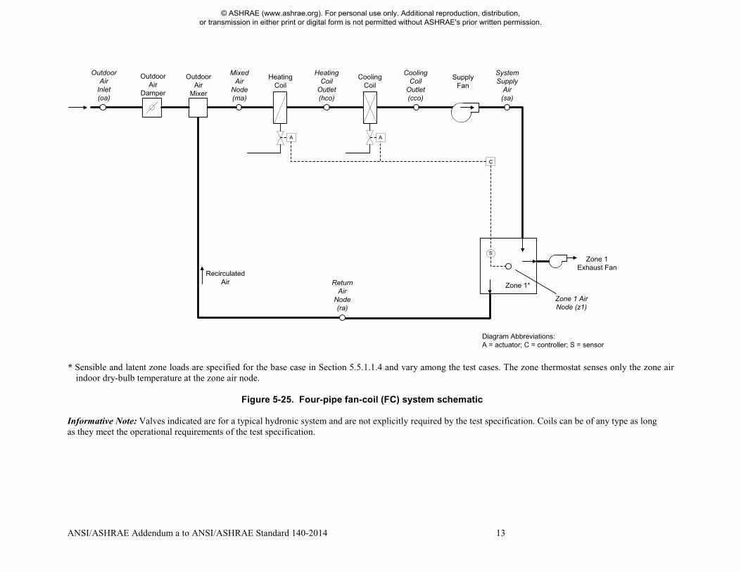
Add new Section 5.5. 5.5 Input Specification for Air-Side HVAC Equipment Analytical Verification Tests 5.5.1 Four-Pipe Fan-Coil (FC) System Cases (AE100 Series) The ability to model a four-pipe fan-coil (FC) system shall be tested as described in this section. Informative Note: If the software being tested is capable of applying a variety of system models to address an FC system, the system model that is most similar to the FC system specified for Case AE101 below should be applied, and the same selected system should be applied for all of the FC system test cases. The user may test other possible modeling approaches (available system models) in this context as appropriate to the software being tested. 5.5.1.1 Case AE101: Base Case, High-Heating 1 Case AE101 shall be modeled as described in this section and its subsections. The system configuration shall be modeled as presented in the schematic diagram in Figure 5-25. System input parameters shall be as described in the following sections. Informative Note, Objective of the Test Case: Test model treatment of a four-pipe fan-coil air system with high sensible heating load and cold outdoor air. Informative Note, Method of the Test Case: An FC air system with a constant-volume supply fan and heating and cooling coils conditions a single zone that has constant sensible and latent internal loads. The model is run at specified constant outdoor and indoor conditions. Resulting coil loads are compared with the quasi-analytical solution (QAS) and with other example results (see Informative Annex B16, Section B16.7). The QAS is provided with the accompanying electronic media and is further discussed in Informative Annex B17, Section B17.3.
© ASHRAE (www.ashrae.org). For personal use only. Additional reproduction, distribution, or transmission in either print or digital form is not permitted without ASHRAE's prior written permission.
ANSI/ASHRAE Addendum a to ANSI/ASHRAE Standard 140-2014 13
* Sensible and latent zone loads are specified for the base case in Section 5.5.1.1.4 and vary among the test cases. The zone thermostat senses only the zone air
indoor dry-bulb temperature at the zone air node.
Figure 5-25. Four-pipe fan-coil (FC) system schematic
Informative Note: Valves indicated are for a typical hydronic system and are not explicitly required by the test specification. Coils can be of any type as long as they meet the operational requirements of the test specification.
HeatingCoil
Cooling Coil
Supply Fan
Zone 1*
c
A A
Outdoor Air
Inlet(oa)
Mixed Air
Node(ma)
HeatingCoil
Outlet(hco)
Cooling Coil
Outlet(cco)
SystemSupply
Air(sa)
Zone 1 Exhaust Fan
Recirculated Air
Zone 1 Air Node (z1)
Outdoor Air
Damper
S
Outdoor Air
Mixer
Return Air
Node(ra)
Diagram Abbreviations: A = actuator; C = controller; S = sensor
© ASHRAE (www.ashrae.org). For personal use only. Additional reproduction, distribution, or transmission in either print or digital form is not permitted without ASHRAE's prior written permission.

14 ANSI/ASHRAE Addendum a to ANSI/ASHRAE Standard 140-2014
5.5.1.1.1 Fan Operation. The system shall have a supply fan and an exhaust fan. There is no return fan. 5.5.1.1.1.1 Supply Fan. The supply fan characteristics shall be as follows:
a. The fan is located downstream of the heating and cooling coils as specified in Figure 5-25. b. The supply fan total pressure rise = 2.0 in. of water (498 Pa). c. The fan provides a constant volume of supply air, measured at the fan inlet as specified in Section 5.5.1.1.2. d. The fan operates continuously. e. Fan energy is transferred to the air that is being moved. f. Fan motor and transmission drive energy loss is not transferred to the moving air. g. (Fan heat to airstream) = Ho × [1/(Fan mechanical efficiency) – 1], where
• Ho is the fan output power required to meet the specified airflow requirements; see Ho under fan mechanical efficiency in Section 3.1.
• fan mechanical efficiency = 0.7, constant value; fan mechanical efficiency is defined in Section 3.1. h. (Fan motor input power) = Ho/[(Fan mechanical efficiency) × (Transmission drive efficiency) × (Motor
efficiency)], where • 0 ≤ (Transmission drive efficiency) ≤ 1; transmission drive efficiency is defined in Section 3.1. • 0 ≤ (Motor efficiency) ≤ 1; motor efficiency is defined in Section 3.1.
If the program being tested is not able to model the transmission drive and motor losses as occurring outside the airstream, the fan, transmission drive, and motor efficiency losses shall be specified to have a combined efficiency of 0.7 and to occur in the airstream. Informative Note: The airstream heat gain (fan heat) affects the test-case outputs, while the motor and transmission drive input energy do not; therefore, the transmission and motor efficiency may be any value as long as their heat is not imparted to the airstream and the fan mechanical efficiency = 0.7.
Informative Note: The pressure rise and the efficiency of the fans in the fan-coil units are not realistic. The same values that are used for the larger systems (specified in later sections) are used here to simplify the task of those who use this specification. 5.5.1.1.1.2 Exhaust Fan. The zone exhaust fan shall maintain airflow as specified in Section 5.5.1.1.2. Informative Note: Exhaust fan details are not defined explicitly as the exhaust fan’s characteristics have no impact on the results of the test case. 5.5.1.1.1.3 Programs with Predetermined Fan Modeling Assumptions. Programs with predetermined assumptions shall be permitted to apply those assumptions. Informative Note: For example, a program may model the listed system supply airflow rate (see Section 5.5.1.1.2) using its default entering air conditions if they are not normally adjustable by a typical program user. 5.5.1.1.2 Airflows. System and zone airflows shall be as shown in Table 5-59 and the following subsections.
Table 5-59. Case AE101 System and Zone Airflows
Input Parameter SI Units I-P Units System supply airflow rate 283.17 L/sa 600 cfma Zone exhaust airflow rate 94.39 L/sb 200 cfmb
a Volumetric airflow rate at the supply fan inlet conditions; see Section 5.5.1.1.2.1. b Volumetric airflow rate at the exhaust fan inlet conditions; see Section 5.5.1.1.2.2.
5.5.1.1.2.1 System Supply Air. The system supply airflow rate shall be volumetrically constant and is measured at the supply fan inlet. Informative Note: As the temperature and humidity ratio of the air entering the supply fan change, the specific volume of that air changes. This means that the mass flow rate of supply air, while constant for a given steady-state test case,
© ASHRAE (www.ashrae.org). For personal use only. Additional reproduction, distribution, or transmission in either print or digital form is not permitted without ASHRAE's prior written permission.
ANSI/ASHRAE Addendum a to ANSI/ASHRAE Standard 140-2014 15
varies among the test cases based on fan inlet conditions. The mass flow rate of the zone supply air is equal to that of the system supply air. Informative Note: The QAS calculates the system mass flow rate from the volumetric flow using the local specific volume of air entering the supply fan. Results differences versus the QAS can be caused by differences in the method and assumptions a tested program uses to convert volumetric flow to mass flow. Example results for the QAS, including detailed outputs (e.g., mass flow rate, specific volume, enthalpy) at specific system locations, are provided in Informative Annex B16, Section B16.7. Assumptions of the QAS for converting volumetric flows to mass flows are provided in Part II of the originating test suite adaptation report A-5. 5.5.1.1.2.2 Zone Exhaust Air. The zone exhaust airflow rate shall be volumetrically constant and is measured at the exhaust fan inlet conditions. Informative Note: The QASs calculate the exhaust air mass flow rate from the volumetric flow using the local specific volume of the air entering the exhaust fan (i.e., the zone air properties); see Part II of the originating test suite adaptation report A-5. Informative Note: As the temperature and humidity ratio of the air entering the exhaust fan change, the specific volume of that air changes. This means that the mass flow rate of exhaust air, while constant for a given steady-state test case, varies among the test cases based on zone conditions. 5.5.1.1.2.3 Outdoor Air. The flow of outdoor air shall be introduced at a mass flow rate equal to the zone exhaust air mass flow rate. For programs that do not precisely apply the specified mass flow balance, introduction of outdoor air to replace the specified exhaust airflow (see Table 5-59), applying the tested program’s specific assumptions regarding this calculation, shall be permitted. 5.5.1.1.2.4 Frictionless Ducts, Coils, and Dampers. Airflow through ducts, coils, and dampers shall be frictionless such that there shall be no pressure drops through these components. If the software being tested does not allow frictionless components, the model shall apply the least amount of friction in these components that the software being tested allows. Informative Note: Modeling of fan heat is as described previously in Section 5.5.1.1.1. 5.5.1.1.2.5 HVAC System Component Air Leakage and Heat Loss. HVAC system components, including ducts, mixing boxes, dampers, fans, and coils, shall have no air leakage and shall have no heat exchange (gains or losses) with their external surroundings. If the software being tested does not allow zero system air leakage or zero external heat gains or losses for HVAC system components, the model shall apply the least amount of air leakage and external heat exchange that the software being tested allows. Informative Note: Modeling of exhaust and outdoor airflows is as described previously in Sections 5.5.1.1.2.2 and 5.5.1.1.2.3. Modeling of heating and cooling coils is as described below in Section 5.5.1.1.3. 5.5.1.1.3 Operation of Heating and Cooling Coils. The heating coil and the cooling coil shall be modeled with the following characteristics:
a. All coils maintain setpoint precisely without a throttling range. If the program being tested requires an input
for throttling range, the minimum value allowed by the program shall be applied and the coil setpoint adjusted so that supply air is delivered at the specified temperature. Adjustment of the throttling range and coil setpoints for the purpose of matching the specified coil setpoint temperature shall be permitted for each test case.
b. All coils have capacity greater than or equal to that needed to meet the coil loads. c. Heating and cooling coils modulate to meet the zone sensible load, delivering air at the temperature needed
to maintain the zone thermostat setpoint. d. Cooling-coil bypass factor (BF) = 0. For building energy analysis programs not capable of directly modeling
a cooling coil with a bypass factor of zero, a model shall be developed that applies the lowest bypass factor that the software being tested allows. Programs that do not have a bypass factor input shall apply a coil model
© ASHRAE (www.ashrae.org). For personal use only. Additional reproduction, distribution, or transmission in either print or digital form is not permitted without ASHRAE's prior written permission.
16 ANSI/ASHRAE Addendum a to ANSI/ASHRAE Standard 140-2014
that maximizes the cooling-coil leaving air relative humidity when cooling-coil latent load is present. For such programs, to emulate BF = 0 for each steady-state test case, variation of coil parameters among the test cases shall be allowed. Informative Note: BF = 0 means that when the cooling-coil leaving air temperature is less than the dew-point temperature of the air entering the cooling coil, the air will leave the coil at 100% relative humidity. If the cooling-coil leaving air temperature is greater than the entering air dew-point temperature, no condensation occurs. When cooling-coil latent load is present, the cooling-coil leaving air should be 100% saturated. This is equivalent to having an apparatus dew point equal to the required coil leaving air temperature. To achieve saturation, programs with physical coil models should try to maximize the size of the coil and modulate the coil temperature or flow so the apparatus dew point is as close as possible to the required leaving air temperature while still delivering the proper amount of cooling. The QAS assumes that any condensate that forms is cooled from the entering air dew-point temperature to the coil leaving air temperature (see Part II, Section 2.2.1.26.1 of the originating test suite adaptation reportA-5). Other assumptions regarding leaving condensate temperature may be reasonable. Informative Note: For programs that do not accept a bypass factor input or do not accept BF near 0, modeling with an enlarged hydronic coil, with water temperature reset to meet the required supply air temperature, may be better than modeling with a direct expansion system coil unless the direct expansion coil model is capable of modulating continuously from 0% to 100% output.
5.5.1.1.4 Zone Definition. For programs that are not able to specify zone loads directly and are not able to define an adiabatic zone with negative sensible internal gains, skip the remainder of this section and model the zone by applying the alternative nonadiabatic zone specified in Section 5.5.1.1.5. A single zone shall be modeled. The zone shall be defined by an ideal steady-state sensible heating load and a latent load as specified in Table 5-60:
Table 5-60. Case AE101 Zone Loads
SI Units I-P Units Zone sensible heating loada
2931 W 10000 Btu/h
Zone latent loada,b 586.1 W 2000 Btu/h a Zone sensible heating load and zone latent load are defined in Section 3.1. b Zone latent load is applied at the zone air temperature specified in Section 5.5.1.1.6.
Zone sensible heating load, as defined in Section 3.1, shall be modeled directly or as negative sensible internal gains within an adiabatic zone. Zone latent load, as defined in Section 3.1, is applied at the given zone air temperature. If the program being tested allows, intermediate output shall be checked to verify that the specified zone loads are modeled precisely. Informative Note: Latent internal gains can be modeled directly or by specifying the number of occupants in a zone and the latent load per person. Informative Note: Some programs may allow negative sensible internal gains, which can be applied to create a heating load. The physical process can be visualized as heat transfer associated with a zone with a refrigeration case that has a remote compressor. Informative Note: There are many approaches to achieving the zone load requirements. The preferred approach is to model the constant sensible and latent zone loads directly as loads on the system with no physical zone, or as internal gains to a zone with an adiabatic thermal envelope. 5.5.1.1.5 Alternate Zone Specification. If the program being tested was able to model this test case as specified in Section 5.5.1.1.4, skip this section and proceed to Section 5.5.1.1.6. For programs that require a nonadiabatic zone or that are not able to model negative internal gains, the alternate zone specified in this section and its subsections shall be applied. When implementing this zone definition, zone loads in the model output shall be examined, and input
© ASHRAE (www.ashrae.org). For personal use only. Additional reproduction, distribution, or transmission in either print or digital form is not permitted without ASHRAE's prior written permission.
ANSI/ASHRAE Addendum a to ANSI/ASHRAE Standard 140-2014 17
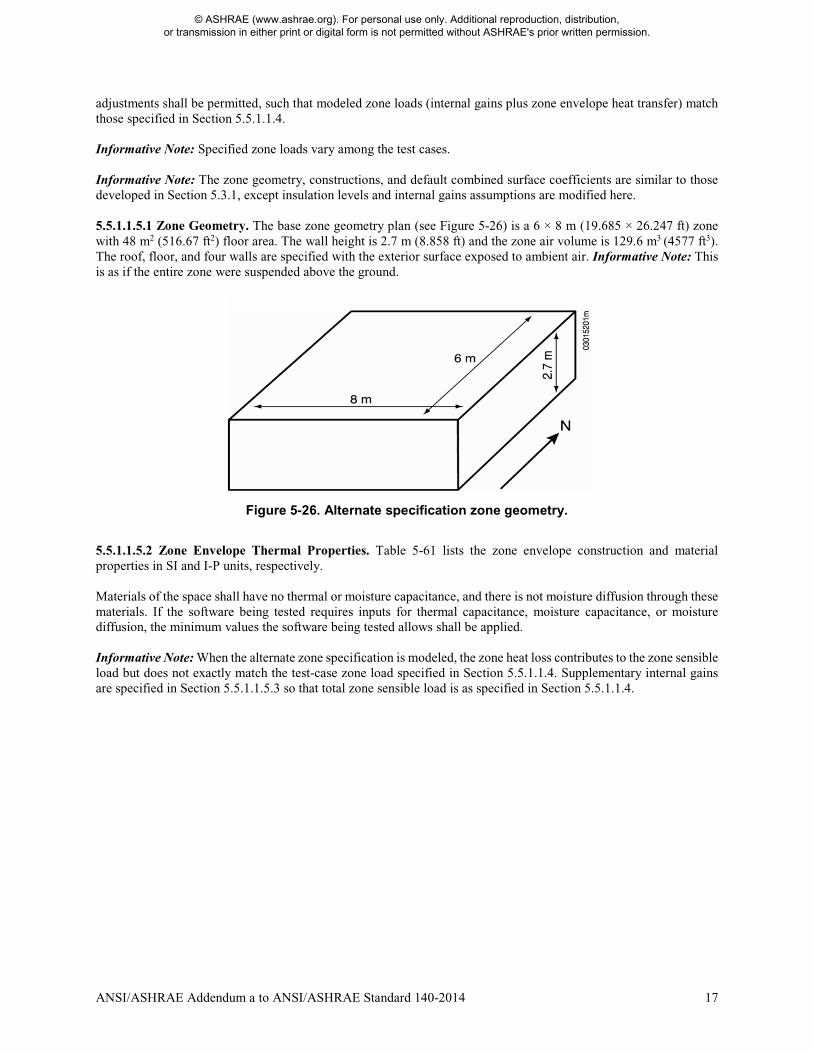
adjustments shall be permitted, such that modeled zone loads (internal gains plus zone envelope heat transfer) match those specified in Section 5.5.1.1.4. Informative Note: Specified zone loads vary among the test cases. Informative Note: The zone geometry, constructions, and default combined surface coefficients are similar to those developed in Section 5.3.1, except insulation levels and internal gains assumptions are modified here. 5.5.1.1.5.1 Zone Geometry. The base zone geometry plan (see Figure 5-26) is a 6 × 8 m (19.685 × 26.247 ft) zone with 48 m2 (516.67 ft2) floor area. The wall height is 2.7 m (8.858 ft) and the zone air volume is 129.6 m3 (4577 ft3). The roof, floor, and four walls are specified with the exterior surface exposed to ambient air. Informative Note: This is as if the entire zone were suspended above the ground.
Figure 5-26. Alternate specification zone geometry.
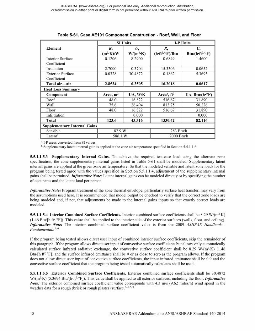
5.5.1.1.5.2 Zone Envelope Thermal Properties. Table 5-61 lists the zone envelope construction and material properties in SI and I-P units, respectively. Materials of the space shall have no thermal or moisture capacitance, and there is not moisture diffusion through these materials. If the software being tested requires inputs for thermal capacitance, moisture capacitance, or moisture diffusion, the minimum values the software being tested allows shall be applied. Informative Note: When the alternate zone specification is modeled, the zone heat loss contributes to the zone sensible load but does not exactly match the test-case zone load specified in Section 5.5.1.1.4. Supplementary internal gains are specified in Section 5.5.1.1.5.3 so that total zone sensible load is as specified in Section 5.5.1.1.4.
© ASHRAE (www.ashrae.org). For personal use only. Additional reproduction, distribution, or transmission in either print or digital form is not permitted without ASHRAE's prior written permission.
18 ANSI/ASHRAE Addendum a to ANSI/ASHRAE Standard 140-2014
Table 5-61. Case AE101 Component Construction - Roof, Wall, and Floor
Element SI Units I-P Units
R, (m2·K)/W
U, W/(m2·K)
R, (h·ft2·°F)/Btu
U, Btu/(h·ft2·°F)
Interior Surface Coefficient
0.1206 8.2900 0.6849 1.4600
Insulation 2.7000 0.3704 15.3306 0.0652 Exterior Surface Coefficient
0.0328 30.4872 0.1862 5.3693
Total air—air 2.8534 0.3505 16.2018 0.0617 Heat Loss Summary
Component Area, m2 UA, W/K Areaa, ft2 UA, Btu/(h·°F) Roof 48.0 16.822 516.67 31.890 Wall 75.6 26.494 813.75 50.226 Floor 48.0 16.822 516.67 31.890 Infiltration 0.000 0.000 Total 123.6 43.316 1330.42 82.116
Supplementary Internal Gains Sensible 82.9 W 283 Btu/h Latentb 586.1 W 2000 Btu/h
a I-P areas converted from SI values. b Supplementary latent internal gain is applied at the zone air temperature specified in Section 5.5.1.1.6.
5.5.1.1.5.3 Supplementary Internal Gains. To achieve the required test-case load using the alternate zone specification, the zone supplementary internal gains listed in Table 5-61 shall be modeled. Supplementary latent internal gains are applied at the given zone air temperature. So that the modeled sensible and latent zone loads for the program being tested agree with the values specified in Section 5.5.1.1.4, adjustment of the supplementary internal gains shall be permitted. Informative Note: Latent internal gains can be modeled directly or by specifying the number of occupants and the latent load per person. Informative Note: Program treatment of the zone thermal envelope, particularly surface heat transfer, may vary from the assumptions used here. It is recommended that model output be checked to verify that the correct zone loads are being modeled and, if not, that adjustments be made to the internal gains inputs so that exactly correct loads are modeled. 5.5.1.1.5.4 Interior Combined Surface Coefficients. Interior combined surface coefficients shall be 8.29 W/(m2⋅K) (1.46 Btu/[h⋅ft2⋅°F]). This value shall be applied to the interior side of the exterior surfaces (walls, floor, and ceiling). Informative Note: The interior combined surface coefficient value is from the 2009 ASHRAE Handbook—Fundamentals A-6.
If the program being tested allows direct user input of combined interior surface coefficients, skip the remainder of this paragraph. If the program allows direct user input of convective surface coefficients but allows only automatically calculated surface infrared radiative exchange, the convective surface coefficient shall be 8.29 W/(m2⋅K) (1.46 Btu/[h⋅ft2⋅°F]) and the surface infrared emittance shall be 0 or as close to zero as the program allows. If the program does not allow direct user input of convective surface coefficients, the input infrared emittance shall be 0.9 and the convective surface coefficient that the program being tested automatically calculates shall be used. 5.5.1.1.5.5 Exterior Combined Surface Coefficients. Exterior combined surface coefficients shall be 30.4872 W/(m2⋅K) (5.3694 Btu/[h⋅ft2⋅°F]). This value shall be applied to all exterior surfaces, including the floor. Informative Note: The exterior combined surface coefficient value corresponds with 4.3 m/s (9.62 miles/h) wind speed in the weather data for a rough (brick or rough plaster) surface.A-8,A-9
© ASHRAE (www.ashrae.org). For personal use only. Additional reproduction, distribution, or transmission in either print or digital form is not permitted without ASHRAE's prior written permission.
ANSI/ASHRAE Addendum a to ANSI/ASHRAE Standard 140-2014 19
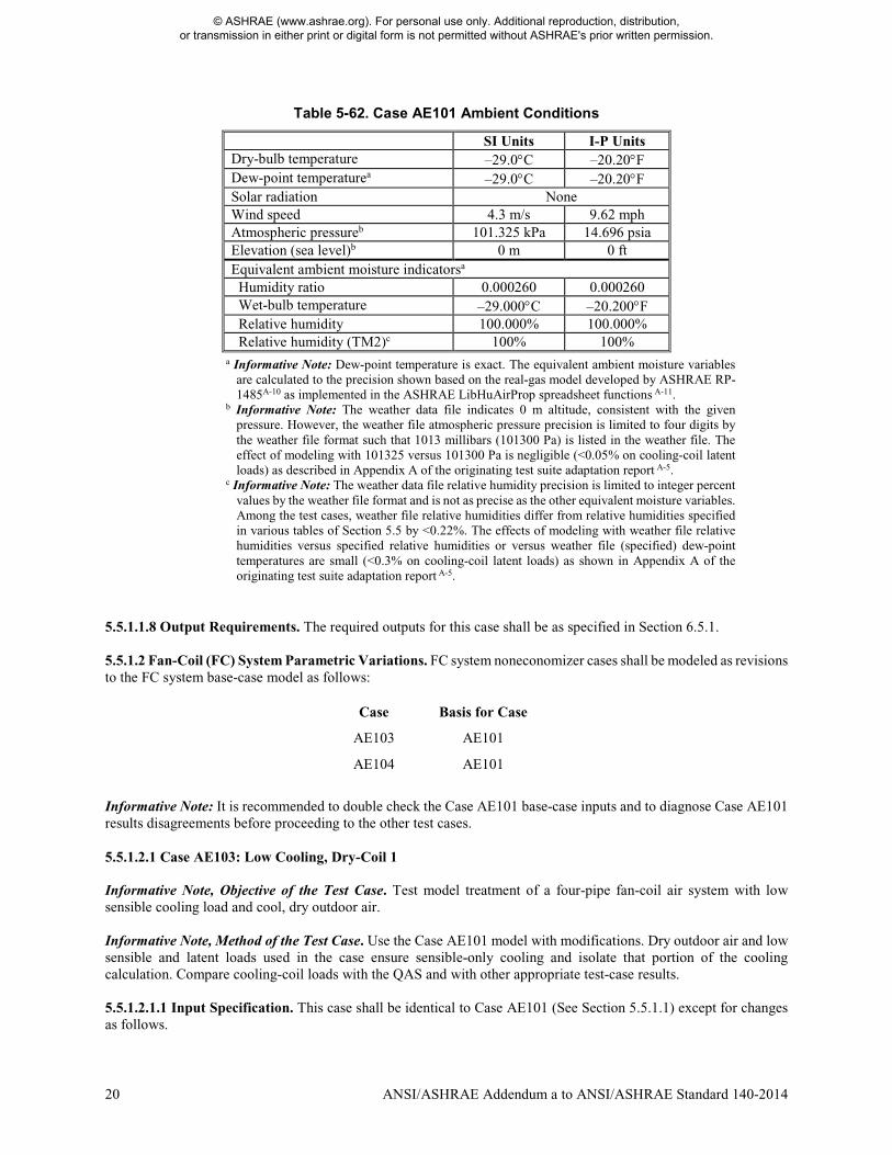
If the program being tested allows direct user input of combined exterior surface coefficients, skip the remainder of this paragraph. If the program allows direct user input of convective surface coefficients but allows only automatically calculated surface infrared radiative exchange, the convective surface coefficient shall be 30.4872 W/(m2⋅K) (5.3694 Btu/[h⋅ft2⋅°F]) and the surface infrared emittance shall be 0 or as close to zero as the program allows. If the program does not allow direct user input of convective surface coefficients, the input infrared emittance shall be 0.9 and the convective surface coefficient that the program automatically calculates shall be used. 5.5.1.1.6 Zone Temperature and Thermostat Setpoint. The zone air temperature shall be as follows: Zone dry-bulb temperature = 21.111°C (70.0°F) 5.5.1.1.6.1 There shall be no zone humidity control. Informative Note: This means that the zone humidity floats in accordance with moisture in the outdoor air introduced by the system, zone latent load, and moisture removal by the mechanical system. 5.5.1.1.6.2 The thermostat shall sense only the zone air temperature; the thermostat itself shall not sense any radiant heat transfer exchange with the interior surfaces. 5.5.1.1.6.3 The controls for this system are ideal in that the equipment shall maintain the setpoint exactly when it is operating. There are no minimum ON or OFF time-duration requirements for the unit and no hysteresis control band (e.g., there is no ON at setpoint + x°C or OFF at setpoint – y°C). If the software being tested requires input for these, the minimum values the software being tested allows shall be used. To eliminate temperature offset so that the modeled zone air temperature agrees exactly with the test-case specification, adjustment of the modeled zone thermostat setpoint shall be permitted and such adjustment shall be allowed to vary among test cases. 5.5.1.1.6.4 The thermostat is nonproportional. Informative Note: A nonproportional thermostat operates such that when the conditioned zone air temperature exceeds the thermostat cooling setpoint, the heat extraction rate is assumed to equal the maximum capacity of the cooling equipment corresponding to environmental conditions at the time of operation. A proportional thermostat throttles the heat difference between the zone setpoint temperature and the actual zone temperature. A proportional thermostat model can be made to approximate a nonproportional thermostat model by setting a very small throttling range (the minimum allowed by the software being tested). 5.5.1.1.7 Ambient Conditions. The ambient conditions specified in Table 5-62 shall be used. If the tested program does not allow constant steady-state ambient conditions to be input directly, the TMY2-format weather data provided with the following file shall be applied:
AE101.TM2 These data are provided with the accompanying electronic media and are described in Normative Annex A1, Section A1.3. Informative Note: Other cases call for different weather files as needed. Informative Note: Some programs allow constant steady-state ambient conditions to be input directly for design-day calculations.
© ASHRAE (www.ashrae.org). For personal use only. Additional reproduction, distribution, or transmission in either print or digital form is not permitted without ASHRAE's prior written permission.
20 ANSI/ASHRAE Addendum a to ANSI/ASHRAE Standard 140-2014
Table 5-62. Case AE101 Ambient Conditions
SI Units I-P Units Dry-bulb temperature –29.0°C –20.20°F Dew-point temperaturea –29.0°C –20.20°F Solar radiation None Wind speed 4.3 m/s 9.62 mph Atmospheric pressureb 101.325 kPa 14.696 psia Elevation (sea level)b 0 m 0 ft Equivalent ambient moisture indicatorsa Humidity ratio 0.000260 0.000260 Wet-bulb temperature –29.000°C –20.200°F Relative humidity 100.000% 100.000% Relative humidity (TM2)c 100% 100%
a Informative Note: Dew-point temperature is exact. The equivalent ambient moisture variables are calculated to the precision shown based on the real-gas model developed by ASHRAE RP-1485A-10 as implemented in the ASHRAE LibHuAirProp spreadsheet functions A-11.
b Informative Note: The weather data file indicates 0 m altitude, consistent with the given pressure. However, the weather file atmospheric pressure precision is limited to four digits by the weather file format such that 1013 millibars (101300 Pa) is listed in the weather file. The effect of modeling with 101325 versus 101300 Pa is negligible (<0.05% on cooling-coil latent loads) as described in Appendix A of the originating test suite adaptation report A-5.
c Informative Note: The weather data file relative humidity precision is limited to integer percent values by the weather file format and is not as precise as the other equivalent moisture variables. Among the test cases, weather file relative humidities differ from relative humidities specified in various tables of Section 5.5 by <0.22%. The effects of modeling with weather file relative humidities versus specified relative humidities or versus weather file (specified) dew-point temperatures are small (<0.3% on cooling-coil latent loads) as shown in Appendix A of the originating test suite adaptation report A-5.
5.5.1.1.8 Output Requirements. The required outputs for this case shall be as specified in Section 6.5.1. 5.5.1.2 Fan-Coil (FC) System Parametric Variations. FC system noneconomizer cases shall be modeled as revisions to the FC system base-case model as follows:
Case Basis for Case
AE103 AE101
AE104 AE101
Informative Note: It is recommended to double check the Case AE101 base-case inputs and to diagnose Case AE101 results disagreements before proceeding to the other test cases. 5.5.1.2.1 Case AE103: Low Cooling, Dry-Coil 1 Informative Note, Objective of the Test Case. Test model treatment of a four-pipe fan-coil air system with low sensible cooling load and cool, dry outdoor air. Informative Note, Method of the Test Case. Use the Case AE101 model with modifications. Dry outdoor air and low sensible and latent loads used in the case ensure sensible-only cooling and isolate that portion of the cooling calculation. Compare cooling-coil loads with the QAS and with other appropriate test-case results. 5.5.1.2.1.1 Input Specification. This case shall be identical to Case AE101 (See Section 5.5.1.1) except for changes as follows.
© ASHRAE (www.ashrae.org). For personal use only. Additional reproduction, distribution, or transmission in either print or digital form is not permitted without ASHRAE's prior written permission.
ANSI/ASHRAE Addendum a to ANSI/ASHRAE Standard 140-2014 21
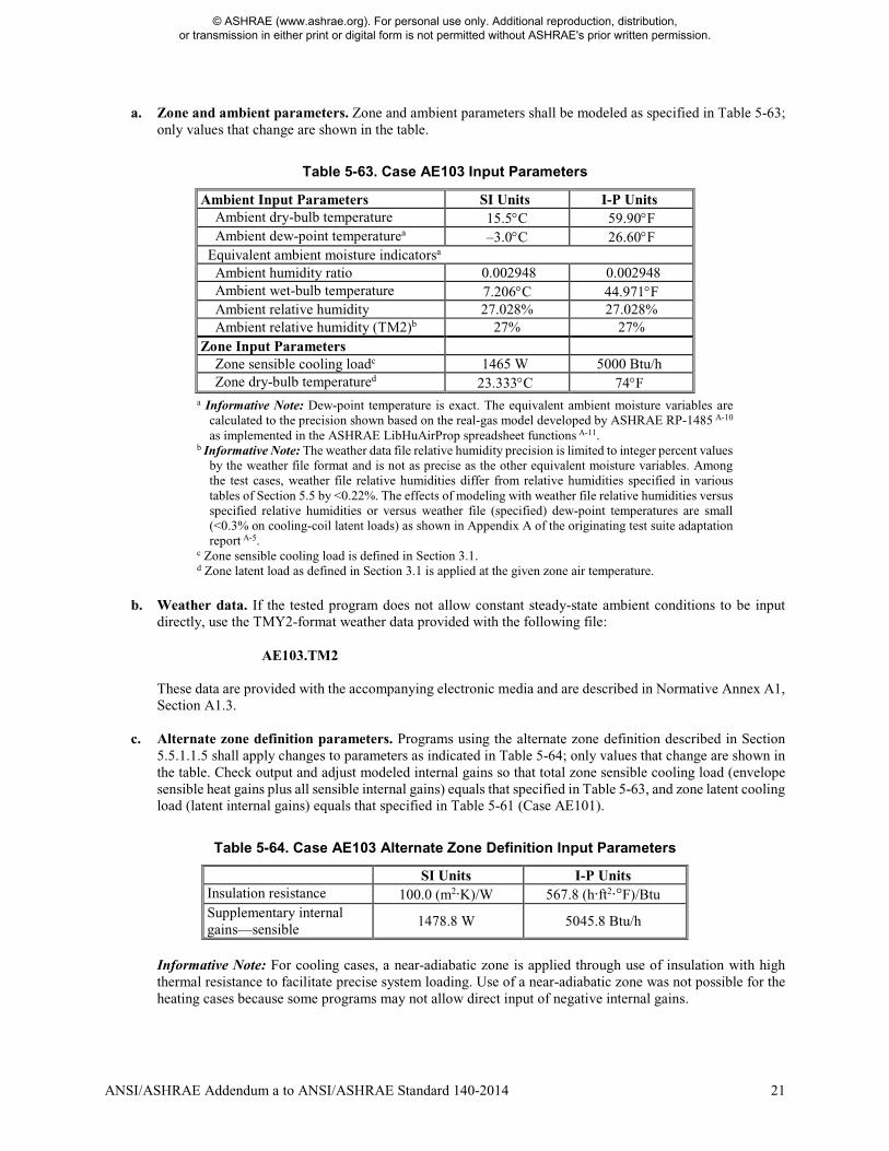
a. Zone and ambient parameters. Zone and ambient parameters shall be modeled as specified in Table 5-63; only values that change are shown in the table.
Table 5-63. Case AE103 Input Parameters
Ambient Input Parameters SI Units I-P Units Ambient dry-bulb temperature 15.5°C 59.90°F Ambient dew-point temperaturea –3.0°C 26.60°F Equivalent ambient moisture indicatorsa Ambient humidity ratio 0.002948 0.002948 Ambient wet-bulb temperature 7.206°C 44.971°F Ambient relative humidity 27.028% 27.028% Ambient relative humidity (TM2)b 27% 27% Zone Input Parameters Zone sensible cooling loadc 1465 W 5000 Btu/h Zone dry-bulb temperatured 23.333°C 74°F
a Informative Note: Dew-point temperature is exact. The equivalent ambient moisture variables are calculated to the precision shown based on the real-gas model developed by ASHRAE RP-1485 A-10 as implemented in the ASHRAE LibHuAirProp spreadsheet functions A-11.
b Informative Note: The weather data file relative humidity precision is limited to integer percent values by the weather file format and is not as precise as the other equivalent moisture variables. Among the test cases, weather file relative humidities differ from relative humidities specified in various tables of Section 5.5 by <0.22%. The effects of modeling with weather file relative humidities versus specified relative humidities or versus weather file (specified) dew-point temperatures are small (<0.3% on cooling-coil latent loads) as shown in Appendix A of the originating test suite adaptation report A-5.
c Zone sensible cooling load is defined in Section 3.1. d Zone latent load as defined in Section 3.1 is applied at the given zone air temperature.
b. Weather data. If the tested program does not allow constant steady-state ambient conditions to be input
directly, use the TMY2-format weather data provided with the following file:
AE103.TM2
These data are provided with the accompanying electronic media and are described in Normative Annex A1, Section A1.3.
c. Alternate zone definition parameters. Programs using the alternate zone definition described in Section
5.5.1.1.5 shall apply changes to parameters as indicated in Table 5-64; only values that change are shown in the table. Check output and adjust modeled internal gains so that total zone sensible cooling load (envelope sensible heat gains plus all sensible internal gains) equals that specified in Table 5-63, and zone latent cooling load (latent internal gains) equals that specified in Table 5-61 (Case AE101).
Table 5-64. Case AE103 Alternate Zone Definition Input Parameters
SI Units I-P Units Insulation resistance 100.0 (m2·K)/W 567.8 (h·ft2·°F)/Btu Supplementary internal gains—sensible
1478.8 W 5045.8 Btu/h
Informative Note: For cooling cases, a near-adiabatic zone is applied through use of insulation with high thermal resistance to facilitate precise system loading. Use of a near-adiabatic zone was not possible for the heating cases because some programs may not allow direct input of negative internal gains.
© ASHRAE (www.ashrae.org). For personal use only. Additional reproduction, distribution, or transmission in either print or digital form is not permitted without ASHRAE's prior written permission.
22 ANSI/ASHRAE Addendum a to ANSI/ASHRAE Standard 140-2014
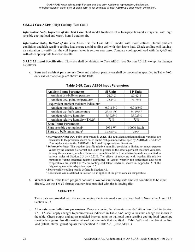
5.5.1.2.2 Case AE104: High Cooling, Wet-Coil 1 Informative Note, Objective of the Test Case. Test model treatment of a four-pipe fan-coil air system with high sensible cooling load and warm, humid outdoor air. Informative Note, Method of the Test Case. Use the Case AE101 model with modifications. Humid ambient conditions and high sensible cooling load ensure a cold cooling coil with high latent load. Check cooling-coil leaving-air saturation to verify that the coil bypass factor is zero or near zero. Compare cooling-coil load with the QAS and with other appropriate test-case results. 5.5.1.2.2.1 Input Specification. This case shall be identical to Case AE101 (See Section 5.5.1.1) except for changes as follows.
a. Zone and ambient parameters. Zone and ambient parameters shall be modeled as specified in Table 5-65; only values that change are shown in the table.
Table 5-65. Case AE104 Input Parameters
Ambient Input Parameters SI Units I-P Units Ambient dry-bulb temperature 26.9°C 80.42°F Ambient dew-point temperaturea 22.1°C 71.78°F Equivalent ambient moisture indicatorsa Ambient humidity ratio 0.016849 0.016849 Ambient wet-bulb temperature 23.441°C 74.194°F Ambient relative humidity 75.023% 75.023% Ambient relative humidity (TM2)b 75% 75% Zone Input Parameters Zone sensible cooling loadc 2931 W 10000 Btu/h Zone dry-bulb temperatured 23.889°C 75°F
a Informative Note: Dew-point temperature is exact. The equivalent ambient moisture variables are calculated to the precision shown based on the real-gas model developed by ASHRAE RP-1485A-
10 as implemented in the ASHRAE LibHuAirProp spreadsheet functions A-11. b Informative Note: The weather data file relative humidity precision is limited to integer percent
values by the weather file format and is not as precise as the other equivalent moisture variables. Among the test cases, weather file relative humidities differ from relative humidities specified in various tables of Section 5.5 by <0.22%. The effects of modeling with weather file relative humidities versus specified relative humidities or versus weather file (specified) dew-point temperatures are small (<0.3% on cooling-coil latent loads) as shown in Appendix A of the originating test suite adaptation report A-5.
c Zone sensible cooling load is defined in Section 3.1. d Zone latent load as defined in Section 3.1 is applied at the given zone air temperature.
b. Weather data. If the tested program does not allow constant steady-state ambient conditions to be input
directly, use the TMY2-format weather data provided with the following file: AE104.TM2
These data are provided with the accompanying electronic media and are described in Normative Annex A1, Section A1.3.
c. Alternate zone definition parameters. Programs using the alternate zone definition described in Section 5.5.1.1.5 shall apply changes to parameters as indicated in Table 5-66; only values that change are shown in the table. Check output and adjust modeled internal gains so that total zone sensible cooling load (envelope sensible heat gains plus all sensible internal gains) equals that specified in Table 5-65, and zone latent cooling load (latent internal gains) equals that specified in Table 5-61 (Case AE101).
© ASHRAE (www.ashrae.org). For personal use only. Additional reproduction, distribution, or transmission in either print or digital form is not permitted without ASHRAE's prior written permission.
ANSI/ASHRAE Addendum a to ANSI/ASHRAE Standard 140-2014 23
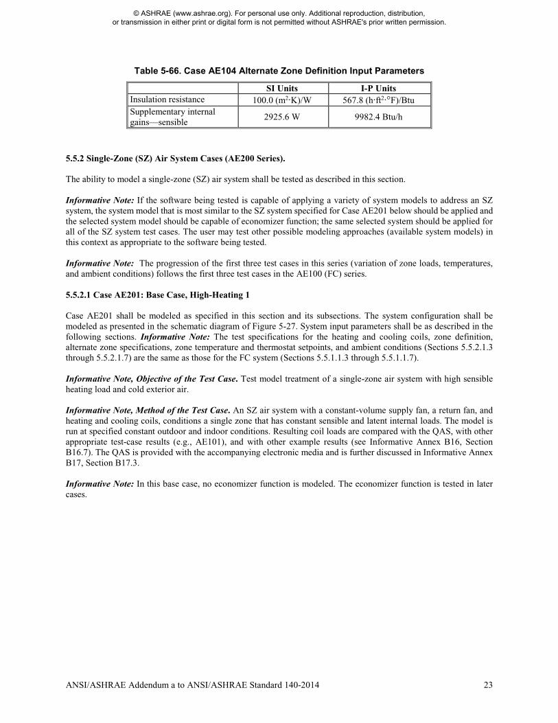
Table 5-66. Case AE104 Alternate Zone Definition Input Parameters
SI Units I-P Units Insulation resistance 100.0 (m2·K)/W 567.8 (h·ft2·°F)/Btu Supplementary internal gains—sensible
2925.6 W 9982.4 Btu/h
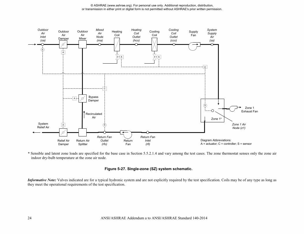
5.5.2 Single-Zone (SZ) Air System Cases (AE200 Series). The ability to model a single-zone (SZ) air system shall be tested as described in this section. Informative Note: If the software being tested is capable of applying a variety of system models to address an SZ system, the system model that is most similar to the SZ system specified for Case AE201 below should be applied and the selected system model should be capable of economizer function; the same selected system should be applied for all of the SZ system test cases. The user may test other possible modeling approaches (available system models) in this context as appropriate to the software being tested. Informative Note: The progression of the first three test cases in this series (variation of zone loads, temperatures, and ambient conditions) follows the first three test cases in the AE100 (FC) series. 5.5.2.1 Case AE201: Base Case, High-Heating 1 Case AE201 shall be modeled as specified in this section and its subsections. The system configuration shall be modeled as presented in the schematic diagram of Figure 5-27. System input parameters shall be as described in the following sections. Informative Note: The test specifications for the heating and cooling coils, zone definition, alternate zone specifications, zone temperature and thermostat setpoints, and ambient conditions (Sections 5.5.2.1.3 through 5.5.2.1.7) are the same as those for the FC system (Sections 5.5.1.1.3 through 5.5.1.1.7). Informative Note, Objective of the Test Case. Test model treatment of a single-zone air system with high sensible heating load and cold exterior air. Informative Note, Method of the Test Case. An SZ air system with a constant-volume supply fan, a return fan, and heating and cooling coils, conditions a single zone that has constant sensible and latent internal loads. The model is run at specified constant outdoor and indoor conditions. Resulting coil loads are compared with the QAS, with other appropriate test-case results (e.g., AE101), and with other example results (see Informative Annex B16, Section B16.7). The QAS is provided with the accompanying electronic media and is further discussed in Informative Annex B17, Section B17.3. Informative Note: In this base case, no economizer function is modeled. The economizer function is tested in later cases.
© ASHRAE (www.ashrae.org). For personal use only. Additional reproduction, distribution, or transmission in either print or digital form is not permitted without ASHRAE's prior written permission.
24 ANSI/ASHRAE Addendum a to ANSI/ASHRAE Standard 140-2014
* Sensible and latent zone loads are specified for the base case in Section 5.5.2.1.4 and vary among the test cases. The zone thermostat senses only the zone air
indoor dry-bulb temperature at the zone air node.
Figure 5-27. Single-zone (SZ) system schematic.
Informative Note: Valves indicated are for a typical hydronic system and are not explicitly required by the test specification. Coils may be of any type as long as they meet the operational requirements of the test specification.
Bypass Damper
Relief Air Damper
HeatingCoil
Cooling Coil
Supply Fan
Zone 1*
Return Fan
c
A
A
A
A A
C
S
S
Outdoor Air
Inlet(oa)
Mixed Air
Node(ma)
HeatingCoil
Outlet(hco)
Cooling Coil
Outlet(cco)
SystemSupply
Air(sa)
Zone 1 Exhaust Fan
Recirculated Air
Zone 1 Air Node (z1)
Return Fan Inlet(rfi)
Return Fan Outlet(rfo)
SystemRelief Air
Outdoor Air
Damper
S
Return Air Splitter
Outdoor Air
Mixer
Diagram Abbreviations: A = actuator; C = controller; S = sensor
© ASHRAE (www.ashrae.org). For personal use only. Additional reproduction, distribution, or transmission in either print or digital form is not permitted without ASHRAE's prior written permission.
ANSI/ASHRAE Addendum a to ANSI/ASHRAE Standard 140-2014 25
5.5.2.1.1 Fan Operation. The system shall have a supply fan, return fan, and zone exhaust fan. 5.5.2.1.1.1 Supply Fan. The supply fan characteristics shall be as follows:
a. The fan is located downstream of the heating and cooling coils as specified in Figure 5-27. b. The supply fan total pressure rise = 2.0 in. of water (498 Pa). c. The fan provides a constant volume of supply air, measured at the fan inlet, as specified in Section 5.5.2.1.2. d. The fan operates continuously. e. Fan energy is transferred to the air that is being moved. f. Fan motor and transmission drive energy loss is not transferred to the moving air. g. (Fan heat to airstream) = Ho × [1/(Fan mechanical efficiency) – 1], where
• Ho is the fan output power required to meet the specified airflow requirements; see Ho under fan mechanical efficiency in Section 3.1.
• fan mechanical efficiency = 0.7, constant value; fan mechanical efficiency is defined in Section 3.1. h. (Fan motor input power) = Ho/[(Fan mechanical efficiency) × (Transmission drive efficiency) × (Motor
efficiency)], where • 0 ≤ (Transmission drive efficiency) ≤ 1; transmission drive efficiency is defined in Section 3.1. • 0 ≤ (Motor efficiency) ≤ 1; motor efficiency is defined in Section 3.1.
If the program being tested is not able to model the transmission drive and motor losses as occurring outside the airstream, the fan, transmission drive, and motor efficiency losses shall be specified to have a combined efficiency of 0.7 and to occur in the airstream. Informative Note: The airstream heat gain (fan heat) affects the test-case outputs, while the motor and transmission drive input energy do not; therefore, the transmission and motor efficiency may be any value as long as their heat is not imparted to the airstream and the fan mechanical efficiency = 0.7.
Informative Note: The supply fan characteristics are the same as for the FC system (see Section 5.5.1.1.1). 5.5.2.1.1.2 Return Fan. The return fan characteristics shall be as follows:
a. The fan is located downstream from the zone and before the return-air splitter as specified in Figure 5-27. b. The return fan total pressure rise = 1.0 in. of water (249 Pa) at 400 cfm (188.78 L/s). c. The return fan total pressure rise varies as
Pressure rise [in. of water] = (1.0 in. of water) × [(Actual return fan cfm)/(400 cfm)]2. d. The fan returns an air volume as specified in Section 5.5.2.1.2. e. The fan operates continuously. f. Fan energy is transferred to the air that is being moved. g. Fan motor and transmission drive energy loss is not transferred to the moving air. h. (Fan heat to airstream) = Ho × [1/(Fan mechanical efficiency) – 1], where
• Ho is the fan output power required to meet the specified airflow requirements; see Ho under fan mechanical efficiency in Section 3.1
• fan mechanical efficiency = 0.7, constant value; fan mechanical efficiency is defined in Section 3.1 i. (Fan motor input power) = Ho/[(Fan mechanical efficiency) × (Transmission drive efficiency) × (Motor
efficiency)], where • 0 ≤ (Transmission drive efficiency) ≤ 1; transmission drive efficiency is defined in Section 3.1 • 0 ≤ (Motor efficiency) ≤ 1; motor efficiency is defined in Section 3.1.
If the program being tested is not able to model the transmission drive and motor losses as occurring outside the airstream, the fan, transmission drive, and motor efficiency losses shall be specified to have a combined efficiency of 0.7 and to occur in the airstream.
© ASHRAE (www.ashrae.org). For personal use only. Additional reproduction, distribution, or transmission in either print or digital form is not permitted without ASHRAE's prior written permission.

26 ANSI/ASHRAE Addendum a to ANSI/ASHRAE Standard 140-2014
Informative Note: The airstream heat gain (fan heat) affects the test-case outputs, while the motor and transmission drive input energy do not; therefore, the transmission and motor efficiency may be any value as long as their heat is not imparted to the airstream and the fan mechanical efficiency = 0.7.
5.5.2.1.1.3 Exhaust Fan. The zone exhaust fan shall maintain airflow as specified in Section 5.5.2.1.2. Informative Note: Exhaust fan details are not defined explicitly, as the exhaust fan’s characteristics have no impact on the results of the test case. 5.5.2.1.1.4 Programs with Predetermined Fan Modeling Assumptions. Programs with predetermined fan modeling assumptions shall be permitted to apply those assumptions. Informative Note: For example, a program may model the return air fan pressure increase using its default assumptions if they are not normally adjustable by a typical program user. 5.5.2.1.2 Airflows. System and zone airflows shall be as shown in Table 5-67 and the following subsections.
Table 5-67. Case AE201 System and Zone Airflows
Input Parameter SI Units I-P Units System supply airflow rate 283.17 L/s a 600 cfm a Design system return airflow rate 188.78 L/s b 400 cfm b Zone exhaust airflow rate 94.39 L/s c 200 cfm c
a Volumetric airflow rate at the supply fan inlet conditions; see Section 5.5.2.1.2.1. b This is the volumetric airflow rate on which the return fan pressure rise (1 in. of water at 400 cfm) is based; see Section 5.5.2.1.1.2(b) and (c). The actual return airflow rate shall be permitted to vary from the design airflow rate and is defined in Section 5.5.2.1.2.3.
c Volumetric airflow rate at the exhaust fan inlet conditions; see Section 5.5.2.1.2.2. 5.5.2.1.2.1 System Supply Air. The system supply airflow rate shall be volumetrically constant and is measured at the supply fan inlet. Informative Note: As the temperature and humidity ratio of the air entering the supply fan change, the specific volume of that air changes. This means that the mass flow rate of supply air, while constant for a given steady-state test case, varies among the test cases based on fan inlet conditions. The mass flow rate of the zone supply air is equal to that of the system supply air. Informative Note: The QAS calculates the system mass flow rate from the volumetric flow using the local specific volume of air entering the supply fan. Results differences versus the QAS can be caused by differences in the method and assumptions a tested program uses to convert volumetric flow to mass flow. Example results for the QAS, including detailed outputs (e.g., mass flow rate, specific volume, enthalpy) at specific system locations, are provided in Informative Annex B16, Section B16.7; assumptions of the QAS for converting volumetric flows to mass flows are provided in Part II of the originating test suite adaptation report A-5. 5.5.2.1.2.2 Zone Exhaust Air. The zone exhaust airflow rate shall be volumetrically constant and is measured at the exhaust fan inlet conditions. Informative Note: The QAS calculates the exhaust air mass flow rate from the volumetric flow using the local specific volume of the air entering the exhaust fan (i.e., the zone air properties); see Part II of the originating test suite adaptation report A-5. Informative Note: As the temperature and humidity ratio of the air entering the exhaust fan change, the specific volume of that air changes. This means that the mass flow rate of exhaust air, while constant for a given steady-state test case, varies among the test cases based on zone conditions.
© ASHRAE (www.ashrae.org). For personal use only. Additional reproduction, distribution, or transmission in either print or digital form is not permitted without ASHRAE's prior written permission.
ANSI/ASHRAE Addendum a to ANSI/ASHRAE Standard 140-2014 27
5.5.2.1.2.3 Return Airflow. The return airflow rate shall be the air volume, as measured at the return fan inlet, necessary to move an air mass equal to the zone supply mass flow minus the zone exhaust mass flow. Informative Note: The return fan volumetric flow rate in the QAS is calculated from the return air mass flow using the specific volume of air entering the return fan; see Part II of the originating test suite adaptation report A-5. The return fan volumetric flow varies with the return air mass flow and the specific volume of the air entering the return fan. 5.5.2.1.2.4 Outdoor Air. The flow of outdoor air shall be introduced at a mass flow rate equal to the zone exhaust air mass flow rate. For programs that do not precisely apply the specified mass flow balance, introduction of outdoor air to replace the specified exhaust airflow (see Table 5-67), applying the tested program’s specific assumptions regarding this calculation, shall be permitted. Informative Note: Greater amounts of outdoor air may be required in other test cases applying economizer control logic. 5.5.2.1.2.5 Frictionless Ducts, Coils, and Dampers. Airflow through ducts, coils, and dampers shall be frictionless, such that there shall be no pressure drops through these components. If the software being tested does not allow frictionless components, the model shall apply the least amount of friction in these components that the software being tested allows. Informative Note: Modeling of fan heat is as described previously in Section 5.5.2.1.1. 5.5.2.1.2.6 HVAC System Component Air Leakage and Heat Loss. HVAC system components, including ducts, mixing boxes, dampers, fans, and coils, shall have no air leakage and shall have no heat exchange (gains or losses) with their external surroundings. If the software being tested does not allow zero system air leakage or zero external heat gains or losses for HVAC system components, the model shall apply the least amount of air leakage and external heat exchange that the software being tested allows. Informative Note: Modeling of exhaust and outdoor airflows is as described previously in Sections 5.5.2.1.2.2 and 5.5.2.1.2.4. Modeling of heating and cooling coils is as described in Section 5.5.2.1.3. 5.5.2.1.3 Operation of Heating and Cooling Coils. The heating and cooling coils shall be modeled as specified for the FC system test base case in Section 5.5.1.1.3. 5.5.2.1.4 Zone Definition. For programs that are not able to specify zone loads directly and are not able to define an adiabatic zone with negative internal gains, skip the remainder of this section and model the zone by applying the alternative nonadiabatic zone specified in Section 5.5.2.1.5. A single zone shall be modeled as specified for the FC system test base case in Section 5.5.1.1.4. 5.5.2.1.5 Alternate Zone Specification. If the program being tested was able to model this test case as specified in Section 5.5.2.1.4, skip this section and proceed to Section 5.5.2.1.6. For programs that require nonadiabatic zones or are not able to model negative internal gains, the alternate zone specification for the FC system test base case in Section 5.5.1.1.5 shall be applied. 5.5.2.1.6 Zone Temperature and Thermostat Setpoint. These shall be the same as for the FC system test base case as specified in Section 5.5.1.1.6. 5.5.2.1.7 Ambient Conditions. The ambient conditions shall be the same as for the FC system test base case as specified in Section 5.5.1.1.7. 5.5.2.1.8 Output Requirements. The required outputs for this case shall be as specified in Section 6.5.2. 5.5.2.2 Single-Zone (SZ) System Parametric Variations, No Economizer. SZ system noneconomizer cases shall be modeled as revisions to the SZ system base-case model as follows.
© ASHRAE (www.ashrae.org). For personal use only. Additional reproduction, distribution, or transmission in either print or digital form is not permitted without ASHRAE's prior written permission.
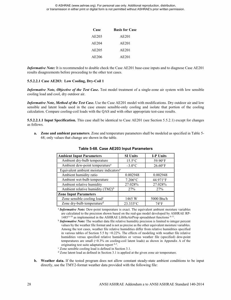
28 ANSI/ASHRAE Addendum a to ANSI/ASHRAE Standard 140-2014
Case Basis for Case
AE203 AE201
AE204 AE201
AE205 AE201
AE206 AE201
Informative Note: It is recommended to double check the Case AE201 base-case inputs and to diagnose Case AE201 results disagreements before proceeding to the other test cases. 5.5.2.2.1 Case AE203: Low Cooling, Dry-Coil 1 Informative Note, Objective of the Test Case. Test model treatment of a single-zone air system with low sensible cooling load and cool, dry outdoor air. Informative Note, Method of the Test Case. Use the Case AE201 model with modifications. Dry outdoor air and low sensible and latent loads used in the case ensure sensible-only cooling and isolate that portion of the cooling calculation. Compare cooling-coil loads with the QAS and with other appropriate test-case results. 5.5.2.2.1.1 Input Specification. This case shall be identical to Case AE201 (see Section 5.5.2.1) except for changes as follows.
a. Zone and ambient parameters. Zone and temperature parameters shall be modeled as specified in Table 5-
68; only values that change are shown in the table.
Table 5-68. Case AE203 Input Parameters
Ambient Input Parameters SI Units I-P Units Ambient dry-bulb temperature 15.5°C 59.90°F Ambient dew-point temperaturea –3.0°C 26.60°F Equivalent ambient moisture indicatorsa Ambient humidity ratio 0.002948 0.002948 Ambient wet-bulb temperature 7.206°C 44.971°F Ambient relative humidity 27.028% 27.028% Ambient relative humidity (TM2)b 27% 27% Zone Input Parameters Zone sensible cooling loadc 1465 W 5000 Btu/h Zone dry-bulb temperatured 23.333°C 74°F a Informative Note: Dew-point temperature is exact. The equivalent ambient moisture variables
are calculated to the precision shown based on the real-gas model developed by ASHRAE RP-1485A-10 as implemented in the ASHRAE LibHuAirProp spreadsheet functions A-11.
b Informative Note: The weather data file relative humidity precision is limited to integer percent values by the weather file format and is not as precise as the other equivalent moisture variables. Among the test cases, weather file relative humidities differ from relative humidities specified in various tables of Section 5.5 by <0.22%. The effects of modeling with weather file relative humidities versus specified relative humidities or versus weather file (specified) dew-point temperatures are small (<0.3% on cooling-coil latent loads) as shown in Appendix A of the originating test suite adaptation report A-5.
c Zone sensible cooling load is defined in Section 3.1. d Zone latent load as defined in Section 3.1 is applied at the given zone air temperature.
b. Weather data. If the tested program does not allow constant steady-state ambient conditions to be input directly, use the TMY2-format weather data provided with the following file:
© ASHRAE (www.ashrae.org). For personal use only. Additional reproduction, distribution, or transmission in either print or digital form is not permitted without ASHRAE's prior written permission.
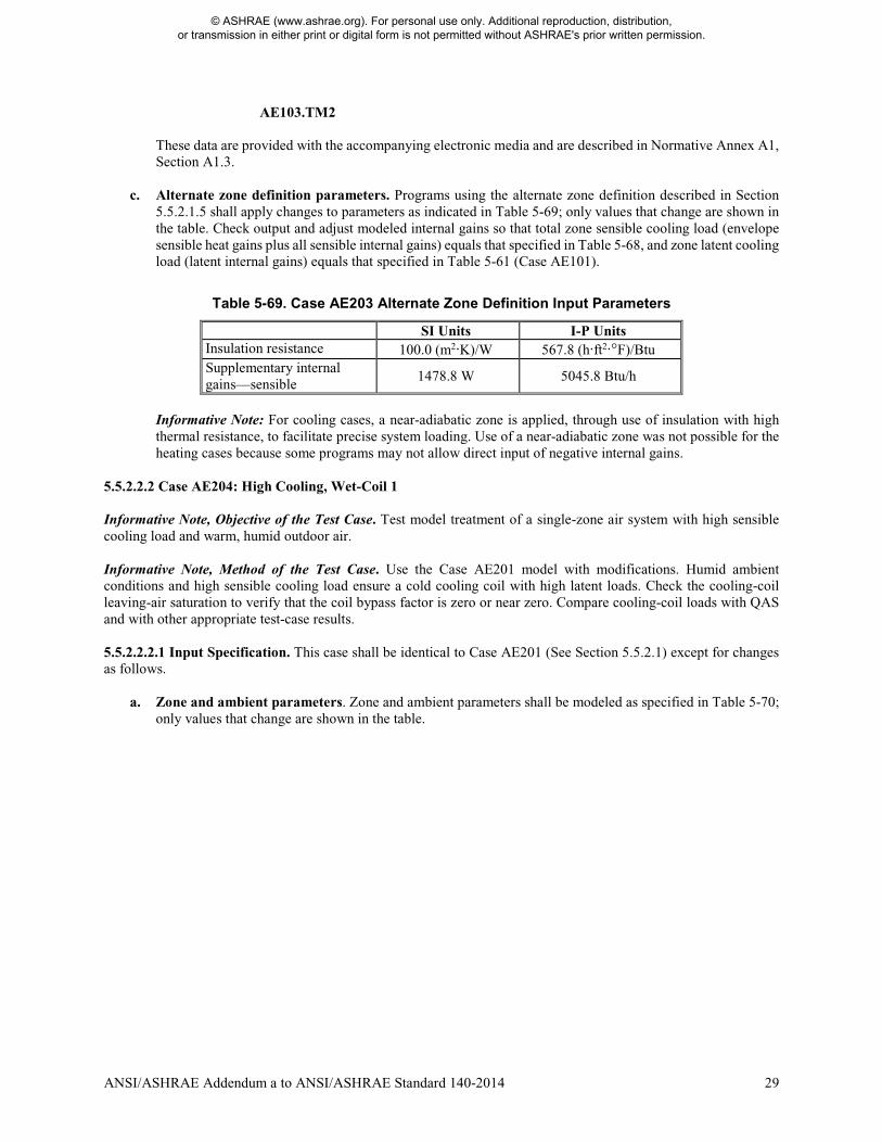
ANSI/ASHRAE Addendum a to ANSI/ASHRAE Standard 140-2014 29
AE103.TM2
These data are provided with the accompanying electronic media and are described in Normative Annex A1, Section A1.3.
c. Alternate zone definition parameters. Programs using the alternate zone definition described in Section
5.5.2.1.5 shall apply changes to parameters as indicated in Table 5-69; only values that change are shown in the table. Check output and adjust modeled internal gains so that total zone sensible cooling load (envelope sensible heat gains plus all sensible internal gains) equals that specified in Table 5-68, and zone latent cooling load (latent internal gains) equals that specified in Table 5-61 (Case AE101).
Table 5-69. Case AE203 Alternate Zone Definition Input Parameters
SI Units I-P Units Insulation resistance 100.0 (m2·K)/W 567.8 (h·ft2·°F)/Btu Supplementary internal gains—sensible
1478.8 W 5045.8 Btu/h
Informative Note: For cooling cases, a near-adiabatic zone is applied, through use of insulation with high thermal resistance, to facilitate precise system loading. Use of a near-adiabatic zone was not possible for the heating cases because some programs may not allow direct input of negative internal gains.
5.5.2.2.2 Case AE204: High Cooling, Wet-Coil 1 Informative Note, Objective of the Test Case. Test model treatment of a single-zone air system with high sensible cooling load and warm, humid outdoor air. Informative Note, Method of the Test Case. Use the Case AE201 model with modifications. Humid ambient conditions and high sensible cooling load ensure a cold cooling coil with high latent loads. Check the cooling-coil leaving-air saturation to verify that the coil bypass factor is zero or near zero. Compare cooling-coil loads with QAS and with other appropriate test-case results. 5.5.2.2.2.1 Input Specification. This case shall be identical to Case AE201 (See Section 5.5.2.1) except for changes as follows.
a. Zone and ambient parameters. Zone and ambient parameters shall be modeled as specified in Table 5-70; only values that change are shown in the table.
© ASHRAE (www.ashrae.org). For personal use only. Additional reproduction, distribution, or transmission in either print or digital form is not permitted without ASHRAE's prior written permission.

30 ANSI/ASHRAE Addendum a to ANSI/ASHRAE Standard 140-2014
Table 5-70. Case AE204 Input Parameters
Ambient Input Parameters SI Units I-P Units Ambient dry-bulb temperature 26.9°C 80.42°F Ambient dew-point temperaturea 22.1°C 71.78°F Equivalent ambient moisture indicatorsa Ambient humidity ratio 0.016849 0.016849 Ambient wet-bulb temperature 23.441°C 74.194°F Ambient relative humidity 75.023% 75.023% Ambient relative humidity (TM2)b 75% 75% Zone Input Parameters Zone sensible cooling loadc 2931 W 10000 Btu/h Zone dry-bulb temperatured 23.889°C 75°F
a Informative Note: Dew-point temperature is exact. The equivalent ambient moisture variables are calculated to the precision shown based on the real-gas model developed by ASHRAE RP-1485A-
10 as implemented in the ASHRAE LibHuAirProp spreadsheet functions A-11. b Informative Note: The weather data file relative humidity precision is limited to integer percent
values by the weather file format and is not as precise as the other equivalent moisture variables. Among the test cases, weather file relative humidities differ from relative humidities specified in various tables of Section 5.5 by <0.22%. The effects of modeling with weather file relative humidities versus specified relative humidities or versus weather file (specified) dew-point temperatures are small (<0.3% on cooling-coil latent loads) as shown in Appendix A of the originating test suite adaptation report A-5.
c Zone sensible cooling load is defined in Section 3.1. d Zone latent load as defined in Section 3.1 is applied at the given zone air temperature.
b. Weather data. If the tested program does not allow constant steady-state ambient conditions to be input
directly, use the TMY2-format weather data provided with the following file: AE104.TM2
These data are provided with the accompanying electronic media and are described in Normative Annex A1, Section A1.3.
c. Alternate zone definition parameters. Programs using the alternate zone definition described in Section 5.5.2.1.5 shall apply changes to parameters as indicated in Table 5-71; only values that change are shown in the table. Check output and adjust modeled internal gains so that total zone sensible cooling load (envelope sensible heat gains plus all sensible internal gains) equals that specified in Table 5-70, and zone latent cooling load (latent internal gains) equals that specified in Table 5-61 (Case AE101).
Table 5-71. Case AE204 Alternate Zone Definition Input Parameters
SI Units I-P Units Insulation resistance 100.0 (m2·K)/W 567.8 (h·ft2·°F)/Btu Supplementary internal gains—sensible
2925.6 W 9982.4 Btu/h
5.5.2.2.3 Case AE205: Low Cooling, Dry-Coil 1 Informative Note, Objective of the Test Case. Generate results for a single-zone air system without enthalpy economizer, applying low sensible cooling load and warm, dry outdoor air to compare with results for the same system with enthalpy economizer (Case AE245). Informative Note, Method of the Test Case. Use the Case AE201 model with modifications. Case AE205 applies ambient conditions with a low wet-bulb temperature to ensure that the economizer operates when it is specified in
© ASHRAE (www.ashrae.org). For personal use only. Additional reproduction, distribution, or transmission in either print or digital form is not permitted without ASHRAE's prior written permission.
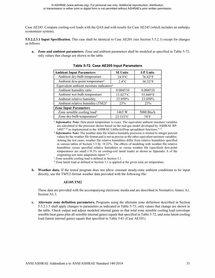
ANSI/ASHRAE Addendum a to ANSI/ASHRAE Standard 140-2014 31
Case AE245. Compare cooling-coil loads with the QAS and with results for Case AE245 (which includes an enthalpy economizer system). 5.5.2.2.3.1 Input Specification. This case shall be identical to Case AE201 (see Section 5.5.2.1) except for changes as follows.
a. Zone and ambient parameters. Zone and ambient parameters shall be modeled as specified in Table 5-72;
only values that change are shown in the table.
Table 5-72. Case AE205 Input Parameters
Ambient Input Parameters SI Units I-P Units Ambient dry-bulb temperature 24.9°C 76.82°F Ambient dew-point temperaturea 2.4°C 36.32°F Equivalent ambient moisture indicatorsa Ambient humidity ratio 0.004510 0.004510 Ambient wet-bulb temperature 13.027°C 55.449°F Ambient relative humidity 23.050% 23.050% Ambient relative humidity (TM2)b 23% 23% Zone Input Parameters Zone sensible cooling loadc 1465 W 5000 Btu/h Zone dry-bulb temperatured 23.333°C 74°F
a Informative Note: Dew-point temperature is exact. The equivalent ambient moisture variables are calculated to the precision shown based on the real-gas model developed by ASHRAE RP-1485A-10 as implemented in the ASHRAE LibHuAirProp spreadsheet functions A-11.
b Informative Note: The weather data file relative humidity precision is limited to integer percent values by the weather file format and is not as precise as the other equivalent moisture variables. Among the test cases, weather file relative humidities differ from relative humidities specified in various tables of Section 5.5 by <0.22%. The effects of modeling with weather file relative humidities versus specified relative humidities or versus weather file (specified) dew-point temperatures are small (<0.3% on cooling-coil latent loads) as shown in Appendix A of the originating test suite adaptation report A-5.
c Zone sensible cooling load is defined in Section 3.1. d Zone latent load as defined in Section 3.1 is applied at the given zone air temperature.
b. Weather data. If the tested program does not allow constant steady-state ambient conditions to be input
directly, use the TMY2-format weather data provided with the following file: AE105.TM2
These data are provided with the accompanying electronic media and are described in Normative Annex A1, Section A1.3.
c. Alternate zone definition parameters. Programs using the alternate zone definition described in Section 5.5.2.1.5 shall apply changes to parameters as indicated in Table 5-73; only values that change are shown in the table. Check output and adjust modeled internal gains so that total zone sensible cooling load (envelope sensible heat gains plus all sensible internal gains) equals that specified in Table 5-72, and zone latent cooling load (latent internal gains) equals that specified in Table 5-61 (Case AE101).
© ASHRAE (www.ashrae.org). For personal use only. Additional reproduction, distribution, or transmission in either print or digital form is not permitted without ASHRAE's prior written permission.
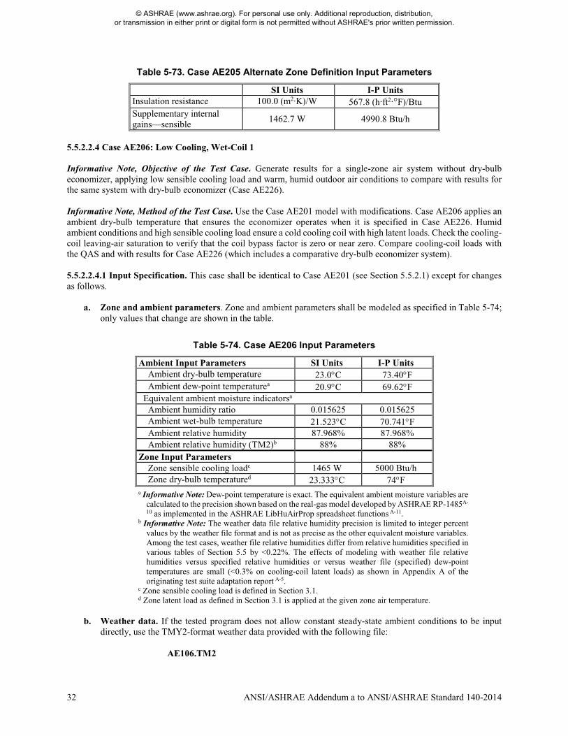
32 ANSI/ASHRAE Addendum a to ANSI/ASHRAE Standard 140-2014
Table 5-73. Case AE205 Alternate Zone Definition Input Parameters
SI Units I-P Units Insulation resistance 100.0 (m2·K)/W 567.8 (h·ft2·°F)/Btu Supplementary internal gains—sensible
1462.7 W 4990.8 Btu/h
5.5.2.2.4 Case AE206: Low Cooling, Wet-Coil 1 Informative Note, Objective of the Test Case. Generate results for a single-zone air system without dry-bulb economizer, applying low sensible cooling load and warm, humid outdoor air conditions to compare with results for the same system with dry-bulb economizer (Case AE226). Informative Note, Method of the Test Case. Use the Case AE201 model with modifications. Case AE206 applies an ambient dry-bulb temperature that ensures the economizer operates when it is specified in Case AE226. Humid ambient conditions and high sensible cooling load ensure a cold cooling coil with high latent loads. Check the cooling-coil leaving-air saturation to verify that the coil bypass factor is zero or near zero. Compare cooling-coil loads with the QAS and with results for Case AE226 (which includes a comparative dry-bulb economizer system). 5.5.2.2.4.1 Input Specification. This case shall be identical to Case AE201 (see Section 5.5.2.1) except for changes as follows.
a. Zone and ambient parameters. Zone and ambient parameters shall be modeled as specified in Table 5-74; only values that change are shown in the table.
Table 5-74. Case AE206 Input Parameters
Ambient Input Parameters SI Units I-P Units Ambient dry-bulb temperature 23.0°C 73.40°F Ambient dew-point temperaturea 20.9°C 69.62°F Equivalent ambient moisture indicatorsa Ambient humidity ratio 0.015625 0.015625 Ambient wet-bulb temperature 21.523°C 70.741°F Ambient relative humidity 87.968% 87.968% Ambient relative humidity (TM2)b 88% 88% Zone Input Parameters Zone sensible cooling loadc 1465 W 5000 Btu/h Zone dry-bulb temperatured 23.333°C 74°F a Informative Note: Dew-point temperature is exact. The equivalent ambient moisture variables are
calculated to the precision shown based on the real-gas model developed by ASHRAE RP-1485A-
10 as implemented in the ASHRAE LibHuAirProp spreadsheet functions A-11. b Informative Note: The weather data file relative humidity precision is limited to integer percent
values by the weather file format and is not as precise as the other equivalent moisture variables. Among the test cases, weather file relative humidities differ from relative humidities specified in various tables of Section 5.5 by <0.22%. The effects of modeling with weather file relative humidities versus specified relative humidities or versus weather file (specified) dew-point temperatures are small (<0.3% on cooling-coil latent loads) as shown in Appendix A of the originating test suite adaptation report A-5.
c Zone sensible cooling load is defined in Section 3.1. d Zone latent load as defined in Section 3.1 is applied at the given zone air temperature.
b. Weather data. If the tested program does not allow constant steady-state ambient conditions to be input
directly, use the TMY2-format weather data provided with the following file: AE106.TM2
© ASHRAE (www.ashrae.org). For personal use only. Additional reproduction, distribution, or transmission in either print or digital form is not permitted without ASHRAE's prior written permission.
ANSI/ASHRAE Addendum a to ANSI/ASHRAE Standard 140-2014 33
These data are provided with the accompanying electronic media and are described in Normative Annex A1, Section A1.3.
c. Alternate zone definition parameters. Programs using the alternate zone definition described in Section
5.5.2.1.5 shall apply changes to parameters as indicated in Table 5-75; only values that change are shown in the table. Check output and adjust modeled internal gains so that total zone sensible cooling load (envelope sensible heat gains plus all sensible internal gains) equals that specified in Table 5-74, and zone latent cooling load (latent internal gains) equals that specified in Table 5-61 (Case AE101).
Table 5-75. Case AE206 Alternate Zone Definition Input Parameters
SI Units I-P Units Insulation resistance 100.0 (m2·K)/W 567.8 (h·ft2·°F)/Btu Supplementary internal gains—sensible
1465.4 W 5000.0 Btu/h
5.5.2.3 Single-Zone System Parametric Variations, with Economizer Base cases for the SZ system economizer cases shall be as follows:
Case Basis for Case
AE226 AE206
AE245 AE205
5.5.2.3.1 Case AE226: Low Cooling, Wet-Coil 1 with Return-Air Comparative Dry-Bulb Economizer Outdoor Air Control This test case shall be modeled with identical zone and system inputs as Case AE206 except for the existence of a return-air comparative dry-bulb temperature economizer as described below. Informative Note, Objective of the Test Case. Test model treatment of a single-zone air system with return-air comparative dry-bulb temperature economizer at low sensible cooling load and warm, humid outdoor air conditions. Informative Note, Method of the Test Case. Use the Case AE206 model as defined in Section 5.5.2.2.4 and add the economizer as described here. Compare cooling-coil loads with the QAS and with results for Case AE206. Informative Note: For the given economizer control logic, at the given steady-state operating conditions, some cooling loads are increased by varying amounts. 5.5.2.3.1.1 Input Specification. Case AE226 shall be identical to Case AE206 (see Section 5.5.2.2.4) except for the addition of a return-air comparative dry-bulb temperature economizer outdoor air control as specified in Section 5.5.2.3.1.1.1. 5.5.2.3.1.1.1 Return-Air Comparative Dry-Bulb Economizer Outdoor Air Control. When the economizer is ON, the outdoor air shall increase until either the cooling-coil sensible load is eliminated or the outdoor air is 100% of the supply airflow; if the economizer control is not able to satisfy the cooling-coil sensible load, the cooling coil shall operate, along with the economizer, to meet the remaining cooling-coil sensible load. The air system dampers (see Figure 5-27) shall be adjusted using economizer control based on outdoor and return-air dry-bulb temperature as specified below.
• Economizer = OFF IF ODB > RAT OR ODB ≤ ODBecono,min. In this configuration, the outdoor air mass flow rate shall equal the combined zone exhaust air mass flows.
o Coil = ON IF Tzone > zone thermostat setpoint; see Section 5.5.1.1.3(c).
© ASHRAE (www.ashrae.org). For personal use only. Additional reproduction, distribution, or transmission in either print or digital form is not permitted without ASHRAE's prior written permission.
34 ANSI/ASHRAE Addendum a to ANSI/ASHRAE Standard 140-2014
• Economizer = ON IF RAT ≥ ODB > ODBecono,min.
o Coil = ON IF Tzone > zone thermostat setpoint; see Section 5.5.1.1.3(c). In this configuration, the mixed air shall be 100% outdoor air.
o Coil = OFF IF Tzone ≤ zone thermostat setpoint; see Section 5.5.1.1.3(c). In this configuration, the
air system dampers shall modulate the flow of outdoor air to meet the zone thermostat setpoint, and the outdoor airflow shall be permitted to vary from 100% outdoor air to the minimum flow necessary to replace the zone exhaust air mass flow.
where for
• Economizer = ON, outdoor air shall be provided as needed up to 100% outdoor air, but not less than the
minimum required outdoor airflow rate at any time. • Economizer = OFF, outdoor air shall be provided at the minimum required outdoor airflow rate. • Coil = ON, the cooling coil shall operate only as necessary to satisfy the cooling-coil sensible load not
compensated by the economizer. • Coil = OFF, the cooling coil shall not operate.
and where • ODB is outdoor air dry-bulb temperature. • ODBecono,min is the outdoor dry-bulb temperature where at the minimum required outdoor airflow rate Tzone =
zone thermostat setpoint. • RAT is return air dry-bulb temperature at the return fan outlet. • Tzone is zone air dry-bulb temperature. As used above, it is the zone air temperature if the coil did not operate.
Informative Note: Because the cooling coil activates (cooling-coil load occurs) when Tzone rises above the thermostat setpoint, an equivalent economizer control scheme is
• Economizer = OFF AND Coil = ON IF cooling-coil sensible load > 0 and ODB > RAT.
• Economizer = ON AND Coil = ON IF cooling-coil sensible load > 0 AND ODB ≤ RAT AND all cooling-coil sensible load is NOT compensated by the economizer. (In this configuration, the mixed air is 100% outdoor air.)
• Economizer = ON AND Coil = OFF IF cooling-coil sensible load > 0 AND ODB ≤ RAT AND all cooling-
coil sensible load is compensated by the economizer. (In this configuration, the air system dampers modulate so that outdoor airflow is between 100% outdoor air and the minimum flow necessary to replace the zone exhaust airflow.)
• Economizer = OFF AND Coil = OFF IF cooling-coil sensible load = 0.
5.5.2.3.2 Case AE245: Low Cooling, Dry-Coil 1 with Return-Air Comparative Enthalpy Economizer Outdoor Air Control This test case shall be modeled with identical zone and system inputs as Case AE205 except for the existence of a return-air comparative enthalpy economizer as described below. Informative Note, Objective of the Test Case. Test model treatment of a single-zone air system with return-air comparative enthalpy economizer at low sensible cooling load and warm, dry outdoor air conditions. Informative Note, Method of the Test Case. Use the Case AE205 model as defined in Section 5.5.2.2.3 and add the economizer as described here. Compare cooling-coil loads with the QAS and with results for Case AE205.
© ASHRAE (www.ashrae.org). For personal use only. Additional reproduction, distribution, or transmission in either print or digital form is not permitted without ASHRAE's prior written permission.
ANSI/ASHRAE Addendum a to ANSI/ASHRAE Standard 140-2014 35
Informative Note: For the given economizer control logic, at the given steady-state operating conditions, some cooling loads are increased by varying amounts. 5.5.2.3.2.1 Input Specification. Case AE245 shall be identical to Case AE205 (see Section 5.5.2.2.3) except for the addition of a return-air comparative enthalpy economizer outdoor air control as specified in Section 5.5.2.3.2.1.1. 5.5.2.3.2.1.1 Return-Air Comparative Enthalpy Economizer Outdoor Air Control. When the economizer is ON, the outdoor air shall increase until either the cooling-coil sensible load is eliminated or the outdoor air is 100% of the supply airflow; if the economizer control is not able to satisfy the cooling-coil sensible load, the cooling coil shall operate, along with the economizer, to meet the remaining cooling-coil sensible load. The air system dampers (see Figure 5-27) shall be adjusted using economizer control based on outdoor and return air enthalpy as specified below.
• Economizer = OFF IF OAE > RAE OR ODB ≤ ODBecono,min. In this configuration, the outdoor air mass flow rate shall equal the combined zone exhaust air mass flows.
o Coil = ON IF Tzone > zone thermostat setpoint; see Section 5.5.1.1.3(c).
• Economizer = ON IF OAE ≤ RAE AND ODB > ODBecono,min.
o Coil = ON IF Tzone > zone thermostat setpoint; see Section 5.5.1.1.3(c). In this configuration, the
mixed air shall be 100% outdoor air.
o Coil = OFF IF Tzone ≤ zone thermostat setpoint; see Section 5.5.1.1.3(c). In this configuration, the air system dampers shall modulate the flow of outdoor air to meet the zone thermostat setpoint, and the outdoor airflow shall be permitted to vary from 100% outdoor air to the minimum flow necessary to replace the zone exhaust air mass flow.
where for • Economizer = ON, outdoor air shall be provided as needed up to 100% outdoor air but not less than the
minimum required outdoor airflow rate at any time. • Economizer = OFF, outdoor air shall be provided at the minimum required outdoor airflow rate. • Coil = ON, the cooling coil shall operate only as necessary to satisfy the cooling-coil sensible load not
compensated by the economizer. • Coil = OFF, the cooling coil shall not operate.
and where • OAE is outdoor air enthalpy. • ODBecono,min is the outdoor dry-bulb temperature where at the minimum required outdoor airflow rate Tzone =
zone thermostat setpoint. • RAE is return air enthalpy at the return fan outlet. • Tzone is zone air dry-bulb temperature. As used above, it is the zone air temperature if the coil did not operate.
Informative Note: Because the cooling coil activates (cooling-coil load occurs) when Tzone rises above the thermostat setpoint, an equivalent economizer control scheme is
• Economizer = OFF AND Coil = ON IF cooling-coil sensible load > 0 and OAE > RAE.
• Economizer = ON AND Coil = ON IF cooling-coil sensible load > 0 AND OAE ≤ RAE AND all cooling-coil sensible load is NOT compensated by the economizer. (In this configuration, the mixed air is 100% outdoor air.)
• Economizer = ON AND Coil = OFF IF cooling-coil sensible load > 0 AND OAE ≤ RAE AND all cooling-
coil sensible load is compensated by the economizer. (In this configuration, the air system dampers modulate
© ASHRAE (www.ashrae.org). For personal use only. Additional reproduction, distribution, or transmission in either print or digital form is not permitted without ASHRAE's prior written permission.
36 ANSI/ASHRAE Addendum a to ANSI/ASHRAE Standard 140-2014
so that outdoor air is between 100% outdoor air and the minimum flow necessary to replace the zone exhaust airflow.)
• Economizer = OFF AND Coil = OFF IF cooling-coil sensible load = 0.
5.5.3 Constant-Volume Terminal Reheat (CV) System Cases (AE300 Series) The ability to model a constant-volume terminal reheat (CV) air system serving multiple zones shall be tested as described in this section. Informative Note: If the software being tested is capable of applying a variety of system models to address a CV system, the system model that is most similar to the system specified for Case AE301 below should be applied and the selected system model should be capable of economizer function; the same selected system should be applied for all of the CV system test cases. The user may test other possible modeling approaches (available system models) in this context as appropriate to the software being tested. Informative Note: The progression of these test cases follows the AE200 series (SZ system) tests. The CV system serves two zones. 5.5.3.1 Case AE301: Base Case, High-Heating 1 Case AE301 shall be modeled as described in this section and its subsections. The system configuration shall be modeled as presented in the schematic diagram in Figure 5-28. System input parameters shall be as described in the following sections. Informative Note, Objective of the Test Case: Test model treatment of a constant-volume terminal reheat air system with high sensible heating load and cold outdoor air. Informative Note, Method of the Test Case: A CV air system conditions two zones that have constant sensible and latent internal loads. The system consists of a constant-volume supply fan, a return fan, preheat and cooling coils, and terminal reheat coils. The cooling coil provides cooling as needed to maintain the supply air temperature setpoint, and the reheat coils provide heating to maintain each zone temperature at its setpoint. The preheat coil operates as needed to prevent system supply air temperature from being too low. The model is run at specified constant outdoor and indoor conditions. Resulting coil loads are compared with the QAS and with other example results (see Informative Annex B16, Section B16.7). The QAS is provided with the accompanying electronic media and is further discussed in Informative Annex B17, Section B17.3. Informative Note: In this base case, no economizer function is modeled; the economizer function is tested in later cases.
© ASHRAE (www.ashrae.org). For personal use only. Additional reproduction, distribution, or transmission in either print or digital form is not permitted without ASHRAE's prior written permission.

ANSI/ASHRAE Addendum a to ANSI/ASHRAE Standard 140-2014 37
* Sensible and latent zone loads are specified for the base case in Section 5.5.3.1.4 and vary among the test cases. The zone thermostats sense only the zone air
indoor dry-bulb temperature at their respective zone air nodes.
Figure 5-28. Constant-volume terminal reheat (CV) system schematic.
Informative Note: Valves indicated are for a typical hydronic system and are not explicitly required by the test specification. Coils can be of any type as long as they meet the operational requirements of the test specification.
Bypass Damper
Relief Air Damper
Preheat Coil
Cooling Coil
Supply Fan
Zone Return Air Mixer
Zone Supply Air Splitter
Reheat Coils
Zone 1* Zone 2*
Return Fan
c c
A
A
A
A C
S
A C
S
C
S
S
Outdoor Air
Inlet(oa)
Mixed Air
Node(ma)
PreheatCoil
Outlet(pco)
Cooling Coil
Outlet(cco)
SystemSupply
Air(sa)
Zone 2 Supply Air (z2s)
Zone 2 Exhaust Fan
Recirculated Air
Zone 2 Air Node (z2)
Zone 1 Supply Air (z1s)
Zone 1 Air Node
(z1)
Zone 1 Exhaust Fan
Return Fan Inlet(rfi)
Return Fan Outlet(rfo)
SystemRelief Air
Outdoor Air
Damper
S S
Return Air Splitter
Outdoor Air
Mixer
A A
Diagram Abbreviations: A = actuator; C = controller; S = sensor
© ASHRAE (www.ashrae.org). For personal use only. Additional reproduction, distribution, or transmission in either print or digital form is not permitted without ASHRAE's prior written permission.

38 ANSI/ASHRAE Addendum a to ANSI/ASHRAE Standard 140-2014
5.5.3.1.1 Fan Operation. The system shall have a supply fan, a return fan, and individual zone exhaust fans. 5.5.3.1.1.1 Supply Fan. The supply fan characteristics shall be as follows:
a. The fan is located downstream of the heating and cooling coils as specified in Figure 5-28. b. The supply fan total pressure rise = 2.0 in. of water (498 Pa). c. The fan provides a constant volume of supply air, measured at the fan inlet, as specified in Section 5.5.3.1.2. d. The fan operates continuously. e. Fan energy is transferred to the air that is being moved. f. Fan motor and transmission drive energy loss is not transferred to the moving air. g. (Fan heat to airstream) = Ho × [1/(Fan mechanical efficiency) – 1], where
• Ho is the fan output power required to meet the specified airflow requirements; see Ho under fan mechanical efficiency in Section 3.1.
• fan mechanical efficiency = 0.7, constant value; fan mechanical efficiency is defined in Section 3.1. h. (Fan motor input power) = Ho/[(Fan mechanical efficiency) × (Transmission drive efficiency) × (Motor
efficiency)], where • 0 ≤ (Transmission drive efficiency) ≤ 1; transmission drive efficiency is defined in Section 3.1. • 0 ≤ (Motor efficiency) ≤ 1; motor efficiency is defined in Section 3.1.
If the program being tested is not able to model the transmission drive and motor losses as occurring outside the airstream, the fan, transmission drive, and motor efficiency losses shall be specified to have a combined efficiency of 0.7 and to occur in the airstream. Informative Note: The airstream heat gain (fan heat) affects the test-case outputs, while the motor and transmission drive input energy do not; therefore, the transmission and motor efficiency may be any value as long as their heat is not imparted to the airstream and the fan mechanical efficiency = 0.7.
5.5.3.1.1.2 Return Fan. The return fan characteristics shall be as follows:
a. The fan is located downstream of the zone return air mixer and before the return air splitter, as specified in Figure 5-28.
b. The return fan total pressure rise = 1.0 in. of water (249 Pa) at 800 cfm (377.56 L/s). c. The return fan total pressure rise varies as
Pressure rise [in. of water] = (1.0 in. of water) × [(Actual return fan cfm)/(800 cfm)]2
d. The fan returns an air volume as specified in Section 5.5.3.1.2. e. The fan operates continuously. f. Fan energy is transferred to the air that is being moved. g. Fan motor and transmission drive energy loss is not transferred to the moving air. h. (Fan heat to airstream) = Ho × [1/(Fan mechanical efficiency) – 1], where
• Ho is the fan output power required to meet the specified airflow requirements; see Ho under fan mechanical efficiency in Section 3.1.
• Fan mechanical efficiency = 0.7, constant value; fan mechanical efficiency is defined in Section 3.1. i. (Fan motor input power) = Ho/[(Fan mechanical efficiency) × (Transmission drive efficiency) × (Motor
efficiency)], where • 0 ≤ (Transmission drive efficiency) ≤ 1; transmission drive efficiency is defined in Section 3.1. • 0 ≤ (Motor efficiency) ≤ 1; motor efficiency is defined in Section 3.1.
If the program being tested is not able to model the transmission drive and motor losses as occurring outside the airstream, the fan, transmission drive, and motor efficiency losses shall be specified to have a combined efficiency of 0.7 and to occur in the airstream. Informative Note: The airstream heat gain (fan heat) affects the test-case outputs, while the motor and transmission drive input energy do not; therefore, the transmission and motor efficiency may be any value as long as their heat is not imparted to the airstream and the fan mechanical efficiency = 0.7.
© ASHRAE (www.ashrae.org). For personal use only. Additional reproduction, distribution, or transmission in either print or digital form is not permitted without ASHRAE's prior written permission.
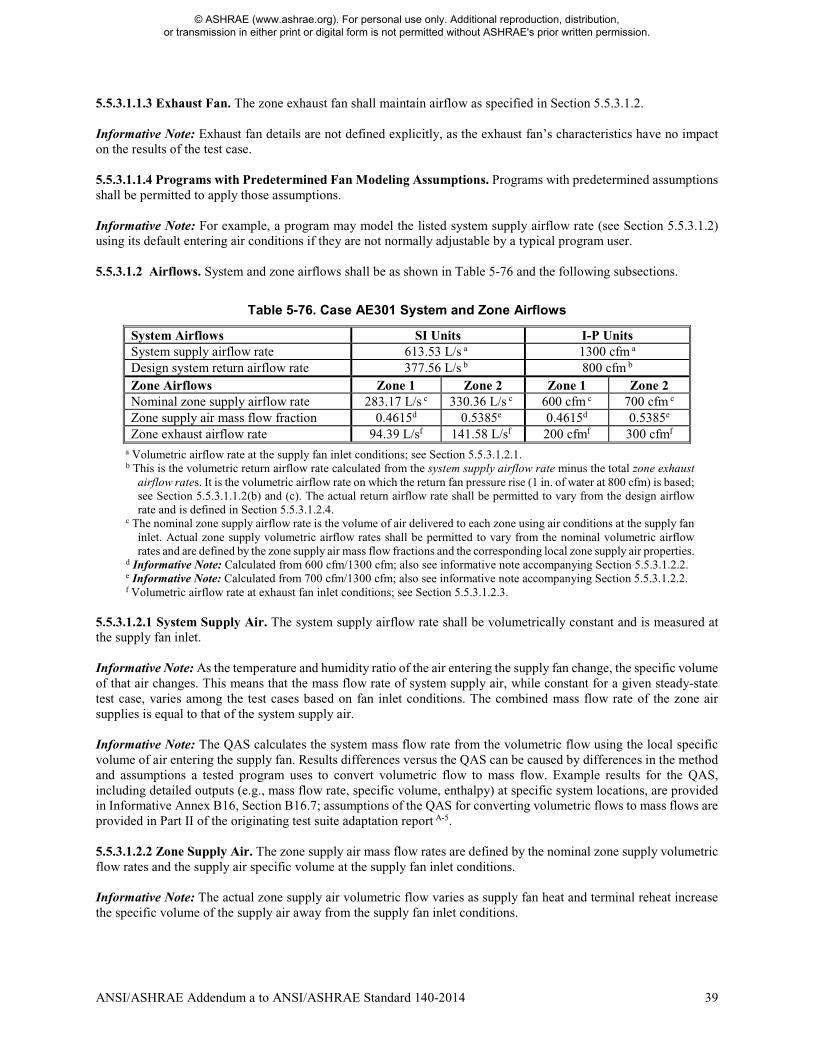
ANSI/ASHRAE Addendum a to ANSI/ASHRAE Standard 140-2014 39
5.5.3.1.1.3 Exhaust Fan. The zone exhaust fan shall maintain airflow as specified in Section 5.5.3.1.2. Informative Note: Exhaust fan details are not defined explicitly, as the exhaust fan’s characteristics have no impact on the results of the test case. 5.5.3.1.1.4 Programs with Predetermined Fan Modeling Assumptions. Programs with predetermined assumptions shall be permitted to apply those assumptions. Informative Note: For example, a program may model the listed system supply airflow rate (see Section 5.5.3.1.2) using its default entering air conditions if they are not normally adjustable by a typical program user. 5.5.3.1.2 Airflows. System and zone airflows shall be as shown in Table 5-76 and the following subsections.
Table 5-76. Case AE301 System and Zone Airflows
System Airflows SI Units I-P Units System supply airflow rate 613.53 L/s a 1300 cfm a Design system return airflow rate 377.56 L/s b 800 cfm b Zone Airflows Zone 1 Zone 2 Zone 1 Zone 2 Nominal zone supply airflow rate 283.17 L/s c 330.36 L/s c 600 cfm c 700 cfm c Zone supply air mass flow fraction 0.4615d 0.5385e 0.4615d 0.5385e Zone exhaust airflow rate 94.39 L/sf 141.58 L/sf 200 cfmf 300 cfmf
a Volumetric airflow rate at the supply fan inlet conditions; see Section 5.5.3.1.2.1. b This is the volumetric return airflow rate calculated from the system supply airflow rate minus the total zone exhaust
airflow rates. It is the volumetric airflow rate on which the return fan pressure rise (1 in. of water at 800 cfm) is based; see Section 5.5.3.1.1.2(b) and (c). The actual return airflow rate shall be permitted to vary from the design airflow rate and is defined in Section 5.5.3.1.2.4.
c The nominal zone supply airflow rate is the volume of air delivered to each zone using air conditions at the supply fan inlet. Actual zone supply volumetric airflow rates shall be permitted to vary from the nominal volumetric airflow rates and are defined by the zone supply air mass flow fractions and the corresponding local zone supply air properties.
d Informative Note: Calculated from 600 cfm/1300 cfm; also see informative note accompanying Section 5.5.3.1.2.2. e Informative Note: Calculated from 700 cfm/1300 cfm; also see informative note accompanying Section 5.5.3.1.2.2. f Volumetric airflow rate at exhaust fan inlet conditions; see Section 5.5.3.1.2.3.
5.5.3.1.2.1 System Supply Air. The system supply airflow rate shall be volumetrically constant and is measured at the supply fan inlet. Informative Note: As the temperature and humidity ratio of the air entering the supply fan change, the specific volume of that air changes. This means that the mass flow rate of system supply air, while constant for a given steady-state test case, varies among the test cases based on fan inlet conditions. The combined mass flow rate of the zone air supplies is equal to that of the system supply air. Informative Note: The QAS calculates the system mass flow rate from the volumetric flow using the local specific volume of air entering the supply fan. Results differences versus the QAS can be caused by differences in the method and assumptions a tested program uses to convert volumetric flow to mass flow. Example results for the QAS, including detailed outputs (e.g., mass flow rate, specific volume, enthalpy) at specific system locations, are provided in Informative Annex B16, Section B16.7; assumptions of the QAS for converting volumetric flows to mass flows are provided in Part II of the originating test suite adaptation report A-5. 5.5.3.1.2.2 Zone Supply Air. The zone supply air mass flow rates are defined by the nominal zone supply volumetric flow rates and the supply air specific volume at the supply fan inlet conditions. Informative Note: The actual zone supply air volumetric flow varies as supply fan heat and terminal reheat increase the specific volume of the supply air away from the supply fan inlet conditions.
© ASHRAE (www.ashrae.org). For personal use only. Additional reproduction, distribution, or transmission in either print or digital form is not permitted without ASHRAE's prior written permission.
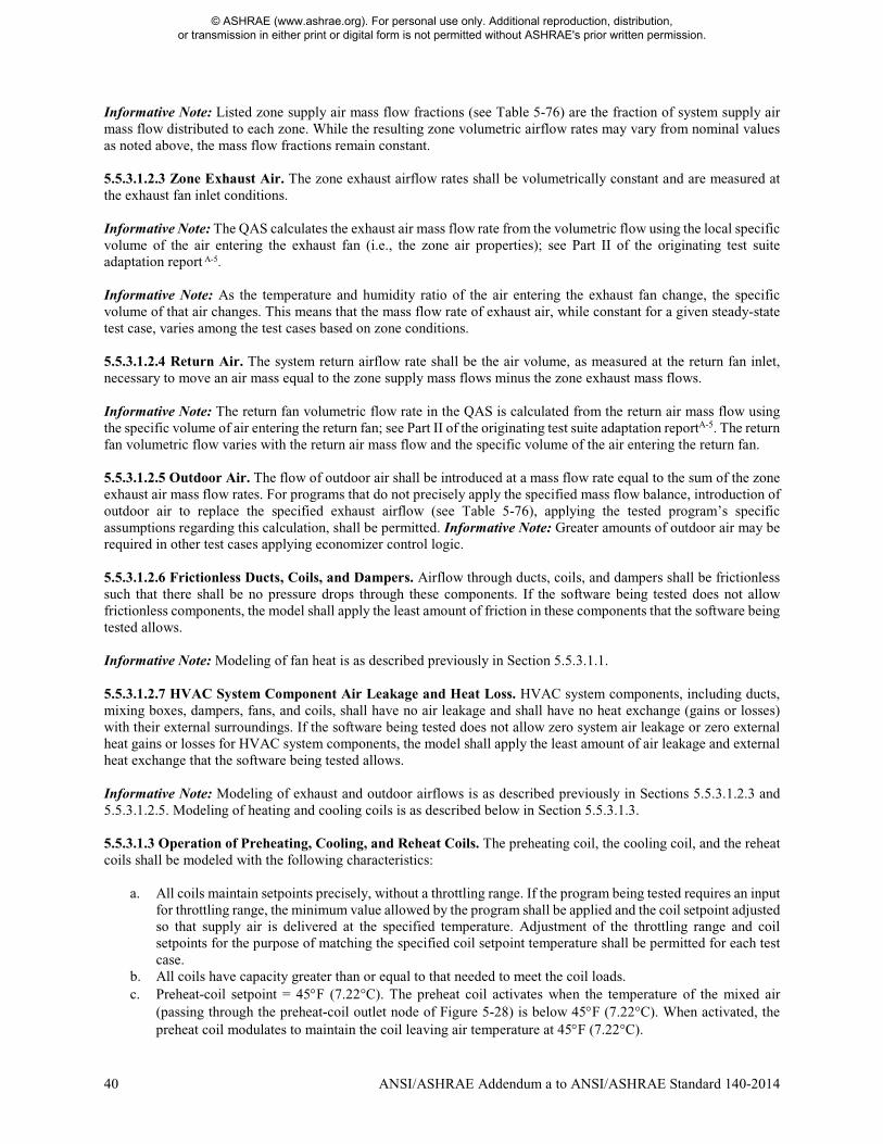
40 ANSI/ASHRAE Addendum a to ANSI/ASHRAE Standard 140-2014
Informative Note: Listed zone supply air mass flow fractions (see Table 5-76) are the fraction of system supply air mass flow distributed to each zone. While the resulting zone volumetric airflow rates may vary from nominal values as noted above, the mass flow fractions remain constant. 5.5.3.1.2.3 Zone Exhaust Air. The zone exhaust airflow rates shall be volumetrically constant and are measured at the exhaust fan inlet conditions. Informative Note: The QAS calculates the exhaust air mass flow rate from the volumetric flow using the local specific volume of the air entering the exhaust fan (i.e., the zone air properties); see Part II of the originating test suite adaptation report A-5. Informative Note: As the temperature and humidity ratio of the air entering the exhaust fan change, the specific volume of that air changes. This means that the mass flow rate of exhaust air, while constant for a given steady-state test case, varies among the test cases based on zone conditions. 5.5.3.1.2.4 Return Air. The system return airflow rate shall be the air volume, as measured at the return fan inlet, necessary to move an air mass equal to the zone supply mass flows minus the zone exhaust mass flows. Informative Note: The return fan volumetric flow rate in the QAS is calculated from the return air mass flow using the specific volume of air entering the return fan; see Part II of the originating test suite adaptation reportA-5. The return fan volumetric flow varies with the return air mass flow and the specific volume of the air entering the return fan. 5.5.3.1.2.5 Outdoor Air. The flow of outdoor air shall be introduced at a mass flow rate equal to the sum of the zone exhaust air mass flow rates. For programs that do not precisely apply the specified mass flow balance, introduction of outdoor air to replace the specified exhaust airflow (see Table 5-76), applying the tested program’s specific assumptions regarding this calculation, shall be permitted. Informative Note: Greater amounts of outdoor air may be required in other test cases applying economizer control logic. 5.5.3.1.2.6 Frictionless Ducts, Coils, and Dampers. Airflow through ducts, coils, and dampers shall be frictionless such that there shall be no pressure drops through these components. If the software being tested does not allow frictionless components, the model shall apply the least amount of friction in these components that the software being tested allows. Informative Note: Modeling of fan heat is as described previously in Section 5.5.3.1.1. 5.5.3.1.2.7 HVAC System Component Air Leakage and Heat Loss. HVAC system components, including ducts, mixing boxes, dampers, fans, and coils, shall have no air leakage and shall have no heat exchange (gains or losses) with their external surroundings. If the software being tested does not allow zero system air leakage or zero external heat gains or losses for HVAC system components, the model shall apply the least amount of air leakage and external heat exchange that the software being tested allows. Informative Note: Modeling of exhaust and outdoor airflows is as described previously in Sections 5.5.3.1.2.3 and 5.5.3.1.2.5. Modeling of heating and cooling coils is as described below in Section 5.5.3.1.3. 5.5.3.1.3 Operation of Preheating, Cooling, and Reheat Coils. The preheating coil, the cooling coil, and the reheat coils shall be modeled with the following characteristics:
a. All coils maintain setpoints precisely, without a throttling range. If the program being tested requires an input for throttling range, the minimum value allowed by the program shall be applied and the coil setpoint adjusted so that supply air is delivered at the specified temperature. Adjustment of the throttling range and coil setpoints for the purpose of matching the specified coil setpoint temperature shall be permitted for each test case.
b. All coils have capacity greater than or equal to that needed to meet the coil loads. c. Preheat-coil setpoint = 45°F (7.22°C). The preheat coil activates when the temperature of the mixed air
(passing through the preheat-coil outlet node of Figure 5-28) is below 45°F (7.22°C). When activated, the preheat coil modulates to maintain the coil leaving air temperature at 45°F (7.22°C).
© ASHRAE (www.ashrae.org). For personal use only. Additional reproduction, distribution, or transmission in either print or digital form is not permitted without ASHRAE's prior written permission.
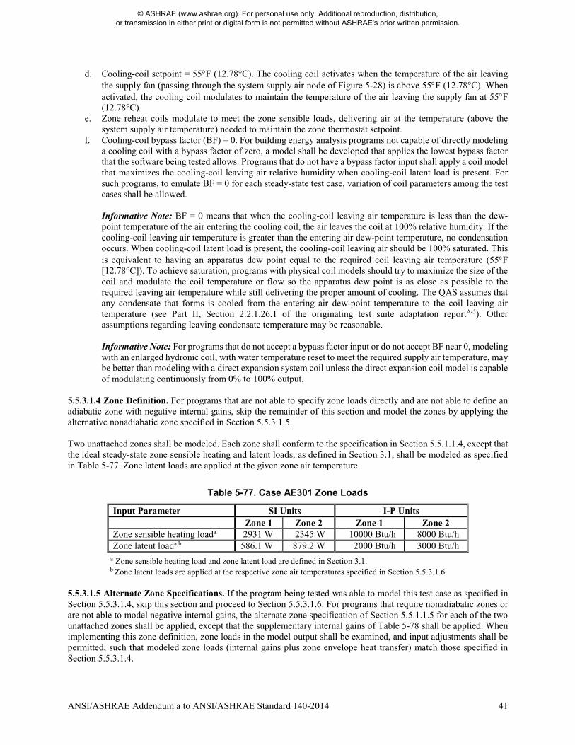
ANSI/ASHRAE Addendum a to ANSI/ASHRAE Standard 140-2014 41
d. Cooling-coil setpoint = 55°F (12.78°C). The cooling coil activates when the temperature of the air leaving the supply fan (passing through the system supply air node of Figure 5-28) is above 55°F (12.78°C). When activated, the cooling coil modulates to maintain the temperature of the air leaving the supply fan at 55°F (12.78°C).
e. Zone reheat coils modulate to meet the zone sensible loads, delivering air at the temperature (above the system supply air temperature) needed to maintain the zone thermostat setpoint.
f. Cooling-coil bypass factor (BF) = 0. For building energy analysis programs not capable of directly modeling a cooling coil with a bypass factor of zero, a model shall be developed that applies the lowest bypass factor that the software being tested allows. Programs that do not have a bypass factor input shall apply a coil model that maximizes the cooling-coil leaving air relative humidity when cooling-coil latent load is present. For such programs, to emulate BF = 0 for each steady-state test case, variation of coil parameters among the test cases shall be allowed. Informative Note: BF = 0 means that when the cooling-coil leaving air temperature is less than the dew-point temperature of the air entering the cooling coil, the air leaves the coil at 100% relative humidity. If the cooling-coil leaving air temperature is greater than the entering air dew-point temperature, no condensation occurs. When cooling-coil latent load is present, the cooling-coil leaving air should be 100% saturated. This is equivalent to having an apparatus dew point equal to the required coil leaving air temperature (55°F [12.78°C]). To achieve saturation, programs with physical coil models should try to maximize the size of the coil and modulate the coil temperature or flow so the apparatus dew point is as close as possible to the required leaving air temperature while still delivering the proper amount of cooling. The QAS assumes that any condensate that forms is cooled from the entering air dew-point temperature to the coil leaving air temperature (see Part II, Section 2.2.1.26.1 of the originating test suite adaptation reportA-5). Other assumptions regarding leaving condensate temperature may be reasonable. Informative Note: For programs that do not accept a bypass factor input or do not accept BF near 0, modeling with an enlarged hydronic coil, with water temperature reset to meet the required supply air temperature, may be better than modeling with a direct expansion system coil unless the direct expansion coil model is capable of modulating continuously from 0% to 100% output.
5.5.3.1.4 Zone Definition. For programs that are not able to specify zone loads directly and are not able to define an adiabatic zone with negative internal gains, skip the remainder of this section and model the zones by applying the alternative nonadiabatic zone specified in Section 5.5.3.1.5. Two unattached zones shall be modeled. Each zone shall conform to the specification in Section 5.5.1.1.4, except that the ideal steady-state zone sensible heating and latent loads, as defined in Section 3.1, shall be modeled as specified in Table 5-77. Zone latent loads are applied at the given zone air temperature.
Table 5-77. Case AE301 Zone Loads
Input Parameter SI Units I-P Units Zone 1 Zone 2 Zone 1 Zone 2 Zone sensible heating loada 2931 W 2345 W 10000 Btu/h 8000 Btu/h Zone latent loada,b 586.1 W 879.2 W 2000 Btu/h 3000 Btu/h
a Zone sensible heating load and zone latent load are defined in Section 3.1. b Zone latent loads are applied at the respective zone air temperatures specified in Section 5.5.3.1.6.
5.5.3.1.5 Alternate Zone Specifications. If the program being tested was able to model this test case as specified in Section 5.5.3.1.4, skip this section and proceed to Section 5.5.3.1.6. For programs that require nonadiabatic zones or are not able to model negative internal gains, the alternate zone specification of Section 5.5.1.1.5 for each of the two unattached zones shall be applied, except that the supplementary internal gains of Table 5-78 shall be applied. When implementing this zone definition, zone loads in the model output shall be examined, and input adjustments shall be permitted, such that modeled zone loads (internal gains plus zone envelope heat transfer) match those specified in Section 5.5.3.1.4.
© ASHRAE (www.ashrae.org). For personal use only. Additional reproduction, distribution, or transmission in either print or digital form is not permitted without ASHRAE's prior written permission.
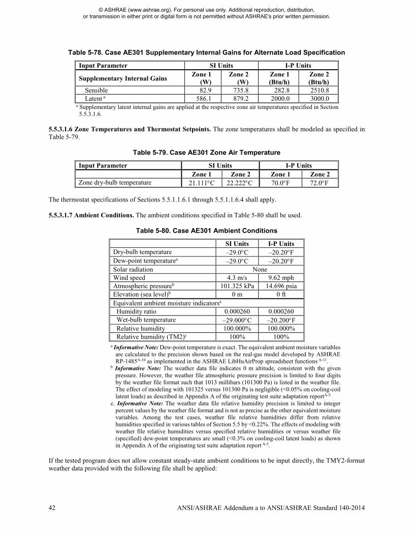
42 ANSI/ASHRAE Addendum a to ANSI/ASHRAE Standard 140-2014
Table 5-78. Case AE301 Supplementary Internal Gains for Alternate Load Specification
Input Parameter SI Units I-P Units
Supplementary Internal Gains Zone 1
(W) Zone 2
(W) Zone 1 (Btu/h)
Zone 2 (Btu/h)
Sensible 82.9 735.8 282.8 2510.8 Latent a 586.1 879.2 2000.0 3000.0
a Supplementary latent internal gains are applied at the respective zone air temperatures specified in Section 5.5.3.1.6.
5.5.3.1.6 Zone Temperatures and Thermostat Setpoints. The zone temperatures shall be modeled as specified in Table 5-79.
Table 5-79. Case AE301 Zone Air Temperature
Input Parameter SI Units I-P Units Zone 1 Zone 2 Zone 1 Zone 2 Zone dry-bulb temperature 21.111°C 22.222°C 70.0°F 72.0°F
The thermostat specifications of Sections 5.5.1.1.6.1 through 5.5.1.1.6.4 shall apply. 5.5.3.1.7 Ambient Conditions. The ambient conditions specified in Table 5-80 shall be used.
Table 5-80. Case AE301 Ambient Conditions
SI Units I-P Units Dry-bulb temperature –29.0°C –20.20°F Dew-point temperaturea –29.0°C –20.20°F Solar radiation None Wind speed 4.3 m/s 9.62 mph Atmospheric pressureb 101.325 kPa 14.696 psia Elevation (sea level)b 0 m 0 ft Equivalent ambient moisture indicatorsa Humidity ratio 0.000260 0.000260 Wet-bulb temperature –29.000°C –20.200°F Relative humidity 100.000% 100.000% Relative humidity (TM2)c 100% 100%
a Informative Note: Dew-point temperature is exact. The equivalent ambient moisture variables are calculated to the precision shown based on the real-gas model developed by ASHRAE RP-1485A-10 as implemented in the ASHRAE LibHuAirProp spreadsheet functions A-11.
b Informative Note: The weather data file indicates 0 m altitude, consistent with the given pressure. However, the weather file atmospheric pressure precision is limited to four digits by the weather file format such that 1013 millibars (101300 Pa) is listed in the weather file. The effect of modeling with 101325 versus 101300 Pa is negligible (<0.05% on cooling-coil latent loads) as described in Appendix A of the originating test suite adaptation reportA-5.
c. Informative Note: The weather data file relative humidity precision is limited to integer percent values by the weather file format and is not as precise as the other equivalent moisture variables. Among the test cases, weather file relative humidities differ from relative humidities specified in various tables of Section 5.5 by <0.22%. The effects of modeling with weather file relative humidities versus specified relative humidities or versus weather file (specified) dew-point temperatures are small (<0.3% on cooling-coil latent loads) as shown in Appendix A of the originating test suite adaptation report A-5.
If the tested program does not allow constant steady-state ambient conditions to be input directly, the TMY2-format weather data provided with the following file shall be applied:
© ASHRAE (www.ashrae.org). For personal use only. Additional reproduction, distribution, or transmission in either print or digital form is not permitted without ASHRAE's prior written permission.
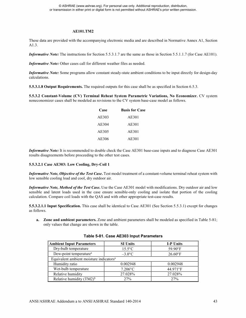
ANSI/ASHRAE Addendum a to ANSI/ASHRAE Standard 140-2014 43
AE101.TM2
These data are provided with the accompanying electronic media and are described in Normative Annex A1, Section A1.3. Informative Note: The instructions for Section 5.5.3.1.7 are the same as those in Section 5.5.1.1.7 (for Case AE101). Informative Note: Other cases call for different weather files as needed. Informative Note: Some programs allow constant steady-state ambient conditions to be input directly for design-day calculations. 5.5.3.1.8 Output Requirements. The required outputs for this case shall be as specified in Section 6.5.3. 5.5.3.2 Constant-Volume (CV) Terminal Reheat System Parametric Variations, No Economizer. CV system noneconomizer cases shall be modeled as revisions to the CV system base-case model as follows.
Case Basis for Case
AE303 AE301
AE304 AE301
AE305 AE301
AE306 AE301
Informative Note: It is recommended to double check the Case AE301 base-case inputs and to diagnose Case AE301 results disagreements before proceeding to the other test cases. 5.5.3.2.1 Case AE303: Low Cooling, Dry-Coil 1 Informative Note, Objective of the Test Case. Test model treatment of a constant-volume terminal reheat system with low sensible cooling load and cool, dry outdoor air. Informative Note, Method of the Test Case. Use the Case AE301 model with modifications. Dry outdoor air and low sensible and latent loads used in the case ensure sensible-only cooling and isolate that portion of the cooling calculation. Compare coil loads with the QAS and with other appropriate test-case results. 5.5.3.2.1.1 Input Specification. This case shall be identical to Case AE301 (See Section 5.5.3.1) except for changes as follows.
a. Zone and ambient parameters. Zone and ambient parameters shall be modeled as specified in Table 5-81; only values that change are shown in the table.
Table 5-81. Case AE303 Input Parameters
Ambient Input Parameters SI Units I-P Units Dry-bulb temperature 15.5°C 59.90°F Dew-point temperaturea –3.0°C 26.60°F
Equivalent ambient moisture indicatorsa Humidity ratio 0.002948 0.002948 Wet-bulb temperature 7.206°C 44.971°F Relative humidity 27.028% 27.028% Relative humidity (TM2)b 27% 27%
© ASHRAE (www.ashrae.org). For personal use only. Additional reproduction, distribution, or transmission in either print or digital form is not permitted without ASHRAE's prior written permission.
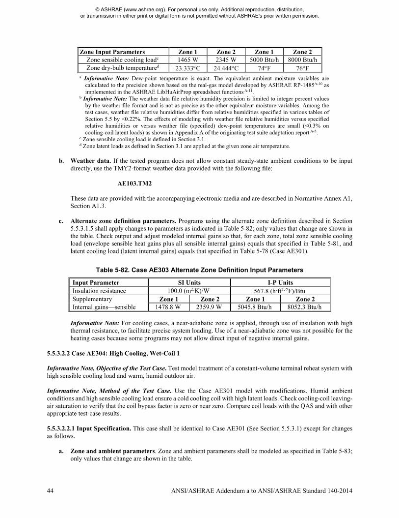
44 ANSI/ASHRAE Addendum a to ANSI/ASHRAE Standard 140-2014
Zone Input Parameters Zone 1 Zone 2 Zone 1 Zone 2 Zone sensible cooling loadc 1465 W 2345 W 5000 Btu/h 8000 Btu/h Zone dry-bulb temperatured 23.333°C 24.444°C 74°F 76°F
a Informative Note: Dew-point temperature is exact. The equivalent ambient moisture variables are calculated to the precision shown based on the real-gas model developed by ASHRAE RP-1485A-10 as implemented in the ASHRAE LibHuAirProp spreadsheet functions A-11.
b Informative Note: The weather data file relative humidity precision is limited to integer percent values by the weather file format and is not as precise as the other equivalent moisture variables. Among the test cases, weather file relative humidities differ from relative humidities specified in various tables of Section 5.5 by <0.22%. The effects of modeling with weather file relative humidities versus specified relative humidities or versus weather file (specified) dew-point temperatures are small (<0.3% on cooling-coil latent loads) as shown in Appendix A of the originating test suite adaptation report A-5.
c Zone sensible cooling load is defined in Section 3.1. d Zone latent loads as defined in Section 3.1 are applied at the given zone air temperature.
b. Weather data. If the tested program does not allow constant steady-state ambient conditions to be input
directly, use the TMY2-format weather data provided with the following file:
AE103.TM2
These data are provided with the accompanying electronic media and are described in Normative Annex A1, Section A1.3.
c. Alternate zone definition parameters. Programs using the alternate zone definition described in Section
5.5.3.1.5 shall apply changes to parameters as indicated in Table 5-82; only values that change are shown in the table. Check output and adjust modeled internal gains so that, for each zone, total zone sensible cooling load (envelope sensible heat gains plus all sensible internal gains) equals that specified in Table 5-81, and latent cooling load (latent internal gains) equals that specified in Table 5-78 (Case AE301).
Table 5-82. Case AE303 Alternate Zone Definition Input Parameters
Input Parameter SI Units I-P Units Insulation resistance 100.0 (m2·K)/W 567.8 (h·ft2·°F)/Btu Supplementary Zone 1 Zone 2 Zone 1 Zone 2 Internal gains—sensible 1478.8 W 2359.9 W 5045.8 Btu/h 8052.3 Btu/h
Informative Note: For cooling cases, a near-adiabatic zone is applied, through use of insulation with high thermal resistance, to facilitate precise system loading. Use of a near-adiabatic zone was not possible for the heating cases because some programs may not allow direct input of negative internal gains.
5.5.3.2.2 Case AE304: High Cooling, Wet-Coil 1 Informative Note, Objective of the Test Case. Test model treatment of a constant-volume terminal reheat system with high sensible cooling load and warm, humid outdoor air. Informative Note, Method of the Test Case. Use the Case AE301 model with modifications. Humid ambient conditions and high sensible cooling load ensure a cold cooling coil with high latent loads. Check cooling-coil leaving-air saturation to verify that the coil bypass factor is zero or near zero. Compare coil loads with the QAS and with other appropriate test-case results. 5.5.3.2.2.1 Input Specification. This case shall be identical to Case AE301 (See Section 5.5.3.1) except for changes as follows.
a. Zone and ambient parameters. Zone and ambient parameters shall be modeled as specified in Table 5-83; only values that change are shown in the table.
© ASHRAE (www.ashrae.org). For personal use only. Additional reproduction, distribution, or transmission in either print or digital form is not permitted without ASHRAE's prior written permission.

ANSI/ASHRAE Addendum a to ANSI/ASHRAE Standard 140-2014 45
Table 5-83. Case AE304 Input Parameters
Ambient Input Parameters SI Units I-P Units Dry-bulb temperature 26.9°C 80.42°F Dew-point temperaturea 22.1°C 71.78°F
Equivalent ambient moisture indicatorsa Humidity ratio 0.016849 0.016849 Wet-bulb temperature 23.441°C 74.194°F Relative humidity 75.023 % 75.023 % Relative humidity (TM2)b 75 % 75 %
Zone Input Parameters Zone 1 Zone 2 Zone 1 Zone 2 Zone sensible cooling loadc 2931 W 3517 W 10000 Btu/h 12000 Btu/h Zone dry-bulb temperatured 23.889°C 25.000°C 75°F 77°F
a Informative Note: Dew-point temperature is exact. The equivalent ambient moisture variables are calculated to the precision shown based on the real-gas model developed by ASHRAE RP-1485A-10 as implemented in the ASHRAE LibHuAirProp spreadsheet functionsA-11.
b Informative Note: The weather data file relative humidity precision is limited to integer percent values by the weather file format and is not as precise as the other equivalent moisture variables. Among the test cases, weather file relative humidities differ from relative humidities specified in various tables of Section 5.5 by <0.22%. The effects of modeling with weather file relative humidities versus specified relative humidities or versus weather file (specified) dew-point temperatures are small (<0.3% on cooling-coil latent loads) as shown in Appendix A of the originating test suite adaptation report A-5.
c Zone sensible cooling load is defined in Section 3.1. d Zone latent loads as defined in Section 3.1 are applied at the given zone air temperature.
b. Weather data. If the tested program does not allow constant steady-state ambient conditions to be input directly, use the TMY2-format weather data provided with the following file:
AE104.TM2
These data are provided with the accompanying electronic media and are described in Normative Annex A1, Section A1.3.
c. Alternate zone definition parameters. Programs using the alternate zone definition described in Section 5.5.3.1.5 shall apply changes to parameters as indicated in Table 5-84; only values that change are shown in the table. Check output and adjust modeled internal gains so that, for each zone, total zone sensible cooling load (envelope sensible heat gains plus all sensible internal gains) equals that specified in Table 5-83, and latent cooling load (latent internal gains) equals that specified in Table 5-78 (Case AE301).
Table 5-84. Case AE304 Alternate Zone Definition Input Parameters
Input Parameter SI Units I-P Units Insulation resistance 100.0 (m2·K)/W 567.8 (h·ft2·°F)/Btu Supplementary internal Zone 1 Zone 2 Zone 1 Zone 2 gains—sensible 2925.6 W 3513.6 W 9982.4 Btu/h 11988.9 Btu/h
5.5.3.2.3 Case AE305: Low Cooling, Dry-Coil 1 Informative Note, Objective of the Test Case. Generate results for a constant-volume terminal reheat system without enthalpy economizer, applying low sensible cooling load and warm, dry outdoor air to compare with results for the same system with enthalpy economizer (Case AE345). Informative Note, Method of the Test Case. Use the Case AE301 model with modifications. Case AE305 applies ambient conditions with low wet-bulb temperature to ensure that the economizer operates when it is specified in Case
© ASHRAE (www.ashrae.org). For personal use only. Additional reproduction, distribution, or transmission in either print or digital form is not permitted without ASHRAE's prior written permission.
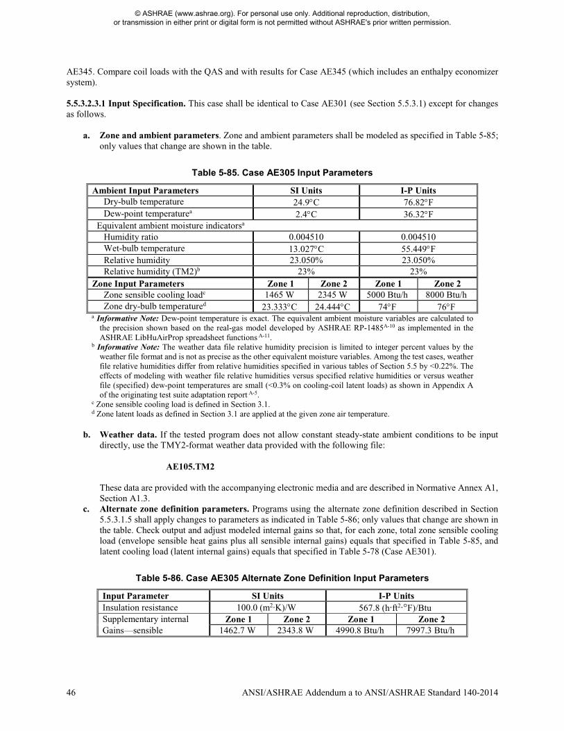
46 ANSI/ASHRAE Addendum a to ANSI/ASHRAE Standard 140-2014
AE345. Compare coil loads with the QAS and with results for Case AE345 (which includes an enthalpy economizer system). 5.5.3.2.3.1 Input Specification. This case shall be identical to Case AE301 (see Section 5.5.3.1) except for changes as follows.
a. Zone and ambient parameters. Zone and ambient parameters shall be modeled as specified in Table 5-85;
only values that change are shown in the table.
Table 5-85. Case AE305 Input Parameters
Ambient Input Parameters SI Units I-P Units Dry-bulb temperature 24.9°C 76.82°F Dew-point temperaturea 2.4°C 36.32°F
Equivalent ambient moisture indicatorsa Humidity ratio 0.004510 0.004510 Wet-bulb temperature 13.027°C 55.449°F Relative humidity 23.050% 23.050% Relative humidity (TM2)b 23% 23%
Zone Input Parameters Zone 1 Zone 2 Zone 1 Zone 2 Zone sensible cooling loadc 1465 W 2345 W 5000 Btu/h 8000 Btu/h Zone dry-bulb temperatured 23.333°C 24.444°C 74°F 76°F
a Informative Note: Dew-point temperature is exact. The equivalent ambient moisture variables are calculated to the precision shown based on the real-gas model developed by ASHRAE RP-1485A-10 as implemented in the ASHRAE LibHuAirProp spreadsheet functions A-11.
b Informative Note: The weather data file relative humidity precision is limited to integer percent values by the weather file format and is not as precise as the other equivalent moisture variables. Among the test cases, weather file relative humidities differ from relative humidities specified in various tables of Section 5.5 by <0.22%. The effects of modeling with weather file relative humidities versus specified relative humidities or versus weather file (specified) dew-point temperatures are small (<0.3% on cooling-coil latent loads) as shown in Appendix A of the originating test suite adaptation report A-5.
c Zone sensible cooling load is defined in Section 3.1. d Zone latent loads as defined in Section 3.1 are applied at the given zone air temperature.
b. Weather data. If the tested program does not allow constant steady-state ambient conditions to be input
directly, use the TMY2-format weather data provided with the following file: AE105.TM2
These data are provided with the accompanying electronic media and are described in Normative Annex A1, Section A1.3.
c. Alternate zone definition parameters. Programs using the alternate zone definition described in Section 5.5.3.1.5 shall apply changes to parameters as indicated in Table 5-86; only values that change are shown in the table. Check output and adjust modeled internal gains so that, for each zone, total zone sensible cooling load (envelope sensible heat gains plus all sensible internal gains) equals that specified in Table 5-85, and latent cooling load (latent internal gains) equals that specified in Table 5-78 (Case AE301).
Table 5-86. Case AE305 Alternate Zone Definition Input Parameters
Input Parameter SI Units I-P Units Insulation resistance 100.0 (m2·K)/W 567.8 (h·ft2·°F)/Btu Supplementary internal Zone 1 Zone 2 Zone 1 Zone 2 Gains—sensible 1462.7 W 2343.8 W 4990.8 Btu/h 7997.3 Btu/h
© ASHRAE (www.ashrae.org). For personal use only. Additional reproduction, distribution, or transmission in either print or digital form is not permitted without ASHRAE's prior written permission.
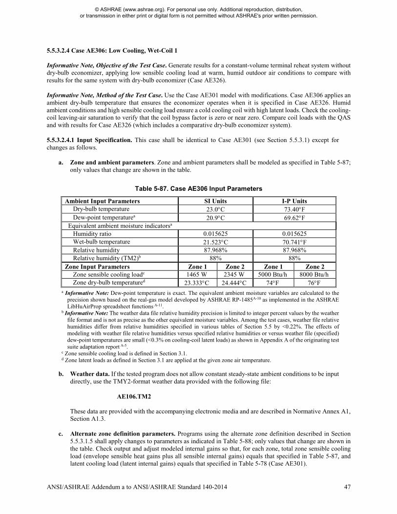
ANSI/ASHRAE Addendum a to ANSI/ASHRAE Standard 140-2014 47
5.5.3.2.4 Case AE306: Low Cooling, Wet-Coil 1 Informative Note, Objective of the Test Case. Generate results for a constant-volume terminal reheat system without dry-bulb economizer, applying low sensible cooling load at warm, humid outdoor air conditions to compare with results for the same system with dry-bulb economizer (Case AE326). Informative Note, Method of the Test Case. Use the Case AE301 model with modifications. Case AE306 applies an ambient dry-bulb temperature that ensures the economizer operates when it is specified in Case AE326. Humid ambient conditions and high sensible cooling load ensure a cold cooling coil with high latent loads. Check the cooling-coil leaving-air saturation to verify that the coil bypass factor is zero or near zero. Compare coil loads with the QAS and with results for Case AE326 (which includes a comparative dry-bulb economizer system). 5.5.3.2.4.1 Input Specification. This case shall be identical to Case AE301 (see Section 5.5.3.1) except for changes as follows.
a. Zone and ambient parameters. Zone and ambient parameters shall be modeled as specified in Table 5-87; only values that change are shown in the table.
Table 5-87. Case AE306 Input Parameters
Ambient Input Parameters SI Units I-P Units Dry-bulb temperature 23.0°C 73.40°F Dew-point temperaturea 20.9°C 69.62°F
Equivalent ambient moisture indicatorsa Humidity ratio 0.015625 0.015625 Wet-bulb temperature 21.523°C 70.741°F Relative humidity 87.968% 87.968% Relative humidity (TM2)b 88% 88%
Zone Input Parameters Zone 1 Zone 2 Zone 1 Zone 2 Zone sensible cooling loadc 1465 W 2345 W 5000 Btu/h 8000 Btu/h Zone dry-bulb temperatured 23.333°C 24.444°C 74°F 76°F
a Informative Note: Dew-point temperature is exact. The equivalent ambient moisture variables are calculated to the precision shown based on the real-gas model developed by ASHRAE RP-1485A-10 as implemented in the ASHRAE LibHuAirProp spreadsheet functions A-11.
b Informative Note: The weather data file relative humidity precision is limited to integer percent values by the weather file format and is not as precise as the other equivalent moisture variables. Among the test cases, weather file relative humidities differ from relative humidities specified in various tables of Section 5.5 by <0.22%. The effects of modeling with weather file relative humidities versus specified relative humidities or versus weather file (specified) dew-point temperatures are small (<0.3% on cooling-coil latent loads) as shown in Appendix A of the originating test suite adaptation report A-5.
c Zone sensible cooling load is defined in Section 3.1. d Zone latent loads as defined in Section 3.1 are applied at the given zone air temperature.
b. Weather data. If the tested program does not allow constant steady-state ambient conditions to be input directly, use the TMY2-format weather data provided with the following file:
AE106.TM2
These data are provided with the accompanying electronic media and are described in Normative Annex A1, Section A1.3.
c. Alternate zone definition parameters. Programs using the alternate zone definition described in Section 5.5.3.1.5 shall apply changes to parameters as indicated in Table 5-88; only values that change are shown in the table. Check output and adjust modeled internal gains so that, for each zone, total zone sensible cooling load (envelope sensible heat gains plus all sensible internal gains) equals that specified in Table 5-87, and latent cooling load (latent internal gains) equals that specified in Table 5-78 (Case AE301).
© ASHRAE (www.ashrae.org). For personal use only. Additional reproduction, distribution, or transmission in either print or digital form is not permitted without ASHRAE's prior written permission.
48 ANSI/ASHRAE Addendum a to ANSI/ASHRAE Standard 140-2014
Table 5-88. Case AE306 Alternate Zone Definition Input Parameters
Input Parameter SI Units I-P Units Insulation resistance 100.0 (m2·K)/W 567.8 (h·ft2·°F)/Btu Supplementary internal Zone 1 Zone 2 Zone 1 Zone 2 Gains—sensible 1465.4 W 2347.0 W 5000.0 Btu/h 8008.4 Btu/h
5.5.3.3 Constant-Volume Terminal Reheat System Parametric Variations, with Economizer Base cases for the CV system economizer cases shall be as follows:
Case Basis for Case
AE326 AE306
AE345 AE305
5.5.3.3.1 Case AE326: Low Cooling, Wet-Coil 1 with Return-Air Comparative Dry-Bulb Economizer Outdoor Air Control. This test case shall be modeled with identical zone and system inputs as Case AE306 except for the existence of a return-air comparative dry-bulb temperature economizer as described below. Informative Note, Objective of the Test Case. Test model treatment of constant-volume terminal reheat air system with return-air comparative dry-bulb temperature economizer at low sensible cooling load and warm, humid outdoor air conditions. Informative Note, Method of the Test Case. Use the Case AE306 model as defined in Section 5.5.3.2.4 and add the economizer as described here. Compare coil loads with the QAS and with results for Case AE306. Informative Note: For the given economizer control logic, at the given steady-state operating conditions, some cooling loads are increased by varying amounts. 5.5.3.3.1.1 Input Specification. Case AE326 shall be identical to Case AE306 (see Section 5.5.3.2.4) except for the addition of a return-air comparative dry-bulb temperature economizer outdoor air control as specified in Section 5.5.3.3.1.1.1. 5.5.3.3.1.1.1 Return-Air Comparative Dry-Bulb Economizer Outdoor Air Control. When the economizer is ON, the outdoor air shall increase until either the cooling-coil sensible load is eliminated or the outdoor air is 100% of the supply airflow; if the economizer control is not able to satisfy the cooling-coil sensible load, the cooling coil shall operate, along with the economizer, to meet the remaining cooling-coil sensible load. The air system dampers (see Figure 5-28) shall be adjusted using economizer control based on outdoor and return air dry-bulb temperature as specified below.
• Economizer = OFF IF ODB > RAT OR ODB ≤ ODBecono,min. In this configuration, the outdoor air mass flow
rate shall equal the combined zone exhaust air mass flows.
o Coil = ON IF SAT > 55°F (12.78°C); see Section 5.5.3.1.3(d).
• Economizer = ON IF RAT ≥ ODB > ODBecono,min.
o Coil = ON IF SAT > 55°F (12.78°C); see Section 5.5.3.1.3(d). In this configuration, the mixed air shall be 100% outdoor air. Informative Note: For the test cases, this condition occurs when RAT ≥ ODB > SFEAT, where SFEAT is the supply fan entering air temperature required to meet the system supply fan leaving air temperature setpoint.
o Coil = OFF IF SAT ≤ 55°F (12.78°C); see Section 5.5.3.1.3(d). In this configuration, the air system
dampers shall modulate the flow of outdoor air to meet the SAT setpoint, and the outdoor airflow shall be permitted to vary from 100% outdoor air to the minimum flow necessary to replace the
© ASHRAE (www.ashrae.org). For personal use only. Additional reproduction, distribution, or transmission in either print or digital form is not permitted without ASHRAE's prior written permission.
ANSI/ASHRAE Addendum a to ANSI/ASHRAE Standard 140-2014 49
combined zone exhaust air mass flows. Informative Note: For the test cases, this condition occurs when ODB ≤ SFEAT.
where for • Economizer = ON, outdoor air shall be provided as needed up to 100% outdoor air but not less than the
minimum required outdoor airflow rate at any time. • Economizer = OFF, outdoor air shall be provided at the minimum required outdoor airflow rate. • Coil = ON, the cooling coil shall operate only as necessary to satisfy the cooling-coil sensible load not
compensated by the economizer. • Coil = OFF, the cooling coil shall not operate.
and where • ODB is the outdoor air dry-bulb temperature. • ODBecono,min is the outdoor dry-bulb temperature where at the minimum required outdoor airflow rate, mixed
air temperature (temperature of air passing through the mixed air node in Figure 5-28) equals the SAT setpoint minus the supply fan temperature rise.
• RAT is the return air dry-bulb temperature at the return fan outlet. • SAT is the supply air dry-bulb temperature at the supply air node (sa); see Figure 5-28. As used above, it is
the supply air temperature if the coil did not operate. Informative Note: Because the cooling coil activates (cooling-coil load occurs) when supply fan leaving air temperature rises above 55°F, an equivalent economizer control scheme is as follows:
• Economizer = OFF AND Coil = ON IF cooling-coil sensible load > 0 and ODB > RAT. In this configuration, the outdoor airflow rate equals the combined zone exhaust airflows.
• Economizer = ON AND Coil = ON IF cooling-coil sensible load > 0 AND ODB ≤ RAT AND all cooling-
coil sensible load is NOT compensated by the economizer. (In this configuration, mixed air is 100% outdoor air.)
• Economizer = ON AND Coil = OFF IF cooling-coil sensible load > 0 AND ODB ≤ RAT AND all cooling-coil sensible load is compensated by the economizer. (In this configuration, the air system dampers modulate so that outdoor airflow is between 100% outdoor air and the minimum flow necessary to replace the combined zone exhaust airflows.)
• Economizer = OFF AND Coil = OFF IF cooling-coil sensible load = 0. 5.5.3.3.2 Case AE345: Low Cooling, Dry-Coil 1 with Return-Air Comparative Enthalpy Economizer Outdoor Air Control This test case shall be modeled with identical zone and system inputs as Case AE305 except for the existence of a return-air comparative enthalpy economizer as described below. Informative Note, Objective of the Test Case. Test model treatment of a constant-volume terminal reheat system with return-air comparative enthalpy economizer at low sensible cooling load and warm, dry outdoor air conditions. Informative Note, Method of the Test Case. Use the Case AE305 model as defined in Section 5.5.3.2.3 and add the economizer as described here. Compare coil loads with the QAS and with results for Case AE305. Informative Note: For the given economizer control logic, at the given steady-state operating conditions, some cooling loads are increased by varying amounts.
© ASHRAE (www.ashrae.org). For personal use only. Additional reproduction, distribution, or transmission in either print or digital form is not permitted without ASHRAE's prior written permission.
50 ANSI/ASHRAE Addendum a to ANSI/ASHRAE Standard 140-2014
5.5.3.3.2.1 Input Specification. Case AE345 shall be identical to Case AE305 (see Section 5.5.3.2.3) except for the addition of a return-air comparative enthalpy economizer outdoor air control as specified in Section 5.5.3.3.2.1.1. 5.5.3.3.2.1.1 Return-Air Comparative Enthalpy Economizer Outdoor Air Control. When the economizer is ON, the outdoor air shall increase until either the cooling-coil sensible load is eliminated or the outdoor air is 100% of the supply airflow; if the economizer control is not able to satisfy the cooling-coil sensible load, the cooling coil shall operate, along with the economizer, to meet the remaining cooling-coil sensible load. The air system dampers (see Figure 5-28) shall be adjusted using economizer control based on outdoor and return air enthalpy as specified below.
• Economizer = OFF IF OAE > RAE OR ODB ≤ ODBecono,min. In this configuration, the outdoor air mass flow rate shall equal the combined zone exhaust air mass flows.
o Coil = ON IF SAT > 55°F (12.78°C); see Section 5.5.3.1.3(d).
• Economizer = ON IF OAE ≤ RAE AND ODB > ODBecono,min.
o Coil = ON IF SAT > 55°F (12.78°C); see Section 5.5.3.1.3(d). In this configuration, the mixed air
shall be 100% outdoor air. Informative Note: For the test cases, this condition occurs when coincident ODB > SFEAT, where SFEAT is the supply fan entering air temperature required to meet the system supply fan leaving air temperature setpoint.
o Coil = OFF IF SAT ≤ 55°F (12.78°C); see Section 5.5.3.1.3(d). In this configuration, the air system
dampers shall modulate the flow of outdoor air to meet the SAT setpoint, and the outdoor airflow shall be permitted to vary from 100% outdoor air to the minimum flow necessary to replace the combined zone exhaust air mass flows. Informative Note: For the test cases, this condition occurs when coincident ODB ≤ SFEAT.
where for • Economizer = ON, outdoor air shall be provided as needed up to 100% outdoor air but not less than the
minimum required outdoor airflow rate at any time. • Economizer = OFF, outdoor air shall be provided at the minimum required outdoor airflow rate. • Coil = ON, the cooling coil shall operate only as necessary to satisfy the cooling-coil sensible load not
compensated by the economizer. • Coil = OFF, the cooling coil shall not operate. and where • OAE is the outdoor air enthalpy. • ODBecono,min is the outdoor dry-bulb temperature where, at the minimum required outdoor airflow rate, mixed
air temperature (temperature of air passing through the mixed air node in Figure 5-28) equals SAT setpoint minus supply fan temperature rise.
• RAE is the return air enthalpy at the return fan outlet. • SAT is the supply air dry-bulb temperature at the supply air node (sa); see Figure 5-28. As used above, it is
the supply air temperature if the coil did not operate. Informative Note: Because the cooling coil activates (cooling-coil load occurs) when supply fan leaving air temperature rises above 55°F, an equivalent economizer control scheme is as follows:
• Economizer = OFF AND Coil = ON IF cooling-coil sensible load > 0 and OAE > RAE.
• Economizer = ON AND Coil = ON IF cooling-coil sensible load > 0 AND OAE ≤ RAE AND all cooling-coil sensible load is NOT compensated by the economizer. (In this configuration, mixed air is 100% outdoor air.)
© ASHRAE (www.ashrae.org). For personal use only. Additional reproduction, distribution, or transmission in either print or digital form is not permitted without ASHRAE's prior written permission.
ANSI/ASHRAE Addendum a to ANSI/ASHRAE Standard 140-2014 51
• Economizer = ON AND Coil = OFF IF cooling-coil sensible load > 0 AND OAE ≤ RAE AND all cooling-coil sensible load is compensated by the economizer. (In this configuration, the air system dampers modulate so that outdoor air is between 100% outdoor air and the minimum flow necessary to replace the combined zone exhaust airflows.)
• Economizer = OFF AND Coil = OFF IF cooling-coil sensible load = 0. 5.5.4 Variable-Air-Volume Terminal Reheat (VAV) System Cases (AE400 Series). The ability to model a variable-air-volume (VAV) air system with zone reheat serving multiple zones shall be tested as described in this section. Informative Note: If the software being tested is capable of applying a variety of system models to address a variable-air-volume system, the system model that is most similar to the system specified for Case AE401 below should be applied and the selected system model should be capable of economizer function; the same selected system should be applied for all of the VAV system test cases. The user may test other possible modeling approaches (available system models) in this context as appropriate to the software being tested. Informative Note: The progression of these test cases follows the AE300 series (CV system) tests. The VAV system serves two zones. 5.5.4.1 Case AE401: Base Case, High-Heating 1 Case AE401 shall be modeled as specified in this section and its subsections. The system configuration shall be modeled as presented in the schematic diagram of Figure 5-29. System input parameters shall be as described in the following sections. Informative Note: The test specifications for the heating, cooling, and reheat coils; zone definition; alternate zone specifications; zone temperature and thermostat setpoints; and ambient conditions (Sections 5.5.4.1.4 through 5.5.4.1.8) are the same as those for the CV system (Sections 5.5.3.1.3 through 5.5.3.1.7). Informative Note, Objective of the Test Case. Test model treatment of a variable-air-volume terminal reheat air system with high sensible heating load and cold outdoor air. Informative Note, Method of the Test Case. A VAV air system conditions two zones that have constant sensible and latent internal loads. The system consists of variable-speed supply and return fans, preheat and cooling coils, and zone variable-air-volume terminals with reheat coils. The cooling coil provides cooling as needed to maintain the supply air temperature setpoint, and the reheat coils provide heating to maintain each zone temperature at its setpoint. The preheat coils operate as needed to prevent supply air temperature from going too far below the supply air temperature setpoint. Zone VAV terminals modulate to provide only the necessary airflow needed to maintain the zone temperature setpoint but not below the zone exhaust airflow rate. The model is run at specified constant outdoor and indoor conditions. Resulting coil loads are compared with the QAS and with other example results (see Informative Annex B16, Section B16.7). The QAS is provided with the accompanying electronic media and is further discussed in Informative Annex B17, Section B17.3. Informative Note: In this base case, no economizer function is modeled; economizer function is tested in later cases.
© ASHRAE (www.ashrae.org). For personal use only. Additional reproduction, distribution, or transmission in either print or digital form is not permitted without ASHRAE's prior written permission.
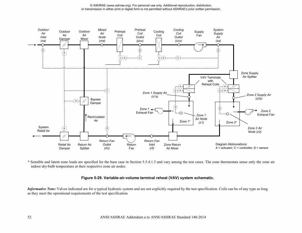
52 ANSI/ASHRAE Addendum a to ANSI/ASHRAE Standard 140-2014
* Sensible and latent zone loads are specified for the base case in Section 5.5.4.1.5 and vary among the test cases. The zone thermostats sense only the zone air
indoor dry-bulb temperature at their respective zone air nodes.
Figure 5-29. Variable-air-volume terminal reheat (VAV) system schematic.
Informative Note: Valves indicated are for a typical hydronic system and are not explicitly required by the test specification. Coils can be of any type as long as they meet the operational requirements of the test specification.
Bypass Damper
Relief Air Damper
Preheat Coil
Cooling Coil
Supply Fan
Zone Return Air Mixer
Zone Supply Air SplitterVAV Terminal
withReheat Coils
Zone 1* Zone 2*
Return Fan
c c
A
A
A
A C
S
A C
S
C
S
S
Outdoor Air
Inlet(oa)
Mixed Air
Node(ma)
PreheatCoil
Outlet(pco)
Cooling Coil
Outlet(cco)
SystemSupply
Air(sa)
Zone 2 Supply Air (z2s)
Zone 2 Exhaust Fan
Recirculated Air
Zone 2 Air Node (z2)
Zone 1 Supply Air (z1s)
Zone 1 Air Node
(z1)
Zone 1 Exhaust Fan
Return Fan Inlet(rfi)
Return Fan Outlet(rfo)
SystemRelief Air
Outdoor Air
Damper
S S
Return Air Splitter
Outdoor Air
Mixer
A A
A A
Diagram Abbreviations: A = actuator; C = controller; S = sensor
VAV Terminals with
Reheat Coils
© ASHRAE (www.ashrae.org). For personal use only. Additional reproduction, distribution, or transmission in either print or digital form is not permitted without ASHRAE's prior written permission.
ANSI/ASHRAE Addendum a to ANSI/ASHRAE Standard 140-2014 53
5.5.4.1.1 Fan Operation. The system shall have a supply fan, return fan, and individual zone exhaust fans. 5.5.4.1.1.1 Supply Fan. The supply fan characteristics shall be as follows:
a. The fan is located downstream of the heating and cooling coils as specified in Figure 5-29. b. The supply fan total pressure rise = 2.0 in. of water (498 Pa) at 1300 cfm (613.53 L/s). c. The supply fan total pressure rise varies as
Pressure rise (in. of water) = 2.0 in. of water × [(Actual supply fan cfm)/(1300 cfm)]2. d. The fan modulates to provide the airflow established by the zone VAV terminals as specified in Section
5.5.4.1.3. e. The fan operates continuously. f. Fan energy is transferred to the air that is being moved. g. Fan motor and transmission drive energy loss is not transferred to the moving air. h. (Fan heat to airstream) = Ho × [1/(Fan mechanical efficiency) – 1], where
• Ho is the fan output power required to meet the specified airflow requirements; see Ho under fan mechanical efficiency in Section 3.1.
• Fan mechanical efficiency = 0.7, constant value; fan mechanical efficiency is defined in Section 3.1. i. (Fan motor input power) = Ho/[(Fan mechanical efficiency) × (Transmission drive efficiency) × (Motor
efficiency)], where • 0 ≤ (Transmission drive efficiency) ≤ 1; transmission drive efficiency is defined in Section 3.1. • 0 ≤ (Motor efficiency) ≤ 1; motor efficiency is defined in Section 3.1.
If the program being tested is not able to model the transmission drive and motor losses as occurring outside the airstream, the fan, transmission drive, and motor efficiency losses shall be specified to have a combined efficiency of 0.7 and to occur in the airstream. Informative Note: The airstream heat gain (fan heat) affects the test-case outputs, while the motor and transmission drive input energy do not; therefore, the transmission and motor efficiency may be any value as long as their heat is not imparted to the airstream and the fan mechanical efficiency = 0.7.
5.5.4.1.1.2 Return Fan. The return fan characteristics shall be as follows:
a. The fan is located downstream of the zone return air mixer, and before the return air splitter, as specified in Figure 5-29.
b. The return fan total pressure rise = 1.0 in. of water (249 Pa) at 800 cfm (377.56 L/s). c. The return fan total pressure rise varies as
Pressure rise (in. of water) = 1.0 in. of water × [(Actual return fan cfm)/(800 cfm)]2. d. The fan modulates to return an air volume as specified in Section 5.5.4.1.2.4. e. The fan operates continuously. f. Fan energy is transferred to the air that is being moved. g. Fan motor and transmission drive energy loss is not transferred to the moving air. h. (Fan heat to airstream) = Ho × [1/(Fan mechanical efficiency) – 1], where
• Ho is the fan output power required to meet the specified airflow requirements; see Ho under fan mechanical efficiency in Section 3.1.
• Fan mechanical efficiency = 0.7, constant value; fan mechanical efficiency is defined in Section 3.1. i. (Fan motor input power) = Ho/[(Fan mechanical efficiency) × (Transmission drive efficiency) × (Motor
efficiency)], where • 0 ≤ (Transmission drive efficiency) ≤ 1; transmission drive efficiency is defined in Section 3.1. • 0 ≤ (Motor efficiency) ≤ 1; motor efficiency is defined in Section 3.1.
If the program being tested is not able to model the transmission drive and motor losses as occurring outside the airstream, the fan, transmission drive, and motor efficiency losses shall be specified to have a combined efficiency of 0.7 and to occur in the airstream.
© ASHRAE (www.ashrae.org). For personal use only. Additional reproduction, distribution, or transmission in either print or digital form is not permitted without ASHRAE's prior written permission.

54 ANSI/ASHRAE Addendum a to ANSI/ASHRAE Standard 140-2014
Informative Note: The airstream heat gain (fan heat) affects the test-case outputs, while the motor and transmission drive input energy do not; therefore, the transmission and motor efficiency may be any value as long as their heat is not imparted to the airstream and the fan mechanical efficiency = 0.7.
5.5.4.1.1.3 Exhaust Fan. The zone exhaust fan shall maintain airflow as specified in Section 5.5.4.1.2. Informative Note: Exhaust fan details are not defined explicitly, as the exhaust fan’s characteristics have no impact on the results of the test case. 5.5.4.1.1.4 Programs with Predetermined Fan Modeling Assumptions. Programs with predetermined assumptions shall be permitted to apply those assumptions. Informative Note: For example, a program may model the listed system supply airflow rate (see Section 5.5.4.1.2) using its default entering air conditions if they are not normally adjustable by a typical program user. 5.5.4.1.2 Airflows. System and zone airflows shall be as shown in Table 5-89 and the following subsections.
Table 5-89 Case AE401 System Airflow Rates
System Airflows SI Units I-P Units Design system supply airflow rate 613.53 L/sa 1300 cfma Design system return airflow rate 377.56 L/sb 800 cfmb Zone Airflows Zone 1 Zone 2 Zone 1 Zone 2 Design nominal zone supply airflow rate 283.17 L/sc 330.36 L/sc 600 cfmc 700 cfmc Design zone minimum airflow rate 94.39 L/sd 141.58 L/sd 200 cfmd 300 cfmd
Design zone minimum airflow fraction (% of design nominal zone supply air)
33%d,e 43%d,f 33%d,e 43%d,f
Zone exhaust airflow rate 94.39 L/sg 141.58 L/sg 200 cfmg 300 cfmg a This is the volumetric airflow rate on which the supply fan pressure rise (2 in. of water at 1300 cfm) is based; see
Section 5.5.4.1.1.1(b) and (c). The actual system supply airflow rate shall be permitted to vary from the design system supply airflow rate and is defined in Section 5.5.4.1.2.1.
b This is the volumetric return airflow rate calculated from the design system supply airflow rate minus the total zone exhaust airflow rates. It is the volumetric airflow rate on which the return fan pressure rise (1 in. of water at 800 cfm) is based; see Section 5.5.4.1.1.2(b) and (c). The actual return airflow rate shall be permitted to vary from the design airflow rate and is defined in Section 5.5.4.1.2.4.
c The design nominal zone supply airflow rate is the maximum volume of air entering the zone at the outlet of the VAV terminal, using air conditions at the supply fan inlet. Any design zone supply airflow rate shall be permitted as long as zone sensible loads are satisfied. Actual zone supply volumetric airflow rates shall be permitted to vary according to zone VAV terminal requirements (see Section 5.5.4.1.3). Informative Note: At design conditions, the actual zone supply air volumetric flow varies as supply fan heat increases the specific volume of the air away from the supply fan inlet. Use of the values in this table ensures adequate capacity for the specified test cases.
d Informative Note: Design zone minimum airflow rate and minimum airflow fraction are approximate equivalent inputs provided for those programs that may need them. The actual zone minimum airflow rate equals the zone exhaust air mass flow rate. Programs that require volumetric inputs for the zone minimum airflow and do not calculate volumetric airflows based on system-specific local conditions (e.g., zone exhaust at zone air conditions, supply air at supply fan entering air conditions) may use the listed values. Because zone conditions and supply fan entering air temperature vary among the test cases, the actual minimum zone air mass flow rates and volumetric flow rates, as calculated by the QAS, also vary among the test cases.
e Informative Note: Zone (VAV terminal) minimum airflow fraction; listed approximate value is calculated from 200 cfm/600 cfm. A more precise value can be obtained from the ratio of the mass flows.
f Informative Note: Zone (VAV terminal) minimum airflow fraction; listed approximate value is calculated from 300 cfm/700 cfm. A more precise value can be obtained from the ratio of the mass flows.
g Volumetric airflow rate at exhaust fan inlet conditions; see Section 5.5.4.1.2.3.
© ASHRAE (www.ashrae.org). For personal use only. Additional reproduction, distribution, or transmission in either print or digital form is not permitted without ASHRAE's prior written permission.
ANSI/ASHRAE Addendum a to ANSI/ASHRAE Standard 140-2014 55
Informative Note: The design system supply and return airflow rates and design zone supply airflow rates are the same as the designated constant-volume airflow rates of Case AE301. For the VAV system cases, the actual system supply and return airflow rates and the zone supply airflow rates vary in response to the operation of VAV terminals. 5.5.4.1.2.1 System Supply Air. The system supply airflow rate shall deliver the airflow required to satisfy the combined VAV terminal airflow requirements of Zones 1 and 2; see Section 5.5.4.1.3 for VAV terminal operation requirements. Informative Note: The system supply mass flow rate is equal to the combined mass flow rate of the zone air supplies. Informative Note: As the temperature and humidity ratio of the air entering the supply fan change, the specific volume of that air changes. Informative Note: The QAS calculates the system mass flow rate from the volumetric flow using the local specific volume of air entering the supply fan. Results differences versus the QAS can be caused by differences in the method and assumptions a tested program uses to convert volumetric flow to mass flow. Example results for the QAS, including detailed outputs (e.g., mass flow rate, specific volume, enthalpy) at specific system locations, are provided in Informative Annex B16, Section B16.7; assumptions of the QAS for converting volumetric flows to mass flows are provided in Part II of the originating test suite adaptation report A-5. 5.5.4.1.2.2 Zone Supply Air. The zone supply airflow rates shall be those required to meet the VAV terminal airflow requirements, see Section 5.5.4.1.3(b), (c), (d), and (f). 5.5.4.1.2.3 Zone Exhaust Air. The zone exhaust airflow rates shall be volumetrically constant and are measured at the exhaust fan inlet conditions. Informative Note: The QAS calculates the exhaust air mass flow rate from the volumetric flow using the local specific volume of the air entering the exhaust fan (i.e., the zone air properties); see Part II of the originating test suite adaptation reportA-5. Informative Note: As the temperature and humidity ratio of the air entering the exhaust fan change, the specific volume of that air changes. This means that the mass flow rate of exhaust air, while constant for a given steady-state test case, varies among the test cases based on zone conditions. 5.5.4.1.2.4 Return Air. The system return airflow rate shall be the air volume, as measured at the return fan inlet, necessary to move an air mass equal to the zone supply mass flows minus the zone exhaust mass flows. Informative Note: When the VAV terminals are at minimum position, defined as that needed to offset zone exhaust (Section 5.5.4.1.3[c]), there is zero return airflow. Informative Note: The return fan volumetric flow rate in the QAS is calculated from the return air mass flow using the specific volume of air entering the return fan; see Part II of the originating test suite adaptation reportA-5. The return fan volumetric flow varies with the return air mass flow and the specific volume of the air entering the return fan. 5.5.4.1.2.5 Outdoor Air. The flow of outdoor air shall be introduced at a mass flow rate equal to the sum of the zone exhaust air mass flow rates. For programs that do not precisely apply the specified mass flow balance, introduction of outdoor air to replace the specified exhaust airflow (see Table 5-89), applying the tested program’s specific assumptions regarding this calculation, shall be permitted. Informative Note: Greater amounts of outdoor air may be required in other test cases applying economizer control logic. 5.5.4.1.2.6 Frictionless Ducts, Coils, and Dampers. Airflow through ducts, coils, and dampers shall be frictionless, such that there shall be no pressure drops through these components. If the software being tested does not allow frictionless components, the model shall apply the least amount of friction in these components that the software being tested allows. Informative Note: Modeling of fan heat is as described previously in Section 5.5.4.1.1.
© ASHRAE (www.ashrae.org). For personal use only. Additional reproduction, distribution, or transmission in either print or digital form is not permitted without ASHRAE's prior written permission.
56 ANSI/ASHRAE Addendum a to ANSI/ASHRAE Standard 140-2014
5.5.4.1.2.7 HVAC System Component Air Leakage and Heat Loss. HVAC system components, including ducts, mixing boxes, dampers, fans, and coils, shall have no air leakage and shall have no heat exchange (gains or losses) with their external surroundings. If the software being tested does not allow zero system air leakage or zero external heat gains or losses for HVAC system components, the model shall apply the least amount of air leakage and external heat exchange that the software being tested allows. Informative Note: Modeling of exhaust and outdoor airflows is as described previously in Sections 5.5.4.1.2.3 and 5.5.4.1.2.5. Modeling of heating and cooling coils is as described below in Section 5.5.4.1.4. 5.5.4.1.3 Operation of VAV Terminals. Zone VAV terminals shall operate as follows:
a. Zone VAV terminals are controlled by zone thermostats and maintain zone setpoints precisely without a throttling range or dead band.
b. Zone VAV terminals shall have airflow capacity and reheat coil heating capacity greater than or equal to those needed to meet the space conditioning requirements of the test case.
c. The VAV terminal dampers shall reduce the zone supply airflows to the zone minimum required airflow rates unless zone space cooling requires higher flows.
d. The VAV terminal minimum airflow rate for each zone shall equal the given zone’s exhaust fan mass flow rate. Informative Note: The minimum required zone airflow rates are those needed to replace the respective zone exhaust fan airflows. Because the exhaust mass flow rates change with zone (exhaust fan inlet) conditions, the VAV terminal minimum mass flow rate also changes.
e. If the minimum zone supply airflow causes a zone temperature to drop below the zone temperature setpoint, the reheat coil shall modulate to maintain the zone temperature setpoint. At all other conditions, the reheat coil shall be OFF.
f. If the minimum zone supply airflow causes a zone temperature to rise above the zone temperature setpoint, the VAV terminal damper shall modulate (open further) to increase the flow of supply air to the zone as required to maintain the zone space cooling setpoint. Informative Note: If input values are needed for a maximum or design VAV terminal flow rate, the design nominal zone supply airflow rates provided in Table 5-89 may be used; at the design condition, the VAV terminal dampers are in the fully open position. The current test cases do not require operation at or above 100% design conditions.
5.5.4.1.4 Operation of Preheating, Cooling, and Reheat Coils. The preheating coil, the cooling coil, and the reheat coils shall be modeled as specified for the CV system test base case in Section 5.5.3.1.3. 5.5.4.1.5 Zone Definition. For programs that are not able to specify zone loads directly and are not able to define an adiabatic zone with negative internal gains, skip the remainder of this section and model the zone by applying the alternative nonadiabatic zone specified in Section 5.5.4.1.6. Two unattached zones shall be modeled as specified for the CV system test base case in Section 5.5.3.1.4. 5.5.4.1.6 Alternate Zone Specifications. If the program being tested was able to model this test case as specified in Section 5.5.4.1.5, skip this section and proceed to Section 5.5.4.1.7. For programs that require nonadiabatic zones or are not able to model negative internal gains, the alternate zone specification for the CV system test base case in Section 5.5.3.1.5 shall be applied. 5.5.4.1.7 Zone Temperatures and Thermostat Setpoints. These shall be the same as for the CV system test base case as specified in Section 5.5.3.1.6. 5.5.4.1.8 Ambient Conditions. The ambient conditions shall be the same as for the CV system test base case as specified in Section 5.5.3.1.7. 5.5.4.1.9 Output Requirements. The required outputs for this case shall be as specified in Section 6.5.4. 5.5.4.2 VAV Terminal Reheat System Parametric Variations, No Economizer. VAV system noneconomizer cases shall be modeled as revisions to the VAV system base-case model as follows.
© ASHRAE (www.ashrae.org). For personal use only. Additional reproduction, distribution, or transmission in either print or digital form is not permitted without ASHRAE's prior written permission.
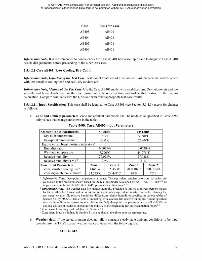
ANSI/ASHRAE Addendum a to ANSI/ASHRAE Standard 140-2014 57
Case Basis for Case
AE403 AE401
AE404 AE401
AE405 AE401
AE406 AE401
Informative Note: It is recommended to double check the Case AE401 base-case inputs and to diagnose Case AE401 results disagreements before proceeding to the other test cases. 5.5.4.2.1 Case AE403: Low Cooling, Dry-Coil 1 Informative Note, Objective of the Test Case. Test model treatment of a variable-air-volume terminal reheat system with low sensible cooling load and cool, dry outdoor air. Informative Note, Method of the Test Case. Use the Case AE401 model with modifications. Dry outdoor air and low sensible and latent loads used in the case ensure sensible only cooling and isolate that portion of the cooling calculation. Compare coil loads with the QAS and with other appropriate test-case results. 5.5.4.2.1.1 Input Specification. This case shall be identical to Case AE401 (see Section 5.5.4.1) except for changes as follows.
a. Zone and ambient parameters. Zone and ambient parameters shall be modeled as specified in Table 5-90;
only values that change are shown in the table.
Table 5-90. Case AE403 Input Parameters
Ambient Input Parameters SI Units I-P Units Dry-bulb temperature 15.5°C 59.90°F Dew-point temperaturea –3.0°C 26.60°F
Equivalent ambient moisture indicatorsa Humidity ratio 0.002948 0.002948 Wet-bulb temperature 7.206°C 44.971°F Relative humidity 27.028% 27.028% Relative humidity (TM2)b 27% 27%
Zone Input Parameters Zone 1 Zone 2 Zone 1 Zone 2 Zone sensible cooling loadc 1465 W 2345 W 5000 Btu/h 8000 Btu/h Zone dry-bulb temperatured 23.333°C 24.444°C 74°F 76°F
a Informative Note: Dew-point temperature is exact. The equivalent ambient moisture variables are calculated to the precision shown based on the real-gas model developed by ASHRAE RP-1485A-10 as implemented in the ASHRAE LibHuAirProp spreadsheet functions A-11.
b Informative Note: The weather data file relative humidity precision is limited to integer percent values by the weather file format and is not as precise as the other equivalent moisture variables. Among the test cases, weather file relative humidities differ from relative humidities specified in various tables of Section 5.5 by <0.22%. The effects of modeling with weather file relative humidities versus specified relative humidities or versus weather file (specified) dew-point temperatures are small (<0.3% on cooling-coil latent loads) as shown in Appendix A of the originating test suite adaptation reportA-5.
c Zone sensible cooling load is defined in Section 3.1. d Zone latent loads as defined in Section 3.1 are applied at the given zone air temperature.
b. Weather data. If the tested program does not allow constant steady-state ambient conditions to be input directly, use the TMY2-format weather data provided with the following file:
AE103.TM2
© ASHRAE (www.ashrae.org). For personal use only. Additional reproduction, distribution, or transmission in either print or digital form is not permitted without ASHRAE's prior written permission.
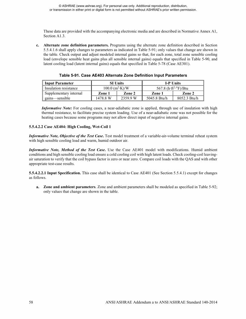
58 ANSI/ASHRAE Addendum a to ANSI/ASHRAE Standard 140-2014
These data are provided with the accompanying electronic media and are described in Normative Annex A1, Section A1.3.
c. Alternate zone definition parameters. Programs using the alternate zone definition described in Section 5.5.4.1.6 shall apply changes to parameters as indicated in Table 5-91; only values that change are shown in the table. Check output and adjust modeled internal gains so that, for each zone, total zone sensible cooling load (envelope sensible heat gains plus all sensible internal gains) equals that specified in Table 5-90, and latent cooling load (latent internal gains) equals that specified in Table 5-78 (Case AE301).
Table 5-91. Case AE403 Alternate Zone Definition Input Parameters
Input Parameter SI Units I-P Units Insulation resistance 100.0 (m2·K)/W 567.8 (h·ft2·°F)/Btu Supplementary internal Zone 1 Zone 2 Zone 1 Zone 2 gains—sensible 1478.8 W 2359.9 W 5045.8 Btu/h 8052.3 Btu/h
Informative Note: For cooling cases, a near-adiabatic zone is applied, through use of insulation with high thermal resistance, to facilitate precise system loading. Use of a near-adiabatic zone was not possible for the heating cases because some programs may not allow direct input of negative internal gains.
5.5.4.2.2 Case AE404: High Cooling, Wet-Coil 1 Informative Note, Objective of the Test Case. Test model treatment of a variable-air-volume terminal reheat system with high sensible cooling load and warm, humid outdoor air. Informative Note, Method of the Test Case. Use the Case AE401 model with modifications. Humid ambient conditions and high sensible cooling load ensure a cold cooling coil with high latent loads. Check cooling-coil leaving-air saturation to verify that the coil bypass factor is zero or near zero. Compare coil loads with the QAS and with other appropriate test-case results. 5.5.4.2.2.1 Input Specification. This case shall be identical to Case AE401 (See Section 5.5.4.1) except for changes as follows.
a. Zone and ambient parameters. Zone and ambient parameters shall be modeled as specified in Table 5-92; only values that change are shown in the table.
© ASHRAE (www.ashrae.org). For personal use only. Additional reproduction, distribution, or transmission in either print or digital form is not permitted without ASHRAE's prior written permission.
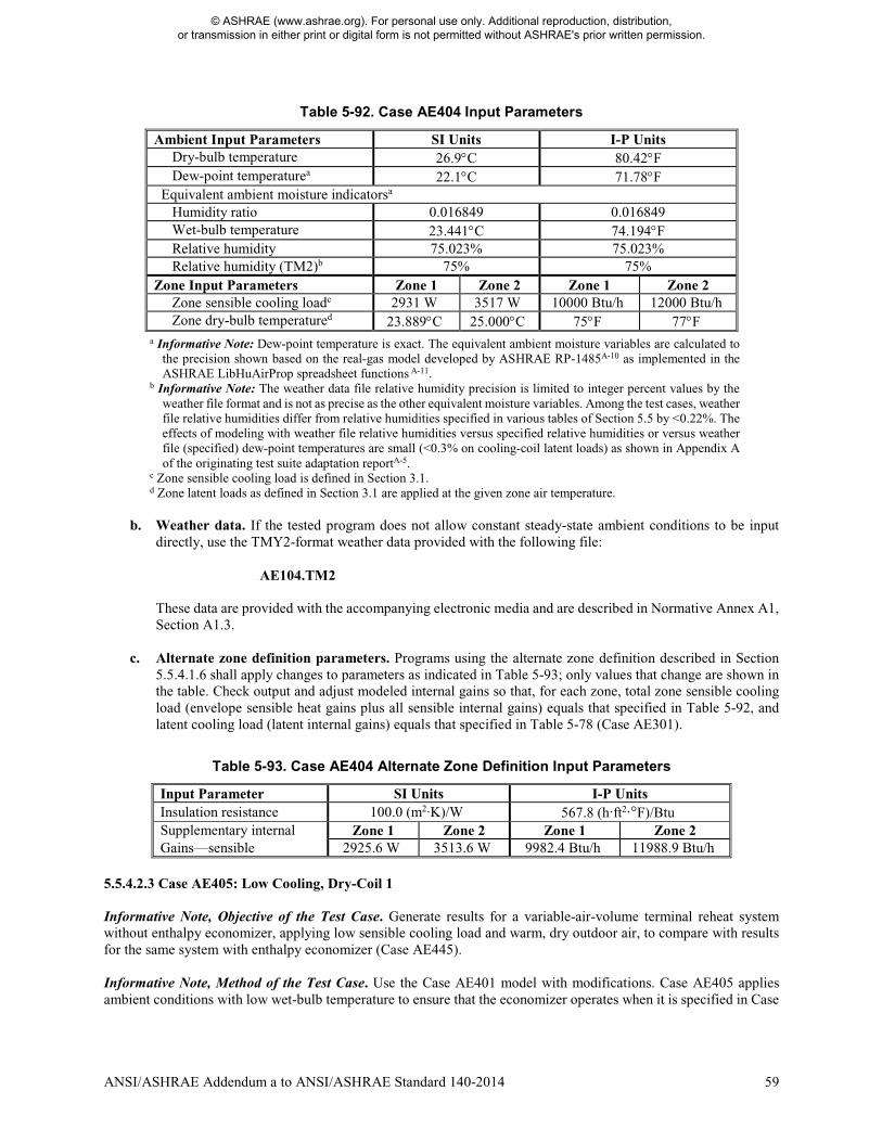
ANSI/ASHRAE Addendum a to ANSI/ASHRAE Standard 140-2014 59
Table 5-92. Case AE404 Input Parameters
Ambient Input Parameters SI Units I-P Units Dry-bulb temperature 26.9°C 80.42°F Dew-point temperaturea 22.1°C 71.78°F
Equivalent ambient moisture indicatorsa Humidity ratio 0.016849 0.016849 Wet-bulb temperature 23.441°C 74.194°F Relative humidity 75.023% 75.023% Relative humidity (TM2)b 75% 75%
Zone Input Parameters Zone 1 Zone 2 Zone 1 Zone 2 Zone sensible cooling loadc 2931 W 3517 W 10000 Btu/h 12000 Btu/h Zone dry-bulb temperatured 23.889°C 25.000°C 75°F 77°F
a Informative Note: Dew-point temperature is exact. The equivalent ambient moisture variables are calculated to the precision shown based on the real-gas model developed by ASHRAE RP-1485A-10 as implemented in the ASHRAE LibHuAirProp spreadsheet functions A-11.
b Informative Note: The weather data file relative humidity precision is limited to integer percent values by the weather file format and is not as precise as the other equivalent moisture variables. Among the test cases, weather file relative humidities differ from relative humidities specified in various tables of Section 5.5 by <0.22%. The effects of modeling with weather file relative humidities versus specified relative humidities or versus weather file (specified) dew-point temperatures are small (<0.3% on cooling-coil latent loads) as shown in Appendix A of the originating test suite adaptation reportA-5.
c Zone sensible cooling load is defined in Section 3.1. d Zone latent loads as defined in Section 3.1 are applied at the given zone air temperature.
b. Weather data. If the tested program does not allow constant steady-state ambient conditions to be input
directly, use the TMY2-format weather data provided with the following file: AE104.TM2
These data are provided with the accompanying electronic media and are described in Normative Annex A1, Section A1.3.
c. Alternate zone definition parameters. Programs using the alternate zone definition described in Section 5.5.4.1.6 shall apply changes to parameters as indicated in Table 5-93; only values that change are shown in the table. Check output and adjust modeled internal gains so that, for each zone, total zone sensible cooling load (envelope sensible heat gains plus all sensible internal gains) equals that specified in Table 5-92, and latent cooling load (latent internal gains) equals that specified in Table 5-78 (Case AE301).
Table 5-93. Case AE404 Alternate Zone Definition Input Parameters
Input Parameter SI Units I-P Units Insulation resistance 100.0 (m2·K)/W 567.8 (h·ft2·°F)/Btu Supplementary internal Zone 1 Zone 2 Zone 1 Zone 2 Gains—sensible 2925.6 W 3513.6 W 9982.4 Btu/h 11988.9 Btu/h
5.5.4.2.3 Case AE405: Low Cooling, Dry-Coil 1 Informative Note, Objective of the Test Case. Generate results for a variable-air-volume terminal reheat system without enthalpy economizer, applying low sensible cooling load and warm, dry outdoor air, to compare with results for the same system with enthalpy economizer (Case AE445). Informative Note, Method of the Test Case. Use the Case AE401 model with modifications. Case AE405 applies ambient conditions with low wet-bulb temperature to ensure that the economizer operates when it is specified in Case
© ASHRAE (www.ashrae.org). For personal use only. Additional reproduction, distribution, or transmission in either print or digital form is not permitted without ASHRAE's prior written permission.
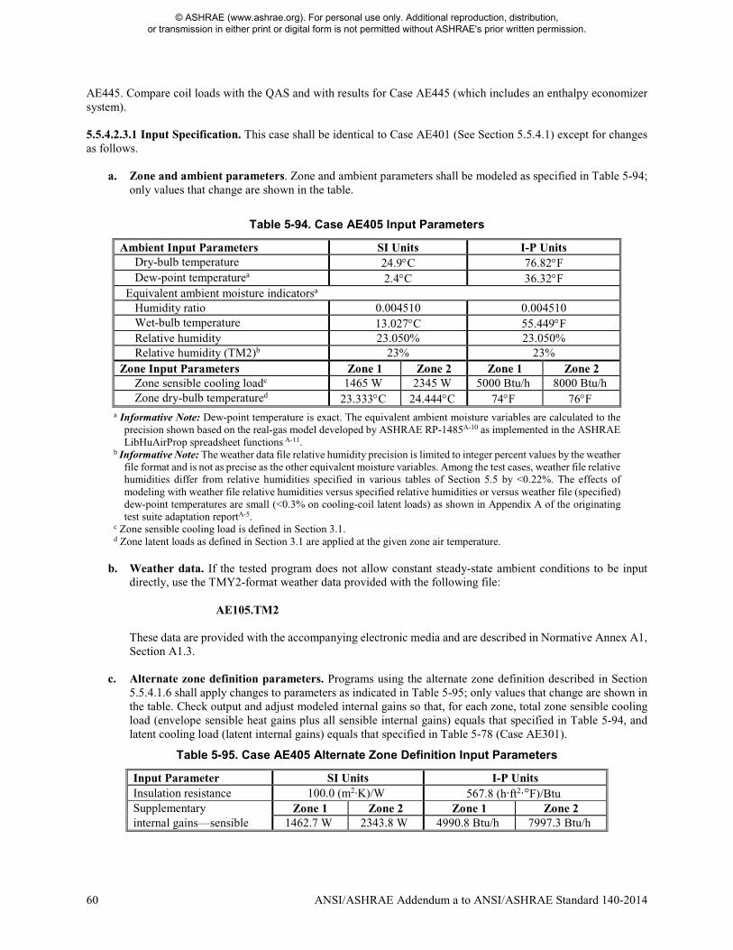
60 ANSI/ASHRAE Addendum a to ANSI/ASHRAE Standard 140-2014
AE445. Compare coil loads with the QAS and with results for Case AE445 (which includes an enthalpy economizer system). 5.5.4.2.3.1 Input Specification. This case shall be identical to Case AE401 (See Section 5.5.4.1) except for changes as follows.
a. Zone and ambient parameters. Zone and ambient parameters shall be modeled as specified in Table 5-94; only values that change are shown in the table.
Table 5-94. Case AE405 Input Parameters
Ambient Input Parameters SI Units I-P Units Dry-bulb temperature 24.9°C 76.82°F Dew-point temperaturea 2.4°C 36.32°F
Equivalent ambient moisture indicatorsa Humidity ratio 0.004510 0.004510 Wet-bulb temperature 13.027°C 55.449°F Relative humidity 23.050% 23.050% Relative humidity (TM2)b 23% 23%
Zone Input Parameters Zone 1 Zone 2 Zone 1 Zone 2 Zone sensible cooling loadc 1465 W 2345 W 5000 Btu/h 8000 Btu/h Zone dry-bulb temperatured 23.333°C 24.444°C 74°F 76°F
a Informative Note: Dew-point temperature is exact. The equivalent ambient moisture variables are calculated to the precision shown based on the real-gas model developed by ASHRAE RP-1485A-10 as implemented in the ASHRAE LibHuAirProp spreadsheet functions A-11.
b Informative Note: The weather data file relative humidity precision is limited to integer percent values by the weather file format and is not as precise as the other equivalent moisture variables. Among the test cases, weather file relative humidities differ from relative humidities specified in various tables of Section 5.5 by <0.22%. The effects of modeling with weather file relative humidities versus specified relative humidities or versus weather file (specified) dew-point temperatures are small (<0.3% on cooling-coil latent loads) as shown in Appendix A of the originating test suite adaptation reportA-5.
c Zone sensible cooling load is defined in Section 3.1. d Zone latent loads as defined in Section 3.1 are applied at the given zone air temperature.
b. Weather data. If the tested program does not allow constant steady-state ambient conditions to be input
directly, use the TMY2-format weather data provided with the following file: AE105.TM2
These data are provided with the accompanying electronic media and are described in Normative Annex A1, Section A1.3.
c. Alternate zone definition parameters. Programs using the alternate zone definition described in Section 5.5.4.1.6 shall apply changes to parameters as indicated in Table 5-95; only values that change are shown in the table. Check output and adjust modeled internal gains so that, for each zone, total zone sensible cooling load (envelope sensible heat gains plus all sensible internal gains) equals that specified in Table 5-94, and latent cooling load (latent internal gains) equals that specified in Table 5-78 (Case AE301).
Table 5-95. Case AE405 Alternate Zone Definition Input Parameters
Input Parameter SI Units I-P Units Insulation resistance 100.0 (m2·K)/W 567.8 (h·ft2·°F)/Btu Supplementary Zone 1 Zone 2 Zone 1 Zone 2 internal gains—sensible 1462.7 W 2343.8 W 4990.8 Btu/h 7997.3 Btu/h
© ASHRAE (www.ashrae.org). For personal use only. Additional reproduction, distribution, or transmission in either print or digital form is not permitted without ASHRAE's prior written permission.

ANSI/ASHRAE Addendum a to ANSI/ASHRAE Standard 140-2014 61
5.5.4.2.4 Case AE406: Low Cooling, Wet-Coil 1 Informative Note, Objective of the Test Case. Generate results for a variable-air-volume terminal reheat system without dry-bulb economizer, applying low sensible cooling load at warm, humid outdoor air conditions, to compare with results for the same system with dry-bulb economizer (Case AE426). Informative Note, Method of the Test Case. Use the Case AE401 model with modifications. Case AE406 applies an ambient dry-bulb temperature that ensures the economizer operates when it is specified in Case AE426. Humid ambient conditions and high sensible cooling load ensure a cold cooling coil with high latent loads. Check the cooling-coil leaving-air saturation to verify that the coil bypass factor is zero or near zero. Compare coil loads with the QAS and with results for Case AE426 (which includes a comparative dry-bulb economizer system). 5.5.4.2.4.1 Input Specification. This case shall be identical to Case AE401 (See Section 5.5.4.1) except for changes as follows.
a. Zone and ambient parameters. Zone and ambient parameters shall be modeled as specified in Table 5-96; only values that change are shown in the table.
Table 5-96. Case AE406 Input Parameters
Ambient Input Parameters SI Units I-P Units Dry-bulb temperature 23.0°C 73.40°F Dew-point temperaturea 20.9°C 69.62°F
Equivalent ambient moisture indicatorsa Humidity ratio 0.015625 0.015625 Wet-bulb temperature 21.523°C 70.741°F Relative humidity 87.968% 87.968% Relative humidity (TM2)b 88% 88%
Zone Input Parameters Zone 1 Zone 2 Zone 1 Zone 2 Zone sensible cooling loadc 1465 W 2345 W 5000 Btu/h 8000 Btu/h Zone dry-bulb temperatured 23.333°C 24.444°C 74°F 76°F
a Informative Note: Dew-point temperature is exact. The equivalent ambient moisture variables are calculated to the precision shown based on the real-gas model developed by ASHRAE RP-1485A-10 as implemented in the ASHRAE LibHuAirProp spreadsheet functions A-11.
b Informative Note: The weather data file relative humidity precision is limited to integer percent values by the weather file format and is not as precise as the other equivalent moisture variables. Among the test cases, weather file relative humidities differ from relative humidities specified in various tables of Section 5.5 by <0.22%. The effects of modeling with weather file relative humidities versus specified relative humidities or versus weather file (specified) dew-point temperatures are small (<0.3% on cooling-coil latent loads) as shown in Appendix A of the originating test suite adaptation reportA-5.
c Zone sensible cooling load is defined in Section 3.1. d Zone latent loads as defined in Section 3.1 are applied at the given zone air temperature.
b. Weather data. If the tested program does not allow constant steady-state ambient conditions to be input
directly, use the TMY2-format weather data provided with the following file: AE106.TM2
These data are provided with the accompanying electronic media and are described in Normative Annex A1, Section A1.3.
c. Alternate zone definition parameters. Programs using the alternate zone definition described in Section 5.5.4.1.6 shall apply changes to parameters as indicated in Table 5-97; only values that change are shown in the table. Check output and adjust modeled internal gains so that, for each zone, total zone sensible cooling
© ASHRAE (www.ashrae.org). For personal use only. Additional reproduction, distribution, or transmission in either print or digital form is not permitted without ASHRAE's prior written permission.
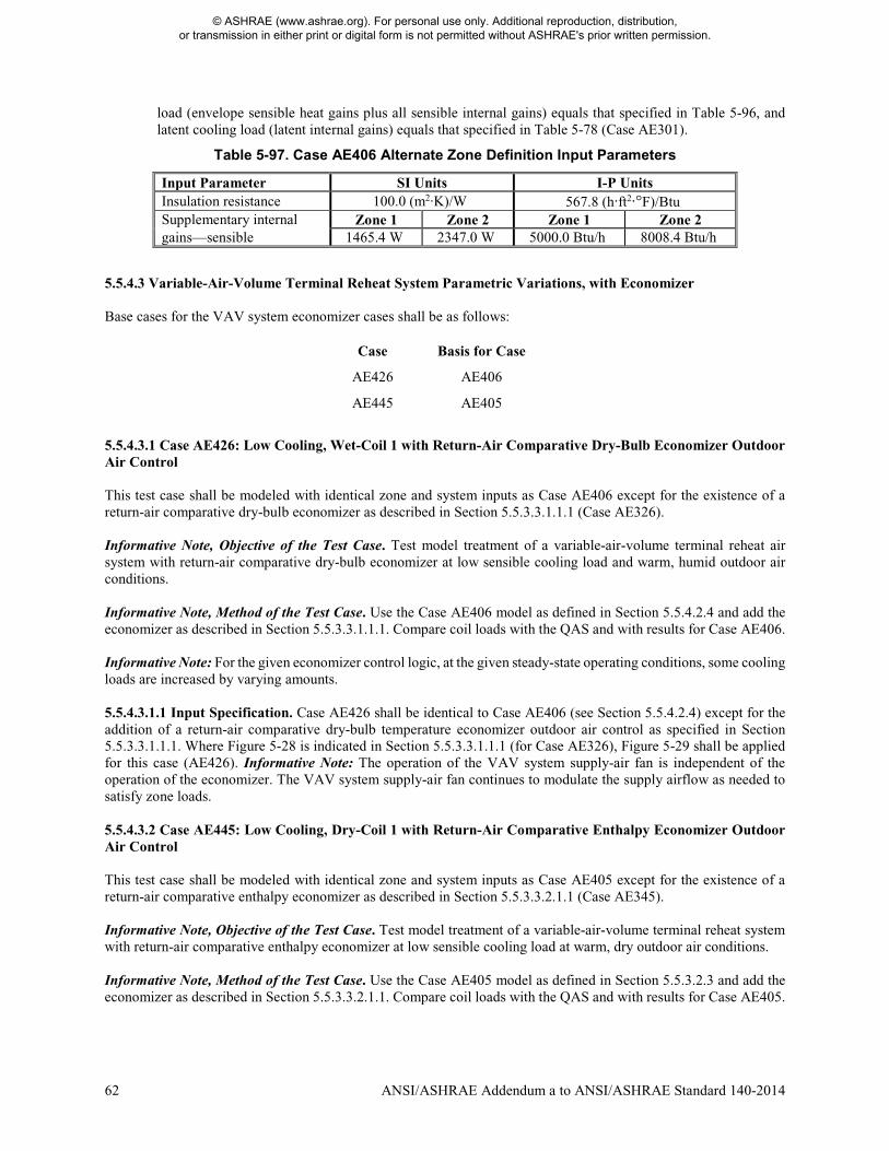
62 ANSI/ASHRAE Addendum a to ANSI/ASHRAE Standard 140-2014
load (envelope sensible heat gains plus all sensible internal gains) equals that specified in Table 5-96, and latent cooling load (latent internal gains) equals that specified in Table 5-78 (Case AE301).
Table 5-97. Case AE406 Alternate Zone Definition Input Parameters
Input Parameter SI Units I-P Units Insulation resistance 100.0 (m2·K)/W 567.8 (h·ft2·°F)/Btu Supplementary internal Zone 1 Zone 2 Zone 1 Zone 2 gains—sensible 1465.4 W 2347.0 W 5000.0 Btu/h 8008.4 Btu/h
5.5.4.3 Variable-Air-Volume Terminal Reheat System Parametric Variations, with Economizer Base cases for the VAV system economizer cases shall be as follows:
Case Basis for Case
AE426 AE406
AE445 AE405
5.5.4.3.1 Case AE426: Low Cooling, Wet-Coil 1 with Return-Air Comparative Dry-Bulb Economizer Outdoor Air Control This test case shall be modeled with identical zone and system inputs as Case AE406 except for the existence of a return-air comparative dry-bulb economizer as described in Section 5.5.3.3.1.1.1 (Case AE326). Informative Note, Objective of the Test Case. Test model treatment of a variable-air-volume terminal reheat air system with return-air comparative dry-bulb economizer at low sensible cooling load and warm, humid outdoor air conditions. Informative Note, Method of the Test Case. Use the Case AE406 model as defined in Section 5.5.4.2.4 and add the economizer as described in Section 5.5.3.3.1.1.1. Compare coil loads with the QAS and with results for Case AE406. Informative Note: For the given economizer control logic, at the given steady-state operating conditions, some cooling loads are increased by varying amounts. 5.5.4.3.1.1 Input Specification. Case AE426 shall be identical to Case AE406 (see Section 5.5.4.2.4) except for the addition of a return-air comparative dry-bulb temperature economizer outdoor air control as specified in Section 5.5.3.3.1.1.1. Where Figure 5-28 is indicated in Section 5.5.3.3.1.1.1 (for Case AE326), Figure 5-29 shall be applied for this case (AE426). Informative Note: The operation of the VAV system supply-air fan is independent of the operation of the economizer. The VAV system supply-air fan continues to modulate the supply airflow as needed to satisfy zone loads. 5.5.4.3.2 Case AE445: Low Cooling, Dry-Coil 1 with Return-Air Comparative Enthalpy Economizer Outdoor Air Control This test case shall be modeled with identical zone and system inputs as Case AE405 except for the existence of a return-air comparative enthalpy economizer as described in Section 5.5.3.3.2.1.1 (Case AE345). Informative Note, Objective of the Test Case. Test model treatment of a variable-air-volume terminal reheat system with return-air comparative enthalpy economizer at low sensible cooling load at warm, dry outdoor air conditions. Informative Note, Method of the Test Case. Use the Case AE405 model as defined in Section 5.5.3.2.3 and add the economizer as described in Section 5.5.3.3.2.1.1. Compare coil loads with the QAS and with results for Case AE405.
© ASHRAE (www.ashrae.org). For personal use only. Additional reproduction, distribution, or transmission in either print or digital form is not permitted without ASHRAE's prior written permission.
ANSI/ASHRAE Addendum a to ANSI/ASHRAE Standard 140-2014 63
Informative Note: For the given economizer control logic, at the given steady-state operating conditions, some cooling loads are increased by varying amounts. 5.5.4.3.2.1 Input Specification. Case AE445 shall be identical to Case AE405 (see Section 5.5.4.2.3) except for the addition of a return-air comparative enthalpy economizer outdoor air control as specified in Section 5.5.3.3.2.1.1. Where Figure 5-28 is indicated in Section 5.5.3.3.2.1.1 (for Case AE345), Figure 5-29 shall be applied for this case (AE445). Informative Note: The operation of the VAV system supply-air fan is independent of the operation of the economizer. The VAV system supply-air fan continues to modulate the supply airflow as needed to satisfy zone loads. Modify Section 6.1.1 as shown. 6.1 Reporting Results
6.1.1 Standard Output Reports. The standard output reports included on the accompanying electronic media shall be used. Instructions regarding these reports are included in Normative Annex A2. Information required for this report includes the following: c. Results for simulated cases using the following files on the accompanying electronic media:
6. Sec5-5out.XLSX for the air-side HVAC equipment performance analytical verification tests of Section 5.5. For the specific output quantities required in the results report for each case, refer to the appropriate subsections
of Sections 5.2, 5.3, and 5.4, and 5.5. Add new Section 6.5. 6.5 Output Requirements for Air-Side HVAC Equipment Performance Tests of Section 5.5 Outputs that are not direct program outputs shall be described in the output spreadsheet and modeler report using S140outNotes.txt (under report Block B, Alternative Modeling Methods) provided with the accompanying electronic media. Informative Note: Outputs that are not direct program outputs include spreadsheet and other externally coded postprocessor calculations and other manual calculations not performed directly by the program being tested. 6.5.1 Output Requirements for AE100 Series Cases Output results specified in this section shall be reported in the output spreadsheet (“Sec5-5out.XLSX”) provided with the accompanying electronic media, using the nomenclature and units specified here. The simulation shall be run until the final hour output agrees with the previous hour output, and the values specified in Sections 6.5.1.1, 6.5.1.2, and 6.5.1.3 shall be reported for the last hour of the simulation. 6.5.1.1 Zone Load Outputs—Last Hour of Simulation
a. Zone sensible heating load (QZHSensible [kWh/h]) b. Zone sensible cooling load (QZCSensible [kWh/h]) c. Zone latent load (QZLatent [kWh/h])
Zone loads are defined in Section 3.1. All zone loads shall be entered as positive values (≥0). When a zone sensible cooling load occurs, the zone sensible heating load shall be blank or zero; when a zone sensible heating load occurs, the zone sensible cooling load shall be blank or zero. 6.5.1.2 Heating and Cooling-Coil Outputs—Last Hour of Simulation
a. Heating-coil load (QH [kWh/h]) b. Cooling-coil sensible load (QCSensible [kWh/h]) c. Cooling-coil latent load (QCLatent [kWh/h]) d. Cooling-coil total load (QCTotal = QCSensible + QCLatent [kWh/h]) e. Cooling-coil leaving-air relative humidity (RHcco [%], as 0% ≤ RHcco ≤ 100%)
© ASHRAE (www.ashrae.org). For personal use only. Additional reproduction, distribution, or transmission in either print or digital form is not permitted without ASHRAE's prior written permission.
64 ANSI/ASHRAE Addendum a to ANSI/ASHRAE Standard 140-2014
Coil loads are defined in Section 3.1. All coil loads shall be entered as positive values (≥0). 6.5.1.3 Detailed Outputs—Last Hour of Simulation. Provide the dry-bulb temperature (°C), humidity ratio (g/gda), specific volume (L/kgda), enthalpy (J/gda), and mass flow rate (kgda/s) for the following locations as indicated by italicized labels in Figure 5-25:
a. Outdoor air inlet (oa) b. Mixed air (ma) c. Heating-coil outlet (hco) d. Cooling-coil outlet (cco) e. Zone supply air (sa) f. Zone air (z1) except mass flow rate g. Return air (ra)
6.5.2 Output Requirements for AE200 Series Cases Output results specified in this section shall be reported in the output spreadsheet (“Sec5-5out.XLSX”) provided with the accompanying electronic media, using the nomenclature and units specified here. The simulation shall be run until the final hour output agrees with thliste previous hour output, and the values specified in Sections 6.5.2.1, 6.5.2.2, and 6.5.2.3 shall be reported for the last hour of the simulation. 6.5.2.1 Zone Load Outputs—Last Hour of Simulation The requirements of Section 6.5.1.1 shall be applied. 6.5.2.2 Heating and Cooling-Coil Outputs—Last Hour of Simulation The requirements of Section 6.5.1.2 shall be applied. 6.5.2.3 Detailed Outputs—Last Hour of Simulation. Provide the dry-bulb temperature (°C), humidity ratio (g/gda), specific volume (L/kgda), enthalpy (J/gda), and mass flow rate (kgda/s) for the following locations as indicated by italicized labels in Figure 5-27:
a. Outdoor air inlet (oa) b. Mixed air (ma) c. Heating-coil outlet (hco) d. Cooling-coil outlet (cco) e. Zone supply air (sa) f. Zone air (z1), except mass flow rate g. Return fan inlet (rfi) h. Return fan outlet (rfo)
6.5.3 Output Requirements for AE300 Series Cases Output results specified in this section shall be reported in the output spreadsheet (“Sec5-5out.XLSX”) provided with the accompanying electronic media, using the nomenclature and units specified here. The simulation shall be run until the final hour output agrees with the previous hour output, and the values specified in Sections 6.5.3.1, 6.5.3.2, and 6.5.3.3 shall be reported for the last hour of the simulation. 6.5.3.1 Zone Load Outputs—Last Hour of Simulation
a. Zone 1 sensible heating load (QZH1Sensible [kWh/h]) b. Zone 1 sensible cooling load (QZC1Sensible [kWh/h]) c. Zone 1 latent load (QZ1Latent [kWh/h]) d. Zone 2 sensible heating load (QZH2Sensible [kWh/h])
© ASHRAE (www.ashrae.org). For personal use only. Additional reproduction, distribution, or transmission in either print or digital form is not permitted without ASHRAE's prior written permission.

ANSI/ASHRAE Addendum a to ANSI/ASHRAE Standard 140-2014 65
e. Zone 2 sensible cooling load (QZC2Sensible [kWh/h]) f. Zone 2 latent load (QZ2Latent [kWh/h])
Zone loads are defined in Section 3.1. All zone loads shall be entered as positive values (≥0). When a zone sensible cooling load occurs, the zone sensible heating load shall be blank or zero; when a zone sensible heating load occurs, the zone sensible cooling load shall be blank or zero. 6.5.3.2 Heating and Cooling-Coil Outputs—Last Hour of Simulation
a. Preheat-coil load (QHPreheat [kWh/h]) b. Cooling-coil sensible load (QCSensible [kWh/h]) c. Cooling-coil latent load (QCLatent [kWh/h]) d. Cooling-coil total load (QCTotal = QCSensible + QCLatent [kWh/h]) e. Cooling-coil leaving-air relative humidity (RHcco [%], as 0% ≤ RHcco ≤ 100%) f. Zone 1 reheat-coil load (QH1Reheat [kWh/h]) g. Zone 2 reheat-coil load (QH2Reheat [kWh/h])
Coil loads are defined in Section 3.1. All coil loads shall be entered as positive values (≥0). 6.5.3.3 Detailed Outputs—Last Hour of Simulation. Provide the dry-bulb temperature (°C), humidity ratio (g/gda), specific volume (L/kgda), enthalpy (J/gda), and mass flow rate (kgda/s) for the following locations as indicated by italicized labels in Figure 5-28:
a. Outdoor air inlet (oa) b. Mixed air (ma) c. Preheat-coil outlet (pco) d. Cooling-coil outlet (cco) e. System supply air (sa) f. Zone 1 supply air from reheat-coil outlet (z1s) g. Zone 2 supply air from reheat-coil outlet (z2s) h. Zone 1 (z1) except mass flow rate i. Zone 2 (z2) except mass flow rate j. Return fan inlet (rfi) k. Return fan outlet (rfo)
6.5.4 Output Requirements for AE400 Series Cases Output results specified in this section shall be reported in the output spreadsheet (“Sec5-5out.XLSX”) provided with the accompanying electronic media, using the nomenclature and units specified here. The simulation shall be run until the final hour output agrees with the previous hour output, and the values specified in Sections 6.5.4.1, 6.5.4.2, and 6.5.4.3 shall be reported for the last hour of the simulation. 6.5.4.1 Zone Load Outputs—Last Hour of Simulation The requirements of Section 6.5.3.1 shall be applied.
© ASHRAE (www.ashrae.org). For personal use only. Additional reproduction, distribution, or transmission in either print or digital form is not permitted without ASHRAE's prior written permission.
66 ANSI/ASHRAE Addendum a to ANSI/ASHRAE Standard 140-2014
6.5.4.2 Heating and Cooling-Coil Outputs—Last Hour of Simulation The requirements of Section 6.5.3.2 shall be applied. 6.5.4.3 Detailed Outputs—Last Hour of Simulation. Provide the dry-bulb temperature (°C), humidity ratio (g/gda), specific volume (L/kgda), enthalpy (J/gda), and mass flow rate (kgda/s) for the following locations as indicated by italicized labels in Figure 5-29:
a. Outdoor air inlet (oa) b. Mixed air (ma) c. Preheat-coil outlet (pco) d. Cooling-coil outlet (cco) e. System supply air (sa) f. Zone 1 supply air from VAV terminal reheat-coil outlet (z1s) g. Zone 2 supply air from VAV terminal reheat-coil outlet (z2s) h. Zone 1 (z1) except mass flow rate i. Zone 2 (z2) except mass flow rate j. Return fan inlet (rfi) k. Return fan outlet (rfo)
© ASHRAE (www.ashrae.org). For personal use only. Additional reproduction, distribution, or transmission in either print or digital form is not permitted without ASHRAE's prior written permission.
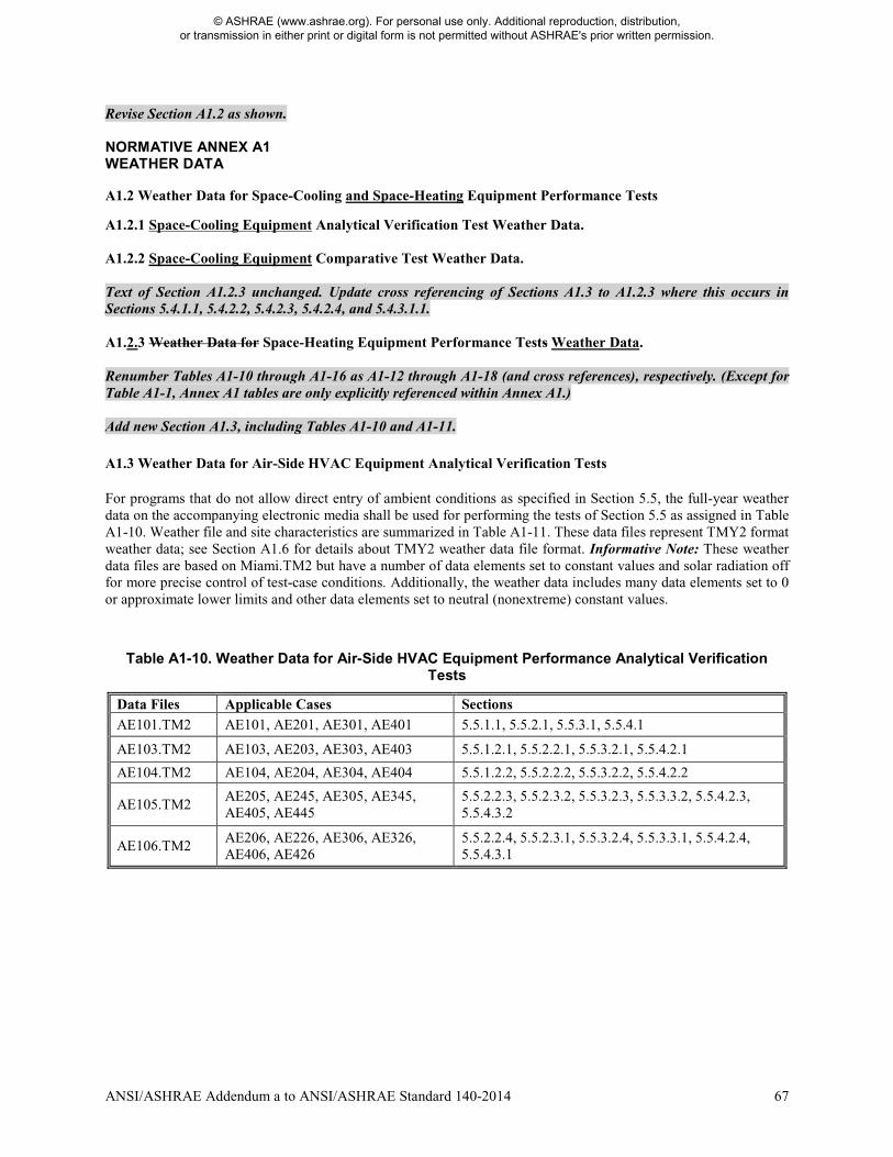
ANSI/ASHRAE Addendum a to ANSI/ASHRAE Standard 140-2014 67
Revise Section A1.2 as shown. NORMATIVE ANNEX A1 WEATHER DATA A1.2 Weather Data for Space-Cooling and Space-Heating Equipment Performance Tests A1.2.1 Space-Cooling Equipment Analytical Verification Test Weather Data. A1.2.2 Space-Cooling Equipment Comparative Test Weather Data. Text of Section A1.2.3 unchanged. Update cross referencing of Sections A1.3 to A1.2.3 where this occurs in Sections 5.4.1.1, 5.4.2.2, 5.4.2.3, 5.4.2.4, and 5.4.3.1.1. A1.2.3 Weather Data for Space-Heating Equipment Performance Tests Weather Data. Renumber Tables A1-10 through A1-16 as A1-12 through A1-18 (and cross references), respectively. (Except for Table A1-1, Annex A1 tables are only explicitly referenced within Annex A1.) Add new Section A1.3, including Tables A1-10 and A1-11. A1.3 Weather Data for Air-Side HVAC Equipment Analytical Verification Tests For programs that do not allow direct entry of ambient conditions as specified in Section 5.5, the full-year weather data on the accompanying electronic media shall be used for performing the tests of Section 5.5 as assigned in Table A1-10. Weather file and site characteristics are summarized in Table A1-11. These data files represent TMY2 format weather data; see Section A1.6 for details about TMY2 weather data file format. Informative Note: These weather data files are based on Miami.TM2 but have a number of data elements set to constant values and solar radiation off for more precise control of test-case conditions. Additionally, the weather data includes many data elements set to 0 or approximate lower limits and other data elements set to neutral (nonextreme) constant values.
Table A1-10. Weather Data for Air-Side HVAC Equipment Performance Analytical Verification Tests
Data Files Applicable Cases Sections AE101.TM2 AE101, AE201, AE301, AE401 5.5.1.1, 5.5.2.1, 5.5.3.1, 5.5.4.1
AE103.TM2 AE103, AE203, AE303, AE403 5.5.1.2.1, 5.5.2.2.1, 5.5.3.2.1, 5.5.4.2.1
AE104.TM2 AE104, AE204, AE304, AE404 5.5.1.2.2, 5.5.2.2.2, 5.5.3.2.2, 5.5.4.2.2
AE105.TM2 AE205, AE245, AE305, AE345, AE405, AE445
5.5.2.2.3, 5.5.2.3.2, 5.5.3.2.3, 5.5.3.3.2, 5.5.4.2.3, 5.5.4.3.2
AE106.TM2 AE206, AE226, AE306, AE326, AE406, AE426
5.5.2.2.4, 5.5.2.3.1, 5.5.3.2.4, 5.5.3.3.1, 5.5.4.2.4, 5.5.4.3.1
© ASHRAE (www.ashrae.org). For personal use only. Additional reproduction, distribution, or transmission in either print or digital form is not permitted without ASHRAE's prior written permission.
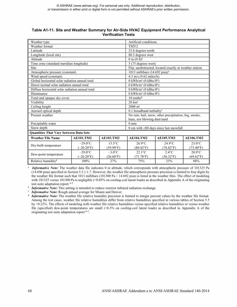
68 ANSI/ASHRAE Addendum a to ANSI/ASHRAE Standard 140-2014
Table A1-11. Site and Weather Summary for Air-Side HVAC Equipment Performance Analytical Verification Tests
Weather type Artificial conditions Weather format TMY2 Latitude 25.8 degrees north Longitude (local site) 80.3 degrees west Altitude 0 m (0 ft)a Time zone (standard meridian longitude) 5 (75 degrees west) Site Flat, unobstructed, located exactly at weather station Atmospheric pressure (constant) 1013 millibars (14.692 psia)a Wind speed (constant) 4.3 m/s (9.62 miles/h) Global horizontal solar radiation annual total 0 kWh/m² (0 kBtu/ft²) Direct normal solar radiation annual total 0 kWh/m² (0 kBtu/ft²) Diffuse horizontal solar radiation annual total 0 kWh/m² (0 kBtu/ft²) Illuminance 0 kWh/m² (0 kBtu/ft²) Total and opaque sky cover 10 tenthsb Visibility 20 kmc Ceiling height 2000 mc Aerosol optical depth 0.1 broadband turbidityc Present weather No rain, hail, snow, other precipitation, fog, smoke,
haze, nor blowing dust/sand Precipitable water 0 mm Snow depth 0 cm with ≥88 days since last snowfall
Quantities That Vary between Data Sets
Weather File Name AE101.TM2 AE103.TM2 AE104.TM2 AE105.TM2 AE106.TM2
Dry-bulb temperature –29.0°C
(–20.20°F) 15.5°C
(59.90°F) 26.9°C
(80.42°F) 24.9°C
(76.82°F) 23.0°C
(73.40°F)
Dew-point temperature –29.0°C
(–20.20°F) –3.0°C
(26.60°F) 22.1°C
(71.78°F) 2.4°C
(36.32°F) 20.9°C
(69.62°F) Relative humidityd 100% 27% 75% 23% 88%
a Informative Note: The weather data file indicates 0 m altitude, which corresponds with atmospheric pressure of 101325 Pa (14.696 psia) specified in Section 5.5.1.1.7. However, the weather file atmospheric pressure precision is limited to four digits by the weather file format such that 1013 millibars (101300 Pa = 14.692 psia) is listed in the weather files. The effect of modeling with 101325 versus 101300 Pa is negligible (<0.05% on cooling-coil latent loads) as described in Appendix A of the originating test suite adaptation report.A-5
b Informative Note: This setting is intended to reduce exterior infrared radiation exchange. c Informative Note: Rough annual average for Miami and Denver. d Informative Note: The weather file relative humidity precision is limited to integer percent values by the weather file format.
Among the test cases, weather file relative humidities differ from relative humidities specified in various tables of Section 5.5 by <0.22%. The effects of modeling with weather file relative humidities versus specified relative humidities or versus weather file (specified) dew-point temperatures are small (<0.3% on cooling-coil latent loads) as described in Appendix A of the originating test suite adaptation report A-5.
© ASHRAE (www.ashrae.org). For personal use only. Additional reproduction, distribution, or transmission in either print or digital form is not permitted without ASHRAE's prior written permission.
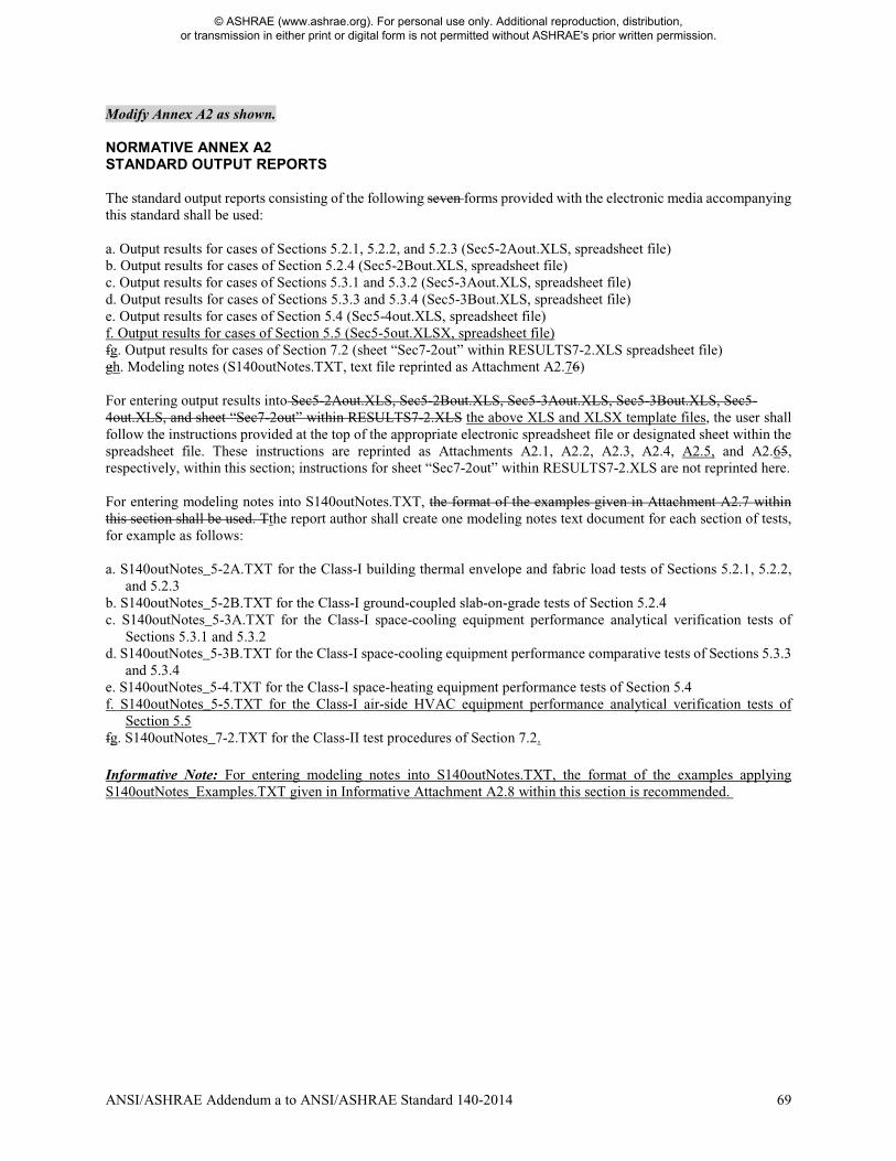
ANSI/ASHRAE Addendum a to ANSI/ASHRAE Standard 140-2014 69
Modify Annex A2 as shown. NORMATIVE ANNEX A2 STANDARD OUTPUT REPORTS The standard output reports consisting of the following seven forms provided with the electronic media accompanying this standard shall be used: a. Output results for cases of Sections 5.2.1, 5.2.2, and 5.2.3 (Sec5-2Aout.XLS, spreadsheet file) b. Output results for cases of Section 5.2.4 (Sec5-2Bout.XLS, spreadsheet file) c. Output results for cases of Sections 5.3.1 and 5.3.2 (Sec5-3Aout.XLS, spreadsheet file) d. Output results for cases of Sections 5.3.3 and 5.3.4 (Sec5-3Bout.XLS, spreadsheet file) e. Output results for cases of Section 5.4 (Sec5-4out.XLS, spreadsheet file) f. Output results for cases of Section 5.5 (Sec5-5out.XLSX, spreadsheet file) fg. Output results for cases of Section 7.2 (sheet “Sec7-2out” within RESULTS7-2.XLS spreadsheet file) gh. Modeling notes (S140outNotes.TXT, text file reprinted as Attachment A2.76) For entering output results into Sec5-2Aout.XLS, Sec5-2Bout.XLS, Sec5-3Aout.XLS, Sec5-3Bout.XLS, Sec5- 4out.XLS, and sheet “Sec7-2out” within RESULTS7-2.XLS the above XLS and XLSX template files, the user shall follow the instructions provided at the top of the appropriate electronic spreadsheet file or designated sheet within the spreadsheet file. These instructions are reprinted as Attachments A2.1, A2.2, A2.3, A2.4, A2.5, and A2.65, respectively, within this section; instructions for sheet “Sec7-2out” within RESULTS7-2.XLS are not reprinted here. For entering modeling notes into S140outNotes.TXT, the format of the examples given in Attachment A2.7 within this section shall be used. Tthe report author shall create one modeling notes text document for each section of tests, for example as follows: a. S140outNotes_5-2A.TXT for the Class-I building thermal envelope and fabric load tests of Sections 5.2.1, 5.2.2,
and 5.2.3 b. S140outNotes_5-2B.TXT for the Class-I ground-coupled slab-on-grade tests of Section 5.2.4 c. S140outNotes_5-3A.TXT for the Class-I space-cooling equipment performance analytical verification tests of
Sections 5.3.1 and 5.3.2 d. S140outNotes_5-3B.TXT for the Class-I space-cooling equipment performance comparative tests of Sections 5.3.3
and 5.3.4 e. S140outNotes_5-4.TXT for the Class-I space-heating equipment performance tests of Section 5.4 f. S140outNotes_5-5.TXT for the Class-I air-side HVAC equipment performance analytical verification tests of
Section 5.5 fg. S140outNotes_7-2.TXT for the Class-II test procedures of Section 7.2. Informative Note: For entering modeling notes into S140outNotes.TXT, the format of the examples applying S140outNotes_Examples.TXT given in Informative Attachment A2.8 within this section is recommended.
© ASHRAE (www.ashrae.org). For personal use only. Additional reproduction, distribution, or transmission in either print or digital form is not permitted without ASHRAE's prior written permission.
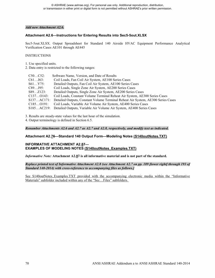
70 ANSI/ASHRAE Addendum a to ANSI/ASHRAE Standard 140-2014
Add new Attachment A2.6. Attachment A2.6—Instructions for Entering Results into Sec5-5out.XLSX Sec5-5out.XLSX. Output Spreadsheet for Standard 140 Airside HVAC Equipment Performance Analytical Verification Cases AE101 through AE445 INSTRUCTIONS 1. Use specified units. 2. Data entry is restricted to the following ranges:
C50…C52: Software Name, Version, and Date of Results C61…J63: Coil Loads, Fan Coil Air System, AE100 Series Cases S61…Y75: Detailed Outputs, Fan Coil Air System, AE100 Series Cases C89…J95: Coil Loads, Single Zone Air System, AE200 Series Cases S89…Z123: Detailed Outputs, Single Zone Air System, AE200 Series Cases C137…O143: Coil Loads, Constant Volume Terminal Reheat Air System, AE300 Series Cases S137…AC171: Detailed Outputs, Constant Volume Terminal Reheat Air System, AE300 Series Cases C185…O191: Coil Loads, Variable Air Volume Air System, AE400 Series Cases S185…AC219: Detailed Outputs, Variable Air Volume Air System, AE400 Series Cases
3. Results are steady-state values for the last hour of the simulation. 4. Output terminology is defined in Section 6.5. Renumber Attachments A2.6 and A2.7 as A2.7 and A2.8, respectively, and modify text as indicated. Attachment A2.76—Standard 140 Output Form—Modeling Notes (S140outNotes.TXT) INFORMATIVE ATTACHMENT A2.87— EXAMPLES OF MODELING NOTES (S140outNotes_Examples.TXT) Informative Note: Attachment A2.87 is all informative material and is not part of the standard. Replace printed text of Informative Attachment A2.8 (see Attachment A2.7 on pp. 189 [lower right] through 193 of Standard 140-2014) with cross-reference to accompanying files as follows.] See S140outNotes_Examples.TXT provided with the accompanying electronic media within the “Informative Materials” subfolder included within any of the “Sec…Files” subfolders.
© ASHRAE (www.ashrae.org). For personal use only. Additional reproduction, distribution, or transmission in either print or digital form is not permitted without ASHRAE's prior written permission.
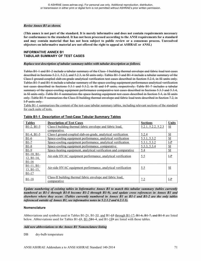
ANSI/ASHRAE Addendum a to ANSI/ASHRAE Standard 140-2014 71
Revise Annex B1 as shown. (This annex is not part of the standard. It is merely informative and does not contain requirements necessary for conformance to the standard. It has not been processed according to the ANSI requirements for a standard and may contain material that has not been subject to public review or a consensus process. Unresolved objectors on informative material are not offered the right to appeal at ASHRAE or ANSI.) INFORMATIVE ANNEX B1 TABULAR SUMMARY OF TEST CASES Replace text description of tabular summary tables with tabular description as follows. Tables B1-1 and B1-2 include a tabular summary of the Class- I building thermal envelope and fabric load test cases described in Sections 5.2.1, 5.2.2, and 5.2.3, in SI units only. Tables B1-3 and B1-4 include a tabular summary of the Class-I ground-coupled slab-on-grade analytical verification test cases described in Section 5.2.4, in SI units only. Tables B1-5 and B1-6 include a tabular summary of the space-cooling equipment performance analytical verification test cases described in Sections 5.3.1 and 5.3.2, in SI and I-P units, respectively. Table B1-7 includes a tabular summary of the space-cooling equipment performance comparative test cases described in Sections 5.3.3 and 5.3.4, in SI units only. Table B1-8 summarizes the space-heating equipment test cases described in Section 5.4, in SI units only. Table B1-9 summarizes the Class-II building thermal envelope and fabric load tests described in Section 7.2, in I-P units only. Table B1-1 summarizes the content of the test-case tabular summary tables, including relevant sections of the standard for each suite of tests. Table B1-1 Description of Test-Case Tabular Summary Tables
Tables Description of Test Cases Sections Units B1-2, B1-3 Class-I building thermal fabric envelope and fabric load,
comparative 5.2.1, 5.2.2, 5.2.3 SI
B1-4, B1-5 Class-I ground-coupled slab-on-grade, analytical verification 5.2.4 SI B1-6 Space-cooling equipment performance, analytical verification 5.3.1, 5.3.2 SI B1-7 Space-cooling equipment performance, analytical verification 5.3.1, 5.3.2 I-P B1-8 Space-cooling equipment performance, comparative 5.3.3, 5.3.4 SI B1-9 Space-heating equipment, analytical verification and comparative 5.4 SI B1-10, B1-12, B1-14, B1-16
Air-side HVAC equipment performance, analytical verification 5.5 I-P
B1-11, B1-13, B1-15, B1-17
Air-side HVAC equipment performance, analytical verification 5.5 SI
B1-18 Class-II building thermal fabric envelope and fabric load, comparative 7.2 I-P
Update numbering of existing tables in Informative Annex B1 to match this tabular summary (tables currently numbered as B1-1 through B1-8 become B1-2 through B1-9), and update cross references in Annex B1 and elsewhere where they occur. (Tables currently numbered in Annex B1 as B1-1 and B1-2 are the only tables referenced outside of Annex B1, see informative notes in 5.2.1.2 and 6.2.1.1). Nomenclature Abbreviations and symbols used in Tables B1-21, B1-32, and B1-65 through B1-17, B1-6, B1-7, and B1-8 are listed below. Abbreviations used for Tables B1-43, B1-5B1-4, and B1-189 are listed with those tables. Add new abbreviations to the Annex B1 Nomenclature listing DB dry-bulb temperature
© ASHRAE (www.ashrae.org). For personal use only. Additional reproduction, distribution, or transmission in either print or digital form is not permitted without ASHRAE's prior written permission.
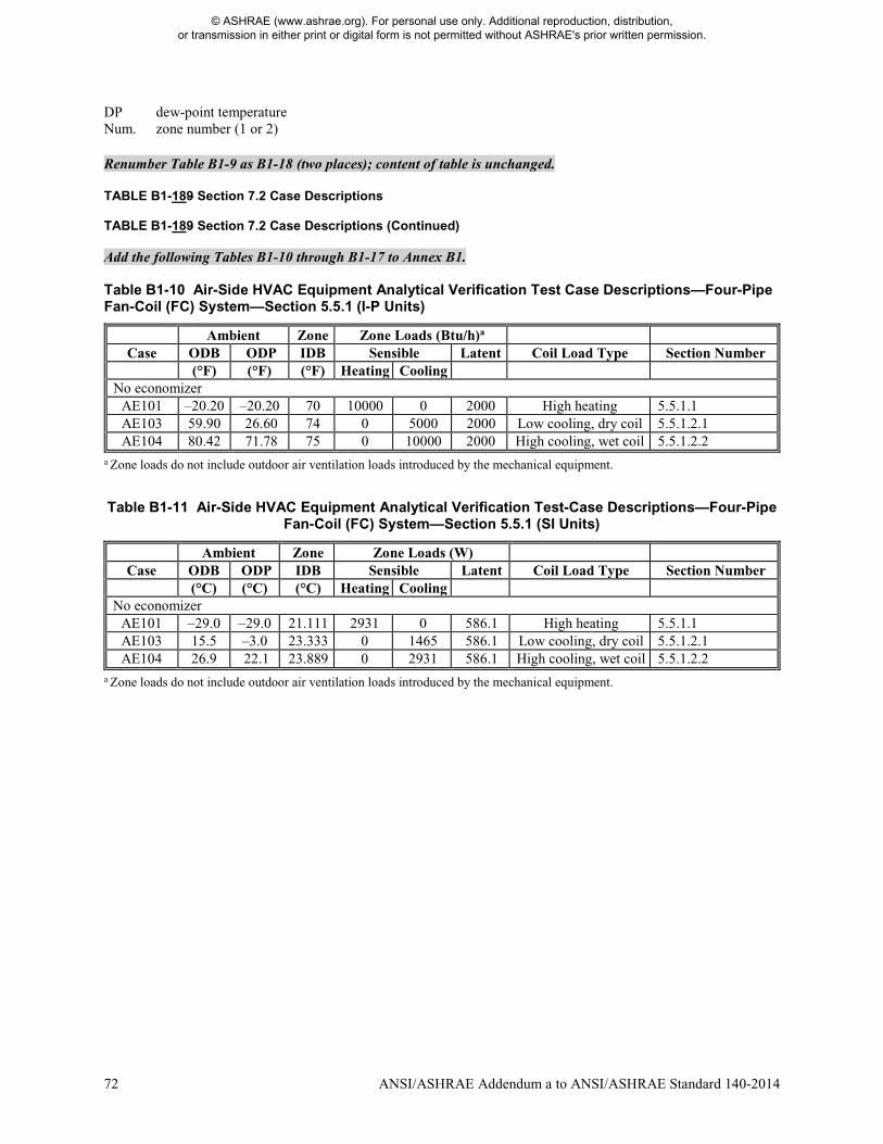
72 ANSI/ASHRAE Addendum a to ANSI/ASHRAE Standard 140-2014
DP dew-point temperature Num. zone number (1 or 2) Renumber Table B1-9 as B1-18 (two places); content of table is unchanged. TABLE B1-189 Section 7.2 Case Descriptions TABLE B1-189 Section 7.2 Case Descriptions (Continued) Add the following Tables B1-10 through B1-17 to Annex B1. Table B1-10 Air-Side HVAC Equipment Analytical Verification Test Case Descriptions—Four-Pipe Fan-Coil (FC) System—Section 5.5.1 (I-P Units)
Ambient Zone Zone Loads (Btu/h)a Case ODB ODP IDB Sensible Latent Coil Load Type Section Number
(°F) (°F) (°F) Heating Cooling No economizer
AE101 –20.20 –20.20 70 10000 0 2000 High heating 5.5.1.1 AE103 59.90 26.60 74 0 5000 2000 Low cooling, dry coil 5.5.1.2.1 AE104 80.42 71.78 75 0 10000 2000 High cooling, wet coil 5.5.1.2.2
a Zone loads do not include outdoor air ventilation loads introduced by the mechanical equipment.
Table B1-11 Air-Side HVAC Equipment Analytical Verification Test-Case Descriptions—Four-Pipe Fan-Coil (FC) System—Section 5.5.1 (SI Units)
Ambient Zone Zone Loads (W) Case ODB ODP IDB Sensible Latent Coil Load Type Section Number
(°C) (°C) (°C) Heating Cooling No economizer
AE101 –29.0 –29.0 21.111 2931 0 586.1 High heating 5.5.1.1 AE103 15.5 –3.0 23.333 0 1465 586.1 Low cooling, dry coil 5.5.1.2.1 AE104 26.9 22.1 23.889 0 2931 586.1 High cooling, wet coil 5.5.1.2.2
a Zone loads do not include outdoor air ventilation loads introduced by the mechanical equipment.
© ASHRAE (www.ashrae.org). For personal use only. Additional reproduction, distribution, or transmission in either print or digital form is not permitted without ASHRAE's prior written permission.
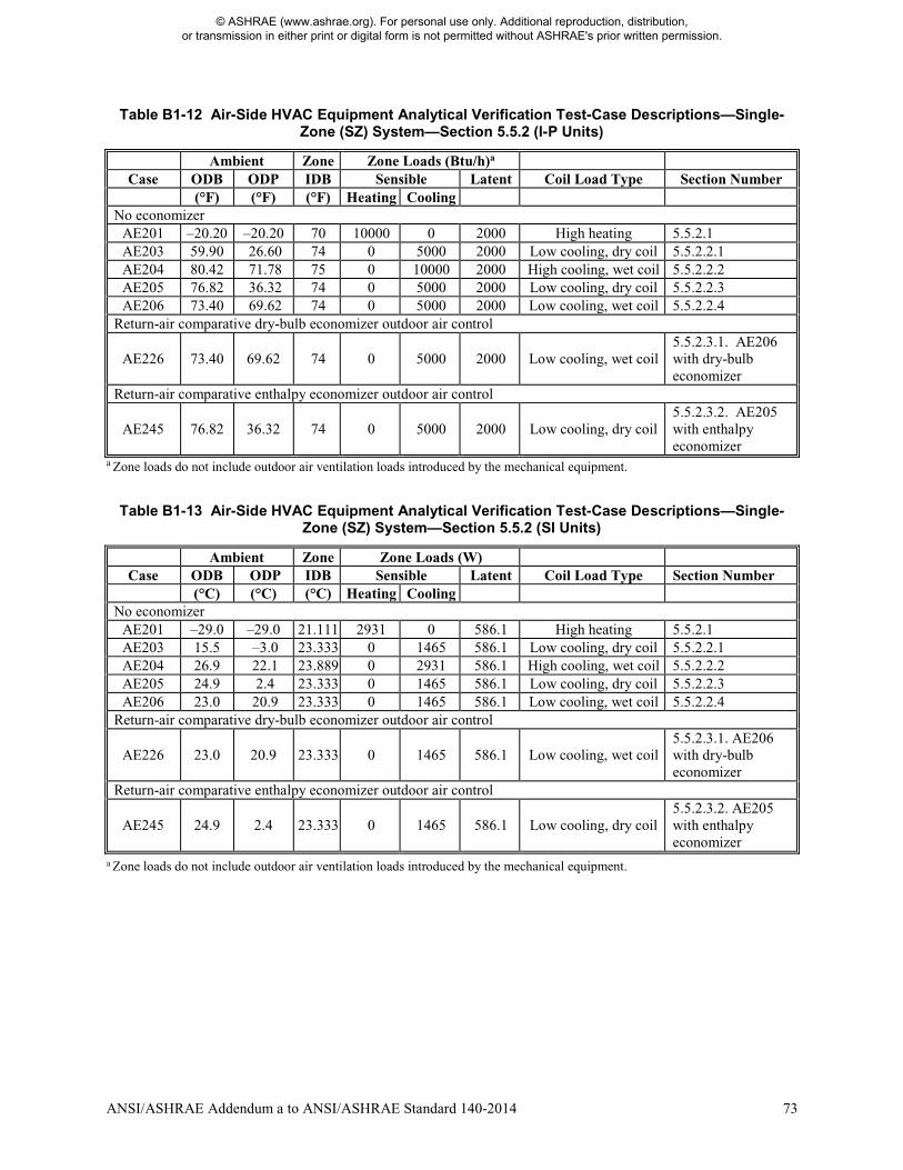
ANSI/ASHRAE Addendum a to ANSI/ASHRAE Standard 140-2014 73
Table B1-12 Air-Side HVAC Equipment Analytical Verification Test-Case Descriptions—Single-Zone (SZ) System—Section 5.5.2 (I-P Units)
Ambient Zone Zone Loads (Btu/h)a Case ODB ODP IDB Sensible Latent Coil Load Type Section Number
(°F) (°F) (°F) Heating Cooling No economizer
AE201 –20.20 –20.20 70 10000 0 2000 High heating 5.5.2.1 AE203 59.90 26.60 74 0 5000 2000 Low cooling, dry coil 5.5.2.2.1 AE204 80.42 71.78 75 0 10000 2000 High cooling, wet coil 5.5.2.2.2 AE205 76.82 36.32 74 0 5000 2000 Low cooling, dry coil 5.5.2.2.3 AE206 73.40 69.62 74 0 5000 2000 Low cooling, wet coil 5.5.2.2.4
Return-air comparative dry-bulb economizer outdoor air control
AE226 73.40 69.62 74 0 5000 2000 Low cooling, wet coil 5.5.2.3.1. AE206 with dry-bulb economizer
Return-air comparative enthalpy economizer outdoor air control
AE245 76.82 36.32 74 0 5000 2000 Low cooling, dry coil 5.5.2.3.2. AE205 with enthalpy economizer
a Zone loads do not include outdoor air ventilation loads introduced by the mechanical equipment.
Table B1-13 Air-Side HVAC Equipment Analytical Verification Test-Case Descriptions—Single-Zone (SZ) System—Section 5.5.2 (SI Units)
Ambient Zone Zone Loads (W) Case ODB ODP IDB Sensible Latent Coil Load Type Section Number
(°C) (°C) (°C) Heating Cooling No economizer
AE201 –29.0 –29.0 21.111 2931 0 586.1 High heating 5.5.2.1 AE203 15.5 –3.0 23.333 0 1465 586.1 Low cooling, dry coil 5.5.2.2.1 AE204 26.9 22.1 23.889 0 2931 586.1 High cooling, wet coil 5.5.2.2.2 AE205 24.9 2.4 23.333 0 1465 586.1 Low cooling, dry coil 5.5.2.2.3 AE206 23.0 20.9 23.333 0 1465 586.1 Low cooling, wet coil 5.5.2.2.4
Return-air comparative dry-bulb economizer outdoor air control
AE226 23.0 20.9 23.333 0 1465 586.1 Low cooling, wet coil 5.5.2.3.1. AE206 with dry-bulb economizer
Return-air comparative enthalpy economizer outdoor air control
AE245 24.9 2.4 23.333 0 1465 586.1 Low cooling, dry coil 5.5.2.3.2. AE205 with enthalpy economizer
a Zone loads do not include outdoor air ventilation loads introduced by the mechanical equipment.
© ASHRAE (www.ashrae.org). For personal use only. Additional reproduction, distribution, or transmission in either print or digital form is not permitted without ASHRAE's prior written permission.
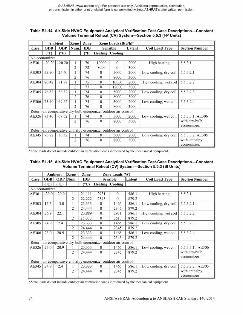
74 ANSI/ASHRAE Addendum a to ANSI/ASHRAE Standard 140-2014
Table B1-14 Air-Side HVAC Equipment Analytical Verification Test-Case Descriptions—Constant Volume Terminal Reheat (CV) System—Section 5.5.3 (I-P Units)
Ambient Zone Zone Zone Loads (Btu/h)a Case ODB ODP Num. IDB Sensible Latent Coil Load Type Section Number
(°F) (°F) (°F) Heating Cooling No economizer AE301 –20.20 –20.20 1 70 10000 0 2000 High heating 5.5.3.1
2 72 8000 0 3000 AE303 59.90 26.60 1 74 0 5000 2000 Low cooling, dry coil 5.5.3.2.1
2 76 0 8000 3000 AE304 80.42 71.78 1 75 0 10000 2000 High cooling, wet coil 5.5.3.2.2
2 77 0 12000 3000 AE305 76.82 36.32 1 74 0 5000 2000 Low cooling, dry coil 5.5.3.2.3
2 76 0 8000 3000 AE306 73.40 69.62 1 74 0 5000 2000 Low cooling, wet coil 5.5.3.2.4
2 76 0 8000 3000 Return-air comparative dry-bulb economizer outdoor air control AE326 73.40 69.62 1 74 0 5000 2000 Low cooling, wet coil 5.5.3.3.1. AE306
with dry-bulb economizer.
2 76 0 8000 3000
Return-air comparative enthalpy economizer outdoor air control AE345 76.82 36.32 1 74 0 5000 2000 Low cooling, dry coil 5.5.3.3.2. AE305
with enthalpy economizer.
2 76 0 8000 3000
a Zone loads do not include outdoor air ventilation loads introduced by the mechanical equipment.
Table B1-15 Air-Side HVAC Equipment Analytical Verification Test-Case Descriptions—Constant Volume Terminal Reheat (CV) System—Section 5.5.3 (SI Units)
Ambient Zone Zone Zone Loads (W) Case ODB ODP Num. IDB Sensible Latent Coil Load Type Section Number
(°C) (°C) (°C) Heating Cooling No economizer AE301 –29.0 –29.0 1 21.111 2931 0 586.1 High heating 5.5.3.1
2 22.222 2345 0 879.2 AE303 15.5 –3.0 1 23.333 0 1465 586.1 Low cooling, dry coil 5.5.3.2.1
2 24.444 0 2345 879.2 AE304 26.9 22.1 1 23.889 0 2931 586.1 High cooling, wet coil 5.5.3.2.2
2 25.000 0 3517 879.2 AE305 24.9 2.4 1 23.333 0 1465 586.1 Low cooling, dry coil 5.5.3.2.3
2 24.444 0 2345 879.2 AE306 23.0 20.9 1 23.333 0 1465 586.1 Low cooling, wet coil 5.5.3.2.4
2 24.444 0 2345 879.2 Return-air comparative dry-bulb economizer outdoor air control AE326 23.0 20.9 1 23.333 0 1465 586.1 Low cooling, wet coil 5.5.3.3.1. AE306
with dry-bulb economizer
2 24.444 0 2345 879.2
Return-air comparative enthalpy economizer outdoor air control AE345 24.9 2.4 1 23.333 0 1465 586.1 Low cooling, dry coil 5.5.3.3.2. AE305
with enthalpy economizer
2 24.444 0 2345 879.2
a Zone loads do not include outdoor air ventilation loads introduced by the mechanical equipment.
© ASHRAE (www.ashrae.org). For personal use only. Additional reproduction, distribution, or transmission in either print or digital form is not permitted without ASHRAE's prior written permission.
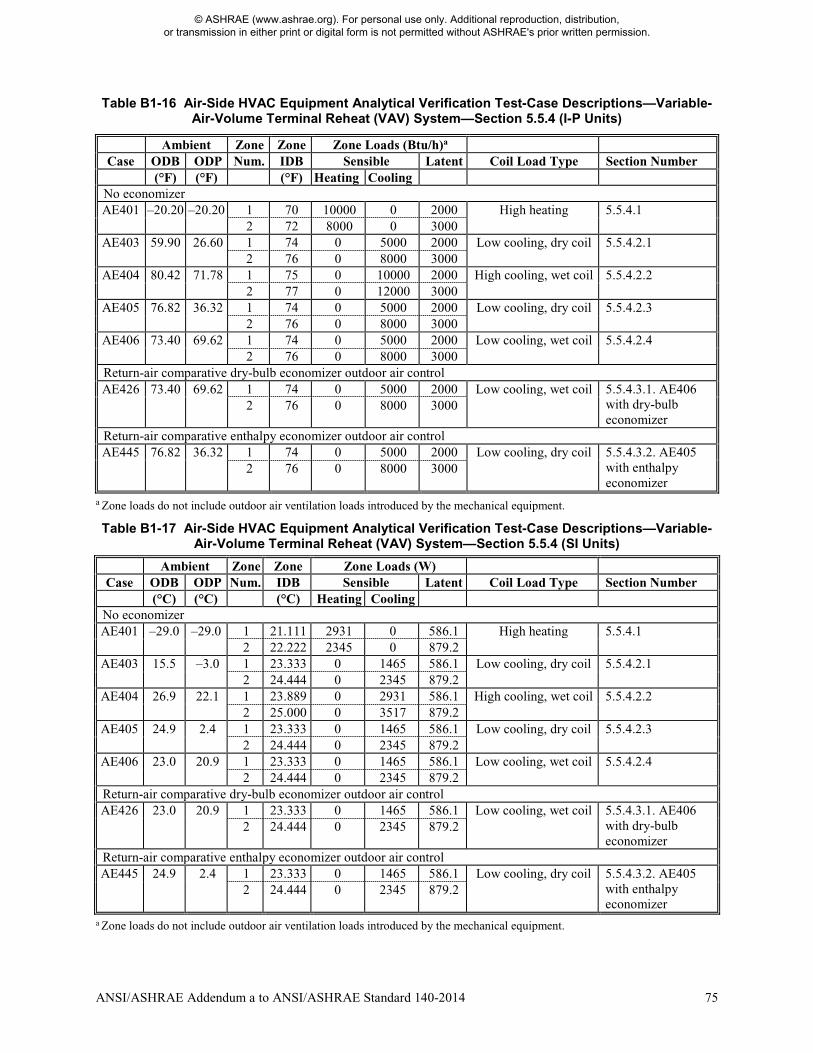
ANSI/ASHRAE Addendum a to ANSI/ASHRAE Standard 140-2014 75
Table B1-16 Air-Side HVAC Equipment Analytical Verification Test-Case Descriptions—Variable-Air-Volume Terminal Reheat (VAV) System—Section 5.5.4 (I-P Units)
Ambient Zone Zone Zone Loads (Btu/h)a Case ODB ODP Num. IDB Sensible Latent Coil Load Type Section Number
(°F) (°F) (°F) Heating Cooling No economizer AE401 –20.20 –20.20 1 70 10000 0 2000 High heating 5.5.4.1
2 72 8000 0 3000 AE403 59.90 26.60 1 74 0 5000 2000 Low cooling, dry coil 5.5.4.2.1
2 76 0 8000 3000 AE404 80.42 71.78 1 75 0 10000 2000 High cooling, wet coil 5.5.4.2.2
2 77 0 12000 3000 AE405 76.82 36.32 1 74 0 5000 2000 Low cooling, dry coil 5.5.4.2.3
2 76 0 8000 3000 AE406 73.40 69.62 1 74 0 5000 2000 Low cooling, wet coil 5.5.4.2.4
2 76 0 8000 3000 Return-air comparative dry-bulb economizer outdoor air control AE426 73.40 69.62 1 74 0 5000 2000 Low cooling, wet coil 5.5.4.3.1. AE406
with dry-bulb economizer
2 76 0 8000 3000
Return-air comparative enthalpy economizer outdoor air control AE445 76.82 36.32 1 74 0 5000 2000 Low cooling, dry coil 5.5.4.3.2. AE405
with enthalpy economizer
2 76 0 8000 3000
a Zone loads do not include outdoor air ventilation loads introduced by the mechanical equipment.
Table B1-17 Air-Side HVAC Equipment Analytical Verification Test-Case Descriptions—Variable-Air-Volume Terminal Reheat (VAV) System—Section 5.5.4 (SI Units)
Ambient Zone Zone Zone Loads (W) Case ODB ODP Num. IDB Sensible Latent Coil Load Type Section Number
(°C) (°C) (°C) Heating Cooling No economizer AE401 –29.0 –29.0 1 21.111 2931 0 586.1 High heating 5.5.4.1
2 22.222 2345 0 879.2 AE403 15.5 –3.0 1 23.333 0 1465 586.1 Low cooling, dry coil 5.5.4.2.1
2 24.444 0 2345 879.2 AE404 26.9 22.1 1 23.889 0 2931 586.1 High cooling, wet coil 5.5.4.2.2
2 25.000 0 3517 879.2 AE405 24.9 2.4 1 23.333 0 1465 586.1 Low cooling, dry coil 5.5.4.2.3
2 24.444 0 2345 879.2 AE406 23.0 20.9 1 23.333 0 1465 586.1 Low cooling, wet coil 5.5.4.2.4
2 24.444 0 2345 879.2 Return-air comparative dry-bulb economizer outdoor air control AE426 23.0 20.9 1 23.333 0 1465 586.1 Low cooling, wet coil 5.5.4.3.1. AE406
with dry-bulb economizer
2 24.444 0 2345 879.2
Return-air comparative enthalpy economizer outdoor air control AE445 24.9 2.4 1 23.333 0 1465 586.1 Low cooling, dry coil 5.5.4.3.2. AE405
with enthalpy economizer
2 24.444 0 2345 879.2
a Zone loads do not include outdoor air ventilation loads introduced by the mechanical equipment.
© ASHRAE (www.ashrae.org). For personal use only. Additional reproduction, distribution, or transmission in either print or digital form is not permitted without ASHRAE's prior written permission.
76 ANSI/ASHRAE Addendum a to ANSI/ASHRAE Standard 140-2014
Revise Informative Annex B10 as described below. (This annex is not part of the standard. It is merely informative and does not contain requirements necessary for conformance to the standard. It has not been processed according to the ANSI requirements for a standard and may contain material that has not been subject to public review or a consensus process. Unresolved objectors on informative material are not offered the right to appeal at ASHRAE or ANSI.) INFORMATIVE ANNEX B10 INSTRUCTIONS FOR WORKING WITH RESULTS SPREADSHEETS PROVIDED WITH THE STANDARD For the convenience of users, a printout of documentation for navigating the example results files is included below. Renumber Section B10.6 to Section B10.7 and revise as indicated. B10.76 Documentation for RESULTS7-2.XLS (given in RESULTS7-2.DOC). This file contains Tier 1 and Tier 2 test case example simulation results presented in Informative Annex B20. Table B10-86 presents an index of all sheets contained in the RESULTS7-2.XLS file. Insert new Section B10.6. B10.6 Documentation for RESULTS5-5FCSZ.XLSX and RESULTS5-5CVVV.XLSX (given in RESULTS5-5.DOCX). These files contain informative example results generated for the Section 5.5 air-side HVAC equipment performance test cases AE101 through AE245 (Sections 5.5.1 and 5.5.2) and AE301 through AE445 (Sections 5.5.3 and 5.5.4) as described in Informative Annex B16, Sections B16.7.1 and B16.7.2, respectively. Tables B10-6 and B10-7 present an index of all sheets contained in the RESULTS5-5FCSZ.XLSX and RESULTS5-5CVVV.XLSX files, respectively. The Read Me sheet in each results file provides a general overview of each file. Example results tables and figures are listed with location (sheet tab and cell range) in Informative Annex B16, Section B16.7 and also on the Table List and Figure List sheets in each results file. For each results file, new results can be imported to the YourData sheet and will automatically appear in the rightmost column of all tables and also in the graphic figures. The YourData sheet has been designed with the same data structure (data units, format, and position) as the standard output report spreadsheet Sec5-5out.XLSX file so that new results can be copied directly. Import data so that the software name entered in Cell C50 of Sec5-5out.XLSX is in C50 of sheet YourData. Check that the first output value (zone sensible heating load in kWh/h for AE101) is in YourData!C61. The Adding Results sheet has instructions for accomplishing this and also has a full tabulation of results locations. To print example results or example results with new user generated results go to the Title Page sheet and follow the instructions starting in Cell B5. Renumber Table B10-6 as B10-8; content of table is unchanged. TABLE B10-86 Index of Sheets in RESULTS7-2.XLS Insert new Tables B10-6 and B10-7.
© ASHRAE (www.ashrae.org). For personal use only. Additional reproduction, distribution, or transmission in either print or digital form is not permitted without ASHRAE's prior written permission.
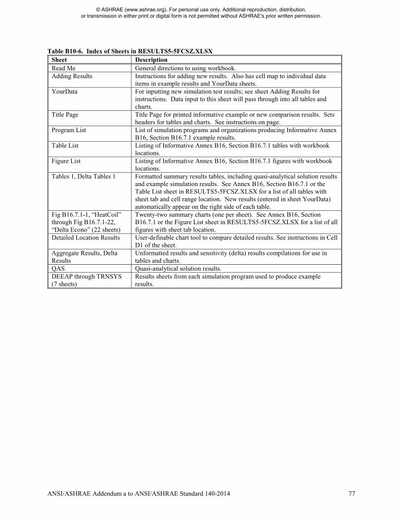
ANSI/ASHRAE Addendum a to ANSI/ASHRAE Standard 140-2014 77
Table B10-6. Index of Sheets in RESULTS5-5FCSZ.XLSX Sheet Description Read Me General directions to using workbook. Adding Results Instructions for adding new results. Also has cell map to individual data
items in example results and YourData sheets. YourData For inputting new simulation test results; see sheet Adding Results for
instructions. Data input to this sheet will pass through into all tables and charts.
Title Page Title Page for printed informative example or new comparison results. Sets headers for tables and charts. See instructions on page.
Program List List of simulation programs and organizations producing Informative Annex B16, Section B16.7.1 example results.
Table List Listing of Informative Annex B16, Section B16.7.1 tables with workbook locations.
Figure List Listing of Informative Annex B16, Section B16.7.1 figures with workbook locations.
Tables 1, Delta Tables 1 Formatted summary results tables, including quasi-analytical solution results and example simulation results. See Annex B16, Section B16.7.1 or the Table List sheet in RESULTS5-5FCSZ.XLSX for a list of all tables with sheet tab and cell range location. New results (entered in sheet YourData) automatically appear on the right side of each table.
Fig B16.7.1-1, “HeatCoil” through Fig B16.7.1-22, “Delta Econo” (22 sheets)
Twenty-two summary charts (one per sheet). See Annex B16, Section B16.7.1 or the Figure List sheet in RESULTS5-5FCSZ.XLSX for a list of all figures with sheet tab location.
Detailed Location Results User-definable chart tool to compare detailed results. See instructions in Cell D1 of the sheet.
Aggregate Results, Delta Results
Unformatted results and sensitivity (delta) results compilations for use in tables and charts.
QAS Quasi-analytical solution results. DEEAP through TRNSYS (7 sheets)
Results sheets from each simulation program used to produce example results.
© ASHRAE (www.ashrae.org). For personal use only. Additional reproduction, distribution, or transmission in either print or digital form is not permitted without ASHRAE's prior written permission.
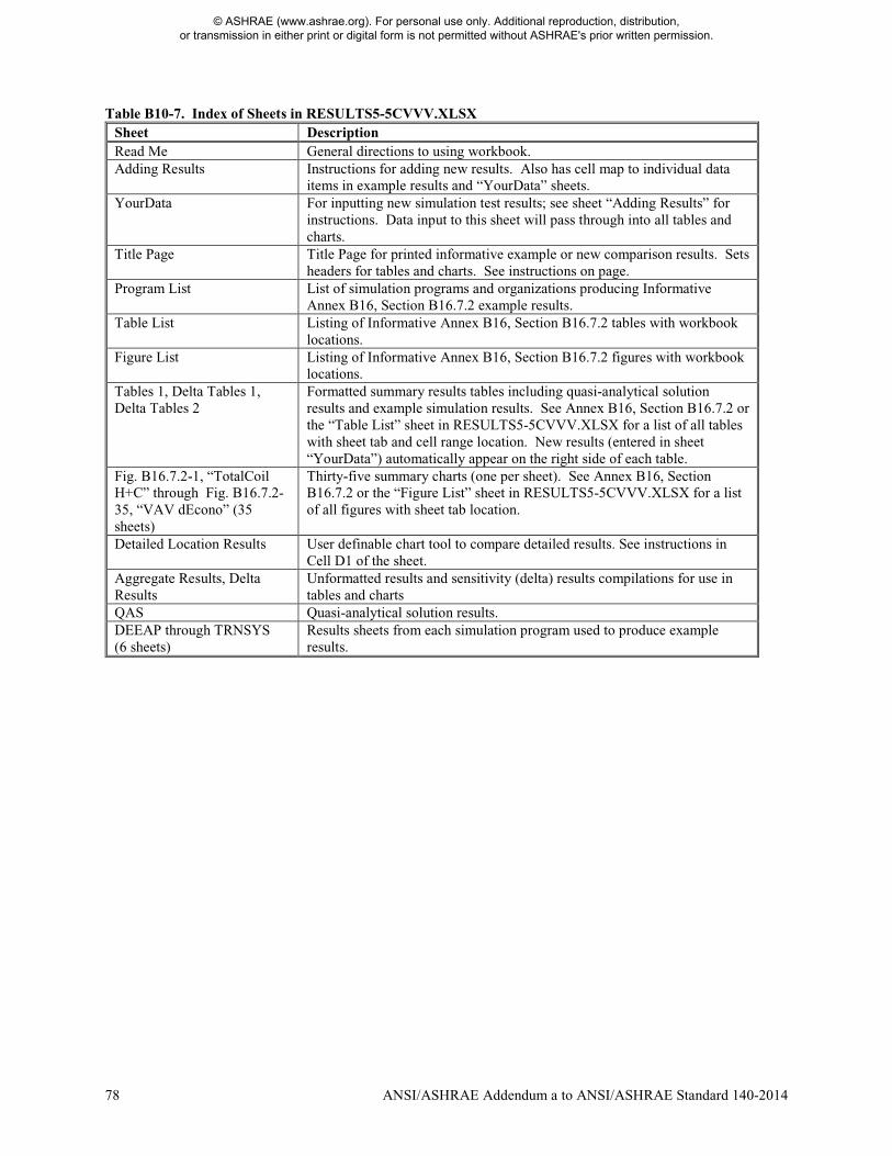
78 ANSI/ASHRAE Addendum a to ANSI/ASHRAE Standard 140-2014
Table B10-7. Index of Sheets in RESULTS5-5CVVV.XLSX Sheet Description Read Me General directions to using workbook. Adding Results Instructions for adding new results. Also has cell map to individual data
items in example results and “YourData” sheets. YourData For inputting new simulation test results; see sheet “Adding Results” for
instructions. Data input to this sheet will pass through into all tables and charts.
Title Page Title Page for printed informative example or new comparison results. Sets headers for tables and charts. See instructions on page.
Program List List of simulation programs and organizations producing Informative Annex B16, Section B16.7.2 example results.
Table List Listing of Informative Annex B16, Section B16.7.2 tables with workbook locations.
Figure List Listing of Informative Annex B16, Section B16.7.2 figures with workbook locations.
Tables 1, Delta Tables 1, Delta Tables 2
Formatted summary results tables including quasi-analytical solution results and example simulation results. See Annex B16, Section B16.7.2 or the “Table List” sheet in RESULTS5-5CVVV.XLSX for a list of all tables with sheet tab and cell range location. New results (entered in sheet “YourData”) automatically appear on the right side of each table.
Fig. B16.7.2-1, “TotalCoil H+C” through Fig. B16.7.2-35, “VAV dEcono” (35 sheets)
Thirty-five summary charts (one per sheet). See Annex B16, Section B16.7.2 or the “Figure List” sheet in RESULTS5-5CVVV.XLSX for a list of all figures with sheet tab location.
Detailed Location Results User definable chart tool to compare detailed results. See instructions in Cell D1 of the sheet.
Aggregate Results, Delta Results
Unformatted results and sensitivity (delta) results compilations for use in tables and charts
QAS Quasi-analytical solution results. DEEAP through TRNSYS (6 sheets)
Results sheets from each simulation program used to produce example results.
© ASHRAE (www.ashrae.org). For personal use only. Additional reproduction, distribution, or transmission in either print or digital form is not permitted without ASHRAE's prior written permission.
ANSI/ASHRAE Addendum a to ANSI/ASHRAE Standard 140-2014 79
(This annex is not part of this standard. It is merely informative and does not contain requirements necessary for conformance to the standard. It has not been processed according to the ANSI requirements for a standard and may contain material that has not been subject to public review or a consensus process. Unresolved objectors on informative material are not offered the right to appeal at ASHRAE or ANSI.) Revise title of Informative Annex B16 and portions of Sections B16.1 through B16.4 as indicated INFORMATIVE ANNEX B16 ANALYTICAL AND QUASI-ANALYTICAL SOLUTION RESULTS AND EXAMPLE SIMULATION RESULTS FOR HVAC EQUIPMENT PERFORMANCE TESTS OF SECTIONS 5.3, AND 5.4, AND 5.5 B16.1 Introduction. Example results from quasi-analytical solutions and various detailed building energy simulation programs applied to the tests of Sections 5.3, and 5.4, and 5.5 are presented in tabular and graphic form in the electronic media provided with this standard as follows:.
• Example results for Section 5.3 tests results are included with files RESULTS5-3Aa.PDF and RESULTS5-3B.PDF
• , and Section 5.4 test results are included in file RESULTS5-4.PDF • Section 5.5 test results are included in files RESULTS5-5FCSZ.PDF and RESULTS5-5CVVV.PDF.
A listing of the tables and figures in these files can be found in Sections B16.5, B16.6, and B16.76. These results can be used for a comparison with the software being tested. Alternatively, a user can run a number of different programs through the standard method of test or generate their own quasi-analytical solution results and draw comparisons from those results independently or in conjunction with the results listed here. In either case, when making comparisons the user should employ the diagnostic logic presented in Informative Annex B9. For convenience to users who wish to plot or tabulate their results along with the analytical and quasi-analytical solution results and example simulation results the spreadsheet files RESULTS5-3A.XLS, RESULTS5-3B.XLS, and RESULTS5-4.XLS, RESULTS5-5FCSZ.XLSX, and RESULTS5-5CVVV.XLSX are included in the accompanying electronic media. Spreadsheet navigation instructions are included in RESULTS5-3A.DOC, RESULTS5-3B.DOC, and RESULTS5-4.DOC, and RESULTS5-5.DOCX and have been printed out in Informative Annex B10, Sections B10.3, B10.4, B10.5, and B10.65, respectively, for convenience. B16.2 Importance of Analytical and Quasi-Analytical Solution Results. The results for the HVAC equipment performance tests of Sections B16.5.1, B16.6, and B16.76 include analytical and quasi-analytical solutions. Revise the third paragraph of Section B16.2 as indicated. The analytical and quasi-analytical solution results presented in selected parts of Annex B16 represent a mathematical and secondary mathematical truth standard, respectively. This allows identification of bugs in the software that would not otherwise be apparent from comparing software only to other software and therefore improves the diagnostic capabilities of the test procedure. Further discussion of how quasi-analytical and analytical solutions were developed is included in Informative Annex B17. Further discussion of overall validation methodology is included in Informative Annex B23 of this standard and in the 2013 ASHRAE Handbook—Fundamentals B-90, Chapter 19. B16.3.1 Results for Analytical Verification Tests Revise Section B16.3.1.1 as indicated. B16.3.1.1 Because the analytical and quasi-analytical solution results constitute a reliable set of theoretical results (a mathematical truth standard or secondary mathematical truth standard, respectively), the primary purpose of including simulation results for the CE100 through CE200, and HE100 through HE170, and AE101 through AE445 cases in Sections B16.5.1, B16.6, and B16.76 is to allow simulationists to compare their relative agreement (or disagreement) versus the quasi-analytical and analytical solution results to that for other simulation results. Perfect agreement among simulations and analytical or quasi-analytical solutions is not necessarily expected. The results give an indication of the degree of agreement that is possible between simulation results and the analytical or quasi-analytical solution results.
© ASHRAE (www.ashrae.org). For personal use only. Additional reproduction, distribution, or transmission in either print or digital form is not permitted without ASHRAE's prior written permission.
80 ANSI/ASHRAE Addendum a to ANSI/ASHRAE Standard 140-2014
B16.3.3 General Comments Regarding Simulation Results Revise Section B16.3.3.2 as shown. B16.3.3.2 For generating example simulation results presented in this annex, along with using consistent modeling methods, simulationists were requested to use the most detailed modeling methods their software allows. The example simulation results were the product of numerous iterations to incorporate clarifications to the test specification, simulation input file corrections, and simulation software improvements. Where improvements to simulation programs or simulation inputs were made as a result of running the tests, such improvements must have mathematical and physical bases and must be applied consistently across tests. Arbitrary modification of a simulation program’s input or internal code just for the purpose of more closely matching a given set of results is not allowed. For a summary of how quasi-analytical solution and simulation results were developed see Informative Annex B17. For more detailed information about these results see HVAC BESTEST Volume 1,B-9 HVAC BESTEST Volume 2,B-10 and HVAC BESTEST for Fuel-Fired Furnaces B-47,. and Airside HVAC BESTEST Volume 1.A-5 B16.4 Nomenclature. Revise existing Section B16.4 abbreviations entries as indicated. DOE-2.2 simulation model: DOE-2.2 version NT42j (see Table B17-2) (for Section B16.5.2), or DOE-2.2
version 48l (see Table B17-13) (for Sections B16.7.1 and B16.7.2); simulation model EnergyPlus simulation model: EnergyPlus 1.0.0.023 (see Table B17-1) (for Section B16.5.1), EnergyPlus
1.10.020 (see Table B17-2) (for Section B16.5.2), or EnergyPlus 1.0.2.008 (see Table B17-3) (for Section B16.6), or EnergyPlus 8.2.0 (see Table B17-13) (for Sections B16.7.1 and B16.7.2); simulation model
GARD modeler: GARD Analytics, Inc.; modeler NREL modeler: National Renewable Energy Laboratory: modeler for Sections B16.5.1, B16.5.2, B16,7.1,
and B16.7.2; quasi-analytical solution developer for Sections B16.7.1 and B16.7.2 TRNSYS simulation model: TRNSYS-TUD (see Table B17-2) (for Section B16.5.2), or TRNSYS with TESS
Libraries version 17.01.0028 (see Table B17-13) (for Sections B16.7.1 and B16.7.2); simulation model
Add the following abbreviations to the listing of Section B16.4. AAON AAON, Inc.; software developer and modeler CV constant-volume terminal reheat system (see Section 5.5.3) DB econo economizer with return-air comparative dry-bulb temperature control DEEAP Detailed Energy and Economic Analysis Program version 1.1.2 (see Table B17-13); simulation
model DeST Designer’s Simulation Toolkit version 2.0 (see Table B17-13); simulation model Econo economizer Enth. Eco economizer with return-air comparative enthalpy control FC fan-coil system (see Section 5.5.1) gda grams dry air IES Integrated Environmental Solutions, Ltd., software developer and modeler IES-VE Integrated Environmental Solutions—Virtual Environment version <VE>2014 Feature Pack 2 (see
Table B17-13); simulation model kgda kilograms dry air LBNL Lawrence Berkeley National Laboratory; modeler LCEM Life Cycle Energy Management version 3.10 (see Table B17-13); simulation model MLIT Ministry of Land, Infrastructure, Transportation and Tourism, Japan; software developer Org generic placeholder for additional modeler identification
© ASHRAE (www.ashrae.org). For personal use only. Additional reproduction, distribution, or transmission in either print or digital form is not permitted without ASHRAE's prior written permission.
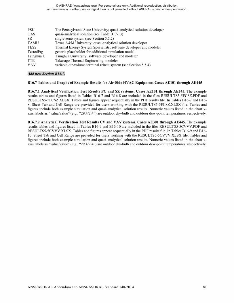
ANSI/ASHRAE Addendum a to ANSI/ASHRAE Standard 140-2014 81
PSU The Pennsylvania State University; quasi-analytical solution developer QAS quasi-analytical solution (see Table B17-13) SZ single-zone system (see Section 5.5.2) TAMU Texas A&M University; quasi-analytical solution developer TESS Thermal Energy System Specialists; software developer and modeler TestedPrg generic placeholder for additional simulation model Tsinghua U Tsinghua University; software developer and modeler TTE Takasago Thermal Engineering; modeler VAV variable-air-volume terminal reheat system (see Section 5.5.4) Add new Section B16.7. B16.7 Tables and Graphs of Example Results for Air-Side HVAC Equipment Cases AE101 through AE445 B16.7.1 Analytical Verification Test Results FC and SZ systems, Cases AE101 through AE245. The example results tables and figures listed in Tables B16-7 and B16-8 are included in the files RESULTS5-5FCSZ.PDF and RESULTS5-5FCSZ.XLSX. Tables and figures appear sequentially in the PDF results file. In Tables B16-7 and B16-8, Sheet Tab and Cell Range are provided for users working with the RESULTS5-5FCSZ.XLSX file. Tables and figures include both example simulation and quasi-analytical solution results. Numeric values listed in the chart x-axis labels as “value/value” (e.g., “29.4/2.4”) are outdoor dry-bulb and outdoor dew-point temperatures, respectively. B16.7.2 Analytical Verification Test Results CV and VAV systems, Cases AE301 through AE445. The example results tables and figures listed in Tables B16-9 and B16-10 are included in the files RESULTS5-5CVVV.PDF and RESULTS5-5CVVV.XLSX. Tables and figures appear sequentially in the PDF results file. In Tables B16-9 and B16-10, Sheet Tab and Cell Range are provided for users working with the RESULTS5-5CVVV.XLSX file. Tables and figures include both example simulation and quasi-analytical solution results. Numeric values listed in the chart x-axis labels as “value/value” (e.g., “29.4/2.4”) are outdoor dry-bulb and outdoor dew-point temperatures, respectively.
© ASHRAE (www.ashrae.org). For personal use only. Additional reproduction, distribution, or transmission in either print or digital form is not permitted without ASHRAE's prior written permission.
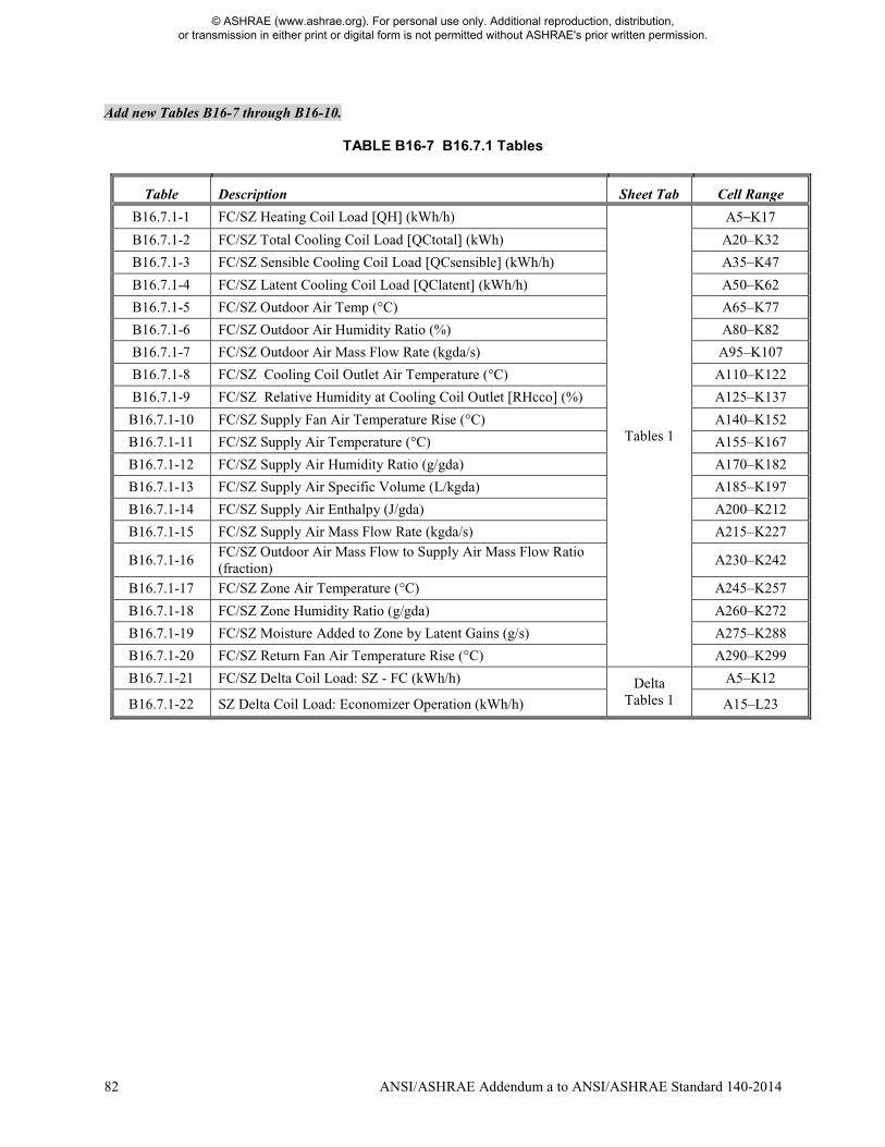
82 ANSI/ASHRAE Addendum a to ANSI/ASHRAE Standard 140-2014
Add new Tables B16-7 through B16-10.
TABLE B16-7 B16.7.1 Tables
Table Description Sheet Tab Cell Range
B16.7.1-1 FC/SZ Heating Coil Load [QH] (kWh/h)
Tables 1
A5–K17
B16.7.1-2 FC/SZ Total Cooling Coil Load [QCtotal] (kWh) A20–K32
B16.7.1-3 FC/SZ Sensible Cooling Coil Load [QCsensible] (kWh/h) A35–K47
B16.7.1-4 FC/SZ Latent Cooling Coil Load [QClatent] (kWh/h) A50–K62
B16.7.1-5 FC/SZ Outdoor Air Temp (°C) A65–K77
B16.7.1-6 FC/SZ Outdoor Air Humidity Ratio (%) A80–K82
B16.7.1-7 FC/SZ Outdoor Air Mass Flow Rate (kgda/s) A95–K107
B16.7.1-8 FC/SZ Cooling Coil Outlet Air Temperature (°C) A110–K122
B16.7.1-9 FC/SZ Relative Humidity at Cooling Coil Outlet [RHcco] (%) A125–K137
B16.7.1-10 FC/SZ Supply Fan Air Temperature Rise (°C) A140–K152
B16.7.1-11 FC/SZ Supply Air Temperature (°C) A155–K167
B16.7.1-12 FC/SZ Supply Air Humidity Ratio (g/gda) A170–K182
B16.7.1-13 FC/SZ Supply Air Specific Volume (L/kgda) A185–K197
B16.7.1-14 FC/SZ Supply Air Enthalpy (J/gda) A200–K212
B16.7.1-15 FC/SZ Supply Air Mass Flow Rate (kgda/s) A215–K227
B16.7.1-16 FC/SZ Outdoor Air Mass Flow to Supply Air Mass Flow Ratio (fraction)
A230–K242
B16.7.1-17 FC/SZ Zone Air Temperature (°C) A245–K257
B16.7.1-18 FC/SZ Zone Humidity Ratio (g/gda) A260–K272
B16.7.1-19 FC/SZ Moisture Added to Zone by Latent Gains (g/s) A275–K288
B16.7.1-20 FC/SZ Return Fan Air Temperature Rise (°C) A290–K299
B16.7.1-21 FC/SZ Delta Coil Load: SZ - FC (kWh/h) Delta Tables 1
A5–K12
B16.7.1-22 SZ Delta Coil Load: Economizer Operation (kWh/h) A15–L23
© ASHRAE (www.ashrae.org). For personal use only. Additional reproduction, distribution, or transmission in either print or digital form is not permitted without ASHRAE's prior written permission.
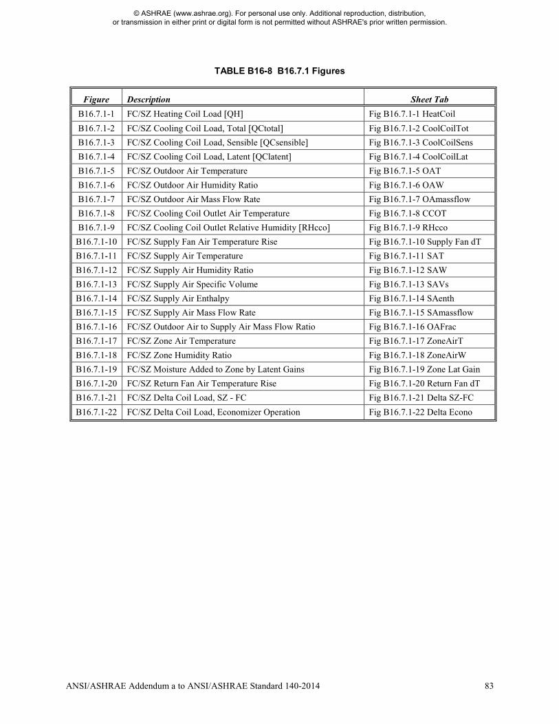
ANSI/ASHRAE Addendum a to ANSI/ASHRAE Standard 140-2014 83
TABLE B16-8 B16.7.1 Figures
Figure Description Sheet Tab
B16.7.1-1 FC/SZ Heating Coil Load [QH] Fig B16.7.1-1 HeatCoil
B16.7.1-2 FC/SZ Cooling Coil Load, Total [QCtotal] Fig B16.7.1-2 CoolCoilTot
B16.7.1-3 FC/SZ Cooling Coil Load, Sensible [QCsensible] Fig B16.7.1-3 CoolCoilSens
B16.7.1-4 FC/SZ Cooling Coil Load, Latent [QClatent] Fig B16.7.1-4 CoolCoilLat
B16.7.1-5 FC/SZ Outdoor Air Temperature Fig B16.7.1-5 OAT
B16.7.1-6 FC/SZ Outdoor Air Humidity Ratio Fig B16.7.1-6 OAW
B16.7.1-7 FC/SZ Outdoor Air Mass Flow Rate Fig B16.7.1-7 OAmassflow
B16.7.1-8 FC/SZ Cooling Coil Outlet Air Temperature Fig B16.7.1-8 CCOT
B16.7.1-9 FC/SZ Cooling Coil Outlet Relative Humidity [RHcco] Fig B16.7.1-9 RHcco
B16.7.1-10 FC/SZ Supply Fan Air Temperature Rise Fig B16.7.1-10 Supply Fan dT
B16.7.1-11 FC/SZ Supply Air Temperature Fig B16.7.1-11 SAT
B16.7.1-12 FC/SZ Supply Air Humidity Ratio Fig B16.7.1-12 SAW
B16.7.1-13 FC/SZ Supply Air Specific Volume Fig B16.7.1-13 SAVs
B16.7.1-14 FC/SZ Supply Air Enthalpy Fig B16.7.1-14 SAenth
B16.7.1-15 FC/SZ Supply Air Mass Flow Rate Fig B16.7.1-15 SAmassflow
B16.7.1-16 FC/SZ Outdoor Air to Supply Air Mass Flow Ratio Fig B16.7.1-16 OAFrac
B16.7.1-17 FC/SZ Zone Air Temperature Fig B16.7.1-17 ZoneAirT
B16.7.1-18 FC/SZ Zone Humidity Ratio Fig B16.7.1-18 ZoneAirW
B16.7.1-19 FC/SZ Moisture Added to Zone by Latent Gains Fig B16.7.1-19 Zone Lat Gain
B16.7.1-20 FC/SZ Return Fan Air Temperature Rise Fig B16.7.1-20 Return Fan dT
B16.7.1-21 FC/SZ Delta Coil Load, SZ - FC Fig B16.7.1-21 Delta SZ-FC
B16.7.1-22 FC/SZ Delta Coil Load, Economizer Operation Fig B16.7.1-22 Delta Econo
© ASHRAE (www.ashrae.org). For personal use only. Additional reproduction, distribution, or transmission in either print or digital form is not permitted without ASHRAE's prior written permission.
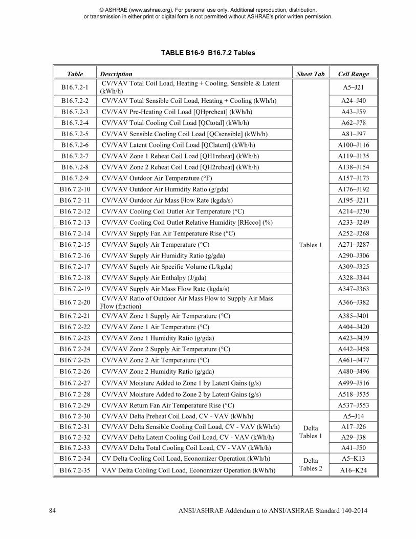
84 ANSI/ASHRAE Addendum a to ANSI/ASHRAE Standard 140-2014
TABLE B16-9 B16.7.2 Tables
Table Description Sheet Tab Cell Range
B16.7.2-1 CV/VAV Total Coil Load, Heating + Cooling, Sensible & Latent (kWh/h)
Tables 1
A5–J21
B16.7.2-2 CV/VAV Total Sensible Coil Load, Heating + Cooling (kWh/h) A24–J40
B16.7.2-3 CV/VAV Pre-Heating Coil Load [QHpreheat] (kWh/h) A43–J59
B16.7.2-4 CV/VAV Total Cooling Coil Load [QCtotal] (kWh/h) A62–J78
B16.7.2-5 CV/VAV Sensible Cooling Coil Load [QCsensible] (kWh/h) A81–J97
B16.7.2-6 CV/VAV Latent Cooling Coil Load [QClatent] (kWh/h) A100–J116
B16.7.2-7 CV/VAV Zone 1 Reheat Coil Load [QH1reheat] (kWh/h) A119–J135
B16.7.2-8 CV/VAV Zone 2 Reheat Coil Load [QH2reheat] (kWh/h) A138–J154
B16.7.2-9 CV/VAV Outdoor Air Temperature (°F) A157–J173
B16.7.2-10 CV/VAV Outdoor Air Humidity Ratio (g/gda) A176–J192
B16.7.2-11 CV/VAV Outdoor Air Mass Flow Rate (kgda/s) A195–J211
B16.7.2-12 CV/VAV Cooling Coil Outlet Air Temperature (°C) A214–J230
B16.7.2-13 CV/VAV Cooling Coil Outlet Relative Humidity [RHcco] (%) A233–J249
B16.7.2-14 CV/VAV Supply Fan Air Temperature Rise (°C) A252–J268
B16.7.2-15 CV/VAV Supply Air Temperature (°C) A271–J287
B16.7.2-16 CV/VAV Supply Air Humidity Ratio (g/gda) A290–J306
B16.7.2-17 CV/VAV Supply Air Specific Volume (L/kgda) A309–J325
B16.7.2-18 CV/VAV Supply Air Enthalpy (J/gda) A328–J344
B16.7.2-19 CV/VAV Supply Air Mass Flow Rate (kgda/s) A347–J363
B16.7.2-20 CV/VAV Ratio of Outdoor Air Mass Flow to Supply Air Mass Flow (fraction)
A366–J382
B16.7.2-21 CV/VAV Zone 1 Supply Air Temperature (°C) A385–J401
B16.7.2-22 CV/VAV Zone 1 Air Temperature (°C) A404–J420
B16.7.2-23 CV/VAV Zone 1 Humidity Ratio (g/gda) A423–J439
B16.7.2-24 CV/VAV Zone 2 Supply Air Temperature (°C) A442–J458
B16.7.2-25 CV/VAV Zone 2 Air Temperature (°C) A461–J477
B16.7.2-26 CV/VAV Zone 2 Humidity Ratio (g/gda) A480–J496
B16.7.2-27 CV/VAV Moisture Added to Zone 1 by Latent Gains (g/s) A499–J516
B16.7.2-28 CV/VAV Moisture Added to Zone 2 by Latent Gains (g/s) A518–J535
B16.7.2-29 CV/VAV Return Fan Air Temperature Rise (°C) A537–J553
B16.7.2-30 CV/VAV Delta Preheat Coil Load, CV - VAV (kWh/h)
Delta Tables 1
A5–J14
B16.7.2-31 CV/VAV Delta Sensible Cooling Coil Load, CV - VAV (kWh/h) A17–J26
B16.7.2-32 CV/VAV Delta Latent Cooling Coil Load, CV - VAV (kWh/h) A29–J38
B16.7.2-33 CV/VAV Delta Total Cooling Coil Load, CV - VAV (kWh/h) A41–J50
B16.7.2-34 CV Delta Cooling Coil Load, Economizer Operation (kWh/h) Delta Tables 2
A5–K13
B16.7.2-35 VAV Delta Cooling Coil Load, Economizer Operation (kWh/h) A16–K24
© ASHRAE (www.ashrae.org). For personal use only. Additional reproduction, distribution, or transmission in either print or digital form is not permitted without ASHRAE's prior written permission.
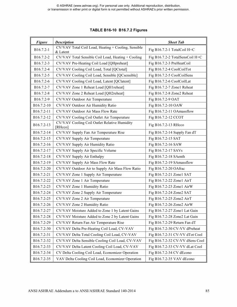
ANSI/ASHRAE Addendum a to ANSI/ASHRAE Standard 140-2014 85
TABLE B16-10 B16.7.2 Figures
Figure Description Sheet Tab
B16.7.2-1 CV/VAV Total Coil Load, Heating + Cooling, Sensible & Latent
Fig B16.7.2-1 TotalCoil H+C
B16.7.2-2 CV/VAV Total Sensible Coil Load, Heating + Cooling Fig B16.7.2-2 TotalSensCoil H+C
B16.7.2-3 CV/VAV Pre-Heating Coil Load [QHpreheat] Fig B16.7.2-3 PreHeatCoil
B16.7.2-4 CV/VAV Cooling Coil Load, Total [QCtotal] Fig B16.7.2-4 CoolCoilTot
B16.7.2-5 CV/VAV Cooling Coil Load, Sensible [QCsensible] Fig B16.7.2-5 CoolCoilSens
B16.7.2-6 CV/VAV Cooling Coil Load, Latent [QClatent] Fig B16.7.2-6 CoolCoilLat
B16.7.2-7 CV/VAV Zone 1 Reheat Load [QH1reheat] Fig B16.7.2-7 Zone1 Reheat
B16.7.2-8 CV/VAV Zone 2 Reheat Load [QH2reheat] Fig B16.7.2-8 Zone2 Reheat
B16.7.2-9 CV/VAV Outdoor Air Temperature Fig B16.7.2-9 OAT
B16.7.2-10 CV/VAV Outdoor Air Humidity Ratio Fig B16.7.2-10 OAW
B16.7.2-11 CV/VAV Outdoor Air Mass Flow Rate Fig B16.7.2-11 OAmassflow
B16.7.2-12 CV/VAV Cooling Coil Outlet Air Temperature Fig B16.7.2-12 CCOT
B16.7.2-13 CV/VAV Cooling Coil Outlet Relative Humidity [RHcco]
Fig B16.7.2-13 RHcco
B16.7.2-14 CV/VAV Supply Fan Air Temperature Rise Fig B16.7.2-14 Supply Fan dT
B16.7.2-15 CV/VAV Supply Air Temperature Fig B16.7.2-15 SAT
B16.7.2-16 CV/VAV Supply Air Humidity Ratio Fig B16.7.2-16 SAW
B16.7.2-17 CV/VAV Supply Air Specific Volume Fig B16.7.2-17 SAVs
B16.7.2-18 CV/VAV Supply Air Enthalpy Fig B16.7.2-18 SAenth
B16.7.2-19 CV/VAV Supply Air Mass Flow Rate Fig B16.7.2-19 SAmassflow
B16.7.2-20 CV/VAV Outdoor Air to Supply Air Mass Flow Ratio Fig B16.7.2-20 OAfrac
B16.7.2-21 CV/VAV Zone 1 Supply Air Temperature Fig B16.7.2-21 Zone1 SAT
B16.7.2-22 CV/VAV Zone 1 Air Temperature Fig B16.7.2-22 Zone1 AirT
B16.7.2-23 CV/VAV Zone 1 Humidity Ratio Fig B16.7.2-23 Zone1 AirW
B16.7.2-24 CV/VAV Zone 2 Supply Air Temperature Fig B16.7.2-24 Zone2 SAT
B16.7.2-25 CV/VAV Zone 2 Air Temperature Fig B16.7.2-25 Zone2 AirT
B16.7.2-26 CV/VAV Zone 2 Humidity Ratio Fig B16.7.2-26 Zone2 AirW
B16.7.2-27 CV/VAV Moisture Added to Zone 1 by Latent Gains Fig B16.7.2-27 Zone1 Lat Gain
B16.7.2-28 CV/VAV Moisture Added to Zone 2 by Latent Gains Fig B16.7.2-28 Zone2 Lat Gain
B16.7.2-29 CV/VAV Return Fan Air Temperature Rise Fig B16.7.2-29 Return Fan dT
B16.7.2-30 CV/VAV Delta Pre-Heating Coil Load, CV-VAV Fig B16.7.2-30 CV-VV dPreheat
B16.7.2-31 CV/VAV Delta Total Cooling Coil Load, CV-VAV Fig B16.7.2-31 CV-VV dTot Cool
B16.7.2-32 CV/VAV Delta Sensible Cooling Coil Load, CV-VAV Fig B16.7.2-32 CV-VV dSens Cool
B16.7.2-33 CV/VAV Delta Latent Cooling Coil Load, CV-VAV Fig B16.7.2-33 CV-VV dLat Cool
B16.7.2-34 CV Delta Cooling Coil Load, Economizer Operation Fig B16.7.2-34 CV dEcono
B16.7.2-35 VAV Delta Cooling Coil Load, Economizer Operation Fig B16.7.2-35 VAV dEcono
© ASHRAE (www.ashrae.org). For personal use only. Additional reproduction, distribution, or transmission in either print or digital form is not permitted without ASHRAE's prior written permission.

86 ANSI/ASHRAE Addendum a to ANSI/ASHRAE Standard 140-2014
(This annex is not part of this standard. It is merely informative and does not contain requirements necessary for conformance to the standard. It has not been processed according to the ANSI requirements for a standard and may contain material that has not been subject to public review or a consensus process. Unresolved objectors on informative material are not offered the right to appeal at ASHRAE or ANSI.) Revise title of Informative Annex B17 as indicated. INFORMATIVE ANNEX B17 PRODUCTION OF ANALYTICAL AND QUASI-ANALYTICAL SOLUTION RESULTS AND EXAMPLE SIMULATION RESULTS FOR HVAC EQUIPMENT PERFORMANCE TESTS OF SECTIONS 5.3, AND 5.4, and 5.5 Add new Section B17.3. B17.3 For Air-Side HVAC Equipment Analytical Verification Tests, Cases AE101 through AE445 B17.3.1 Introduction B17.3.1.1 The full discussion regarding production of quasi-analytical solution results and example simulation results is included in Airside HVAC BESTEST A-5. Portions of that discussion have been included here. The quasi-analytical solutions and programs used to generate the example simulation results are listed in Table B17-13. Table B17-13 is organized similarly to Table B17-1; see Section B17.1.1.1.2 for a description of the information included in the table. B17.3.1.2 The availability of quasi-analytical solutions (see Section B17.3.2) greatly helped to identify and correct errors in the simulations, such that errors are minimized in the final simulation results. Also, to minimize the potential for user error in the simulations, when feasible more than one modeler developed input files for each program. Improvements to simulation programs or simulation inputs were subject to requirements described in Section B17.1.1.1.4. B17.3.1.3 The quasi-analytical solutions workbook and input files used to generate the simulation results are provided with the accompanying electronic media; see the README*.DOC file. B17.3.2 Quasi-Analytical Solution Results. The quasi-analytical solution results given in Informative Annex B16, Section B16.7 were developed as part of a collaboration with the ASHRAE Standard 140 committee (SSPC 140) and other international software developers and participants. The importance of having analytical or quasi-analytical solution results is discussed in Annex B16, Section B16.2. The quasi-analytical solutions are based on the initial work of ASHRAE RP 865 A-7, with further vetting and development by National Renewable Energy Laboratory (NREL) to merge the original RP 865 solution spreadsheets into a single set of quasi-analytical solutions. The vetting process followed the procedure for developing analytical and quasi-analytical solutions defined by NREL in previous work,B-
9 and involved checking all original equations by a third independent analyst. Spreadsheet results disagreements from the original work were reconciled by the third analyst; where needed, some details were reconciled in collaboration with the original solution developers. The vetting process also included comparison with previous solutions as quasi-analytical solution versions progressed. The quasi-analytical solution results also have good agreement with two of the simulation models that were able to most closely match the assumptions of the quasi-analytical solution, and observable differences between the quasi-analytical solutions and the other simulation programs were explainable by modeling assumptions of those programs, consistent with the test-case diagnostics. Perfect agreement among simulations and the quasi-analytical solution results is not necessarily expected because many programs contain simplifying assumptions to ease calculation burden (e.g., constant air density), and the quasi-analytical solutions contain idealized simplifying assumptions (in order to be solved analytically) that cannot always be exactly reproduced by some simulation programs that are conceived and hardcoded with more realistic assumptions. Full documentation of the quasi-analytical solutions (including final spreadsheet files) and their development are included in Airside HVAC BESTESTA-5, Part II and its related accompanying files.
© ASHRAE (www.ashrae.org). For personal use only. Additional reproduction, distribution, or transmission in either print or digital form is not permitted without ASHRAE's prior written permission.
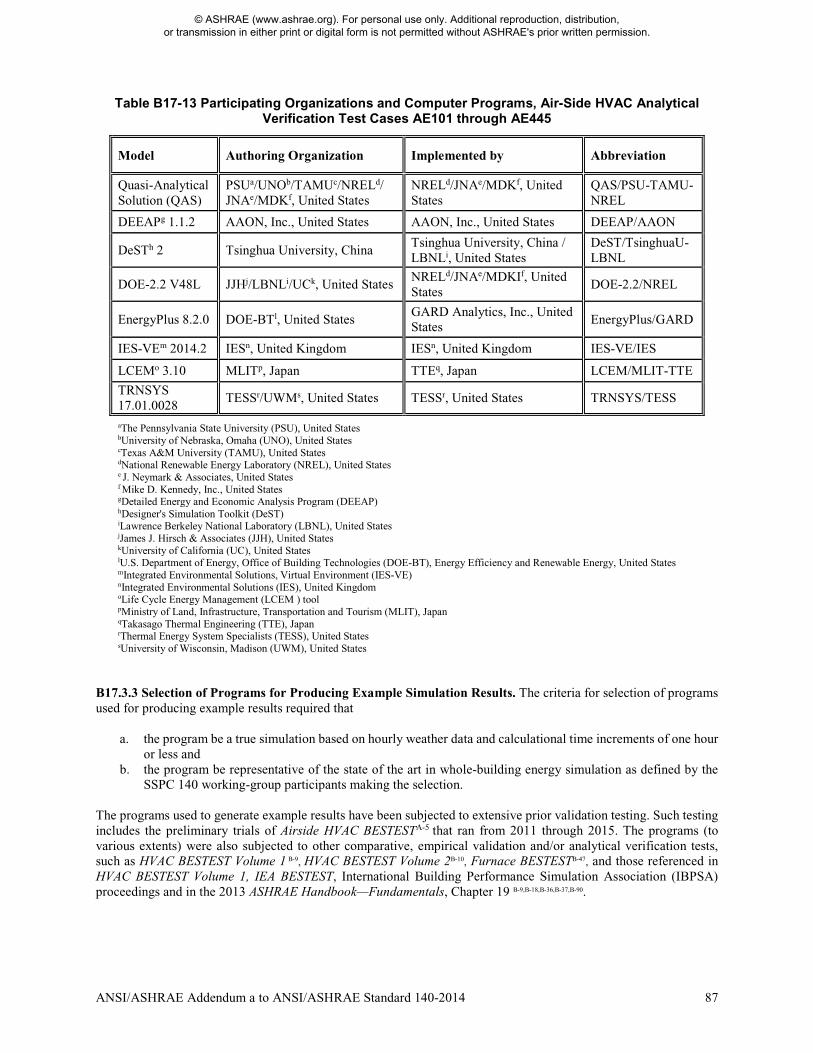
ANSI/ASHRAE Addendum a to ANSI/ASHRAE Standard 140-2014 87
Table B17-13 Participating Organizations and Computer Programs, Air-Side HVAC Analytical Verification Test Cases AE101 through AE445
Model Authoring Organization Implemented by Abbreviation
Quasi-Analytical Solution (QAS)
PSUa/UNOb/TAMUc/NRELd/ JNAe/MDKf, United States
NRELd/JNAe/MDKf, United States
QAS/PSU-TAMU-NREL
DEEAPg 1.1.2 AAON, Inc., United States AAON, Inc., United States DEEAP/AAON
DeSTh 2 Tsinghua University, China Tsinghua University, China / LBNLi, United States
DeST/TsinghuaU-LBNL
DOE-2.2 V48L JJHj/LBNLi/UCk, United States NRELd/JNAe/MDKIf, United States
DOE-2.2/NREL
EnergyPlus 8.2.0 DOE-BTl, United States GARD Analytics, Inc., United States
EnergyPlus/GARD
IES-VEm 2014.2 IESn, United Kingdom IESn, United Kingdom IES-VE/IES
LCEMo 3.10 MLITp, Japan TTEq, Japan LCEM/MLIT-TTE
TRNSYS 17.01.0028
TESSr/UWMs, United States TESSr, United States TRNSYS/TESS
aThe Pennsylvania State University (PSU), United States bUniversity of Nebraska, Omaha (UNO), United States cTexas A&M University (TAMU), United States dNational Renewable Energy Laboratory (NREL), United States e J. Neymark & Associates, United States f Mike D. Kennedy, Inc., United States gDetailed Energy and Economic Analysis Program (DEEAP) hDesigner's Simulation Toolkit (DeST) iLawrence Berkeley National Laboratory (LBNL), United States jJames J. Hirsch & Associates (JJH), United States kUniversity of California (UC), United States lU.S. Department of Energy, Office of Building Technologies (DOE-BT), Energy Efficiency and Renewable Energy, United States mIntegrated Environmental Solutions, Virtual Environment (IES-VE) nIntegrated Environmental Solutions (IES), United Kingdom oLife Cycle Energy Management (LCEM ) tool pMinistry of Land, Infrastructure, Transportation and Tourism (MLIT), Japan qTakasago Thermal Engineering (TTE), Japan rThermal Energy System Specialists (TESS), United States sUniversity of Wisconsin, Madison (UWM), United States
B17.3.3 Selection of Programs for Producing Example Simulation Results. The criteria for selection of programs used for producing example results required that
a. the program be a true simulation based on hourly weather data and calculational time increments of one hour or less and
b. the program be representative of the state of the art in whole-building energy simulation as defined by the SSPC 140 working-group participants making the selection.
The programs used to generate example results have been subjected to extensive prior validation testing. Such testing includes the preliminary trials of Airside HVAC BESTESTA-5 that ran from 2011 through 2015. The programs (to various extents) were also subjected to other comparative, empirical validation and/or analytical verification tests, such as HVAC BESTEST Volume 1 B-9, HVAC BESTEST Volume 2B-10, Furnace BESTESTB-47, and those referenced in HVAC BESTEST Volume 1, IEA BESTEST, International Building Performance Simulation Association (IBPSA) proceedings and in the 2013 ASHRAE Handbook—Fundamentals, Chapter 19 B-9,B-18,B-36,B-37,B-90.
© ASHRAE (www.ashrae.org). For personal use only. Additional reproduction, distribution, or transmission in either print or digital form is not permitted without ASHRAE's prior written permission.
88 ANSI/ASHRAE Addendum a to ANSI/ASHRAE Standard 140-2014
In Annex B20, update cross-reference of Informative Annex B10, Sections B10.6 to B10.7 as shown. (This annex is not part of the standard. It is merely informative and does not contain requirements necessary for conformance to the standard. It has not been processed according to the ANSI requirements for a standard and may contain material that has not been subject to public review or a consensus process. Unresolved objectors on informative material are not offered the right to appeal at ASHRAE or ANSI.) INFORMATIVE ANNEX B20 EXAMPLE RESULTS FOR SECTION 7 TEST PROCEDURES For the convenience to users who wish to plot or tabulate their results along with the example results, an electronic version of the example results has been included with the file RESULTS7-2.XLS on the accompanying electronic media. Documentation regarding RESULTS7-2.XLS is included in RESULTS7-2.DOC; a summary printout is included in Informative Annex B10, Section B10.76.
© ASHRAE (www.ashrae.org). For personal use only. Additional reproduction, distribution, or transmission in either print or digital form is not permitted without ASHRAE's prior written permission.

ANSI/ASHRAE Addendum a to ANSI/ASHRAE Standard 140-2014 89
Add new References to Annex B24 as shown. (This annex is not part of the standard. It is merely informative and does not contain requirements necessary for conformance to the standard. It has not been processed according to the ANSI requirements for a standard and may contain material that has not been subject to public review or a consensus process. Unresolved objectors on informative material are not offered the right to appeal at ASHRAE or ANSI.) INFORMATIVE ANNEX B24 INFORMATIVE REFERENCES A-1ASHRAE. (2012). Handbook of HVAC Systems and Equipment. Atlanta, Georgia, U.S.A.: American Society of Heating, Refrigerating and Air-Conditioning Engineers. A-2AMCA/ASHRAE. (1985). Laboratory Methods of Testing Fans for Certified Aerodynamic Performance Rating. ANSI/AMCA 210-85 or ANSI/ASHRAE 51-85. Arlington Heights, Illinois, U.S.A.: Air Movement and Control Association International, Inc. Atlanta, Georgia, U.S.A.: American Society of Heating, Refrigerating, and Air-Conditioning Engineers. See Section 9.8.2. A-3AMCA/ASHRAE. (2007). Laboratory Methods of Testing Fans for Certified Aerodynamic Performance Rating. ANSI/AMCA 210-07 or ANSI/ASHRAE 51-07. Arlington Heights, Illinois, U.S.A.: Air Movement and Control Association International, Inc. Atlanta, Georgia, U.S.A.: American Society of Heating, Refrigerating, and Air-Conditioning Engineers. A-4McQuiston, F.; Parker, J. (1994). HVAC Analysis and Design. Fourth Edition. New York, New York, U.S.A.: John Wiley & Sons. See Chapter 12.
A-5Neymark, J.; Kennedy, M.; Judkoff, R.; Gall, J.; Henninger, R.; Hong, T.; Knebel, D.; McDowell, T.; Witte, M.; Yan, D.; Zhou, X. (2016). Airside HVAC BESTEST: Adaptation of ASHRAE RP 865 Airside HVAC Equipment Modeling Test Cases for ASHRAE Standard 140, Volume 1: Cases AE101 – AE445. NREL/TP-5500-66000. Golden, Colorado, U.S.A.: National Renewable Energy Laboratory. http://www.nrel.gov/docs/fy16osti/66000.pdf. A-6ASHRAE. (2009). Handbook of Fundamentals. Atlanta, Georgia, U.S.A.: American Society of Heating, Refrigerating and Air-Conditioning Engineers. Regarding conversion factors, see Chapter 38; regarding psychrometrics, see Chapter 1; regarding surface heat transfer coefficients, see Chapter 26. A-7Yuill, G.K.; J.S. Haberl. (2002). Development of Accuracy Tests For Mechanical System Simulation. Final Report for ASHRAE 865-RP. Omaha, NE: University of Nebraska Architectural Engineering Program. A-8Judkoff, R.; Neymark, J. (1995). International Energy Agency Building Energy Simulation Test (BESTEST) and Diagnostic Method. NREL/TP-472-6231, Golden, Colorado, U.S.A.: National Renewable Energy Laboratory. www.nrel.gov/docs/legosti/old/6231/pdf. (See Appendix D.) A-9Walton, G. (1983). Thermal Analysis Research Program Reference Manual (TARP). NBSIR 83-2655. Washington, D.C.: National Bureau of Standards (now called National Institute of Standards and Technology). A-10Herrmann, S.; Kretzschmar, H.-J.; Gatley, D.P. (2011). Thermodynamic Properties of Real Moist Air, Dry Air, Steam, Water, and Ice. Final report for ASHRAE RP-1485. Zittau, Germany: Zittau/Goerlitz University of Applied Sciences, Department of Technical Thermodynamics.
A-11Kretzschmar, H.-J.; Herrmann, S.; Stoecker, I.; Kunick, M.; Nicke, M.; Gatley, D.P. (2011). ASHRAE User’s Guide for LibHuAirProp Library of Psychrometric, Thermodynamic, and Transport Properties for Real Humid Air, Steam, Water and Ice. Atlanta, Georgia, U.S.A.: American Society of Heating, Refrigerating and Air-Conditioning Engineers.
© ASHRAE (www.ashrae.org). For personal use only. Additional reproduction, distribution, or transmission in either print or digital form is not permitted without ASHRAE's prior written permission.

© ASHRAE (www.ashrae.org). For personal use only. Additional reproduction, distribution, or transmission in either print or digital form is not permitted without ASHRAE's prior written permission.
POLICY STATEMENT DEFINING ASHRAE’S CONCERNFOR THE ENVIRONMENTAL IMPACT OF ITS ACTIVITIES
ASHRAE is concerned with the impact of its members’ activities on both the indoor and outdoor environment.ASHRAE’s members will strive to minimize any possible deleterious effect on the indoor and outdoor environment ofthe systems and components in their responsibility while maximizing the beneficial effects these systems provide,consistent with accepted Standards and the practical state of the art.
ASHRAE’s short-range goal is to ensure that the systems and components within its scope do not impact theindoor and outdoor environment to a greater extent than specified by the Standards and Guidelines as established byitself and other responsible bodies.
As an ongoing goal, ASHRAE will, through its Standards Committee and extensive Technical Committee structure,continue to generate up-to-date Standards and Guidelines where appropriate and adopt, recommend, and promotethose new and revised Standards developed by other responsible organizations.
Through its Handbook, appropriate chapters will contain up-to-date Standards and design considerations as thematerial is systematically revised.
ASHRAE will take the lead with respect to dissemination of environmental information of its primary interest andwill seek out and disseminate information from other responsible organizations that is pertinent, as guides to updatingStandards and Guidelines.
The effects of the design and selection of equipment and systems will be considered within the scope of thesystem’s intended use and expected misuse. The disposal of hazardous materials, if any, will also be considered.
ASHRAE’s primary concern for environmental impact will be at the site where equipment within ASHRAE’s scopeoperates. However, energy source selection and the possible environmental impact due to the energy source andenergy transportation will be considered where possible. Recommendations concerning energy source selectionshould be made by its members.
© ASHRAE (www.ashrae.org). For personal use only. Additional reproduction, distribution, or transmission in either print or digital form is not permitted without ASHRAE's prior written permission.
ASHRAE · 1791 Tullie Circle NE · Atlanta, GA 30329 · www.ashrae.org
About ASHRAE
ASHRAE, founded in 1894, is a global society advancing human well-being through sustainable technology for thebuilt environment. The Society and its members focus on building systems, energy efficiency, indoor air quality,refrigeration, and sustainability. Through research, Standards writing, publishing, certification and continuingeducation, ASHRAE shapes tomorrow’s built environment today.
For more information or to become a member of ASHRAE, visit www.ashrae.org.
To stay current with this and other ASHRAE Standards and Guidelines, visit www.ashrae.org/standards.
Visit the ASHRAE Bookstore
ASHRAE offers its Standards and Guidelines in print, as immediately downloadable PDFs, on CD-ROM, and viaASHRAE Digital Collections, which provides online access with automatic updates as well as historical versions ofpublications. Selected Standards and Guidelines are also offered in redline versions that indicate the changes madebetween the active Standard or Guideline and its previous version. For more information, visit the Standards andGuidelines section of the ASHRAE Bookstore at www.ashrae.org/bookstore.
IMPORTANT NOTICES ABOUT THIS STANDARD
To ensure that you have all of the approved addenda, errata, and interpretations for thisStandard, visit www.ashrae.org/standards to download them free of charge.
Addenda, errata, and interpretations for ASHRAE Standards and Guidelines are no longerdistributed with copies of the Standards and Guidelines. ASHRAE provides these addenda,errata, and interpretations only in electronic form to promote more sustainable use ofresources.
5/17


![ANSI/ASHRAE Addenda an, at, au, av, aw, ax, and az ... Library/Technical Resources...4 ANSI/ASHRAE Addendum an to ANSI/ASHRAE Standard 135-2012 [Append to Clause 5.2.1.2, p. 20 ] See](https://img.pdfslide.us/doc/110x75/60e203421947593bb043b534/ansiashrae-addenda-an-at-au-av-aw-ax-and-az-librarytechnical-resources.jpg)