Embed Size (px)
Citation preview

American National Standard SJI-CJ-2010
Page 1 of 30
Adopted by the Steel Joist Institute May 10, 2006 Revised to May 18, 2010, Effective December 31, 2010
100.1 SCOPE The Standard Specification for Composite Steel Joists, CJ-Series, hereafter referred to as the Specification, covers the design, manufacture, application, and erection stability and handling of Composite Steel Joists CJ-Series in buildings or other structures, where other structures are defined as those structures designed, manufactured, and erected in a manner similar to buildings. CJ-Series joists shall be designed using Load and Resistance Factor Design (LRFD) in accordance with this Specification. Composite Steel Joists shall be erected in accordance with the Occupational Safety and Health Administration (OSHA), U.S. Department of Labor, Code of Federal Regulations 29CFR Part 1926 Safety Standards for Steel Erection, Section 1926.757 Open Web Steel Joists. This Specification includes Sections 100 through 107. 100.2 DEFINITION The term "Composite Steel Joists CJ-Series”, as used herein, refers to open web, parallel chord, load-carrying members utilizing hot-rolled or cold-formed steel, including cold-formed steel whose yield strength has been attained by cold working, suitable for the direct support of one-way floor or roof systems. Shear connection between the joist top chord and overlying concrete slab allows the steel joist and slab to act together as an integral unit after the concrete has adequately cured. The CJ-Series joists have been standardized in depths from 10 inches (254 mm) through 96 inches (2438 mm), for spans up through 120 feet (36576 mm). The CJ-Series standard joist designation is determined by its nominal depth, the letters “CJ”, followed by the total uniform composite load, uniform composite live load, and finally the uniform composite dead load. Composite Steel Joists shall be designed in accordance with these specifications to support the loads defined by the specifying professional.
Two standard types of CJ-Series joists are designed and manufactured. These types are underslung (top chord bearing) or square-ended (bottom chord bearing), with parallel chords. 100.3 STRUCTURAL DESIGN DRAWINGS AND SPECIFICATIONS The design drawings and specifications shall meet the requirements in the Code of Standard Practice for Composite Steel Joists, except for deviations specifically identified in the design drawings and/or specifications.
STANDARD SPECIFICATION FOR COMPOSITE STEEL JOISTS, CJ-SERIES
SECTION 100. SCOPE AND DEFINITION

American National Standard SJI-CJ-2010
Page 2 of 30
101.1 REFERENCED SPECIFICATIONS, CODES AND STANDARDS ACI International (ACI)
ACI 318-08, Building Code Requirements for Structural Concrete and Commentary
ACI 318M-08, Metric Building Code Requirements for Structural Concrete and Commentary American Institute of Steel Construction, Inc. (AISC)
ANSI/AISC 360-10 Specification for Structural Steel Buildings American Iron and Steel Institute (AISI)
ANSI/AISI S100-2007 North American Specification for Design of Cold-Formed Steel Structural Members
ANSI/AISI S100-07/S1-09 , Supplement No. 1 to the North American Specification for the Design of Cold-Formed Steel Structural Members, 2007 Edition
ANSI/AISI S100-07/S2-10 , Supplement No. 2 to the North American Specification for the Design of Cold-Formed Steel Structural Members, 2007 Edition
American Society of Testing and Materials, ASTM International (ASTM)
ASTM A6/A6M-09, Standard Specification for General Requirements for Rolled Structural Steel Bars, Plates, Shapes, and Sheet Piling
ASTM A36/A36M-08, Standard Specification for Carbon Structural Steel
ASTM A242/242M-04 (2009), Standard Specification for High-Strength Low-Alloy Structural Steel
ASTM A307-07b, Standard Specification for Carbon Steel Bolts and Studs, 60 000 PSI Tensile Strength
ASTM A325/325M-09, Standard Specification for Structural Bolts, Steel, Heat Treated, 120/105 ksi [830 MPa] Minimum Tensile Strength
ASTM A370-09ae1, Standard Test Methods and Definitions for Mechanical Testing of Steel Products
ASTM A500/A500M-07, Standard Specification for Cold-Formed Welded and Seamless Carbon Steel Structural Tubing in Rounds and Shapes
ASTM A529/A529M-05, Standard Specification for High-Strength Carbon-Manganese Steel of Structural Quality
ASTM A572/A572M-07, Standard Specification for High-Strength Low-Alloy Columbium-Vanadium Structural Steel
ASTM A588/A588M-05, Standard Specification for High-Strength Low-Alloy Structural Steel, up to 50 ksi [345 MPa] Minimum Yield Point, with Atmoshperic Corrosion Resistance
ASTM A606/A606M-09, Standard Specification for Steel, Sheet and Strip, High-Strength, Low-Alloy, Hot-Rolled and Cold-Rolled, with Improved Atmospheric Corrosion Resistance
ASTM A992/A992M-06a, Standard Specification for Structural Steel Shapes
ASTM A1008/A1008M-09, Standard Specification for Steel, Sheet, Cold-Rolled, Carbon, Structural, High-Strength Low-Alloy and High-Strength Low-Alloy with Improved Formability, Solution Hardened, and Bake Hardenable
ASTM A1011/A1011M-09a, Standard Specification for Steel, Sheet and Strip, Hot-Rolled, Carbon, Structural, High-Strength Low-Alloy, High-Strength Low-Alloy with Improved Formability, and Ultra-High Strength
SECTION 101. REFERENCES

American National Standard SJI-CJ-2010
Page 3 of 30
American Welding Society (AWS)
AWS A5.1/A5.1M-2004, Specification for Carbon Steel Electrodes for Shielded Metal Arc Welding
AWS A5.5/A5.5M:2006, Specification for Low-Alloy Steel Electrodes for Shielded Metal Arc Welding
AWS A5.17/A5.17M-97:R2007, Specification for Carbon Steel Electrodes and Fluxes for Submerged Arc Welding
AWS A5.18/A5.18M:2005, Specification for Carbon Steel Electrodes and Rods for Gas Shielded Arc Welding
AWS A5.20/A5.20M:2005, Specification for Carbon Steel Electrodes for Flux Cored Arc Welding
AWS A5.23/A5.23M:2007, Specification for Low-Alloy Steel Electrodes and Fluxes for Submerged Arc Welding
AWS A5.28/A5.28M:2005, Specification for Low-Alloy Steel Electrodes and Rods for Gas Shielded Arc Welding
AWS A5.29/A5.29M:2005, Specification for Low Alloy Steel Electrodes for Flux Cored Arc Welding
AWS D1.1/D1.1M-2004, Structural Welding Code – Steel Steel Deck Institute (SDI) ANSI/SDI C1.0-2006, Standard for Composite Steel Floor Deck ANSI/SDI NC-2010, Standard for Noncomposite Steel Floor Deck 101.2 OTHER REFERENCES The following references are non-ANSI approved documents and as such, are provided solely as sources of commentary or additional information related to the topics in this Specification:
American Society of Civil Engineers (ASCE)
SEI/ASCE 7-10 Minimum Design Loads for Buildings and Other Structures
ASCE Task Committee on Design Criteria for Composite Structures in Steel and Concrete (1996), Proposed Specification and Commentary for Composite Joists and Composite Trusses, ASCE Journal of Structural Engineering, Vol. 122, No. 4, April.
Federal Register, Department of Labor, Occupational Safety and Health Administration (2001), 29 CFR Part 1926 Safety Standards for Steel Erection; Final Rule, §1926.757 Open Web Steel Joists - January 18, 2001, Washington, D.C. Steel Joist Institute (SJI)
SJI-CJ COSP-2007 and 2010 Supplement, Code of Standard Practice for Composite Steel Joists
Technical Digest No. 3 (2007), Structural Design of Steel Joist Roofs to Resist Ponding Loads
Technical Digest No. 5 (1988), Vibration of Steel Joist-Concrete Slab Floors
Technical Digest No. 6 (2011), Structural Design of Steel Joist Roofs to Resist Uplift Loads
Technical Digest No. 8 (2008), Welding of Open Web Steel Joists and Joist Girders
Technical Digest No. 9 (2008), Handling and Erection of Steel Joists and Joist Girders
Technical Digest No. 10 (2003), Design of Fire Resistive Assemblies with Steel Joists
Technical Digest No. 11 (2007), Design of Lateral Load Resisting Frames Using Steel Joists and Joist Girders Steel Structures Painting Council (SSPC) (2000), Steel Structures Painting Manual, Volume 2, Systems and Specifications, Paint Specification No. 15, Steel Joist Shop Primer, May 1, 1999, Pittsburgh, PA.

American National Standard SJI-CJ-2010
Page 4 of 30
Alsamsam, Iyad (1988), An Experimental Investigation Into the Behavior of Composite Open Web Steel Joists, Masters Thesis, Department of Civil and Mineral Engineering Institute of Technology, University of Minnesota, MN.
Atkinson, A.H., and Cran, J.A. (1972), The Design and Economics of Composite Open-Web Steel Joists, Canadian Structural Engineering Conference.
Avci, Onur and Easterling, Sam (2003), Strength of Welded Weak Position Shear Studs, Report No. CE/VPI-ST03/08, Department of Civil and Environmental Engineering, Virginia Polytechnic Institute and State University, Blacksburg, VA.
Azmi, M.H. (1972), Composite Open-Web Trusses with Metal Cellular Floor, A Master of Engineering Thesis, McMaster University, Hamilton, Ontario, April.
Band, B.S. and Murray, T.M. (1999), Floor Vibrations: Ultra-Long Span Joist Floors, Proceedings of the 1999 Structures Congress, American Society of Civil Engineers, New Orleans, Louisiana, April 18-21.
Boice, Michael and Murray, T.M. (2002), Report of Floor Vibration Testing, University of Tennessee Medical Center, Knoxville, TN, Report CE/VPI–ST02/10, Department of Civil and Environmental Engineering, Virginia Polytechnic Institute and State University, Blacksburg, VA.
Brattland, A., and Kennedy, D.J. Laurie (1992), Flexural Tests of Two Full-Scale Composite Trusses, Canadian Journal of Civil Engineering, Volume 19, Number 2, April, pp. 279-295.
CISC (1984), Chien, E.Y.L., and Ritchie, J.K., Design and Construction of Composite Floor Systems, Chapter 5 – “Composite Open Web Steel Joists and Trusses”, Canadian Institute of Steel Construction, Willowdale, Ontario.
CISC (1997), Handbook of Steel Construction, CAN/CSA-S16.1-94, Section 16 - “Open–Web Steel Joists”, 7th Edition, Canadian Institute of Steel Construction, Willowdale, Ontario.
Corrin, Michael (1993), Stanley D. Lindsey & Associates, Ltd, 312 Elm Street- Innovation Pays Off, The Military Engineer, No. 554, January–February.
Cran, J.A. (1972), Design and Testing Composite Open Web Steel Joists, Technical Bulletin 11, Stelco, January.
Curry, Jamison Hyde (1988), Full Scale Tests on Two Long-Span Composite Open-Web Steel Joists, Masters Thesis, Department of Civil and Mineral Engineering Institute of Technology, University of Minnesota, MN.
Easterling, W.S., Gibbings, D.R. and Murray, T.M. (1993) Strength of Shear Studs in Steel Deck on Composite Beams and Joists, AISC Engineering Journal, Second Quarter, pp 44-55.
Easterling, W. Samuel (1999) Composite Joist Behavior and Design Requirements, ASCE Structures Congress, New Orleans, LA, April 18 – 21.
Easterling, W. Samuel, Samuelson, David and Murray, Thomas M. (2000), Behavior and Design of Longspan Composite Joists, Fourth ASCE Composite Construction in Steel and Concrete Conference, Banff, Alberta, Canada, May 28 – June 2.
Gibbings, D. R. and Easterling, W.S. (1991), Strength of Composite Long Span Joists, Report CE/VPI–ST91/02, Department of Civil and Environmental Engineering, Virginia Polytechnic Institute and State University, Blacksburg, VA.
Gibbings, D. R. and Easterling, W.S. (1991), Strength of Composite Long Span Joists- Addendum, Report CE/VPI–ST91/02 (Addendum), Department of Civil and Environmental Engineering, Virginia Polytechnic Institute and State University, Blacksburg, VA.
Lembeck, Jr., H.G. (1965), Composite Design of Open Web Steel Joists, M.Sc. Thesis, Washington University, St. Louis, MO.
Leon, R.T. and Curry, J., (1987), Behavior of Long Span Composite Joists, ASCE Structures Congress Proceedings., Florida, August, pp. 390-403.
Lyons, John; Easterling, Sam; and Murray, Tom (1994), Strength of Welded Shear Studs, Vols. I and II, Report No. CE/VPI-ST94/07, Department of Civil and Environmental Engineering, Virginia Polytechnic Institute and State University, Blacksburg, VA.

American National Standard SJI-CJ-2010
Page 5 of 30
Nguyen, S.; Gibbings, D. R.; Easterling, W.S.; and Murray, T. M. (1992), Elastic –Plastic Finite Element Modeling of Long Span Composite Joists with Incomplete Interaction, Department of Civil and Environmental Engineering, Virginia Polytechnic Institute and State University, Blacksburg, VA.
Nguyen, S.; Gibbings, D. R.; Easterling, W.S.; and Murray, T. M. (1992), Further Studies of Composite Long–Span Joists, Report No. CE/VPI-ST92/05, Department of Civil and Environmental Engineering, Virginia Polytechnic Institute and State University, Blacksburg, VA.
Patras, Wayne and Azizinimini, Atrod (1991), Open Web Composite Joist Systems Utilizing Ultra-High Strength Concrete, Masters Thesis, College of Engineering and Technology, University of Nebraska – Lincoln, NE.
Robinson, H. and Fahmy, E.H. (1978), The Design of Partially Connected Composite Open-Web Joists, Canadian Journal of Civil Engineering, Volume 5, pp. 611-614.
Roddenberry, Michelle; Easterling, Sam; and Murray, Tom (2000), Strength Prediction Method for Shear Studs and Resistance Factor for Composite Beams, Volume No. II , Department of Civil and Environmental Engineering, Virginia Polytechnic Institute and State University, Blacksburg, VA.
Roddenberry, Michelle; Easterling, Sam; and Murray, Tom (2002), Behavior and Strength of Welded Stud Shear Connectors, CE/VPI-ST02/04, Department of Civil and Environmental Engineering, Virginia Polytechnic Institute and State University, Blacksburg, VA.
Roddenberry, Michelle; Easterling, Sam; and Murray, Tom (2002), Behavior and Strength of Welded Stud Shear Connectors-Data Report, CE/VPI-ST02/05, Department of Civil and Environmental Engineering, Virginia Polytechnic Institute and State University, Blacksburg, VA.
Samuelson, David (1999) Composite Joist Case Histories, ASCE Structures Congress, New Orleans, LA, April 18-21.
Samuelson, David (2003) Composite Joist Advantage, Modern Steel Construction Magazine, September.
Samuelson, David (2002) Composite Steel Joists, AISC Engineering Journal, Vol. 39, No. 3, Third Quarter.
Samuelson, David (2004) SJI Updates – Expanded Load Tables for Noncomposite Joists/ Joist Girders and Development of New Composite Joist Series, North American Steel Construction Conference, Long Beach, CA, March 24-27.
Sublett, Charles and Easterling, Sam (1992), Strength of Welded Headed Studs in Ribbed Metal Deck on Composite Joists, CE/VPI-ST92/03, Department of Civil and Environmental Engineering, Virginia Polytechnic Institute and State University, Blacksburg, VA.
Tide, R.H.R. and Galambos, T.V. (1970), Composite Open-Web Steel Joists, AISC Engineering Journal, January, Vol. 7, No. 1.
Viest, Ivan; Colaco, Joseph; Furlong, Richard; Griffis, Lawrence; Leon, Roberto; and Wyllie Jr., Loring A. (1997), Section 3.8 – Composite Joists and Trusses, Composite Construction Design for Buildings, Co-published by American Society of Civil Engineers, and McGraw Hill. 102.1 STEEL CHORD and WEB MEMBERS (a) Specifications
The steel used in the manufacture of CJ-Series joists shall conform to one of the following ASTM Specifications of latest adoption:
• Carbon Structural Steel, ASTM A36/A36M.
• High-Strength Low-Alloy Structural Steel, ASTM A242/A242M.
• Cold-Formed Welded and Seamless Carbon Steel Structural Tubing in Rounds and Shapes, ASTM A500/A500M.
SECTION 102. MATERIALS

American National Standard SJI-CJ-2010
Page 6 of 30
• High-Strength Carbon-Manganese Steel of Structural Quality ASTM A529/A529M.
• High-Strength Low-Alloy Columbium-Vanadium Structural Steel, ASTM A572/A572M.
• High-Strength Low-Alloy Structural Steel up to 50 ksi [345 MPa] Minimum Yield Point, with Atmospheric
Corrosion Resistance, ASTM A588/A588M.
• Steel, Sheet and Strip, High-Strength, Low-Alloy, Hot-Rolled and Cold-Rolled, with Improved Atmospheric Corrosion Resistance, ASTM A606/A606M.
• Structural Steel Shapes, ASTM A992/A992M.
• Steel, Sheet, Cold-Rolled, Carbon, Structural, High-Strength Low-Alloy, High-Strength Low-Alloy with Improved Formability, Solution Hardened, and Bake Hardenable, ASTM A1008/A1008M.
• Steel, Sheet and Strip, Hot-Rolled, Carbon, Structural, High-Strength Low-Alloy, High-Strength Low-Alloy with Improved Formability, and Ultra High Strength, ASTM A1011/A1011M.
or shall be of suitable quality ordered or produced to other than the listed specifications, provided that such material in the state used for final assembly and manufacture is weldable and is proved by tests performed by the producer or manufacturer to have the properties specified in Section 102.1(b).
(b) Mechanical Properties
Steel used for CJ-Series joists shall have a minimum yield strength determined in accordance with one of the procedures specified in this section, which is equal to the yield strength* assumed in the design.
*The term “Yield Strength” as used herein shall designate the yield level of a material as determined by the
applicable method outlined in ASTM A 370, Standard Test Methods and Definitions for Mechanical Testing of Steel Products, paragraph 13.1 “Yield Point”, and in paragraph 13.2 “Yield Strength”, or as specified in Section 102.1(b) of this Specification.
Evidence that the steel furnished meets or exceeds the design yield strength shall, if requested, be provided in the form of an affidavit, or by witnessed or certified test reports.
For material used without consideration of increase in yield strength resulting from cold forming, the specimens shall be taken from as-rolled material. In the case of material with mechanical properties that conform to the requirements of one of the listed specifications, the test specimens and procedures shall conform to those of such specifications and to ASTM A370.
In the case of material with mechanical properties that do not conform to the requirements of one of the listed specifications, the test specimens and procedures shall conform to the applicable requirements of ASTM A370, and the specimens shall exhibit a yield strength equal to or exceeding the design yield strength and an elongation of not less than (a) 20 percent in 2 inches (51 mm) for sheet and strip, or (b) 18 percent in 8 inches (203 mm) for plates, shapes and bars with adjustments for thickness for plates, shapes and bars as prescribed in ASTM A36/A36M, A242/A242M, A500/A500M, A529/A529M, A572/A572M, or A588/A588M, A992/A992M whichever specification is applicable, on the basis of design yield strength.
The number of tests shall be as prescribed in ASTM A6/A6M for plates, shapes, and bars; and ASTM A606/A606M, A1008/A1008M and A1011/A1011M for sheet and strip.
American National Standard SJI-CJ-2010
Page 7 of 30
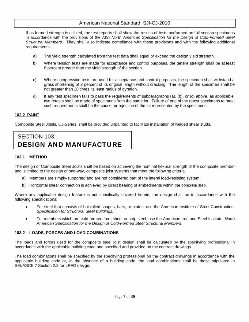
If as-formed strength is utilized, the test reports shall show the results of tests performed on full section specimens in accordance with the provisions of the AISI North American Specification for the Design of Cold-Formed Steel Structural Members. They shall also indicate compliance with these provisions and with the following additional requirements:
a) The yield strength calculated from the test data shall equal or exceed the design yield strength.
b) Where tension tests are made for acceptance and control purposes, the tensile strength shall be at least 8 percent greater than the yield strength of the section.
c) Where compression tests are used for acceptance and control purposes, the specimen shall withstand a
gross shortening of 2 percent of its original length without cracking. The length of the specimen shall be not greater than 20 times its least radius of gyration.
d) If any test specimen fails to pass the requirements of subparagraphs (a), (b), or (c) above, as applicable, two retests shall be made of specimens from the same lot. Failure of one of the retest specimens to meet such requirements shall be the cause for rejection of the lot represented by the specimens.
102.2 PAINT Composite Steel Joists, CJ-Series, shall be provided unpainted to facilitate installation of welded shear studs. 103.1 METHOD The design of Composite Steel Joists shall be based on achieving the nominal flexural strength of the composite member and is limited to the design of one-way, composite joist systems that meet the following criteria:
a) Members are simply-supported and are not considered part of the lateral load-resisting system.
b) Horizontal shear connection is achieved by direct bearing of embedments within the concrete slab. Where any applicable design feature is not specifically covered herein, the design shall be in accordance with the following specifications:
• For steel that consists of hot-rolled shapes, bars, or plates, use the American Institute of Steel Construction, Specification for Structural Steel Buildings.
• For members which are cold-formed from sheet or strip steel, use the American Iron and Steel Institute, North American Specification for the Design of Cold-Formed Steel Structural Members.
103.2 LOADS, FORCES AND LOAD COMBINATIONS The loads and forces used for the composite steel joist design shall be calculated by the specifying professional in accordance with the applicable building code and specified and provided on the contract drawings. The load combinations shall be specified by the specifying professional on the contract drawings in accordance with the applicable building code or, in the absence of a building code, the load combinations shall be those stipulated in SEI/ASCE 7 Section 2.3 for LRFD design.
SECTION 103. DESIGN AND MANUFACTURE

American National Standard SJI-CJ-2010
Page 8 of 30
At a minimum, the required stress shall be computed for the factored loads based on the factors and load combinations as follows:
(a) Non-composite
1.4Dc (103.2-1)
1.2Dc + 1.6Lc (103.2-2)
Where:
Dc = construction dead load due to weight of the joist, the decking, and the fresh concrete, lb/ft.2 (kPa)
Lc = construction live load due to the work crews and the construction equipment, lb/ft.2 (kPa) (b) Composite
1.4D (103.2-3)
1.2D + 1.6 (L, or Lr, or S, or R) (103.2-4)
Where:
D = dead load due to the weight of the structural elements and the permanent features of the structure, lb/ft.2 (kPa)
L = live load due to occupancy and movable equipment, lb/ft.2 (kPa)
Lr = roof live load, when composite joists are utilized in roofs, lb/ft.2 (kPa)
S = snow load, when composite joists are utilized in roofs, lb/ft.2 (kPa)
R = load due to initial rainwater or ice exclusive of the ponding contribution, when composite joists are utilized in roofs, lb/ft.2 (kPa)
103.3 NOMINAL STRESSES Joists shall have their components so proportioned that the required stresses, fu, shall not exceed φFn where:
fu = required stress computed for the factored loads based on the factors and load combinations, ksi (MPa)
combinations, ksi (MPa)
φ = resistance factor
Fn = nominal stress, ksi (MPa)
φFn = design stress, ksi (MPa)
Fy = specified minimum yield stress, ksi (MPa)
E = modulus of elasticity of steel, ksi (MPa) For Chords: The calculation of design stress shall be based on a yield strength, Fy, of the material used in manufacturing equal to 50 ksi (345 MPa).
For all other joist elements: The calculation of design stress shall be based on a yield strength, Fy, of the material used in manufacturing, but shall not be less than 36 ksi (250 MPa) or greater than 50 ksi (345 MPa).
Note: Yield strengths greater than 50 ksi shall not be used for the design of any joist members.

American National Standard SJI-CJ-2010
Page 9 of 30
(a) Tension: φt = 0.90
Fn = Fy (103.3-1) φFn = φtFy (103.3-2)
(b) Compression: φc = 0.90
crn FF = (103.3-3)
crcn FF φ=φ (103.3-4)
For members with
yFQE4.71r
K ≤
y
FQF
cr F658.0QF ey
=
(103.3-5)
For members with
yQFE4.71r
K >
Fcr = 0.877Fe (103.3-6) Where:
Fe = elastic buckling stress determined in accordance with Equation 103.3-7.
2
2
e
rK
EF
π=
(103.3-7)
In the above equations, is taken as the distance in inches (millimeters) between panel points for the chord members and web members, and r is the corresponding least radius of gyration of the member or any component thereof. E is equal to 29,000 ksi (200,000 MPa).
For hot-rolled sections and cold formed angles, Q is the full reduction factor for slender compression members as defined in the AISC Specification for Structural Steel Buildings.except that when the first primary compression web member is a crimped-end angle member, whether hot-rolled or cold formed:.
Q = [5.25/(w/t)] + t ≤ 1.0 (103.3-8)
Where: w = angle leg length, inches t = angle leg thickness, inches
or,
Q = [5.25/(w/t)] + (t/25.4) ≤ 1.0 (103.3-9)
Where: w = angle leg length, mm t = angle leg thickness, mm
For all other cold-formed sections the method of calculating the nominal compressive strength is given in the AISI, North American Specification for the Design of Cold-Formed Steel Structural Members.
American National Standard SJI-CJ-2010
Page 10 of 30
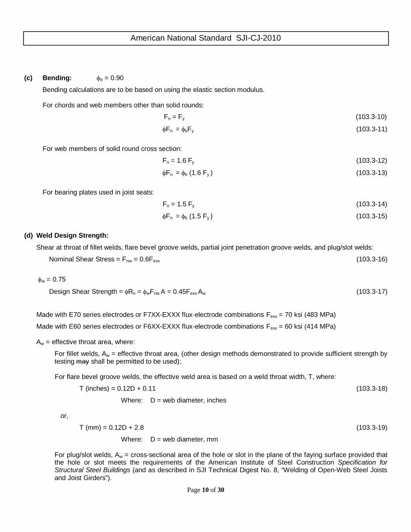
(c) Bending: φb = 0.90
Bending calculations are to be based on using the elastic section modulus.
For chords and web members other than solid rounds:
Fn = Fy (103.3-10)
φFn = φbFy (103.3-11)
For web members of solid round cross section:
Fn = 1.6 Fy (103.3-12)
φFn = φb (1.6 Fy ) (103.3-13)
For bearing plates used in joist seats:
Fn = 1.5 Fy (103.3-14)
φFn = φb (1.5 Fy ) (103.3-15)
(d) Weld Design Strength:
Shear at throat of fillet welds, flare bevel groove welds, partial joint penetration groove welds, and plug/slot welds:
Nominal Shear Stress = Fnw = 0.6Fexx (103.3-16)
φw = 0.75
Design Shear Strength = φRn = φwFnw A = 0.45Fexx Aw (103.3-17)
Made with E70 series electrodes or F7XX-EXXX flux-electrode combinations Fexx = 70 ksi (483 MPa)
Made with E60 series electrodes or F6XX-EXXX flux-electrode combinations Fexx = 60 ksi (414 MPa)
Aw = effective throat area, where:
For fillet welds, Aw = effective throat area, (other design methods demonstrated to provide sufficient strength by testing may shall be permitted to be used);
For flare bevel groove welds, the effective weld area is based on a weld throat width, T, where:
T (inches) = 0.12D + 0.11 (103.3-18)
Where: D = web diameter, inches
or,
T (mm) = 0.12D + 2.8 (103.3-19)
Where: D = web diameter, mm
For plug/slot welds, Aw = cross-sectional area of the hole or slot in the plane of the faying surface provided that the hole or slot meets the requirements of the American Institute of Steel Construction Specification for Structural Steel Buildings (and as described in SJI Technical Digest No. 8, “Welding of Open-Web Steel Joists and Joist Girders”).
American National Standard SJI-CJ-2010
Page 11 of 30
Strength of resistance welds and complete-joint-penetration groove or butt welds in tension or compression (only when the stress is normal to the weld axis) is equal to the base metal strength:
φt = φc =0.90
Design Stress = 0.90 Fy (103.3-20) 103.4 MAXIMUM SLENDERNESS RATIOS The slenderness ratios, 1.0/r and 1.0s /r of members as a whole or any component part shall not exceed the values given in Table 103.4-1, Parts A. The effective slenderness ratio, k/r to be used in calculating the nominal stresses, Fcr and F’e, is the largest value as determined from Table 103.4-1, Parts B and C. In compression members when fillers or ties are used, they shall be spaced so that the s/rz ratio of each component does not exceed the governing /r ratio of the member as a whole. The terms used in Table 103.4-1 are defined as follows:
= length center-to-center of panel points, except = 36 inches (914 mm) for calculating /ry of top chord member, in. (mm).
s = maximum length center-to-center between panel point and filler (tie), or between adjacent fillers (ties), in. (mm).
rx = member radius of gyration in the plane of the joist, in. (mm).
ry = member radius of gyration out of the plane of the joist, in. (mm).
rz = least radius of gyration of a member component, in. (mm). Compression web members are those web members subject to compressive axial loads under gravity loading. Tension web members are those web members subject to tension axial loads under gravity loading, and which may be subject to compressive axial loads under alternate loading conditions, such as net uplift. For top chords, the end panel(s) are the panels between the bearing seat and the first primary interior panel point comprised of at least two intersecting web members.
American National Standard SJI-CJ-2010
Page 12 of 30
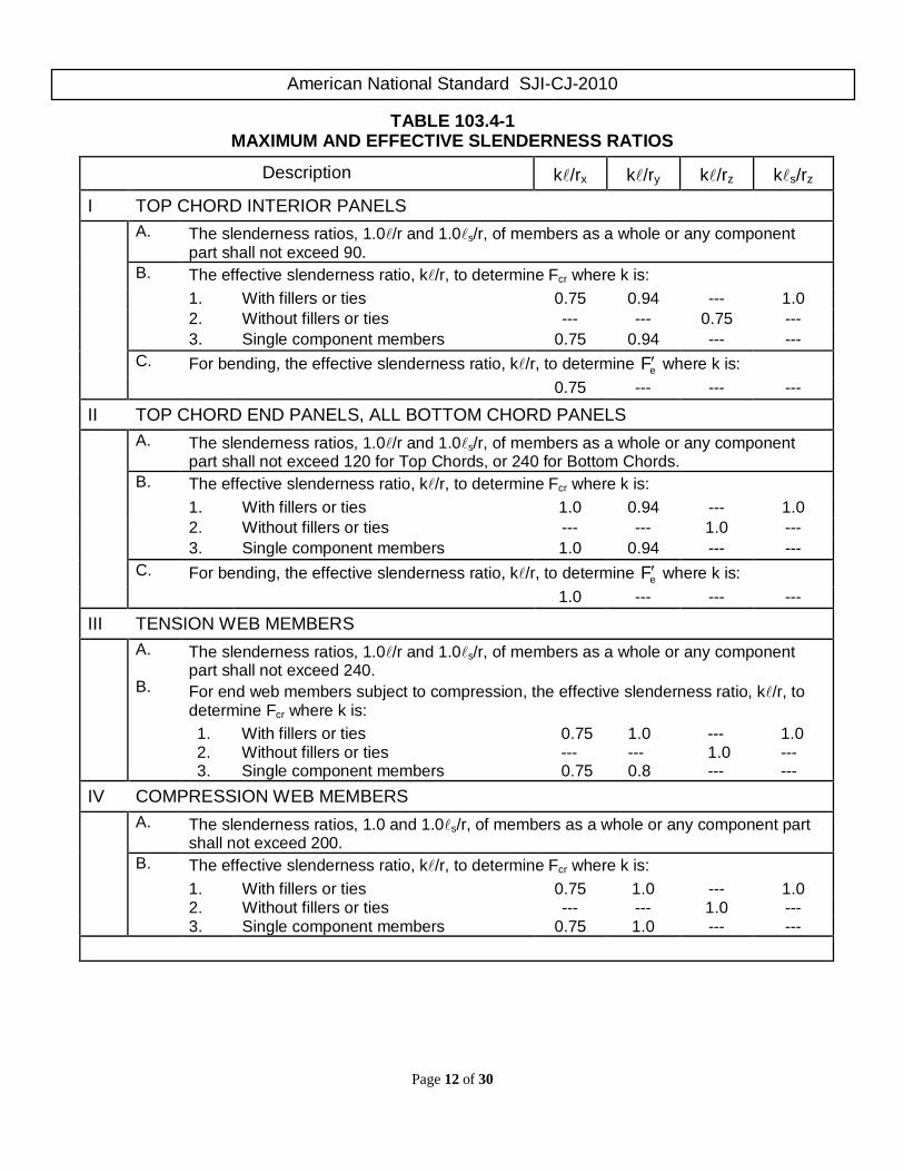
TABLE 103.4-1 MAXIMUM AND EFFECTIVE SLENDERNESS RATIOS
Description k/rx k/ry k/rz ks/rz
I TOP CHORD INTERIOR PANELS A. The slenderness ratios, 1.0/r and 1.0s/r, of members as a whole or any component
part shall not exceed 90. B. The effective slenderness ratio, k/r, to determine Fcr where k is: 1. With fillers or ties 0.75 0.94 --- 1.0 2. Without fillers or ties --- --- 0.75 --- 3. Single component members 0.75 0.94 --- --- C. For bending, the effective slenderness ratio, k/r, to determine eF′ where k is: 0.75 --- --- ---
II TOP CHORD END PANELS, ALL BOTTOM CHORD PANELS A. The slenderness ratios, 1.0/r and 1.0s/r, of members as a whole or any component
part shall not exceed 120 for Top Chords, or 240 for Bottom Chords. B. The effective slenderness ratio, k/r, to determine Fcr where k is: 1. With fillers or ties 1.0 0.94 --- 1.0 2. Without fillers or ties --- --- 1.0 --- 3. Single component members 1.0 0.94 --- --- C. For bending, the effective slenderness ratio, k/r, to determine eF′ where k is: 1.0 --- --- ---
III TENSION WEB MEMBERS A.
B.
The slenderness ratios, 1.0/r and 1.0s/r, of members as a whole or any component part shall not exceed 240. For end web members subject to compression, the effective slenderness ratio, k/r, to determine Fcr where k is: 1. With fillers or ties 0.75 1.0 --- 1.0 2. Without fillers or ties --- --- 1.0 --- 3. Single component members 0.75 0.8 --- ---
IV COMPRESSION WEB MEMBERS A. The slenderness ratios, 1.0 and 1.0s/r, of members as a whole or any component part
shall not exceed 200. B. The effective slenderness ratio, k/r, to determine Fcr where k is: 1. With fillers or ties 0.75 1.0 --- 1.0 2. Without fillers or ties --- --- 1.0 --- 3. Single component members 0.75 1.0 --- ---
American National Standard SJI-CJ-2010
Page 13 of 30
103.5 MEMBERS (a) Chords
(1) Non-composite Design
The bottom chord shall be designed as an axially loaded tension member.
The top chord shall resist the construction loads, at which time the joist is behaving non-compositely. An analysis shall be made using an effective depth of the joist to determine the member forces due to construction loads. The effective depth for a non-composite joist shall be considered the vertical distance between the centroids of the top and bottom chord members.
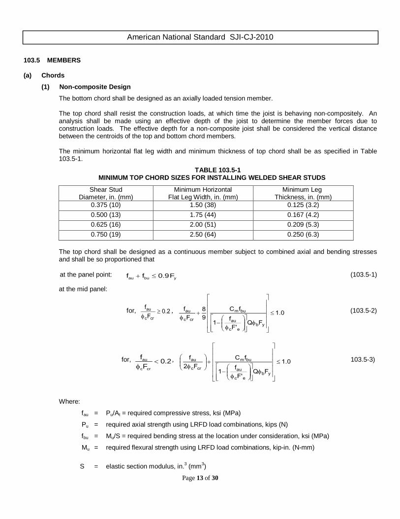
The minimum horizontal flat leg width and minimum thickness of top chord shall be as specified in Table 103.5-1.
TABLE 103.5-1 MINIMUM TOP CHORD SIZES FOR INSTALLING WELDED SHEAR STUDS
Shear Stud Diameter, in. (mm)
Minimum Horizontal Flat Leg Width, in. (mm)
Minimum Leg Thickness, in. (mm)
0.375 (10) 1.50 (38) 0.125 (3.2) 0.500 (13) 1.75 (44) 0.167 (4.2) 0.625 (16) 2.00 (51) 0.209 (5.3) 0.750 (19) 2.50 (64) 0.250 (6.3)
The top chord shall be designed as a continuous member subject to combined axial and bending stresses and shall be so proportioned that
at the panel point:
ybuau F9.0ff ≤+ (103.5-1)
at the mid panel:
for, 2.0F
fcrc
au ≥φ
, 1.0FQ
F'f1
fC98
Ff
ybec
au
bum
crc
au ≤
φ
φ
−
+φ
(103.5-2)
for, 2.0F
fcrc
au <φ
, 1.0FQ
F'f1
fCF2
f
ybec
au
bum
crc
au ≤
φ
φ
−
+
φ
103.5-3)
Where:
fau = Pu/At = required compressive stress, ksi (MPa)
Pu = required axial strength using LRFD load combinations, kips (N)
fbu = Mu/S = required bending stress at the location under consideration, ksi (MPa)
Mu = required flexural strength using LRFD load combinations, kip-in. (N-mm)
S = elastic section modulus, in.3 (mm3)
American National Standard SJI-CJ-2010
Page 14 of 30
Fcr = nominal axial compressive stress in ksi (MPa) based on /r as defined in Section 103.4
Cm = ecau Ff3.01 ′φ− for end panels
Cm = ecau Ff4.01 ′φ− for interior panels
Fy = specified minimum yield strength, ksi (MPa)
F’e = ( )2
2
/ xrKE
π , ksi (MPa)
= chord panel length per Section 103.4, in. (mm)
rx radius of gyration about the axis of bending, in. (mm)
Q = form factor defined in Section 103.3
At = area of the top chord, in.2, (mm2)
The top chord shall be considered as stayed laterally by the floor provided the requirements of Section 104.9(d) of these specifications are met.
The top chord and bottom chord shall be designed such that at each joint:
fvmod ≤ φvfn (LRFD, φ = 1.00) (103.5-4)
Where:
fn = nominal shear stress = 0.6Fy, ksi (MPa) ft = axial stress = P/A, ksi (MPa) fv = shear stress = V/bt, ksi (MPa) fvmod = modified shear stress = ( )( ) 2/12
v2t2
1 f4f + b = length of vertical part(s) of cross section, in. (mm) t = thickness of vertical part(s) of cross section, in. (mm)
It shall not be necessary to design the top chord and bottom chord for the modified shear stress when a round bar web member is continuous through a joint. The minimum required shear of section 103.5(b) (25 percent of the end reaction) shall not be required when evaluating Equation 103.5-4.
(2) Composite Design
The distance between the centroid of the tension bottom chord and the centroid of the concrete compression block, de, shall be computed using a concrete stress of 0.85f ′c and an effective concrete width, be, taken as the sum of the effective widths for each side of the joist centerline, each of which shall be the lowest value of the following:
1. one-eighth of the joist span, center-to-center of supports;
2. one-half the distance to the center-line of the adjacent joist;
3. the distance to the edge of the slab.

American National Standard SJI-CJ-2010
Page 15 of 30
A = Mn /(0.85 f’c be de) ≤ tc, in. (mm) (103.5-5)
de = dj – ybc + hdeck + tc – a/2, in. (mm) (103.5-6)
Where:
A = depth of concrete compressive stress block, in. (mm)
be = effective width of concrete slab over the joist, in. (mm)
dj = steel joist depth, in. (mm)
f c = specified minimum 28 day concrete compressive strength, ksi (MPa)
hdeck = height of metal deck, in. (mm)
Mn = nominal moment capacity of the composite joist, kip-in. (N-mm)
tc = thickness of concrete slab above the steel deck, in. (mm)
ybc = vertical distance to centroidal axis of bottom chord measured from the bottom of the bottom chord, in. (mm)
When the metal deck ribs are perpendicular to the steel joists, the concrete below the top of the metal deck shall be neglected when determining section properties and in calculating the concrete compressive block.
The contribution of the steel joist top chord to the moment capacity of the composite system shall be ignored. The first top chord end panel member shall be designed for the full factored load requirements as a non-composite member per Section 103.5(a)(1).
nu MM φ≤ (103.5-7)
φMn = minimum design flexural strength of composite section as determined from Equations 103.5-8,
103.5-9, 103.5-10, and 103.5-11, kip-in. (N-mm)
Mu = required flexural strength determined from applied factored loads, kip-in. (N-mm)
The design flexural strength of the composite section, φMn, shall be computed as the lowest value of the following limit states:
a) Bottom Chord Tensile Yielding: 90.0t =φ
eybtn dFAM φ=φ (103.5-8)
b) Bottom Chord Tensile Rupture: 75.0tr =φ
euntrn dFAM φ=φ (103.5-9)
c) Concrete Crushing: 85.0cc =φ
ececccn dtb'f85.0M φ=φ (103.5-10)
d) Shear Connector Strength: 90.0stud =φ
eybtenstudn dFA50.0dNQM φ≥φ=φ (103.5-11)
American National Standard SJI-CJ-2010
Page 16 of 30
Where:
Ab = cross-sectional area of steel joist bottom chord, in.2 (mm2)
An = net cross-sectional area of the steel joist bottom chord, in.2 (mm2)
be = effective width of concrete slab over the joist, in. (mm)
de = vertical distance from the centroid of steel joist bottom chord to the centroid of resistance of the concrete in compression, in.(mm)
Fu = tensile strength of the steel joist bottom chord, ksi (MPa)
Fy = specified minimum yield stress of steel joist bottom chord, ksi (MPa)
N = number of shear studs between the point of maximum moment and zero moment
tc = minimum thickness of the concrete slab above the top of the metal deck, in. (mm) (b) Webs
Vertical shears to be used in the design of the web members shall be determined from the controlling load combination from Section 103.2(b), but such vertical shears shall not be less than the following:
i. 25% of the factored end reaction.
ii. Tension web members controlled by (i) shall be designed for a compressive force resulting from a factored shear value of:
8L)w6.1(V L
minc = (103.5-12)
Where:
wL = non-factored live load due to occupancy and moveable equipment, plf (kN/m)
L = design length for the composite joist as defined in Table 104.2-1, Definition of Span, ft. (m) where design length = Span – 0.33 ft. (Span – 102 mm)
Vc min = minimum factored compressive design shear in tension web members, lb (kN)
Interior vertical web members used in modified Warren type web systems shall be designed to resist the gravity loads supported by the member plus 2.0 percent of the composite bottom chord axial force.
Maximum slenderness ratios shall be in accordance with Sections III and IV of Table 103.4-1.
(c) Chord Configuration
Composite joists shall have parallel chords. (d) Eccentricity
Members connected at a joint shall have their centers of gravity lines meet at a point, if practical. Eccentricity on either side of the neutral axis of chord members shall be permitted to be neglected when it does not exceed the distance between the neutral axis and the back of the chord. Otherwise, provision shall be made for the stresses due to eccentricity.
Eccentricity between the intersection of the centroid of the web members and center of compression in the concrete slab shall be permitted to be neglected. Ends of joists shall be proportioned to resist bending produced by eccentricity at the support.
In those cases where a single angle compression member is attached to the outside of the stem of a tee or double angle chord, due consideration shall be given to eccentricity.
American National Standard SJI-CJ-2010
Page 17 of 30
(e) Joist Extensions
Joist extensions are defined as one of three types, top chord extensions (TCX), extended ends, or full depth cantilevers.
Design criteria for joist extensions shall be specified using one of the following methods:
(1) A joist extension shall be designed for the load based on the design length and designation of the specified composite steel joist. In the absence of other design information, the joist manufacturer shall design the joist extension for this loading as a default.
(2) A loading diagram shall be provided for the joist extension. The diagram shall include the magnitude and
location of the loads to be supported, as well as the appropriate load combinations.
Any deflection requirements or limits due to the accompanying loads and load combinations on the joist extension shall be provided by the specifying professional, regardless of the method used to specify the extension. Unless otherwise specified, the joist manufacturer shall check the extension for the specified deflection limit under uniform live load acting simultaneously on both the joist base span and the extension.
The joist manufacturer shall consider the effects of joist extension loading on the base span of the joist. This includes carrying the design bending moment due to the loading on the extension into the top chord end panel(s), and the effect on the overall joist chord and web axial forces. The joist extension shall support all end loads without relying on any composite action.
Bracing of joist extensions shall be clearly indicated on the structural drawings.
Design of concrete reinforcing steel in the negative moment region shall be the responsibility of the specifying professional.
(f) Joist Bearing Depths
The joist bearing depths shall range from 2 1/2 inches (64 mm) to 7 1/2 inches (191 mm). 103.6 CONNECTIONS (a) Methods
Joint connections and splices shall be made by attaching the members to one another by arc or resistance welding or other accredited methods.
(1) Welded Connections
a) Selected welds shall be inspected visually by the manufacturer. Prior to this inspection, weld slag shall be removed.
b) Cracks are not acceptable and shall be repaired.
c) Thorough fusion shall exist between layers of weld metal and base metal for the required design length of the weld; such fusion shall be verified by visual inspection.
d) Unfilled weld craters shall not be included in the design length of the weld.
e) Undercut shall not exceed 1/16 inch (2 mm) for welds oriented parallel to the principal stress.
f) The sum of surface (piping) porosity diameters shall not exceed 1/16 inch (2 mm) in any 1 inch (25 mm) of design weld length.
g) Weld splatter is acceptable.
American National Standard SJI-CJ-2010
Page 18 of 30
(2) Welded Connections for Crimped-End Angle Web Members
The connection of each end of a crimped angle web member to each side of the chord shall consist of a weld group made of more than a single line of weld. The design weld length shall include, at minimum, an end return of two times the nominal weld size.
(3) Welding Program
Manufacturers shall have a program for establishing weld procedures and operator qualification and for weld sampling and testing. (See Steel Joist Institute Technical Digest 8 - Welding of Open Web Steel Joists and Joist Girders.)
(4) Weld inspection by Outside Agencies (See Section 104.13 of this specification).
The agency shall arrange for visual inspection to determine that welds meet the acceptance standards of Section 103.6(a)(1) above. Ultrasonic, X-Ray, and magnetic particle testing are inappropriate for joists due to the configurations of the components and welds.
(b) Strength
(1) Joint Connections - Joint connections shall develop the maximum force due to any of the design loads, but not less than 50 percent of the nominal strength of the member in tension or compression, whichever force is the controlling factor in the selection of the member.
(2) Shop Splices - Shop splices shall be permitted to occur at any point in chord or web members. Splices shall
be designed for the member force, but not less than 50 percent of the nominal member strength. All component parts comprising the cross section of the chord or web member (including reinforcing plates, rods, etc….) at the point of the splice, shall develop an ultimate tensile force of at least 1.2 times the product of the yield strength and the full design area of the chord or web. The “full design area” is the minimum required area such that the required stress will be less than the design stress.
(c) Field Splices
Field splices shall be designed by the manufacturer and shall be permitted to be either bolted or welded. Splices shall be designed for the member force, but not less than 50 percent of the nominal member strength.
(d) Shear Studs
Shear studs, after installation, shall extend not less than 1 1/2 in. (38 mm) above the top of the steel deck and there shall be at least 1/2 in. (13 mm) of concrete cover above the top of the installed studs.
For studs in 1.5 in. (38 mm), 2 in. (51 mm), or 3 in. (76 mm) deep decks with 7.2td chord topstud ≤ :
[ ]studustudgpccstudn FARR,EfA5.0MinQ ′= (kips) (103.6-1)
( )[ ]1000FARR,EfA5.0MinQ studustudgpccstudn ′= (kN) (103.6-2)
For studs in 1.5 in. (38 mm), 2 in. (51 mm), or 3 in. (76 mm) deep decks with 0.3td7.2 chord topstud ≤< :
( )kips7.2td5.1FARR,EfA5.0MinQ
chordtop
studstudustudgpccstudn
−−′= (103.6-3)

American National Standard SJI-CJ-2010
Page 19 of 30
( ) )kN(7.2td67.61000FARR,EfA5.0MinQ
chordtop
studstudustudgpccstudn
−−′= (103.6-
4)
Where:
Astud = cross–sectional area of shear stud, in.2 (mm2)
dstud = diameter of shear stud, in. (mm)
Ec = modulus of elasticity of the concrete, ksi (MPa)
f ’c = specified minimum 28 day concrete compressive strength, ksi (MPa)
Fu stud = minimum tensile strength of stud, 65 ksi (450 MPa)
Qn = shear capacity of a single shear stud, kips (kN)
Rp = shear stud coefficient from Table 103.6-1
Rg = 1.00 for one stud per rib or staggered position studs = 0.85 for two studs per rib side-by-side = 0.70 for three studs per rib side-by-side
ttop chord = thickness of top chord horizontal leg or flange, in. (mm)
TABLE 103.6-1 VALUES FOR Rp
Deck Height Wr @ mid-height
3/8 in. (10 mm)
Dia. Stud
1/2 in. (13 mm)
Dia. Stud
5/8 in. (16 mm)
Dia. Stud
3/4 in. (19 mm)
Dia. Stud
1 in. (25 mm) 1.9 in. (48 mm) 0.55 0.55 0.50 0.45
1.5 in. (38 mm) 2.1 in. (53 mm) 0.55 0.50 0.45 0.40
1.5 in. (38 mm) Inverted 3.9 in. (99 mm) 0.85 0.60 0.60 0.60
2 in. (51 mm) 6 in. (152 mm) --- 0.55 0.50 0.45
3 in. (76 mm) 6 in. (152 mm) --- 0.50 0.50 0.50
Notes: 1) Wr @ mid-height = Average deck rib width of deck rib containing the shear stud. 2) The deck is assumed to be oriented perpendicular to the joists.
103.7 CAMBER CJ-Series joists shall be cambered. The approximate camber shall be based on the deflection associated with 100% of the non-composite unfactored dead load plus any additional loads defined by the specifying professional. 103.8 VERIFICATION OF DESIGN AND MANUFACTURE (a) Design Calculations
Companies manufacturing any CJ-Series Joists shall submit design data to the Steel Joist Institute (or an independent agency approved by the Steel Joist Institute) for verification of compliance with the SJI Specifications.

American National Standard SJI-CJ-2010
Page 20 of 30
(b) In-Plant Inspections
Each manufacturer shall verify his ability to manufacture CJ-Series Joists through periodic In-Plant Inspections. Inspections shall be performed by an independent agency approved by the Steel Joist Institute. The frequency, manner of inspection and manner of reporting shall be determined by the Steel Joist Institute. The Plant inspections are not a guarantee of the quality of any specific joists; this responsibility lies fully and solely with the individual manufacturer.
104.1 USAGE The specifications shall apply to any type of structure where floor and roof decks are to be supported directly by Composite Steel Joists installed as hereinafter specified. Joists used other than for simple spans as prescribed in Section 103.1 shall be investigated and modified as necessary by the specifying professional to limit the unit stresses to those listed in Section 103.3. Design for large openings that interrupt truss action is beyond the scope of this specification. CAUTION: If a rigid connection of the bottom chord is to be made to the column or other support, it shall be made only after the application of the non-composite dead loads. The joist is no longer simply-supported and the system shall be investigated for continuous frame action by the specifying professional. The designed detail of a rigid type connection and moment plates shall be shown on the structural drawings by the specifying professional. The moment plates shall be furnished by other than the joist manufacturer. 104.2 SPAN The span of a standard SJI composite joist shall be from 12 to 30 times the depth of the steel joist. The term “Span” is defined in Table 104.2-1, Definition of Span. 104.3 DEPTH The depth of the composite joist shall be the vertical distance from the top of the steel top chord to the bottom of the bottom chord. 104.4 END SUPPORTS
(a) Masonry and Concrete
CJ-Series Joists supported by masonry or concrete shall bear on steel bearing plates and shall be designed as steel bearing. Due consideration of the end reactions and all other vertical and lateral forces shall be taken by the specifying professional in the design of the steel bearing plate and the masonry or concrete. The ends of CJ-Series Joists shall extend over the masonry or concrete support as shown below and be anchored to a steel bearing plate. This steel bearing plate shall be located no more than 1/2 inch (13 mm) from the face of the wall. The distance over the wall that the composite joist shall bear, width of the steel bearing plate and anchorage of the CJ-Series Joists shall be as defined below:
For 2 1/2” ≤ Seat Depth < 5”:
• The ends of CJ-Series Joists shall extend a distance of not less than 4 inches (102 mm) over the masonry or concrete support and be anchored to the steel bearing plate.
• The width of the plate perpendicular to the span of the Composite Steel Joist shall be not less than 6 inches (152 mm).
• The Composite Steel Joists shall bear a minimum of 2 1/2 inches (64 mm) on the steel bearing plate.
SECTION 104. APPLICATION

American National Standard SJI-CJ-2010
Page 21 of 30
For Seat Depth ≥ 5”:
• The ends of CJ-Series Joists shall extend a distance of not less than 6 inches (152 mm) over the masonry or concrete support and be anchored to the steel bearing plate.
• The width of the plate perpendicular to the span of the Composite Steel Joist shall be not less than 9 inches (229 mm).
• The Composite Steel Joists shall bear a minimum of 4 inches (102 mm) on the steel bearing plate.
The steel bearing plate is to be designed by the specifying professional and shall be furnished by other than the joist manufacturer.
Where it is deemed necessary to bear less than the dimensions listed above over the masonry or concrete support, special consideration is to be given to the design of the steel bearing plate and the masonry or concrete by the specifying professional. The joist shall meet the minimum bearing requirement on the steel bearing plate.
(b) Steel
Due consideration of the end reactions and all other vertical and lateral forces shall be taken by the specifying professional in the design of the steel support.
For 2 1/2” ≤ Seat Depth < 5”:
The ends of CJ-Series Joists shall extend a distance of not less than 2 1/2 inches (64 mm) over the steel supports.
For Seat Depth ≥ 5”:
The ends of CJ-Series Joists shall extend a distance of not less than 4 inches (102 mm) over the steel supports.
Where deemed necessary to butt opposite joists over a narrow steel support with bearing less than that noted above, special ends shall be specified, and such ends shall have positive attachment to the support, either by bolting or welding.
104.5 BRIDGING Top and bottom chord bridging is required and shall consist of one or both of the following types: (a) Horizontal
Horizontal bridging lines shall consist of continuous horizontal steel members. The /r ratio of the bridging member shall not exceed 300, where is the distance in inches (millimeters) between attachments and r is the least radius of gyration of the bridging member.
(b) Diagonal
Diagonal bridging lines shall consist of cross-bracing with a /r ratio of not more than 200, where is the distance in inches (millimeters) between connections and r is the least radius of gyration of the bracing member. Where cross-bracing members are connected at their point of intersection, the distance shall be taken as the distance in inches (millimeters) between connections at the point of intersection of the bridging members and the connections to the chords of the joists.
American National Standard SJI-CJ-2010
Page 22 of 30
(c) Bridging Lines
For spans up through 60 feet (18.3 meters), welded horizontal bridging shall be permitted to be used except where the row of bridging nearest the center is required to be bolted diagonal bridging as indicated on the joist manufacturer’s joist placement plans. When the span of the composite steel joist is over 60 feet (18.3 meters), but not greater than 100 feet (30.5 meters), hoisting cables shall not be released until the two rows of bridging nearest the third points are completely installed. When the span exceeds 100 feet (30.5 meters) hoisting cables shall not be released until all rows of bridging are completely installed. For spans over 60 feet (18.3 meters) all rows of bridging shall be diagonal bridging with bolted connections at the chords and intersections.
(d) Spacing
Bridging shall be properly spaced and anchored to support the decking and the employees prior to the attachment of the deck to the top chord. The maximum spacing of lines of bridging, brmax shall be the lesser of,
y
jjbrmax r
Ld
40d0.67100
++= , in. (104.5-1a)
yj
jbrmax rLd
0.48d0.026100
++= , mm (104.5-1b)
Or,
ybrmax r170= (104.5-2)
Where:
dj is the steel joist depth, in. (mm) L is the design length for the composite joist, ft. (m) ry is the out-of-plane radius of gyration of the top chord, in. (mm)
The number of rows of bottom chord bridging shall not be less than the number of top chord rows. Rows of bottom chord bridging are permitted to be spaced independently of rows of top chord bridging.
(e) Connections
Connection of bridging to the chords of the Composite Steel Joists shall be made by positive mechanical means or by welding. Ends of all bridging lines terminating at walls, beams, or double joists boxed by diagonal bridging shall be anchored.
Connection of the horizontal and diagonal bridging to the joist chord or bridging terminus point shall be capable of resisting the nominal top chord horizontal force, Pbr given in Equation 104.5-3.
Pbr = 0.0025 n At Fconstruction , lbs (N) (104.5-3)
Where
n = 8 for horizontal bridging
n = 2 for diagonal bridging
At = cross sectional area of joist top chord, in.2 (mm2)
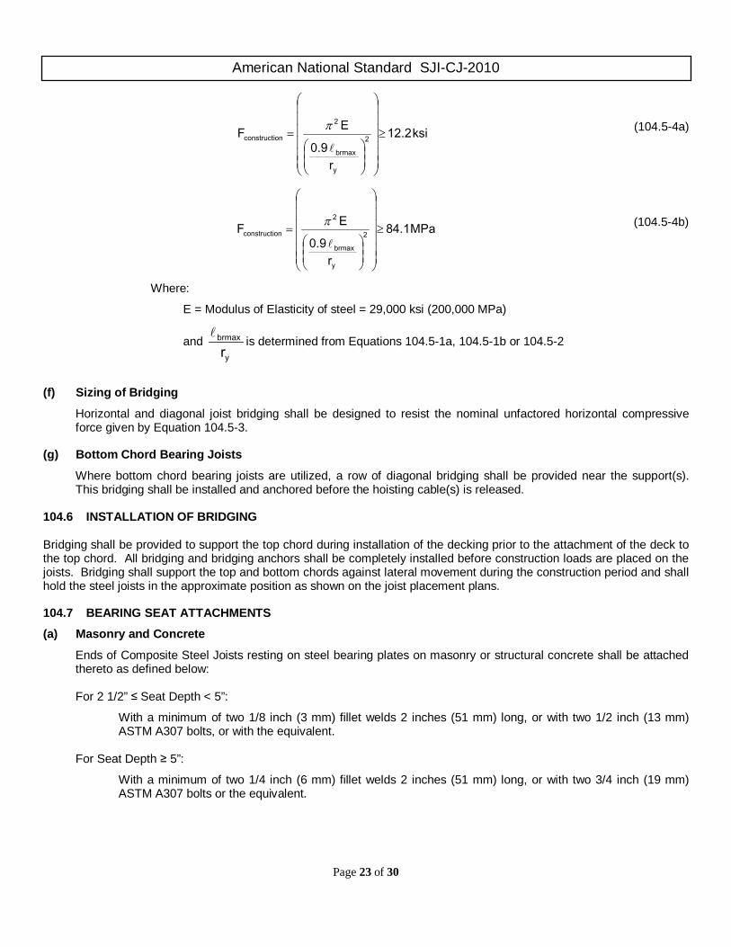
Fconstruction = assumed ultimate stress in top chord to resist construction loads
American National Standard SJI-CJ-2010
Page 23 of 30
ksi12.2
r0.9
EF 2
y
brmax
2
onconstructi ≥
=
π (104.5-4a)
MPa 84.1
r0.9
EF 2
y
brmax
2
onconstructi ≥
=
π (104.5-4b)
Where:
E = Modulus of Elasticity of steel = 29,000 ksi (200,000 MPa)
and y
brmax
r
is determined from Equations 104.5-1a, 104.5-1b or 104.5-2
(f) Sizing of Bridging
Horizontal and diagonal joist bridging shall be designed to resist the nominal unfactored horizontal compressive force given by Equation 104.5-3.
(g) Bottom Chord Bearing Joists
Where bottom chord bearing joists are utilized, a row of diagonal bridging shall be provided near the support(s). This bridging shall be installed and anchored before the hoisting cable(s) is released.
104.6 INSTALLATION OF BRIDGING Bridging shall be provided to support the top chord during installation of the decking prior to the attachment of the deck to the top chord. All bridging and bridging anchors shall be completely installed before construction loads are placed on the joists. Bridging shall support the top and bottom chords against lateral movement during the construction period and shall hold the steel joists in the approximate position as shown on the joist placement plans. 104.7 BEARING SEAT ATTACHMENTS
(a) Masonry and Concrete
Ends of Composite Steel Joists resting on steel bearing plates on masonry or structural concrete shall be attached thereto as defined below:
For 2 1/2” ≤ Seat Depth < 5”:
With a minimum of two 1/8 inch (3 mm) fillet welds 2 inches (51 mm) long, or with two 1/2 inch (13 mm) ASTM A307 bolts, or with the equivalent.
For Seat Depth ≥ 5”:
With a minimum of two 1/4 inch (6 mm) fillet welds 2 inches (51 mm) long, or with two 3/4 inch (19 mm) ASTM A307 bolts or the equivalent.

American National Standard SJI-CJ-2010
Page 24 of 30
(b) Steel
Ends of Composite Steel Joists resting on steel supports shall be attached thereto as defined below:
For 2 1/2” ≤ Seat Depth < 5”:
With a minimum of two 1/8 inch (3 mm) fillet welds 2 inches (51 mm) long, or with two 1/2 inch (13 mm) ASTM A307 bolts, or with the equivalent.
For Seat Depth ≥ 5”:
With a minimum of two 1/4 inch (6 mm) fillet welds 2 inches (51 mm) long, or with two 3/4 inch (19 mm) ASTM A307 bolts or the equivalent.
In steel frames, where columns are not framed in at least two directions with solid structural steel members, joists at column lines shall be field bolted and the joist bottom chords shall be restrained by a vertical stabilizer plate attached to the column providing lateral stability during construction. Where constructability does not allow a steel joist to be installed directly at the column, an alternate means of stabilizing the joist shall be installed on both sides near the column (OSHA 2001). When CJ-Series Joists are used to provide lateral stability to the supporting member, the final connection shall be made by welding or as designated by the specifying professional.
(c) Uplift
Where uplift forces are a design consideration, composite joists used in roof applications shall be anchored to resist such forces (Refer to Section 104.12).
104.8 JOIST SPACING Composite joists shall be spaced so that the loading on each joist does not exceed the design load. 104.9 DECKS (a) Material
Floor deck shall consist of formed steel capable of supporting the required load at the specified joist spacing. (b) Thickness
Cast-in-place slabs shall be not less than 2 inches (51 mm) thick above the deck. (c) Bearing
Slabs or decks shall bear uniformly along the top chords of the joists. (d) Attachments of the steel deck
The deck shall be attached per Steel Deck Institute requirements (ANSI/SDI C1.0-2006, Standard for Composite Steel Floor Deck and ANSI/SDI NC-2010, Standard for Noncomposite Steel Floor Deck) prior to placing construction loads on the composite joists. The spacing of the attachments along the top chord shall not exceed 36 inches (914 mm). 104.10 DEFLECTION The deflection due to the design live load shall not exceed the following:
Floors: 1/360 of span. Roofs: 1/360 of span where a plaster ceiling is attached or suspended.
1/240 of span for all other cases.

American National Standard SJI-CJ-2010
Page 25 of 30
The specifying professional shall give due consideration to the effects of deflection, both short and long term, and vibration* in the selection of composite joists. All deflection calculations shall account for the inherent flexibility of the open web configuration.
*For further reference, refer to Steel Joist Institute Technical Digest #5, “Vibration of Steel Joist-Concrete Slab Floors” and the Institute’s Computer Vibration Program.
104.11 PONDING When Composite Steel Joists are used in roofs, a ponding investigation shall be performed by the specifying professional.
* For further reference, refer to the Steel Joist Institute Technical Digest #3, “Structural Design of Steel Joist Roofs to Resist Ponding Loads” and the AISC Specification for Structural Steel Buildings.
104.12 UPLIFT When Composite Steel Joists are used in roofs, and where uplift forces due to wind are a design requirement, these forces shall be indicated on the contract drawings in terms of net uplift in pounds per square foot (kilopascals). When these forces are specified, they shall be considered in the design of the joists and/or bridging. A single line of bottom chord bridging shall be provided near the first bottom chord panel points whenever uplift due to wind forces is a design consideration.
* For further reference, refer to Steel Joist Institute Technical Digest #6, “Structural Design of Steel Joist Roofs to Resist Uplift Loads”.
104.13 INSPECTION Joists shall be inspected by the manufacturer before shipment to verify compliance of materials and workmanship with the requirements of these specifications. If the purchaser wishes an inspection of the steel joists by someone other than the manufacturer’s own inspectors, they shall be permitted to reserve the right to do so in their “Invitation to Bid” or the accompanying “Job specifications”. Arrangements shall be made with the manufacturer for such shop inspection of the joists at the manufacturing shop by the purchaser’s inspectors at purchaser’s expense.

American National Standard SJI-CJ-2010
Page 26 of 30
TABLE 104.2-1 DEFINITION OF SPAN
C L L C SPAN
SPAN L C
SPAN
BEARING LENGTH BEARING LENGTH
BEARING LENGTH BEARING LENGTH
BEARING LENGTH BEARING LENGTH
DETAIL #1
DETAIL #2
DETAIL #3
CLEAR SPAN CLEAR SPAN
DETAIL #3
DETAIL #2
SPAN
BEARING LENGTH BEARING LENGTH SEAT
DEPTH
DETAIL #1
SPAN
SPAN
BEARING LENGTH
BEARING LENGTH
C L
BEARING LENGTH
C L
BEARING LENGTH
C L
NOTES: 1) DESIGN LENGTH (ENGLISH UNITS) = SPAN - 0.33 FT. DESIGN LENGTH (METRIC UNITS) = SPAN - 102 mm
2) MINIMUM BEARING LENGTH IS A FUNCTION OF THE SEAT DEPTH. (SEE SECTION 104.4)

American National Standard SJI-CJ-2010
Page 27 of 30
When it is necessary for the erector to climb on the composite steel joists, extreme caution shall be exercised since unbridged joists exhibit some degree of instability under the erector’s weight.
* For a thorough coverage of this topic, refer to Steel Joist Institute Technical Digest #9, “Handling and Erection of Steel Joists and Joist Girders”.
(a) Erection Stability
Joist erection bridging requirements shall be determined by the joist manufacturer and indicated on the joist placement plans.
(b) Stability Requirements during Joist Erection
(1) Before an employee is allowed on the composite steel joist: BOTH ends of composite joists at columns (or composite joists designated as column joists) shall be attached to its supports. For all other composite joists a minimum of one end shall be attached before the employee is allowed on the composite joist. The attachment shall be in accordance with Section 104.7- End Anchorage.
When a bolted seat connection shall be used for erection purposes, as a minimum, the bolts shall be snug tightened. The snug tight condition shall be defined as the tightness that exists when all plies of a joint are in firm contact. This shall be attained by a few impacts of an impact wrench or the full effort of an employee using an ordinary spud wrench.
(2) On composite steel joists that do not require erection bridging as shown on the joist placement plans, only
one employee shall be allowed on the composite joist unless all bridging is installed and anchored.
(3) Where the span of the composite steel joist requires one line of bolted diagonal erection bridging nearest the mid-span of the joist, as indicated on the joist placement plans, the following shall apply:
a. Hoisting cables shall not be released until the row of bolted diagonal erection bridging is installed and anchored, unless an alternate method of stabilizing the composite steel joist has been provided; and
b. No more than one employee shall be allowed on these spans until all bridging is installed and anchored.
(4) Where the span of the Composite Steel Joist requires two lines of bolted diagonal erection bridging nearest the third points of the joist, as indicated on the joist placement plans, the following shall apply:
a. Hoisting cables shall not be released until the two rows of bolted diagonal erection bridging are installed and anchored; and
b. No more than two employees shall be allowed on these spans until all other bridging is installed and anchored.
(5) Where the span of the composite steel joist requires all lines of bridging to be bolted diagonal erection
bridging as indicated on the joist placement plans, the following shall apply:
a. Hoisting cables shall not be released until all bridging is installed and anchored; and
b. No more than two employees shall be allowed on these spans until all other bridging is installed and anchored.
SECTION 105. ERECTION STABILITY AND HANDLING*

American National Standard SJI-CJ-2010
Page 28 of 30
(6) When permanent bridging terminus points can not be used during erection, additional temporary bridging
terminus points are required to provide lateral stability.
(7) In the case of bottom chord bearing joists, the ends of the composite joist shall be restrained laterally per Section 104.5(g) before releasing the hoisting cables.
(8) After the composite steel joist is straightened and plumbed, and all bridging is completely installed and
anchored, the ends of the joists shall be fully connected to the supports in accordance with Section 104.7- End Anchorage.
(c) Landing and Placing Loads
(1) Except as stated in paragraph 105(c)(3) of this section, no “construction loads” (1) shall be allowed on the Composite Steel Joists until all bridging is installed and anchored, and all joist bearing ends are attached. “construction loads” (for joist erection) means any load other than the weight of the employee(s), the joists, and the bridging bundle(s).
(2) During the construction period, loads placed on the Composite Steel Joists shall be distributed so as not to exceed the non-composite capacity of the composite steel joists.
(3) The weight of a bundle of joist bridging shall not exceed a total of 1000 pounds (454 kilograms). The bundle of joist bridging shall be placed on a minimum of 3 steel joists that are secured at one end. The edge of the bridging bundle shall be positioned within 1 foot (0.30 m) of the secured end.
(4) No bundle of deck shall be placed on Composite Steel Joists until all bridging has been installed and
anchored and all composite steel joist bearing ends attached, unless the following conditions are met:
a. The contractor has first determined from a “qualified person” (2) and documented in a site specific erection plan that the structure or portion of structure is capable of supporting the load. A “qualified person” means one who, by possession of a recognized degree, certificate, or professional standing, or who by extensive knowledge, training, and experience, has successfully demonstrated the ability to solve or resolve problems relating to the subject mater, the work, or the project;
b. The bundle of decking is placed on a minimum of 3 composite steel joists;
c. The composite steel joists supporting the bundle of decking are attached at both ends;
d. At least one row of bridging is installed and anchored;
e. The total weight of the decking does not exceed 4000 pounds (1816 kilograms);
f. The edge of the bundle of decking shall be placed within 1 foot (0.30 meter) of the bearing surface of the composite steel joist end.
(5) The edge of any construction load shall be placed within 1 foot (0.30 meter) of the bearing surface of the
composite steel joist end. (d) Field Welding
(1) All field welding shall be performed in accordance with contract documents. Field welding shall not damage the composite joists.
(2) On cold-formed members whose yield strength has been attained by cold working, and whose as-formed
strength is used in the design, the total length of weld at any one point shall not exceed 50 percent of the overall developed width of the cold-formed section.
American National Standard SJI-CJ-2010
Page 29 of 30
(e) Handling
Particular attention shall be paid to the erection of Composite Steel Joists. Care shall be exercised at all times to avoid damage to the composite joists and accessories. Hoisting cables shall be attached at panel point locations and those locations shall be selected to minimize erection stresses. Each Composite Steel Joist shall be adequately braced laterally before any loads are applied. If lateral support is provided by the bridging, the bridging lines as defined in Section 105(b), paragraphs (2), (3), (4) and (5), shall be anchored to prevent lateral movement.
(f) Fall Arrest Systems
Composite steel joists shall not be used as anchorage points for a fall arrest system unless written approval to do so is obtained from a “qualified person” as defined in paragraph 105(c)(3)(a).
(1) See Federal Register, Department of Labor, Occupational Safety and Health Administration (2001), 29 CFR Part 1926 Safety Standards for Steel Erection; Final Rule, §1926.757 Open Web Steel Joists - January 18, 2001, Washington, D.C. for definition of “construction load”. (2) See Federal Register, Department of Labor, Occupational Safety and Health Administration (2001), 29 CFR Part 1926 Safety Standards for Steel Erection; Final Rule, §1926.757 Open Web Steel Joists - January 18, 2001, Washington, D.C. for definition of “qualified person”. (a) Shear connectors required on each side of the point of maximum positive or negative bending moment, shall be
distributed uniformly between that point and the adjacent points of zero moment, unless otherwise specified. However the number of shear connectors placed between any concentrated load and the nearest point of zero moment shall be sufficient to develop the maximum moment required at the concentrated load point.
(b) Studs shall be alternately placed on each chord angle section for double angle top chords. When constructability does not allow this to occur, stud placement shall be limited as follows:
1. No more than three studs shall be placed consecutively on any one chord angle, and 2. No more than 60% of the total number of studs shall be placed on any one chord angle.
Studs shall have a minimum of 1/2 inch (13 mm) concrete cover over the head of each stud (see Section 103.6(d)).
(c) The minimum center-to-center spacing of stud connectors shall be six stud diameters along the longitudinal axis of the supporting composite joist, except that within the ribs of formed steel decks oriented perpendicular to the steel joists, the minimum center-to-center spacing shall be four stud diameters in any direction.
(d) The distance measured along the longitudinal axis of the joist from the free edge of the concrete slab to the first stud shall not be less than the deck height plus four stud diameters.
(e) The spacing of stud shear connectors along the length of the supporting joist shall not exceed eight times the slab depth or 36 inches (914 mm).
(f) To resist uplift, the steel deck shall be anchored to all supporting members at a spacing not to exceed 18 inches (460 mm). Such anchorage shall be provided by stud connectors, a combination of stud connectors and arc spot (puddle) welds, or other devices.
SECTION 106. SHEAR CONNECTOR PLACEMENT AND WELDING

American National Standard SJI-CJ-2010
Page 30 of 30
When a method of shear transfer is used other than headed shear studs for developing composite joist behavior, the strength of shear connectors and details of composite construction shall be established by a test program that has been submitted to and accepted by the SJI.
SECTION 107. SPECIAL CASES