Embed Size (px)
Citation preview

BC&A – 3/19/18 ADDENDUM NO. 2 SGWRF HEADWORKS AND UV DISINFECTION PROJECT PAGE 1
ADDENDUM NO. 2 TO THE CONTRACT DOCUMENTS
FOR THE CONSTRUCTION OF
SGWRF HEADWORKS AND UV DISINFECTION PROJECT
Date: March 19, 2018
To All Planholders and/or Prospective Bidders: The following changes, additions, and/or deletions are hereby made a part of the Contract Documents for the Construction of the SGWRF Headworks and UV Disinfection Project, dated February 2018 as fully and completely as if the same were fully set forth therein: TECHNICAL SPECIFICATIONS 1. Bid Documents – Public Notice
a. Change the Bid Date in the first paragraph. Bid Date will now be 2:00 p.m. MDT, April
4, 2018.
2. Bid Documents – Information for Bidders a. Change the Bid Date in the paragraph 3. Bid Date will now be 2:00 p.m. MDT, April 4,
2018. 3. Section 05 21 00 – Steel Joist Framing
a. Delete section in its entirety and replace with the attached Specification 05 21 00 – Steel
Joist Framing. 4. Section 09 90 10 - Pipeline Coatings and Linings
a. Delete paragraph 2.2.A.1 in its entirety and replace with the following paragraph 2.2.A.1.
2.2 SHOP-APPLIED, BURIED PIPE COATINGS
A. General
1. Buried steel pipe, consisting of straight lengths of pipe, shall be coated with one of the following coating systems at the Contractors option, except where noted otherwise. a. Polyethylene Tape Wrap and cement overcoat (AWWA C214 and C205) b. Plural Component Epoxy (AWWA C213 C210)
5. Section 43 27 10 – Open Screw Pumps
a. Delete section in its entirety and replace with the attached Specification 43 27 10 – Open
Screw Pumps.

BC&A – 3/19/18 ADDENDUM NO. 2 SGWRF HEADWORKS AND UV DISINFECTION PROJECT PAGE 2
DRAWINGS 1. Drawing C-02 – Partial Demolition Plan 1 – Sheet 11 of 230
a. Delete Key Note 7 in its entirety and replace with the following.
7. Remove and dispose of existing Headworks Facility in its entirety. See Section 02 41
00 for items to be salvaged to Owner.
b. Delete Key Note 25 in its entirety and replace with the following.
25. Remove and dispose of Auxiliary Pump Station in its entirety. Remove and salvage submersible pumps from Auxiliary Pump Station to Owner.
2. Drawing C-23 – YARD PIPING COORDINATES – sheet 32 of 230
c. Delete Drawing C-23 in its entirety and replace with the attached Drawing C-23.
• Manhole size changed to 5-ft diameter at identified locations.
3. Drawing C-25 – YARD PIPING PROFILE - 1 – sheet 34 of 230
a. Delete Drawing C-25 in its entirety and replace with the attached Drawing C-25.
• Manhole size changed to 5-ft diameter at identified locations.
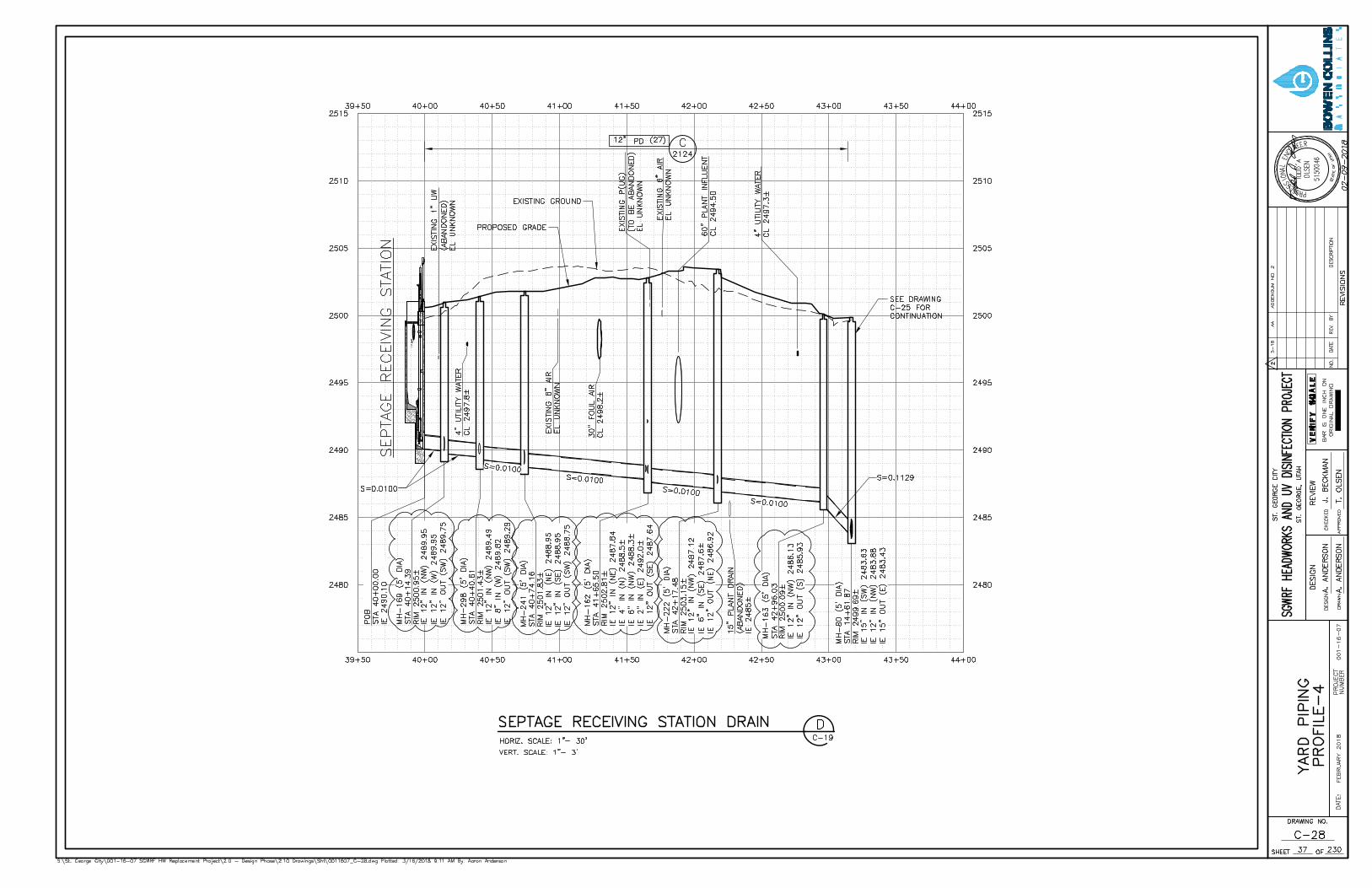
4. Drawing C-28 – YARD PIPING PROFILE 4 – sheet 37 of 230
a. Delete Drawing C-28 in its entirety and replace with the attached Drawing C-28.
• Manhole size changed to 5-ft diameter at identified locations.
CLARIFICATIONS
1. Last day for bid period questions will be March 30, 2018.
2. Question: Is the intent to demo and remove the existing headworks in its entirety, unlike the existing UV structure to remove as indicated (more or less the top portion and back fill)? Is any portion of the existing headworks to remain below grade? Response: Yes, headworks it to be removed in its entirety. See above for modification to drawing C-02.
3. Question: What couplings shall be used in the Vaults on the 60”, 48” and 42” carbon steel piping. Response: Specification 40 05 00 – Piping, General in paragraph 2.4.B.1 requires the coupling for Steel Pipe to be Victaulic Style 44 with Type D Heavy Duty Grooved Adaptor Ends.

BC&A – 3/19/18 ADDENDUM NO. 2 SGWRF HEADWORKS AND UV DISINFECTION PROJECT PAGE 3
All Bidders shall acknowledge receipt and acceptance of this Addendum No. 2 in the Bid Form. Bid Forms submitted without acknowledgment of this Addendum will be considered non-responsive. BOWEN COLLINS & ASSOCIATES __________________________________ Jeff Beckman, P.E. Project Manager END OF ADDENDUM

BC&A – 3/19/18 ADDENDUM NO. 2 SGWRF HEADWORKS AND UV DISINFECTION PROJECT PAGE 4
ATTACHMENT 1 REVISED SPECIFICATIONS

BC&A ADDENDA NO. 2 CITY OF ST. GEORGE STEEL JOISTS FRAMING SGWRF HEADWORKS AND UV DISINFECTION PROJECT PAGE 05 21 00 - 1
SECTION 05 21 00 STEEL JOISTS FRAMING
PART 1 - GENERAL
1.1 SUMMARY
A. Provide pre-engineered steel joists in accordance with Contract Documents.
1.2 RELATED SECTIONS
A. Section 03 60 00 – Grouting
B. Section 05 50 00 – Metal Fabrications
C. Section 09 90 00 – Painting and Coating
1.2 REFERENCES
D. American Institute of Steel Construction (AISC) standards, most recent editions: 1. Specifications for Structural Steel Buildings. 2. Code of Standard Practice for Steel Buildings and Bridges.
E. ASTM International (ASTM) standards, most recent editions:
ASTM A307 Standard Specification for Carbon Steel Bolts and Studs, 60,000 PSI Tensile Strength.
ASTM A325 Standard Specification for Structural Bolts, Steel, Heat Treated, 120/105 ksi Minimum Tensile Strength.
F. American Welding Society (AWS) standards, most recent editions:
D1.1 Structural Welding Code-Steel.
G. Steel Joist Institute (SJI) standards, most recent edition.
Recommended Code of Standard Practice for Steel Joists and Joist Girders.
Standard Specifications for Open Web Steel Joists, K-Series.
Standard Specifications for Longspan Steel Joists, LH-Series and Deep Longspan Steel Joists, DLH-Series.
Technical Digest #8, "Welding of Open Web Steel Joists."
H. Society for Protective Coatings (SSPC) standards, most recent edition:
SSPC-Paint 15 Steel Joist Shop Primer/Metal Building Primer.

BC&A ADDENDA NO. 2 CITY OF ST. GEORGE STEEL JOISTS FRAMING SGWRF HEADWORKS AND UV DISINFECTION PROJECT PAGE 05 21 00 - 2
1.3 SUBMITTALS
A. Submit in accordance with Section 01 33 20 – Submittal Procedures.
B. Shop drawings: 1. Detailed shop drawings showing size and layout of joist units, bridging, connections,
and accessories. Include mark, number, type, locations, and spacing of joists and bridging.
2. Provide templates or location drawings for installation of any required anchor bolts. 3. Indicate beveled end plates for joist roof pitch where required. Provide details of
bridging, method of attachment to joists, and joist end anchorage and other details required for joist installation.
4. Shop drawings shall not be reproductions of the Contract Drawings.
C. Certifications: 1. Submit evidence that joist manufacturer is a member of the Steel Joist Institute (SJI). 2. Welding certifications. 3. Capability of joist in accordance with Paragraph 2.2 B.
1.4 QUALITY ASSURANCE
A. Qualifications: 1. Fabricator: Fabricator shall be a member of the Steel Joist Institute who regularly
produces steel joists of the K-, KCS, LH-, and DLH-Series, or joist girders conforming to SJI Specifications and Load Tables and whose designs have been checked and accepted by the SJI.
2. Erector: Use erectors with a minimum of 5 years' experience installing steel joists equal in material, design, and scope to the trusses required for this Project.
3. Welders: a. Qualify welding processes, operations, and operators in accordance with AWS
D1.1 and SJI Technical Digest #8, "Welding of Open Web Steel Joists." b. Welding operators to have been qualified during the 12 month period prior
to commencement of welding. 4. Joist designer: The design professional, licensed to practice in the state of Utah,
having responsibility for the design of the joists. The joist designer shall be either an employee of the joist fabricator or a consultant.
B. Shop inspection may be required by Owner at Owner’s own expense and option. 1. Furnish ample notice to Engineer prior to the beginning of fabrication work so that
inspection may be provided. 2. Furnish all facilities for the inspection of materials and workmanship in the shop and
allow inspectors free access to the necessary parts of the Work. 3. Inspectors shall have the authority to reject materials and Work that does not meet
Specifications. 4. Inspection at the shop is intended to facilitate the Work and avoid errors, but will in
no way relieve Contractor from the responsibility for providing proper materials and workmanship under this Specification.

BC&A ADDENDA NO. 2 CITY OF ST. GEORGE STEEL JOISTS FRAMING SGWRF HEADWORKS AND UV DISINFECTION PROJECT PAGE 05 21 00 - 3
1.5 DELIVERY, STORAGE, AND HANDLING
A. Comply with Section 01 25 10 - Products, Materials, Equipment and Substitutions.
B. Deliver materials to site at such intervals to ensure uninterrupted progress of Work. Inspect the joists for damage before unloading and note any permanent bend or deformation or broken welds on the receiving documents.
C. Store materials to permit easy access for inspection and identification. Keep joist members off ground using pallets, skids, platforms, or other supports.
D. Protect steel members from corrosion and damage.
E. Store packaged materials in original unbroken package or container.
F. Do not store materials on structure in a manner that might cause distortion or damage to members or supporting structures.
G. Replace damaged shapes or members as required by Engineer.
PART 2 - PRODUCTS
2.1 MANUFACTURERS
A. Subject to compliance with the Contract Documents, the following Manufacturers are acceptable: 1. Steel joists:
a. CANAM Steel Corporation. b. CMC Joist and Deck. c. Nucor Corporation, Vulcraft Divisions d. Valley Joist, Incorporated. e. Engineer approved equal.
2.2 STEEL JOIST
A. Provide steel joists that have been designed for loadings and configurations specified on the Contract Drawings and that have been found to conform to the SJI standard specifications.
B. Special or concentrated loads: 1. Where special loadings and concentrated loads are indicated in the Contact
Documents, reinforce joist and develop details as necessary for support of such loads. 2. Submit written certification that the joist(s) have been designed, fabricated, and are
capable of supporting the loadings indicated for the span(s) shown. Written certification to be signed and sealed by a professional engineer licensed to practice in the state of Utah.
C. Design in accordance with SJI Specifications:

BC&A ADDENDA NO. 2 CITY OF ST. GEORGE STEEL JOISTS FRAMING SGWRF HEADWORKS AND UV DISINFECTION PROJECT PAGE 05 21 00 - 4
1. Joist designations indicated on the Contract Drawings are minimum requirements. Increase as required to comply with design requirements specified.
2. Whenever possible, increased joists shall have the same depth as joist indicated on Contract Drawings.
3. When necessary to increase joist depths to meet design requirements, coordinate all Project changes required due to the increased depth at no additional cost to Owner.
D. Bridging: Provide horizontal or diagonal type bridging as required by SJI specifications or as indicated on Contract Drawings for type of joist, chord size, spacing and span. 1. Supply bridging to ensure stability of structure during construction period.
E. Extended ends: Provide extended ends on joists as indicated on Contract Drawings complying with applicable SJI specifications and load tables.
F. Top chord extension: Top chord extensions shall be capable of withstanding the full uniform load of the joist plus any concentrated loads shown on the Contract Documents. The extensions shall be attached to the perimeter bracing unless shown otherwise on the Contract Drawings.
G. Bottom chord extension: Provide bottom chord extensions of sufficient strength to support ceiling construction when ceilings are shown on the Contract Documents. 1. Provide either an extended bottom chord or a separate unit of sufficient strength to
support ceiling construction. 2. Extend ends to within 1/2 inch of wall surface.
2.3 MATERIALS
A. Steel: Comply with requirements of SJI specifications.
B. Unfinished threaded fasteners: ASTM A307, Grade A, regular hexagon type, low carbon steel.
C. High-strength bolts and nuts: ASTM A325, Type I, heavy hex structural bolts, heavy hex nuts and hardened steel washers.
D. Accessories: Provide accessories required for erection of steel joists, complying with SJI specifications and Contract Drawings.
2.4 FABRICATION
A. Fabricate in accordance with SJI specifications and as follows: 1. Do not splice principal tension members. Use only full length pieces. 2. Make shop connections and splices using either arc or resistance welding. Do not
shop-bolt connections. 3. Design and fabricate for maximum deflection of 1/240 of clear span under design live
load. 4. Shop holes, field holes, and enlargement of holes will not be permitted unless
approved by Engineer. 5. Fabricate bearing ends to provide following minimum bearing unless a longer
bearing length is shown or specified.

BC&A ADDENDA NO. 2 CITY OF ST. GEORGE STEEL JOISTS FRAMING SGWRF HEADWORKS AND UV DISINFECTION PROJECT PAGE 05 21 00 - 5
Support “LH” and “DLH” Joists “K” and “KCS”
Joists Joist Girders
On Masonry or Concrete. 6 inches min 4 inches min 6 inches min
On Steel. 2-1/2 inches min 4 inches min 4 inches min
2.5 SHOP COATING
A. Limit shop coating to primer which is compatible with specified finish paints.
B. Refer to Section 09 90 00 – Painting and Coating. Coordinate shop primer, surface preparation, and coating with field applied primers and coatings where specified.
C. Provide suitable methods of handling and transporting painted steel joists to minimize damage to coating.
D. Do not coat following surfaces: 1. Surfaces adjacent to field welds and surfaces fully embedded in concrete. 2. Joists scheduled to receive fireproofing. 3. All other joists for which no coating is specified.
E. Thoroughly clean all surfaces not coated before shipping. Remove loose mill scale, rust, dirt, oil, and grease.
PART 3 - EXECUTION
3.1 EXAMINATION
A. Examine areas and conditions under which steel joists are to be installed for conditions detrimental to proper and timely completion of Work.
B. Do not proceed with Work until unsatisfactory conditions have been corrected.
C. Do not start placement of steel joists until supporting Work is in place and secured.
D. Joists shall be subject to rejection if: 1. Joists do not comply with requirements of SJI specifications and requirements
included herein and on the approved shop drawings. 2. Joists are improperly welded or constructed. 3. Joists are damaged so that strength is impaired. 4. Joists are not installed as indicated on Contract Drawings. 5. Joists are not installed straight within a tolerance as plus or minus 0.0028 times the
length of the joist or the distance between points of lateral support.
E. Review Drawings and report discrepancies to Engineer for clarification prior to starting fabrication or erection.
BC&A ADDENDA NO. 2 CITY OF ST. GEORGE STEEL JOISTS FRAMING SGWRF HEADWORKS AND UV DISINFECTION PROJECT PAGE 05 21 00 - 6
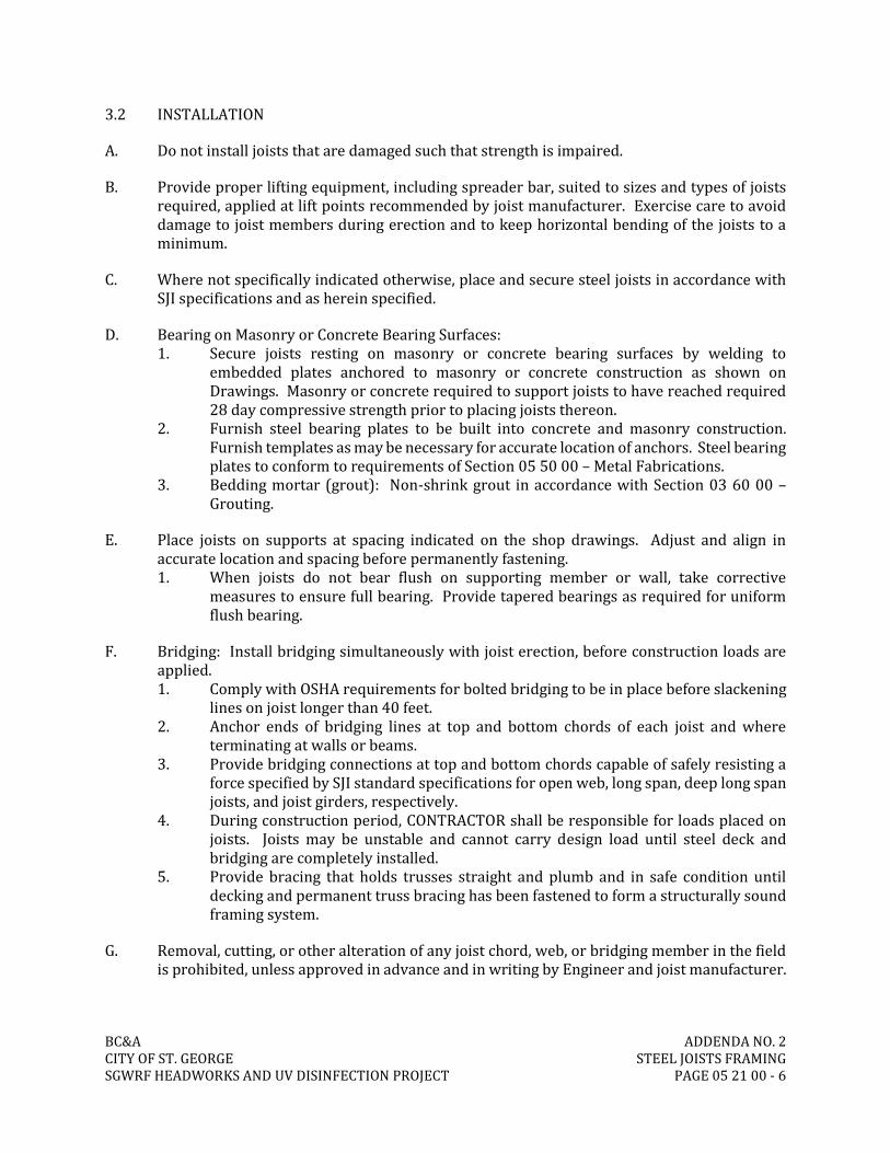
3.2 INSTALLATION
A. Do not install joists that are damaged such that strength is impaired.
B. Provide proper lifting equipment, including spreader bar, suited to sizes and types of joists required, applied at lift points recommended by joist manufacturer. Exercise care to avoid damage to joist members during erection and to keep horizontal bending of the joists to a minimum.
C. Where not specifically indicated otherwise, place and secure steel joists in accordance with SJI specifications and as herein specified.
D. Bearing on Masonry or Concrete Bearing Surfaces: 1. Secure joists resting on masonry or concrete bearing surfaces by welding to
embedded plates anchored to masonry or concrete construction as shown on Drawings. Masonry or concrete required to support joists to have reached required 28 day compressive strength prior to placing joists thereon.
2. Furnish steel bearing plates to be built into concrete and masonry construction. Furnish templates as may be necessary for accurate location of anchors. Steel bearing plates to conform to requirements of Section 05 50 00 – Metal Fabrications.
3. Bedding mortar (grout): Non-shrink grout in accordance with Section 03 60 00 – Grouting.
E. Place joists on supports at spacing indicated on the shop drawings. Adjust and align in accurate location and spacing before permanently fastening. 1. When joists do not bear flush on supporting member or wall, take corrective
measures to ensure full bearing. Provide tapered bearings as required for uniform flush bearing.
F. Bridging: Install bridging simultaneously with joist erection, before construction loads are applied. 1. Comply with OSHA requirements for bolted bridging to be in place before slackening
lines on joist longer than 40 feet. 2. Anchor ends of bridging lines at top and bottom chords of each joist and where
terminating at walls or beams. 3. Provide bridging connections at top and bottom chords capable of safely resisting a
force specified by SJI standard specifications for open web, long span, deep long span joists, and joist girders, respectively.
4. During construction period, CONTRACTOR shall be responsible for loads placed on joists. Joists may be unstable and cannot carry design load until steel deck and bridging are completely installed.
5. Provide bracing that holds trusses straight and plumb and in safe condition until decking and permanent truss bracing has been fastened to form a structurally sound framing system.
G. Removal, cutting, or other alteration of any joist chord, web, or bridging member in the field is prohibited, unless approved in advance and in writing by Engineer and joist manufacturer.

BC&A ADDENDA NO. 2 CITY OF ST. GEORGE STEEL JOISTS FRAMING SGWRF HEADWORKS AND UV DISINFECTION PROJECT PAGE 05 21 00 - 7
H. Remove and replace or repair damaged joists or other Work as directed by Engineer and/or joist manufacturer at no additional expense to Owner.
3.3 TOUCH-UP PAINTING: 1. Clean abraded, corroded, and field-welded areas and touch up with same type of paint
used for shop coating. 2. Field paint as specified in Section 09 90 00 – Painting and Coating.
END OF SECTION

BC&A ADDENDA NO. 2 CITY OF ST. GEORGE STEEL JOISTS FRAMING SGWRF HEADWORKS AND UV DISINFECTION PROJECT PAGE 05 21 00 - 8
THIS PAGE INTENTIONALLY BLANK

BC&A ADDENDA NO. 2 CITY OF ST. GEORGE OPEN SCREW PUMPS SGWRF HEADWORKS AND UV DISINFECTION PROJECT PAGE 43 27 10 - 1
SECTION 43 27 10 OPEN SCREW PUMPS
PART 1 – GENERAL 1.01 SUMMARY
A. This section includes four open flight screw pumps, complete with fully self-aligning upper
and lower bearing assemblies, monolithically cast ductile iron upper and lower shafts, stainless steel side rails, premium efficiency drive motors, high and low speed couplings and covers, concrete base-mounted parallel shaft gear reducers, full factory shot blasting and painting, spiral screed rods, plus all necessary hardware, fittings and anchors.
B. Related Sections: The following sections are related to this work. However, the list is not
exhaustive and other elements of the specifications also apply. Coordinate with these and others to furnish and install the specified equipment.
1. Section 11 00 00 – Equipment General Provisions 2. Section 26 20 00 – Low-Voltage AC Induction Motors 3. Section 43 20 10 – Pumps, General 4. Section 43 27 11 – FRP Screw Pump Covers
C. The environment for the screw pump motors and drives is unclassified. 1.02 REFERENCES
A. Antifriction Bearing Manufacturers Association (AFBMA)
B. American Gear Manufacturer’s Association (AGMA) C. American Society of Testing and Materials (ASTM)
1. A 36 / DIN S-235-JR - Specification for Structural Steel. 2. A 325 - Specification for High-Strength Bolts for Structural Steel Joints
D. American Welding Society (AWS)
1. Dl .1 - Structural Welding Code – Steel
E. National Electrical Manufacturers Association (NEMA)
1.03 DEFINITIONS A. Lift: The vertical distance measured from the filling point to the liquid delivery point. B. Touch Point: The lowest point in the screw pump trough where the first flights make contact
with the liquid being pumped.

BC&A ADDENDA NO. 2 CITY OF ST. GEORGE OPEN SCREW PUMPS SGWRF HEADWORKS AND UV DISINFECTION PROJECT PAGE 43 27 10 - 2
C. Chute Point: The upper level of the bottom of the screw pump trough. This chute prevents the water from flowing backwards into the trough if the screw pump is off.
1.04 SYSTEM DESCRIPTION
A. Open Screw Pump and Components: Each Screw Pump shall be furnished complete with spiral
steel fights, upper and lower cast stub shafts, upper and oil-lubricated lower bearing assemblies, stainless-steel side rails, concrete base-mounted, parallel shaft gear reducer, high & low speed grid-type couplings, coupling safety covers, premium efficiency drive motor, shot blasting and full factory painting and all necessary anchorage parts for operation in a concrete trough as indicated on the Drawings.
B. Performance Requirements: See Drawings to verify elevations and other design and installation requirements.
1. Number of pumps Four (4) 2. Minimum rated capacity per pump, US GPM 11,574 3. Minimum, Screw Pump Efficiency 73% 4. Angle of Inclination 38 5. Screw pump diameter 88″ 6. Torque tube diameter 60″ 7. Number of flights 3 8. Flight Pitch 75″ 9. Minimum torque tube wall thickness 14.2 mm / 0.559˝ 10. Minimum flight thickness 6 mm / 0.25˝ 11. Maximum Deflection 8.52 mm / 0.355˝ 12. Maximum Tensile Stress 19.49 N/mm2 / 2,826 psi 13. Touch point elevation 2,469.14ft. 14. Fill Point elevation 2,474.00 ft. 15. Chute point elevation 2,516.83 ft. 16. Maximum pumping point elevation 2,518.13 ft. 17. Drive unit floor elevation 2,520.67 ft. 18. Screw speed, RPM 26 19. Motor nameplate horsepower 200 20. Calculated Screw Pump Shaft HP 177 21. Recommended gear reducer HP rating* ~265* 22. Minimum Upper Bearing Diameter 200 mm 23. Minimum Lower Bearing Diameter 280 mm
*The Recommended Reducer Rating is the greater of either motor nameplate HP x 1.25 or Screw Shaft HP x 1.5.
1.05 SUBMITTALS
A. Shop Drawings and Product Data: A complete set of drawings, specifications, catalog cut-
sheets, and detailed descriptive material. This information shall identify all technical and performance requirements stipulated on the drawings and in the specification.
1. General arrangement drawings of the pumping equipment.

BC&A ADDENDA NO. 2 CITY OF ST. GEORGE OPEN SCREW PUMPS SGWRF HEADWORKS AND UV DISINFECTION PROJECT PAGE 43 27 10 - 3
2. Drawings of the upper and lower bearing assemblies. 3. Gear reducer dimensional drawings and rating data. 4. Motor drawings and performance characteristics. 5. Low speed coupling drawings and rating data, if applicable. 6. Lubrication system drawings, component descriptions, and operating data. 7. Screw pump painting schedule. 8. Bearing life calculations. 9. Screw pump deflection calculations shall be at maximum capacity and lift. 10. Screw Pump performance curves showing: capacity, efficiency, and screw shaft HP.
B. Screw Pump Calculations: Screw Pump design calculations shall be certified by the
manufacturer and signed by the manufacturer’s Professional Engineer.
1.06 QUALITY ASSURANCE A. Provide pumps and all equipment called for in this section from same screw pump supplier.
B. Require pump supplier to furnish and coordinate pump, motor, and pump components as
specified and scheduled below and to provide written installation and check out requirements.
C. Manufacturer Qualifications: Demonstrate minimum 20 years of experience in manufacture of open screw pumps which have been successfully utilized in domestic wastewater. Provide a reference list of at least 5 different installations in wastewater treatment plants of not less than 3 million gallons per day, where the manufacturer has supplied equipment substantially similar in design and characteristics to that proposed. The installations listed must have been in operation for at least 5 years. Include in the list the name, address, and telephone number of the person responsible for the equipment.
D. The equipment manufacturer’s shop welds and welding procedures shall be in accordance with the requirements of AWS Dl .1 Structural Welding Code – Steel or equal.
E. Screw pumps shall be manufactured according to ISO-9001 standards.
1.07 DELIVERY, STORAGE, AND HANDLING
A. General: As specified in Section 01 25 10 – Products, Materials, Equipment and Substitutions B. Packing and Shipping:
1. All materials shall be suitably packaged and braced to protect against damage during transit, handling, and unloading.
2. Manufacturer shall package equipment, be responsible for, and make good, any and all damage until the equipment is delivered to the job site.
3. Accessories shall be packaged separately in containers clearly marked “ACCESSORIES ONLY”.
4. A packing list, listing the contents of each container, shall be placed in a moisture proof envelope and securely fastened to the outside of the container.
5. Provide written storage procedures for all equipment.

BC&A ADDENDA NO. 2 CITY OF ST. GEORGE OPEN SCREW PUMPS SGWRF HEADWORKS AND UV DISINFECTION PROJECT PAGE 43 27 10 - 4
C. Storage and Protection: Protect the system components at the site and during installation
prior to project completion. As a minimum, provide cover, ventilation, and proper stacking to prevent warping of any equipment stored on-site.
1.08 WARRANTY
A. The screw pump is warranted to be free of mechanical defects for twelve (12) months after
installation or eighteen (18) months after shipping date, whichever date occurs first. 1.09 SPARE PARTS
A. For size of pump specified, provide the following spare parts packed and labeled for
warehouse storage:
1. One set of 200 mm Upper Bearing Assembly radial and axial thrust bearings and seals
2. One set of 280 mm Lower Bearing Assembly bearings and seals.
PART 2 – PRODUCTS
2.01 MANUFACTURER
A. The Screw Pumps and Screw Pump covers shall be a manufactured by one of the following
manufacturers.
1. Lakeside Equipment Corporation
2. Landustrie/Epic International Incorporated 2.02 MATERIALS
2.03 SPIRAL SCREWS
A. Material: Spiral Screws and end flanges of the torque tubes shall be fabricated of # S-235-JR
steel. ASTM # 36 steel is also acceptable. B. Outside Diameter: Each spiral screw shall have an outside diameter and number of flights as
indicated. Flights: C. Flights shall be die formed and shall have a minimum thickness as indicated.
1. Flights shall be helical shaped and continuously welded to the torque tube on both sides of the flight.
The leading edge of each flight shall be provided with steel reinforcement from the torque tube to
the outside diameter of the screw and shall be attached with continuous welds.
2. All welds between torque tube segments and between flight segments shall be in
accordance with AWS, DIN, ASTM, or API.
3. All welds shall be ground smooth on both sides.

BC&A ADDENDA NO. 2 CITY OF ST. GEORGE OPEN SCREW PUMPS SGWRF HEADWORKS AND UV DISINFECTION PROJECT PAGE 43 27 10 - 5
4. The flight to torque tube welds shall be shot blasted prior to factory applied painting. 5. The screw shall be statically balanced in the factory. 6. The screw shall be placed in a lathe and the flights shall be machined to a true radius.
D. Torque Tube:
1. Each torque tube shall have a minimum diameter with a minimum wall thickness as
indicated. 2. The upper and lower ends of the torque tube shall be equipped with internal
watertight bulkheads, inboard of the flanges. 3. All welds between torque tube segments and at torque tube end flanges shall be full
penetration welds as per AWS, DIN, ASTM, or API. 4. The end plates shall be provided with tapped bolt holes and indexes to fit the flange
of the shaft extensions. The shaft extensions shall consist of a flange with index to fit
the tube end plate and matching bolt holes. 5. A solid nodular cast iron upper drive shaft and lower stub shaft shall be fastened to
the upper and lower ends of the fabricated spiral screw with Grade 8.8 high-strength bolts.
6. The spiral screw shall be designed for a minimum deflection and stress and shall not exceed values given above. Calculate as a simple uniformly loaded horizontal beam between torque tube flanges including weight of flights, but not moment of inertia of flights.
7. Torque tubes shall be air pressure tested at the factory prior to shipment
E. Cast Shaft/Cast Flanges: Each upper and lower shaft-flange shall be constructed from a one-piece forging or casting of nodular cast iron. Provide indexes and matching bolt holes. A weldment consisting of a flange plate and shaft is not acceptable.
2.04 280 mm LOWER SELF-ALIGNING BEARING ASSEMBLIES
A. Oil-lubricated lower bearings.
B. Fully self-aligning in all three (3) axes.
C. No grease pump or grease lines are required.
D. Lower bearing housing shall be suitable for continuous or intermittent operation when
submerged in water or running in air.
E. The lower bearing housing shall be specifically designed to exclude water and shall contain
not less than two lip seals.
F. The lower bearing housing shall be suitably designed and anchored to the concrete
foundation to resist all loads including buoyant forces as would occur under maximum wet
well conditions. 1.05 200 mm UPPER SELF-ALIGNING BEARING ASSEMBLIES A. Wall Mounted and Base Mounted Bearings are acceptable bearing systems for this Project.
Manufacturer shall identify all changes to structural design necessary to accommodate prosed bearing system. Structural changes shall be clearly identified and submitted to the

BC&A ADDENDA NO. 2 CITY OF ST. GEORGE OPEN SCREW PUMPS SGWRF HEADWORKS AND UV DISINFECTION PROJECT PAGE 43 27 10 - 6
Engineer for review in the proposal phase. If changes are necessary, Contractor shall include costs to construct bearing supports as necessary.
B. Wall Mounted Bearing Option 1. The upper bearing assembly shall consist of spherical roller bearings which shall be
fully self-aligning in all three (3) axes.
2. The bearings shall be mounted in a wall-mounted cast iron housing designed such
that all the reaction loads are exerted on and into the pump station wall.
3. The thrust from the pump shall be carried by a spherical roller thrust-type bearing
assembly and the radial load shall be carried by a spherical roller bearings. A single
dual purpose bearing will not be allowed.
4. Bearings shall have a minimum life of 25,000 hours B-10 as defined by DIN-ISO under
maximum pumping loads.
5. Bearing housings shall have lip seals to exclude contamination and shall be provided
with grease fittings for manual greasing.
6. Bearing housings shall create a gas-tight seal between the equipment room and screw
pump trough without the use any additional shield or seal other than the bearing as
supplied.
7. The upper bearing shall be removable without removing the screw pump.
C. Base Mounted Bearing Option 1. The upper stub shaft shall extend through a grease lubricated upper bearing assembly
which shall consist of a split housing fitted with dual bearings, lower spring loaded lip seal, bearing spacer and upper spring loaded lip seal.
2. All of the thrust load from the pump shall be carried by a spherical thrust-type bearing assembly and the upper screw pump radial load shall be carried by a spherical roller bearing.
3. The two bearings (radial and thrust) shall be positioned in the bearing housing so that the pressure center of the thrust bearing and radial bearing intersects the axis of the screw at the same point to provide true self-alignment in all planes.
4. Both radial and thrust bearings shall be rated at a minimum of 100,000 hours AFBMA L10 theoretical design life, based on the dead weight of the screw plus the full weight of the liquid being pumped.
5. Upper stub shaft shall be grooved and positively locked into the upper bearing assembly by a split collar and locking halter ring.
6. A split bearing housing shall be provided to allow removal of the cover for inspection of the bearings without removal of the stub shaft or the entire bearing assembly.
2.06 DRIVE ASSEMBLY
A. The drive assembly shall be designed in accordance with the latest AGMA standards and
constructed for a maximum screw rotational speed as scheduled.
B. The reducer shall be designed for 24 hour continuous operation in the angular mounting
position corresponding to the inclination angle of the screw pump without leaking oil. The
output shaft shall be furnished with a double seal.

BC&A ADDENDA NO. 2 CITY OF ST. GEORGE OPEN SCREW PUMPS SGWRF HEADWORKS AND UV DISINFECTION PROJECT PAGE 43 27 10 - 7
C. The reducer shall have a mechanical rating of not less than 1.25 times the nameplate
horsepower of the motor or 1.50 times the brake horsepower of the screw shaft, whichever
is greater.
D. The thermal capacity shall be sufficient for a continuous maximum oil sump temperature rise
of 80 F above 110 F ambient when operating at maximum pumping load. The use of heat
exchangers or motor driven fans will not be permitted.
E. The housing of the gear reducer shall be close-grained cast iron of a minimum Class 30, with
removable top inspection covers, oil breathers and oil level indicators. Removal of the
gasketed inspection covers shall not necessitate draining of the lubrication oil or re-aligning
of the bearings. Oil breathers and level indicators shall be readily accessible and designed to
prevent oil leakage and entry of dirt, water and foreign matter into the reducer.
F. The helical gears shall be high quality alloy steel with an AGMA quality grade 11 minimum.
Precise alignment of gear, bearings and seals shall be maintained under all loading conditions.
G. The gears shall have a minimum L-10 life rating of not less than 25,000 hours.
H. The bearings shall have a minimum B-10 life rating of not less than 25,000 hours.
I. Gears and bearings shall be splash lubricated or pressure lubricated by an internal shaft
driven pump to effectively carry oil to all gears and bearings. A sight gauge or dipstick shall
be provided to verify the oil level.
J. The reducer shall have a nominal efficiency rating of 96%.
K. The reducer shall be furnished with an anti-reverse rotation backstop to prevent reverse
rotation of the screw during shutdown or inadvertent power failure.
L. Concrete Base-Mounted Parallel Shaft Mounted Gear Reducers: The gear reducers shall be
concrete base-mounted, parallel-shaft double or triple reduction units, complete with
anchors, back-stops and breathers.
2.07 HIGH AND LOW SPEED COUPLINGS
A. The drive motors shall be connected to the gear reducers with grid type high speed couplings
which have a service factor equivalent to that of the gear reducers. B. The gear reducers shall be connected to the screw pumps with grid-type low speed couplings
which have a service factor equivalent to that of the gear reducers. C. The high and low speed couplings shall be covered with stainless steel covers.
2.08 DRIVE MOTORS
A. The screw pumps shall be driven by 200 hp premium efficiency, 1,800 rpm, 3 phase, 60 hertz,
480 volt, horizontal, ball bearing, continuous duty, constant speed, Design B, TEFC, normal
starting torque, cast iron, unclassified location, foot-mounted motor with leads to gasketed
conduit box. Motors shall have class “F” non-hygroscopic insulation and a 1.15 S.F. at 40° C
ambient.
B. Motors shall be suitable for temporary use on an inverter at up to a 10:1 turn-down to
facilitate screeding of the screw pump troughs. C. Motor Mounting: Motors shall be connected to concrete base-mounted gear reducers with
grid type flexible couplings.

BC&A ADDENDA NO. 2 CITY OF ST. GEORGE OPEN SCREW PUMPS SGWRF HEADWORKS AND UV DISINFECTION PROJECT PAGE 43 27 10 - 8
2.09 DEFLECTION PLATES
A. Flow deflection plates shall be provided to curve around the uptake side of the screw to
deflect the liquid back into the screw as the screw rotate.
B. The flow deflection plate shall be fabricated of not less than 4 mm # T-304 St-Steel plate,
complete with stiffeners, and stainless steel anchors set on a maximum of 2 meters on center.
C. The deflection plates shall extend to an elevation equal to an angle of at least 40°.
2.10 GROUTING TOOLS AND SUPPLIES
A. Equipment manufacturer shall furnish a special spiral type screed and rod spot welded to the
outer perimeter of a flight for the CONTRACTOR to place the finishing grout in the trough
with the screw pump.
2.11 ANCHOR BOLTS
A. Equipment manufacturer shall furnish all anchor bolts of ample size and strength required to
securely anchor each item of equipment. Anchor bolts, hex nuts, and washers shall be # T-
316 stainless steel unless noted otherwise. Anchor bolts shall be threaded rods with washers
and nuts embedded. Expansion-type anchors will not be acceptable.
B. Anchor bolts shall be set by the CONTRACTOR. Equipment shall be placed on the foundations,
leveled, shimmed, bolted down, and grouted with a non-shrinking grout. 2.12 PAINTING
A. Full factory painting shall be accomplished in environmentally controlled conditions.
B. The screw pump, and bearing assemblies shall be SHOT blasted to SP-10 near white metal
finish before factory application of coating system per coating manufacturer
recommendations.
C. Minimum final coating DFT shall be 300 microns / 12 mils PPG-Sigmacover # 880 GF glass-
flake epoxy or approved equal.
D. Electric motors, speed reducers, and other self-contained or enclosed components and shall
be supplied with the manufacturers’ standard finish coating.
E. An appropriate quantity of Screw Pump touch-up paint shall be provided and used and
applied per manufacturer recommendations to repair any and all scuffs, dings, scratches,
chips and other deformities or deficiencies to the manufacturer coatings in order to meet the
original specified requirements.

BC&A ADDENDA NO. 2 CITY OF ST. GEORGE OPEN SCREW PUMPS SGWRF HEADWORKS AND UV DISINFECTION PROJECT PAGE 43 27 10 - 9
2.13 SCREW PUMP COVERS
A. The screw pump supplier shall provide covers as specified in Section 43 27 11 – FRP Screw
Pump Covers and shown on the Drawings. Cover color shall be selected by Owner.
PART 3 – EXECUTION
3.01 EXAMINATION A. Verification of Conditions: Inspect all components for shipping damage and conformance to
specifications. 3.02 INSTALLATION A. Install products in accordance with manufacturer’s instructions and as specified in this
Section. 3.03 TESTING A. After complete installation of the pump(s), the unit(s) shall be field tested to confirm the
following:
1. Equipment has not been damaged in transport and installation.
2. Equipment is properly installed.
3. All components are properly connected and established tolerances are observed.
4. Equipment is free of objectionable vibrations and overheating parts.
5. The screw pump is operating freely.
6. Equipment is not overloading any part.
7. Equipment has no electrical or mechanical defects.
3.04 MANUFACTURER FIELD SERVICES A. The manufacturer shall schedule three (3) trips to the project site of a factory-trained,
qualified representative to provide technical assistance to the contractor during erection of
the equipment, placement of the grout and including start-up and operator training. Each
trip shall consist of a minimum of 8 hours on-site and available for the above equipment
commissioning services. 3.05 OPERATOR TRAINING A. Training: As specified with start-up.
B. Provide operator training for OWNER’S personnel after the system is operational.

BC&A ADDENDA NO. 2 CITY OF ST. GEORGE OPEN SCREW PUMPS SGWRF HEADWORKS AND UV DISINFECTION PROJECT PAGE 43 27 10 - 10
END OF SECTION

BC&A – 3/19/18 ADDENDUM NO. 2 SGWRF HEADWORKS AND UV DISINFECTION PROJECT PAGE 5
ATTACHMENT 2 REVISED DRAWINGS