Embed Size (px)
Citation preview

Missouri University of Science and Technology Missouri University of Science and Technology
Scholars' Mine Scholars' Mine
International Specialty Conference on Cold-Formed Steel Structures
(1971) - 1st International Specialty Conference on Cold-Formed Steel Structures
Aug 20th, 12:00 AM
Design and Testing Composite Open Web Steel Joists Design and Testing Composite Open Web Steel Joists
J. A. Cran
Follow this and additional works at: https://scholarsmine.mst.edu/isccss
Part of the Structural Engineering Commons
Recommended Citation Recommended Citation Cran, J. A., "Design and Testing Composite Open Web Steel Joists" (1971). International Specialty Conference on Cold-Formed Steel Structures. 3. https://scholarsmine.mst.edu/isccss/1iccfss/1iccfss-session6/3
This Article - Conference proceedings is brought to you for free and open access by Scholars' Mine. It has been accepted for inclusion in International Specialty Conference on Cold-Formed Steel Structures by an authorized administrator of Scholars' Mine. This work is protected by U. S. Copyright Law. Unauthorized use including reproduction for redistribution requires the permission of the copyright holder. For more information, please contact [email protected].
DESIGN AND TESTING
COMPOSITE OPEN WEB STEEL JOISTS
BY
J. A. CRANl, P. ENG.
Introduction
Traditionally, most buildings ·have been constructed in a
utilitarian manner. The consideration of low first cost far out
weighed the considerations of maintenance and future renovation
costs. In the past decade, rapid technological change has spurred
a dramatic shift in design emphasis. In order to avoid early
obsolescence, designers are now concentrating on building flexi
b1li ty.
For example, owners of schools and modern office buildings now
demand the utmost in flexibility of interior design. Large open
areas; long, column-free spans; moveable partitions; the ability to
move heating, ventilating and air conditioning ducts; and ease in
accomodating new electrical and communication requirements are man
datory. A most economical method of providing long clear spans, a
high degree of services, and built-in flexibility of space utiliza
tion is the composite open web steel joist.
Advantages
The main advantages offered by composite open web steel joists
(OWSJ) are as follows:
1. Economical long spans. Fig. 1 compares the cost per square
foot of installed floor for various spans of composite and non
composite OWSJ. Fig. 1 is based on the following parameters:
a) Joist depth - 32. II
b) Joist spacing - 5'0"
c) Steel floor - lis" deep, ZZ ga., 6"c-c ribs
d) Welded wire fabric - 6 X 6 10/10
e) Concrete slab - 4" total thickness
f) Stud shear connectors (composite joists only)
g) Column and girder costs are not included.
It can be seen that for spans of 37' and greater, composite open
web steel joists offer cost savings. Below 40', the savings in OWSJ
steel weight do not fully compensate for the added expense of shear
connectors. Clear spans of 40' are commonplace in modern office
towers while schools designed to an open plan require spans of
50-65'. Therefore, composite joists offer significant savings when
used in schools and office towers.
Z. Increased Natural Freguency. The natural frequency and amplitude
of long span floor systems sometimes subject a building's occupants
to objectionable vibrations. Composite joists have vibration charac
teristics superior to those on non-composite joists.
3. Increased Stiffness. The concrete-steel interaction results in
composite joists having greater stiffness than non-composite joists.
In practical terms, composite joists can be shallower than non-composite
joists, or, for a given joist depth, live load deflections are sig
nificantly less when composite joists are used.
Shear Connection
As indicated when economy was discussed, the prime difference
between a composite and nan-composite joist is the presence of a
*The Steel Company of Canada, Limited
Sales Engineering Manager, The Steel Company of Canada, Limited, Hamilton, Ontario, Canada
shear connection. For both types of joists, the bottom chord and
web systems are identical. However, because the presence of a shear
connection in a composite joist allows the concrete floor slab to
act with the steel joist, the top chord of a composite joist oan be
considerably 1 ighter than that of a non-composite joist.
Because the material cost savings in the top chord must be
sufficient to offset the added cost of a shear connection, it is
desirable to have an economical connection. To this end, Stelco*
conducted a series of push-out tests to evaluate various types of
shear connectors .1
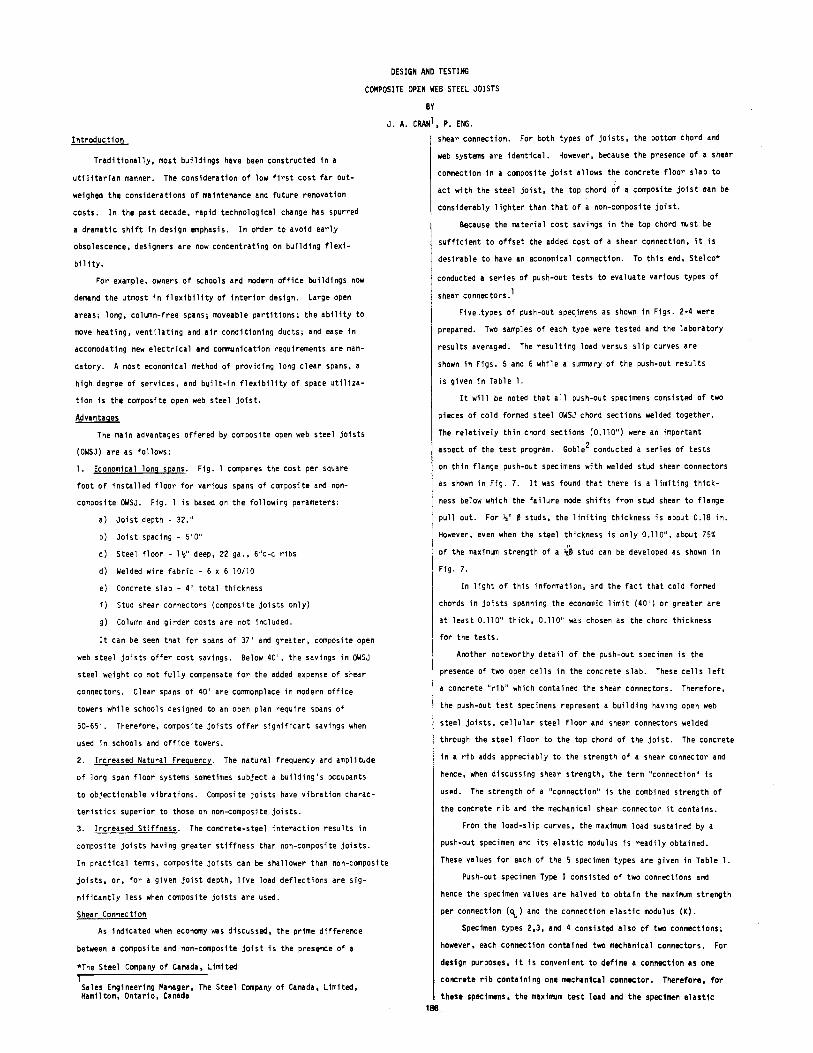
Five .types of push-out spec.imens as shown in Figs. 2-4 were
prepared. Two samples of each type were tested and the laboratory
results averaged. The resulting load versus slip curves are
shown in Figs. 5 and 6 while a summary of the push-out results
is given in Table I.
It will be noted that all push-out specimens consisted of two
pieces of cold formed steel OWSJ chord sections welded together.
The relatively thin chord sections (0.110") were an important
aspect of the test program. Goble2 conducted a series of tests
on thin flange push-out specimens with welded stud shear connectors
as shown in Fig. 7. It was found that there is a limiting thick
ness below which the failure mode shifts from stud shear to flange
pull out. For Is" ~ studs, the limiting thickness is about 0.18 in.
However, even when the steel thickness is only 0.110", about 75%
of the maximum strength of a a;j, stud can be developed as shown in
Fig. 7.
In light of this information, and the fact that cold formed
chords in joists spanning the economic limit (40') or greater are
at least O.liO" thick, O.liO" was chosen as the chord thickness
for the tests •
Another noteworthy detail of the push-out specimen is the
presence of two open cells in the concrete slab. These cells left
a concrete "rib" which contained the shear connectors. Therefore,
the push-out test specimens represent a building having open web
steel joists, cellular steel floor and shear connectors welded
through the steel floor to the top chord of the joist. The concrete
in a rib adds appreciably to the strength of a shear connector and
hence, when discussing shear strength, the term "connection" is
usod. The strength of a "connection" is the combined strength of
the concrete rib and the mechanical shear connector it contains.
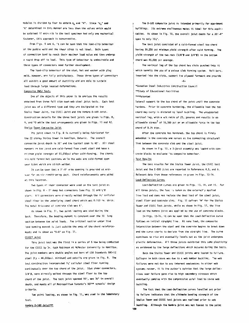
From the load-slip curves, the maximum load sustained by a
push-out specimen and its elastic modulus is readily obtained.
These values for each of the 5 specimen types are given in Table 1.
Push-out specimen Type I consisted of two connections and
hence the specimen values are halved to obtain the maximum strength
per connection (qu) and the connection elastic modulus (K).
Specimen types 2,3, and 4 consisted also of two connections;
however, each connection contained two mechanical connectors. For
design purposes, it 1s convenient to define a connection as one
concrete rfb containing one mechanical connector. Therefore, for
these speci~~~ens, the maximum test load and the specimen elastic 188 0

1----------------------- . ----·----- I T'I_!'EE
I , ~ 1
'
__ jiJ. -- ------------, I
~ ' 1
- 2- 3,4 ¢ Pur!JI~ hdl . (E•ch 5:d~J
l I I -·
[~~-?-~;~~~~~-~-~~·~ -=---=---= ---lil - L..J
PUNCH ~'9' •oL<
IJ I _l_u ______ -
------- .l.r+----- --
=~ _:-__:-_--:---=--f.;.-_---_-~--:::_ -=-_=1 IJ' "!--__2- H~f w.th Plv1 Weld -------_DI------- .. •! t£tJchs,JE:)
·----- -- :_~------- _; ·: --------- ~ c-.·
J, ~ • ..£.! • a. 104~ • ~ ·~l.JI''---1--+ • { i;---4
1ft. st 01
<-,
~ ~
~
""' ~ ' <..-. 'I
~ .....
,, (,l <::. Q
(.,
"'
~
<>..
"'
~
(/)
"'
I I
.... <::.
COST PER FIIVISI/EO ..JOt/ARE FOOT, doi!Cl".r , I ..
:--
"' <>
'' i
0
' ':
<::. <::.
~ ~ "' ~ "' "' <)
..0
~
----- . T'IP~3
Non:: All oth•• d•i>o;ls s;,.;w Fl~'. 3 ousll-OOT ~P~ctMEN_(U~~-~?-.Ii~3_L "to TVff 1 "' -·- .u ·. ----- .
Lll' . i.!' , ; ; _i .. ' I ..... ~~-~--LJ .. ~
! I ·----------1
,
m 11 I II I
I----------n;--- ----- -
:;;=~--~~~~=-~~~~= =-= =--=- -= =-=-t!.-:..:-~ ~ ___:-_- -= = ~
lo I LLJ
.9_RWlAR PLAI>J WACf\H,:
t'%z 'o D ''-1<: 1. D. 101• .
2 -Ilia<. he~ W;H _fl•j" ;.;_,_iii (E'ncf!- sile)
HPE 4-
~ }Y!lliJ__>j+·;s t'·~-1 I I :) : , tl 0 •
--------t~+---:..-_-_---=- ~.-: L:\ '!! ·-t~ -- - Pl T- - -- ttJ 0 0 I I ... -=-==-=--- -~---_- -=---= . ."I +-r ~;;;>,. ------ -nr---
----hJ------- 1-Strtlpwofhf; = =--=- _ - - -fj'~ - - - - - - Pluj IV< Ids (Ert,h S·t~ I l' r------1 - - ------- [TYPE_~~
N<>T£' Allo+nor drio;ls S•noii<i"r-~,. 4 Pt>SH·cur·-;P~:~Mt:N__(T'IP£~:___4~_5_~~~ I ...L,____~~~~-J: _____ ·-- .. --~==-=-"~cc:·c:':.Cc.;_..,-_c·'-'--_ ... _ c.:__~_-c _____ .. ---------··--------'
+--
c-· L ~-
------ .,
s~+---t ~--· -_ ~-~3rT Yt~ • ---- - l_---_ ---.:-:..LN ... '. ' --~· -- ' -- -- --------~ ~ --:::.- - _.;_l ;;-:
----------- c:-~ s.t"\" I . ____ ____.1 __ -:....__r_
s!.o
PLAN
t m 1 I I I I I
·------1
-1-·
~-R_.ItL 1. Stu I chord: t" 0.110 :• 2
.4s. ~ J, 511 ·~· FJ = 55 1'-! •. 1.
2.. S·hJtl: fz•tiJ, 3" lcn3 3. CoNr,t.f~: f, 1 • 3000 p•i.
4-. DocK: 1'/z "drep) e29~-concrt~ r-;b: JVz ">t 2'/c~ ,·c.-c.
1J3.T LMD
-----~---~- t~-~-= rl·· - . ~ ! • (\; "1
--- ::: ~--:-_~ ~-!~ -~ ~ -=_ -== ~ ~~ "' ... -'
~i ~
,_L~ --
I I I LJ.J
£R D"'T_ J ~~V~l}Q~
. ~ ::L I
Fl&.t PU51-l·DuT SPWIIEN(T'if'F 1) ..:.=....~=--:.~~~-=---=---====~-:.=-~-=-=-- :.:._· . -

i
lf) a f. 40 n~ 35 y-o-___ Q__ 3;4'' s·ruD
~ 30 25 / 0 5. ' 0
~ e.o _, 15 w
10 a:: ::> ....J 5 ~
0
~--o-- (e 51UD
0 ~------o- Yz''sTuo
I ---~------L-
6:; FULL (J]
0 = STt'D ~T-iL·\;· ..
.1 . 2 ,3 .4 . 5 ,6 FLANGE THICKNfSS-IN.
FI6,_J __ -::-=c~-?_!UD_ Ct~.PNII',/ VS _ S}T_Eb-~}HICI\NC~~'
__ ( Fr~~~ REF. 2)
-~ -; r . . . "': .. N W ~
~ u; = • ";l if • C")
0 ... ... .. 9: ... " ~ ";l
f " I ~
~ .. !?
0
li ...
i!' it ~ , ~
... ID if !!
E ID
" 0 0
" " .. • s n
0
" " ~ " !I :: S" 0 ... " ;;:- ;;;-
0 0 i " ..
~ n 0
i! ::r .. ... " .. ;;-.. .. ~ ... ~- .... .,. ... ... !. :: ..
~ ::r 0
i
! 5 3. n
~~I I I II~ 2 , ... c: ,
"' ID "' ... ~ ~~ "' .. --o -< .. !I ;:;: ::
~ :on "' ~~
.. ~ c:
" .-.. -< ... "' ~c: .. o~
ID
~ < -~ C")
c:
~~I 0 :: " " .. "'"" .... ~ ... 0
"
!!: I~ 1~ 1== 1== 0 0. 0 0 0
~ 1° I~ 1° 1° ~ ~ ~ ~ ~
... I. IN J"' . •_· .. . ·- ............ U'l "' ... "'
~
;: .. .. • " • :' ~ l C")
0 ,.. " ··~I~I~IEI" ~~ U'l U'l w Ul - .... :00 ~
"' 0 "
i'tJ·-
15
"ff "-
"" ..___.. D 10 < 0 -'
5
L _____
I
~ 5 "' ~ _J
L-. ·-
r 401
30
---~- §::.2;·~:~£ T'lre+~w~:;~w~<-u
l'(VE1 - S Tc.>tl
PU'DDL'E w E '-0 I
0.1 o.a o.3 o+ o.s , SLIP {IN.) ,
~-£' fl;-: ~ '----,~~=~~!?~~ ,~.hJ~-~t1~~.!2J]}~~~-~~•~ ~-~iLc I
·- --- -------·---------- ____ _J
TYPE 5 - .STR"P
f ~ · D1JCJ . t T1PE .3- llA.T
--~-__J_______ -l
o. I l>. f l>. 3 O. 4- O. 5
SLIP (IN.J
Fl6 . __ 6_ ·--~1.9A!>.::.,? Ll£.f,~_R,y_~_S,_(!JPE~3l ~_5) -~-
modulus is divided by four to obtain qu and "K". Since "qu" and
"K" determined in this manner are less than the values which would
be obtained if each rib in the test specimen had only one mechanical
fastener, this approach is conservative.
From Figs. 5 and 6, it can be seen that the load-slip behaviour
of the puddle weld and the shear strap is not ideal. Both types
of connection tend to reach their max·;mum load value and then undergo
a rapid drop off in load. This type of behaviour is undesirable and
these types of connectors need further development.
The load-slip behaviour of the stud, hat and washer with plug
weld, however, are fully satisfactory. These three types of connectqrs
all exhibit a good amount of ductility and are able to sustain
load through large imposed deformations.
Composite OWSJ Tests
One of the objects of this paper is to analyze the results
obtained from three full size open web steel joist tests. Each test
joist was of a different type and they are designated as the
Stelco Tower Joist, the CSICC Joist and the Hambro D-500 Joist.
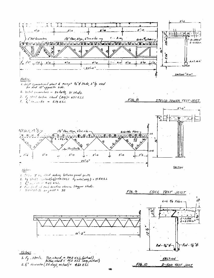
Construction details for the three test joists are given in Figs. 8,
9, and 10 while the test arrangements are given in Figs. ll and 12.
Stelco Tower Composite Joist
The joist shown in Fig. 8 is currently being fabricated for
the 22 storey Ste leo Tower in Hamilton, Ontario. The avera ll
composite joist depth is 30" and the typical span is 40'. All steel
members in the joist are cold-formed from sheet steel and have a
minimum yield strength of 55,000psi after cold-forming. The chords
are cold formed hat sections while the webs are cold-formed open
seam tubes which are stitch welded.
It can be seen that a 2'-0" wide opening is provided at mid
span for an air conditioning duct. Chord reinforcements were added
at this location.
Two types of shear connector were used on the test joist as
shown in Fig. 8 - 2" deep hat connectors (see Fig. 3) and \"0
studs. All connectors were directly welded through the l\" cellular
steel floor to the underlying steel chord which was 0.153 in. thick.
The total thickness of concrete slab was 4".
As shown in Fig. 11, two point loading was used during the
test. Therefore, the bending moment is constant over the lD' long
section between the point loads. The critical section under live
load bending moment is just outs ide the ends of the chord reinforce-
ments and is shown as 11A-A 11 on Fig. 11.
CSICC* Joist
This joist test was the first in a series of 5 now being conducted
for the CSICC by Dr. Hugh Robinson at McMaster University in Hamilton.
The joist members were double angles and bars of CSA Standards G40-12
steel (Fy- 44,000psi. minimum) and details are given in Fig. 9. The
test construction incorporated l\" cellular steel floor running
continuously over the top chord of the joist. Stud shear connectors,
3/4"0, were directly welded through the steel floor to the top
chord of the joist. The test joist spanned 50', was 36" in overall
depth, and meets all of Metropolitan Toronto's SEF** schools' design
criteria.
Two point loading, as shown in Fig. ll, was used in the laboratory
test.
Hambro D- 500 Joist***
The D-500 composite joist is int@nded primarily for apartment
buildings. Its extreme shallowness makes it ideal for this appli
cation. As shown in Fig. 10, the overall joist depth for a 20'-4"
span is only 12'>".
The test joist consisted of a cold-formed steel top chord
having 39,200 psi minimum yield strength after cold forming. The
yield strength of the two rods (5/8"~ and 3/4"~) in the bottom
chord was 45,000 psi average.
The vertical leg of the top chord has slots punched into it
which permits the use of a unique slab forming system. Roll bars,
inserted into the slots, support the plywood formwork and provide
-6-
*Canadian Steel Industries Construction Council
**Study of Educational Facilities
***Patented
lateral support to the top chord of the joist until the concrete
hardens. Prior to concrete hardening, the allowable load the top
chord may carry is dictated by local buckling. The unsupported
vertical leg, with a w/t ratio of 23, governs and results in an
allowable stress3 of 15,300 psi or an allowable force in the top
chord of 8.25 kips.
After the concrete has hardened, the top chord is firmly
embedded in the concrete and serves as the connecting structural
link between the concrete slab and the steel joist.
As shown in Fig. 12, a 3-joist assembly was loaded with con
crete blocks to evaluate its composite behaviour.
Test Results
The test results for the Stelco Tower Joist, the CSICC test
Joist and the D-500 Joist are reported in References 4,5, and 6.
Relevant data from these references in given in Figs. 13-19.
Load-Deflection Curves
Load-Deflection curves are given in Figs. 13, 14, and 15. For
all three joists, the load is taken as the externally applied
live load and does not include the dead load of the steel joist,
steel floor and concrete slab. Fig. 11 defines "W" for The Stelco
Tower and CSICC Test Joists, while as shown in Fig. 12, the live
load on the Hambro joist was applied by the use of concrete blocks.
In Figs. 13-15, it can be seen that the Load-Deflection curve
follows an initial stra~ght line. At some load, the composite
interaction between the steel and the concrete begins to break down
and the curve starts to deviate from the straight line. The curve
continues to rise and eventually levels out as the joist undergoes
plastic deformation. All three joists exhibited this same plasticity
as evidenced by the large deflections which occured during the tests.
Both the Stelco Tower and CSICC joists were loaded to failure.
Collapse in both cases was due to a web member buckling. The web
failures were not due to any inherent weaknesses in either web
system; rather, it is the author's opinion that the large deflec
tions near failure gave rise to high secondary stresses which
eventually combine with the compressive axial load to cause web
buckling.
189
The fact that the Load-Deflection curves levelled out prior
to failure indicates that the ultimate bending strength of the
Stelco Tower and CSICC test joists was realized prior to web
buckling. Although the Hambro joist was not loaded to the point
- s_':-p
I ! 1s' h·
+ ;- ~-*- ·--~-1---± + .s~o -·- --- ...
5'-o
L A. t.f!JZ i~.f i ~ 0./53 jr,,
L: I
------------ ----------~-----·_g,_t)!.o_•~------ ------,-----~
Nofrs
/. Jtiof-s;mmo/r;.-~/ t~6~vf' e~ct/f 1z"t/sf.,Js; 3"J· liSt:'/ (.,. f',.tr' 15 1 "/?~s:f~ .s;/~.
2. 'ir/-.1 (rnwdcr~ - 3o ~t?~~ 21 slv/s. • J :k~l {,,;;"" (hen/ (t1Vj,}=: 63./ k.S./.
1. (;'(r•·o.-fc = 5./~K.S.I.
0J~~
;. .~//·,. -,, -i·r d"rl 111 ,J,.·~y b~+wan f~"~t P"'·+s. Z. ~j :-f•d! · .. :rl,n4(~'j)•5~-2k.$./ f, '-'-"'b(.,.v~) • S/.5'/<.S./ .
•. (.' ,, • ,;. ,- 1-ic'S I(.S./,
4 {, .- :; .. •I _,/ o::,-, 0 1, /unl.-m tAt"'''• Sf"'JJ~"' s-lv/s. kl~!::;lr/s cnjcisf~ 32
F/6 8
F/6. ~
-- -- -------- __ .fl}~-:_g.~_' -·------~-~-_:--~ ·---------...! ..
Nc.&s: t. F..y __ st~cl:_ 7b?.-~ltu . .{_ =-..s'!?.e Ks~.__,Ue.ftM/) )
8•114111 c.h.,lf = 1-S.o K.S:/. (t.ltl!hlld~/ Z. (' etnrvcfe { :26 cl.1p, etC.t(ltl/}= -/:60 /(.S./. Flffi 10
UJO
cs;cc TEs.r Jets r
SFC.Tto/11
e-seo nsr Jo;_a_

(,-,·r_: i'lf/ ·
I •. : ! r, i· --
L - .. ' i i -1 ' -
" .._, I 1 ·cc=-"=--c---,-_.,-,,.,-, ·c ·cc. c . · -- · - ·--- 'l
E~./v\67-Y~;'~~~~~=~ Zo ~ 1-•
. . Et.EM Ti~tJ :--TT --
·r-r:: . ,._t -~-' -! : ! ' I I ! i i i · · ·' 8 ':..o ~- · . . · · ·
: i 1 ·r··-!·:··~ ~·~··~1· :·~·~·;-:f. . 1- ---c I • - ~- ; ' -·i ••
i : ' : I ' .. I I i i I ' i I ' ' I ~ " ' : I I I .
· j- . LJ SEC. A-A _ . : -· ·r .J_--[-1
I I I I I . ' ' I I ' I I ' - . I :-- - - I - - ! : i .
I i I I i ! ' i I I : ! ! i ' I
: I ! !'_ '_ I t l '._ i ; : : . :_ . I
-~ -" - , _I --r- ~- --++ I . t ·_- I , - -; ' ' I ! I i l : . ! I ' + ~.F(~./2. I --l !D-5oo: 1Jtl/5T r£51 Alfdt'ftt1f£1/EtUt
.---5o
4f
";;' p;
8.St> l I
o to §
10
J J ~ .. ~
.. f~
\ It
I _j __ _______l___ ____ l §H-~_----'
2. 3 ... 5 " 1 8
& - I11D- SPAN OE.FLEc.Tto/'1 (IN·)
....E~:J*=~2AR;:..,J?ffi.4~~;n2tt-<;:Yc!~~r:-~~"- c;_~JS(. ~-~81 ~I"--=~c--~-- --~~·-
'vi
r:: --- ,_!____ :J
t~:_=~'f;--,~_J_''~,:~,s~~:~-~~;-~_''_l~_,,~~t ~' ------ ---- - 50 -Q -- - -- ' - --- -~j
C51CC JOIST
' I '
-.----- ---.------ ; -I . r--1
I - , i i i I • • - ; . -~---Llli: -~!- i : ; ' : . -, ----- i- i -,-,-- I - -+---4--
~~l_~l~ _ I i ~J~L~o ToWCI( Jot.ST -=±l,J, 1 --' __ _
- 06.-i( cs~Z' -i s-ntr~ TOf,V'U Jo'tsr /EST ARI?AIV6Uf€NT
~-- _;_ -t---! -++-H +++++-t- -[ --- j- --+--: -;----;-·o - ;----r-r--,~-,---
LOAD - W __ l~f?) -~ 0 1\') ()I
0 0 ,-- ------.----~ - ---r
j-> ----- ---..~~. -~~t.
, <>--Ci' .,., ----
l/1 ~ 3 --4 9 m r r (/\·
(' () ., 0 )> ~(II
1::1, -\ I Cl 0 et .., _£ .., "' fTI 11 :;; }Ill' "~ I"' :j
·f' 0 (_ 1,-, z 0 0 fi. lz -::::--1 £-lrl
If'.
~~~ '! f'l
!I
~

of collapse, once again, the levelling out of the Load-Deflection
curve would indicate that the maxi rum 1 ive load applied during
the test is close to the ultimate live load the test assembly
could have supported.
A theoretical r.oad-Oeflection curve is also plotted on Figs.
13-15. In all cases, complete interaction between the concrete
and steel and elastic behaviour is assumed. For the Stelco Tower
and CSICC test joists, the theoretical deflections shown were
computed by the method of virtual work and considering the joists
as trusses. The concrete slab area was converted to an equivalent
steel area and this area was taken as that of the top chord. (The
area of the steel portion of the top chord was neglected for reasons
to be explained later.) The theoretical deflections shown for the 5Wl3
Hambro joist were calculated from bending theory ('3!!'4rl) with a
10% increase to account for shear deflection. Once again, the area
of the steel top chord was neglected.
In all deflection calculations, the full width of the concrete
slab was used.
A comparison of the theoretical and actual deflections are
given in Table II. No discernable pattern is evident which would
indicate that the theoretical methods applied (virtual work and
bending theory) are, strictly speaking, applicable to a composite
joist. It is felt that more accurate theoretical results can
be obtai ned if composite beam theory which accounts for s 1 i p
between the concrete and steel (partial interaction) were applied.
In any event, it appears that the normal method of calculating
joist deflections - bending theory with a 10% shear deflection
allowance- gives a reasonable estimation of deflection.
As exnlained in Reference 7, the presence of open cells causes
increased slip between the concrete and steel. Thus, when cellu-
lar steel floor is employed (as in the case of the Stelco Tower
and CSICC test joists), it is suggested that the deflections cal-
cu l a ted by bend i 09 theory with a shear a 11 owance, be further in-
creased 10-20. to account for slip.
Measured St.!'_~
l·leasures strains for the Stelco Tower and CSICC test joists
are shown in figs. 16-19. In Figs. 16 and 18, strain blocks are
shown for two conditions a) when the live load uwll on the
composite joist results in a bending moment aporoximately equal
to the working bending moment, and b) the last recorded strains
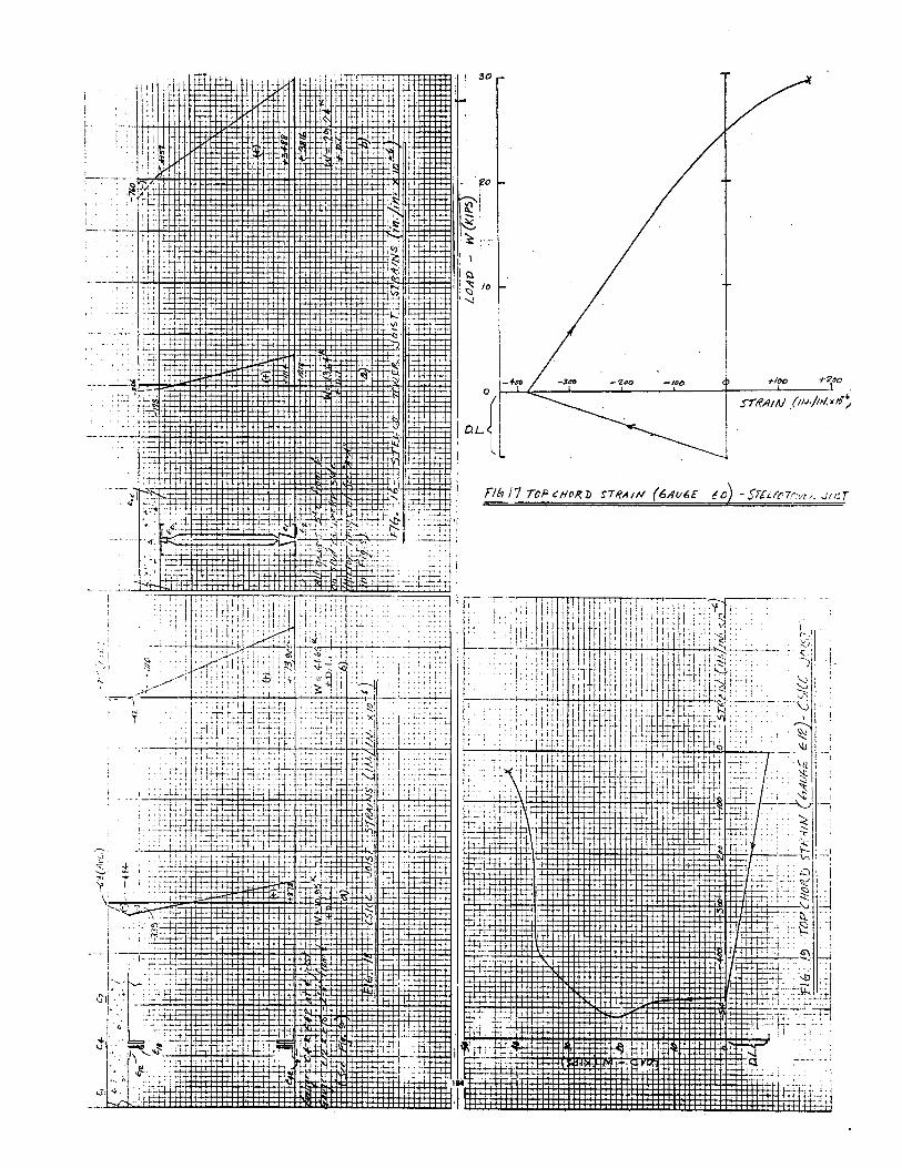
prior to joist failure. In Figs. 17 and 19, Load -Strain curves
are oresented for the top chord of each joist.
The yield strain for the bottom chords of the Stelco Tower
and CSJCC joists are 1893 and 1776 in./in. x 10-6 respectively.
From Fiqs. 16 a) and 18 a) it can be seen that the measured strains
when the joists were under working bending moment were well below
the yield strains of the bottom chords. The loads associated K
with working moment were about 13.64 for the Stelco Tower Joist
and l0.95K for the CSICC joist. From Figs. 13 and 14, it can be seen
that under working conditions, both joists are on the straight line
portion of the Load - Deflection curve and are behaving elastically.
From Figs. 16 b) and 18 b), it can be seen that prior to
joist collapse, the bottom chord strain of both the Stelco Tower
and CSICC test joists was well beyond the yield strain of the
steel. The presence of these yield strains is a further indication
that the ultimate bending strength of both joists was achieved
prior to joist collapse.
In Figs. 17 and 19, it can be seen that the dead load of the
steel floor and concrete slab, as well as shrinkage, places com
pressive strains of -394 and -484 in./in. x 10-6 in the top chords
of the Stelco Tower and CSICC test joists respectively. As the
live load "W" was applied to the test joists, contrary to what
might be expected, the top chord compressive strain diminished. I~
fact, the Stelco Tower top chord went into tension and the CSICC
top chord approached zero stress. This behaviour indicates that the
top chord is actually working in conjunction with the bottom
chord to resist the compressive force in the concrete slab of the
composite joist. In practice, the short lever a1"11! between the
top·chord and the concrete slab, as well as the relatively low
level of strain in the top chord, means that once the concrete
slab has hardened, the top steel chord of a composite joist can
be neglected.
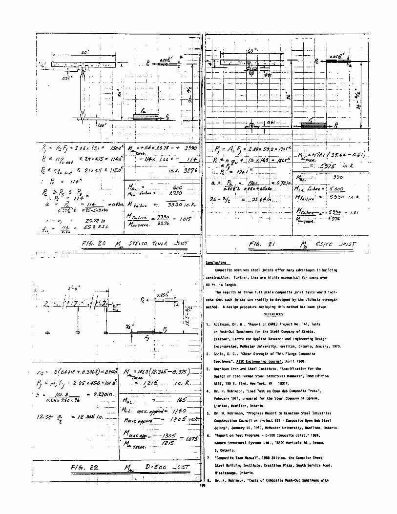
Ultimate Strength Calculation
The ultimate bending strength calculations for the Stelco Tower,
CSICC and Hambro composite joists are given in Figs. 20, 21, and 22.
Basically, the calculations hinge around the strength of the connec-
tion between the concrete and steel. The compressive force in the
concrete cannot exceed the crushing strength of the concrete, the
tensile force in the steel cannot exceed the yield strength of the
steel, and neither the compressive force nor the tensile force can
exceed the ultimate strength of the concrete-steel connection.
For example, let's consider the Stelco Tower joist. Referring to
Figs. 8 and 20, the maximum tensile force the bottom chord of the
joist can develop is 130K. From Table I, the ultimate strength
of a hat connection is 4.75K, and the ultimate strength of a 1/2"
diameter stud connection is 5.5K. On one side of the joist there
were 24 hats between the point of zero and maximum moment, and on
the other side there were 21 studs. Therefore, the ultimate strength
of the concrete-steel connection is ll4K on the side containing the
hats and ll5K on the side containing the studs. Consequently, the
force in the steel cannot reach its yield force but is 1 imited to
the strength of the steel-concrete connection- ll4K. The force in
the concrete is equal and opposite to that in the steel. The couple
created by the steel force and concrete force is, of course, the
theoretical ultimate strength of the joist, in this case, 3276 in. K.
A similar procedure was used for the CSICC and Hambro joists. In
the case of the CSICC joist, the ultimate strength of a 3/4" diameter
stud was taken as 14.3K from Reference 8. For the Hambro joist, the
steel-concrete connection was assumed fully effective because the
the top chord is securely embedded in the concrete slab and the
concrete slab does not contain open cells.
From Figs. 20, 21 and 22, it can be seen that the maximum error between the theoretical ultimate strength calculated in the above manner and the ultimate strength for the two joists, which were loaded to failure, was 1-l/2%, and for the Hambro joist, which was not loaded to failure, was 7-1/2%. It should be noted that the theoretical moment in all cases is less than the maximum applied moment.
Composite OWSJ Design
The author's design procedure for composite open web steel
joists is given in Appendix "A" for the Stelco Tower joist.
As explained under the section on"Measured Strains", the top
chord can be neglected under live load conditions. Therefore, 192

the top chord is selected to satisfy only construction loads. In
the case of the Stelco Tower, it was decided to apply the Construction
Safety Act9 and a safety factor of 2 was used.
The selection of a bottom chord and the number of shear connectors
is dictated by the combination of live load and dead load. The
resulting live plus dead load moment is increased by a load factor
for ultimate strength design purposes. In this case, a load factor
of 1.7 as outlined in the Plastic Design section of CSA Standard Sl61°
was used. The theoretical ultimate moment is calculated and since
it exceeds the factored live and dead load moment, the bottom chord
and number of shear connectors selected are satisfactory.
The design procedure for the joist webs is identical to that used
I for any open web steel joist. Live load plus dead load results in the
maximum web forces. In this case, CSA Standard Sl36ll was followed
for the web design.
When calculating the live load defliktion, the procedure outlined
in the section "Load-Deflection Curves" is followed. The full width
of the concrete slab is used and the top chord of the steel joist is
ignored when calculating the moment of inertia. The deflection
calculated from bending theory 1s then increased by lOS to account
for shear deflection. In this case, a 201 allowance was also made
for the effects of slip.
The joist 1s cambered 1.25 in. to account for dead load deflec
tion and one-quarter of the anticipated live load deflection.
TABLE II - DEFLECTION COMPARISONS
JOIST l" _.L ,. (Bending Error1 Error 1
(Actual) (Virtual Work) ~Theory x 1.10) (Virtual (Bending 7 ,;:. Work) Theory x 1.10)
S TELCO TOWER 73.4 x 1o·3 59.5 X 10"3 55.5 X 10"3 -19% -24%
CSICC 60.0 X 10"3 63,5 X 10·3 53,0 X l0"3 + 6% -12%
? + 2% HAMBRO D-500 0.44 X 10":
0,45 X 10"2 -
o"/w psf -(Exterior) o"/w psf
1 . Error : Theoret i ca 1 - Ac tua 1 Actual
2;!)
-ZDV I I
I I I
I I /,
I I/ y
I 5o ~I ,..... lh u: /1.~ vi
!>: I ,l ......... IOO ~~
0 1/''li
< . It <;) ...J I' I.U
5o / :::. ::,
/ ~
/ ____ __l ____ ....~. ___ _j__ ____ J. __ ___J
0.5 /.0 /.S 'Z·P '2..5 3.0
b - MID- SPAN PEFU.c.TION ( 1111.)
FIG. 15 LoA!> Pf.~'LE.cT!~.'-1_ -~y-~v_r; ..=-.·.::..:.-~::.··:·.··~ .. ,;,.~:;~.-.;...;...:
DSoo JOIST
193
i I
., . : : rr.: f•t 'i"" .
. :.-,-.. : fl I r
···------- --
~.
H+I-I+H+i · . i -:t
! so r- v
t-loo -t-~~o .
S'ltfAIN .(11J.j11.f. •w;
t.o" --=--"--~·1 '
•. ..,. . 1-.·-:--:-.,.-,-:-:-•• --___,--.:'~~1 - -'~· '""''-··--...:·r·:..··-·n ~,~~-·:..·.:..· ·~·-.:.:..=.•.:::•·..;..~·' -·-~-----.:;·.;,::.. ··-.r-'1 .J.Jr.:~C'""'
a~• ~ '.·. :.:-~f-.·: -.i: I ·.:~.l~~~-1 -1 ---! ., ! . i---L-
I - -I - I ____ J._- .
... ---~-
: --1 -~~----;---I -1 -1 I ! I :
t* 1 " l ' I · =~;gt.:~ ... ~~:i.--'-1~::;: ::;t;::I/.IJJ,..;~;..._u...,_-;-1 ---l .. -~: ... ; __ ; -- i ~
- f I , - i ...... L. ... : I I
__ M_,J- 0 .: OOo-oOO
~-~. 1--
' ' ,--~ ---1 ---- -
,.,....,... __ : __ .J...___ 1_
=-~:,, , 1
'".' ', r- r-~ 1 .. ),, ,' I '\i . . . . '!'•, ~ t;;t; • • . ~ . 'I -1--. _, . ~ -t--,ii;-fi;-"T'+ -' . 1 9f _.__ -·I____ I TA '-±1-- 1-- --1--= ..,-:: -=:.=-k=-=------: ' "-"--- -'-+--+--1 I---·-··-!I __ _I I -~------ I -- --+--1---j--. --- --~ -+-+---------1 .
I ~-~ c-+-+--t--- -r-- ··1-_t--+--_-___ - __ -_ ·----~+--+-+--!--- -1---1-----
1--~-+---+---+l_~l·_+_---r--r--11:---1 -~ . _j___ ~f-' '"- r. . fi -I I I I· ; -r- -- ,_,. __
I. i •
!-~ i - I
l ~
I_ .. , ___ ----------'---:·-----!~-·- _,, _______ -· 1
--:J ;-,.q;··-fj-.. -~-.6-,-,.-1-3.~/=---I.&J-.~.,.-: -,-;.«.....;_:. -+-1/J._x ___ u, __ -78-.. -_-+-.3-~!JO-H 1 .:._; I) = A.s: 1;-~i.2.8'J~ s~;2.; l;,/1(· __ -t--~ --·-! ~-- . - - )i 0 .: ·· .......... m•e,. ------- .. -· '---~ .. 1. ~-- --~ ·--· --1-- ... _J1:_=-f/'7M(3S:U.-~.,I , rc ~ llfv 1111+ "''l+•+.75t~ /If.~ ·--~--:::..1/I-~""J,oo ::__-. 1/~ : --R _-6h fv 4--j/.3..,~~./I.S~I"~-~~.' . _ · _ .. .. ... n < .(I' ~: - ?' - - "~ · -· --~--'- · . -r--~ .. 5~75 .. tl/.1<. . fC -111., 1~,4 .S 2/IIS.S IS.~. _____ , __ if/.1(. 32 • ;.·.--~-: 176.1': ---~- '1--....,±,...,...-.....,,,~)=----,.......,..,
p I( - - . . - - ---+ ' ---.:.. -- ; -- -~ ~,;_____,. .... ,,0, . ,, :: 1/.f ., ------ «. -"'- fc.. : ··- /JI.,.L ____ j_'l!.().'/2111· --.-~:----i.-
L. _ 11o.J.. (.oo____ Ni&,'i> .. ll'ljtS•11S'.cl. .... • _ II~.., _f.,,/w.1
iiC ~.1' ~ 11u .. r..-;,. ,._: t.73o --- ---j __ , ___ 1-- __ , ___ __j ___ ·Hr." -+-.,.--s-~~o ,,./c..
-moi/1-l<..- 1 _ ~, ~ ~~f __ :~~~1~~t--r=-- -~ .. ~~~·!- ---"-. .... l ... - I 1 ,4t).,,.,,~ -~ • 5'~~0 : /,{)/
:==::.
. .::; .. ·- ~~/
//4- .. ~4
ZQ.71 ill .S'.S: 2 K-S /.
111'.;/vre .. ~ = lf,._TifU~. 127'
:-----!- u'. __ --:__,~,7lf I r~~.
-· -------~r::/::b::.::z::~:===l1~~==5~rc=t~co~Tt.~tl~~~t=R.~.J~e~ts~r~- J IL-___ :__~·:::r.::"/"=· .=2='====/'t=!W= .. =c .s=~=c=c==_J=~~:s~-~-' --· -------- --------------------,
i.s" s(M.J.18 +-.tJ.306S)=-us;J.
IJ = rl.; fy = 2.2t:'>~..f$:~-=iQ/.$'
Fill. 22 Jct!.T
Co!IC!Mslons
C-slte open ""b steel joists offer Nny odvontages In building
construction. Further, they ore highly eco,...ltll for spons over
40 ft. In length.
The results of three full scole c-slte joist tests IODUld Indi
cate that suc:h Joists can rudlly be designed by the ultiNte strength
•tllod. A design procedure ...,Joying this Mtllod Ills been given.
~
Stud Connectors and Metal Deck", October 1967, McMaster University,
Hamil ton, Ontario.
9. Construction Safety Act 1961-62 and Ontario Regulation 269-69,
Province of Ontario, Queen's Park, Ontario.
10. CSA Standard 516-1969, "Steel Structures for Buildings",
Canadian Standards Association, Rexdale 603, Ontario.
11. CSA Standard 5136-1963, "Design of light Gauge Steel
Structural Members", Canadian Standards Association,
Rexdale 603, Ontario.
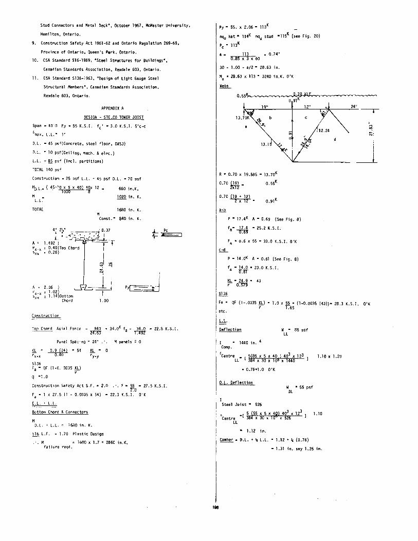
APPENDIX A
DESIGN - STELCO TOWER JOIST
Span • 40'0 Fy • 55 K.S.I. fc' • 3.0 K.S.I. 5'c-c
6max. L.L." 1"
D.L. • 45 psf(Concrete, steel floor, OWSJ)
D.L. • 10 psf(Ceiling, mech. & elec.)
L.L. • !!§. psf (Incl. partitions)
TOTAL 140 psf
Construction - 25 psf L.L. • 45 psf O.L. • 70 psf
f10.l • ~10_ X 5 X 40) 40x 12 • - 1000 8
M • L. L.
TOTAl M
660 in.K.
1020 in. K.
1680 in. K.
Canst. • 840 in. K.
4~ 2f _______ __J o. 37 , I ..,• .• • • • .: , 'l:l
J. -- • .i " • ' ; rf. 1.492 ) - -----=t = ~.40)Top Chord ! • o.26) I
~I ~
.L Pc
t-~
I I
--+· Py( -=.:c- • J A • 2.06 ) r x-x 1. 02) sxx 1.14)Bottom
Chord 1.00
Construction
Top Chord Axial Force = 840 • 34.0K fa= 34.0 • 22.8 K.S.I. 2'm ~
Panel Spacing • 24" . ·. M panels : 0
Sl36
0.9 (24) - 54 --o.4lf'""
Fa • QF (1-0. 0035 _ISh_) r
Q "1 .0
_ISh_ • 0 ry-y
Construction Safety Act S.F. • 2.0 .·. F • 55 • 27.5 K.S.I. 2.0
Fa • x 27.5 (1 - 0.0035 x 54) • 22.3 K.S.I. O'K
D.l. ' L .L.
Bottom Chord & Connectors
M D.L. + L.L. • 1680 in. K.
lli L.F. • 1.70 Plastic Design
• • M 1680 X 1.7 = 2860 in.K • failure reqd.
Py" 55. x 2.06 • 113K
nqu hat • 114K nqu stud •115K (see Fig. 20)
Pc • 113K
a • 113 • 0.74" 0.85 X J X 60
30 - 1.00 - a/2 • 28.63 in.
M • 28.63 x 113" 3240 in.K. D'K u
0.55~~~ ll 91K
t 19" 12" 24" -.
13.70K ~ c
·..v.
13.1
R • 0.70 x 19.585 • 13.70K
0.70 00-0.70 (19 + 12)
"'2'XT2.
P • 17.4K A • 0.69 (See Fig. 8)
fa· 17.4 • 25.2 K.S.I. ~
Fa • o.6 x 55 • 33.0 K.S.I. O'K
£.:.!!__
P • 14 .OK A • 0.61 (See Fig. 8}
fa • 14.0 • 23.0 K.S.I. Q.bT
KL • 24.9 • 43 ;:- 0-:-ID"
ill§_
d
~,
"'·
_l
Fa • QF (1-.0035 _ISh_) • 1.0 x 55 • (1-0.0035 (43))• 28.3 K.S.I. O'K r 1.65
etc.
I L.L.
~lection w • 85 psf LL
I I • 1440 in. Comp.
°Centre • [ 5(85 x 5 x 40 ) 403 x 123 ll 384 X 30 X 1 06 X l 440
1.10 X 1.20
• 0.76•1.0 O'K
D.L. Deflection W • 55 psf
DL
I Steel Joist • 526
0 5(55x5x4Ql403 xl23 Centre • 1 384 x 30 x 1 0 x 526
1.10
LL
• 1.12 in.
Camber • D.L. + '< L.L. • 1.12 + '< (0.76)
• 1.31 in. say 1.25 in.
1116
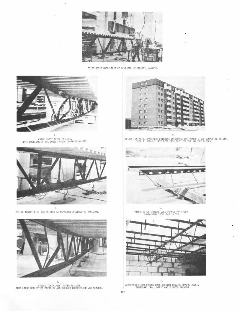
l.
) . I
CSICC JOIST UNDER TEST AT MCMASTER UNIVERSITY, HAMILTON
2.
CSICC JOIST AFTER FAILURE. NOTE BUCKLING OF THE DOUBLE ANGLE COMPRESSION WEB.
3.
STELCO TOWER JOIST OUR! NG TEST AT MCMASTER UNIVERSITY, HAMIL TON.
4.
STELCO TOWER JOIST AFTER FAILURE. NOTE LARGE DEFLECTION CAPACITY AND BUCKLED COMPRESSION WEB MEMBERS .
197
5.
OTTAWA, ONTARIO, APARTMENT BUILDING INCORPORATING HAMBRO D- 500 COMPOSITE JOISTS. SPECIAL DETAILS HAVE BEEN DEVELOPED FOR THE BALCONY FLOORS.
6.
HAMBRO JOIST SHOWING COLD FORMED TOP CHORD CONTAINING "ROLL BAR" SLOTS.
7.
1
APARTMENT FLOOR DURING CONSTRUCTION SHOWING HAMBRO JOIST, TEMPORARY "ROLL BARS" AND PL YWOOO FORMING.
I