Embed Size (px)
Citation preview
© 2016 Eaton Corporation. All rights reserved.
ANSI Standard C37.20.7: Arc Resistant Switchgear and Impact on Electrical
Workplace Safety
Western Electrical Mining Association ConferenceGillette, WY – May 24-26, 2016
David B. DurocherGlobal Industry ManagerMining, Metals & Minerals
Eaton CorporationWilsonville OR USA
May, 2016
2 2
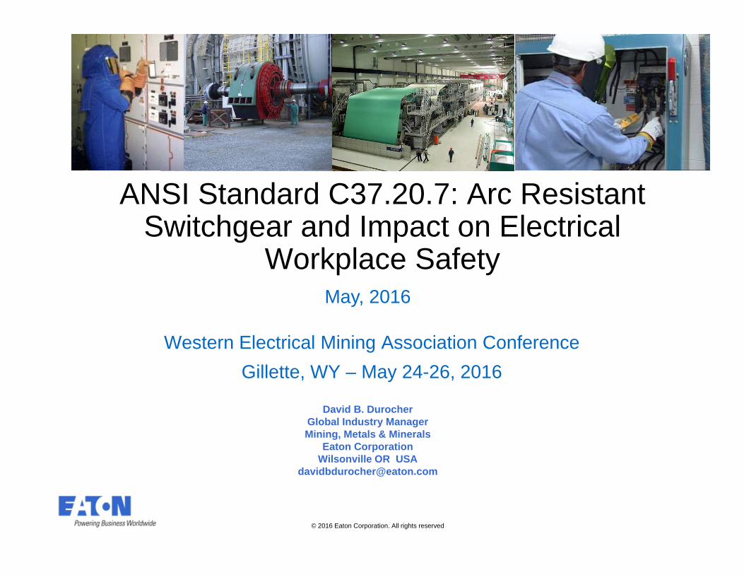
Short Infomercial – IEEE IASIEEE Industry Applications Society: Mining Industry Committee
Meeting in the fall at the IAS Annual Meeting
Typically two sessions of papers (one day)
Perhaps consider a WMEA co-located event in the future
3 3
OverviewWhat you will learn from today’s session?
Review arc flash events and electrical workplace safety standards
Become familiar with the ANSI/IEEE Standard C37.20.7
Understand the differences between arc-resistant switchgear and non arc-resistant switchgear
Understand the testing requirements for arc-resistant switchgear
Overview relative costs of standard versus arc-resistant switchgear
Comparing other technologies available that reduce arc flash energy
Application considerations in determining what should be specified for process industries
4 4
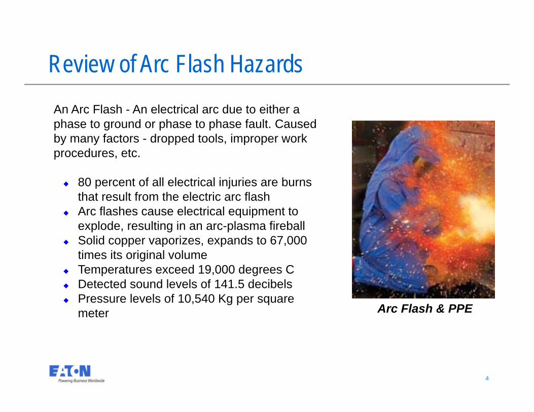
Arc Flash & PPE
Review of Arc Flash HazardsAn Arc Flash - An electrical arc due to either a phase to ground or phase to phase fault. Caused by many factors - dropped tools, improper work procedures, etc.
80 percent of all electrical injuries are burns that result from the electric arc flash
Arc flashes cause electrical equipment to explode, resulting in an arc-plasma fireball
Solid copper vaporizes, expands to 67,000 times its original volume
Temperatures exceed 19,000 degrees C Detected sound levels of 141.5 decibels Pressure levels of 10,540 Kg per square
meter
5 5
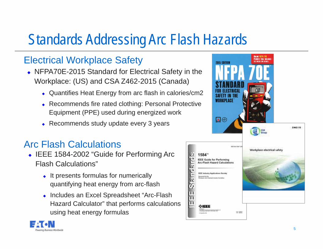
NFPA70E-2015 Standard for Electrical Safety in the Workplace: (US) and CSA Z462-2015 (Canada)
Quantifies Heat Energy from arc flash in calories/cm2
Recommends fire rated clothing: Personal Protective Equipment (PPE) used during energized work
Recommends study update every 3 years
Standards Addressing Arc Flash HazardsElectrical Workplace Safety
Arc Flash Calculations IEEE 1584-2002 “Guide for Performing Arc
Flash Calculations” It presents formulas for numerically
quantifying heat energy from arc-flash
Includes an Excel Spreadsheet “Arc-Flash Hazard Calculator” that performs calculations using heat energy formulas
6 6
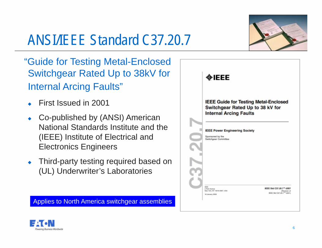
ANSI/IEEE Standard C37.20.7“Guide for Testing Metal-Enclosed Switchgear Rated Up to 38kV for Internal Arcing Faults” First Issued in 2001
Co-published by (ANSI) American National Standards Institute and the (IEEE) Institute of Electrical and Electronics Engineers
Third-party testing required based on (UL) Underwriter’s Laboratories
Applies to North America switchgear assemblies
7 7
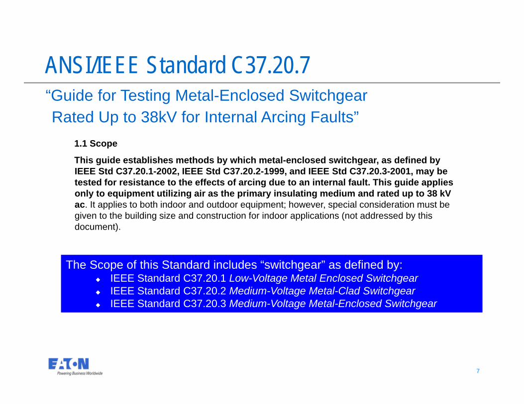
“Guide for Testing Metal-Enclosed Switchgear Rated Up to 38kV for Internal Arcing Faults”
The Scope of this Standard includes “switchgear” as defined by: IEEE Standard C37.20.1 Low-Voltage Metal Enclosed Switchgear IEEE Standard C37.20.2 Medium-Voltage Metal-Clad Switchgear IEEE Standard C37.20.3 Medium-Voltage Metal-Enclosed Switchgear
ANSI/IEEE Standard C37.20.7
1.1 Scope
This guide establishes methods by which metal-enclosed switchgear, as defined by IEEE Std C37.20.1-2002, IEEE Std C37.20.2-1999, and IEEE Std C37.20.3-2001, may be tested for resistance to the effects of arcing due to an internal fault. This guide applies only to equipment utilizing air as the primary insulating medium and rated up to 38 kV ac. It applies to both indoor and outdoor equipment; however, special consideration must be given to the building size and construction for indoor applications (not addressed by this document).
8 8
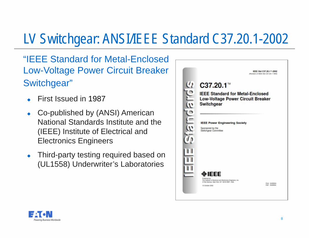
LV Switchgear: ANSI/IEEE Standard C37.20.1-2002“IEEE Standard for Metal-EnclosedLow-Voltage Power Circuit BreakerSwitchgear” First Issued in 1987
Co-published by (ANSI) American National Standards Institute and the (IEEE) Institute of Electrical and Electronics Engineers
Third-party testing required based on (UL1558) Underwriter’s Laboratories
9 9
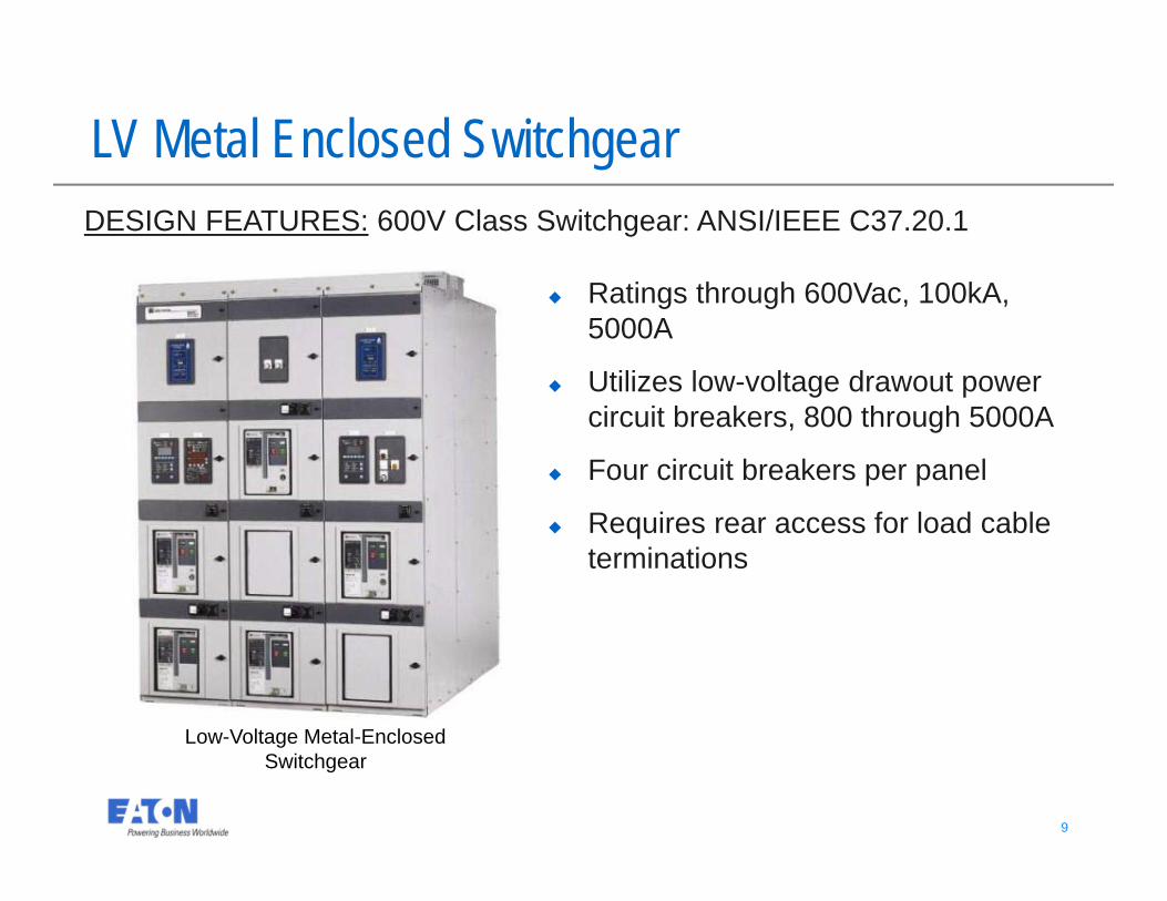
LV Metal Enclosed Switchgear
Low-Voltage Metal-Enclosed Switchgear
DESIGN FEATURES: 600V Class Switchgear: ANSI/IEEE C37.20.1
Ratings through 600Vac, 100kA, 5000A
Utilizes low-voltage drawout power circuit breakers, 800 through 5000A
Four circuit breakers per panel
Requires rear access for load cable terminations
10 10
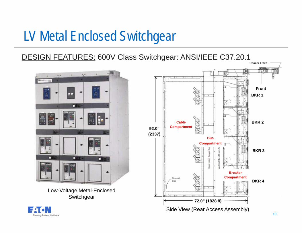
LV Metal Enclosed Switchgear
Low-Voltage Metal-Enclosed Switchgear
72.0” (1828.8)
92.0” (2337)
Cable Compartment
BusCompartment
Breaker Compartment
Breaker Lifter
Front
Side View (Rear Access Assembly)
BKR 1
BKR 3
BKR 4
BKR 2
DESIGN FEATURES: 600V Class Switchgear: ANSI/IEEE C37.20.1
11 11
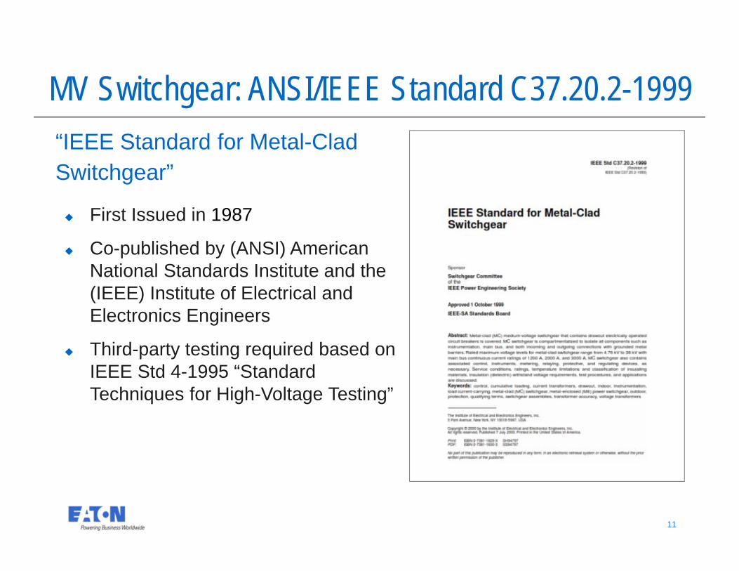
MV Switchgear: ANSI/IEEE Standard C37.20.2-1999“IEEE Standard for Metal-CladSwitchgear”
First Issued in 1987
Co-published by (ANSI) American National Standards Institute and the (IEEE) Institute of Electrical and Electronics Engineers
Third-party testing required based on IEEE Std 4-1995 “Standard Techniques for High-Voltage Testing”
12 12
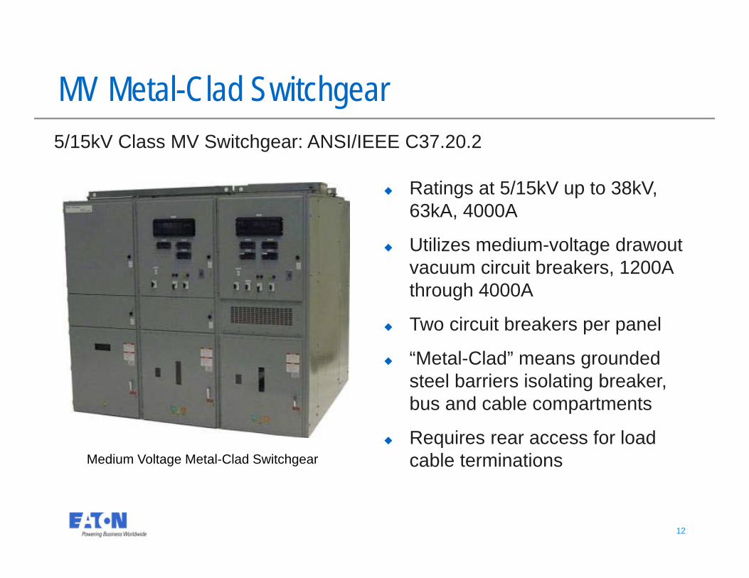
Medium Voltage Metal-Clad Switchgear
MV Metal-Clad Switchgear5/15kV Class MV Switchgear: ANSI/IEEE C37.20.2
Ratings at 5/15kV up to 38kV, 63kA, 4000A
Utilizes medium-voltage drawoutvacuum circuit breakers, 1200A through 4000A
Two circuit breakers per panel
“Metal-Clad” means grounded steel barriers isolating breaker, bus and cable compartments
Requires rear access for load cable terminations
13 13
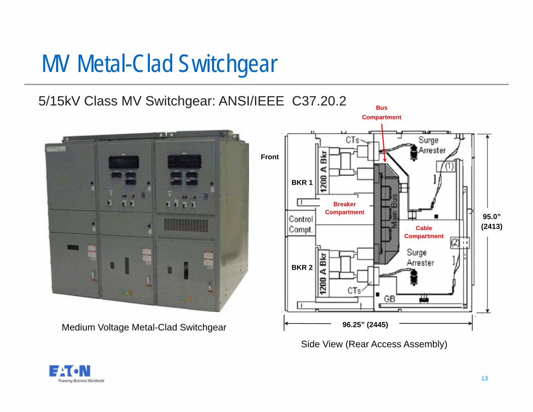
95.0” (2413)
MV Metal-Clad Switchgear
96.25” (2445)
Side View (Rear Access Assembly)
5/15kV Class MV Switchgear: ANSI/IEEE C37.20.2
Front
BKR 1
BKR 2
Medium Voltage Metal-Clad Switchgear
Cable Compartment
BusCompartment
Breaker Compartment
14 14
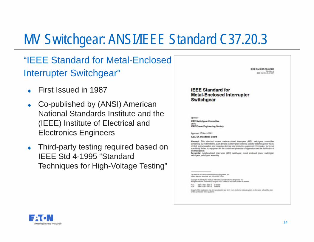
MV Switchgear: ANSI/IEEE Standard C37.20.3“IEEE Standard for Metal-EnclosedInterrupter Switchgear”
First Issued in 1987
Co-published by (ANSI) American National Standards Institute and the (IEEE) Institute of Electrical and Electronics Engineers
Third-party testing required based on IEEE Std 4-1995 “Standard Techniques for High-Voltage Testing”
15 15
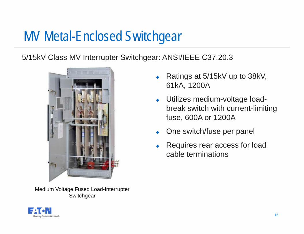
Medium Voltage Fused Load-Interrupter Switchgear
MV Metal-Enclosed Switchgear5/15kV Class MV Interrupter Switchgear: ANSI/IEEE C37.20.3
Ratings at 5/15kV up to 38kV, 61kA, 1200A
Utilizes medium-voltage load-break switch with current-limiting fuse, 600A or 1200A
One switch/fuse per panel
Requires rear access for load cable terminations
16 16
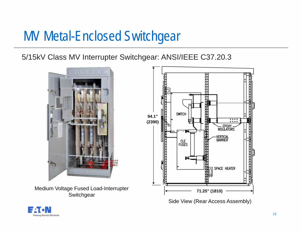
94.1” (2390)
Medium Voltage Fused Load-Interrupter Switchgear
MV Metal-Enclosed Switchgear5/15kV Class MV Interrupter Switchgear: ANSI/IEEE C37.20.3
71.25” (1810)
Side View (Rear Access Assembly)
17 17
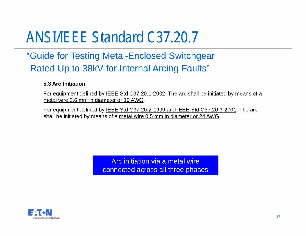
ANSI/IEEE Standard C37.20.7“Guide for Testing Metal-Enclosed Switchgear Rated Up to 38kV for Internal Arcing Faults”
5.3 Arc Initiation
For equipment defined by IEEE Std C37.20.1-2002: The arc shall be initiated by means of a metal wire 2.6 mm in diameter or 10 AWG.
For equipment defined by IEEE Std C37.20.2-1999 and IEEE Std C37.20.3-2001: The arc shall be initiated by means of a metal wire 0.5 mm in diameter or 24 AWG.
Arc initiation via a metal wire connected across all three phases
18 18
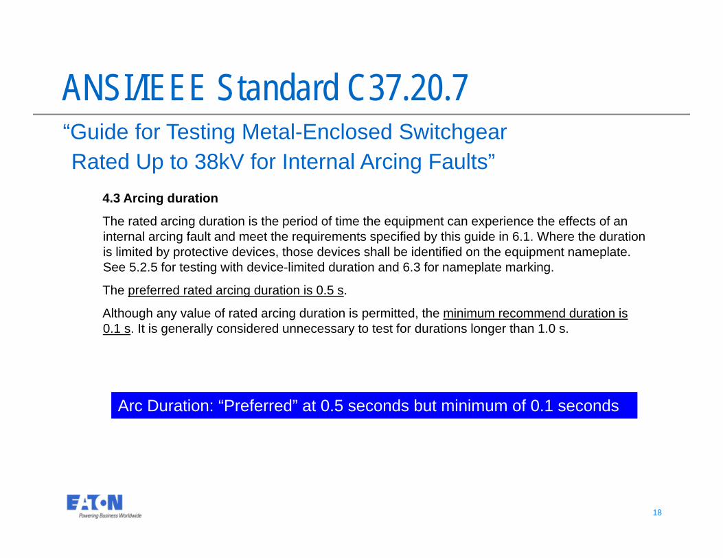
ANSI/IEEE Standard C37.20.7“Guide for Testing Metal-Enclosed Switchgear Rated Up to 38kV for Internal Arcing Faults”
4.3 Arcing duration
The rated arcing duration is the period of time the equipment can experience the effects of an internal arcing fault and meet the requirements specified by this guide in 6.1. Where the duration is limited by protective devices, those devices shall be identified on the equipment nameplate. See 5.2.5 for testing with device-limited duration and 6.3 for nameplate marking.
The preferred rated arcing duration is 0.5 s.
Although any value of rated arcing duration is permitted, the minimum recommend duration is 0.1 s. It is generally considered unnecessary to test for durations longer than 1.0 s.
Arc Duration: “Preferred” at 0.5 seconds but minimum of 0.1 seconds
19 19
ANSI/IEEE Standard C37.20.7“Guide for Testing Metal-Enclosed Switchgear Rated Up to 38kV for Internal Arcing Faults”
4.1 Accessibility type
A distinction is made between two levels of accessibility to switchgear assemblies. These levels correspond directly to the indicator placement given in 5.4.2.
Type 1 - Switchgear with arc-resistant designs or features at the freely accessible front of the equipment only.
Type 2 - Switchgear with arc-resistant designs or features at the freely accessible exterior front, back, and sides) of the equipment only.
“Type” designations define arc protection from the front of the switchgear only (Type 1) or from all sides (Type 2)
20 20
ANSI/IEEE Standard C37.20.7“Guide for Testing Metal-Enclosed Switchgear Rated Up to 38kV for Internal Arcing Faults”
A.2 Suffix “B”
This suffix is designated for equipment where normal operation of the equipment involves opening the door or cover of compartments specifically identified as low-voltage control or instrumentation compartments.
A.3 Suffix “C”
This suffix is designated for equipment where isolation from the effects of an internal arcing fault is desired between all adjacent compartments within a switchgear assembly.
A.4 Suffix “D”
This suffix is designated for equipment specifically designed for installations where some external surfaces of the equipment are inaccessible and no need exists to use a Type 2 design.
“Suffix” categories define arc performance for control compartments and between vertical sections
21 21
ANSI/IEEE Standard C37.20.7“Guide for Testing Metal-Enclosed Switchgear Rated Up to 38kV for Internal Arcing Faults”
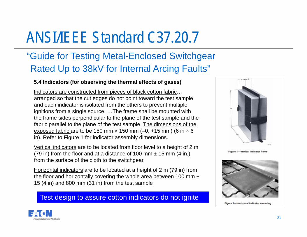
5.4 Indicators (for observing the thermal effects of gases)
Indicators are constructed from pieces of black cotton fabric…arranged so that the cut edges do not point toward the test sample and each indicator is isolated from the others to prevent multiple ignitions from a single source. …The frame shall be mounted with the frame sides perpendicular to the plane of the test sample and the fabric parallel to the plane of the test sample. The dimensions of the exposed fabric are to be 150 mm × 150 mm (–0, +15 mm) (6 in × 6 in). Refer to Figure 1 for indicator assembly dimensions.
Vertical indicators are to be located from floor level to a height of 2 m (79 in) from the floor and at a distance of 100 mm ± 15 mm (4 in.) from the surface of the cloth to the switchgear.
Horizontal indicators are to be located at a height of 2 m (79 in) from the floor and horizontally covering the whole area between 100 mm ±15 (4 in) and 800 mm (31 in) from the test sample
Test design to assure cotton indicators do not ignite
22 22
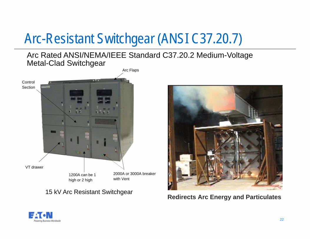
Redirects Arc Energy and Particulates
Arc-Resistant Switchgear (ANSI C37.20.7)
15 kV Arc Resistant Switchgear
Arc Rated ANSI/NEMA/IEEE Standard C37.20.2 Medium-Voltage Metal-Clad Switchgear
Arc Flaps
2000A or 3000A breaker with Vent
1200A can be 1 high or 2 high
ControlSection
VT drawer
23 23
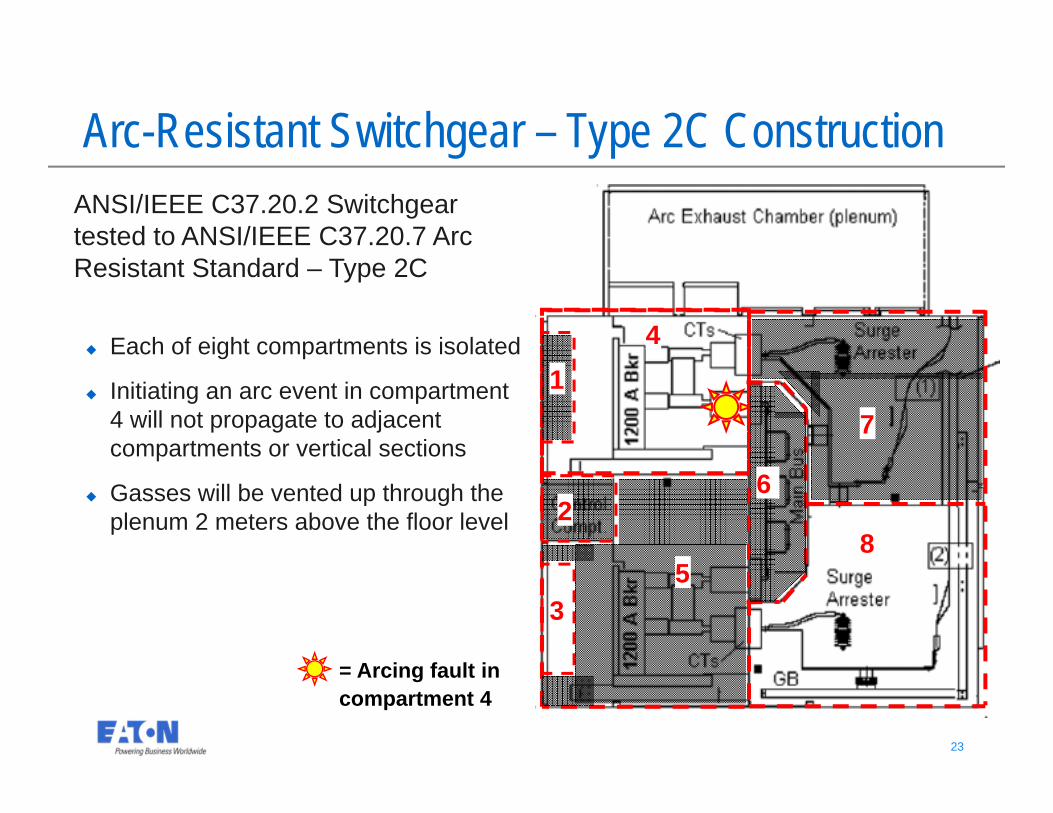
= Arcing fault in compartment 4
41
2
35
6
8
7
Arc-Resistant Switchgear – Type 2C ConstructionANSI/IEEE C37.20.2 Switchgear tested to ANSI/IEEE C37.20.7 Arc Resistant Standard – Type 2C
Each of eight compartments is isolated
Initiating an arc event in compartment 4 will not propagate to adjacent compartments or vertical sections
Gasses will be vented up through the plenum 2 meters above the floor level
24 24
MV Metal Enclosed Motor Control Centers
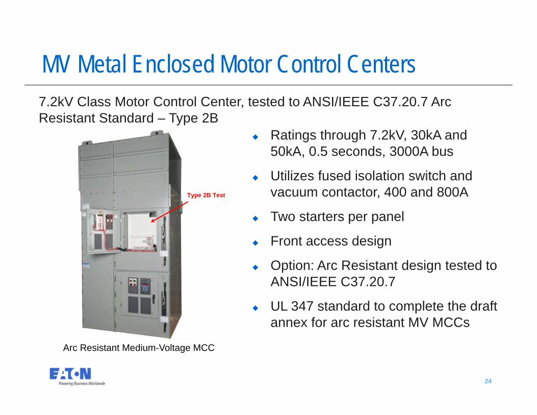
Arc Resistant Medium-Voltage MCC
7.2kV Class Motor Control Center, tested to ANSI/IEEE C37.20.7 Arc Resistant Standard – Type 2B
Ratings through 7.2kV, 30kA and 50kA, 0.5 seconds, 3000A bus
Utilizes fused isolation switch and vacuum contactor, 400 and 800A
Two starters per panel
Front access design
Option: Arc Resistant design tested to ANSI/IEEE C37.20.7
UL 347 standard to complete the draft annex for arc resistant MV MCCs
Type 2B Test
25 25
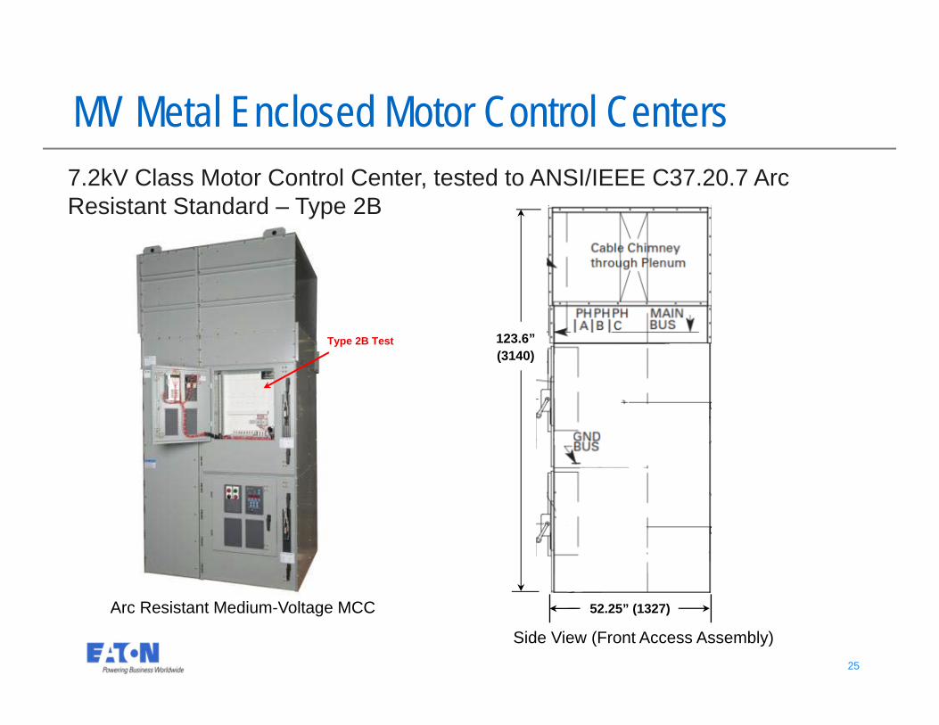
52.25” (1327)
123.6” (3140)
MV Metal Enclosed Motor Control Centers
Side View (Front Access Assembly)
Arc Resistant Medium-Voltage MCC
7.2kV Class Motor Control Center, tested to ANSI/IEEE C37.20.7 Arc Resistant Standard – Type 2B
Type 2B Test
26 26
LV Metal Enclosed Motor Control Centers
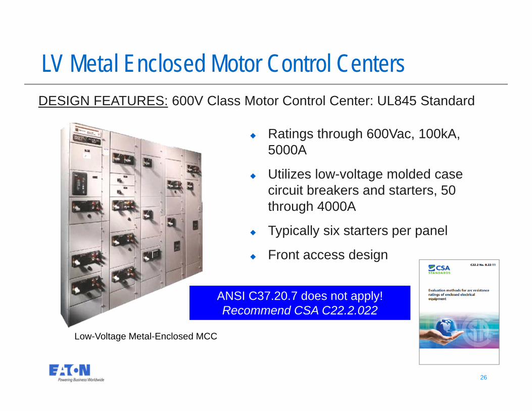
Low-Voltage Metal-Enclosed MCC
DESIGN FEATURES: 600V Class Motor Control Center: UL845 Standard
Ratings through 600Vac, 100kA, 5000A
Utilizes low-voltage molded case circuit breakers and starters, 50 through 4000A
Typically six starters per panel
Front access design
ANSI C37.20.7 does not apply!Recommend CSA C22.2.022
27 27
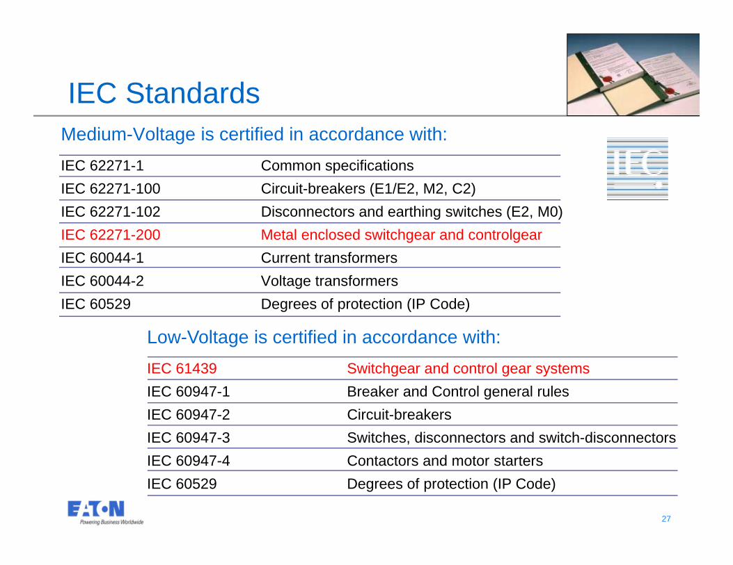
IEC StandardsMedium-Voltage is certified in accordance with:IEC 62271-1 Common specificationsIEC 62271-100 Circuit-breakers (E1/E2, M2, C2)IEC 62271-102 Disconnectors and earthing switches (E2, M0)IEC 62271-200 Metal enclosed switchgear and controlgearIEC 60044-1 Current transformersIEC 60044-2 Voltage transformersIEC 60529 Degrees of protection (IP Code)
Low-Voltage is certified in accordance with:IEC 61439 Switchgear and control gear systemsIEC 60947-1 Breaker and Control general rulesIEC 60947-2 Circuit-breakers IEC 60947-3 Switches, disconnectors and switch-disconnectorsIEC 60947-4 Contactors and motor startersIEC 60529 Degrees of protection (IP Code)
28 28
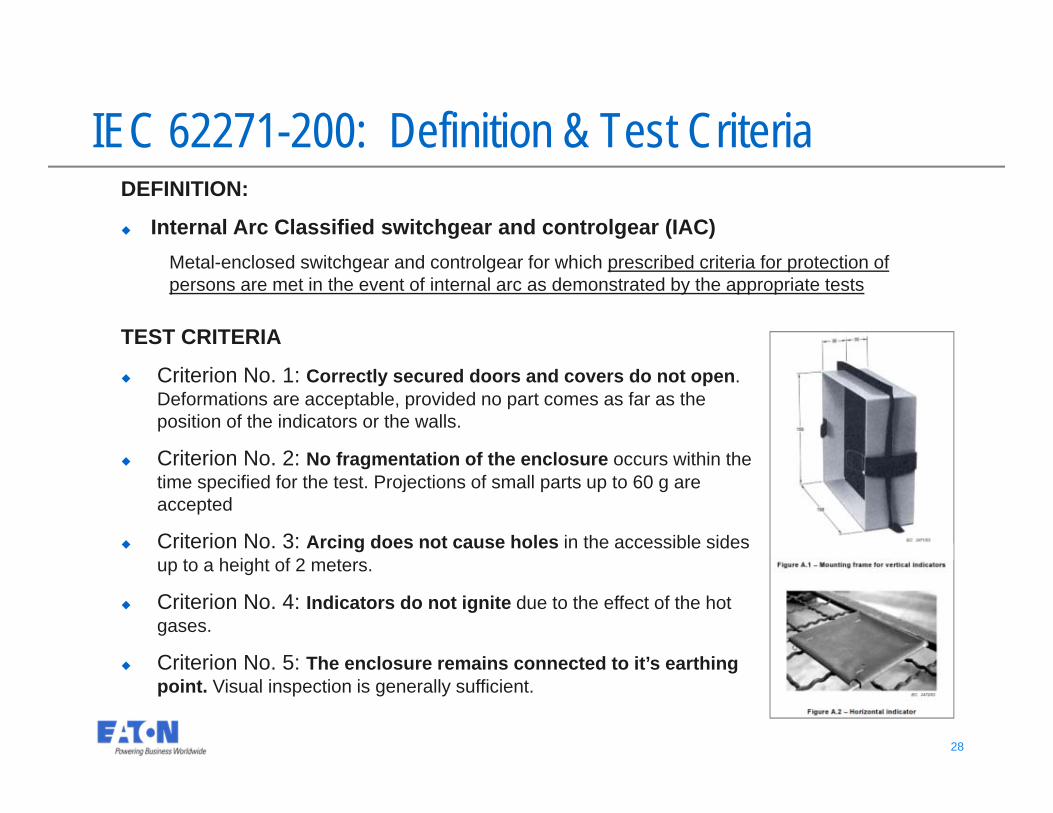
TEST CRITERIA
Criterion No. 1: Correctly secured doors and covers do not open. Deformations are acceptable, provided no part comes as far as the position of the indicators or the walls.
Criterion No. 2: No fragmentation of the enclosure occurs within the time specified for the test. Projections of small parts up to 60 g are accepted
Criterion No. 3: Arcing does not cause holes in the accessible sides up to a height of 2 meters.
Criterion No. 4: Indicators do not ignite due to the effect of the hot gases.
Criterion No. 5: The enclosure remains connected to it’s earthing point. Visual inspection is generally sufficient.
IEC 62271-200: Definition & Test CriteriaDEFINITION:
Internal Arc Classified switchgear and controlgear (IAC)Metal-enclosed switchgear and controlgear for which prescribed criteria for protection of persons are met in the event of internal arc as demonstrated by the appropriate tests
29 29
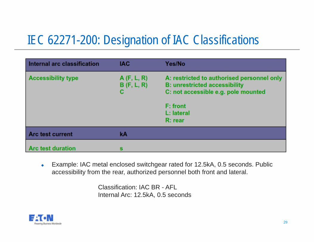
IEC 62271-200: Designation of IAC Classifications
Example: IAC metal enclosed switchgear rated for 12.5kA, 0.5 seconds. Public accessibility from the rear, authorized personnel both front and lateral.
Classification: IAC BR - AFL Internal Arc: 12.5kA, 0.5 seconds
30 30
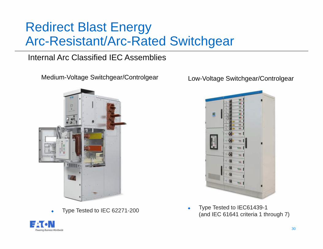
Internal Arc Classified IEC Assemblies
Type Tested to IEC61439-1 (and IEC 61641 criteria 1 through 7)
Type Tested to IEC 62271-200
Redirect Blast EnergyArc-Resistant/Arc-Rated Switchgear
Low-Voltage Switchgear/ControlgearMedium-Voltage Switchgear/Controlgear
31 31
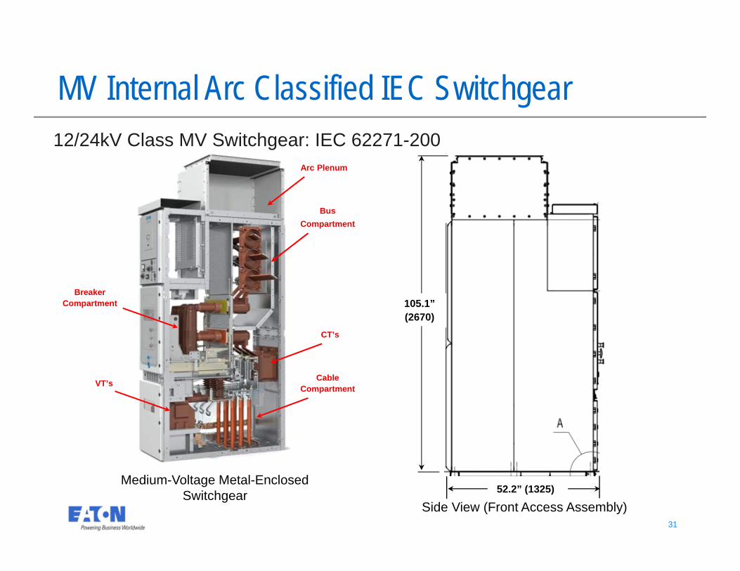
Medium-Voltage Metal-Enclosed Switchgear
Side View (Front Access Assembly)
105.1” (2670)
52.2” (1325)
MV Internal Arc Classified IEC Switchgear12/24kV Class MV Switchgear: IEC 62271-200
Cable Compartment
BusCompartment
Breaker Compartment
CT’s
VT’s
Arc Plenum
32 32
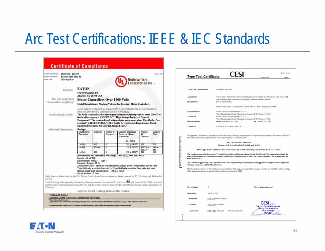
Arc Test Certifications: IEEE & IEC Standards
33 33
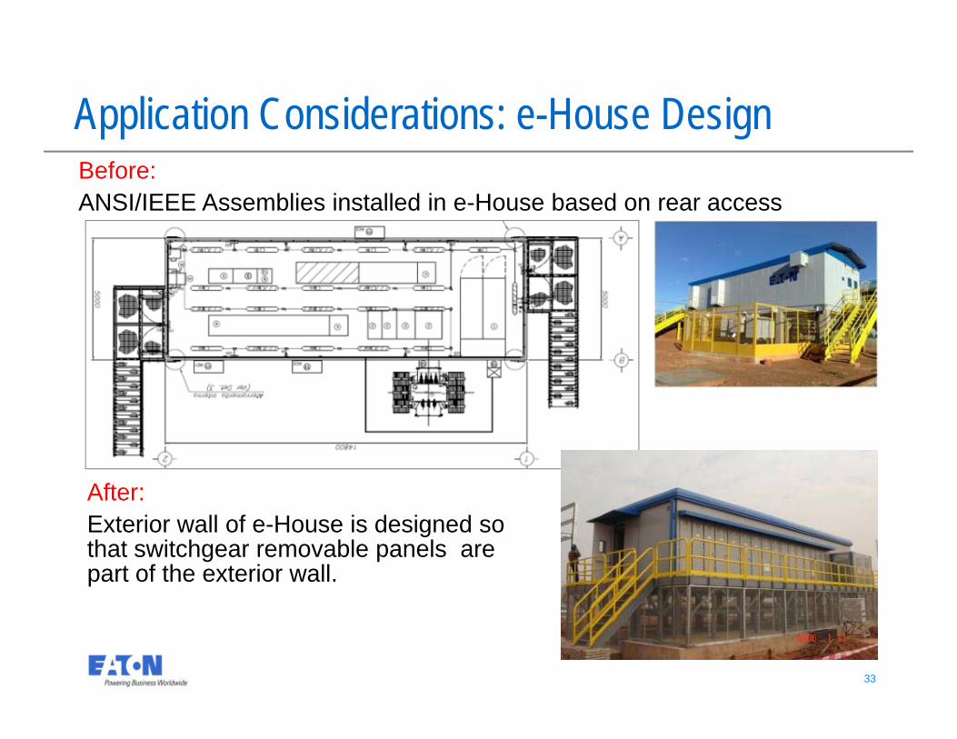
Application Considerations: e-House DesignBefore: ANSI/IEEE Assemblies installed in e-House based on rear access
After: Exterior wall of e-House is designed so that switchgear removable panels are part of the exterior wall.
34 34
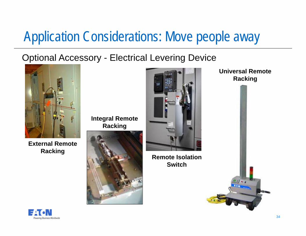
Optional Accessory - Electrical Levering Device
External Remote Racking
Integral Remote Racking
Application Considerations: Move people away
Remote Isolation Switch
Universal Remote Racking
35 35
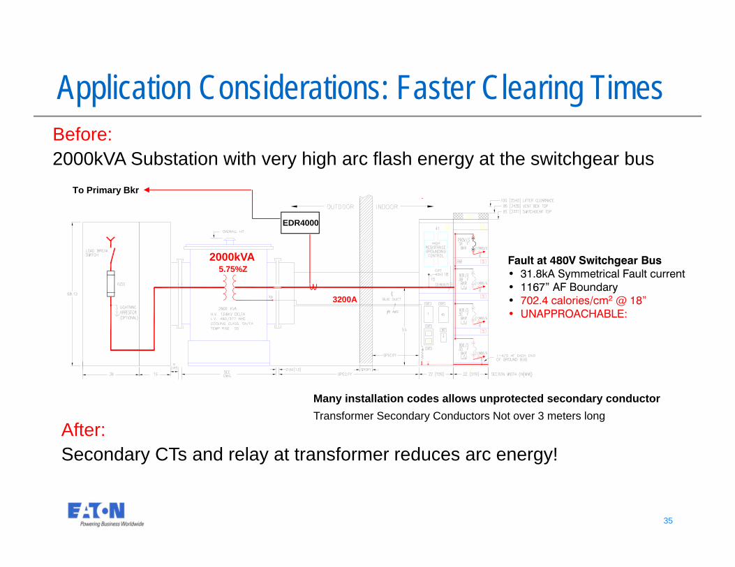
Many installation codes allows unprotected secondary conductorTransformer Secondary Conductors Not over 3 meters long
2000kVA5.75%Z
3200A
EDR4000
To Primary Bkr
Application Considerations: Faster Clearing Times
Fault at 480V Switchgear Bus• 31.8kA Symmetrical Fault current• 1167” AF Boundary• 702.4 calories/cm2 @ 18”• UNAPPROACHABLE:
Before: 2000kVA Substation with very high arc flash energy at the switchgear bus
After: Secondary CTs and relay at transformer reduces arc energy!
36 36
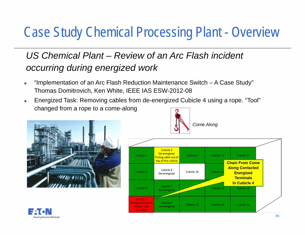
Case Study Chemical Processing Plant - Overview
“Implementation of an Arc Flash Reduction Maintenance Switch – A Case Study” Thomas Domitrovich, Ken White, IEEE IAS ESW-2012-08
Energized Task: Removing cables from de-energized Cubicle 4 using a rope. “Tool” changed from a rope to a come-along
US Chemical Plant – Review of an Arc Flash incident occurring during energized work
Come Along
37 37
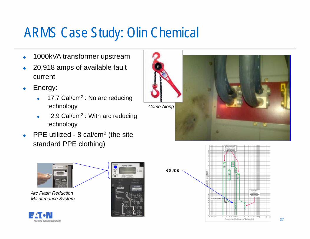
Arc Flash Reduction Maintenance System
ARMS Case Study: Olin Chemical
40 ms
1000kVA transformer upstream 20,918 amps of available fault
current Energy:
17.7 Cal/cm2 : No arc reducing technology
2.9 Cal/cm2 : With arc reducing technology
PPE utilized - 8 cal/cm2 (the site standard PPE clothing)
Come Along
38 38
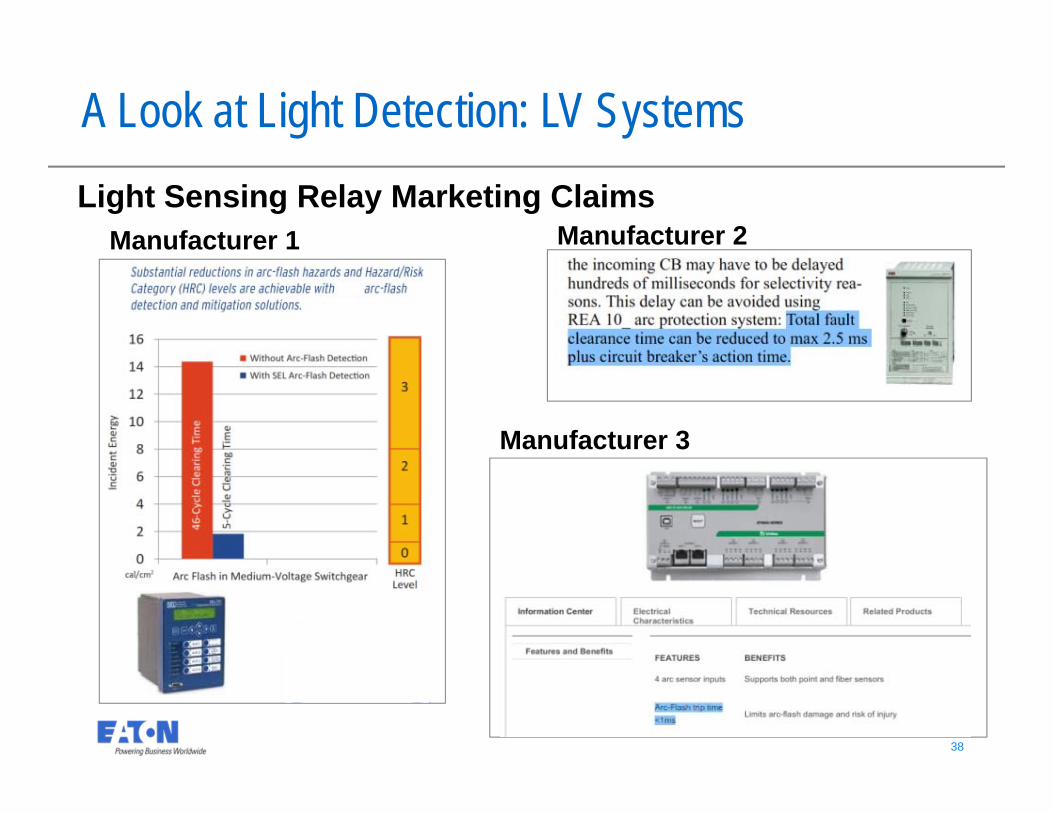
Light Sensing Relay Marketing ClaimsManufacturer 1 Manufacturer 2
Manufacturer 3
A Look at Light Detection: LV Systems
39 39
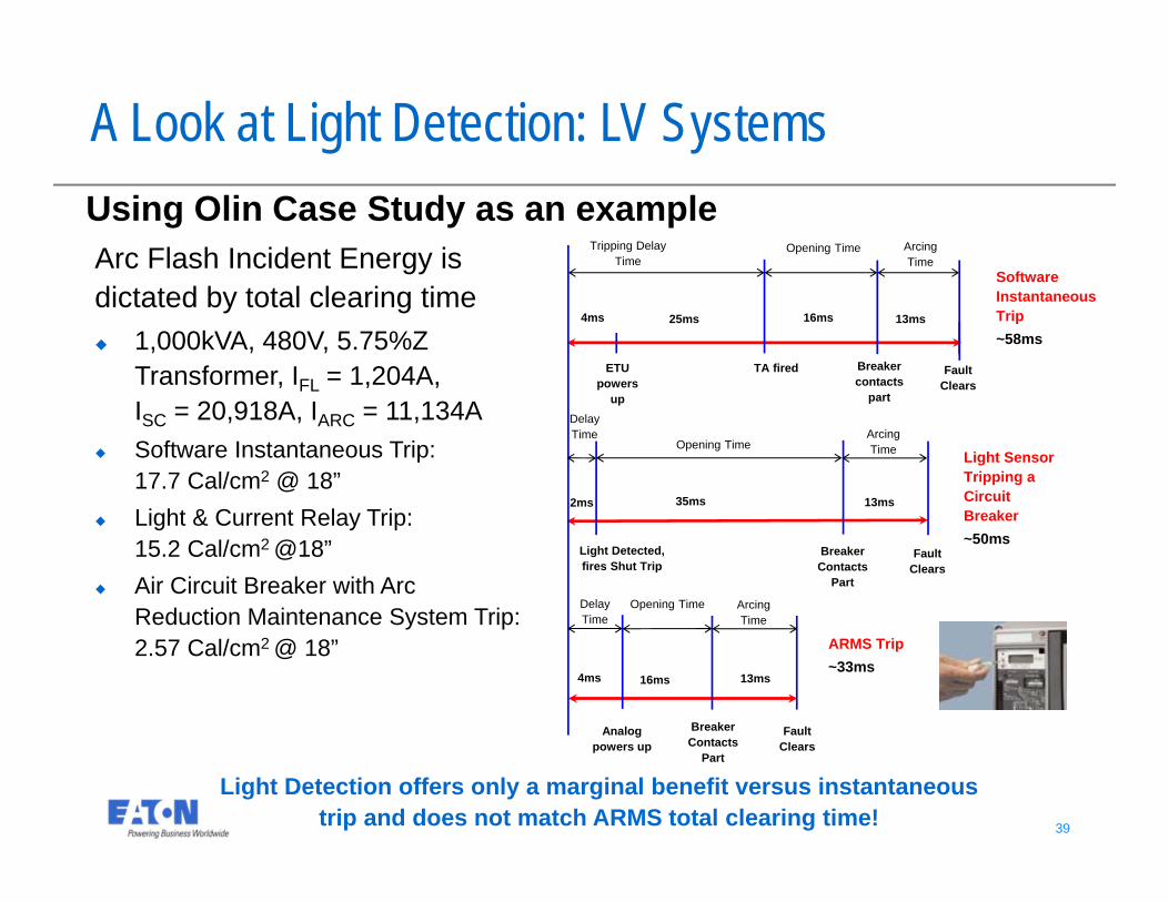
Arc Flash Incident Energy is dictated by total clearing time 1,000kVA, 480V, 5.75%Z
Transformer, IFL = 1,204A, ISC = 20,918A, IARC = 11,134A
Software Instantaneous Trip: 17.7 Cal/cm2 @ 18”
Light & Current Relay Trip: 15.2 Cal/cm2 @18”
Air Circuit Breaker with Arc Reduction Maintenance System Trip: 2.57 Cal/cm2 @ 18”
Light Detection offers only a marginal benefit versus instantaneous trip and does not match ARMS total clearing time!
A Look at Light Detection: LV Systems
Light Detected, fires Shut Trip
Breaker Contacts
Part
Fault Clears
Fault Clears
Fault Clears
Breaker Contacts
Part
Breaker contacts
part
ETU powers
up
TA fired
4ms
4ms
25ms 16ms 13ms
2ms 35ms 13ms
16ms 13ms
Analog powers up
Software Instantaneous Trip ~58ms
Light Sensor Tripping a Circuit Breaker ~50ms
ARMS Trip ~33ms
Tripping Delay Time
Opening Time Arcing Time
Opening Time Arcing Time
Delay Time
Opening TimeArcing Time
Delay Time
Using Olin Case Study as an example
40 40
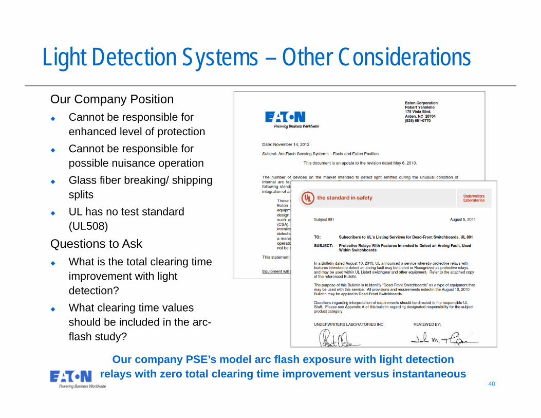
Light Detection Systems – Other Considerations
Questions to Ask What is the total clearing time
improvement with light detection?
What clearing time values should be included in the arc-flash study?
Our company PSE’s model arc flash exposure with light detection relays with zero total clearing time improvement versus instantaneous
Our Company Position Cannot be responsible for
enhanced level of protection Cannot be responsible for
possible nuisance operation Glass fiber breaking/ shipping
splits UL has no test standard
(UL508)
41 41
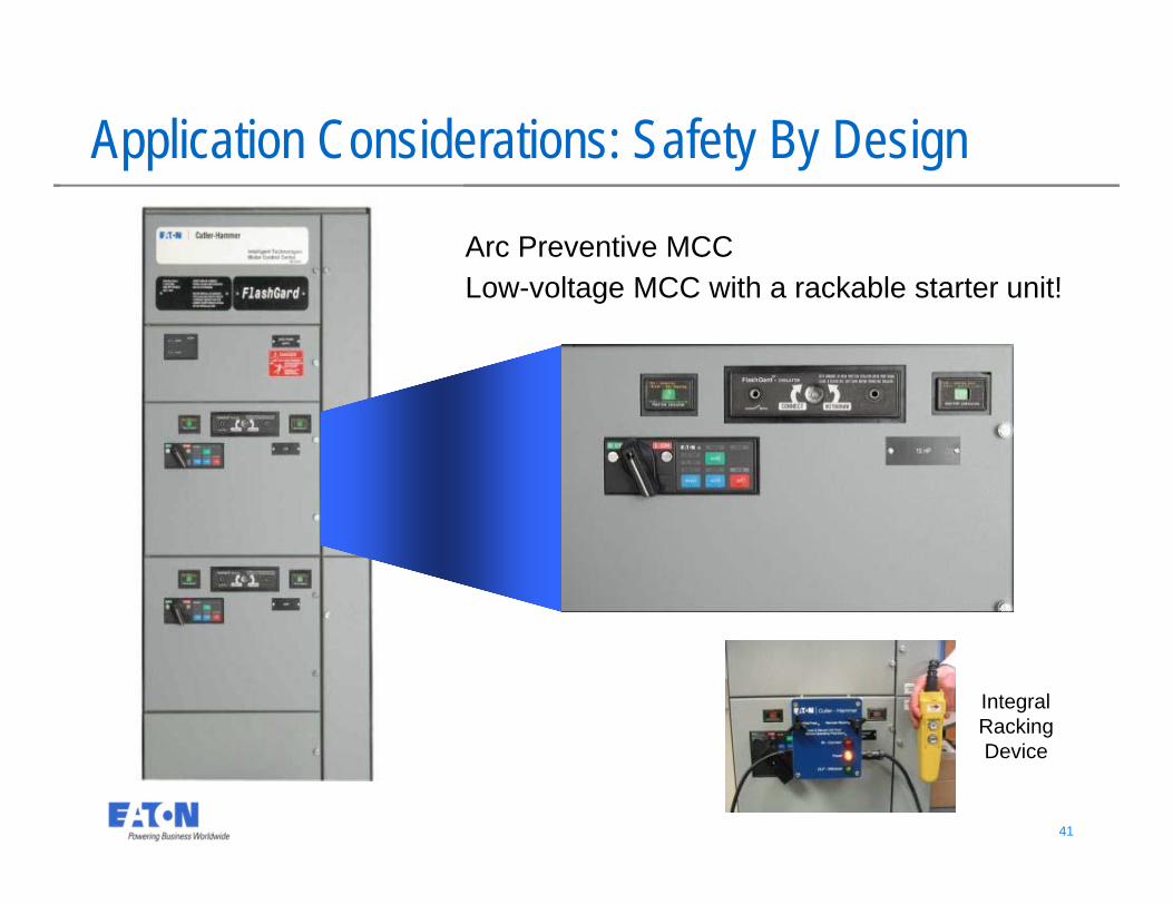
Arc Preventive MCCLow-voltage MCC with a rackable starter unit!
Application Considerations: Safety By Design
Integral Racking Device
42 42
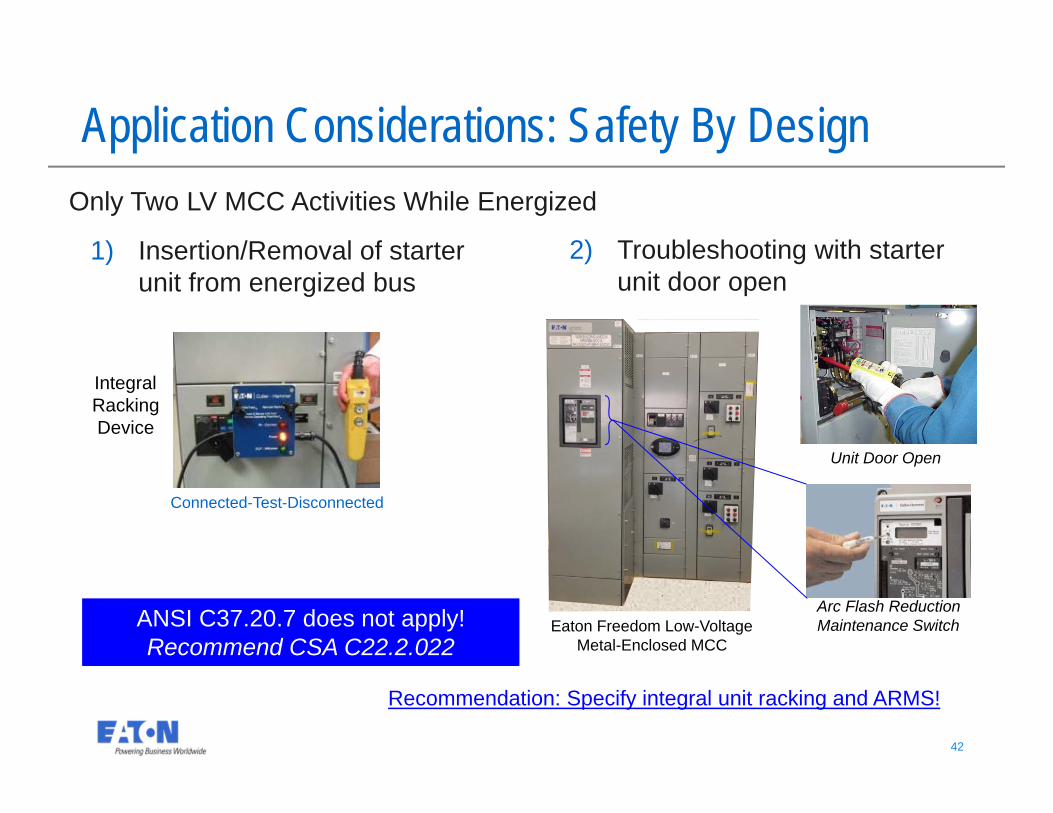
Eaton Freedom Low-Voltage Metal-Enclosed MCC
Only Two LV MCC Activities While Energized
Application Considerations: Safety By Design
Integral Racking Device
2) Troubleshooting with starter unit door open
Connected-Test-Disconnected
1) Insertion/Removal of starter unit from energized bus
Arc Flash Reduction Maintenance Switch
Unit Door Open
Recommendation: Specify integral unit racking and ARMS!
ANSI C37.20.7 does not apply!Recommend CSA C22.2.022
43 43
Conclusions ANSI/IEEE Standard C37.20.7 is a supplementary arc testing “add-
on” Standard for existing ANSI/IEEE low-voltage and medium-voltage switchgear and medium-voltage MCCs
Today, ANSI/IEEE Standard C37.20.7 does not apply for LV MCCs
IEC Standards include arc testing for both LV and MV switchgear and controlgear assemblies
Arc rated assemblies simply redirect the heat energy. Reducing the energy can only be accomplished by reducing the source MVA, moving people further away or reducing the total clearing time
It is important to understand the Standards and the product designs manufactured to these Standards in selecting the right technology for your mine application
© 2016 Eaton Corporation. All rights reserved.
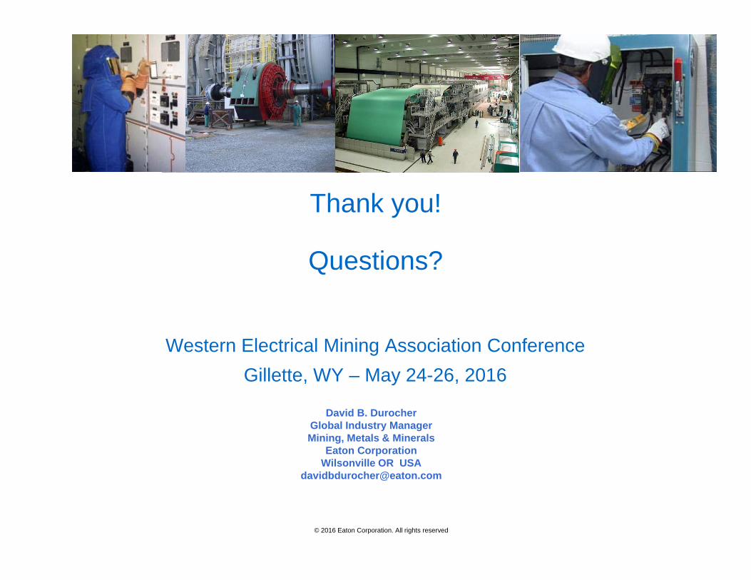
Thank you!
Questions?
Western Electrical Mining Association ConferenceGillette, WY – May 24-26, 2016
David B. DurocherGlobal Industry ManagerMining, Metals & Minerals
Eaton CorporationWilsonville OR USA