Embed Size (px)
Citation preview
TECHNICAL SPECIFICATIONS OF NIT FOR ADDITAIONAL COOLING TOWER CELLS NFVP/CTC-2013-C1 0
PROJECT : ADDITAIONAL COOLING TOWER CELLS DOCUMENT NO. REV.
CLIENT : NFL VIJAIPUR Page 1 of 22
ANNEXURE C-1
ENGINEERING DESIGN BASIS CIVIL, STRUCTURAL & ALLIED WORKS
ENGINEERING DESIGN BASIS FOR
CIVIL,STRUCTURAL & ALLIED WORKS
NEW COOLING TOWER CELLS
NFVP/CTC-2013-C1 0
DOCUMENT NO. REV.
Page 2 of 22
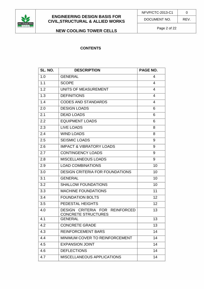
CONTENTS
SL. NO. DESCRIPTION PAGE NO. 1.0 GENERAL 4
1.1 SCOPE 4
1.2 UNITS OF MEASUREMENT 4
1.3 DEFINITIONS 4
1.4 CODES AND STANDARDS 4
2.0 DESIGN LOADS 6
2.1 DEAD LOADS 6
2.2 EQUIPMENT LOADS 6
2.3 LIVE LOADS 8
2.4 WIND LOADS 8
2.5 SEISMIC LOADS 9
2.6 IMPACT & VIBRATORY LOADS 9
2.7 CONTINGENCY LOADS 9
2.8 MISCELLANEOUS LOADS 9
2.9 LOAD COMBINATIONS 10
3.0 DESIGN CRITERIA FOR FOUNDATIONS 10
3.1 GENERAL 10
3.2 SHALLOW FOUNDATIONS 10
3.3 MACHINE FOUNDATIONS 11
3.4 FOUNDATION BOLTS 12
3.5 PEDESTAL HEIGHTS 12
4.0 DESIGN CRITERIA FOR REINFORCED CONCRETE STRUCTURES
13
4.1 GENERAL 13
4.2 CONCRETE GRADE 13
4.3 REINFORCEMENT BARS 14
4.4 MINIMUM COVER TO REINFORCEMENT 14
4.5 EXPANSION JOINT 14
4.6 DEFLECTIONS 14
4.7 MISCELLANEOUS APPLICATIONS 14

ENGINEERING DESIGN BASIS FOR
CIVIL,STRUCTURAL & ALLIED WORKS
NEW COOLING TOWER CELLS
NFVP/CTC-2013-C1 0
DOCUMENT NO. REV.
Page 3 of 22
5.0 DESIGN CRITERIA FOR STEEL STRUCTURES
15
5.1 GENERAL / DESIGN METHOD 15
5.2 EXPANSION JOINTS 16
5.3 STEEL GRADE 16
5.4 LIMITING PERMISSIBLE STRESSES 16
5.5 LIMITING DEFLECTION 17
5.6 MINIMUM THICKNESS 17
6.0 DESIGN REQUIREMENTS FOR SPECIFIC APPLICATIONS
18
6.1 PIPERACK 18
7.0 DESIGN CRITERIA GENERAL 20
7.1 SITE GRADING 20
7.2 ROADS 20
7.3 PAVING 20
7.4 STORM WATER DRAINAGE 21
ENGINEERING DESIGN BASIS FOR
CIVIL,STRUCTURAL & ALLIED WORKS
NEW COOLING TOWER CELLS
NFVP/CTC-2013-C1 0
DOCUMENT NO. REV.
Page 4 of 22
1.0 GENERAL
1.1 Scope
This engineering design basis defines the minimum design criteria that shall form the basis for carrying out detailed structural design and engineering of NEW Cooling tower cells structures and associate work as per scope of work. All data required in this regard shall be taken into consideration for acceptable, satisfactory and trouble-free engineering of the structures.
Compliance with this design basis and / or review of any of the contractor documents shall in no case relieve the contractor at the contractual obligations. All structures shall be designed for the satisfactory performance of the functions for which they are being constructed.
1.2 Units of Measurement
Units of measurement in design shall be in metric system.
1.3 Definitions
1. CCE Chief Controller of Explosives 2. TAC Tariff Advisory Committee 3. NFPA National Fire Protection Association 4. IS Indian Standards
1.4 Codes and Standards
The design shall be in accordance with established codes, sound engineering practices and shall conform to the statutory regulations applicable to the country.
The main codes and standards and statutory regulations considered as minimum requirements are as follows Latest revision of these shall be followed:
IS:456 Code of practice for plain & reinforced concrete
IS:800 Code of practice for general construction in steel
IS 801 Code of practice for use of cold formed light gauge steel structural members in general building construction.
IS:802 Code of practice for use of structural steel in overhead transmission line towers
IS:806 Code of practice for use of steel tubes in general building construction
IS:816 Code of practice for use of metal arc welding for general construction
IS:875 Code of practice for design loads
IS:1080 Code of practice for design & construction of shallow foundations on soil
IS:1161 Specification for steel tubes for structural purpose

ENGINEERING DESIGN BASIS FOR
CIVIL,STRUCTURAL & ALLIED WORKS
NEW COOLING TOWER CELLS
NFVP/CTC-2013-C1 0
DOCUMENT NO. REV.
Page 5 of 22
IS:1597 Code of practice for construction of stone masonry
IS:1838 Filters for expansion joints
IS:1893 Criteria for earth quake resistant design of structures
IS:1904 Code of practice for design and construction of foundations in soils, General requirements
IS:1905 Code of practice for structural use of un-reinforced masonry
IS:2185 Concrete masonry units
IS:2629 Recommended practice for hot dip galvanizing of iron and steel
IS:2633 Methods for testing uniformity of coating of zinc coated articles
IS:2911 Code of practice for design and construction of pile foundations
IS:2950 Code of practice for design & construction of raft foundations
IS:2974 Code of practice for design & construction of machine foundations
IS:4091 Code of practice for design and construction of foundation for transmission line tower and poles
IS:4326 Code of practice for earthquake resistant design and construction of buildings
IS:4925 Specification for Concrete Batching and Mixing Plant
IS:4991 Criteria for blast resistant design of structures for explosions above ground
IS:5249 Determination of dynamic properties of soil
IS:6403 Code of practice for determination of bearing capacity of shallow foundations
IS:6533 Code of practice for design and construction of steel chimneys
IS:6745 Method for determination of mass of zinc coating
IS:8009 Code practice for calculation of settlements of foundations
IS:8944 Chlorpyrifos emulsifiable concentrates
IS:9595 Recommendations for metal arc welding of carbon and carbon manganese steel
IS:11089 Code of practice for design and construction of ring foundation
IS:12118 Two parts polysulphide based sealant
IS:13920 Code of practice for ductile detailing of reinforced concrete structures subjected to seismic forces.
National Building Code
Factory Rules
ENGINEERING DESIGN BASIS FOR
CIVIL,STRUCTURAL & ALLIED WORKS
NEW COOLING TOWER CELLS
NFVP/CTC-2013-C1 0
DOCUMENT NO. REV.
Page 6 of 22
In case of any difference between Codal provision and this design basis, the stringent one should govern the design.
In case of any conflict / deviations amongst various documents, the order of precedence shall be as follows:
1. Statutory Regulations 2. Job Specifications 3. Engineering Design Basis 4. Standard Specifications
2.0 Design Loads
The following design loadings shall be considered:
1. Dead loads including self weight
2. Live load 3. Wind load 4. Seismic load 5. Equipment load 6. Dynamic load 7. Load from lifting appliances 8. Erection loads / maintenance loads 9. Thermal load 10. Earth pressure / Hydrostatic Loads 11. Any other load not mentioned above, but applicable
These loadings shall be applicable to all structures irrespective of the material employed for construction.
2.1 Dead Loads
Dead load shall comprise of the weight of all permanent construction including walls, fire proofing, floors, roofs, partitions, stairways and fixed services.
2.2 Equipment Loads
The empty / operating / test weight of process equipment including all fixtures, platforms, ladders and attached piping but excluding contents, shall be considered. If piping weight is not indicated separately or not included in the weight of the equipment, the same shall be taken as 10% of the weight of the equipment.
ENGINEERING DESIGN BASIS FOR
CIVIL,STRUCTURAL & ALLIED WORKS
NEW COOLING TOWER CELLS
NFVP/CTC-2013-C1 0
DOCUMENT NO. REV.
Page 7 of 22
2.2.1. Special Considerations
a. Bundle Pull
Bundle pull forces for different types of exchangers shall be taken as under:
a. Fixed type - Nil b. Kettle type - 0.30 × Bundle weight c. All other types - 0.86 × Bundle weight or 30 N/mm of diameter Whichever is greater
Total Bundles Pull shall be considered on fixed pedestal alone
b. Thermal Expansion
Horizontal force due to thermal expansion of horizontal vessels / exchangers shall be relieved by using slotted holes and slide plates and remaining force derived from the product of the sliding saddle ‘gravity load’ and the coefficient of friction shall be applied to each support. the coefficient of friction shall be taken as under:
a. teflon to teflon : 0.08 b. stainless steel to teflon : 0.10 c. steel to steel : 0.30 d. steel to concrete : 0.45
c. Non-Static Loading
Foundations and structures supporting vessels subject to surge loading, such as Deaerators shall be designed with sufficient stiffness and rigidity to resist a notional horizontal forces of 10% of those derived from the Vessel’s operating weight or the given surge load whichever is greater. The forces shall be applied at the vessel’s centre of gravity and act longitudinally or transversely. Consideration shall be given to bracing these structures.
The design of foundations and structures supporting agitated vessels, centrifuges, reactors and other variable load equipment shall take full account of all the loading data provided by the equipment vendors. Where no loads are available, consideration shall be given to applying force at 10% of operating weight. In addition, for dynamic effect loads will be increased by 50% of steam agitated equipment and 25% for mechanical agitated vessels.
Where two or more similar items of such equipment are supported on a common foundation or structure, the design must be based on the assumption that these items will resonate in phase.
2.2.2 Rotating Equipment

ENGINEERING DESIGN BASIS FOR
CIVIL,STRUCTURAL & ALLIED WORKS
NEW COOLING TOWER CELLS
NFVP/CTC-2013-C1 0
DOCUMENT NO. REV.
Page 8 of 22
Comprehensive loading data of mechanical equipment, such as, fans, blowers, pumps, compressors, D.G. Sets, turbines, motors engines etc., as furnished by the equipment vendor shall be considered.
2.3 Live Loads
Live loads shall, in general, be as per IS:875. However, the following minimum live loads shall be considered in the design of structures to account for maintenance and erection phases; if equipment layout / vendor drawings indicate loads of greater magnitude, the same shall be adopted.
1. Process Building / Technological Structure (Open / Enclosed type) Operating area - 5.0 kN/m² Maintenance area - 7.5 kN/m² Ground floor - 10.0 kN/m²
2. Compressor House/TG House Operating area - 7.5 kN/m² Maintenance area - 7.5 kN/m² Ground floor - 10.0 kN/m²
3. Service Platform Vessel / Tower - 3.0 kN/m² Isolated platform - 2.5 kN/m² (for valve operation) Access way - 2.5 kN/m² Cross over - 2.0 kN/m² Piperack walkways - 2.5 kN/m² Gantry girder walkway - 3.0 kN/m²
Upper floors - 4.0 kN/m² Ground floor - 5.0 kN/m²
4. Staircase Process Building - 5.0 kN/m² Technological structure - 5.0 kN/m² Office - 5.0 kN/m² Substation/Control Room - 3.0 kN/m² Laboratory - 4.0 kN/m² Service platform - 2.5 kN/m²
Loads on account of equipment and incidental loads shall be taken over and above the loads indicated in the table.
For all other buildings not covered in above Table, the imposed loads shall be taken as specified in IS:875 (Part II)
1 kN/m² allowance shall be made for services supported from below the floor.
Live load on various types of roofs shall be as per the requirements given in IS:875.
ENGINEERING DESIGN BASIS FOR
CIVIL,STRUCTURAL & ALLIED WORKS
NEW COOLING TOWER CELLS
NFVP/CTC-2013-C1 0
DOCUMENT NO. REV.
Page 9 of 22
2.4 Wind Loads
Wind loads for structural design shall be as per IS-875 (Part-3) except for switchyard structures and transmission towers for which IS:802 shall be applicable. Basic wind speed shall be 160 Km/hr. Definition of basic wind speed shall be peak gust velocity averaged over 3 second time interval at 10 m height above mean ground level with 50 years mean return period. The design life span of all structures, except temporary structures, and boundary wall shall be taken as 50 years. Life span of temporary structures and boundary wall can be lesser and shall be as per IS:875.
To account for surface area of piping, platforms and other attachments fixed to the equipment, the surface area of the equipment (vessel/column) exposed to wind shall be increased by 20% or as specified in the mechanical data sheets of the equipment.
2.5 Seismic Loads
Seismic loads shall be as per IS:1893 (Latest Revision).
2.6 Impact and Vibratory Loads
Structures subjected to impact or vibratory loads shall be designed as per the provision of IS:875 & IS:2974. Requirements for monorails and overhead cranes shall be as per IS:800, IS:875 or manufacturer’s data, whichever is more stringent.
2.7 Contingency Loads
2.7.1 RCC Structures
All floor slabs and beams shall be designed for a concentrated load of 10 KN acting simultaneously with the uniform live load, but not with actual concentrated loads from equipment, piping etc. This load shall be placed to result in maximum moment and / or maximum shear.
This load shall not be considered for the design of columns, foundations and in overall frame analysis. For floor slabs, the load shall be considered to be distributed over an area of 0.75 m x 0.75 m.
2.7.2 Structural Steel
For process plants, the following contingency additional loading shall be applied to individual beam elements, these shall be applied as point loads to produce worst shear and bending stresses:
1. Platform Walkways 3 kN
2. Secondary Floor Trimmers 5 kN
3. Primary / Grid beams 10 kN
2.8 Miscellaneous Loads
Apart from the specified live loads, possible overloading during construction / hydro-test maintenance / erection shall also be considered in the design Job specifications and shall also be referred to, for any specific loading.

ENGINEERING DESIGN BASIS FOR
CIVIL,STRUCTURAL & ALLIED WORKS
NEW COOLING TOWER CELLS
NFVP/CTC-2013-C1 0
DOCUMENT NO. REV.
Page 10 of 22
Hydrostatic pressure shall be adequately accounted for, in the design of structures, below ground water table.
All the handrails, parapets, parapet walls, balustrades shall be designed for horizontal load mentioned in Table 3 of IS-875 (Part-2).
2.9 Load Combinations Structure & its member shall be designed for worst combination of the above loads.
3.0 DESIGN CRITERIA FOR FOUNDATIONS
3.1 General
Foundation sizing shall be based on working loads without any factor.
All major foundation may be placed at a depth of 1.5-2.0 meters below ground level with net safe bearing capacity of 300-450 KN/m². Ordinary foundation may be placed at a depth of 1.0-1.5 meters below ground level with net safe bearing capacity of 150-200 KN/m².
3.2 Shallow Foundations
3.2.1 For gravity loading, allowable net bearing capacity of soil shall be based on the following settlement criteria:
Foundation Type Allowable Settlement(mm)
− Foundations in unit areas, utility areas and Foundations for plant buildings including substation, Compressor house, control room, technological structures
25
− Machine foundations and critical equipment with interconnected piping
25
− Foundations supporting non-plant buildings 40
3.2.2 For transient loadings, such as wind / seismic, allowable net bearing capacity based on shear criteria may be considered.
3.2.3 For load combinations including wind/Earthquake, the Safe Soil Bearing Pressure may be increased by 25%.
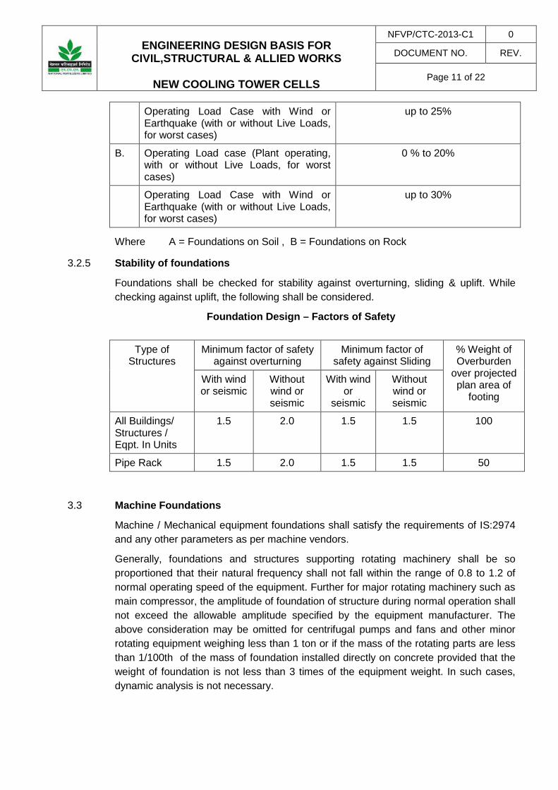
3.2.4 Allowable Loss of contact area between underside of foundation and soil (due to resultant Overturning Moment) under different loading conditions shall be as given below.
Load Combination description Allowable % Loss of Contact Area
A. Operating Load case ( Plant operating, with or without Live Loads, for worst cases)
0 % to 10%
ENGINEERING DESIGN BASIS FOR
CIVIL,STRUCTURAL & ALLIED WORKS
NEW COOLING TOWER CELLS
NFVP/CTC-2013-C1 0
DOCUMENT NO. REV.
Page 11 of 22
Operating Load Case with Wind or Earthquake (with or without Live Loads, for worst cases)
up to 25%
B. Operating Load case (Plant operating, with or without Live Loads, for worst cases)
0 % to 20%
Operating Load Case with Wind or Earthquake (with or without Live Loads, for worst cases)
up to 30%
Where A = Foundations on Soil , B = Foundations on Rock
3.2.5 Stability of foundations
Foundations shall be checked for stability against overturning, sliding & uplift. While checking against uplift, the following shall be considered.
Foundation Design – Factors of Safety
Type of
Structures Minimum factor of safety
against overturning Minimum factor of
safety against Sliding % Weight of Overburden
over projected plan area of
footing
With wind or seismic
Without wind or seismic
With wind or
seismic
Without wind or seismic
All Buildings/ Structures / Eqpt. In Units
1.5 2.0 1.5 1.5 100
Pipe Rack 1.5 2.0 1.5 1.5 50
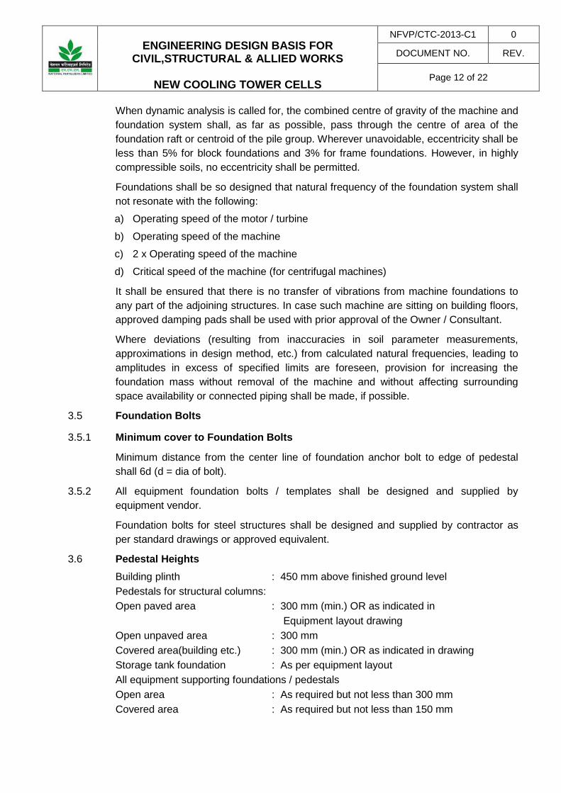
3.3 Machine Foundations
Machine / Mechanical equipment foundations shall satisfy the requirements of IS:2974 and any other parameters as per machine vendors.
Generally, foundations and structures supporting rotating machinery shall be so proportioned that their natural frequency shall not fall within the range of 0.8 to 1.2 of normal operating speed of the equipment. Further for major rotating machinery such as main compressor, the amplitude of foundation of structure during normal operation shall not exceed the allowable amplitude specified by the equipment manufacturer. The above consideration may be omitted for centrifugal pumps and fans and other minor rotating equipment weighing less than 1 ton or if the mass of the rotating parts are less than 1/100th of the mass of foundation installed directly on concrete provided that the weight of foundation is not less than 3 times of the equipment weight. In such cases, dynamic analysis is not necessary.
ENGINEERING DESIGN BASIS FOR
CIVIL,STRUCTURAL & ALLIED WORKS
NEW COOLING TOWER CELLS
NFVP/CTC-2013-C1 0
DOCUMENT NO. REV.
Page 12 of 22
When dynamic analysis is called for, the combined centre of gravity of the machine and foundation system shall, as far as possible, pass through the centre of area of the foundation raft or centroid of the pile group. Wherever unavoidable, eccentricity shall be less than 5% for block foundations and 3% for frame foundations. However, in highly compressible soils, no eccentricity shall be permitted.
Foundations shall be so designed that natural frequency of the foundation system shall not resonate with the following:
a) Operating speed of the motor / turbine
b) Operating speed of the machine
c) 2 x Operating speed of the machine
d) Critical speed of the machine (for centrifugal machines)
It shall be ensured that there is no transfer of vibrations from machine foundations to any part of the adjoining structures. In case such machine are sitting on building floors, approved damping pads shall be used with prior approval of the Owner / Consultant.
Where deviations (resulting from inaccuracies in soil parameter measurements, approximations in design method, etc.) from calculated natural frequencies, leading to amplitudes in excess of specified limits are foreseen, provision for increasing the foundation mass without removal of the machine and without affecting surrounding space availability or connected piping shall be made, if possible.
3.5 Foundation Bolts
3.5.1 Minimum cover to Foundation Bolts
Minimum distance from the center line of foundation anchor bolt to edge of pedestal shall 6d (d = dia of bolt).
3.5.2 All equipment foundation bolts / templates shall be designed and supplied by equipment vendor.
Foundation bolts for steel structures shall be designed and supplied by contractor as per standard drawings or approved equivalent.
3.6 Pedestal Heights Building plinth : 450 mm above finished ground level Pedestals for structural columns: Open paved area : 300 mm (min.) OR as indicated in Equipment layout drawing Open unpaved area : 300 mm Covered area(building etc.) : 300 mm (min.) OR as indicated in drawing Storage tank foundation : As per equipment layout All equipment supporting foundations / pedestals Open area : As required but not less than 300 mm Covered area : As required but not less than 150 mm

ENGINEERING DESIGN BASIS FOR
CIVIL,STRUCTURAL & ALLIED WORKS
NEW COOLING TOWER CELLS
NFVP/CTC-2013-C1 0
DOCUMENT NO. REV.
Page 13 of 22
Stair Pedestals : 300 mm (min.) OR as indicated in equipment Layout drawing. Ladder pedestals : 300 mm
4. DESIGN CRITERIA FOR REINFORCED CONCRETE STRUCTURES
4.1 General 1) All buildings, structures retaining storage structures, trenches, pits etc. shall be of
RCC and designed based on the following IS codes (latest revision with all amendments, issued there to) in general, and other relevant IS codes applicable : IS:456, 875, 1893, 1904, 2911, 2950, 2974, 3370, 4326, 4991, 4998, 5249, 6403, 8009, 13920.
2) Only limit state method as per IS:456 shall be followed for the design unless otherwise specified elsewhere in this document for special structures.
3) All skeletal structures shall be of frame type construction, and detailing shall be as per provision of IS:13920.
4) Where the specified design depth of groundwater table so warrants, all underground pits, tunnels, basements, etc. shall be leak-proof R.C.C. construction using water proofing compounds.
4.2 Concrete Grade
The minimum M25 grade of reinforced cement concrete shall be used for all structures and foundations except for grade slabs / paving for which M20 may be used. For Compressor foundation and for liquid retaining structures (CT Basins and Pump Sumps), M30 grade reinforced concrete shall be used. From durability consideration the minimum cement content and maximum water-cement ratio shall be as follows :
Type of Cement
Plain concrete Reinforced concrete Remarks Exposure Condition Minimum
cement content (kg/m³)
Maximum water-
cement ratio
Minimum cement content (kg/m³)
Maximum water-
cement ratio
43 Grade-OPC 240 0.55 330 0.45 Moderate
75 mm thick lean concrete of grade M10 (nominal mix) shall be provided under all RCC foundations except under base slab of liquid retaining structures where 100 thick concrete of mix M10 (nominal mix) shall be used. The lean concrete shall extend 75 mm beyond the foundation for normal foundations and 100 mm under liquid retaining structures.
Concrete for encasing shall be M20 with 10 mm down aggregate.
Plain cement concrete (PCC) of grade M15 (nominal mix) of minimum 150 mm thickness shall be provided under all masonry wall foundations.

ENGINEERING DESIGN BASIS FOR
CIVIL,STRUCTURAL & ALLIED WORKS
NEW COOLING TOWER CELLS
NFVP/CTC-2013-C1 0
DOCUMENT NO. REV.
Page 14 of 22
Plain cement concrete of grade M20 of minimum 40 mm thickness shall be provided as damp proof course, at plinth level of all masonry walls and to be coated with 3 mm thick bitumen emulsion.
4.3 Reinforcement Bars
High yield strength deformed bars of grade Fe500D conforming to IS:1786 or TMT steel bars shall be used.
4.4 Minimum Cover to Reinforcement
Minimum clear cover shall be provided to all steel reinforcement as per IS:456 & IS:3370.
4.5 Expansion Joints
Concrete structures
Expansion points in concrete structures shall be provided at 30-35 m centers. The expansion joint shall be provided preferably by way of twin columns on a common foundation. Sliding joints shall be avoided as far as possible.
4.6 Deflections
4.6.1 Deflections in concrete structures shall in general be limited by adherence to the limits on span by depth ratio for beams and slabs and length to lateral dimension ratios for columns as prescribed in IS:456. Where special functional / serviceability requirements or large spans demand actual deflections and / or crack widths shall be calculated and the following limits adhered to:
• Total vertical deflection due to all loads including the : Span/250 Effects of temperature creep and shrinkage
• Total horizontal deflection between two floors : Storey height/200 • Crack width (for non-liquid retaining structures) : 0.3 mm
4.7 Miscellaneous Applications
4.7.1 Admixtures
Admixtures shall conform to IS:9103 and to be mixed with concrete (if required) strictly as per manufacturer’s recommendations, after approval of NFL.
Water proofing compound of approved make is to be used in the RCC for all liquid retaining structures as per manufacturers specifications.
Water stops of minimum 230 mm width, of approved make in construction joints is to be provided in construction of liquid retaining structures.
4.7.2 Plinth protection
Each building shall be provided with 1.0 m wide concrete M15, 100 thick laid on 75 mm thick M7.5 concrete with 8 Tor @ 250 c/c both ways Reinforcement bars all round as
ENGINEERING DESIGN BASIS FOR
CIVIL,STRUCTURAL & ALLIED WORKS
NEW COOLING TOWER CELLS
NFVP/CTC-2013-C1 0
DOCUMENT NO. REV.
Page 15 of 22
plinth protection. A surface drain to be provided along-with plinth protection which shall be connected to the drainage system.
4.7.3 Ramps
Ramps for building entrance shall be cast in situ R.C.C. designed as a grade slab and the slope of ramps shall not be less than 1 in 10. Minimum thickness of the slab shall be 150 mm.
4.7.4 Anti Corrosive Paint
All underground concrete structures including top surface of foundations shall be painted with two coats of coal tar epoxy with minimum DFT of 100 microns per coat.
Coal tar epoxy from any of the following paint manufacturers may be used as per their specifications :- Asian Paints, Berger Paints, “Goodlac & Nerolac” and “Janson & Nicolson”.
4.7.5 Masonry Wall
a) All masonry walls from ground floor shall be placed on R.C.C. grade beams. However, light internal partitions may be placed on ground floor slab.
b) All brick masonry (M 7.5 grade) walls shall be considered as 230mm thick, except for partition walls which will be 115 mm thick. However, for fire barrier walls minimum thickness shall be considered as 345 mm.
c) All in-filled brick (M7.5 grade) panels shall be designed to transfer horizontal loads from wind and seismic to the structural frameworks without damage and the extent of brick panel dimensions shall be as per the recommendations in IS. All half masonry wall shall be provided with reinforcement consisting of 2 Nos. of 8 mm diameter bars at every fourth layer.
d) All masonry works shall be designed in accordance with IS:1905, IS:1597, IS:2185, IS:4326 and other relevant IS Codes as applicable. All external brick, stone and hollow concrete block masonry walls shall be of minimum 230, 350 and 250 mm thickness respectively. Masonry shall be plastered with CM 1:6, 12 mm thick on inside surfaces and 20 mm thick on outside surfaces.
5.0 DESIGN CRITERIA FOR STEEL STRUCTURES
5.1 General / Design Methods
5.1.1 Design, fabrication and erection of the above work shall be carried out in accordance with the following IS Codes as applicable to the specific structures, viz, IS:800, 801, 802, 806, 814, 816, 875, 1893, 6533, 9595, etc. Basic consideration of structural frame work shall primarily be stability, ease of fabrication/erection and overall economy, satisfying relevant Indian Standard Codes of Practice. Steel structures adequately braced in vertical and horizontal planes, consistent with functional requirements, shall be preferred over structure having moment connections. Moment connections, if adopted, shall be fully rigid as per IS:800. Where fully rigid joints are adopted they shall

ENGINEERING DESIGN BASIS FOR
CIVIL,STRUCTURAL & ALLIED WORKS
NEW COOLING TOWER CELLS
NFVP/CTC-2013-C1 0
DOCUMENT NO. REV.
Page 16 of 22
generally be confined to the major axis of the column member. Flare stack supporting structure shall be adequately braced on all four faces.
Structural elements, continuously exposed to temperatures above 200º C, shall be designed for reduced stress as per Table-4 of IS:6533 (Part-2). The expected temperature of steel components shall not be allowed to exceed 400 º C. The structures connected to column, heater vessels working at high temperatures shall not be rigidly connected with staircase and adjoining structures, which are on ambient temperatures.
5.1.2 Crane gantry girders shall generally be of welded construction and of single span length. Chequered plate shall be used for gantry girder walkway flooring.
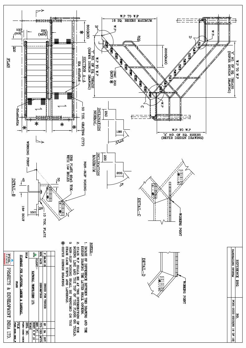
5.1.3 Steel staircases shall have channels provided as stringers with minimum clear width of 1000 mm. The vertical height between successive landings shall not exceed 4.0 meters. Treads shall be minimum 250 m wide made of grating (with curved chequered plate nosing) spaced equally so as to restrict the rise to maximum 150 mm. If relevant local by-laws or applicable Factory Act Rules stipulates more stringent requirements in this regard, the same shall be adhered to.
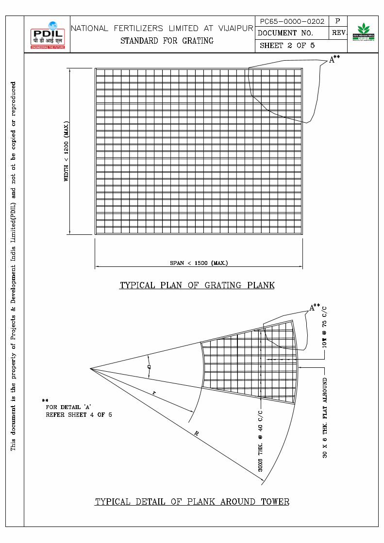
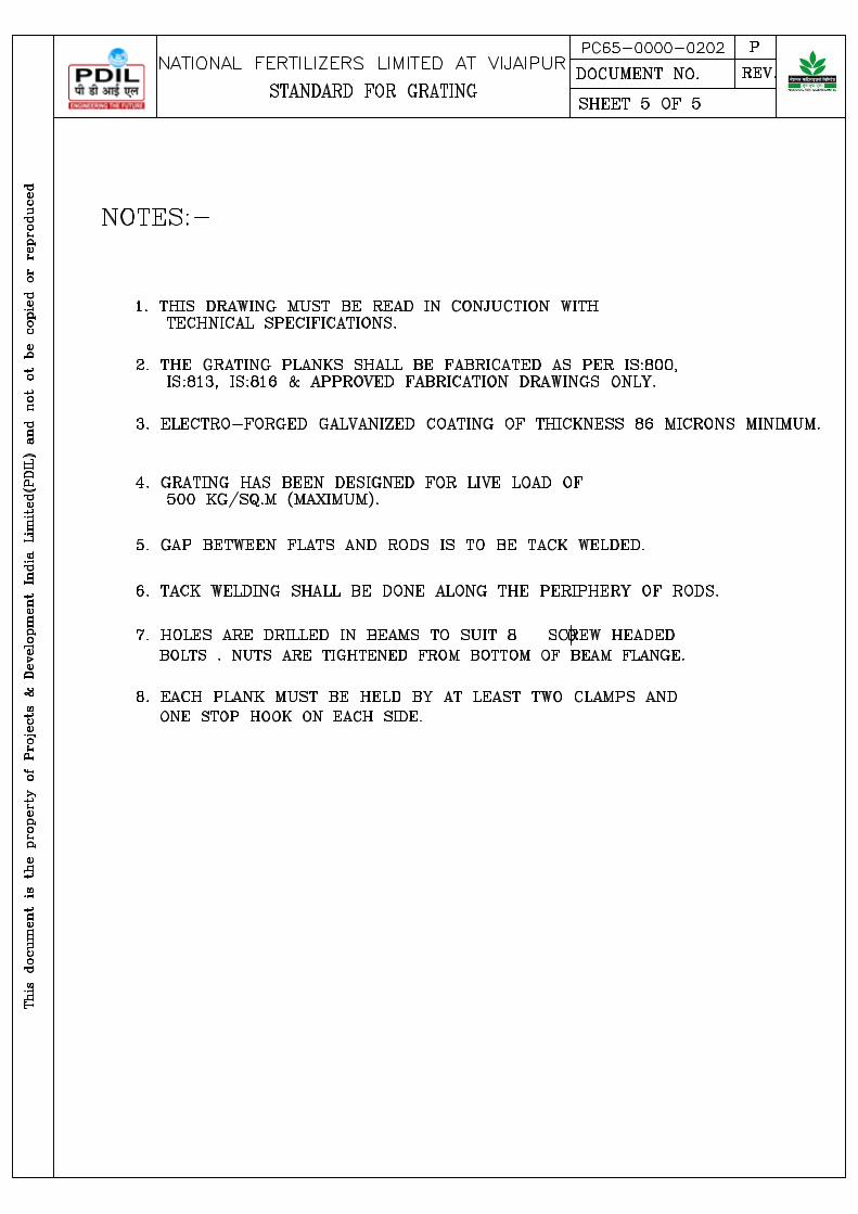
5.1.4 Electro-forged galvanized MS gratings shall be minimum 30 mm deep. The maximum size of voids in the grating shall be limited to 34 mm x 65 mm. The minimum thickness of galvanizing shall be 86 microns. Gratings shall be suitable for the operation and maintenance loads for the floors.
5.1.5 Bolted connections shall be adopted as far as practicable, except for cases where welded connections are required viz. (Galvanized) electrical switchyard structures and transmission towers. Structural connections shall have minimum two bolts of 16 mm dia. unless otherwise limited by the size of members
5.1.6 Lock nuts shall be provided for anchor bolts of tall structures, tall process columns, vibrating equipment, etc.
5.1.7 Minimum two nuts shall used for all anchor bolts except for ladder, stair and hand rail.
5.2 Expansion Joints
Expansion joints shall be provided at 80 – 100 m centres, where possible, column bracing shall be provided at the center of a longitudinal frame, rather than at the ends so as to avoid constraints on free expansion.
5.3 Steel Grade
Structural steel shall be of yield stress of 250 Mpa conforming to grade B of IS:2062. Tubular steel shall conform to Yst 310 of IS:1161 & 4 IS: 4923.
5.4 Limiting Permissible Stresses Permissible stresses in structural members shall be as specified in various codes. IS:800 - Hot rolled sections (excluding transmission towers and Switchyard structures).

ENGINEERING DESIGN BASIS FOR
CIVIL,STRUCTURAL & ALLIED WORKS
NEW COOLING TOWER CELLS
NFVP/CTC-2013-C1 0
DOCUMENT NO. REV.
Page 17 of 22
IS:801 - Cold formed light gauge sections IS:802 - Transmission towers & switchyard structures IS:806 - Tubular Structures Permissible stresses in bolts shall be as specified in: IS:800 - Hot rolled sections IS:801 - Cold formed light gauge sections IS:802 - Transmission towers & switchyard structures IS:806 - Tubular Structures
Permissible stresses in welds shall be as specified in: IS:801 - Cold formed light gauge sections IS:806 - Metal Arc Welding
5.5 Limiting Deflection
a) The limiting permissible vertical deflection for structural steel members shall be as
specified below :-
− Gantry girder for electric overhead crane (Capacity up to 50T)
: L/750
− Gantry girder for electric overhead crane (Capacity over 50T)
: L/1000
− Gantry girder for manually operated crane : L/500
− Girder beam for supporting dynamic equipment/hoist : L/450
− Grating / Chequered plate : L/200 or 6mm Whichever is less
− Purlins supporting any type of roofing material : L/200
− Under (dead load + live load) or (dead load + wind Load ) conditions
:
− Other structural components : As specified in relevant IS, Where “L” represents the span
− The limiting permissible horizontal deflection for multistoried steel structure/ building including flare stack
: Height/325
5.6 Minimum Thickness
5.6.1 Structural Components
ENGINEERING DESIGN BASIS FOR
CIVIL,STRUCTURAL & ALLIED WORKS
NEW COOLING TOWER CELLS
NFVP/CTC-2013-C1 0
DOCUMENT NO. REV.
Page 18 of 22
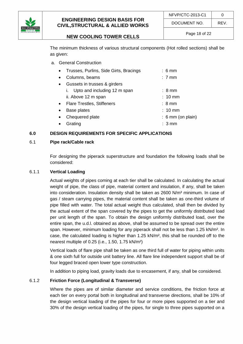
The minimum thickness of various structural components (Hot rolled sections) shall be as given:
a. General Construction
• Trusses, Purlins, Side Girts, Bracings : 6 mm • Columns, beams : 7 mm • Gussets in trusses & girders
i. Upto and including 12 m span : 8 mm ii. Above 12 m span : 10 mm
• Flare Trestles, Stiffeners : 8 mm • Base plates : 10 mm • Chequered plate : 6 mm (on plain) • Grating : 3 mm
6.0 DESIGN REQUIREMENTS FOR SPECIFIC APPLICATIONS
6.1 Pipe rack/Cable rack
For designing the piperack superstructure and foundation the following loads shall be considered:
6.1.1 Vertical Loading
Actual weights of pipes coming at each tier shall be calculated. In calculating the actual weight of pipe, the class of pipe, material content and insulation, if any, shall be taken into consideration. Insulation density shall be taken as 2600 N/m³ minimum. In case of gas / steam carrying pipes, the material content shall be taken as one-third volume of pipe filled with water. The total actual weight thus calculated, shall then be divided by the actual extent of the span covered by the pipes to get the uniformly distributed load per unit length of the span. To obtain the design uniformly distributed load, over the entire span, the u.d.l. obtained as above, shall be assumed to be spread over the entire span. However, minimum loading for any piperack shall not be less than 1.25 kN/m². In case, the calculated loading is higher than 1.25 kN/m², this shall be rounded off to the nearest multiple of 0.25 (i.e., 1.50, 1.75 kN/m²)
Vertical loads of flare pipe shall be taken as one third full of water for piping within units & one sixth full for outside unit battery line. All flare line independent support shall be of four legged braced open lower type construction.
In addition to piping load, gravity loads due to encasement, if any, shall be considered.
6.1.2 Friction Force (Longitudinal & Transverse)
Where the pipes are of similar diameter and service conditions, the friction force at each tier on every portal both in longitudinal and transverse directions, shall be 10% of the design vertical loading of the pipes for four or more pipes supported on a tier and 30% of the design vertical loading of the pipes, for single to three pipes supported on a

ENGINEERING DESIGN BASIS FOR
CIVIL,STRUCTURAL & ALLIED WORKS
NEW COOLING TOWER CELLS
NFVP/CTC-2013-C1 0
DOCUMENT NO. REV.
Page 19 of 22
tier. Longitudinal friction force shall be considered as uniformly distributed over the entire span of the beam at each tier and transverse friction force shall be considered as a concentrated load at each tier level. Friction forces on T-supports and trestles shall be taken as 30% of the vertical loading. Both longitudinal and transverse friction forces shall be considered to be acting simultaneously.
For two-phase fluid flow/transfer lines frictional force shall be minimum 50% of the weight of pipe including contents & insulation, acting simultaneously in transverse & longitudinal direction.
6.1.3 Anchor and Guide Force (Thermal Load)
Anchor and guide force (thermal load) in transverse and longitudinal direction shall be as per piping data.
6.1.4 Loading on intermediate Beam at Tier Level
Intermediate beam at tier level shall be designed for 25% of load on main portal beams in transverse direction. A reduction of 10% in vertical loading shall be considered for main portal beams, if intermediate beams are provided.
6.1.5 Loading on Longitudinal beams
Longitudinal beams connecting portal columns shall be sufficiently strong to sustain 25% of the load on the transverse beams. The total load shall be assumed as two equal concentrated loads acting at 1/3rd span. Other longitudinal axial forces coming on it from the design of the supporting system shall also be simultaneously taken into account in the design of the longitudinal beam. Friction & anchor forces, if specifically given by the Piping Specialist, shall also be catered for in the design. Loads from monorails, when supported from these beams, shall also be considered to be acting simultaneously along with all other loads mentioned above.
6.1.6 Cable Tray and Walkway Loads
The estimated actual load from electrical, instrumentation trays shall be considered at the specified locations, together with walkways, platforms for valve operation, wherever provided.
6.1.7 Wind Force
Transverse wind loading shall be calculated depending on the width of the piperack as per the following table. This force shall be considered irrespective of the height between two tiers.
Width of Piperack Wind Force at each Tier level(N)
− Upto 4 m 1.25 x p x s
− Above 4 m but upto 6 m 1.50 x p x s
ENGINEERING DESIGN BASIS FOR
CIVIL,STRUCTURAL & ALLIED WORKS
NEW COOLING TOWER CELLS
NFVP/CTC-2013-C1 0
DOCUMENT NO. REV.
Page 20 of 22
− Above 6 m but upto 10 m 2.00 x p x s
− Above 10 m projected height x p x s
Where p = Horizontal wind pressure as per IS:875 (N/m²)
s = Spacing of portals (m)
For pipe racks of width greater than 10 m, the projected height shall be lesser of the following two:
1. 0.8 X (diameter of largest pipe including insulation (m) + tan 10º × (width of rack (m).
2. Height between consecutive tiers
6.1.8 For flare header or any other line supported on extended leg of piperack, the wind force shall be considered separately.
6.1.9 Seismic Loads
Seismic loads shall be as per IS:1893(Latest Revision) .
6.1.10 Pipe racks should be adequately braced in all possible directions, consistent with function requirements.
6.1.11 Limiting permissible horizontal deflection for piperack shall be height / 325.
7.0 DESIGN CRITERIA –GENERAL 7.1 Site Grading 7.1.1 The grading of the area shall be done by cutting and filling with the following:
1. Cutting Area : Thoroughly rolled and compacted. 2. Filling Area : Compacted in layers not exceeding 20cm to achieve minimum
95% of maximum dry density.
7.1.2 Site grading philosophy shall be based on following:
Finished Ground Levels (FGL) and Highest Point of Paving (HPP) shall be finalised by CONTRACTOR, in consultation with OWNER / PMC, based on contour survey of the Unit, levels of adjacent units and levels of adjacent Roads.
7.1.3 Slope in Graded Areas (Between various grades) 1. General Site Grading : 1 in 500 to 1 in 1000 2. Micro grading, after completion of major : 1 in 200 construction (for road corridors)
7.2 Roads 7.2.1 All roads surface shall be prepared in accordance with Section-16 of CPWD
Specifications & designed in accordance with IRC 37 (Latest revision) for crossing of drains, pipes, cable trenches etc; suitable culverts shall be provided. The culverts shall be designed for class `AA' loading and also checked for class `A' loading in accordance with IRC.
ENGINEERING DESIGN BASIS FOR
CIVIL,STRUCTURAL & ALLIED WORKS
NEW COOLING TOWER CELLS
NFVP/CTC-2013-C1 0
DOCUMENT NO. REV.
Page 21 of 22
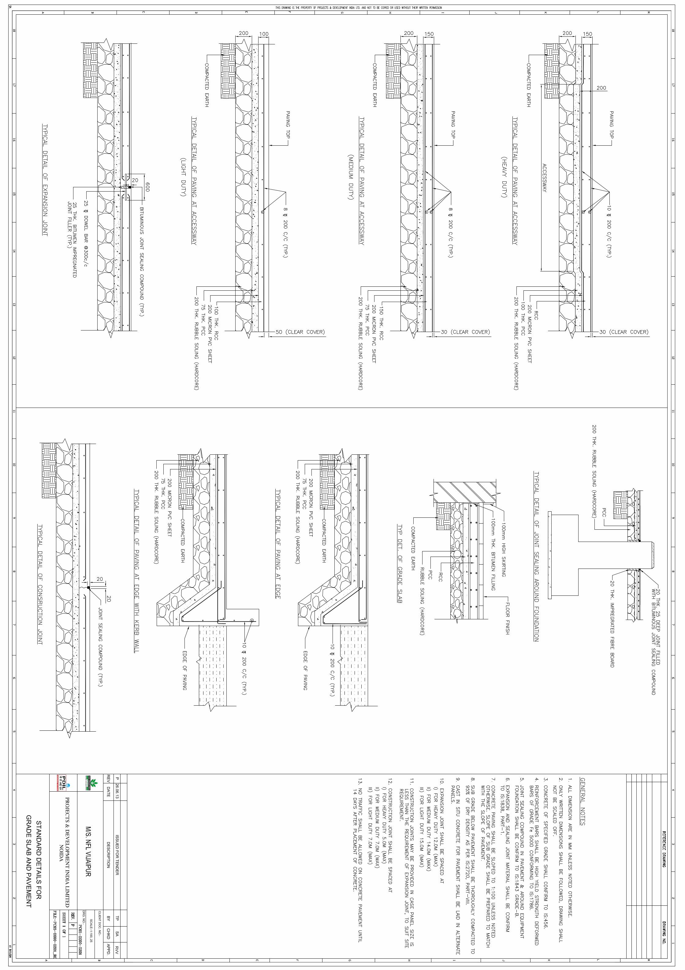
7.3 Concrete Paving 7.3.1 General
RCC paving shall be laid in cast-in-situ panels of 3.0 meter X 3.0 meter size with expansion joints, each panel being cast in a single pour.
Hard stands should be designed and provided by contractor, based on required crane capacity. Here called for by Owner, the same shall be demolished after erection, and surface made good.
Provision of trenches, drains, sealing of trench covers, inserts, thickening for pipe /equipment supports etc. shall be made while construction pavements, as detailed in drawings.
Acid / alkali / chemical resistant coating as required shall be applied in areas where such corrosive materials are likely to come in contact with concrete.
Suitable drainage arrangements will be provided within curbed areas around pumps, for drainage leaks. Similarly, suitable drainage arrangement shall be provided at streaming points also.
Finish of 50 thick concrete screed, with non metallic (Quartz based) hardener topping shall be provided on paving after erection and commissioning of equipment is over.
7.3.2 Joints Expansion joints & Contraction joints shall be as per standard drawings enclosed in Tender.
7.3.3 Slope : 1 in 100 (minimum) 7.3.4 Minimum requirements of paving in various areas (As given in the standard drawing)
1. Paving within Process & Utility areas for maintenance compatible to crane movements / dropout / Loading / Unloading areas /Vehicular movement areas
: Heavy duty (200 mm thk. RCC with double layer reinforcement of 10 tor @200 C/c)
2. Non vehicular movement areas
a. Unit : Medium Duty (150 mm thick RCC)
b. Utilities : Medium Duty (150 mm thick RCC)
3. Pipe rack : Light Duty (100 mm thick RCC)
Paving and trenches including covers in process units shall be suitable for Hydra crane movement. Where movement of bigger cranes for maintenance is envisaged, paving and trenches including covers shall be designed for the loads arising from the same.
7.4 Storm Water Drainage 7.4.1 Storm water drains shall be sized for the higher discharge arising out of either rain
water or fire fighting water.
Minimum width of drains: 500 mm (depth > 500mm)
Run off coefficient ‘K’
ENGINEERING DESIGN BASIS FOR
CIVIL,STRUCTURAL & ALLIED WORKS
NEW COOLING TOWER CELLS
NFVP/CTC-2013-C1 0
DOCUMENT NO. REV.
Page 22 of 22
1. Paved Area Run off coefficient ‘K’
− concrete : 1.0
− bituminous : 0.9
2. Unpaved Areas : 0.7
3. Unusable Areas Like Green Belt : 0.4
7.4.4 Disposal of Storm Water Storm water drains shall not be combined with oily waste sewer / contaminated effluent rain water system, etc.
First flush of run-off water shall be recovered in the Chemical effluent sumps. Volume shall correspond to the first 15 minutes of Max. rain fall flow. Last incoming water shall overflow to the outfall of storm water network. Clean rain water shall be drained by appropriate (RCC) Channel up to the Battery limit of plant.
TECHNICAL SPECIFICATIONS OF NIT FOR NFVP/CTC/2013-C2 0 PROJECT :ADDITAIONAL COOLING TOWER CELLS DOCUMENT NO REV
CLIENT : NFL VIJAIPUR Page 1 of 20
FORM NO: 02-0000-0021F3 REV3 All rights reserved
ANNEXURE C-2
TECHNICAL SPECIFICATIONS
FOR
CIVIL, STRUCTURAL
AND
OTHER ALLIED WORKS
TECHNICAL SPECIFICATIONS OF NIT FOR NFVP/CTC/2013-C2 0
PROJECT :ADDITAIONAL COOLING TOWER CELLS DOCUMENT NO REV
CLIENT : NFL VIJAIPUR Page 2 of 20
CONTENTS
SL. NO.
DESCRIPTION PAGE NO.
1. GENERAL 3 2. REFERENCE CODES AND
STANDARDS 3
3. EARTH WORK 4 4. PLAIN AND REINFORCED CONCRETE
WORK 8
5. STEEL REINFORCEMENT 10 6. FORM WORK 10 7. BRICK WORK 11 8. STRUCTURAL STEEL WORK 12 9. PAINTING ON STRUCTURAL STEEL 15
10. STEEL/ALUMINIUM DOORS,WINDOWS AND VENTILATORS
17
11. FLOORING AND PAVING 17 12. PLASTERING 18 13. EXTERIOR PAINTING 19 14. GLAZING 19 15 STORM WATER DRAIN 19 16 REFERENCE DRAWINGS 19
TECHNICAL SPECIFICATIONS OF NIT FOR NFVP/CTC/2013-C2 0
PROJECT :ADDITAIONAL COOLING TOWER CELLS DOCUMENT NO REV
CLIENT : NFL VIJAIPUR Page 3 of 20
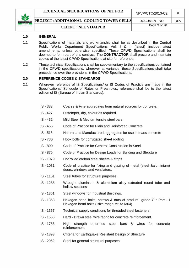
1.0 GENERAL 1.1 Specifications of materials and workmanship shall be as described in the Central
Public Works Department Specifications Vol. I & II (latest) include latest amendments, unless otherwise specified. These CPWD Specifications shall be deemed to form part of this contract. The CONTRACTOR shall procure and maintain copies of the latest CPWD Specifications at site for reference.
1.2 These technical Specifications shall be supplementary to the specifications contained in the CPWD specifications, wherever at variance, these Specifications shall take precedence over the provisions in the CPWD Specifications.
2.0 REFERENCE CODES & STANDARDS 2.1 Wherever reference of IS Specifications/ or IS Codes of Practice are made in the
Specifications/ Schedule of Rates or Preambles, reference shall be to the latest edition of IS (Bureau of Indian Standards).
IS - 383 Coarse & Fine aggregates from natural sources for concrete.
IS - 427 Distemper, dry, colour as required.
IS - 432 Mild Steel & Medium tensile steel bars.
IS - 456 Code of Practice for Plain and Reinforced Concrete.
IS - 515 Natural and Manufactured aggregates for use in mass concrete
IS - 730 Hook bolts for corrugated sheet roofing
IS - 800 Code of Practice for General Construction in Steel
IS - 875 Code of Practice for Design Loads for Building and Structure
IS - 1079 Hot rolled carbon steel sheets & strips
IS - 1081 Code of practice for fixing and glazing of metal (steel &aluminium) doors, windows and ventilators.
IS - 1161 Steel tubes for structural purposes.
IS - 1285 Wrought aluminium & aluminium alloy extruded round tube and hollow sections
IS - 1361 Steel windows for Industrial Buildings.
IS - 1363 Hexagon head bolts, screws & nuts of product grade C : Part - I Hexagon head bolts ( size range M5 to M64)
IS - 1367 Technical supply conditions for threaded steel fasteners
IS - 1566 Hard - Drawn steel wire fabric for concrete reinforcement.
IS - 1786 High strength deformed steel bars & wires for concrete reinforcement.
IS - 1893 Criteria for Earthquake Resistant Design of Structure
IS - 2062 Steel for general structural purposes.

TECHNICAL SPECIFICATIONS OF NIT FOR NFVP/CTC/2013-C2 0
PROJECT :ADDITAIONAL COOLING TOWER CELLS DOCUMENT NO REV
CLIENT : NFL VIJAIPUR Page 4 of 20
IS - 2116 Sand for masonry mortars.
IS - 2212 Code of practice for brickwork.
IS - 2386 Methods of test for aggregates.
IS - 2835 Flat transparent sheet glass
IS - 4021 Timber door, window and ventilator frames
IS - 4923 Hollow Steel sections for structural use.
IS - 4925 Concrete batching and mixing plant.
IS - 5410 Cement Paint
IS - 6477 Dimensions for wrought aluminium&aluminium alloys, extruded hollow sections.
IS - 7318 Fusion welding of steel.
IS - 10262 Recommended guidelines for concrete mix design.
IS - 13920 Ductile Detailing of Reinforced Concrete Structures.
IS - 14871 Products in Fibre Reinforced Cement – Long Corrugated or Asymmetrical Section Sheets and Fittings for Roofing and Cladding - Specification
3.0 EARTHWORK 3.1 Excavation 3.1.1 Excavation shall be carried out in soil of any nature and consistency, in the presence
of water or in the dry, met on the site to the lines, levels and contours shown on the detailed drawings and CONTRACTOR shall remove all excavated materials to soil heaps on site or transport for use in filling on the site or stack them for reuse as directed by the Engineer-in-Charge.
3.1.2 Surface dressing shall be carried out on the entire area occupied by the buildings including plinth protection as directed without any extra cost. The depths of excavation shown on the drawings are the depths after surface dressing.
3.1.3 The site around all buildings and structures to a width of 3 metres beyond the edge of plinth protection, ramps, steps, etc. shall be dressed and sloped away from the buildings.
3.1.4 Black cotton soil, and other expansive or unsuitable soils excavated shall not be used for filling in foundations, and plinths of buildings or in other structures including manholes, septic tanks etc. and shall be disposed off within the contract area marked on the drawings, as directed, levelled and neatly dressed.
3.1.5 In case of trenches exceeding 2 metres depth or where soil is soft or slushy, the sides of trenches shall be protected by timbering and shoring. The CONTRACTOR shall be responsible to take all necessary steps to prevent the sides of trenches from caving in or collapsing. The extent and type of timbering and shoring shall be as directed by the Engineer-in-Charge.

TECHNICAL SPECIFICATIONS OF NIT FOR NFVP/CTC/2013-C2 0
PROJECT :ADDITAIONAL COOLING TOWER CELLS DOCUMENT NO REV
CLIENT : NFL VIJAIPUR Page 5 of 20
3.1.6 Where the excavation is to be carried out belowthe foundation level of adjacent
structure, the precautions to be taken such as under pinning, shoring and strutting etc. shall be determined by Engineer-in-Charge. No excavation shall be done unless such precautionary measures are carried out as per directions of Engineer-in-Charge.
3.1.7 Specification for Earth work shall also apply to excavation in rock in general. The excavation in rock shall be done such that extra excavation beyond the required width and depth as shown in drawings is not made. If the excavation done in depth greater than required /ordered. The CONTRACTOR shall fill the extra excavation with concrete of mix 1:5:10 as the foundation concrete at his own cost.
3.1.8 CONTRACTOR shall make all necessary arrangements for dewatering / defiling as required to carry out proper excavation work by bailing or pumping out water, which may accumulate in the excavation pit from any cause/ source whatsoever.
3.1.9 CONTRACTOR shall provide suitable draining arrangements at his own cost to prevent surface water entering the foundation pits from any source.
3.1.10 The CONTRACTOR is forbidden to commence the construction of structures or to carry out concreting before Engineer-in-Charge has inspected, accepted and permitted the excavation bottom.
3.1.11 Excavation in disintegrated rock means rock or Bouldersincluding brickbats which may be quarried or split with crow bars. This will also include laterite and hard conglomerate.
3.1.12 Excavations in hard rock - meant excavation made in hard rock to be done manually, or by blasting using only explosives and / or pneumatic hammers. In case of blasting, control blasting should be adopted depending on site conditions. For using explosives CONTRACTOR shall follow all provisions of Indian Explosives Act / Rules 1983, corrected / revised up to date.
3.1.13 In case of hard rock excavation to be carried out using explosives the, CONTRACTOR shall obtain the written approval in advance. Blasting using explosives shall not be permitted if the work is to be executed in the plant area. Contractor has to use other techniques in such case.
3.1.14 The measurements for excavations shall be restricted and limited to minimum excavation line as per drawing for payment purposes.
3.1.15 Adequate protective measures shall be taken to see that the excavation does not affect or damage adjoining structures. The CONTRACTOR shall take all measures required for ensuring stability of the excavation and safety of property and people in the vicinity. The CONTRACTOR shall erect and maintain during progress of work, temporary fences around dangerous excavations at no extra cost.
3.1.16 Excavation in ordinary soil means excavation in ordinary hard soil including stiff heavy clay, hard shale, or compact moorum, or any materials, which can be removed by the ordinary application of spades, shovels, picks and pick axes. This shall also include removal of isolated boulders each having a volume not more than 0.50m³.
3.1.17 Excavation in soft rock includes limestone, sandstone, laterite, hard conglomerates, etc. or other rock which can be quarried or split with crowbars or wedges. This shall also include excavation of tarred pavements, masonry work and rock boulders each

TECHNICAL SPECIFICATIONS OF NIT FOR NFVP/CTC/2013-C2 0
PROJECT :ADDITAIONAL COOLING TOWER CELLS DOCUMENT NO REV
CLIENT : NFL VIJAIPUR Page 6 of 20
having a volume of not more than 0.25m³.
3.1.18 Excavation in hard rock includes any rock bound in ledges or masses in its original form or cement concrete for which in the opinion of the Engineer-in-Charge, requires the use of compressed air, equipment, sledge hammer and blasting or non-explosive materials viz. Acconex manufactured by A.C.C. Ltd. Specifications and instructions for use shall be as per manufacturer.
3.1.19 In case of any difficulty concerning the interpretation of type of soil as mentioned above, the Engineer-in-Charge shall decide whether the excavation in a particular material is in ordinary soil, soft rock or hard rock and his decision in this matter shall be final and binding on the CONTRACTOR and without appeal.
3.2 Filling 3.2.1 Back filling of excavations in trenches, foundations and elsewhere shall consist of
one of the following materials approved by Engineer-in-Charge. 1) Soil 2) Sand 3) Moorum 4) Hard-core 5) Stone/gravel
All back filling material shall be approved by the Engineer-in-Charge. 3.2.2 Soil filling - Soil material shall be free from rubbish, roots, hard lumps and any other
foreign organic material. Filling shall be done in regular horizontal layers each not exceeding 20 cm. depth.
3.2.3 Back filling around completed foundations, structures, trenches and in plinth shall be done to the lines and levels shown on the drawings.
3.2.4 Back filling around pipes in the trench shallbe done after hydro testing is done.
3.2.5 Back filling around liquid retaining structuresshall be done only after leakage testing is completed and approval of Engineer-in-Charge is obtained.
3.2.6 Sand used for filling under foundation concrete, around foundation and in plinth etc. shall be fine/ coarse, strong, clean, free from dust, organic and deleterious matter. The sand filling under foundation shall be rammed with Mech. compactor. Sand material shall be approved by Engineer-in-Charge.
3.2.7 Moorum for filling, where ordered, shall be obtainedfrom approved pits and quarries which contain siliceous material and natural mixture of clay. Moorum shall not contain any admixture of ordinary earth. Size of moorum shall vary from dust to 10 mm.
3.2.8 Hard-core shall be of broken stone of 90 mm to 10 mm size suitable for providing a dense and compact sub grade. Stones shall be sound, free from flakes, dust and other impurities. Hard core filling shall be spread and levelled in layers, 15 cm thick, watered and well compacted with ramming or with mechanical / hand compacts including hand packing wherever required.
TECHNICAL SPECIFICATIONS OF NIT FOR NFVP/CTC/2013-C2 0
PROJECT :ADDITAIONAL COOLING TOWER CELLS DOCUMENT NO REV
CLIENT : NFL VIJAIPUR Page 7 of 20
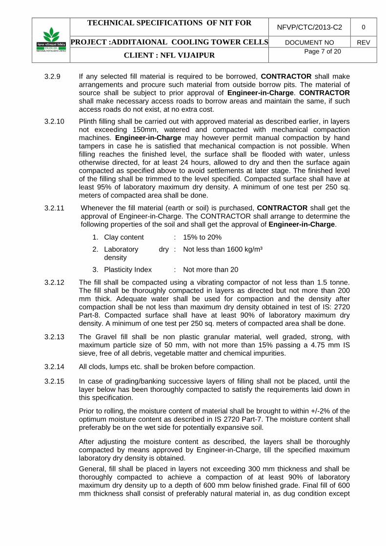
3.2.9 If any selected fill material is required to be borrowed, CONTRACTOR shall make
arrangements and procure such material from outside borrow pits. The material of source shall be subject to prior approval of Engineer-in-Charge. CONTRACTOR shall make necessary access roads to borrow areas and maintain the same, if such access roads do not exist, at no extra cost.
3.2.10 Plinth filling shall be carried out with approved material as described earlier, in layers not exceeding 150mm, watered and compacted with mechanical compaction machines. Engineer-in-Charge may however permit manual compaction by hand tampers in case he is satisfied that mechanical compaction is not possible. When filling reaches the finished level, the surface shall be flooded with water, unless otherwise directed, for at least 24 hours, allowed to dry and then the surface again compacted as specified above to avoid settlements at later stage. The finished level of the filling shall be trimmed to the level specified. Compacted surface shall have at least 95% of laboratory maximum dry density. A minimum of one test per 250 sq. meters of compacted area shall be done.
3.2.11 Whenever the fill material (earth or soil) is purchased, CONTRACTOR shall get the approval of Engineer-in-Charge. The CONTRACTOR shall arrange to determine the following properties of the soil and shall get the approval of Engineer-in-Charge.
1. Clay content : 15% to 20%
2. Laboratory dry density
: Not less than 1600 kg/m³
3. Plasticity Index : Not more than 20
3.2.12 The fill shall be compacted using a vibrating compactor of not less than 1.5 tonne. The fill shall be thoroughly compacted in layers as directed but not more than 200 mm thick. Adequate water shall be used for compaction and the density after compaction shall be not less than maximum dry density obtained in test of IS: 2720 Part-8. Compacted surface shall have at least 90% of laboratory maximum dry density. A minimum of one test per 250 sq. meters of compacted area shall be done.
3.2.13 The Gravel fill shall be non plastic granular material, well graded, strong, with maximum particle size of 50 mm, with not more than 15% passing a 4.75 mm IS sieve, free of all debris, vegetable matter and chemical impurities.
3.2.14 All clods, lumps etc. shall be broken before compaction.
3.2.15 In case of grading/banking successive layers of filling shall not be placed, until the layer below has been thoroughly compacted to satisfy the requirements laid down in this specification.
Prior to rolling, the moisture content of material shall be brought to within +/-2% of the optimum moisture content as described in IS 2720 Part-7. The moisture content shall preferably be on the wet side for potentially expansive soil.
After adjusting the moisture content as described, the layers shall be thoroughly compacted by means approved by Engineer-in-Charge, till the specified maximum laboratory dry density is obtained.
General, fill shall be placed in layers not exceeding 300 mm thickness and shall be thoroughly compacted to achieve a compaction of at least 90% of laboratory maximum dry density up to a depth of 600 mm below finished grade. Final fill of 600 mm thickness shall consist of preferably natural material in, as dug condition except

TECHNICAL SPECIFICATIONS OF NIT FOR NFVP/CTC/2013-C2 0
PROJECT :ADDITAIONAL COOLING TOWER CELLS DOCUMENT NO REV
CLIENT : NFL VIJAIPUR Page 8 of 20
that stones larger than 100 mm shall be removed. It shall be placed in layers not exceeding 150 mm thickness and compacted to achieve of at least 95% of laboratory maximum dry density. Each layer shall be tested in field for density and accepted by Engineer-in-Charge, subject to achieving the required density before laying the next layer. A minimum of one test per 250sq meters for each layer shall be conducted.
If the layer fails to meet the required density, it shall be reworked or the material shall be replaced and method of construction altered as directed by Engineer-in-Charge to obtain the required density.
The filling shall be finished in conformity with the alignment, levels, cross-section and dimensions as shown in the drawing.
Extra material shall be removed and disposed off as directed by the Engineer-in-Charge.
4.0 PLAIN AND REINFORCED CONCRETE WORK This specifications deals with cement concrete, plain or reinforced, for general use, and covers the requirements for concrete materials, their storage, grading, mix design, strength & quality requirements, pouring at all levels, reinforcements, protection, curing, form work, finishing, painting, admixtures, inserts and other miscellaneous works.
4.1 Materials 4.1.1 Cement: Any of the following cements may be used as required.
IS - 8112 43 Grade ordinary Portland cement
IS - 12269 53 Grade ordinary port land cement
4.1.2 Water: Water used for mixing and curing concrete and mortar shall conform to the requirements as laid down in IS: 456. Sea water shall not be used for concrete work.
4.1.3 Aggregates: Coarse and fine aggregates for cement concrete plain and reinforced shall conform to the requirements of IS 383 and / or IS 515. Before using, the aggregates shall be tested as per IS: 2386.
Coarse aggregate: Coarse aggregate for all cement concrete work shall be broken or crushed hard stone, black trap stone obtained from approved Quarries or gravel.
Sand: Fine aggregate for concrete work shall be coarse sand from approved sources. Grading of coarse sand shall be within grading zones I, II or III laid down in IS: 383, table 4. If required the aggregates (both fine and coarse) shall have to be thoroughly washed and graded as per direction of Engineer-in-Charge.
4.2 Mixing All cement concrete plain or reinforced shall be machine mixed. Mixing by hand may be employed where quantity of concrete involved is small, with the specific prior permission of the Engineer-in-Charge. 10% extra cement shall be added in case of hand mixing as stipulated in IS-456.
For large and medium project sites the concrete shall be sourced from ready- mixed concrete plants or from on site or off site batching and mixing plants (IS 4926)

TECHNICAL SPECIFICATIONS OF NIT FOR NFVP/CTC/2013-C2 0
PROJECT :ADDITAIONAL COOLING TOWER CELLS DOCUMENT NO REV
CLIENT : NFL VIJAIPUR Page 9 of 20
4.3 Water Cement Ratio, Laying & Curing Water Cement Ratio, Laying & Curing shall be done as per IS:456.
4.6 Grades of Concrete 4.6.1 Grades lower than M 25 shall not be used in reinforced concrete, except for
pavement and grade slabs where concrete of grade M 20 may be used.
4.6.2 A sieve analysis test of aggregates shall be carried out as and when the source of supply is changed without extra charge notwithstanding the mandatory test required to be carried out as per CPWD specification.
4.6.5 All tests in support of mix design shall be maintained as a part of records of the contract. Test cubes for mix design shall be prepared by the CONTRACTOR under his own arrangements and at his costs, but under the supervision of the Engineer-in-Charge.
4.7 Design Mix Concrete 4.7.1 Design mix shall be allowed for major works where it is contemplated to be used by
installing weigh batch mixing plant as per IS 4925. At the time of tendering, the CONTRACTOR, after taking into account the type of aggregates, plant and method of laying he intends to use, shall allow in his tender for the design mix i.e., aggregate/cement and water/cement ratios which he considers will achieve the strength requirements specified, and workability for concrete to be properly finished.
4.8.2 Before commencement of concreting, CONTRACTOR shall carry out preliminary tests for design mix on trial mixes proposed by him in design of mix to satisfy the Engineer-in-Charge that the characteristic strength is obtained. In this regard, CONTRACTOR may consult govt. approved/reputed institute to get design mix done as per IS 10262 at his own cost. The concrete mix to be actually used shall be approved by the Engineer-in-Charge.
4.8.3 Notwithstanding the above, the following shall be the maximum combined weight of coarse and fine aggregate per 50 kg of cement.
Grade of Concrete Maximum weight of fine & coarse aggregates together per 50 kg of cement
(for nominal mix only)
1. M - 10 480 kg
2. M - 15 330 kg
3. M - 20 250 kg
4.8.4 The workability of concrete produced shall be adequate, so that the concrete can be properly placed and compacted. The slump shall be as per IS 456.
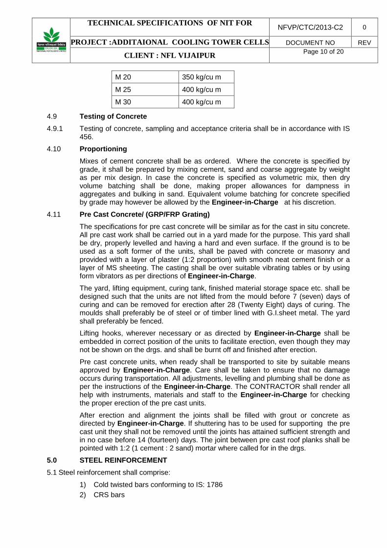
4.8.5 The minimum consumption of the cement irrespective of design mix shall not be less than the following:
M 7.5 170 kg/cu m
M 10 220 kg/cu m
M 15 300 kg/cu m
TECHNICAL SPECIFICATIONS OF NIT FOR NFVP/CTC/2013-C2 0
PROJECT :ADDITAIONAL COOLING TOWER CELLS DOCUMENT NO REV
CLIENT : NFL VIJAIPUR Page 10 of 20
M 20 350 kg/cu m
M 25 400 kg/cu m
M 30 400 kg/cu m
4.9 Testing of Concrete 4.9.1 Testing of concrete, sampling and acceptance criteria shall be in accordance with IS
456.
4.10 Proportioning Mixes of cement concrete shall be as ordered. Where the concrete is specified by grade, it shall be prepared by mixing cement, sand and coarse aggregate by weight as per mix design. In case the concrete is specified as volumetric mix, then dry volume batching shall be done, making proper allowances for dampness in aggregates and bulking in sand. Equivalent volume batching for concrete specified by grade may however be allowed by the Engineer-in-Charge at his discretion.
4.11 Pre Cast Concrete/ (GRP/FRP Grating) The specifications for pre cast concrete will be similar as for the cast in situ concrete. All pre cast work shall be carried out in a yard made for the purpose. This yard shall be dry, properly levelled and having a hard and even surface. If the ground is to be used as a soft former of the units, shall be paved with concrete or masonry and provided with a layer of plaster (1:2 proportion) with smooth neat cement finish or a layer of MS sheeting. The casting shall be over suitable vibrating tables or by using form vibrators as per directions of Engineer-in-Charge.
The yard, lifting equipment, curing tank, finished material storage space etc. shall be designed such that the units are not lifted from the mould before 7 (seven) days of curing and can be removed for erection after 28 (Twenty Eight) days of curing. The moulds shall preferably be of steel or of timber lined with G.I.sheet metal. The yard shall preferably be fenced.
Lifting hooks, wherever necessary or as directed by Engineer-in-Charge shall be embedded in correct position of the units to facilitate erection, even though they may not be shown on the drgs. and shall be burnt off and finished after erection.
Pre cast concrete units, when ready shall be transported to site by suitable means approved by Engineer-in-Charge. Care shall be taken to ensure that no damage occurs during transportation. All adjustments, levelling and plumbing shall be done as per the instructions of the Engineer-in-Charge. The CONTRACTOR shall render all help with instruments, materials and staff to the Engineer-in-Charge for checking the proper erection of the pre cast units.
After erection and alignment the joints shall be filled with grout or concrete as directed by Engineer-in-Charge. If shuttering has to be used for supporting the pre cast unit they shall not be removed until the joints has attained sufficient strength and in no case before 14 (fourteen) days. The joint between pre cast roof planks shall be pointed with 1:2 (1 cement : 2 sand) mortar where called for in the drgs.
5.0 STEEL REINFORCEMENT 5.1 Steel reinforcement shall comprise:
1) Cold twisted bars conforming to IS: 1786 2) CRS bars
TECHNICAL SPECIFICATIONS OF NIT FOR NFVP/CTC/2013-C2 0
PROJECT :ADDITAIONAL COOLING TOWER CELLS DOCUMENT NO REV
CLIENT : NFL VIJAIPUR Page 11 of 20
3) TMT bars
5.2 All joints in reinforcement shall be lapped adequately to develop the full strength of the reinforcement as per provision of IS: 456 or as per instruction of Engineer-in-Charge.
6.0 FORM WORK 6.1 The shuttering or form work shall conform to the shape, lines and dimensions as
shown on the drawings and be so constructed as to remain sufficiently rigid during placing and compacting of the concrete and shall be sufficiently tight to prevent loss of liquid from the concrete. The surface that becomes exposed on the removal of forms shall be examined by Engineer-in-Charge or his authorized representative before any defects are made good. Work that has sagged or bulged out, or contains honey combing, shall be rejected. All shuttering shall be plywood or steel shuttering.
6.2 The CONTRACTOR shall be responsible for sufficiency and adequacy of all form work. Centering and form work shall be designed & detailed in accordance with IS 14687 and approved by the Engineer-in-Charge, before placing of reinforcement and concreting.
6.3 Stripping Time Forms shall not be struck until the concrete has reached strength at least twice the stress to which the concrete may be subjected at the time of removal of form work. The strength referred to shall be that of concrete using the same cement and aggregates, with the same proportions and cured under conditions of temperature and moisture similar to those existing on the work. Where possible, the form work shall be left longer as it would assist the curing.
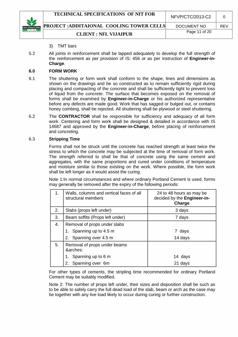
Note 1:In normal circumstances and where ordinary Portland Cement is used, forms may generally be removed after the expiry of the following periods:
1. Walls, columns and vertical faces of all structural members
24 to 48 hours as may be decided by the Engineer-in-
Charge 2. Slabs (props left under) 3 days 3. Beam soffits (Props left under) 7 days 4. Removal of props under slabs 1. Spanning up to 4.5 m 7 days 2. Spanning over 4.5 m 14 days
5. Removal of props under beams &arches:
1. Spanning up to 6 m 14 days 2. Spanning over 6m 21 days
For other types of cements, the stripling time recommended for ordinary Portland Cement may be suitably modified.
Note 2: The number of props left under, their sizes and disposition shall be such as to be able to safely carry the full dead load of the slab, beam or arch as the case may be together with any live load likely to occur during curing or further construction.
TECHNICAL SPECIFICATIONS OF NIT FOR NFVP/CTC/2013-C2 0
PROJECT :ADDITAIONAL COOLING TOWER CELLS DOCUMENT NO REV
CLIENT : NFL VIJAIPUR Page 12 of 20
7.0 BRICK WORK
This specification covers the construction of brick masonry in foundations, arches, walls, etc. at all elevations. The provision of IS: 2212 shall be complied with unless permitted otherwise.
7.1 Bricks
All bricks shall be of best locally available make and approved by PMC/OWNER Minimum compressive strength shall be 50 Kg/cm2.
7.2 Mortar
7.2.1 Cement and water shall conform to the requirements laid down for cement concrete work.
7.2.2 Sand for masonry mortar shall be coarse sand conforming to IS: 2116. Maximum quantities of clay, fine dust shall not be more than 5% by weight. Organic impurities shall not exceed the limits laid down in IS: 2116.
7.2.3 Mix of mortar for building brick work shall be 1:6 (1 Cement : 6 Coarse sand).
7.2.4 Mixing of mortar shall be done in a mechanical mixer. When quantity involved is small, hand mixing may be permitted by the Engineer-in-Charge. Any mortar remaining unused for more than 30 minutes after mixing shall be rejected.
7.2.5 All masonry work shall be constructed in 1:6 cement sand mortar except half brick partition walls which shall be constructed in 1:4 cement sand mortar with 8Tor/ M.S bars, provided at every fourth course properly anchored with cross walls or pillars.
7.3 Brick Masonry
Brick work shall be built in English bond, unless otherwise specified. The thickness of joints shall be 10 mm + 3 mm. Thickness of joints shall be kept uniform. In case of foundations and manholes etc. Joints up to 15 mm may be accepted.
7.4 Half Brick Masonry
All courses shall be laid with stretchers. Reinforcement comprising 2 Nos.6/8 mm dia MS bars shall be provided over the top of the first course and thereafter at every third course.
7.5 Fixtures
All iron fixtures, pipe spouts, hold fasts of doors and windows, which are required to be built into the wall shall be embedded in cement concrete blocks 1:2:4 mix (1 cement : 2 coarse sand : 4 graded stone aggregate 20 mm nominal size) of size indicated in the item.

TECHNICAL SPECIFICATIONS OF NIT FOR NFVP/CTC/2013-C2 0
PROJECT :ADDITAIONAL COOLING TOWER CELLS DOCUMENT NO REV
CLIENT : NFL VIJAIPUR Page 13 of 20
7.6 Curing
Brick work shall be protected from rain by suitable covering when the mortar is green. Masonry work shall be kept constantly moist on all faces for a minimum period of seven days.
8.0 STRUCTURAL STEEL WORK This specification covers the technical requirements for the preparation of shop drawings, supply, fabrication, protective coating, painting and erection of all structural steel rolled sections, built up sections, plates and miscellaneous steel required for the completion of the work.
8.1 Steel All structural steel used in construction within the purview of this contract shall, comply with one of the following Bureau of Indian Standard Specifications, whichever, is appropriate or as specified.
IS – 2062 Hot rolled sections and plates
IS – 1079 Cold formed light gauge sections
IS – 1161 Tubular sections
IS – 4923 Hollow sections (rectangular or square)
8.2 Fabrication Fabrication of steel structure shall be carried out in conformity with the best modern practices and with due regard to speed with economy in fabrication and erection and shall conform to IS-800. All members shall be so fabricated as to assemble the members accurately on site and erect them in correct positions. Before dispatch to site the components shall be assembled at shop and any defect found rectified. All members shall be free from kink, twist, buckle, bend, open joints etc. and shall be rectified before erecting in position. Failure in this respect will subject the defective members to rejection.
8.3 Fabrication Drawings 8.3.1 Fabrication and erection drawings shall be prepared by the CONTRACTOR on the
basis of design issued to the CONTRACTOR in stages. These drawings shall be prepared by the CONTRACTOR or by an agency approved by the Engineer-in-Charge.
8.3.2 Fabrication drawings shall be thoroughly checked, stamped "checked" and signed by the CONTRACTOR's own responsible Engineer irrespective of the fact that such drawings are prepared by the CONTRACTOR or an approved agency, to ensure accuracy and correctness of the drawings. Unchecked or unsigned drawing shall not be submitted to Engineer-in-Charge for approval.
8.3.3 Fabrication drawings duly checked by the CONTRACTOR shall be submitted to the Engineer-in-Charge for checking & approval within 30 days from receipt of design drawings.
8.3.4 The approval accorded by Engineer-in-Charge on fabrication drawings shall not relieve the CONTRACTOR of the responsibility of fabricating and erecting safe and technically sound steel structures as per design drawings.
TECHNICAL SPECIFICATIONS OF NIT FOR NFVP/CTC/2013-C2 0
PROJECT :ADDITAIONAL COOLING TOWER CELLS DOCUMENT NO REV
CLIENT : NFL VIJAIPUR Page 14 of 20
8.3.5 Fabrication drawings shall be drawn to a suitable scale large enough to convey the
information clearly and shall include the following:
1. Reference to design drawing number (along with revision number) based on which fabrication drawing has been prepared.
2. Structural layout plans, elevations, & sections with distinct erections, & sections with distinct erection marking of all members.
3. Framing plans, member sizes, orientations. 4. Fabrication detail of each and every member. 5. Details of Shop / field joints, connections and splices. 6. Location, type and size of welds and bolts. 7. Shape and size of edge preparation for welding. 8. Bill of material including bolts for connections.
8.3.6 The CONTRACTOR shall however ensure accuracy of the following and shall be solely responsible for the same:
1. Provision for erection and erection clearance. 2. Marking of members. 3. Cut length of members. 4. Matching of joints and holes. 5. Provision kept in the members for other interconnected members. 6. Bill of materials.
8.3.7 Connections, splices and other details where not shown on the design drawings shall be suitably designed and shown on the fabrication drawings based on good Engineering practice, developing full member strength.
8.3.8 The CONTRACTOR shall incorporate all the revisions in his fabrication drawings resulting from revision in design drawings during the course of execution of work at no extra cost.
8.3.9 The CONTRACTOR shall supply three (3) prints of each fabrication drawing submitted for checking to Engineer-in-Charge. After approval of fabrication drawings CONTRACTOR shall supply six (6) prints and two (2) reproducible of each approved fabrication drawing to Engineer-in-Charge. The rates quoted by the CONTRACTOR shall include the same.
8.4 Welding Welding shall be adopted in most of the cases for fabrication of steel structure. Welding work shall be carried out as shown in relevant drawings as per IS-816 or as required and approved by the Engineer-in-Charge. Welding of joints shall be so arranged that the resulting tensile and compressive stresses produced by each part of weld tend to balance each other.
The step back method of welding shall be adopted for continuous runs. Members which offer greater resistance to compression shall be welded first. The work shall be securely held in position by means of tack weld, clamps or jig before commencing of welding work so as to prevent relative movement due to distortion or other cause. All welds with blow holes, slag-intrusion and other defects must be removed from each run before another run is super imposed and also from the final run. Any defects in the work shall be rectified by the CONTRACTOR at his own expense. Bends, twists or distortion caused in any member due to faulty workmanship and method adopted
TECHNICAL SPECIFICATIONS OF NIT FOR NFVP/CTC/2013-C2 0
PROJECT :ADDITAIONAL COOLING TOWER CELLS DOCUMENT NO REV
CLIENT : NFL VIJAIPUR Page 15 of 20
during welding or in transit will be rejected and will have to be replaced / rectified by the CONTRACTOR at his own expense. According to the size of electrodes used, the CONTRACTOR is expected to adjust the current rating in the welding generators.
8.5 The Engineer-in-Charge reserves the right to have test done at any time for any welding and the cost of the test shall be borne by the CONTRACTOR.
8.6 Wherever continuous plates are used in built up member such as girders, columns, etc. the continuity of such plates shall be first ensured by full strength butt joints before welding such plates with the main member to form part of the built-up member.
8.7 All connection / joints made in shop shall wherever possible be welded connections and connections / joints made at site shall be bolted connections / site welded connections, continuous welding shall be done for all box members even if it is not required from design point of view.
8.8 Electrodes Electrodes used for welding shall comply with IS-814 or IS - 815 or any specification provided to the CONTRACTOR from time to time. No electrodes remaining in open containers for more than 72 hours shall be used.
8.9 No welder shall be employed to carry out welding in any position except those who are fully qualified to weld in that position as per IS -7318, part-1 qualifying tests for metal arc welders. Welders employed shall be required both before commencing work and at intervals during the progress of work to make test pieces as laid down in IS -817 and 7318, part-1 for the purpose of grading of welders and according to the said grading, welders will be employed on jobs. Welders are to be got approved by Engineer-in-Charge before engaging on work.
8.10 MS Black/High Strength Bolts and Nuts M.S.Black or high strength bolts, nuts and washers etc. shall be as per IS-800, IS-1363 and IS-1367. Manufacturer's test certificate shall be made available to the Engineer-in-Charge. For bolted joints, shanks and threaded bolts are to be used to ensure that threaded length do not encroach within the thickness of connected members of dimension beyond the following limit:-
1. 1.5 mm for connected members of thickness below 12 mm and
2. 2.5 mm for connected member of thickness 12 mm and above and that adequate shearing and bearing values required as per design are achieved.
9.0 PAINTING ON STRUCTURAL STEEL The following specification shall be used for painting of structural steel work.
9.1 Scope This specification shall be used in non coastal area & coastal area.
Surface Preparation The surfaces to be painted shall be sand blasted to Sa - 2.5 as per Swedish Standard SIS 05-59-00. Air used for sand blasting must be dry and oil free. Sand used for sand blasting shall be good quality river sand suitable for achieving the required surface finish. For optimum results pressure of sand blasting gun should be maintained at around 7 kg/cm2 and maximum height of profile should be kept around 50 microns. Sand blasted surfaces must be coated with primer within 4 hrs in dry

TECHNICAL SPECIFICATIONS OF NIT FOR NFVP/CTC/2013-C2 0
PROJECT :ADDITAIONAL COOLING TOWER CELLS DOCUMENT NO REV
CLIENT : NFL VIJAIPUR Page 16 of 20
climate. Moreover it is not advisable to carry out sand blasting when humidity exceeds 85% (RH).
9.1.1 Painting system to be used are indicated below: 1. Epoxy Painting:
Primer P 1-2 coats + finish paint FP1 (2 coats) where P1 is epoxy polyamide cured zinc chromate primer having DFT of 35 micron per coat and FP1 is epoxy polyamide cured finish paint having DFT (Dry Film Thickness) of 35 micron per coat.
Equivalent product chart for approved paint manufactures for primer P1 finish paint FP1 indicated above is enclosed.
9.1.2 All the surfaces must be sand blasted and 2 coats of primer plus 1 coat of finish paint applied in the shop before the same are shifted to site for erection. All the members must be suitably match marked for facilitating proper assembly.
After erection is over all surfaces shall be washed up as follows:
1. Washing with clean water (pressure 7 kg/cm2) using suitable nozzles. During washing broom corn brushes shall be used to remove foreign matters.
2. Solvent washing if required to remove traces of oil grease etc.
3. After washing the surface as indicated above, the surfaces shall be suitably touched up to the extent required so that all the damages to the premiered surfaces caused during erection are done up.
The surfaces affected by welding and / or gas cutting during erection shall also be suitably touched up. Before touch up is taken up surfaces shall be prepared by mechanical means such as grinding, power brushing etc. to achieve surface finish to ST-3.
After touch up work is over as indicated above, all the surfaces shall be given one coat of finish paint to the required specification.
9.1.3 The following points must be observed for painting work:
1. Primer and paint shall be compatible to each other and should be from the same manufacturer.
2. The recommendation of the paint manufacturer regarding mixing, matching and application must be followed meticulously.
3. Technical representative of paint manufacturer should be available at site as and when required by Engineer-in-Charge for their expert advice as well as to ensure that the painting work is executed as per the instruction of paint manufactures.
Paints and primers shall be supplied at site in original container with factory seal otherwise such paints and primers shall not be allowed to be used. Mode of application i.e. by spray, brush or roller shall be strictly as per recommendation of paint manufacturer.
Painting materials must be used before the expiry date indicated on the containers.

TECHNICAL SPECIFICATIONS OF NIT FOR NFVP/CTC/2013-C2 0
PROJECT :ADDITAIONAL COOLING TOWER CELLS DOCUMENT NO REV
CLIENT : NFL VIJAIPUR Page 17 of 20
Number of coats and DFT per coat must be strictly followed as indicated above. If the desired DFT is not achieved for primer and finish paints in two coats (each), CONTRACTOR shall be required to apply extra coat (s) to achieve the desired DFT without any extra cost to Engineer-in-Charge.
Colour shade for each coat of primer and finish paint must be different to identify the coats without any ambiguity.
Shade for the final finish coat shall be decided by Engineer-in-Charge at site.
All painting materials must be accompanied by manufacturers test certificates. However, Engineer-in-Charge has any doubt regarding quality of materials, he shall have the right to direct CONTRACTOR to get the doubtful material tested or and provided (by CONTRACTOR) testing agencies for which no extra payment shall be made to the CONTRACTOR and the charges shall deemed to be covered in the unit rates quoted for fabrication and erection of structural work.
DFT for paint shall be measured at least 20 points and mean DFT shall not vary by more than 10% than specified in DFT.
Instrument for measurement of DFT shall be arranged and provided by CONTRACTOR at his cost.
Thickness of each coat shall also be checked regularly to ensure uniformity in DFT.
9.1.4 Sand blasting and painting works, being a specialized job must be carried out through the approved agencies only.
9.1.5 Equivalent Chart for Various Paint Manufacturers for Epoxy paint
ASIAN G & N SHALIMAR J & N BERGER BOMBAY P1 APCODUR -
Epoxy Zinc Chrome Primer
AMERCOAT-71
EPIGARD-4 Zinc Chromate Primer
EPILAC Zinc Chromate Primer
EPILUX-4 Zinc Chromate Primer
PENTADUR PRIMER 1532
FP1 APCODUR CF 692
NEROLAC TWO COMP EPOXY
EPIGARD XL FINISH
EPILAC 974 ENAMEL
EPILUX-4 ENAMEL
PENTADUR ENAMEL 5534 GRAY
10.0 STEEL / ALUMINIUM DOORS, WINDOWS AND VENTILATORS 10.1 The Steel doors, windows and ventilators shall be of the size and type as perIS-1361
and IS-1038. Fixing and glazing shall be done as per IS-1081 and as per manufacturer’s instructions. The putty of approved make such as special gold size or equivalent conforming to IS-419 shall be used.
10.2 Aluminium doors, windows and ventilators shall be manufactured from wrought aluminium and aluminium alloy extruded round tube and / or hollow rectangular / square sections conforming to IS: 1285 &IS : 6477 or equivalent as approved by Engineer-in-Charge.

TECHNICAL SPECIFICATIONS OF NIT FOR NFVP/CTC/2013-C2 0
PROJECT :ADDITAIONAL COOLING TOWER CELLS DOCUMENT NO REV
CLIENT : NFL VIJAIPUR Page 18 of 20
11.0 FLOORING AND PAVING 11.1 Sub Base of floor 11.1.1 The area to be paved shall be divided into suitable panels. Form work shall be
provided. The boarding / battens shall be fixed in position with their toe at proper level, giving slope where required. Alternatively base concrete may be deposited in the whole area at a stretch.
11.1.2 Before placing the base concrete the sub-base shall be properly wetted and rammed. The concrete of the specified mix shall then be deposited between the forms where provided, thoroughly tamped and the surface finished level with the top edge of the forms. The surface of base concrete shall be spreader uniformly. The surface shall be finished rough to provide adequate bond for the topping. Two or three hours after concrete has been laid the surface shall be brushed with wire brush to remove any scum or Latinate and swept clean so that coarse aggregate is exposed.
11.2 Cement Concrete Floor Finishes 11.2.1 The surface of base concrete shall be thoroughly cleaned by scrubbing with coir or
steel wire brush. Before laying the toping, the surface shall be soaked with water at least for 12 hours and surplus water mopped up immediately before the toping is laid.
11.2.2 The forms shall be fixed over the base concrete dividing into suitable panels. Where glass dividing strips are provided, thickness of glass dividing strips shall be 4 or as indicated. Before placing the concrete toping, neat cement slurry at the rate of 2 kg/sq.m shall be then thoroughly brushed into the base concrete just ahead of the finish. The topping shall then be laid, thoroughly compacted by using screed board/plate vibrator. The surface floated with a wooden float to a fair and even surface shall be left for some time till moisture disappears from it. Junctions with skirting / dado or wall surfaces shall be rounded off using cement mortar 1:2 curing shall be carried out for a minimum of 7 days.
12.0 PLASTERING 12.1 Sand for plastering shall be 50% fine sand and 50% coarse sand from approved
sources.
12.2 Preparation of surface shall be done as per CPWD specifications.
12.3 Cement mortar shall be of the mix 1:6 (1 Cement : 6 Sand ) and shall be mixed as specified in the CPWD specifications.
12.4 Joints in walls etc. shall be raked to a depth of 12 mm, brushed clean with wire brushes dusted and thoroughly washed before starting the plaster work.
12.5 The surface shall be thoroughly washed with water cleaned and kept wet to saturation point before plastering is commenced.
12.6 Cement mortar as indicated, shall be firmly applied to the masonry walls in a uniform layer to the thickness specified and will be pressed into the joints. On concrete surfaces rendering shall be dashed to the roughened surface to ensure adequate bond. The surface shall be finished even and smooth. Hectoring wherever required shall be done as per directions of Engineer-in-Charge. Nothing extra shall be paid on this account.
12.7 All plaster work shall be cured for at least 7 days.
12.8 Integral water proofing compound shall be mixed with cement in the proportion recommended by the manufacturer. Care shall be taken to ensure that the water

TECHNICAL SPECIFICATIONS OF NIT FOR NFVP/CTC/2013-C2 0
PROJECT :ADDITAIONAL COOLING TOWER CELLS DOCUMENT NO REV
CLIENT : NFL VIJAIPUR Page 19 of 20
proofing material gets well and integrally mixed with cement. All other operations are the same as for general plaster work.
12.9 For sand face plaster undercoat of cement plaster 1:4 (1 cement : 4 sand) of thickness not less than 12 mm shall be applied similar to one coat plaster work. Before the under coat hardens the surface shall be scared to provide for the top coat. The top coat also of cement mortar 1:4 shall be applied to a thickness not less than 8 mm and brought to an even surface with a wooden float. The surface shall then be tapped gently with a wooden float lined with cork to retain a coarse surface texture, care being taken that the tapping is even and uniform.
13.0 EXTERIOR PAINTING OR APEX 13.1 Exterior painting shall be Apex of “Asian Paint” or equivalent.
13.2 Where shown on drawings for external surfaces of sand faced plaster, or any other surface, two coats of cement paint shall be applied of tint and shade as approved by the Engineer-in-Charge.
13.3 The surfaces shall be prepared as specified for white washing. Before applying cement paint the surface shall be thoroughly wetted to control surface suction. The surface shall be moist but not dripping wet, when the paint is applied. Not less than 24 hours shall be allowed between the two coats. In hot weather the first coat shall be slightly moistened before applying the second coat.
13.4 On external plastered surfaces (one coat primer + minimum 3 coat of paints), sand faced or plain plastered and concrete surfaces, apex weather proof paint shall be vigorously scrubbed on to work the paint into the voids and provide a continuous paint film free from pin holes and other openings.
14.0 GLAZING 14.1 Sheet glass glazing of doors, windows etc. shall be of selected quality glass
conforming to IS: 2835. Toughened splinter proof industrial safety glass shall confirm to IS: 2553. No cracked chipped or disfigured glass shall be accepted Glass shall be in one piece for each pan.
14.2 Glazing shall be fixed with timber or steel / aluminium beading as called for. Glass shall be back puttied and fixed with beading for a water tight and rattle free installation. Sizes of timber/ steel / aluminium beading shall be as directed.
15.0 STORM WATER DRAINS
15.1 The covered precast slab storm water drains shall be of the size and laid to such gradients and in such locations as may be shown in the approved drawings or as directed by the Engineer-in-Charge. The sides and bottom of the drain or the sides and top of embankment, as the case may be, shall be brought to the required profile, slope and gradient and shall be compacted to a firm and even surface. If the situation demands, and where so required by the Engineer-in-Charge in consideration of the nature of the surface, the necessary back filling may be done with small broken stone, moorum, gravel or ballast well consolidated to proper profile. In case the soil is

TECHNICAL SPECIFICATIONS OF NIT FOR NFVP/CTC/2013-C2 0
PROJECT :ADDITAIONAL COOLING TOWER CELLS DOCUMENT NO REV
CLIENT : NFL VIJAIPUR Page 20 of 20
unreliable and if the nature of the work requires it a 75 mm. thick layer of gravel or ballast may be provided over the prepared surface and well consolidated. In the case of embankments of large heights, suitable design of pitching etc., should be worked out and special specifications framed in each case.
16.0 REFERENCE DRAWINGS
1) EM65-0000-0201 - Standard details for grade slab and pavement
2) EM65-0000-0202 - Standard details for gratings
3) EM65-0000-0202 - Standard details for platforms, handrails & cat-ladders.
DEMOLITION & DISMANTLING WORK
NEW COOLING TOWER CELL
NFVP/CTC/2013-C3 0
DOCUMENT NO. REV SHEET 1 OF 7
ANNEXURE C3
DEMOLITION & DISMANTLING WORK

DEMOLITION & DISMANTLING WORK
NEW COOLING TOWER CELL
NFVP/CTC/2013-C3 0
DOCUMENT NO. REV
SHEET 2 OF 7
FORM NO: 02-0000-0021F2 REV2 All rights reserved
TABLE OF CONTENTS
SL. NO. DESCRIPTION PAGE NO. 1.0 SCOPE 3 1.1 DEMOLITION 3 1.2 DISMANTLING 3 2.0 APPLICABLE CODES 3 3.0 PRIORITY OF REQUIREMENT 3 4.0 GENERAL 4 5.0 SAFETY PRECAUTIONS 4 6.0 PROCEDURES 5 7.0 CLEANING & STACKING 5 8.0 DISPOSAL 6 9.0 PAYMENT 6
10.0 DISMANTLING OF ROOF SHEETING AND WALL CLADDING
6
11.0 DISMANTLING OF STRUCTURAL STEEL WORKS
6
12.0 DEMOLITION OF REINFORCED CONCRETE AND BRICK WORKS
7
13.0 CHIPPING OF CONCRETE SURFACES 7 14.0 WALLS AND PIERS 7 15.0 EXCAVATION AND BACKFILLING 8
DEMOLITION & DISMANTLING WORK
NEW COOLING TOWER CELL
NFVP/CTC/2013-C3 0
DOCUMENT NO. REV
SHEET 3 OF 7
FORM NO: 02-0000-0021F2 REV2 All rights reserved
1.0 SCOPE
This specification defines the procedure and safety requirements for demolition and dismantling of reinforced concrete, plain concrete, brick masonry, stone masonry, structural steel (sheeted / unsheeted) work, various finishing items (false flooring, false ceiling, doors, windows, etc.) or any such other work. Any special requirement as shown or noted on the drawing shall govern the provision of this specification.
1.1 Demolition
The term demolition implies breaking up. This shall consist of demolishing whole or part of work including all relevant items as specified or shown on the drawings.
1.2 Dismantling
The term dismantling implies removing without damage. This shall consist of dismantling one or more part of the building as specified or shown on the drawings.
2.0 Applicable Codes
Note: Wherever reference is made to IS Codes, on any page of this Technical Specification (including Annexure), applicable year of publication of IS Code is as stated below.
The Indian Standard codes applicable to this section shall include but not limited to the following:
IS 808-1989 : Dimensions of hot rolled steel beam, column, channel and angle sections.
IS 1200-1974 : Method of measurement of building and civil engineering works, demolition and dismantling (Part XVIII).
IS 4081-1986 : Safety code for blasting and related drilling operations.
IS 4130-1991 : Safety code for demolition of buildings.
IS 4138-1977 : Safety code for working in compressed air.
IS 7293-1974 : Safety code for working with construction machinery.
3.0 PRIORITY OF REQUIREMENTS
In case of any variation and discrepancy in condition between the special conditions, this specifications and codes, order of priority shall be as under:-
(1) Special Conditions
(2) This specifications
(3) Codes
DEMOLITION & DISMANTLING WORK
NEW COOLING TOWER CELL
NFVP/CTC/2013-C3 0
DOCUMENT NO. REV
SHEET 4 OF 7
FORM NO: 02-0000-0021F2 REV2 All rights reserved
4.0 GENERAL
4.1 Apart from this specification, the demolition and dismantling of structures (part or whole) shall be in compliance with all statutory safety regulations and any other special requirement as shown/ noted on the drawings und General Conditions of Contract. Prior approval of the OWNER/ Engineer-In-Charge shall be obtained before starting any dismantling works. Any restrictions imposed regarding working hours shall also be strictly followed by the CONTRACTOR.
4.2 All materials obtained from dismantling/ demolition operations shall be the property of the OWNER unless otherwise specified and shall be kept in safe custody until handed over to the Engineer-ln-Charge.
4.3 Where it becomes necessary to disconnect any existing service lines (such as electrical, piping etc.) during dismantling / demolishing operation and where so required by the Engineer-In-Charge, suitable alternate arrangement shall be made by the CONTRACTOR to maintain the continuity and proper functioning of the affected service lines with the approval of the Engineer-In-Charge at no extra cost to the OWNER/PMC.
5.0 SAFETY PRECAUTIONS
5.1 The CONTRACTOR shall adhere to safe demolishing / dismantling practices at all stages of work to guard against accidents, hazardous and unsafe working procedures.
5.2 Necessary propping, shoring, strutting and/ or under-pinning shall be provided for the safety of the adjoining work or property (whose safety is likely to be endangered) before dismantling and demolishing is taken up. The work shall be carried out in such a way that no damage is caused to the adjoining work or property.
5.3 Temporary enclosures made out of GI sheet fencing, danger lights, etc. shall be provided by the CONTRACTOR at his own cost and get approved by Engineer-In--Charge before start of work.
5.4 Necessary precautions shall be taken to keep the dust and noise nuisance to minimum levels.
5.5 Dismantling shall be done in a systematic manner. All materials, which are likely to be damaged by dropping from a height or demolishing roofs, masonry etc., shall be carefully removed first. The dismantled articles shall be passed by hand, where necessary, lowered to the ground (and not dropped from a height or thrown from a distance) and then properly stacked as directed by the Engineer-In-Charge.
5.6 Dismantling of elements fixed by screws/ bolts/ hooks etc. shall be done by taking out the fixtures with proper tools only. Such fixtures may be allowed to be cut by sawing or flame cutting, in the event of their being stuck up due to corrosion etc. However the decision of Engineer-In-Charge in this regard shall be final and binding. Welds shall be

DEMOLITION & DISMANTLING WORK
NEW COOLING TOWER CELL
NFVP/CTC/2013-C3 0
DOCUMENT NO. REV
SHEET 5 OF 7
FORM NO: 02-0000-0021F2 REV2 All rights reserved
removed by flame cutting. Tearing or ripping of elements shall not be resorted to under any condition.
5.7 The CONTRACTOR shall maintain disconnected services whether temporary or permanent, if required.
5.8 CONTRACTOR must ensure the availability of adequate firefighting equipment/ arrangements before starting actual demolishing / dismantling works. These facilities shall be made available throughout the entire operation of demolition and dismantling of structures at his own cost.
5.9 All equipments, pipes, fittings and instruments, underground utilities etc; located in the vicinity shall be protected by suitable means, as instructed by the Engineer-In-Charge, during demolishing, dismantling operations. The cost of these protections shall be considered by the CONTRACTOR.
5.10 Roads and working spaces shall be kept free of any debris/dismantled materials at the end of day's work.
6.0 PROCEDURES
6.1 Method of Dismantling and Demolition
Various methods and suitable means and materials may be listed as approved by the Engineer-In-Charge and as described below:
(i) Controlled blasting with explosives as per IS 4081. (ii) Using compressed air equipments as per IS 4138. (iii) By Mechanical means viz. Drilling, Chiseling, hammering, etc. (iv) By using “Acconex” – non explosive material manufactured by Associated Cement
co. Ltd. R&D Group, Thane and as per their Specifications and Instructions.
6.2 Demolition and dismantling shall be restricted to the extent shown on drawings or as directed by the Engineer-In-Charge.
6.3 The demolition shall always be planned before hand and shall be done in reverse order of the one in which the structure was constructed. The scheme shall be got approved from the Engineer-In-Charge before starting the work.
6.4 Chipping of concrete/ grout shall be done with precision by chiseling. The finished surfaces shall be made true to the requisite size and shape.
6.5 Pockets/holes of specified size shall be made/cut by drilling/chiseling.
7.0 CLEANING AND STACKING
All demolished / dismantled serviceable materials such as bricks, stones, reinforcement bars Structural steel, sheeting etc. shall be separated outs, cleaned and stacked in separate lots within the plant boundary and as directed by the Engineer-In-Charge.

DEMOLITION & DISMANTLING WORK
NEW COOLING TOWER CELL
NFVP/CTC/2013-C3 0
DOCUMENT NO. REV
SHEET 6 OF 7
FORM NO: 02-0000-0021F2 REV2 All rights reserved
8.0 DISPOSAL
All unserviceable materials shall be disposed off, dressed and leveled within or outside the plant boundary up to the required level as per the directions of the Engineer-In-Charge. Areas required outside the plant boundary for dumping of disposed material shall be arranged by the CONTRACTOR and got approved by the Engineer-In-Charge.
10.0 DISMANTLING OF ROOF SHEETING AND WALL CLADDING
The work of dismantling shall include supply of labour, tools and tackles, equipments, consumables, necessary safety measures, handling, scaffolding, unbolting, cutting (by saw or flame cutting) of hook bolts, removal of ridges, gutters, flashings, transporting, stacking of all serviceable materials etc. all completed as directed by Engineer-In-Charge.
11.0 DISMANTLING STRUCTURAL STEEL WORKS
All structural steel work shall be measured in metric tonnes (MT). The weight shall be computed from IS 808, unless the actual weight can really be determined as per the instructions of Engineer-In-Charge.
Riveted work, where rivets are required to be cut, shall be measured separately.
Marking of structural steel required to be re-erected shall be measured separately.
The work of dismantling shall include supply of labour, tools and tackles, equipment, consumables, necessary safety measures, scaffolding, propping, handling, unbolting, cutting (by sawing or flame cutting) of gussets, plates, bolts, hooks, welds, cleaning, sorting out and stacking of all serviceable materials etc. all complete as specified and directed by Engineer-In-Charge.
12.0 DEMOLITION OF REINFORCED CONCRETE AND BRICK WORKS
Reinforced concrete structures (part or whole), reinforced brick roofs and walls shall be measured in cubic meters.
Where reinforcement is required to be separated, scraped and cleaned, the work shall be measured separately in metric tonnes (MT) of salvaged steel.
The work of demolishing shall include supply of labour, tools and tackles, necessary safety measures, propping, underpinning, scaffolding, handling, cutting, straightening, scraping and cleaning of reinforcement bars and other embedment (in case of reinforced concrete works), sorting out and stacking of all serviceable materials, disposal of all unserviceable material, clearing the site, etc. all complete as specified and directed by the Engineer-In-Charge.
DEMOLITION & DISMANTLING WORK
NEW COOLING TOWER CELL
NFVP/CTC/2013-C3 0
DOCUMENT NO. REV
SHEET 7 OF 7
FORM NO: 02-0000-0021F2 REV2 All rights reserved
In measuring thickness of roofs provided with water proofing treatments, the thickness of water proofing treatment shall be ignored.
13.0 CHIPPING OF CONCRETE SURFACES
The work of chipping shall include supply of labour, tools and tackles, necessary safety measures, scaffolding, chiseling, handling exposing, cutting, straightening, scraping, clearing the reinforcement bars (in case of reinforced concrete works), wire brushing and washing the exposed surfaces, disposal of all unserviceable materia1 etc. all complete as directed by Engineer-In-Charge.
14.0 WALLS AND PIERS
Taking down walls and independent piers or columns of brick, stone or concrete shall be measured in cubic meters (m3). All copings, corbels, cornices and other projections shall be included with the wall measurements. In measuring thickness of plastered walls, the thickness of plaster shall be ignored.
Ashlar face stones, dressed stone work, precast concrete articles etc. if required to be taken down, shall be measured separately in cubic meters (m3).
Cleaning bricks, stacking for measurements including all extra handling and removal and disposing rubbish as stated shall be measured in cubic meters (m3) of cleaned bricks.
Cleaning stone, obtained from demolished stone masonry of any description including ashlar facing, dressed stone work, stone slabs or flagging and precast concrete blocks including all extra handling and disposing of rubbish as stated shall be measured in cubic meters (m3) of cleaned stone.
Honey comb work or cavity walls of bricks, stone or concrete shall be measured as solid.
15.0 EXCAVATION AND BACKFILLING
Excavation and backfilling shall be laid separately as per relevant clauses of Technical specification for civil, structural & allied works (Annexure-V)

NATIONAL FERTILIZER LIMITED, VIJAIPUR
STANDARD FOR GRATINGS
PC65-0000-0202 P
DOC. NO. REV.
SHEET 1 of 5
FORM NO: 02-0000-0021F3 REV3 All rights reserved
STANDARD
FOR
GRATINGS
FOR
NFL VIJAIPUR
P 26.06.2013 ISSUED FOR TENDER TP SA RVV REV REV DATE PURPOSE PREPD REVWD APPD