Embed Size (px)
Citation preview
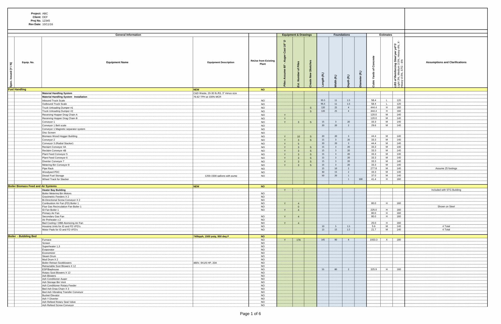
Project: ABC
Client: DEF
Proj No. 12345
Rev Date: 10/11/16
Sp
ec
. Is
su
ed
(Y
/ N
) Equip. No. Equipment Name Equipment DescriptionReUse from Existing
Plant
Pile
s A
ss
um
e 6
0' -
Au
ge
r C
as
t 1
6" D
Es
t. N
um
be
r o
f P
ile
s
Cre
ate
Ne
w S
ke
tch
es
Le
ng
th (
ft.)
Wid
th (
ft.)
De
pth
(ft
.)
Dia
me
ter
(ft.
)
Cu
bic
Ya
rds
of
Co
nc
rete
LB
S o
f R
ein
forc
ing
Ste
el p
er
yd
^3
Lig
ht 3
%, M
ed
ium
3.5
%, H
ea
vy 4
%, X
-
He
avy 4
.5%
, S
TG
- 6
%
Assumptions and Clarifications
NEW NO
Material Handling System C&D Waste, 20-30 lb./ft3, 3" minus size
Material Handling System Installation 76.62 TPH at 100% MCR
Inbound Truck Scale NO 95.5 11 1.5 58.4 L 120
Outbound Truck Scale NO 95.5 11 1.5 58.4 L 120
Truck Unloading Dumper #1 NO S 120 25 4 444.4 H 160
Truck Unloading Dumper #2 NO S 120 25 4 444.4 H 160
Receiving Hopper Drag Chain A NO Y 120.0 M 140
Receiving Hopper Drag Chain B NO Y 120.0 M 140
Conveyor 1 NO Y 3 S 15 3 20 33.3 M 140
Conveyor 1 Belt scale NO 20 20 2 29.6 M 140
Conveyor 1 Magnetic separator system NO
Disc Screen NO
Biomass Wood Hogger Building NO Y 10 S 20 20 3 44.4 M 140
Conveyor 2 NO Y 3 S 15 3 20 33.3 M 140
Conveyor 3 (Radial Stacker) NO Y 5 20 20 3 44.4 M 140
Reclaim Conveyor 4A NO Y 3 S 15 3 20 33.3 M 140
Reclaim Conveyor 4B NO Y 3 S 15 3 20 33.3 M 140
Plant Feed Conveyor 5 NO Y 3 S 15 3 20 33.3 M 140
Plant Feed Conveyor 6 NO Y 3 S 15 3 20 33.3 M 140
Diverter Conveyor 7 NO Y 3 S 15 3 20 33.3 M 140
Metering Bin Conveyor 8 NO Y 3 S 15 3 20 33.3 M 140
Pipe Rack NO 15 10 2 277.8 M 140 Assume 25 footings
Woodyard PDC NO 30 15 2 33.3 M 140
Diesel Fuel Storage 1200-1500 gallons with pump NO 50 20 1 37.0 M 140
Wheel Track for Stacker 1 100 41.4 H 160
NEW NO
Heater Bay Building Y - Included with STG Building
Boiler Metering Bin Motors NO
Gravimetric Feeders X 2 NO
Bi-Directional Screw Conveyor X 2 NO
Combustion Air Fan (FD) Boiler 1 NO Y 4 80.0 H 160
Flue Gas Recirculation Fan Boiler 1 NO 0 Shown on Steel
ID Fan Boiler 1 NO Y 4 225.0 H 160
Primary Air Fan 80.0 H 160
Secondary Gas Fan NO Y 4 80.0 H 160
Air Preheater x 2 NO
Bed Cooling / OBB Atomizing Air Fan NO Y 4 25.0 H 160
Housing Units for ID and FD VFD's NO 10 5 1.5 5.6 M 140 4 Total
Motor Pads for ID and FD VFD's NO 13 15 1.5 21.7 M 140 4 Total
740kpph, 1500 psig, 950 deg F NO
Furnace NO Y 176 145 90 4 1933.3 X 180
Screen NO
Superheater 1,3 NO
Evaporator NO
Economizer NO
Steam Drum NO
Mud Drum X 2 NO
Boiler Retract Sootblowers 480V, 9X1/6 HP, 20A NO
Retractable Soot Blowers X 12 NO
ESP/Baghouse NO 55 80 2 325.9 H 160
Rotary Soot Blowers X 12 NO
Ash Blowers NO
Ash Conditioner Auger NO
Ash Storage Bin Vent NO
Ash Conditioner Rotary Feeder NO
Bed Ash Drag Chain X 3 NO
Bed Ash Vibrating Transfer Conveyor NO
Bucket Elevator NO
Ash Y Diverter NO
Ash Refeed Rotary Seal Valve NO
Ash Refeed Screw Conveyor NO
Equipment & Drawings Foundations Estimates
Boiler Biomass Feed and Air Systems
Fuel Handling
General Information
Boiler - Bubbling Bed
Page 1 of 6
Project: ABC
Client: DEF
Proj No. 12345
Rev Date: 10/11/16
Sp
ec
. Is
su
ed
(Y
/ N
) Equip. No. Equipment Name Equipment DescriptionReUse from Existing
Plant
Pile
s A
ss
um
e 6
0' -
Au
ge
r C
as
t 1
6" D
Es
t. N
um
be
r o
f P
ile
s
Cre
ate
Ne
w S
ke
tch
es
Le
ng
th (
ft.)
Wid
th (
ft.)
De
pth
(ft
.)
Dia
me
ter
(ft.
)
Cu
bic
Ya
rds
of
Co
nc
rete
LB
S o
f R
ein
forc
ing
Ste
el p
er
yd
^3
Lig
ht 3
%, M
ed
ium
3.5
%, H
ea
vy 4
%, X
-
He
avy 4
.5%
, S
TG
- 6
%
Assumptions and Clarifications
Equipment & Drawings Foundations Estimates
Fuel Handling
General Information
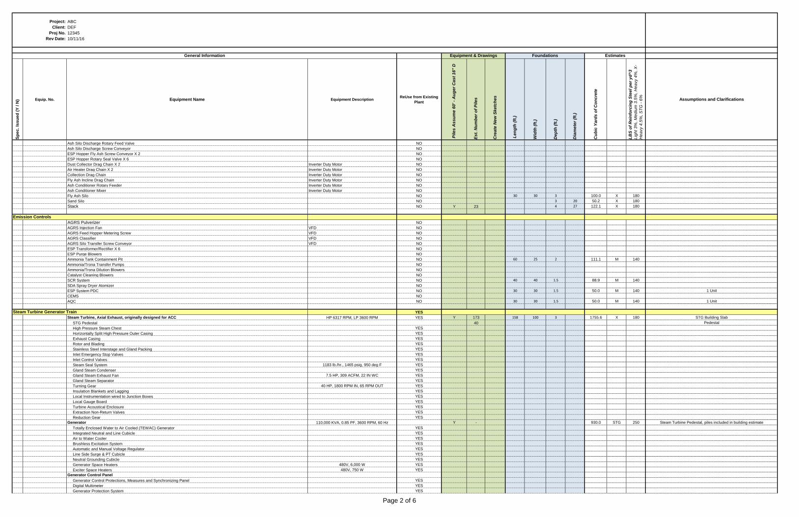
Ash Silo Discharge Rotary Feed Valve NO
Ash Silo Discharge Screw Conveyor NO
ESP Hopper Fly Ash Screw Conveyor X 2 NO
ESP Hopper Rotary Seal Valve X 6 NO
Dust Collector Drag Chain X 2 Inverter Duty Motor NO
Air Heater Drag Chain X 2 Inverter Duty Motor NO
Collection Drag Chain Inverter Duty Motor NO
Fly Ash Incline Drag Chain Inverter Duty Motor NO
Ash Conditioner Rotary Feeder Inverter Duty Motor NO
Ash Conditioner Mixer Inverter Duty Motor NO
Fly Ash Silo NO 30 30 3 100.0 X 180
Sand Silo NO 3 20 50.2 X 180
Stack NO Y 23 4 27 122.1 X 180
AGRS Pulverizer NO
AGRS Injection Fan VFD NO
AGRS Feed Hopper Metering Screw VFD NO
AGRS Classifier VFD NO
AGRS Silo Transfer Screw Conveyor VFD NO
ESP Transformer/Rectifier X 6 NO
ESP Purge Blowers NO
Ammonia Tank Containment Pit NO 60 25 2 111.1 M 140
Ammonia/Trona Transfer Pumps NO
Ammonia/Trona Dilution Blowers NO
Catalyst Cleaning Blowers NO
SCR System NO 40 40 1.5 88.9 M 140
SDA Spray Dryer Atomizer NO
ESP System PDC NO 30 30 1.5 50.0 M 140 1 Unit
CEMS NO
AQC NO 30 30 1.5 50.0 M 140 1 Unit
YES
Steam Turbine, Axial Exhaust, originally designed for ACC HP 6317 RPM, LP 3600 RPM YES Y 173 158 100 3 1755.6 X 180 STG Building Slab
STG Pedestal 40 Pedestal
High Pressure Steam Chest YES
Horizontally Split High Pressure Outer Casing YES
Exhaust Casing YES
Rotor and Blading YES
Stainless Steel Interstage and Gland Packing YES
Inlet Emergency Stop Valves YES
Inlet Control Valves YES
Steam Seal System 1183 lb./hr., 1465 psig, 950 deg F YES
Gland Steam Condenser YES
Gland Steam Exhaust Fan 7.5 HP, 309 ACFM, 22 IN WC YES
Gland Steam Separator YES
Turning Gear 40 HP, 1800 RPM IN, 65 RPM OUT YES
Insulation Blankets and Lagging YES
Local Instrumentation wired to Junction Boxes YES
Local Gauge Board YES
Turbine Acoustical Enclosure YES
Extraction Non-Return Valves YES
Reduction Gear YES
Generator 110,000 KVA, 0.85 PF, 3600 RPM, 60 Hz Y - 930.0 STG 250 Steam Turbine Pedestal, piles included in building estimate
Totally Enclosed Water to Air Cooled (TEWAC) Generator YES
Integrated Neutral and Line Cubicle YES
Air to Water Cooler YES
Brushless Excitation System YES
Automatic and Manual Voltage Regulator YES
Line Side Surge & PT Cubicle YES
Neutral Grounding Cubicle YES
Generator Space Heaters 480V, 6,000 W YES
Exciter Space Heaters 480V, 750 W YES
Generator Control Panel
Generator Control Protections, Measures and Synchronizing Panel YES
Digital Multimeter YES
Generator Protection System YES
Emission Controls
Steam Turbine Generator Train
Page 2 of 6
Project: ABC
Client: DEF
Proj No. 12345
Rev Date: 10/11/16
Sp
ec
. Is
su
ed
(Y
/ N
) Equip. No. Equipment Name Equipment DescriptionReUse from Existing
Plant
Pile
s A
ss
um
e 6
0' -
Au
ge
r C
as
t 1
6" D
Es
t. N
um
be
r o
f P
ile
s
Cre
ate
Ne
w S
ke
tch
es
Le
ng
th (
ft.)
Wid
th (
ft.)
De
pth
(ft
.)
Dia
me
ter
(ft.
)
Cu
bic
Ya
rds
of
Co
nc
rete
LB
S o
f R
ein
forc
ing
Ste
el p
er
yd
^3
Lig
ht 3
%, M
ed
ium
3.5
%, H
ea
vy 4
%, X
-
He
avy 4
.5%
, S
TG
- 6
%
Assumptions and Clarifications
Equipment & Drawings Foundations Estimates
Fuel Handling
General Information
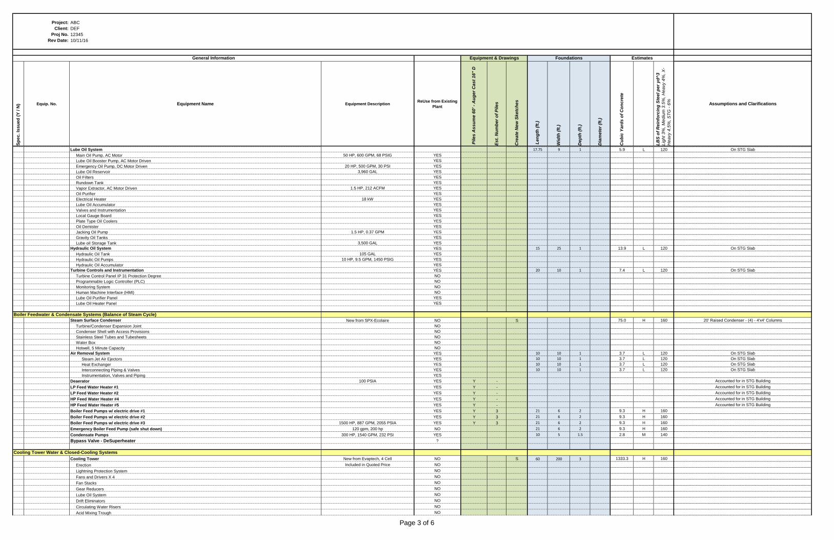
Lube Oil System 17.75 9 1 5.9 L 120 On STG Slab
Main Oil Pump, AC Motor 50 HP, 600 GPM, 68 PSIG YES
Lube Oil Booster Pump, AC Motor Driven YES
Emergency Oil Pump, DC Motor Driven 20 HP, 500 GPM, 30 PSI YES
Lube Oil Reservoir 3,960 GAL YES
Oil Filters YES
Rundown Tank YES
Vapor Extractor, AC Motor Driven 1.5 HP, 212 ACFM YES
Oil Purifier YES
Electrical Heater 18 kW YES
Lube Oil Accumulator YES
Valves and Instrumentation YES
Local Gauge Board YES
Plate Type Oil Coolers YES
Oil Demister YES
Jacking Oil Pump 1.5 HP, 0.37 GPM YES
Gravity Oil Tanks YES
Lube oil Storage Tank 3,500 GAL YES
Hydraulic Oil System YES 15 25 1 13.9 L 120 On STG Slab
Hydraulic Oil Tank 105 GAL YES
Hydraulic Oil Pumps 10 HP, 9.5 GPM, 1450 PSIG YES
Hydraulic Oil Accumulator YES
Turbine Controls and Instrumentation YES 20 10 1 7.4 L 120 On STG Slab
Turbine Control Panel IP 31 Protection Degree NO
Programmable Logic Controller (PLC) NO
Monitoring System NO
Human Machine Interface (HMI) NO
Lube Oil Purifier Panel YES
Lube Oil Heater Panel YES
Steam Surface Condenser New from SPX-Ecolaire NO S 75.0 H 160 20' Raised Condenser - (4) - 4'x4' Columns
Turbine/Condenser Expansion Joint NO
Condenser Shell with Access Provisions NO
Stainless Steel Tubes and Tubesheets NO
Water Box NO
Hotwell, 5 Minute Capacity NO
Air Removal System YES 10 10 1 3.7 L 120 On STG Slab
Steam Jet Air Ejectors YES 10 10 1 3.7 L 120 On STG Slab
Heat Exchanger YES 10 10 1 3.7 L 120 On STG Slab
Interconnecting Piping & Valves YES 10 10 1 3.7 L 120 On STG Slab
Instrumentation, Valves and Piping YES
Deaerator 100 PSIA YES Y - Accounted for in STG Building
LP Feed Water Heater #1 YES Y - Accounted for in STG Building
LP Feed Water Heater #2 YES Y - Accounted for in STG Building
HP Feed Water Heater #4 YES Y - Accounted for in STG Building
HP Feed Water Heater #5 YES Y - Accounted for in STG Building
Boiler Feed Pumps w/ electric drive #1 YES Y 3 21 6 2 9.3 H 160
Boiler Feed Pumps w/ electric drive #2 YES Y 3 21 6 2 9.3 H 160
Boiler Feed Pumps w/ electric drive #3 1500 HP, 887 GPM, 2055 PSIA YES Y 3 21 6 2 9.3 H 160
Emergency Boiler Feed Pump (safe shut down) 120 gpm, 200 hp NO 21 6 2 9.3 H 160
Condensate Pumps 300 HP, 1540 GPM, 232 PSI YES 10 5 1.5 2.8 M 140
Bypass Valve - DeSuperheater ?
Cooling Tower New from Evaptech, 4 Cell NO S 60 200 3 1333.3 H 160
Erection Included in Quoted Price NO
Lightning Protection System NO
Fans and Drivers X 4 NO
Fan Stacks NO
Gear Reducers NO
Lube Oil System NO
Drift Eliminators NO
Circulating Water Risers NO
Acid Mixing Trough NO
Cooling Tower Water & Closed-Cooling Systems
Boiler Feedwater & Condensate Systems (Balance of Steam Cycle)
Page 3 of 6
Project: ABC
Client: DEF
Proj No. 12345
Rev Date: 10/11/16
Sp
ec
. Is
su
ed
(Y
/ N
) Equip. No. Equipment Name Equipment DescriptionReUse from Existing
Plant
Pile
s A
ss
um
e 6
0' -
Au
ge
r C
as
t 1
6" D
Es
t. N
um
be
r o
f P
ile
s
Cre
ate
Ne
w S
ke
tch
es
Le
ng
th (
ft.)
Wid
th (
ft.)
De
pth
(ft
.)
Dia
me
ter
(ft.
)
Cu
bic
Ya
rds
of
Co
nc
rete
LB
S o
f R
ein
forc
ing
Ste
el p
er
yd
^3
Lig
ht 3
%, M
ed
ium
3.5
%, H
ea
vy 4
%, X
-
He
avy 4
.5%
, S
TG
- 6
%
Assumptions and Clarifications
Equipment & Drawings Foundations Estimates
Fuel Handling
General Information
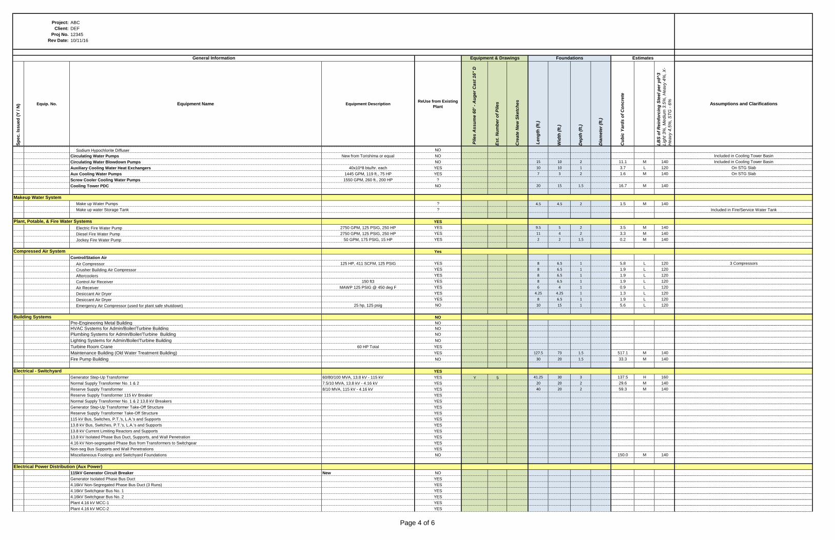
Sodium Hypochlorite Diffuser NO
Circulating Water Pumps New from Torishima or equal NO Included in Cooling Tower Basin
Circulating Water Blowdown Pumps NO 15 10 2 11.1 M 140 Included in Cooling Tower Basin
Auxiliary Cooling Water Heat Exchangers 40x10^8 btu/hr. each YES 10 10 1 3.7 L 120 On STG Slab
Aux Cooling Water Pumps 1445 GPM, 119 ft., 75 HP YES 7 3 2 1.6 M 140 On STG Slab
Screw Cooler Cooling Water Pumps 1550 GPM, 260 ft., 200 HP ?
Cooling Tower PDC NO 20 15 1.5 16.7 M 140
Make up Water Pumps ? 4.5 4.5 2 1.5 M 140
Make up water Storage Tank ? Included in Fire/Service Water Tank
YES
Electric Fire Water Pump 2750 GPM, 125 PSIG, 250 HP YES 9.5 5 2 3.5 M 140
Diesel Fire Water Pump 2750 GPM, 125 PSIG, 250 HP YES 11 4 2 3.3 M 140
Jockey Fire Water Pump 50 GPM, 175 PSIG, 15 HP YES 2 2 1.5 0.2 M 140
Yes
Control/Station Air
Air Compressor 125 HP, 411 SCFM, 125 PSIG YES 8 6.5 1 5.8 L 120 3 Compressors
Crusher Building Air Compressor YES 8 6.5 1 1.9 L 120
Aftercoolers YES 8 6.5 1 1.9 L 120
Control Air Receiver 150 ft3 YES 8 6.5 1 1.9 L 120
Air Receiver MAWP 125 PSIG @ 450 deg F YES 6 4 1 0.9 L 120
Desiccant Air Dryer YES 4.25 4.25 1 1.3 L 120
Desiccant Air Dryer YES 8 6.5 1 1.9 L 120
Emergency Air Compressor (used for plant safe shutdown) 25 hp, 125 psig NO 10 15 1 5.6 L 120
NO
Pre-Engineering Metal Building NO
HVAC Systems for Admin/Boiler/Turbine Building NO
Plumbing Systems for Admin/Boiler/Turbine Building NO
Lighting Systems for Admin/Boiler/Turbine Building NO
Turbine Room Crane 60 HP Total YES
Maintenance Building (Old Water Treatment Building) YES 127.5 73 1.5 517.1 M 140
Fire Pump Building NO 30 20 1.5 33.3 M 140
YES
Generator Step-Up Transformer 60/80/100 MVA, 13.8 kV - 115 kV YES Y 5 41.25 30 3 137.5 H 160
Normal Supply Transformer No. 1 & 2 7.5/10 MVA, 13.8 kV - 4.16 kV YES 20 20 2 29.6 M 140
Reserve Supply Transformer 8/10 MVA, 115 kV - 4.16 kV YES 40 20 2 59.3 M 140
Reserve Supply Transformer 115 kV Breaker YES
Normal Supply Transformer No. 1 & 2 13.8 kV Breakers YES
Generator Step-Up Transformer Take-Off Structure YES
Reserve Supply Transformer Take-Off Structure YES
115 kV Bus, Switches, P.T.'s, L.A.'s and Supports YES
13.8 kV Bus, Switches, P.T.'s, L.A.'s and Supports YES
13.8 kV Current Limiting Reactors and Supports YES
13.8 kV Isolated Phase Bus Duct, Supports, and Wall Penetration YES
4.16 kV Non-segregated Phase Bus from Transformers to Switchgear YES
Non-seg Bus Supports and Wall Penetrations YES
Miscellaneous Footings and Switchyard Foundations NO 150.0 M 140
115kV Generator Circuit Breaker New NO
Generator Isolated Phase Bus Duct YES
4.16kV Non-Segregated Phase Bus Duct (3 Runs) YES
4.16kV Switchgear Bus No. 1 YES
4.16kV Switchgear Bus No. 2 YES
Plant 4.16 kV MCC-1 YES
Plant 4.16 kV MCC-2 YES
Compressed Air System
Building Systems
Electrical - Switchyard
Electrical Power Distribution (Aux Power)
Makeup Water System
Plant, Potable, & Fire Water Systems
Page 4 of 6
Project: ABC
Client: DEF
Proj No. 12345
Rev Date: 10/11/16
Sp
ec
. Is
su
ed
(Y
/ N
) Equip. No. Equipment Name Equipment DescriptionReUse from Existing
Plant
Pile
s A
ss
um
e 6
0' -
Au
ge
r C
as
t 1
6" D
Es
t. N
um
be
r o
f P
ile
s
Cre
ate
Ne
w S
ke
tch
es
Le
ng
th (
ft.)
Wid
th (
ft.)
De
pth
(ft
.)
Dia
me
ter
(ft.
)
Cu
bic
Ya
rds
of
Co
nc
rete
LB
S o
f R
ein
forc
ing
Ste
el p
er
yd
^3
Lig
ht 3
%, M
ed
ium
3.5
%, H
ea
vy 4
%, X
-
He
avy 4
.5%
, S
TG
- 6
%
Assumptions and Clarifications
Equipment & Drawings Foundations Estimates
Fuel Handling
General Information
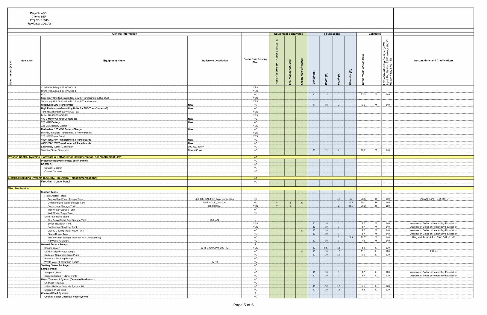
Crusher Building 4.16 kV MCC-3 YES
Crusher Building 4.16 kV MCC-4 YES
PDC NO 30 15 2 33.3 M 140
Secondary Unit Substation No. 1, with Transformers & Bus Duct YES
Secondary Unit Substation No. 2, with Transformers YES
Woodyard SUS Transformer New NO 8 10 2 5.9 M 140
High Resistance Grounding Units for SUS Transformers (5) New NO
Turbine/Generator 480 V MCC - 1A YES
Boiler 1B 480 V MCC-1C YES
480 V Motor Control Centers (8) New NO
125 VDC Battery New NO
125 VDC Battery Charger YES
Redundant 125 VDC Battery Charger New NO
Inverter, Isolation Transformer, & Power Panels YES
125 VDC Power Panel YES
480V-480/277V Transformers & Panelboards New NO
480V-208/120V Transformers & Panelboards New NO
Emergency Diesel Generator 100 kW, 480 V NO
Standby Diesel Generator New, 450 kW NO 25 12 2 22.2 M 140
NO
Protective Relay/Metering/Control Panels NO
DCS/PLC NO
Network Cabinet NO
Control Console NO
NO
Fire Alarm Control Panel NO
Storage Tanks
Field Erected Tanks
Service/Fire Water Storage Tank 450,000 GAL from Tank Connection NO 4.5 45 28.6 H 160 Ring wall Tank - O.D.=45'-0"
Demineralized Water Storage Tank NEW 4 X 40,000 GAL NO Y 3 S 2 20.5 35.2 H 160
Condensate Storage Tank 30,000 GAL YES Y 5 2 20.5 35.2 H 160
Well Water Storage Tank NO
Well Water Surge Tank NO
Shop Fabricated Tanks
Fire Pump Diesel Fuel Storage Tank 550 GAL ?
Boiler Blowdown Tank YES 10 10 1 3.7 M 140 Assume on Boiler or Heater Bay Foundation
Continuous Blowdown Tank YES 10 10 1 3.7 M 140 Assume on Boiler or Heater Bay Foundation
Closed Cooling Water Head Tank NO S 10 10 1 3.7 M 140 Assume on Boiler or Heater Bay Foundation
Steam Drains Tank NO 10 10 1 3.7 M 140 Assume on Boiler or Heater Bay Foundation
Waste Water Storage Tank (for Ash Conditioning) NO 7 23.5 22.7 M 140 Ring wall Tank - I.R.=10'-6", O.R.=11'-9"
Oil/Water Separator NO 20 10 1 7.4 M 140
General Service Pumps ?
Service Water 50 HP, 400 GPM, 108 PSI YES 10 5.67 1.5 3.2 L 120
Demineralized Water pumps NO S 10 10 1.5 11.1 L 120 2 Units
Oil/Water Separator Sump Pump NO 10 10 1.5 5.6 L 120
Blowdown Pit Sump Pumps NO
Waste Water Forwarding Pumps 30 Hp NO
Sanitary Sewer Package NO
Sample Panel ?
Sample Coolers NO 10 10 1 3.7 L 120 Assume on Boiler or Heater Bay Foundation
Instrumentation, Tubing, Vents NO 10 10 1 3.7 L 120 Assume on Boiler or Heater Bay Foundation
Water Treatment System (Demineralized water) NO
Cartridge Filters (2) NO
2 Pass Reverse Osmosis System Skid NO 10 10 1.5 5.6 L 120
Clean-In-Place Skid NO 10 10 1.5 5.6 L 120
Chemical Feed Systems ?
Cooling Tower Chemical Feed System NO
Process Control Systems (Hardware & Software; for instrumentation, see "Instrument List")
Electrical Building Systems (Security, Fire Alarm, Telecommunications)
Misc. Mechanical
Page 5 of 6
Project: ABC
Client: DEF
Proj No. 12345
Rev Date: 10/11/16
Sp
ec
. Is
su
ed
(Y
/ N
) Equip. No. Equipment Name Equipment DescriptionReUse from Existing
Plant
Pile
s A
ss
um
e 6
0' -
Au
ge
r C
as
t 1
6" D
Es
t. N
um
be
r o
f P
ile
s
Cre
ate
Ne
w S
ke
tch
es
Le
ng
th (
ft.)
Wid
th (
ft.)
De
pth
(ft
.)
Dia
me
ter
(ft.
)
Cu
bic
Ya
rds
of
Co
nc
rete
LB
S o
f R
ein
forc
ing
Ste
el p
er
yd
^3
Lig
ht 3
%, M
ed
ium
3.5
%, H
ea
vy 4
%, X
-
He
avy 4
.5%
, S
TG
- 6
%
Assumptions and Clarifications
Equipment & Drawings Foundations Estimates
Fuel Handling
General Information
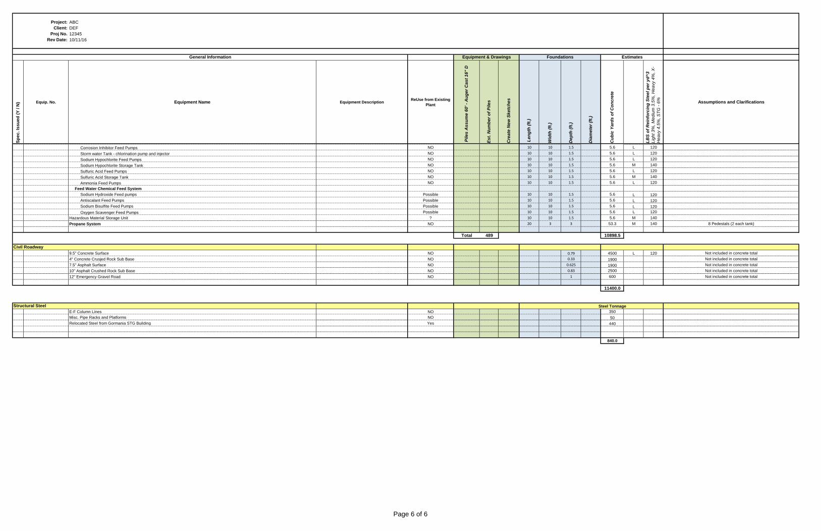
Corrosion Inhibitor Feed Pumps NO 10 10 1.5 5.6 L 120
Storm water Tank - chlorination pump and injector NO 10 10 1.5 5.6 L 120
Sodium Hypochlorite Feed Pumps NO 10 10 1.5 5.6 L 120
Sodium Hypochlorite Storage Tank NO 10 10 1.5 5.6 M 140
Sulfuric Acid Feed Pumps NO 10 10 1.5 5.6 L 120
Sulfuric Acid Storage Tank NO 10 10 1.5 5.6 M 140
Ammonia Feed Pumps NO 10 10 1.5 5.6 L 120
Feed Water Chemical Feed System
Sodium Hydroxide Feed pumps Possible 10 10 1.5 5.6 L 120
Antiscalant Feed Pumps Possible 10 10 1.5 5.6 L 120
Sodium Bisulfite Feed Pumps Possible 10 10 1.5 5.6 L 120
Oxygen Scavenger Feed Pumps Possible 10 10 1.5 5.6 L 120
Hazardous Material Storage Unit ? 10 10 1.5 5.6 M 140
Propane System NO 20 3 3 53.3 M 140 8 Pedestals (2 each tank)
Total 489 10898.5
9.5" Concrete Surface NO 0.79 4500 L 120 Not included in concrete total
4" Concrete Crusjed Rock Sub Base NO 0.33 1900 Not included in concrete total
7.5" Asphalt Surface NO 0.625 1900 Not included in concrete total
10" Asphalt Crushed Rock Sub Base NO 0.83 2500 Not included in concrete total
12" Emergency Gravel Road NO 1 600 Not included in concrete total
11400.0
Steel Tonnage
E-F Column Lines NO 350
Misc. Pipe Racks and Platforms NO 50
Relocated Steel from Gormania STG Building Yes 440
840.0
Civil Roadway
Structural Steel
Page 6 of 6