Embed Size (px)
Citation preview

Chapter 8
Anisotropic Propagation of Electromagnetic Waves
Gregory Mitchell
Additional information is available at the end of the chapter
http://dx.doi.org/10.5772/intechopen.75123
Provisional chapter
Anisotropic Propagation of Electromagnetic Waves
Gregory Mitchell
Additional information is available at the end of the chapter
Abstract
This chapter will analyze the properties of electromagnetic wave propagation in aniso-tropic media. Of particular interest are positive index, anisotropic, and magneto-dielectricmedia. Engineered anisotropic media provide unique electromagnetic properties includ-ing a higher effective refractive index, high permeability with relatively low magnetic losstangent at microwave frequencies, and lower density and weight than traditional media.This chapter presents research including plane wave solutions to propagation in aniso-tropic media, a mathematical derivation of birefringence in anisotropic media, modaldecomposition of rectangular waveguides filled with anisotropic media, and the fullderivation of anisotropic transverse resonance in a partially loaded waveguide. These arefundamental theories in the area of electromagnetic wave propagation that have beenreformulated for fully anisotropic magneto-dielectric media. The ensuing results will aideinterested parties in understanding wave behavior for anisotropic media to enhancedesigns for radio frequency devices based on anisotropic and magnetic media.
Keywords: anisotropic, wave propagation, dispersion, birefringence, waveguides,transverse resonance
1. Introduction
Recently engineered materials have come to play a dominant role in the design and implemen-tation of electromagnetic devices and especially antennas. Metamaterials, ferrites, andmagneto-dielectrics have all come to play a crucial role in advances made both in the function-ality and characterization of such devices. In fact, a movement towards utilizing customizedmaterial properties to replace the functionality of traditional radio frequency (RF) componentssuch as broadband matching circuitry, ground planes, and directive elements is apparent in theliterature and not just replacement of traditional substrates and superstrates with engineered
© 2016 The Author(s). Licensee InTech. This chapter is distributed under the terms of the Creative Commons
Attribution License (http://creativecommons.org/licenses/by/3.0), which permits unrestricted use,
distribution, and eproduction in any medium, provided the original work is properly cited.
DOI: 10.5772/intechopen.75123
© 2018 The Author(s). Licensee IntechOpen. This chapter is distributed under the terms of the CreativeCommons Attribution License (http://creativecommons.org/licenses/by/3.0), which permits unrestricted use,distribution, and reproduction in any medium, provided the original work is properly cited.

structures. A firm theoretical understanding of the electromagnetic properties of these mate-rials is necessary for both design and simulation of new and improved RF devices.
Inherently, many of these engineeredmaterials have anisotropic properties. Previously, the studyof anisotropy had been limited mostly to the realm of optical frequencies where the phenome-non occurs naturally in substances such as liquid crystals and plasmas. However, the recentdevelopment of the aforementioned engineered materials has encouraged the study of electro-magnetic anisotropy for applications at megahertz (MHz) and gigahertz (GHz) frequencies.
For the purposes of this chapter, an anisotropic electromagnetic medium defines permittivity(εr ) and permeability μr as separate tensors where the values differ in all three Cartesian
directions (εx6¼εy 6¼εz and μx6¼μy6¼μz). This is known as the biaxial definition of anisotropicmaterial which is more encompassing than the uniaxial definition which makes the simplify-ing assumption that εx = εy = εt and μx = μy = μt. The anisotropic definition also differs from thetraditional isotropic definition where εr and μr are the same in all three Cartesian directionsdefining each by a single value. For the definition of the tensor equations see Section 3.1.Anisotropic media yield characteristics such as conformal surfaces, focusing and refraction ofelectromagnetic waves as they propagate through a material, high impedance surfaces forartificial magnetic conductors as well as high index, low loss, and lightweight ferrite materials.The following sections aim to discuss in more detail some RF applications directly impacted bythe incorporation of anisotropic media and also give a firm understanding of electromagneticwave propagation as it applies to anisotropic media for different RF applications.
2. Applications of anisotropy in radio frequency devices
Traditionally, the study of anisotropic properties was limited to a narrow application spacewhere traditional ferrites, which exhibit natural anisotropy were the enabling technology. Thesetypes of applications included isolators, absorbers, circulators and phase shifters [1]. Traditionalferrites are generally very heavy and very lossy at microwave frequencies which are the twomain limiting factors narrowing their use in RF devices; however, propagation loss is an impor-tant asset to devices such as absorbers. Anisotropy itself leads to propagation of an RF signal indifferent directions, which is important in devices such as circulators and isolators [1]. For phaseshifters and other control devices the microwave signal is controlled by changing the bias fieldacross the ferrite [1, 2]. However, newer versions of some of these devices, utilizing FETs anddiodes in the case of phase shifters, rely on isotropic media to enable higher efficiency devices.
As early as 1958, Collin showed that at microwave frequencies, where the wavelength is larger,it is possible to fabricate artificial dielectric media having anisotropic properties [3]. This hasled some to investigate known theoretical solutions to typical RF problems, such as amicrostrip patch antenna, and extend them utilizing anisotropic wave propagation in dielectricmedia [4, 5]. The anisotropic dielectric antenna shows interesting features of basic antennaapplications featuring anisotropic substrates. While these solutions establish a framework forelectromagnetic wave propagation in anisotropic media, they simplify the problem by neces-sarily setting μr to 1 and only focusing on dielectric phenomena of anisotropy.
Antennas and Wave Propagation168

The concept of artificial media is also exemplified by the proliferation of metamaterialsresearch over the last few decades. Metamaterials incorporate the use of artificial microstruc-tures made of subwavelength inclusions that are usually implemented with periodic and/ormultilayered structures known as unit cells [6]. These devices operate where the wavelength ismuch larger than the characteristic dimensions of the unit cell elements. One characteristicfeature of some types of metamaterials is wave propagation anisotropy [7]. Anisotropicmetamaterials are used in applications such as directive lensing [8, 9], cloaking [10], electronicbeam steering [11], and metasurfaces [12] among others.
Finally, a class of engineered materials exists that exhibits positive refractive index, anisotropy,and magneto-dielectric properties with reduced propagation loss at microwave frequenciescompared to traditional ferrites. These materials show the unique ability to provide broadbandimpedance matches for very low profile antennas by exploiting the inherent anisotropy toredirect surface waves thus improving the impedance match of the antenna when very closeto a ground plane. Antenna profile on the orders of a twentieth and a fortieth of a wavelengthhave been demonstrated using these materials with over an octave of bandwidth and positiverealized gain [13, 14].
3. Plane wave solutions in an anisotropic medium
The recent development of low loss anisotropic magneto-dielectrics greatly expands the cur-rent antenna design space. Here we present a rigorous derivation of the wave equation anddispersion relationships for anisotropic magneto-dielectric media. All results agree with thosepresented by Meng et al. [15, 16]. Furthermore, setting μr = I , where I is the identity matrix,
yields results that agree with those presented by Pozar and Graham for anisotropic dielectricmedia [4, 5]. This section and the following section expand on the results presented by Menget al., Pozar and Graham. Incorporating a fully developed derivation of anisotropic propertiesof both εr and μr expands upon the simplification imposed by both Pozar and Graham that
uses an isotropic value of μr = 1. An expansion on the results of Meng et al. given in Section 4develops the waveguide theory including a full modal decomposition utilizing the biaxialdefinition of anisotropy versus their simplified uniaxial definition. The derivation of aniso-tropic cavity resonance in Section 4 differs from that of Meng et al. by addressing the separateissue of how the direct relationship of an arbitrary volume of anisotropic material will distortthe geometry of a cavity to maintain resonance at a given frequency. This property is especiallyimportant for the design of conformal cavity backed antennas for ground and air-based vehiclemobile vehicular platforms. Furthermore, the analysis of anisotropic properties is not restrictedto double negative (DNG) materials, which is the case for both of the Meng et al. studies.
3.1. Source free anisotropic wave equation
In order to solve for the propagation constants, we will need to formulate the dispersionrelationship from the anisotropic wave equation. This allows us to solve for the propagationconstant in the normal direction of the anisotropic medium. We start with the anisotropic, timeharmonic form of Maxwell’s source free equations for the electric and magnetic fields E and H
Anisotropic Propagation of Electromagnetic Waveshttp://dx.doi.org/10.5772/intechopen.75123
169

∇xE ¼ jωμoμr �H, (1)
∇xH ¼ �jωεoεr � E, (2)
where ω is the frequency in radians, εo is the permittivity of free space, μo is the permeability offree space, E = xoEx + yoEy + zoEz and H = xoHx + yoHy + zoHz. We define μr and εr as
εr ¼εx 0 00 εy 00 0 εz
264
375, (3)
μr ¼μx 0 00 μy 00 0 μz
264
375: (4)
Applying Eqs. (3) and (4) to Eqs. (1) and (2) yields the following
xodEZ
dy� dEY
dz
� �þ y
o
dEX
dz� dEZ
dx
� �þ zo
dEY
dx� dEX
dy
� �¼ �jωμo μxHXxo þ μyHYyo þ μzHZzo
� �,
(5)
xodHZ
dy� dHY
dz
� �þ y
o
dHX
dz� dHZ
dx
� �þ zo
dHY
dx� dHX
dy
� �¼ jωεo εxEXxo þ εyEYyo þ εzEZzo
� �:
(6)
Using the radiation condition, we assume a solution of E(x, y, z) = E(x, y)e�jkzz [17]. Now isolatethe individual components of (5) by taking the dot product with xo, yo, and zo respectively. Thisoperation yields the following equations
d=dyð ÞEz � jkzEy ¼ �jωμoμxHx, (7)
jkzEx � d=dxð ÞEz ¼ �jωμoμyHy, (8)
d=dxð ÞEy � d=dyð ÞEx ¼ �jωμoμzHz: (9)
Assuming a solution of H(x, y, z) = H(x, y)e�jkzz for (6), the same procedure yields [17]
d=dyð ÞHz � jkzHy ¼ jωεoεxEx, (10)
jkzHx � d=dxð ÞHz ¼ jωεoεyEy, (11)
d=dxð ÞHy � d=dyð ÞHx ¼ �jωμoμzHz: (12)
Using (7)–(12) allows for the transverse field components of the electric and magnetic fields interms of the derivatives of Hz and Ez as
Antennas and Wave Propagation170

Ex ¼ � jk2oμyεx � k2z
ωμoμy d=dyð ÞHz þ kz d=dxð ÞEz
� �, (13)
Ey ¼ jk2oμxεy � k2z
ωμoμx d=dxð ÞHz � kz d=dyð ÞEz� �
, (14)
Hx ¼ jk2oμxεy � k2z
ωεoεy d=dyð ÞEz � kz d=dxð ÞHz� �
, (15)
Hy ¼ � jk2oμyεx � k2z
ωεoεx d=dxð ÞEz þ kz d=dyð ÞHzð Þ: (16)
The relationships for the transverse field components, applied to (1) and (2), yield the follow-ing solutions for H and E, respectively
H ¼ � μr�1=jωεo
� �� ∇xEð Þ, (17)
E ¼ εr �1=jωεo� �
� ∇xHð Þ: (18)
Taking the cross product of both sides and substituting (1) and (2) for the right hand side of(17) and (18) yields
∇xεr �1 � ∇xHð Þ ¼ k2oμr �H, (19)
∇xμr�1 � ∇xEð Þ ¼ �k2oεr � E: (20)
Equations (19) and (20) represent the vector wave equations in an anisotropic medium [12].
3.2. Dispersion equation for Hz
We expand (19) in terms of (13)–(16)
∇x xoεx
d=dyð ÞHZ � d=dzð ÞHy� þ y
oεy
d=dzð ÞHx � d=dxð ÞHz½ �þ zoεz
d=dxð ÞHy � d=dyð ÞHx� o ¼ k2oμr �H,
(21)
Evaluating the remaining cross product of (21) yields the final form of the expanded waveequation
xoΠx þ yoΠy þ zoΠz ¼ k2oμr �H, (22)
Πx ¼ d2=dxdy� �
Hy � d2=dy2� �
Hx�
=εz � d2=dz2� �
Hx � d2=dxdz� �
Hz�
=εy, (23)
Πy ¼ d2=dydz� �
Hz � d2=dz2� �
Hy�
=εx � d2=dx2� �
Hy � d2=dxdy� �
Hx�
=εz, (24)
Πz ¼ d2=dxdz� �
Hx � d2=dx2� �
Hz�
=εy � d2=dy2� �
Hz � d2=dxdy� �
Hx�
=εx: (25)
Anisotropic Propagation of Electromagnetic Waveshttp://dx.doi.org/10.5772/intechopen.75123
171

Taking the dot product of (22) with zo allows the isolation of Hz on the right hand side of theequation in terms of (265 on the left hand side
d2=dydz� �
Hy � d2=dy2� �
Hz�
=εx � d2=dx2� �
Hz þ d2=dxdz� �
Hx�
=εy ¼ k2oμzHz, (26)
By keeping in mind that d/dz = �jkz, setting Ez = 0, and differentiating (15) and (16) by d2/dxdzand d2/dydz, produces the following result
k2zεy k2z � k2oεyμx
� �� 1εy
" #d2=dx2� �
Hz þ k2zεx k2z � k2oεxμy
� �� 1εx
24
35 d2=dy2� �
Hz ¼ k2oμzHz: (27)
Combining the d2Hz/dx2 and d2Hz/dy
2 terms in (27) gives the following second order differen-tial dispersion equation for Hz
k2oμx
k2oμxεy � k2zd2=dx2� �
Hz þk2oμy
k2oμyεx � k2zd2=dy2� �
Hz þ k2oμzHz ¼ 0: (28)
3.3. Dispersion equation for Ez
Expanding the ∇xE term of (18) in terms of (13)–(16) yields
∇x xo d=dyð ÞEZ � d=dzð ÞEY½ �=μx þ yo
d=dzð ÞEX � d=dxð ÞEZ½ �=μy
nþzo d=dxð ÞEY � d=dyð ÞEX½ �=μz
o¼ k2oεr � E:
(29)
Evaluating the remaining cross product of (29) gives the final form of the expanded waveequation
xoξx þ yoξy þ zoξz ¼ k2oεr � E, (30)
ξx ¼ d2=dxdy� �
EY � d2=dy2� �
Ex�
=μz � d2=dz2� �
Ex � d2=dxdz� �
Ez�
=μy, (31)
ξy ¼ d2=dydz� �
Ez � d2=dz2� �
Ey�
=μx � d2=dx2� �
Ey � d2=dxdy� �
Ex�
=μz, (32)
ξz ¼ d2=dxdz� �
Ex � d2=dx2� �
Ez�
=μy � d2=dy2� �
Ez � d2=dydz� �
Ey�
=μx: (33)
Taking the dot product of (30) with zo allows isolation of the Ez component on the right handside of the equation in terms of (33) on the left hand side
d2=dxdz� �
Ex � d2=dx2� �
Ez�
=μy þ d2=dydz� �
Ey � d2=dy2� �
Ez�
=μx ¼ k2oεzEz, (34)
Keeping in mind that d/dz = �jkz, setting Hz = 0, and differentiating (15) and (16) by d2/dxdz andd2/dydz produces the following result
Antennas and Wave Propagation172

k2zμy k2z � k2oμyεx
� �� 1μy
24
35 d2=dx2� �
Ez þ k2zμx k2z � k2oμxεy
� �� 1μx
" #d2=dy2� �
Ez ¼ k2oεzEz: (35)
Combining the d2Ez/dx2 and d2Ez/dy
2 terms in (35) gives the following second order differentialdispersion equation for Ez
k2oεxk2oμyεx � k2z
d2=dx2� �
Ez þk2oεy
k2oμxεy � k2zd2=dy2� �
Ez þ k2oεzEz ¼ 0: (36)
3.4. Transmission and reflection from an anisotropic half-space
Birefringence is a characteristic of anisotropic media where a single incident wave entering theboundary of an anisotropic medium gives rise to two refracted waves as shown in Figure 1 ora single incident wave leaving gives rise to two reflected waves as shown in Figure 2. We callthese two waves the ordinary wave and the extraordinary wave. To see how the anisotropy ofa medium gives rise to the birefringence phenomenon, Eqs. (28) and (36) will yield a solutionfor kz in the medium.
Equations (28) and (36) yield the following solutions in unbounded anisotropic mediarestricted by the radiation condition in all three dimensions
Ez x; y; zð Þ ¼ Eoe�j kxxþkyyþkzzð Þ, (37)
Hz x; y; zð Þ ¼ Hoe�j kxxþkyyþkzzð Þ: (38)
Figure 1. A plane wave incident from free space on an anisotropic boundary.
Anisotropic Propagation of Electromagnetic Waveshttp://dx.doi.org/10.5772/intechopen.75123
173
Plugging (37) into (36) (equivocally we could substitute (38) into (19)) allows the generation ofa polynomial equation whose solutions give the values of kz in the anisotropic medium. Notingthat d2=dx2 ¼ �k2x and d2=dy2 ¼ �k2y, (36) simplifies as
k2ok2xεxEz= k2oμyεx � k2z
� �þ k2oεyk
2yEz= k2oμxεy � k2z
� �� k2oεzEz ¼ 0: (39)
Dividing out the k2oEzterm and multiplying through by both denominators gives us the follow-ing factored polynomial
k2oμyεx � k2z� �
k2oμxεy � k2z� �
εz � k2xεx k2oμxεy � k2z� �� εyk2y k2oμyεx � k2z
� �¼ 0: (40)
Finally, multiplying out (40) yields a fourth order polynomial whose roots yield the four valuesof kz describing the ordinary wave and extraordinary wave in the positive and negativepropagation directions
k4zμz þ k2xμx þ k2yμy � εxμy þ εyμx
� �k2oμz
h ik2z þ k4oεxεyμxμyμz � k2okxεxμyμx � k2oεykyμxμy
h i¼ 0: (41)
Equation (41) is directly responsible for the existence of the extraordinary wave that is charac-teristic of the birefringence phenomenon. In an isotropic medium, the resulting polynomial for
Figure 2. A plane wave incident from an anisotropic medium on a free space boundary.
Antennas and Wave Propagation174

kz is a second order polynomial, which yields only the values for the positive and negativepropagation of the single ordinary wave.
4. Anisotropic rectangular waveguide
Electromagnetic wave behavior of waveguides is well understood in the literature. The modewithin a waveguide that are based on the voltage and current distributions within the wave-guide make up the basis for the electric and magnetic field calculations. This section derivessimilar formulations for a rectangular waveguide uniformly filled with an anisotropic mediumas shown in Figure 3. Figure 3 shows propagation in the zo-direction along the length of thewaveguide. Rectangular waveguides are most commonly used for material measurement andcharacterization, and therefore understanding how electromagnetic waves propagate in ananisotropic waveguide is important for material characterization purposes. Furthermore, thissection shows how the anisotropic derivation of waveguide behavior parallels that of a typicalwaveguide, and therefore how anisotropy may be applied to other waveguide geometries.
4.1. Anisotropic mode functions
Assume source free Maxwell’s equations in the same form as (1) and (2). Then the transverseelectromagnetic fields are defined
ETυ x; y; zð Þ ¼Xm
Xn
V 0υ zð Þe0υ x; yð ÞþV 00
υ zð Þe00υ x; yð Þ,�(42)
HTυ x; y; zð Þ ¼Xm
Xn
I0υ zð Þh0υ x; yð ÞþI00υ zð Þh00υ x; yð Þ,�(43)
Vυ zð Þ ¼ Voe�jkzz, (44)
Iυ zð Þ ¼ Ioe�jkzz, (45)
Figure 3. Cross section of a closed rectangular waveguide filled with anisotropic metamaterial and surrounded by PECwalls.
Anisotropic Propagation of Electromagnetic Waveshttp://dx.doi.org/10.5772/intechopen.75123
175

where ET and HT are the transverse electric and magnetic fields, V(z) and I(z) are the voltageand current at point z, e and h are the waveguide mode equations, and υ є [m, n] is the modenumber defined by the two indices m and n.
4.1.1. Incident TE mode
Assuming only a TE type mode in the waveguide sets Ez = 0. Then (13)–(16) become
E00xυ ¼ �jωμoμy d=dyð ÞH00
zυ= k2oμyεx � k2zυ� �
, (46)
E00yυ ¼ jωμoμx d=dxð ÞH00
zυ= k2oμxεy � k2zυ� �
, (47)
H00yυ ¼ �jk2zυ d=dxð ÞH00
zυ= k2oμxεy � k2zυ� �
, (48)
H00yυ ¼ �jk2zυ d=dyð ÞH00
zυ= k2oμyεx � k2zυ� �
: (49)
To solve for H00zυ we formulate the anisotropic wave equation from (1) and (2) where (52)
resembles (19)
∇� ∇�H ¼ jωεoεr � �jωμoμr �H� �
, (50)
∇� ∇�H ¼ jωεoεr � ∇� Eð Þ, (51)
∇� εr �1 � ∇�Hð Þ ¼ k2oμr �H: (52)
Expanding the curl of (52)
1εz
dχ00zυ
dy� 1εy
dχ00yυ
dz0 0
01εx
dχ00xυ
dz� 1εz
dχ00zυ
dx0
0 01εy
dχ00yυ
dx� 1εx
dχ00xυ
dy
2666666664
3777777775
1
1
1
26666664
37777775¼ k2o
μxH00xυ
μyH00yυ
μzH00zυ
266666664
377777775, (53)
χ00xυ ¼ d=dyð ÞH00
zυ � d=dzð ÞH00yυ, (54)
χ00yυ ¼ d=dzð ÞH00
xυ � d=dxð ÞH00zυ, (55)
χ00zυ ¼ d=dxð ÞH00
yυ � d=dyð ÞH00xυ: (56)
Isolating the zo-component of (53) gives the following relationship for H00zυ
d2=dxdz� �
H00xυ � d2=dx2
� �H00
zυ
� =εy þ d2=dydz
� �H00
yυ � d2=dy2� �
H00zυ
� �=εx � k2oμzH
00zυ ¼ 0, (57)
Antennas and Wave Propagation176

and substituting (48) and (49) for H00xυ and H
00yυ yields the following differential equation that
can be solved for H00zυ
k2oμx d2=dx2� �
H00zυ= k2oμxεy � k2zυ
� �þ k2oμy d2=dy2� �
H00zυ= k2oμyεx � k2zυ
� �þ k2oμzH
00zυ ¼ 0: (58)
Assuming a solution of the form
H00zυ ¼ Hocos kxυxð Þcos kyυy
� �e�jkzυz, (59)
kxυ ¼ mπ=a, (60)
kyυ ¼ nπ=b, (61)
which meets the boundary conditions at the PEC walls of the waveguide, then plugging (58)into (53) imposes the following restriction on the values of the tensors in (3) and (4)
μxk2xυ= k2oμxεy � k2zυ
� �þ μyk2yυ= k2oμyεx � k2zυ
� �¼ μz: (62)
Solving (62) for kzυ gives the following equation which yields four solutions to the propagationconstant for the ordinary and extraordinary waves described in Section 3.4
k2zυ ¼ k2o μxεy þ μyεx� �
� k2xυμx=μz � k2yυμy=μz
n
�ffiffiffiffiffiffiffiffiffiffiffiffiffiffiffiffiffiffiffiffiffiffiffiffiffiffiffiffiffiffiffiffiffiffiffiffiffiffiffiffiffiffiffiffiffiffiffiffiffiffiffiffiffiffiffiffiffiffiffiffiffiffiffiffiffiffiffiffiffiffiffiffiffiffiffiffiffiffiffiffiffiffiffiffiffiffiffiffiffiffiffiffiffiffiffiffiffiffiffiffiffiffiffiffiffiffiffiffiffiffiffiffiffiffiffiffiffiffiffiffiffiffiffiffiffi4k2xυk
2yυμxμy=μ
2z þ k2o μxεy � μyεx
� �� k2xυμx=μz þ k2yυμy=μz
h i2r ),2:
(63)
Equations (62) and (63) provide the criteria for determining the cutoff frequency for thepropagation of modes inside the waveguide. Plugging (59) into (46)–(49) yields the followingequations for the TE mode vectors in (42) and (43)
e 00υ x; yð Þ ¼ jωμoHo xoμykyυcos kxυxð Þsin kyυy� �
= k2oμyεx � k2zυ� �h
�yoμxkxυsin kxυxð Þcos kyυy
� �= k2oμxεy � k2zυ� �i
,(64)
h 00υ x; yð Þ ¼ jkzυHo xokxυsin kxυxð Þcos kyυy
� �= k2oμxεy � k2zυ� ��
þyokyυcos kxυxð Þsin kyυy
� �= k2oμyεx � k2zυ� �i
:(65)
4.1.2. Incident TM mode
Assuming only a TM type mode in the waveguide sets Hz = 0. Then (13)–(16) become
E0xυ ¼ �jkzυ d=dxð ÞE0
zυ= k2oμyεx � k2zυ� �
, (66)
E0yυ ¼ �jkzυ d=dyð ÞE0
zυ= k2oμxεy � k2zυ� �
, (67)
Anisotropic Propagation of Electromagnetic Waveshttp://dx.doi.org/10.5772/intechopen.75123
177

H0xυ ¼ jωεoεy d=dyð ÞE0
zυ= k2oμxεy � k2zυ� �
, (68)
H0yυ ¼ �jωεoεx d=dxð ÞE0
zυ= k2oμyεx � k2zυ� �
: (69)
Solving (66)–(69) for Ez and substituting (1) for ∇�H formulates the anisotropic wave equa-tion for E where (72) resembles (20)
∇� ∇� E ¼ �jωμoμr � ∇�Hð Þ, (70)
∇� ∇� E ¼ �jωμoμr � jωεoεr � E� �
, (71)
∇� μr�1 � ∇� Eð Þ ¼ k2oεr � E: (72)
Equation (72) represents the anisotropic wave equation for the time harmonic electric field.Expanding the curl of (72) and isolating the zo component as we did for Hz in Section 4.1.1yields the following solution for the Ez component
E0zυ ¼ Eosin kxυxð Þsin kyυy
� �e�jkzυz: (73)
Plugging (73) into (66)–(69) yields the following equations for the TM mode vectors in (42) and(43)
e0υ x; yð Þ ¼ �jkzυEo xokxυcos kxυxð Þsin kyυy
� �= k2oμyεx � k2zυ� �
þyosin kxυxð Þcos kyυy
� �= k2oμyεx � k2zυ� �i
,h
(74)
h0υ x; yð Þ ¼ jωεoEo xoεykyυsin kxυxð Þcos kyυy
� �= k2oμxεy � k2zυ� �� y
oεxkxυcos kxυxð Þsin kyυy
� �=k2oμyεx � k2zυ
i:
h(75)
4.2. Anisotropic transverse resonance
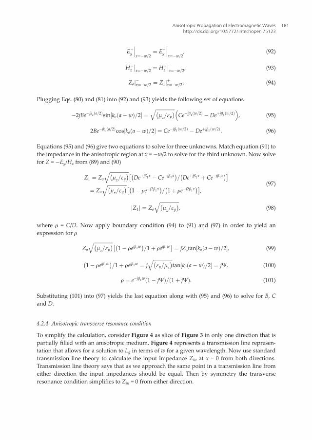
This section describes the derivation of an anisotropic transverse resonance conditionestablished between resonant walls of a rectangular waveguide. Assume an infinite rectangu-lar waveguide partially loaded with an anisotropic medium, then w(z) represents the width ofthe anisotropic medium at any point z along the direction of propagation as shown in Figure 4.
Figure 4. Symmetrically loaded transmission line model with a short at either end.
Antennas and Wave Propagation178
At any length z along the waveguide, the assumption that the horizontal distance between tworesonant walls represented as a partially filled parallel plate waveguide is a valid presumption.We can calculate Lg(z) as the unknown distance between the edge of the anisotropic mediumand the cavity wall based on a transverse resonance condition in the xo-direction. However, wefirst need to derive the characteristic impedance of the anisotropic region in the transmissionline model.
4.2.1. Electromagnetic fields in free space regions
Calculating the fields in the free space region of the waveguide begins with Maxwell’s sourcefree Eqs. (1) and (2) and the equations for the individual vector components of the electromag-netic fields (13)–(16). Using the standard derivation of the wave equation for Hz in free spacefrom (1) and (2) shows
∇T � ∇T �Hυ ¼ jωεo ∇T � Eυ
� � ¼ ∇T ∇T �Hυð Þ � ∇2THzυ, (76)
jωεo �jωμoHzυ� �þ ∇2
THzυ ¼ 0, (77)
d2=dx2� �þ d2=dy2
� �þ k2o�
Hzυ ¼ 0: (78)
Utilizing (52) and setting kzo = 0 due to the assumption of the transverse resonance condi-tion in the free space region of the waveguide will lead to the solution to Hz. Assuming thedominate mode to be TE10 because a ≥ 2b, then kyo = 0 for the first resonance at cutoff [1].With kyo = 0 no variation of the fields in the yo direction and (d2/dy2)Hz = 0 then (78)becomes
d2=dx2 þ k2o� �
Hz ¼ 0: (79)
Equation (80) is a standard differential equation with a known solution [17]
Hzυ ¼ Ae�jkox þ Beþjkox, (80)
where A and B are yet to be determined coefficients. Substituting (80) into (13)–(16) yields theexpression for Ey
Ey ¼ koωμo Ae�jkox � Beþjkox� �
=k2o ¼ Zo Ae�jkox � Beþjkox� �
: (81)
Accounting for the restrictions imposed by the transverse resonance conditions on Ez, kzo andkyo, then Ex = 0, Hx = 0 and Hy = 0 as well.
4.2.2. Electromagnetic fields in anisotropic region
Starting with (1) and (2) for the source free Maxwell’s equations in an anisotropic medium, thevector components (13)–(16) led to the derivation of the dispersion Eqs. (26) and (38) forHz andEz, respectively.
Anisotropic Propagation of Electromagnetic Waveshttp://dx.doi.org/10.5772/intechopen.75123
179

The cutoff frequency or resonance of a rectangular waveguide is determined when the propa-gation constant in the direction of resonance, in the case the xo-direction, is 0 [1]. By definition,when the waveguide’s dominant mode υ = 1 propagates, then kx1 > 0 and the guide is resonantwhereas when the mode attenuates then kx1 < 0 and there is no resonance. Therefore, theresonance first manifests itself when kx1 = 0. For the dominate mode to be TE10 then a ≥ 2b andd2Hz/dy
2 = 0. Simplifying (28) with these substitutions produces a simpler form to solve for Hz
d2=dx2� �þ k2oμzεy�
Hz ¼ 0, (82)
β ¼ koffiffiffiffiffiffiffiffiffiμzεy
p: (83)
Solving (82) for Hz and plugging the result into (13)–(16) yields
Hz ¼ Ce�jβx þDeþjβx, (84)
Ey ¼ Zoβ Ce�jβx �Deþjβx� �=koεy ¼ Zo
ffiffiffiffiffiffiffiffiffiffiffiffiμz=εy
qCe�jβx �Deþjβx� �
, (85)
We can see from (13)–(16) that based on our resonance conditions on Ez, kz1 and ky1 that Ex = 0,Hx = 0 and Hy = 0.
4.2.3. Characteristic impedances of the two regions
The first boundary condition exists at the perfect electric conductor (PEC) boundary whenx = �a/2 and E(x, y, z) = 0
Ey��x¼�a=2 ¼ 0 ! Aejkoa=2 ¼ Be�jkoa=2, (86)
A ¼ Be�jkoa: (87)
Plugging (87) into (80) and (81) yields
Ey ¼ ZoBe�jkoa=2 e�jko xþa=2ð Þ � eþjko xþa=2ð Þh i
, (88)
Ey ¼ �2ZoBe�jkoa=2sin ko xþ a=2ð Þ½ �: (89)
Similarly,
Hz ¼ 2Be�jkoa=2cos ko xþ a=2ð Þ½ �: (90)
Equations (89) and (90) solve for the impedance of the free space region as Z = �Ey/Hz
Zo ¼ �Ey=Hz ¼ jZotan ko xþ a=2ð Þ½ �, (91)
within the region 0 ≤ (x + a/2) ≤ (a�w)/2. The second boundary condition exists at x = �w/2where the tangential fields at the boundary are equal. In this case, there are two tangentialfields in Ey and Hz. At the boundary, we have the following three conditions
Antennas and Wave Propagation180
E�y
���x¼�w=2
¼ Eþy
���x¼�w=2
, (92)
H�z
��x¼�w=2 ¼ Hþ
z
��x¼�w=2, (93)
Zoj�x¼�w=2 ¼ Z1jþx¼�w=2: (94)
Plugging Eqs. (80) and (81) into (92) and (93) yields the following set of equations
�2jBe�jko a=2ð Þsin ko a� wð Þ=2½ � ¼ffiffiffiffiffiffiffiffiffiffiffiffiffiffiffiffiμz=εy� �q
Ce�jβ1 w=2ð Þ �Deþjβ1 w=2ð Þ� �
, (95)
2Be�jko a=2ð Þcos ko a� wð Þ=2½ � ¼ Ce�jβ1 w=2ð Þ �Deþjβ1 w=2ð Þ: (96)
Equations (95) and (96) give two equations to solve for three unknowns. Match equation (91) tothe impedance in the anisotropic region at x = �w/2 to solve for the third unknown. Now solvefor Z = �Ey/Hz from (89) and (90)
Z1 ¼ Zo
ffiffiffiffiffiffiffiffiffiffiffiffiffiffiffiffiμz=εy� �q
Deþjβ1x � Ce�jβ1x� �
= Deþjβ1x þ Ce�jβ1x� ��
¼ Zo
ffiffiffiffiffiffiffiffiffiffiffiffiffiffiffiffiμz=εy� �q
1� re�j2β1x� �
= 1þ re�j2β1x� ��
,(97)
Z1j j ¼ Zo
ffiffiffiffiffiffiffiffiffiffiffiffiffiffiffiffiμz=εy� �q
, (98)
where r = C/D. Now apply boundary condition (94) to (91) and (97) in order to yield anexpression for r
Zo
ffiffiffiffiffiffiffiffiffiffiffiffiffiffiffiffiμz=εy� �q
1� rejβ1w� �
=1þ rejβ1w� ¼ jZotan ko a� wð Þ=2½ �, (99)
1� rejβ1w� �
=1þ rejβ1w ¼ jffiffiffiffiffiffiffiffiffiffiffiffiffiffiffiffiεy=μz
� �qtan ko a� wð Þ=2½ � ¼ jΨ, (100)
r ¼ e�jβ1w 1� jΨð Þ= 1þ jΨð Þ: (101)
Substituting (101) into (97) yields the last equation along with (95) and (96) to solve for B, Cand D.
4.2.4. Anisotropic transverse resonance condition
To simplify the calculation, consider Figure 4 as slice of Figure 3 in only one direction that ispartially filled with an anisotropic medium. Figure 4 represents a transmission line represen-tation that allows for a solution to Lg in terms of w for a given wavelength. Now use standardtransmission line theory to calculate the input impedance Zin at x = 0 from both directions.Transmission line theory says that as we approach the same point in a transmission line fromeither direction the input impedances should be equal. Then by symmetry the transverseresonance condition simplifies to Zin = 0 from either direction.
Anisotropic Propagation of Electromagnetic Waveshttp://dx.doi.org/10.5772/intechopen.75123
181

Starting with the short located at x = a/2, calculate Zin2 at x = w/2 as
Zin2 ¼ jZotan koLg� �
: (102)
Now calculate Zin1 at x = 0 as
Zin1 ¼ Z1 Zin2 þ jZ1tan β1w=2� ��
= Z1 þ jZin2tan β1w=2� ��
: (103)
The symmetric transverse resonance condition simplifies (103) to
Z1 þ jZin2tan β1w=2� � ¼ 0: (104)
Plugging (98) and (101) into (104) yields the following equation for Lg [14]
Lg ¼ λtan�1ffiffiffiffiffiffiffiffiffiffiffiffiffiffiffiffiμz=εy� �q
=tan πwffiffiffiffiffiffiffiffiffiμzεy
p=λ
� � �= 2πð Þ: (105)
where λ is wavelength. Importantly, the solution of (105) shows that the transverse resonanceonly depends on two of the six εr and μr components. This means that maintaining a constant
resonance in a waveguide or cavity relies on the clever engineering of εy and μz and leavesdesigners free to adjust the other components as they see fit to enhance performance in otherways. Furthermore, if εy = μz = 1 then the resonance in the xo direction will see the anisotropicsubstrate as air, while other tensor elements can be utilized to achieve performance attributedto materials with an arbitrarily high refractive index.
4.2.5. Suppression of birefringence in a rectangular waveguide
Section 3.4 discusses the phenomenon of birefringence in an unbounded anisotropic half-spaceby deriving the existence of a fourth order polynomial for the wavenumber in the propagationdirection. However, for low order resonances, a rectangular waveguide suppresses the bire-fringence inherent to anisotropic media by suppressing propagation in the vertical direction ofthe waveguide. In other words, ky = 0 and d2/dy2 = 0 assuming the horizontal dimension of thewaveguide is at least twice the size of the vertical dimension or a ≥ 2b in Figure 1 [3]. Thebound on the waveguide geometry simplifies (39), the dispersion equation for Ez in an aniso-tropic waveguide, to
k2ok2xεxEz= k2oμyεx � k2z
� �� k2oεzEz ¼ 0, (106)
and results in the following second order polynomial for kz
k2z ¼ εx k2oμy � k2x=εz� �
: (107)
The suppression of the ky term in (39) yields a second order differential equation for the wavenumber in the propagation direction, thereby eliminating the property of birefringence for thiscase.
Antennas and Wave Propagation182
5. Conclusions
Recently engineered materials have come to play an important role in state of the art designselectromagnetic devices and especially antennas. Many of these engineered materials haveinherent anisotropic properties. Anisotropic media yield characteristics such as conformalsurfaces, focusing and refraction of electromagnetic waves as they propagate through a mate-rial, high impedance surfaces for artificial magnetic conductors as well as high index, low loss,and lightweight ferrite materials. This chapter analyzes the properties of electromagnetic wavepropagation in anisotropic media, and presents research including plane wave solutions topropagation in anisotropic media, a mathematical derivation of birefringence in anisotropicmedia, modal decomposition of rectangular waveguides filled with anisotropic media, and thefull derivation of anisotropic transverse resonance in a partially loaded waveguide.
Author details
Gregory Mitchell
Address all correspondence to: [email protected]
U.S. Army Research Laboratory, Adelphi, USA
References
[1] Pozar DM. Microwave Engineering. 3rd ed. New York: John Wiley and Sons; 2005. pp.106-117
[2] Ince WJ, Stern E. Mint: Non-reciprocal remanence phase shifters in rectangular wave-guide. IEEE Transactions on Microwave Theory and Techniques. 1967;MTT-15(2):87-95
[3] Collin R. Mint: A simple artificial anisotropic medium. IRE Transactions on MicrowaveTheory and Techniques. 1958;6:206-209
[4] Pozar D. Mint: Radiation and scattering from a microstrip patch on a uniaxial substrate.IEEE Transactions on Antennas and Propagation. 1987;AP-35(6):613-621
[5] Graham J. Arbitrarily Oriented Biaxlly Anisotropic Media: Wave Behvaior and MicrostripAntennas [thesis]. Syracuse: University of Syracuse; 2012
[6] Torrent D, Sanchez-Dehesa J. Radial wave crystals: Radially periodic structures fromanisotropic metamaterials for engineering acoustic or electromagnetic waves. PhysicsReview Letters. 2009;103
[7] Sanchez-Dehesa J, Torrent D, Carbonell J. Anisotropic metamaterials as sensing devices inacoustics and electromagnetism. In: The Proceedings of the International Society forOptics and Photonics (SPIE). 2012; San Diego, California. Washington: SPIE
Anisotropic Propagation of Electromagnetic Waveshttp://dx.doi.org/10.5772/intechopen.75123
183
[8] Ma YG, Wang P, Chen X, Ong CK. Mint: Near-field plane-wave-like beam emittingantenna fabricated by anisotropic metamaterial. Applied Physics Letters. 2009;94
[9] Cheng Q. Directive radiation of electromagnetic waves based on anisotropic metamaterials.In: The Proceedings of IEEE Asia-Pacific Conference on Antennas and Propagation. Singa-pore. New York: IEEE; 27–29 August 2012
[10] Schurig D, Mock JJ, Justice BJ, Cummer SA, Pendry JB, Starr AF, Smith DR. Metamaterialelectromagnetic cloak at microwave frequencies. Science. 2006;314:977-980
[11] Wong J, Balmain K. A beam-steerable antenna based on the spatial filtering property ofhyperbolically anisotropic metamaterials. In: The Proceedings of IEEE International Sym-posium of the Antennas and Propagation Society. Honolulu. New York: IEEE; 9–15 June2007
[12] Cai T, Wang GM. Polarization-controlled bifunctional antenna based on 2-D anisotropicgradient metasurface. In: The Proceedings of IEEE Conference on Microwave and Milli-meter Wave Technology. Beijing. New York: IEEE; 5–8 June 2016
[13] Mitchell G, Weiss S. An overview of ARL's low profile antenna work utilizing anisotropicmetaferrites. In: The Proceedings of the IEEE International Symposium on Phased ArraySystems and Technology. Waltham. New York: IEEE; 18–21 October 2016
[14] Mitchell G, Wasylkiwskyj W. Mint: Theoretical anisotropic resonance technique for thedesign of low-profile wideband antennas. IET Microwaves, Antennas & Propagation.2016;10:487-493
[15] Meng FY, Wu Q, Li LW. Mint: Transmission characteristics of wave modes in a rectangu-lar waveguide filled with anisotropic Metamaterial. Applied Physics A: Materials Scienceand Processing. 2009;94:747-753
[16] Meng FY, Wu Q, Fu JH. Mint: Miniaturized rectangular cavity resonator based on aniso-tropic metamaterials bilayer. Microwave and Optical Technology Letters. 2008;50:2016-2020
[17] BoyceWE, DiPrima RC. Elementary Differential Equations. 7th ed. New York: JohnWileyand Sons; 2001
Antennas and Wave Propagation184