Embed Size (px)
Citation preview

CHAPTER EIGHTEEN
Optics of Anisotropic Media
18
Optics of Anisotropic Media
18.1 Introduction
In this chapter we discuss wave propagation in anisotropic media. We
shall see that in such media the electric vector of a propagating wave
is not in general parallel to its polarization direction – defined by the
direction of its electric displacement vector. Further, for propagation of
plane waves in a particular direction through an anisotropic medium two
distinct possible polarization directions exist, and waves having these
polarization directions propagate with different velocities. We shall dis-
cuss an ellipsoidal surface called the indicatrix and show how with its
aid the allowed polarization directions and their corresponding refrac-
tive indices can be determined for wave propagation in a given direction.
Other three-dimensional surfaces related to the indicatrix and their use
in describing different optical properties of anisotropic media are also
discussed. We shall concentrate our attention primarily on uniaxial crys-
tals, which have optical properties that can be referred to an indicatrix
with two equal axes, and will discuss how such crystals can be used to
control the polarization characteristics of light.
Important anisotropic optical media are generally crystalline and their
optical properties are closely related to various symmetry properties
possessed by crystals. To assist the reader who is not familiar with
basic ideas of crystal symmetry, Appendix 5 summarizes a number of
aspects of this subject that should be helpful in reading this chapter and
a number of those succeeding it.
586 Optics of Anisotropic Media
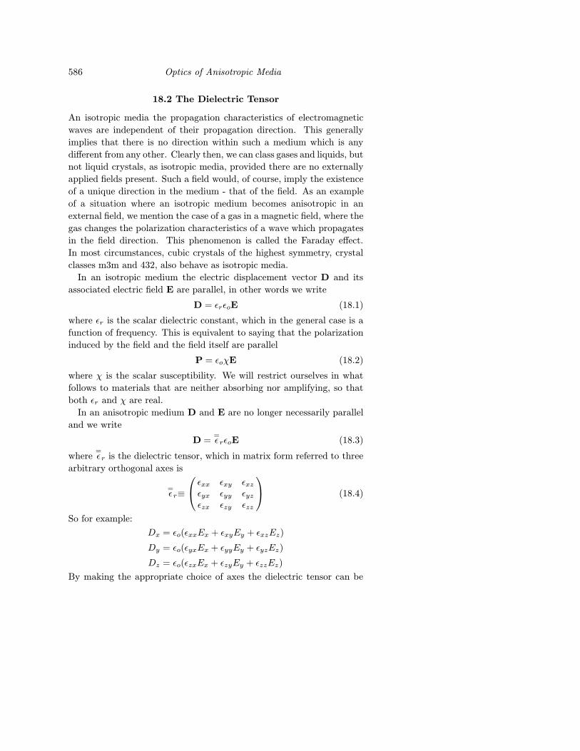
18.2 The Dielectric Tensor
An isotropic media the propagation characteristics of electromagnetic
waves are independent of their propagation direction. This generally
implies that there is no direction within such a medium which is any
different from any other. Clearly then, we can class gases and liquids, but
not liquid crystals, as isotropic media, provided there are no externally
applied fields present. Such a field would, of course, imply the existence
of a unique direction in the medium - that of the field. As an example
of a situation where an isotropic medium becomes anisotropic in an
external field, we mention the case of a gas in a magnetic field, where the
gas changes the polarization characteristics of a wave which propagates
in the field direction. This phenomenon is called the Faraday effect.
In most circumstances, cubic crystals of the highest symmetry, crystal
classes m3m and 432, also behave as isotropic media.
In an isotropic medium the electric displacement vector D and its
associated electric field E are parallel, in other words we write
D = εrεoE (18.1)
where εr is the scalar dielectric constant, which in the general case is a
function of frequency. This is equivalent to saying that the polarization
induced by the field and the field itself are parallel
P = εoχE (18.2)
where χ is the scalar susceptibility. We will restrict ourselves in what
follows to materials that are neither absorbing nor amplifying, so that
both εr and χ are real.
In an anisotropic medium D and E are no longer necessarily parallel
and we write
D ==εrεoE (18.3)
where=εr is the dielectric tensor, which in matrix form referred to three
arbitrary orthogonal axes is
=εr≡
εxx εxy εxzεyx εyy εyzεzx εzy εzz
(18.4)
So for example:
Dx = εo(εxxEx + εxyEy + εxzEz)
Dy = εo(εyxEx + εyyEy + εyzEz)
Dz = εo(εzxEx + εzyEy + εzzEz)
By making the appropriate choice of axes the dielectric tensor can be
The Dielectric Tensor 587
diagonalized. With this choice of axes, called the principal axes of the
material, Eq. (18.5) in matrix form becomesDx
Dy
Dz
= εo
εx 0 00 εy 00 0 εz
ExEyEz
(18.6)
where εx, εy and εz are called the principal dielectric constants.
Alternatively, we can describe the anisotropic character of the medium
with the aid of the susceptibility tensor=χ
P = εo=χ E (18.7)
where=χ has the matrix form when referred to three arbitrary orthogonal
axes
=χ≡
χxx χxy χxzχyx χyy χyzχzx χzy χzz
(18.8)
and in the principal coordinate system
=χ≡
χx 0 00 χy 00 0 χz
(18.9)
Since D = εoE + P, it is clear that in a principal coordinate system
εx = 1 + χx, etc. (18.10)
We can understand why crystals with less than cubic symmetry have
susceptibilities which depend on the direction of the applied field by
considering the physical relationship between polarization and applied
field. When a field E is applied to a crystal, it displaces both electrons
and nuclei from their equilibrium positions in the lattice and induces a
net dipole movement per unit volume (polarization), which we can write
in the form:
P =∑j
Njej∆rj (18.11)
where Nj is the density of species j with charge ej in the crystal and ∆rjis the displacement of this charged species from its equilibrium position.
We should note that when the applied field is at optical frequencies, only
electrons make any significant contribution to this polarization, partic-
ularly the most loosely bound outer valence electrons of the ions within
the lattice. The ions themselves are too heavy to follow the rapidly oscil-
lating applied field. If the applied electric field has components Ex, Eyand Ez , then in equilibrium we can write
Ex = −kjx(∆rj)x (18.12)
588 Optics of Anisotropic Media
and two other similar equations, where kjx is a restoring force constant
appropriate to the x component of the displacement of the charge j from
its equilibrium position; thus
∆rj = (Ex
kjxı+
Ey
kjy+
Ez
kjzk) (18.13)
which is a vector parallel to E only if all three force constants are equal.
The equality of these force constants for displacement along three or-
thogonal axes would imply an arrangement with cubic symmetry of the
ions in the lattice about the charged particle being considered.
18.3 Stored Electromagnetic Energy in Anisotropic Media
If we wish the stored energy density in an electromagnetic field to be
the same in an anisotropic medium as it is in an isotropic one then we
require
U =1
2(E·D + B·H) (18.14)
which gives
U =1
2(=εr ε0E·E + B·H) (18.15)
Now, in any medium the net power flow into unit volume is *
∂U
∂t= −∇·(E×H) = E·∂D
∂t+ H
∂B
∂t
= εoE·=εr
∂E
∂t+ H·∂B
∂t
(18.16)
where we have assumed that the medium is non-conductive so that j = 0.
Eq. (18.16) gives the rate of change of stored energy within unit volume,
which must also be given by the time derivative of Eq. (18.15)
∂U
∂t=
1
2(εo
=εr
∂
∂t(E·E) +
∂
∂t(B·H)) (18.17)
Most optical crystals are not, or are only very slightly, magnetic so we
can assume that B = µoH since µr ' 1. In this case
1
2
∂
∂tB·H = H·∂B
∂t(18.18)
so comparing the first term on the R.H.S. of Eq. (18.16) with the first
two terms on the R.H.S. of (18.17)
εoE·=εr
∂E
∂t=
1
2(εo
=εr E·∂E
∂t+ εo
=εr
∂E
∂t·E) (18.19)
* See Appendix xxx.
Propagation of Monochromatic Plane 589
which implies that
=εr E·∂E
∂t=
=εr
∂E
∂t·E. (18.20)
Written out in full Eq. (18.20) is
εxxExEx + εxyEyEx + εxzEzEx + εyxExEy + εyyEyEy
+εyzEzEy + εzxExEz + εzyEyEz + εzzEzEz
= εxxExEx +ExyEyEx + εxzEzEx + εyxExEy
+εyyEyEy + εyzEzEy + εzxExEz + εzyEyEz + εzzEzEz (18.20a)
Clearly εxy = εyx; εxz = εzx; etc. so the dielectric tensor only has
6 independent terms. By working in the principal coordinate system,
all the off-diagonal terms of the dielectric tensor become zero, which
greatly simplifies consideration of the wave propagation characteristis of
anisotropic crystals. In this case we can write
Dx = εoεxEx; Dy = εoεyEy; Dz = εoεzEz (18.21)
where we are writing εx = εxx, etc., for simplicity and the electrical
energy density in the crystal becomes
UE =1
2E·D =
1
2ε0(D2x
εx+D2y
εy+D2z
εz) (18.22)
which shows that the electric displacement vectors from a given point
that correspond to a constant stored electrical energy describe an ellip-
soid.
18.4 Propagation of Monochromatic Plane
Waves in Anisotropic Media
Let us assume that a monochromatic plane wave of the form
D = Do exp[i(ωt− k·r)] = Doeiφ
can propagate through an anisotropic medium. The direction of D spec-
ifies the direction of polarization of this wave. The wave vector k of this
plane wave is normal to the wavefront (the plane where the phase of the
wave is everywhere equal) and has magnitude | k |= ω/c; c is the phase
velocity of the wave, which is related to the velocity of light in vacuo, co,
by the refractive index n experienced by the wave according to c = co/n.
The phase velocity of the wave in a particular wave vector direction in
the crystal can also be written as c = ω/|k|.
590 Optics of Anisotropic Media
We assume that Maxwell’s equations still hold, so that in the absence
of currents or free charges
div D = 0 (18.23)
div B = 0 (18.24)
curl E =−∂B
∂t(18.25)
curl H =∂D
∂t(18.26)
We stress that because D and E are now related by a tensor operation,
div E is no longer zero.
Taking the curl of both sides of Eq. (18.25)
curl curlE = − ∂
∂t( curl µoH) = −µo
∂
∂t(∂D
∂t) = −µo
∂2
∂t2(εo
=εr E)
(18.27)
and using the vector identity curl curl E = grad (div E)−∇2E gives
∇2E− grad (divE) = εoµo=εr
∂2E
∂t2(18.28)
In the principal coordinate system the x component of Eq. (18.28) is,
for example
∂2Ex
∂x2+∂2Ex
∂y2+∂2Ex
∂z2− ∂
∂x(∂Ex
∂x+∂Ey
∂y+∂Ez
∂z) = εoµoεx
∂2Ex
∂t2(18.29)
For a plane wave of the form above, again in the principal coordinate
system,
ε0εxEx = Dx = (Do)x exp[i(wt− (kxx+ kyy + kzz))] (18.30)
where kx, ky and kz are the three orthogonal components of the wave
vector and εx depends on the angular frequency ω; with similar equations
for Ey and Ez . Substituting for Ex = Dx/εoεx in Eq. (18.29) gives
Dx
εx(k2x + k2
y + k2z)− kx(
kxDx
εx+kyDy
εy+kzDz
εz) = εoµoω
2Dx (18.31)
and two other similar equations. Recognizing that
εoµo =1
c2o(18.32)
and
(k2x + k2
y + k2z) = | k |2, (18.33)
and writing
εoc2o
| k |2 (kxEx + kyEy + kzEz) = P 2 (18.34)
The Two Possible Directions of D 591
Eq. (18.31) becomes
Dx =−kxP 2
c2 − c2x(18.35)
and similarly
Dy =−kyP 2
c2 − c2y(18.36)
Dz =−kzP 2
c2 − c2z(18.37)
where cx = co/ε1/2x ; cy = co/ε
1/2y and cz = co/ε
1/2z are called the principal
phase velocities of the crystal. Now, since div D = −i(kxDx + kyDy +
kzDz) = 0, we have
k2x
c2 − c2x+
k2y
c2 − c2y+
k2z
c2 − c2z= 0. (18.38)
Multiplying both sides of Eq. (18.38) by c2 and rearranging gives
k2xn
2x
n2 − n2x
+k2yn
2y
n2 − n2y
+k2zn
2z
n2 − n2z
= 0, (18.39)
where we have put nx = ε1/2x , ny = ε
1/2y , and nz = ε
1/2z ; nx, ny and nz
are called the principal refractive indices of the crystal. Eq. (18.38) and
Eq. (18.39), which is called Fresnel’s equation, are quadratic in c2 and
n2 respectively. Thus in general there are two possible solutions c1, c2and n1, n2, respectively, for the phase velocity and refractive index of a
monochromatic wave propagating through an anisotropic medium with
wave vector k. However, when k lies in certain specific directions both
roots of Eqs. (18.38) and (18.39) become equal. These special directions
within the crystal are called optic axes. The fact that, for example,
(n21)1/2 has two roots +n1 and −n1 merely corresponds to each solution
of Eq. (18.39) allowing a wave to propagate in a given direction either
with wave vector k or −k.
18.5 The Two Possible Directions of D for
a Given Wave Vector are Orthogonal
We can show that the two solutions of Eq. (18.38) and (18.39) correspond
to two different possible linear polarizations of a wave propagating with
wave vector k and that these two solutions have mutually othogonal
polarization. Let us first illustrate this by considering some special cases.
If we send a monochromatic wave into an anisotropic crystal travelling
592 Optics of Anisotropic Media
in the z direction, but linearly polarized in the x direction, then from
Maxwell’s Eqs. (18.25) and (18.26)
∂Ex
∂z= −µrµo
∂Hy
∂t(18.40)
∂Hy
∂z= −εxεo
∂Ex
∂t(18.41)
where we have taken the axes x, y, and z to correspond to the principal
coordinate system of the crystal. Taking the z derivative of Eq. (18.40)
and substituting for ∂Hy/∂z from (18.41) gives
∂2Ex
∂z2= µrµoεxεo
∂2Ex
∂t2(18.42)
which is a one-dimensional wave equation with a solution of the form
Ex = (Eo)xei(ωt−kxz) (18.43)
where kx = ω(µrµoεxεo)1/2
Thus the wave propagates along the z axis with a phase velocity c1 =
co/nx, where n2x = εx.
If we repeat this derivation, but for a wave propagating in the z di-
rection and polarized in the y direction we find that the wave now prop-
agates with a phase velocity cz = co/ny where n2y = εy. This illustrates,
that, at least in this special case, a wave propagating in the z direction
of the principal coordinate system has two possible orthogonal allowed
linear polarizations, Ex and Ey, that travel with respective phase veloc-
ities c1 = co/nx and c2 = co/ny. It is straightforward to show that for
propagation in the x direction there are two possible orthogonal linear
polarizations Ey and Ez with corresponding phase velocities co/ny and
co/nz with similar behavior for a wave propagating in the y direction.
Clearly, in these special cases where a wave propagates along one prin-
cipal axis, and is polarized along a second, both D and E are parallel
and the two possible orientations of D for a given wave vector are or-
thogonal. However, for propagation in an arbitrary direction D and E
are no longer parallel. To find the angular relationship between the two
directions of D which are allowed for a particular wave vector we use
Eqs. (18.35), (18.36) and (18.37). If we designate quantities which refer
to the two solutions by the subscripts 1 and 2, then
Dj1 =−kjP 2
1
c21 − c2j
Dj2 =−kjP 2
2
c22 − c2j
j = x, y, z (18.44)
Angular Relationships between D, E, H, k 593
and
D1·D2 =∑
j=x,y,z
k2jP
21P
22
(c21 − c2j)(c22 − c2j )
=P 2
1P22
(c22 − c21)
∑j=x,y,z
k2j
(c21 − c2j)−
k2j
(c22 − c2j)
(18.45)
which is zero by virtue of Eq. (18.38). Thus the two possible directions
of D for a given wave vector are orthogonal.
18.6 Angular Relationships between D, E,
H, k and the Poynting vector S
The electric displacement vector D and wave vector k are, by definition
and by virtue of Eq. (18.23), mutually perpendicular. Further, since
the values of D, E and H are constant over the phase front of a plane
wave, the phase factor φ must be the same for all these three vectors.
We can show that this is so provided certain angular relationships exist
between them. For D, E and H with a phase dependence of the form
exp i(ωt− k·r) we can replace the operation ∂/∂t by multiplication by
iω and the operation ∂/∂x by multiplication by −ikx. So for example
∂D
∂t= iωD (18.46)
curl E = i(E× k), (18.47)
which can be verified by writing out both sides in cartesian coordinates,
and
div E = −i(E·k) (18.48)
with similar relations for curl H, etc.
Thus from Eqs. (18.47) and (18.25)
E× k = ωµµ0H, (18.49)
and similarly
H× k = ωD. (18.50)
Thus, H is normal to both D, E and k, and the latter three are coplanar.
D and E make an angle α with one another where
α = arc cos(E·D| E || D | ) = arc cos(
εo(=εr E)·E| E || D | ) (18.51)
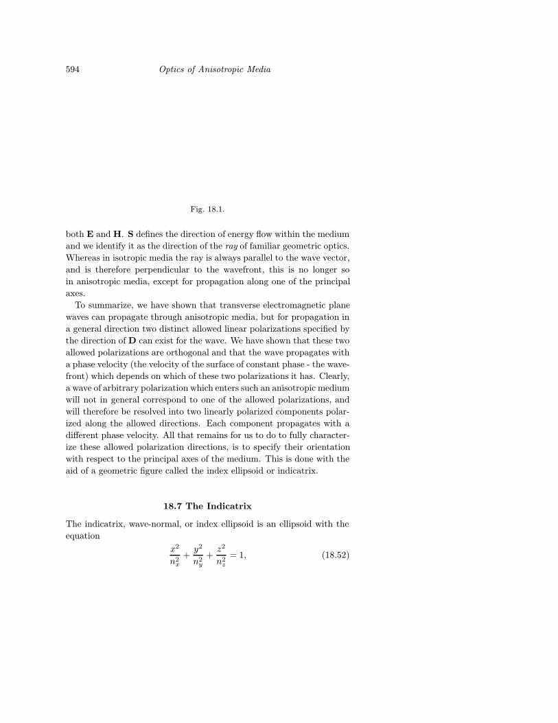
These angular relationships are illustrated in Fig. (18.1). The direction
of the Poynting vector S = E×H is, by definition, perpendicular to
594 Optics of Anisotropic Media
Fig. 18.1.
both E and H. S defines the direction of energy flow within the medium
and we identify it as the direction of the ray of familiar geometric optics.
Whereas in isotropic media the ray is always parallel to the wave vector,
and is therefore perpendicular to the wavefront, this is no longer so
in anisotropic media, except for propagation along one of the principal
axes.
To summarize, we have shown that transverse electromagnetic plane
waves can propagate through anisotropic media, but for propagation in
a general direction two distinct allowed linear polarizations specified by
the direction of D can exist for the wave. We have shown that these two
allowed polarizations are orthogonal and that the wave propagates with
a phase velocity (the velocity of the surface of constant phase - the wave-
front) which depends on which of these two polarizations it has. Clearly,
a wave of arbitrary polarization which enters such an anisotropic medium
will not in general correspond to one of the allowed polarizations, and
will therefore be resolved into two linearly polarized components polar-
ized along the allowed directions. Each component propagates with a
different phase velocity. All that remains for us to do to fully character-
ize these allowed polarization directions, is to specify their orientation
with respect to the principal axes of the medium. This is done with the
aid of a geometric figure called the index ellipsoid or indicatrix.
18.7 The Indicatrix
The indicatrix, wave-normal, or index ellipsoid is an ellipsoid with the
equation
x2
n2x
+y2
n2y
+z2
n2z
= 1, (18.52)
The Indicatrix 595
which allows us to determine the refractive index for monochromatic
plane waves as a function of their direction of polarization. It is, apart
from a scale factor, equivalent to the surface mapped out by the D vec-
tors corresponding to a constant energy density at a given frequency.
This ellipsoid can be visualized as oriented inside a crystal consistent
with the symmetry axes of the crystal. For example, in any crystal
with perpendicular symmetry axes, such as those belonging to the cu-
bic, tetragonal, hexagonal, trigonal or orthorhombic crystal systems, the
axes of the ellipsoid, which are the principal axes of the crystal, are par-
allel to the three axes of symmetry of the crystal. For the orientation of
the indicatrix to be consistent with the symmetry of the crystal, planes of
mirror symmetry within the crystal must coincide with planes of symme-
try of the indicatrix: namely the xy, yz and zx planes. In the monoclinic
system, crystal symmetry is referred to three axes, two of which, the a
and c axes of crystallographic terminology, intersect at acute and obtuse
angles and a third, the b axis, is perpendicular to the a and c axes. In
such crystals, one of the axes of the indicatrix must coincide with the b
axis, but the other two axes have any orientation, although this is fixed
for a given crystal and wavelength. In triclinic crystals whose symmetry
is referred to three unequal length, non-orthogonal axes, the indicatrix
can take any orientation, although this is fixed for a given crystal and
wavelength.
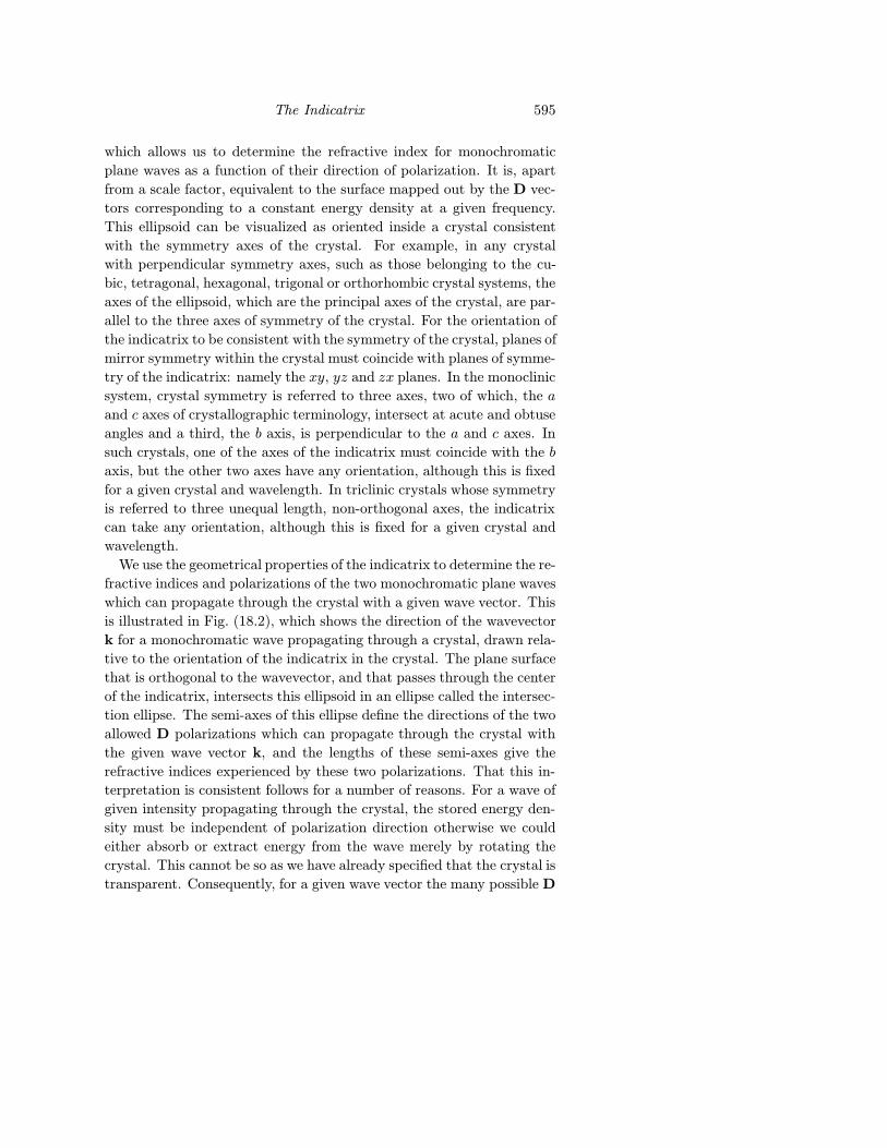
We use the geometrical properties of the indicatrix to determine the re-
fractive indices and polarizations of the two monochromatic plane waves
which can propagate through the crystal with a given wave vector. This
is illustrated in Fig. (18.2), which shows the direction of the wavevector
k for a monochromatic wave propagating through a crystal, drawn rela-
tive to the orientation of the indicatrix in the crystal. The plane surface
that is orthogonal to the wavevector, and that passes through the center
of the indicatrix, intersects this ellipsoid in an ellipse called the intersec-
tion ellipse. The semi-axes of this ellipse define the directions of the two
allowed D polarizations which can propagate through the crystal with
the given wave vector k, and the lengths of these semi-axes give the
refractive indices experienced by these two polarizations. That this in-
terpretation is consistent follows for a number of reasons. For a wave of
given intensity propagating through the crystal, the stored energy den-
sity must be independent of polarization direction otherwise we could
either absorb or extract energy from the wave merely by rotating the
crystal. This cannot be so as we have already specified that the crystal is
transparent. Consequently, for a given wave vector the many possible D
596 Optics of Anisotropic Media
Fig. 18.2.
polarizations trace out an ellipse, equivalent to the intersection ellipse.
Further, it can be shown that the lengths of the semiaxes of the intersec-tion ellipse corresponding to a given wavevector k = kx ı+ ky + kzk are
the two roots n1 and n2 of Fresnel’s Eq. (18.39). Thus, only the two D
vectors parallel to these semiaxes simultaneously satisfy the condition of
both being on the ellipse and having the appropriate refractive indices
to satisfy Fresnel’s equations.
In the general case there are two k vector directions through the center
of the indicatrix for which the intersection ellipse is a circle. This is a
fundamental geometric property of ellipsoids. These two directions are
called the principal optic axes and are fixed for a given crystal and
frequency of light. Waves can propagate along these optic axes with any
arbitrary polarization, as in these directions the refractive index is not
a function of polarization.
In cubic crystals the indicatrix is a sphere called the isotropic indica-
trix, there are no specific optic axes as the indicatrix is anaxial and the
propagation of waves is independent of both the directions of k and D.
In crystals belonging to the tetragonal, hexagonal and trigonal crystal
systems the crystal symmetry requires that nx = ny and the indicatrix
reduces to an ellipsoid of revolution. In this case there is only one optic
axis, oriented along the axis of highest symmetry of the crystal, the z
axis (or c axis). These crystals classes, listed in Table (18.1), are said to
be uniaxial: a discussion of their properties is considerably simpler than
for crystals belonging to the less symmetric orthohombic, monoclinic
and triclinic crystal systems, which are biaxial.
18.8 Uniaxial Crystals
Uniaxial Crystals 597
Table 18.1 Uniaxial Crystal Classes
Hexagonal Trigonal Tetragonal
62m 3m 42m6mm 32 4mm622 3 4226 46 4
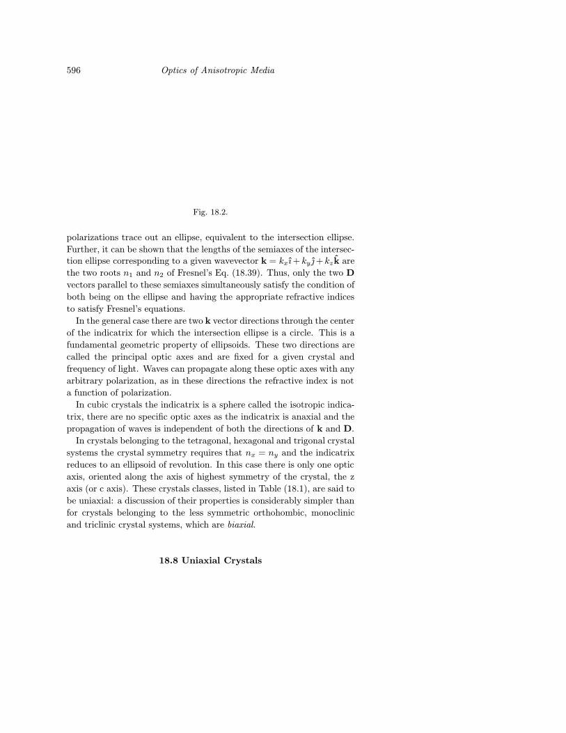
Fig. 18.3.
The equation of the uniaxial indicatrix is
x2 + y2
n2o
+z2
n2e
= 1 (18.53)
where no is the index of refraction experienced by waves polarized per-
pendicular to the optic axis, called ordinary or O - waves; ne is the index
of refraction experienced by waves polarized parallel to the optic axis,
called extraordinary or E - waves. If ne > no the indicatrix is a prolate
ellipsoid of revolution as shown in Fig. (18.3) and such a crystal is said
to be positive uniaxial.
If ne < no the indicatrix is an oblate ellipsoid of revolution as shown
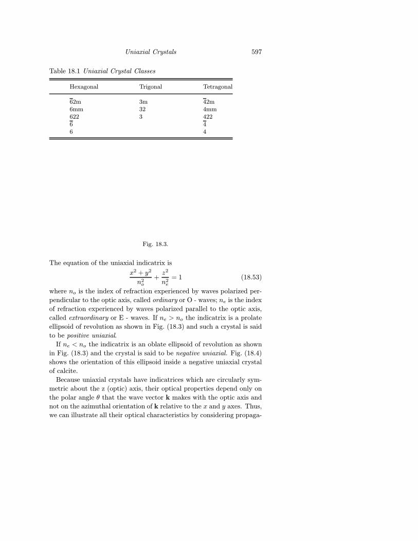
in Fig. (18.3) and the crystal is said to be negative uniaxial. Fig. (18.4)
shows the orientation of this ellipsoid inside a negative uniaxial crystal
of calcite.
Because uniaxial crystals have indicatrices which are circularly sym-
metric about the z (optic) axis, their optical properties depend only on
the polar angle θ that the wave vector k makes with the optic axis and
not on the azimuthal orientation of k relative to the x and y axes. Thus,
we can illustrate all their optical characteristics by considering propaga-
598 Optics of Anisotropic Media
Fig. 18.4.
Fig. 18.5.
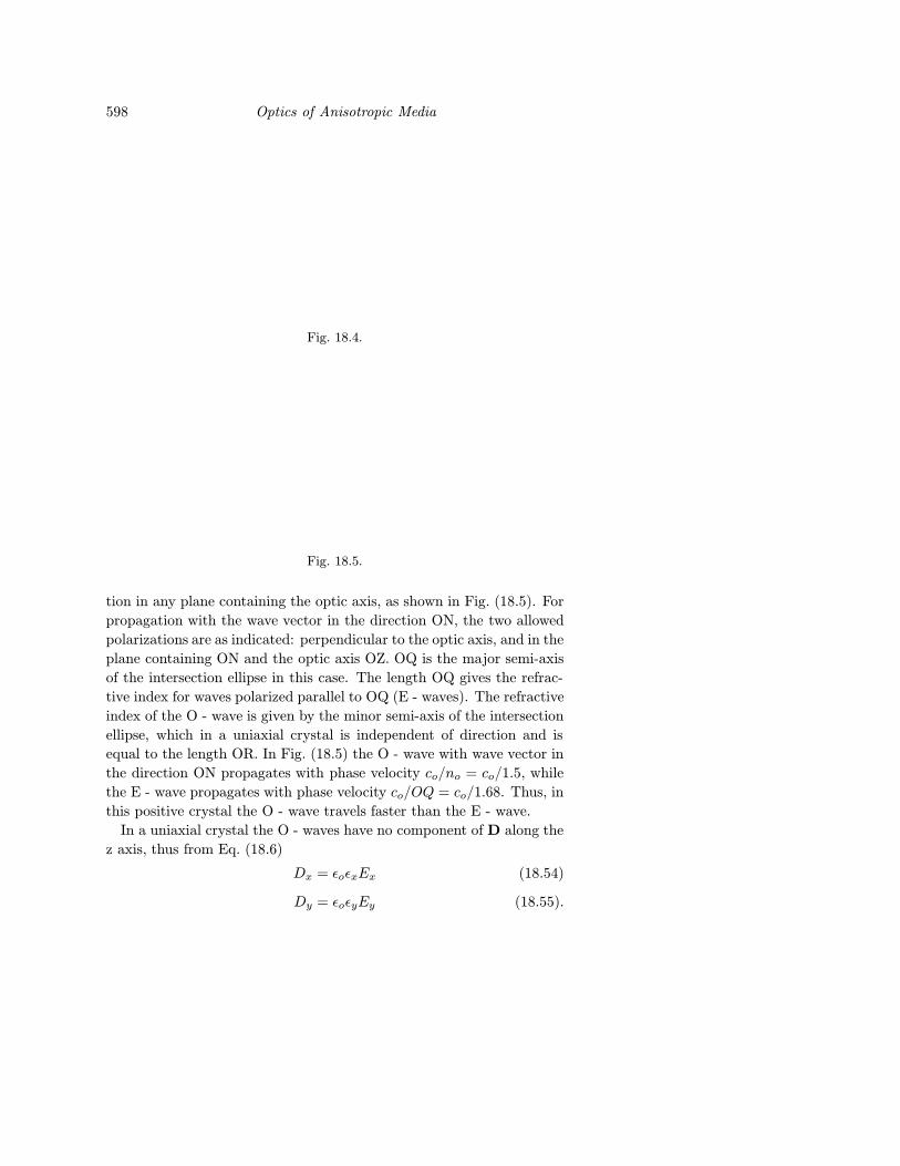
tion in any plane containing the optic axis, as shown in Fig. (18.5). For
propagation with the wave vector in the direction ON, the two allowed
polarizations are as indicated: perpendicular to the optic axis, and in the
plane containing ON and the optic axis OZ. OQ is the major semi-axis
of the intersection ellipse in this case. The length OQ gives the refrac-
tive index for waves polarized parallel to OQ (E - waves). The refractive
index of the O - wave is given by the minor semi-axis of the intersection
ellipse, which in a uniaxial crystal is independent of direction and is
equal to the length OR. In Fig. (18.5) the O - wave with wave vector in
the direction ON propagates with phase velocity co/no = co/1.5, while
the E - wave propagates with phase velocity co/OQ = co/1.68. Thus, in
this positive crystal the O - wave travels faster than the E - wave.
In a uniaxial crystal the O - waves have no component of D along the
z axis, thus from Eq. (18.6)
Dx = εoεxEx (18.54)
Dy = εoεyEy (18.55).
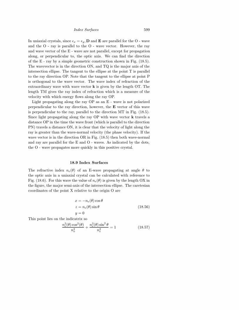
Index Surfaces 599
In uniaxial crystals, since εx = εy,D and E are parallel for the O - wave
and the O - ray is parallel to the O - wave vector. However, the ray
and wave vector of the E - wave are not parallel, except for propagation
along, or perpendicular to, the optic axis. We can find the direction
of the E - ray by a simple geometric construction shown in Fig. (18.5).
The wavevector is in the direction ON, and TQ is the major axis of the
intersection ellipse. The tangent to the ellipse at the point T is parallel
to the ray direction OP. Note that the tangent to the ellipse at point P
is orthogonal to the wave vector. The wave index of refraction of the
extraordinary wave with wave vector k is given by the length OT. The
length TM gives the ray index of refraction which is a measure of the
velocity with which energy flows along the ray OP.
Light propagating along the ray OP as an E - wave is not polarized
perpendicular to the ray direction, however, the E vector of this wave
is perpendicular to the ray, parallel to the direction MT in Fig. (18.5).
Since light propagating along the ray OP with wave vector k travels a
distance OP in the time the wave front (which is parallel to the direction
PN) travels a distance ON, it is clear that the velocity of light along the
ray is greater than the wave-normal velocity (the phase velocity). If the
wave vector is in the direction OR in Fig. (18.5) then both wave-normal
and ray are parallel for the E and O - waves. As indicated by the dots,
the O - wave propagates more quickly in this positive crystal.
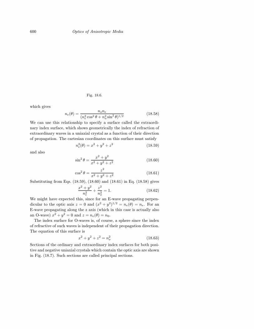
18.9 Index Surfaces
The refractive index ne(θ) of an E-wave propagating at angle θ to
the optic axis in a uniaxial crystal can be calculated with reference to
Fig. (18.6). For this wave the value of ne(θ) is given by the length OX in
the figure, the major semi-axis of the intersection ellipse. The caretesian
coordinates of the point X relative to the origin O are
x = −ne(θ) cos θ
z = ne(θ) sin θ
y = 0
(18.56)
This point lies on the indicatrix so
n2e(θ) cos2(θ)
n2o
+n2e(θ) sin2 θ
n2e
= 1 (18.57)
600 Optics of Anisotropic Media
Fig. 18.6.
which gives
ne(θ) =none
(n2e cos2 θ + n2
o sin2 θ)1/2(18.58)
We can use this relationship to specify a surface called the extraordi-
nary index surface, which shows geometrically the index of refraction of
extraordinary waves in a uniaxial crystal as a function of their direction
of propagation. The cartesian coordinates on this surface must satisfy
n2e(θ) = x2 + y2 + z2 (18.59)
and also
sin2 θ =x2 + y2
x2 + y2 + z2(18.60)
cos2 θ =z2
x2 + y2 + z2(18.61)
Substituting from Eqs. (18.59), (18.60) and (18.61) in Eq. (18.58) gives
x2 + y2
n2e
+z2
n2o
= 1. (18.62)
We might have expected this, since for an E-wave propagating perpen-
dicular to the optic axis z = 0 and (x2 + y2)1/2 = ne(θ) = ne. For an
E-wave propagating along the z axis (which in this case is actually also
an O-wave) x2 + y2 = 0 and z = ne(θ) = n0.
The index surface for O-waves is, of course, a sphere since the index
of refractive of such waves is independent of their propagation direction.
The equation of this surface is
x2 + y2 + z2 = n2o (18.63)
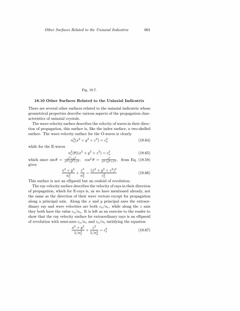
Sections of the ordinary and extraordinary index surfaces for both posi-
tive and negative uniaxial crystals which contain the optic axis are shown
in Fig. (18.7). Such sections are called principal sections.
Other Surfaces Related to the Uniaxial Indicatrix 601
Fig. 18.7.
18.10 Other Surfaces Related to the Uniaxial Indicatrix
There are several other surfaces related to the uniaxial indicatrix whose
geometrical properties describe various aspects of the propagation char-
acteristics of uniaxial crystals.
The wave-velocity surface describes the velocity of waves in their direc-
tion of propagation, this surface is, like the index surface, a two-shelled
surface. The wave-velocity surface for the O-waves is clearly
n2o(x
2 + y2 + z2) = c2o (18.64)
while for the E-waves
n2e(θ)(x
2 + y2 + z2) = c2o (18.65)
which since sin θ = x2+y2
x2+y2+z2 ; cos2 θ = z2
x2+y2+z2 , from Eq. (18.58)gives
x2 + y2
n2e
+z2
n2o
=(x2 + y2 + z2)2
c2o(18.66)
This surface is not an ellipsoid but an ovaloid of revolution.
The ray-velocity surface describes the velocity of rays in their direction
of propagation, which for E-rays is, as we have mentioned already, not
the same as the direction of their wave vectors except for propagation
along a principal axis. Along the x and y principal axes the extraor-
dinary ray and wave velocities are both co/ne, while along the z axis
they both have the value co/no. It is left as an exercise to the reader to
show that the ray velocity surface for extraordinary rays is an ellipsoid
of revolution with semi-axes co/ne and co/ne satisfying the equation
x2 + y2
1/n2e
+z2
1/n2o
= c2o (18.67)
602 Optics of Anisotropic Media
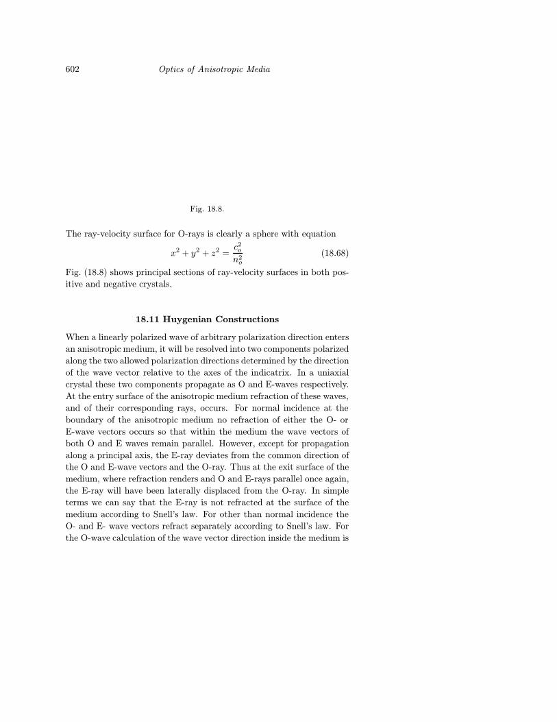
Fig. 18.8.
The ray-velocity surface for O-rays is clearly a sphere with equation
x2 + y2 + z2 =c2on2o
(18.68)
Fig. (18.8) shows principal sections of ray-velocity surfaces in both pos-
itive and negative crystals.
18.11 Huygenian Constructions
When a linearly polarized wave of arbitrary polarization direction enters
an anisotropic medium, it will be resolved into two components polarized
along the two allowed polarization directions determined by the direction
of the wave vector relative to the axes of the indicatrix. In a uniaxial
crystal these two components propagate as O and E-waves respectively.
At the entry surface of the anisotropic medium refraction of these waves,
and of their corresponding rays, occurs. For normal incidence at the
boundary of the anisotropic medium no refraction of either the O- or
E-wave vectors occurs so that within the medium the wave vectors of
both O and E waves remain parallel. However, except for propagation
along a principal axis, the E-ray deviates from the common direction of
the O and E-wave vectors and the O-ray. Thus at the exit surface of the
medium, where refraction renders and O and E-rays parallel once again,
the E-ray will have been laterally displaced from the O-ray. In simple
terms we can say that the E-ray is not refracted at the surface of the
medium according to Snell’s law. For other than normal incidence the
O- and E- wave vectors refract separately according to Snell’s law. For
the O-wave calculation of the wave vector direction inside the medium is
Huygenian Constructions 603
straightforward. For angle of incidence θi the angle of refraction obeys
sin θi = no sin θr
However, for the E-wave the refraction of the wave vector obeys
sin θi = ne(θ) sin θr
where θ is the angle that the refracted wave vector makes with the
optic axis. To illustrate these geometric optical properties of anisotropic
media it is instructive to use Huygenian constructions using the ray-
velocity surfaces for the O and E-rays. In Huygenian constructions we
treat each point on the entrance boundary of the anisotropic media
as a secondary emitter of electromagnetic waves. In a given time the
distance travelled by all the O or E-rays leaving this point as a function of
direction traces out the appropriate ray velocity surface. The geometric
paths of the O and E-rays are perpendicular to the envelope of the
ray velocity surfaces which arise from these secondary emitters. To
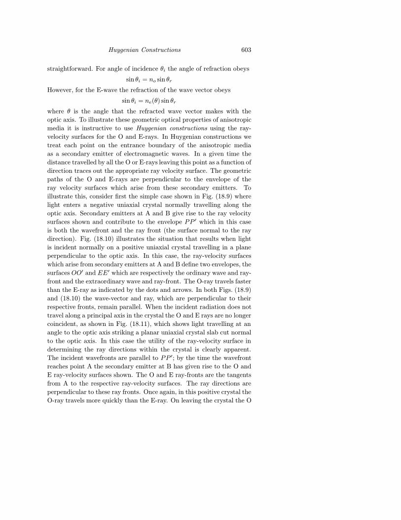
illustrate this, consider first the simple case shown in Fig. (18.9) where
light enters a negative uniaxial crystal normally travelling along the
optic axis. Secondary emitters at A and B give rise to the ray velocity
surfaces shown and contribute to the envelope PP ′ which in this case
is both the wavefront and the ray front (the surface normal to the ray
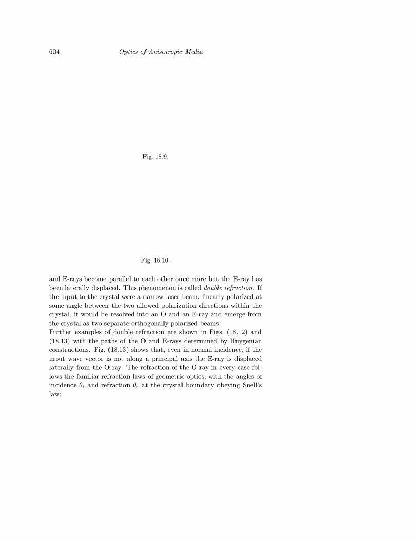
direction). Fig. (18.10) illustrates the situation that results when light
is incident normally on a positive uniaxial crystal travelling in a plane
perpendicular to the optic axis. In this case, the ray-velocity surfaces
which arise from secondary emitters at A and B define two envelopes, the
surfaces OO′ and EE′ which are respectively the ordinary wave and ray-
front and the extraordinary wave and ray-front. The O-ray travels faster
than the E-ray as indicated by the dots and arrows. In both Figs. (18.9)
and (18.10) the wave-vector and ray, which are perpendicular to their
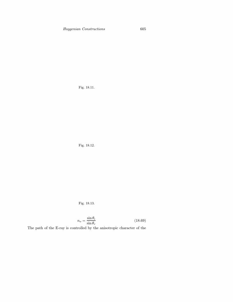
respective fronts, remain parallel. When the incident radiation does not
travel along a principal axis in the crystal the O and E rays are no longer
coincident, as shown in Fig. (18.11), which shows light travelling at an
angle to the optic axis striking a planar uniaxial crystal slab cut normal
to the optic axis. In this case the utility of the ray-velocity surface in
determining the ray directions within the crystal is clearly apparent.
The incident wavefronts are parallel to PP ′; by the time the wavefront
reaches point A the secondary emitter at B has given rise to the O and
E ray-velocity surfaces shown. The O and E ray-fronts are the tangents
from A to the respective ray-velocity surfaces. The ray directions are
perpendicular to these ray fronts. Once again, in this positive crystal the
O-ray travels more quickly than the E-ray. On leaving the crystal the O
604 Optics of Anisotropic Media
Fig. 18.9.
Fig. 18.10.
and E-rays become parallel to each other once more but the E-ray has
been laterally displaced. This phenomenon is called double refraction. If
the input to the crystal were a narrow laser beam, linearly polarized at
some angle between the two allowed polarization directions within the
crystal, it would be resolved into an O and an E-ray and emerge from
the crystal as two separate orthogonally polarized beams.
Further examples of double refraction are shown in Figs. (18.12) and
(18.13) with the paths of the O and E-rays determined by Huygenian
constructions. Fig. (18.13) shows that, even in normal incidence, if the
input wave vector is not along a principal axis the E-ray is displaced
laterally from the O-ray. The refraction of the O-ray in every case fol-
lows the familiar refraction laws of geometric optics, with the angles of
incidence θi and refraction θr at the crystal boundary obeying Snell’s
law:
Huygenian Constructions 605
Fig. 18.11.
Fig. 18.12.
Fig. 18.13.
no =sin θisin θr
(18.69)
The path of the E-ray is controlled by the anisotropic character of the
606 Optics of Anisotropic Media
Fig. 18.14.
medium and must be determined from a non-spherical ray-velocity sur-
face.
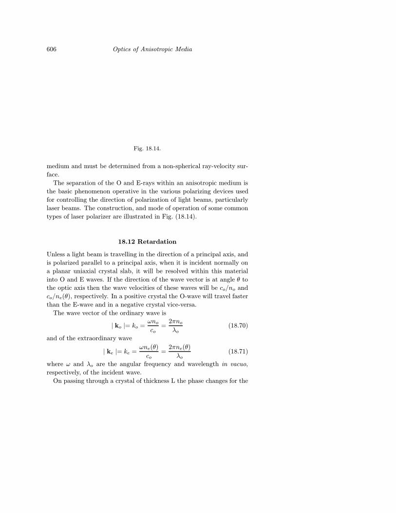
The separation of the O and E-rays within an anisotropic medium is
the basic phenomenon operative in the various polarizing devices used
for controlling the direction of polarization of light beams, particularly
laser beams. The construction, and mode of operation of some common
types of laser polarizer are illustrated in Fig. (18.14).
18.12 Retardation
Unless a light beam is travelling in the direction of a principal axis, and
is polarized parallel to a principal axis, when it is incident normally on
a planar uniaxial crystal slab, it will be resolved within this material
into O and E waves. If the direction of the wave vector is at angle θ to
the optic axis then the wave velocities of these waves will be co/no and
co/ne(θ), respectively. In a positive crystal the O-wave will travel faster
than the E-wave and in a negative crystal vice-versa.
The wave vector of the ordinary wave is
| ko |= ko =ωno
co=
2πnoλo
(18.70)
and of the extraordinary wave
| ke |= ke =ωne(θ)
co=
2πne(θ)
λo(18.71)
where ω and λo are the angular frequency and wavelength in vacuo,
respectively, of the incident wave.
On passing through a crystal of thickness L the phase changes for the
Retardation 607
O and E-waves, respectively, are
φo = koL =2πnoL
λo(18.72)
φe = keL =2πne(θ)L
λo(18.73)
The phase difference (retardation) introduced by the crystal is
∆φ = φe − φo =2πL
λo(ne(θ) − no) (18.74)
For an incident wave of the form
D = A cos(ωt− kr) (18.75)
linearly polarized at an angle β to the ordinary polarization direction,
The ordinary and extraordinary waves will be
Do = A cosβ cos(ωt− kor) (18.76)
De = A sinβ cos(ωt− ker) (18.77)
and at the exit face of the crystal
Do = A cosβ cos(ωt− φo) (18.78)
De = A sinβ cos(ωt− φe) (18.79)
If the input to the crystal is a narrow beam of light, these two orthogo-
nally polarized output beams will in general be displaced laterally from
one another and will not recombine to form a single output beam. How-
ever, if the input to the crystal is a plane wave, or a narrow beam travel-
ling perpendicular to the optic axis, these two electric vectors recombine
to form a resultant single displacement vector with magnitude
Dout = (D2o +D2
e)1/2 (18.80)
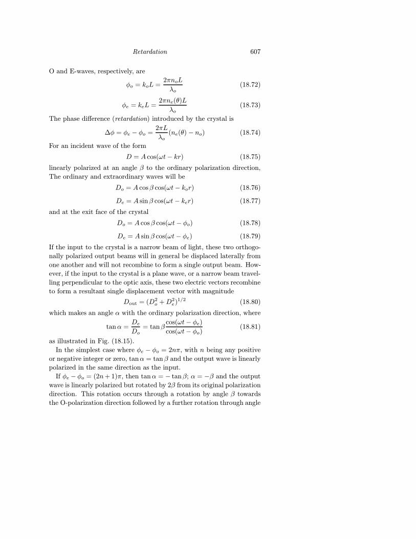
which makes an angle α with the ordinary polarization direction, where
tanα =De
Do= tanβ
cos(ωt− φe)cos(ωt− φo)
(18.81)
as illustrated in Fig. (18.15).
In the simplest case where φe − φo = 2nπ, with n being any positive
or negative integer or zero, tanα = tanβ and the output wave is linearly
polarized in the same direction as the input.
If φe − φo = (2n+ 1)π, then tanα = − tanβ; α = −β and the output
wave is linearly polarized but rotated by 2β from its original polarization
direction. This rotation occurs through a rotation by angle β towards
the O-polarization direction followed by a further rotation through angle
608 Optics of Anisotropic Media
Fig. 18.15.
β *. Since a retardation φ = (2n+ 1)π is equivalent to a path difference
of (2n + 1)λ/2 a crystal which rotates the plane of linear polarization
by 2β is called a ((2n + 1)th order) half-wave (retardation) plate. It
is most usual to cut such a crystal so its faces are parallel to the optic
axis and to polarize the input at 45◦ to the optic axis, in which case the
output is linearly polarized and rotated 90◦ from the input. When the
input is polarized in this manner and φ = φe − φo = (2n + 1)π/2 then
tanα = ± tan(ωt− φo).For n even tanα = ωt− φo.For n odd tanα = −(ωt− φo).In both these cases the resultant displacement vector has magnitude,
from Eqs. (18.78), (18.79) and (18.80), with β = 45◦
Dout =A√2
[cos2(ωt+ φo) + cos2(ωt− φo − φ)]
=A√2
(18.82)
so the output displacement vector has a constant magnitude but ro-
tates about the direction of propagation with constant angular velocity
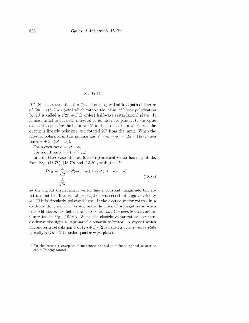
ω. This is circularly polarized light. If the electric vector rotates in a
clockwise direction when viewed in the direction of propagation, as when
n is odd above, the light is said to be left-hand circularly polarized, as
illustrated in Fig. (18.16). When the electric vector rotates counter-
clockwise the light is right-hand circularly polarized. A crystal which
introduces a retardation φ of (2n+ 1)π/2 is called a quarter-wave plate
(strictly a (2n+ 1)th order quarter-wave plate).
* For this reason a waveplate alone cannot be used to make an optical isolator ascan a Faraday rotator.
Retardation 609
Fig. 18.16.
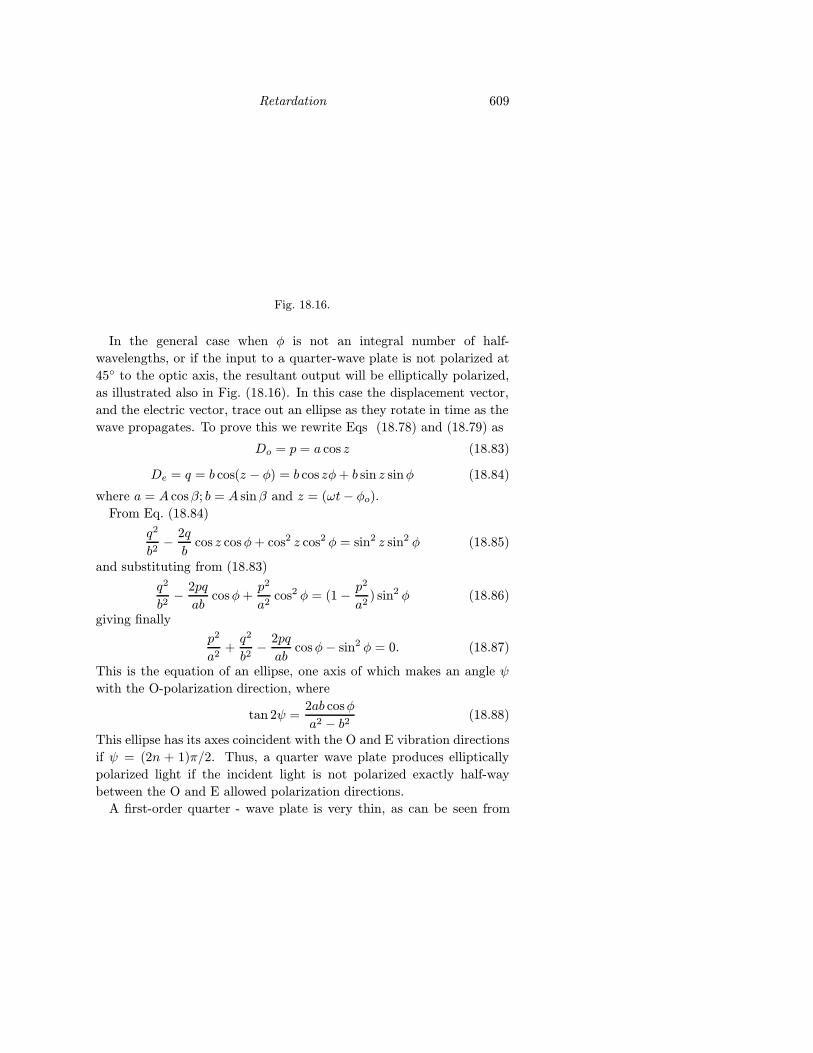
In the general case when φ is not an integral number of half-
wavelengths, or if the input to a quarter-wave plate is not polarized at
45◦ to the optic axis, the resultant output will be elliptically polarized,
as illustrated also in Fig. (18.16). In this case the displacement vector,
and the electric vector, trace out an ellipse as they rotate in time as the
wave propagates. To prove this we rewrite Eqs (18.78) and (18.79) as
Do = p = a cos z (18.83)
De = q = b cos(z − φ) = b cos zφ+ b sin z sinφ (18.84)
where a = A cosβ; b = A sinβ and z = (ωt− φo).From Eq. (18.84)
q2
b2− 2q
bcos z cosφ+ cos2 z cos2 φ = sin2 z sin2 φ (18.85)
and substituting from (18.83)
q2
b2− 2pq
abcosφ+
p2
a2cos2 φ = (1− p2
a2) sin2 φ (18.86)
giving finally
p2
a2+q2
b2− 2pq
abcosφ− sin2 φ = 0. (18.87)
This is the equation of an ellipse, one axis of which makes an angle ψ
with the O-polarization direction, where
tan 2ψ =2ab cosφ
a2 − b2 (18.88)
This ellipse has its axes coincident with the O and E vibration directions
if ψ = (2n + 1)π/2. Thus, a quarter wave plate produces elliptically
polarized light if the incident light is not polarized exactly half-way
between the O and E allowed polarization directions.
A first-order quarter - wave plate is very thin, as can be seen from
610 Optics of Anisotropic Media
Eq. (18.74), its thickness L is
L =λo
4(ne − no)(18.89)
For calcite (Iceland spar), a mineral form of calcium carbonate that is
commonly used to make polarizing optics no = 1.658, ne = 1.486. so for
a wavelength of 500 nm the thickness of a first-order quarter-wave plate
is only 726.7nm ∼ 0.0007 mm. It is not practical to cut a crystalline
slab so thin as this, except for a birefringent material such as mica
which cleaves readily into very thin slices. (2n + 1)th-order quarter-
wave plates can be of practical thickness for large values of n but suffer
severely from the effects of termperature: the plate only has to expand
or contract very slightly and it will cease to be a quarter-wave plate at
the wavelength for which it was designed. To overcome this drawback,
temperature compensated plates can be made. These consist of one
(2n + 1) th-order quarter-wave plate stacked on top of a plate which
produces a retardation of nπ but whose optic axis is perpendicular to
the optic axis (E-wave polarization direction) of the quarter-wave plate.
The total retardation of the combination is
φ = φ1 − φ2 = (2n+ 1)π/2− nπ = π/2 (18.95)
so it is equivalent to a first-order quarter-wave plate but is not sensitive
to temperature changes.
18.13 Biaxial Crystals
The optical properties of biaxial crystals can be related to an ellipsoid
with three unequal axes, the biaxial indicatrix, whose equation is
x2
n2x
+y2
n2y
+z2
n2z
= 1 (18.96)
where nx, ny and nz are the three principal refractive indices of the
material. It is the normal convention to label the axes so that nx < ny <
nz. When this is done the two optic axes, those directions through the
crystal along which the direction of propagation of waves is independent
of their polarization direction, lie in the xz plane. If the two optic axes
are closer to the z axis then the x axis the crystal is said to be positive,
otherwise it is negative. Some of the important features of positive
and negative biaxial indicatrices are illustrated in Fig. (18.17). The
acute angle between the two optic axes is labelled 2V - the optic angle.
Whichever axis bisects this acute angle is called the acute bisectrix, this
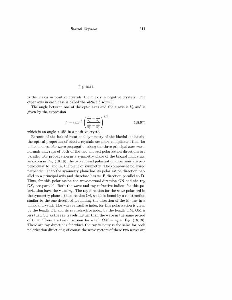
Biaxial Crystals 611
Fig. 18.17.
is the z axis in positive crystals, the x axis in negative crystals. The
other axis in each case is called the obtuse bisectrix.
The angle between one of the optic axes and the z axis is Vz and is
given by the expression
Vz = tan−1
( 1n2x− 1
n2y
1n2y− 1
n2z
)1/2
(18.97)
which is an angle < 45◦ in a positive crystal.
Because of the lack of rotational symmetry of the biaxial indicatrix,
the optical properties of biaxial crystals are more complicated than for
uniaxial ones. For wave propagation along the three principal axes wave-
normals and rays of both of the two allowed polarization directions are
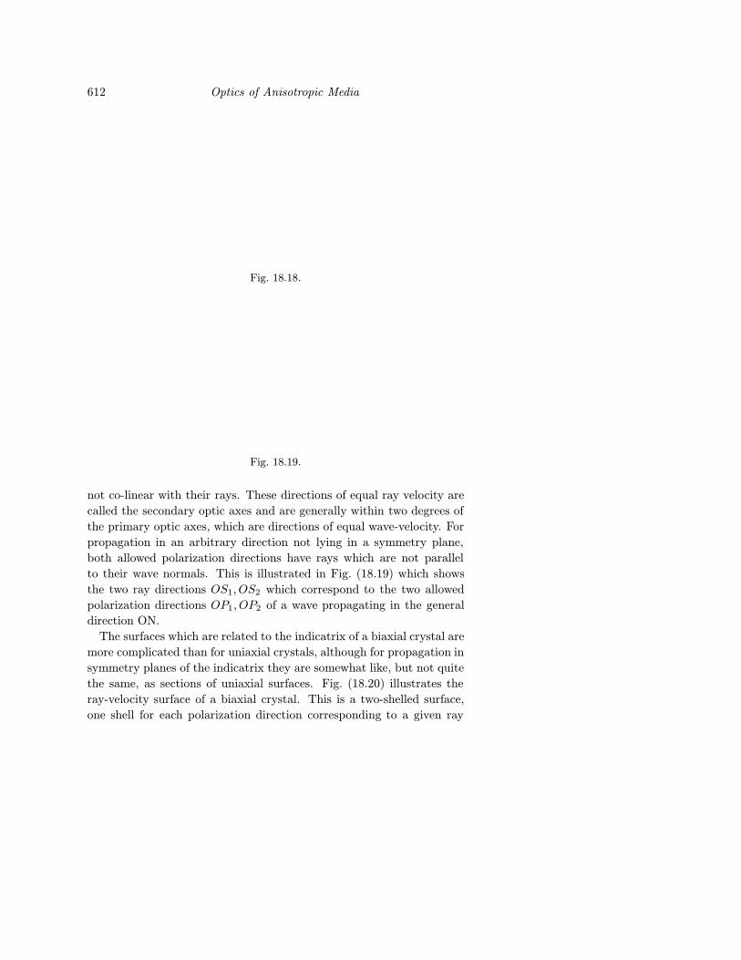
parallel. For propagation in a symmetry plane of the biaxial indicatrix,
as shown in Fig. (18.18), the two allowed polarization directions are per-
pendicular to, and in, the plane of symmetry. The component polarized
perpendicular to the symmetry plane has its polarization direction par-
allel to a principal axis and therefore has its E direction parallel to D.
Thus, for this polarization the wave-normal direction ON and the ray
OS1 are parallel. Both the wave and ray refractive indices for this po-
larization have the value ny. The ray direction for the wave polarized in
the symmetry plane is the direction OS, which is found by a construction
similar to the one described for finding the direction of the E - ray in a
uniaxial crystal. The wave refractive index for this polarization is given
by the length OT and its ray refractive index by the length OM; OM is
less than OT as the ray travels further than the wave in the same period
of time. There are two directions for which OM = ny in Fig. (18.18).
These are ray directions for which the ray velocity is the same for both
polarization directions; of course the wave vectors of these two waves are
612 Optics of Anisotropic Media
Fig. 18.18.
Fig. 18.19.
not co-linear with their rays. These directions of equal ray velocity are
called the secondary optic axes and are generally within two degrees of
the primary optic axes, which are directions of equal wave-velocity. For
propagation in an arbitrary direction not lying in a symmetry plane,
both allowed polarization directions have rays which are not parallel
to their wave normals. This is illustrated in Fig. (18.19) which shows
the two ray directions OS1, OS2 which correspond to the two allowed
polarization directions OP1, OP2 of a wave propagating in the general
direction ON.
The surfaces which are related to the indicatrix of a biaxial crystal are
more complicated than for uniaxial crystals, although for propagation in
symmetry planes of the indicatrix they are somewhat like, but not quite
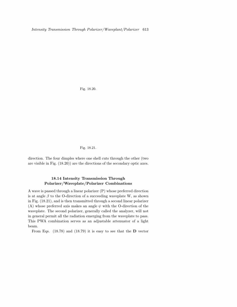
the same, as sections of uniaxial surfaces. Fig. (18.20) illustrates the
ray-velocity surface of a biaxial crystal. This is a two-shelled surface,
one shell for each polarization direction corresponding to a given ray
Intensity Transmission Through Polarizer/Waveplant/Polarizer 613
Fig. 18.20.
Fig. 18.21.
direction. The four dimples where one shell cuts through the other (two
are visible in Fig. (18.20)) are the directions of the secondary optic axes.
18.14 Intensity Transmission Through
Polarizer/Waveplate/Polarizer Combinations
A wave is passed through a linear polarizer (P) whose preferred direction
is at angle β to the O-direction of a succeeding waveplate W, as shown
in Fig. (18.21), and is then transmitted through a second linear polarizer
(A) whose preferred axis makes an angle ψ with the O-direction of the
waveplate. The second polarizer, generally called the analyzer, will not
in general permit all the radiation emerging from the waveplate to pass.
This PWA combination serves as an adjustable attenuator of a light
beam.
From Eqs. (18.78) and (18.79) it is easy to see that the D vector
614 Optics of Anisotropic Media
transmitted through the analyzer has magnitude
D = A cosβ cos(ωt− φ0) cosψ +A sinβ cos(ωt− φe) sinψ (18.98)
which can be rearranged to give
D = D0 cos(ωt− φe + χ) (18.99)
where
D0 = A[(cosβ cosψ cos ∆φ+ sinβ sinψ)2 + (cos β cosψ sin ∆φ)2]1/2
(18.100)
and
tanχ =cosβ cosψ sin ∆φ
cosβ cosψ cos ∆φ+ sinβ sinψ(18.101)
∆φ = φe − φ0 is the retardation produced by the wave plate.
Examples 615
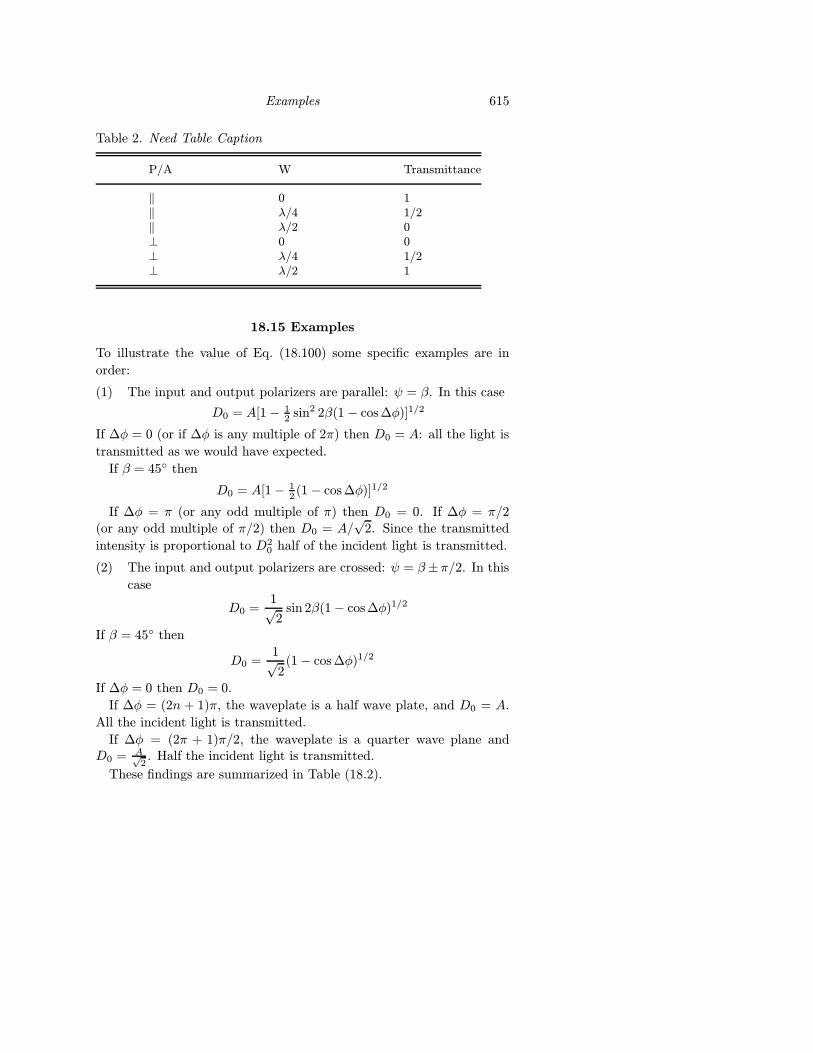
Table 2. Need Table Caption
P/A W Transmittance
‖ 0 1‖ λ/4 1/2‖ λ/2 0⊥ 0 0⊥ λ/4 1/2⊥ λ/2 1
18.15 Examples
To illustrate the value of Eq. (18.100) some specific examples are in
order:
(1) The input and output polarizers are parallel: ψ = β. In this case
D0 = A[1− 12 sin2 2β(1− cos ∆φ)]1/2
If ∆φ = 0 (or if ∆φ is any multiple of 2π) then D0 = A: all the light is
transmitted as we would have expected.
If β = 45◦ then
D0 = A[1− 12 (1− cos ∆φ)]1/2
If ∆φ = π (or any odd multiple of π) then D0 = 0. If ∆φ = π/2(or any odd multiple of π/2) then D0 = A/
√2. Since the transmitted
intensity is proportional to D20 half of the incident light is transmitted.
(2) The input and output polarizers are crossed: ψ = β±π/2. In this
case
D0 =1√2
sin 2β(1− cos ∆φ)1/2
If β = 45◦ then
D0 =1√2
(1− cos ∆φ)1/2
If ∆φ = 0 then D0 = 0.
If ∆φ = (2n + 1)π, the waveplate is a half wave plate, and D0 = A.
All the incident light is transmitted.
If ∆φ = (2π + 1)π/2, the waveplate is a quarter wave plane andD0 = A√
2. Half the incident light is transmitted.
These findings are summarized in Table (18.2).
616 Optics of Anisotropic Media
18.16 The Jones Calculus
Over fifty years ago R. Clark Jones described a very useful technique
for describing the change in polarization state of light wave as it passed
through an optical system containing various interfaces and polarizing
elements.[18. ] The Jones Calculus treats the optical system as a linear
system describable by an appropriate Jones matrix that transforms vec-
tors describing the polarization state of the wave. In this sense the Jones
Calculus is analogous to paraxial ray analysis.
18.16.1 The Jones Vector
The electric field of a light wave linearly polarized along the x axis can
be written as
Ex = Ax sin(ωt+ φx)', (18.102)
which is complex exponential notation is
Ex = Axeiφxeiωt. (18.103)
On the other hand a light wave linearly polarized along the y axis can
be written as
Ey = Ayeiφyeiωt (18.104)
The superposition of the electric fields Ex and Ey leads in general to
elliptically polarized light with electric field
E =(Axe
iφx +Ayeiφy)eiωt (18.105)
The complex amplitudes of the x and y components of this wave form
the 2 elements of the Jones vector J, where
J =
(Axe
iφx
Ayeiφy
)(18.106)
Clearly, light linearly polarized along the x axis has
J =
(Axe
iφx
0
)(18.107)
with a similar result for linearly polarized along y.
Light linearly polarized at angle β to the axis has
Jβ =
(E0 cosβE0 sinβ
)(18.108)
Right handd cciircularly polarized light has
Jrcp =
(E0e
iφx
E0ei(φx+π/2)
)(18.109)
The Jones Calculus 617
and left hand circularly polarized light has
Jrcp =
(E0e
iφx
E0ei(φx−π/2)
)(18.110)
In an isotopic medium the intensity of the wave is
IαE∗ ·E, (18.111)
which in terms of the Jones vector gives
IαJ∗ · J = A2x +A2
y (18.112)
It is generally simple and convenient to use the Jones vector in its nor-
malized form, in which
J∗ · J = 1, (18.113)
which would correspond in a practical sense to assigning an intensity of
1W/m2 to the wave. In this case the three vectors above in Eqs. (18.108),
(18.109) and (18.110) would become
Jp =
(cosβsinβ
)(18.114)
Jrcp =1√2
(1
eiπ/2
)or
1√2
(e−iπ/4
eiπ/4
)(18.115)
J`cp =1√2
(1
e−iπ/2
)or
1√2
(eiπ/4
eiπ/4
)(18.116)
The second description for circularly polarized light is an alternative
symmetrical way of writing the column vector, since only the phase
difference between the x and y component issignificant.
In this notation general elliptically polarized beam has a Jone vector
that can be written as
J =
(cosβe−i∆/2
sinβei∆/2
). (18.117)
18.16.2 The Jones Matrix
In a linear system description the output Jones vector of a light wave
after it has interacted with an optical system has components that are
linearly related to its input components.
If
Jin = Ex'+Eyj (18.118)
and
Jout = E′x i +Eyj (18.119)
618 Optics of Anisotropic Media
where phase factors are included in the complex amplitudes, we can now
write
E′x = m11Ex +m12Ey
E′y = m21Ex +m22Ey (18.120)
or in matrix form (E′xE′y
)=
(m11 m12
m21 m22
)(ExEy
)(18.121)
Eq. (18.121) introduce the Jones matrix M withe elements mij , it can
be rewritten as
Jout = MJin (18.122)
The determination of the Jones matrix for common optical elements is
straight forward. This can be demonstrated with a few examples.
(a) Isotropic element: since Jout = Jin clearly
M =
(1 00 1
)(18.123)
(b) Linear polarizer oriented along with x axis
M =
(1 00 0
)(18.1124)
(c) Linear polarizer oriented at angle θ to the x axis
M =
(co2θ sin θ cos θsin θ cos θ sin2 θ
)(18.125)
(d) A waveplante that produces a retardation φx−φy = Γ. This case is
worthy of a closer consideration. If the waveplate has its principal
axis parallel to the x y axis then the refractive induces seemly the
x and y components of the wave are nx, ny respectively. In this
case
E′x = Exeik0`nx
E′y = Eye−ik0`ny , (18.126)
where k0 = 2π/λ0 and ` is the thickness of the retarder. Since Γ =
k0`(ny − nx), Eq. (18. ) can be written as
E′x = Exe−ik0`nyeiΓ
E1y = Eye
−ik0`ny (18.127)
or in symmetrical form
E′x = ExeieφiΓ/2
E′y = Eye−iφe−iΓ/2 (18.128)
The Jones Calculus 619
where φ = k0`(nxtny)/2. Therefore, the Jones matrix of the waveplate
is
M = eiφ(eiΓ/2 0
0 e−iΓ/2
)(18.129)
The phase factor e−iφ in Eq. (18.129) can be omitted for most practical
purposes.
If a λ/4 plate has
M =
(eiπ/4 0
0 e−iπ/4
)(18.130)
A linearly polarized wave with
J =
(1/√
21√
2
)(18.131)
is linearly polarized at 45◦ to the fast (and slow) axis of the waveplate.
Its electric field is in the E1 direction in Fig. (18. ). The output Jones
vector is
Jout =
(eiπ/4 0
0 e−iπ/4
)(1/√
21/√
2
)=
1√2
(eiπ/4 0
0 e−iπ/4
)(1/√
21/√
2
),
(18.132)
which has transformed the linearly polarized input light to left hand
circular polarization.
If the input linearly polarized light is rotated 90◦ with respect to the
axis of the λ/4 plate to the E2 direction in Fig. (18. ), then the output
Jones vector will be
Jout =
(eiπ/4 0
0 e−iπ/4
)(1/√
2−1/√
2
)=
1√2
(eiπ/4
ei3π/4
)=
1√2eiπ/2
(e−iπ/4
eiπ/4
). (18.133)
This is right hand circularly polarized light, so a λ/4 plate will convert
linearly polarized light into left or right hand circularly polarized light
depending on its orientation.
It is of value to view the action of the λ/4 plate in a coordinate system
that is rotated by 45◦. What is now the Jones matrix for the plate for
an input linearly polarized wave whose Jones vector is
Jin =
(10
)Such a wave is polarized in the x′ direction in Fig. (18.22). Now the
620 Optics of Anisotropic Media
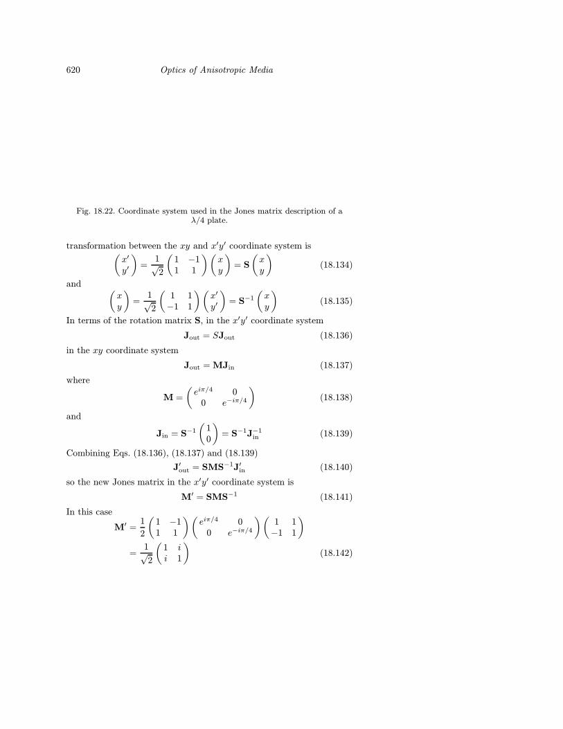
Fig. 18.22. Coordinate system used in the Jones matrix description of aλ/4 plate.
transformation between the xy and x′y′ coordinate system is(x′
y′
)=
1√2
(1 −11 1
)(xy
)= S
(xy
)(18.134)
and (xy
)=
1√2
(1 1−1 1
)(x′
y′
)= S−1
(xy
)(18.135)
In terms of the rotation matrix S, in the x′y′ coordinate system
Jout = SJout (18.136)
in the xy coordinate system
Jout = MJin (18.137)
where
M =
(eiπ/4 0
0 e−iπ/4
)(18.138)
and
Jin = S−1
(10
)= S−1J−1
in (18.139)
Combining Eqs. (18.136), (18.137) and (18.139)
J′out = SMS−1J′in (18.140)
so the new Jones matrix in the x′y′ coordinate system is
M′ = SMS−1 (18.141)
In this case
M′ =1
2
(1 −11 1
)(eiπ/4 0
0 e−iπ/4
)(1 1−1 1
)=
1√2
(1 ii 1
)(18.142)
Problem for Chapter 18 621
We can generalize from this example: if coordinate system x′y′ is ob-
tained by a counterclockwise rotation by angle α from coordinate system
xy, then the transformation matrix is
S =
(cosα sinα− sinα cosα
)(18.143)
The transformation of the Jones matrix from xy to x′y′ obeys Eq.
(18.141).
(e) Faraday Rotator. A Faraday rotator that rotates the plane of linear
polarization in a counterclockwise direction by angle θ has a Jones
matrix
Mfv =
(cos θ − sin θsin θ cos θ
)(18.144)
This brief survey provides the essentials that are needed to describe
the polarization change that occurs in a multi-element optical system.
The one additional matrix method and graphical techniques that can
also be used to provide similar information, in particular the Mueller
Calculus and the Poincare sphere. The interest reader is referred to the
specialized literature.
18.17 Problem for Chapter 18
(1) Prove that in a uniaxial crystal the maximum angular separation of
0- and ε-rays occurs when the wavevector makes an angle θ with the
optic axis that satisfies
θ = arc tan(ne/n0)
REFERENCESR. Clark Jones, “A New Calculus for the Treatment of Optical Systems, I, Desscrip-
tion and Discussion of the Calculus,” J. Opt. Soc. Am., 31, 488-493 (1941); see
also R. Clark Jones, J. Opt. Soc. Am., 31, 493-499 (1941); 31, 500-503 (1941); 32,
486-493 (1942); 37, 107-110 (1942); 38, 671-685 (1948); 46, 126-131 (1956).
D.S. Kliger, J.W. Lewis, and C.E. Randall, Polarized Light in Optics and Spec-
troscopy, Academic Press, San Diego, 1990.
W.A. Sherchoff, Polarized Light: Production and Use, Harvard University Press,
Cambridge, MA, 1962.
Further Reading
R.M.A. Azzam and N.M. Bashara, Ellipsometry and Polarized Light, North-Holland,
Amsterdam, 1977.
E. Wahlstrom, Optical Crystallography, 3rd Edition, Wiley, New York, 1960.
A. Yariv and P. Yeh, Optical Waves in Crystals, Wiley, New York, 1984.