Embed Size (px)
Citation preview
Angelina TM Predesign Charts
27 May 2009Esch-sur-Alzette
R. ZanonO. VassartM. Braun Y.ConanM. Brasseur
Design Charts AngelinaEsch-sur-Alzette - 27 May 2009 1
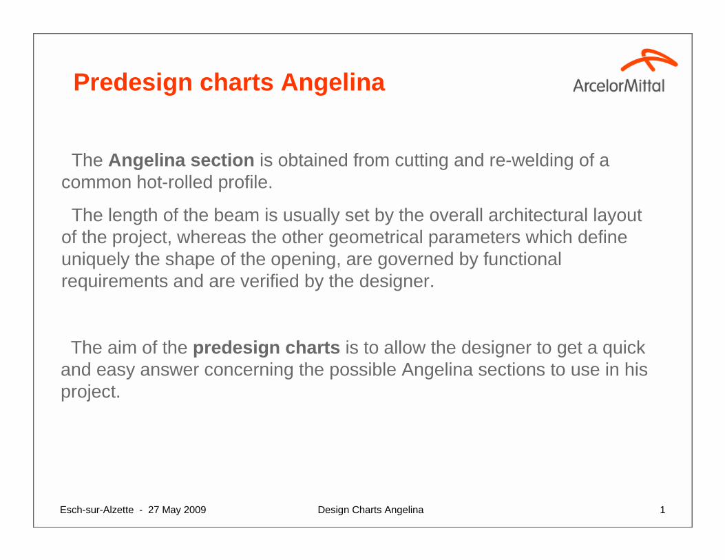
Predesign charts Angelina
The aim of the predesign charts is to allow the designer to get a quick and easy answer concerning the possible Angelina sections to use in hisproject.
The Angelina section is obtained from cutting and re-welding of a common hot-rolled profile.
The length of the beam is usually set by the overall architectural layoutof the project, whereas the other geometrical parameters which defineuniquely the shape of the opening, are governed by functionalrequirements and are verified by the designer.
Design Charts AngelinaEsch-sur-Alzette - 27 May 2009 2
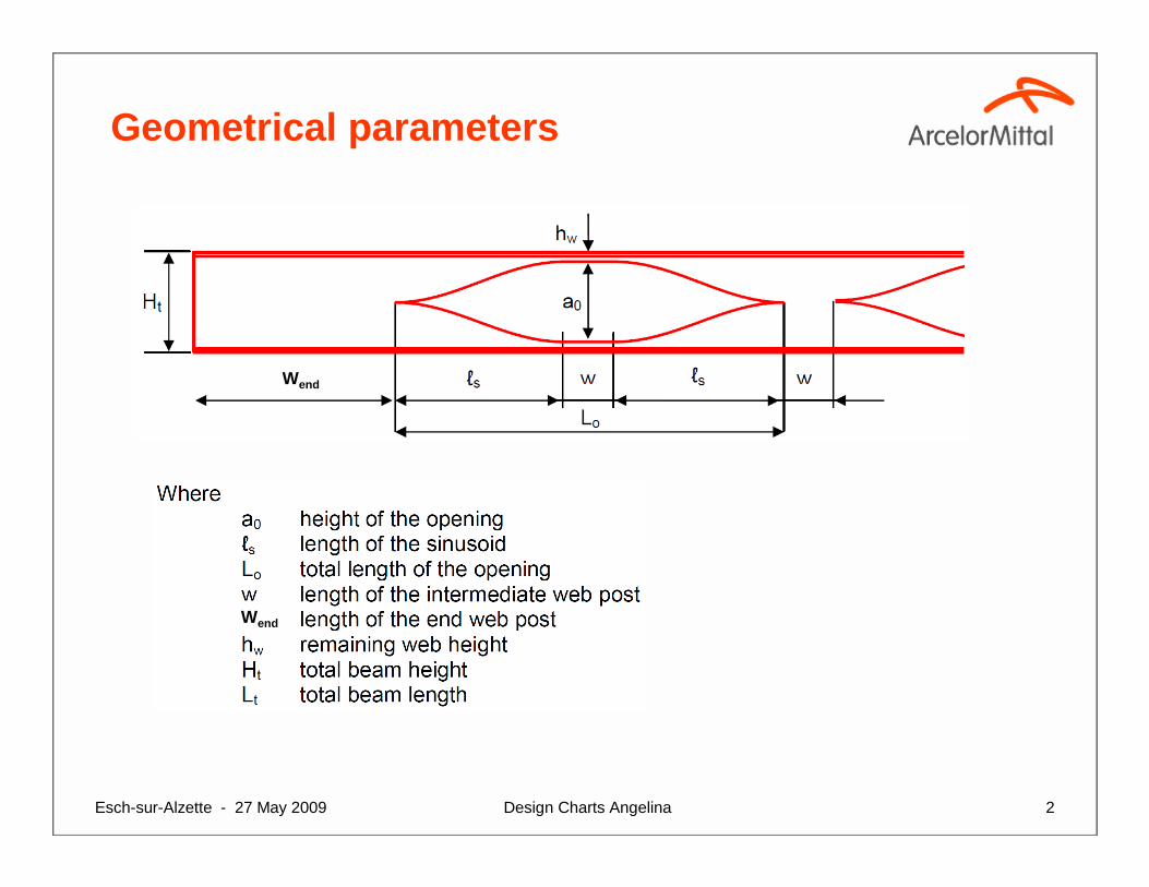
Geometrical parameters
Wend
Wend
Design Charts AngelinaEsch-sur-Alzette - 27 May 2009 3
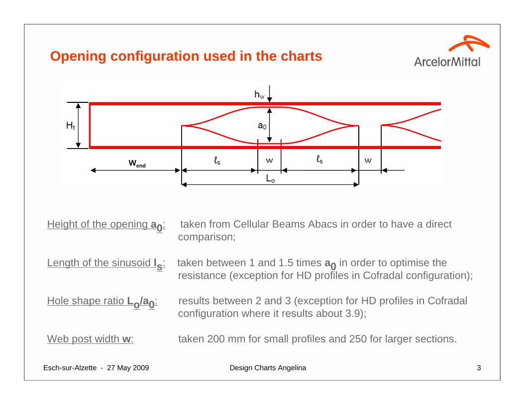
Opening configuration used in the charts
Height of the opening a0: taken from Cellular Beams Abacs in order to have a direct comparison;
Length of the sinusoid ls: taken between 1 and 1.5 times a0 in order to optimise the resistance (exception for HD profiles in Cofradal configuration);
Hole shape ratio Lo/a0: results between 2 and 3 (exception for HD profiles in Cofradalconfiguration where it results about 3.9);
Web post width w: taken 200 mm for small profiles and 250 for larger sections.
Wend
Design Charts AngelinaEsch-sur-Alzette - 27 May 2009 4
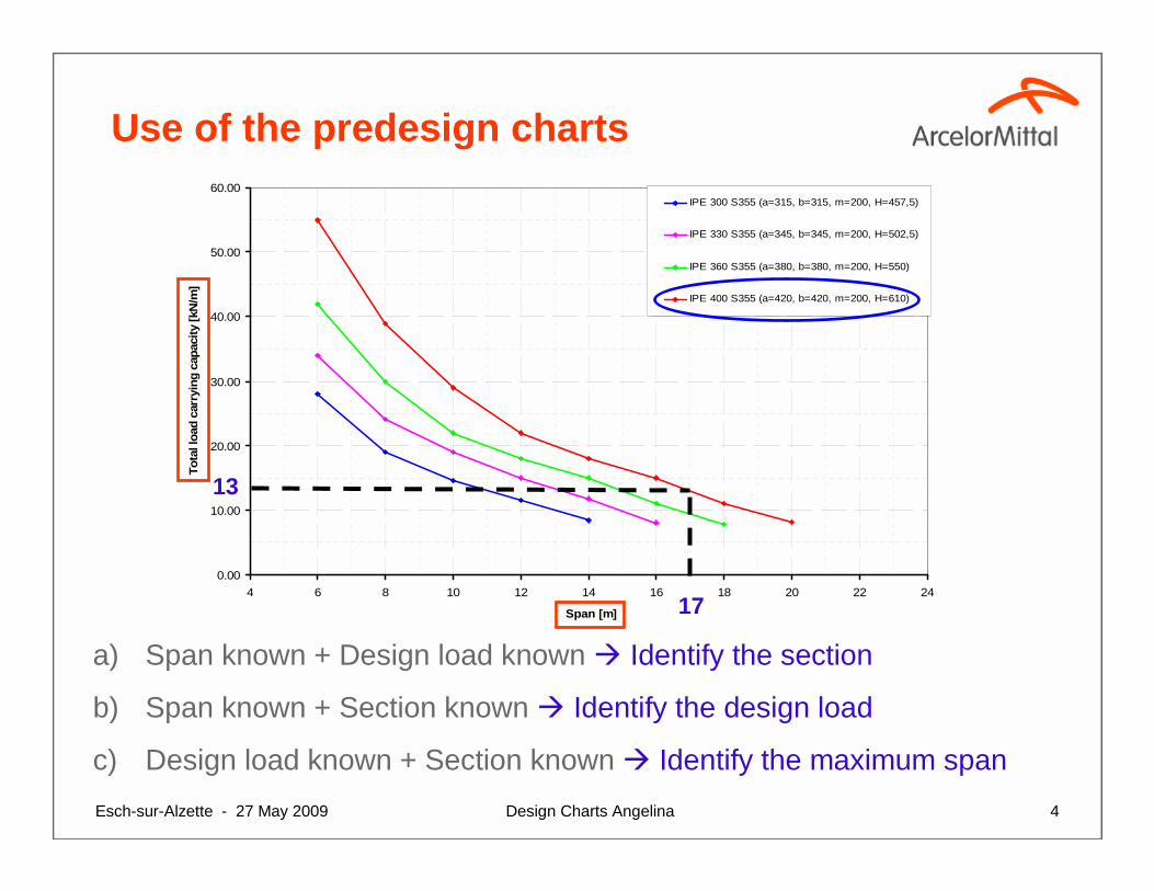
Use of the predesign charts
a) Span known + Design load known � Identify the section
b) Span known + Section known � Identify the design load
c) Design load known + Section known � Identify the maximum span
0.00
10.00
20.00
30.00
40.00
50.00
60.00
4 6 8 10 12 14 16 18 20 22 24
Span [m]
Tot
al lo
ad c
arry
ing
capa
city
[kN
/m]
IPE 300 S355 (a=315, b=315, m=200, H=457,5)
IPE 330 S355 (a=345, b=345, m=200, H=502,5)
IPE 360 S355 (a=380, b=380, m=200, H=550)
IPE 400 S355 (a=420, b=420, m=200, H=610)
17
13
Design Charts AngelinaEsch-sur-Alzette - 27 May 2009 5
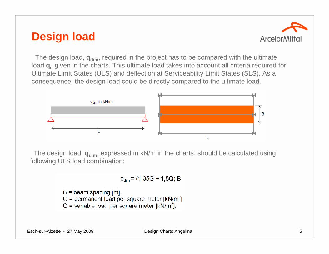
The design load, qdim, required in the project has to be compared with the ultimate load qu given in the charts. This ultimate load takes into account all criteria required for Ultimate Limit States (ULS) and deflection at Serviceability Limit States (SLS). As a consequence, the design load could be directly compared to the ultimate load.
The design load, qdim, expressed in kN/m in the charts, should be calculated using following ULS load combination:
Design load
Design Charts AngelinaEsch-sur-Alzette - 27 May 2009 6
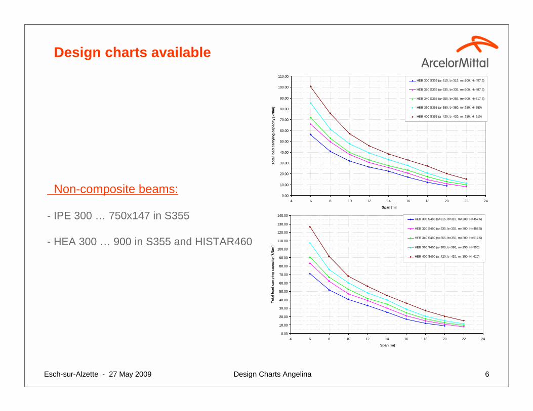
Design charts available
Non-composite beams:
- IPE 300 … 750x147 in S355
- HEA 300 … 900 in S355 and HISTAR460
0.00
10.00
20.00
30.00
40.00
50.00
60.00
70.00
80.00
90.00
100.00
110.00
4 6 8 10 12 14 16 18 20 22 24
Span [m]
Tot
al lo
ad c
arry
ing
capa
city
[kN
/m]
HEB 300 S355 (a=315, b=315, m=200, H=457,5)
HEB 320 S355 (a=335, b=335, m=200, H=487,5)
HEB 340 S355 (a=355, b=355, m=200, H=517,5)
HEB 360 S355 (a=380, b=380, m=250, H=550)
HEB 400 S355 (a=420, b=420, m=250, H=610)
0.00
10.00
20.00
30.00
40.00
50.00
60.00
70.00
80.00
90.00
100.00
110.00
120.00
130.00
140.00
4 6 8 10 12 14 16 18 20 22 24
Span [m]
Tot
al lo
ad c
arry
ing
capa
city
[kN
/m]
HEB 300 S460 (a=315, b=315, m=200, H=457,5)
HEB 320 S460 (a=335, b=335, m=200, H=487,5)
HEB 340 S460 (a=355, b=355, m=200, H=517,5)
HEB 360 S460 (a=380, b=380, m=250, H=550)
HEB 400 S460 (a=420, b=420, m=250, H=610)
Design Charts AngelinaEsch-sur-Alzette - 27 May 2009 7
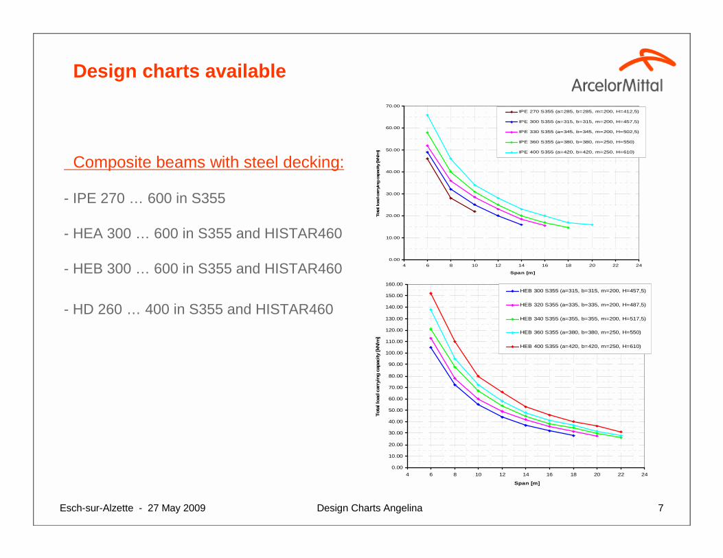
Design charts available
Composite beams with steel decking:
- IPE 270 … 600 in S355
- HEA 300 … 600 in S355 and HISTAR460
- HEB 300 … 600 in S355 and HISTAR460
- HD 260 … 400 in S355 and HISTAR460
0.00
10.00
20.00
30.00
40.00
50.00
60.00
70.00
80.00
90.00
100.00
110.00
120.00
130.00
140.00
150.00
160.00
4 6 8 10 12 14 16 18 20 22 24
Span [m]
Tot
al lo
ad c
arry
ing
capa
city
[kN
/m]
HEB 300 S355 (a=315, b=315, m=200, H=457,5)
HEB 320 S355 (a=335, b=335, m=200, H=487,5)
HEB 340 S355 (a=355, b=355, m=200, H=517,5)
HEB 360 S355 (a=380, b=380, m=250, H=550)
HEB 400 S355 (a=420, b=420, m=250, H=610)
0.00
10.00
20.00
30.00
40.00
50.00
60.00
70.00
4 6 8 10 12 14 16 18 20 22 24
Span [m]
Total lo
ad car
rying
capa
city [k
N/m
]
IPE 270 S355 (a=285, b=285, m=200, H=412,5)
IPE 300 S355 (a=315, b=315, m=200, H=457,5)
IPE 330 S355 (a=345, b=345, m=200, H=502,5)
IPE 360 S355 (a=380, b=380, m=250, H=550)
IPE 400 S355 (a=420, b=420, m=250, H=610)
Design Charts AngelinaEsch-sur-Alzette - 27 May 2009 8
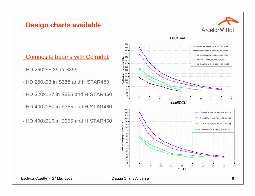
Design charts available
Composite beams with Cofradal:
- HD 260x68.25 in S355
- HD 260x93 in S355 and HISTAR460
- HD 320x127 in S355 and HISTAR460
- HD 400x187 in S355 and HISTAR460
- HD 400x216 in S355 and HISTAR460
HD S355 Cofradal
0
20
40
60
80
100
120
140
160
180
200
220
240
260
280
300
320
4 6 8 10 12 14 16 18 20 22 24
Span [m]
Tota
l loa
d ca
rryi
ng c
apac
ity [k
N/m
]
HD 400x216 (a=440, b=740, m=250, H=595)
HD 400x187 (a=440, b=740, m=250, H=588)
HD 320x127 (a=360, b=580, m=250, H=500)
HD 260x93 (a=250, b=390, m=200, H=385)
HD 260x68.25 (a=250, b=350, m=200, H=375)
HD S460 Cofradal
0
20
40
60
80
100
120
140
160
180
200
220
240
260
280
300
320
340
360
4 6 8 10 12 14 16 18 20 22 24
Span [m]
Tota
l loa
d ca
rryi
ng c
apac
ity [k
N/m
]
HD 400x216 (a=440, b=740, m=250, H=595)
HD 400x187 (a=440, b=740, m=250, H=588)
HD 320x127 (a=360, b=580, m=250, H=500)
HD 260x93 (a=250, b=390, m=200, H=385)
Design Charts AngelinaEsch-sur-Alzette - 27 May 2009 9
Procedure followed to calculate the Predesign Charts
Design Charts AngelinaEsch-sur-Alzette - 27 May 2009 10
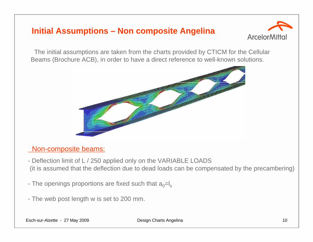
Initial Assumptions – Non composite Angelina
The initial assumptions are taken from the charts provided by CTICM for the Cellular Beams (Brochure ACB), in order to have a direct reference to well-known solutions.
Non-composite beams:
- Deflection limit of L / 250 applied only on the VARIABLE LOADS(it is assumed that the deflection due to dead loads can be compensated by the precambering)
- The openings proportions are fixed such that a0=ls
- The web post length w is set to 200 mm.
Design Charts AngelinaEsch-sur-Alzette - 27 May 2009 11
Initial Assumptions – Composite Angelina3000 mm
180 mm
Steel decking
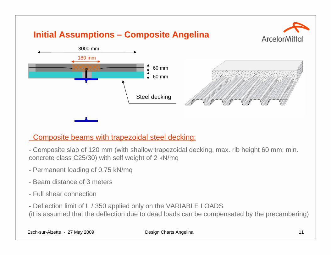
Composite beams with trapezoidal steel decking:
- Composite slab of 120 mm (with shallow trapezoidal decking, max. rib height 60 mm; min. concrete class C25/30) with self weight of 2 kN/mq
- Permanent loading of 0.75 kN/mq
- Beam distance of 3 meters
- Full shear connection
- Deflection limit of L / 350 applied only on the VARIABLE LOADS(it is assumed that the deflection due to dead loads can be compensated by the precambering)
60 mm
60 mm
Design Charts AngelinaEsch-sur-Alzette - 27 May 2009 12
Initial Assumptions – Composite Angelina
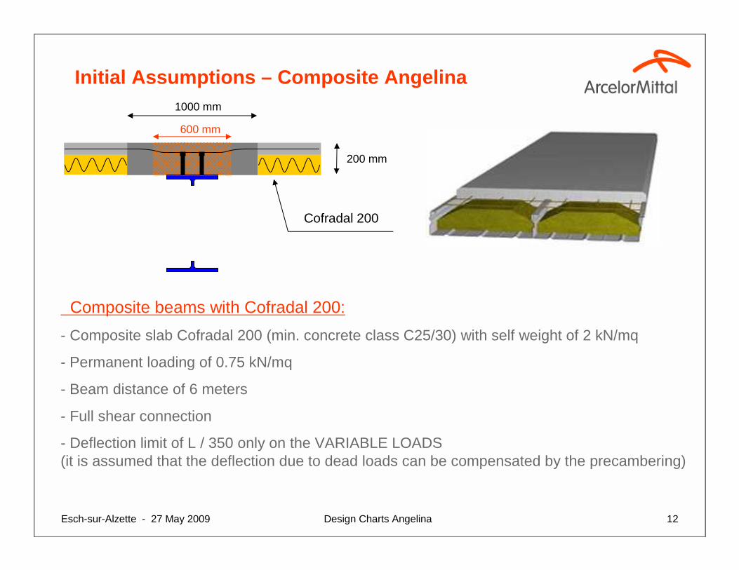
Composite beams with Cofradal 200:
- Composite slab Cofradal 200 (min. concrete class C25/30) with self weight of 2 kN/mq
- Permanent loading of 0.75 kN/mq
- Beam distance of 6 meters
- Full shear connection
- Deflection limit of L / 350 only on the VARIABLE LOADS(it is assumed that the deflection due to dead loads can be compensated by the precambering)
1000 mm
600 mm
Cofradal 200
200 mm
Design Charts AngelinaEsch-sur-Alzette - 27 May 2009 13
Possibility of other Openings configuration
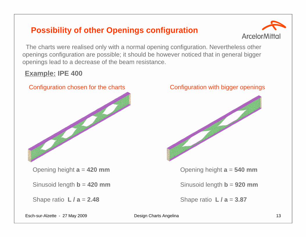
Example: IPE 400
Opening height a = 420 mm
Sinusoid length b = 420 mm
Shape ratio L / a = 2.48
Opening height a = 540 mm
Sinusoid length b = 920 mm
Shape ratio L / a = 3.87
Configuration chosen for the charts Configuration with bigger openings
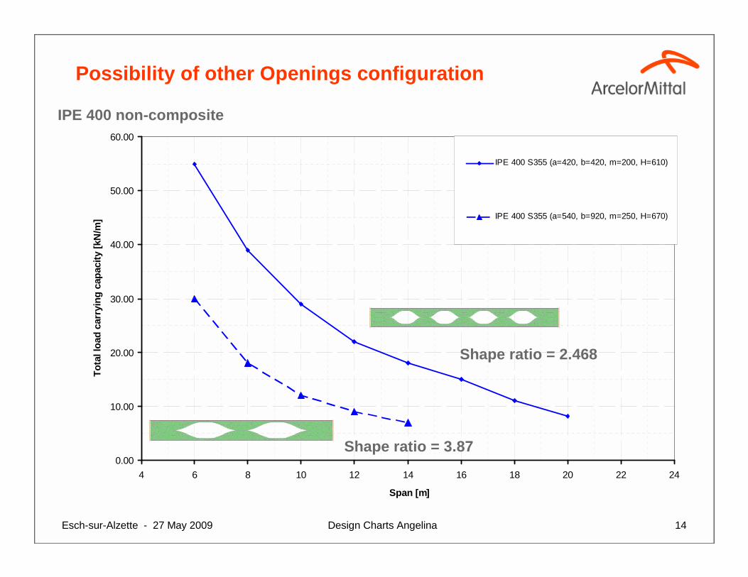
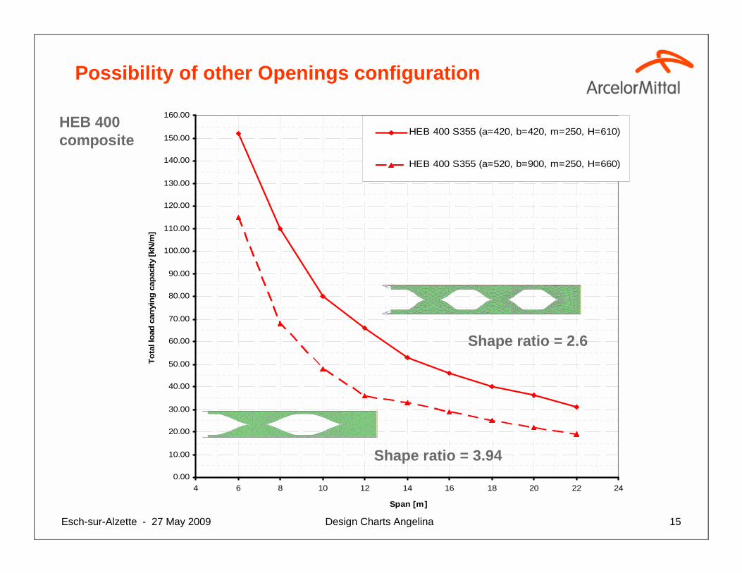
The charts were realised only with a normal opening configuration. Nevertheless otheropenings configuration are possible; it should be however noticed that in general biggeropenings lead to a decrease of the beam resistance.
Design Charts AngelinaEsch-sur-Alzette - 27 May 2009 14
Possibility of other Openings configuration
0.00
10.00
20.00
30.00
40.00
50.00
60.00
4 6 8 10 12 14 16 18 20 22 24
Span [m]
Tot
al lo
ad c
arry
ing
capa
city
[kN
/m]
IPE 400 S355 (a=420, b=420, m=200, H=610)
IPE 400 S355 (a=540, b=920, m=250, H=670)
Shape ratio = 3.87
Shape ratio = 2.468
IPE 400 non-composite
Design Charts AngelinaEsch-sur-Alzette - 27 May 2009 15
0.00
10.00
20.00
30.00
40.00
50.00
60.00
70.00
80.00
90.00
100.00
110.00
120.00
130.00
140.00
150.00
160.00
4 6 8 10 12 14 16 18 20 22 24
Span [m]
Tot
al lo
ad c
arry
ing
capa
city
[kN
/m]
HEB 400 S355 (a=420, b=420, m=250, H=610)
HEB 400 S355 (a=520, b=900, m=250, H=660)
Possibility of other Openings configuration
Shape ratio = 3.94
Shape ratio = 2.6
HEB 400composite
Design Charts AngelinaEsch-sur-Alzette - 27 May 2009 16
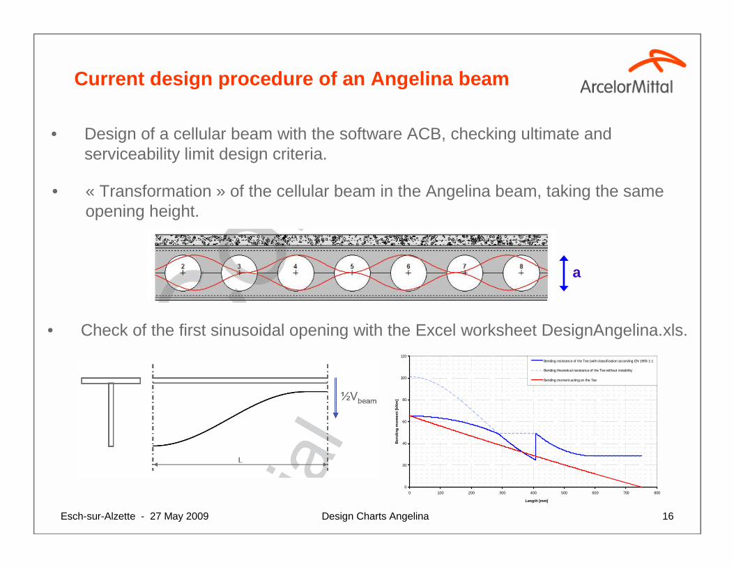
Current design procedure of an Angelina beam
• Design of a cellular beam with the software ACB, checking ultimate and serviceability limit design criteria.
• « Transformation » of the cellular beam in the Angelina beam, taking the sameopening height.
• Check of the first sinusoidal opening with the Excel worksheet DesignAngelina.xls.
0
20
40
60
80
100
120
0 100 200 300 400 500 600 700 800
Length [mm]
Ben
ding
mom
ent [
kNm
]
Bending resistance of the Tee (with classification according EN 1993-1-1
Bending theoretical resistance of the Tee without instability
Bending moment acting on the Tee
a
Design Charts AngelinaEsch-sur-Alzette - 27 May 2009 17
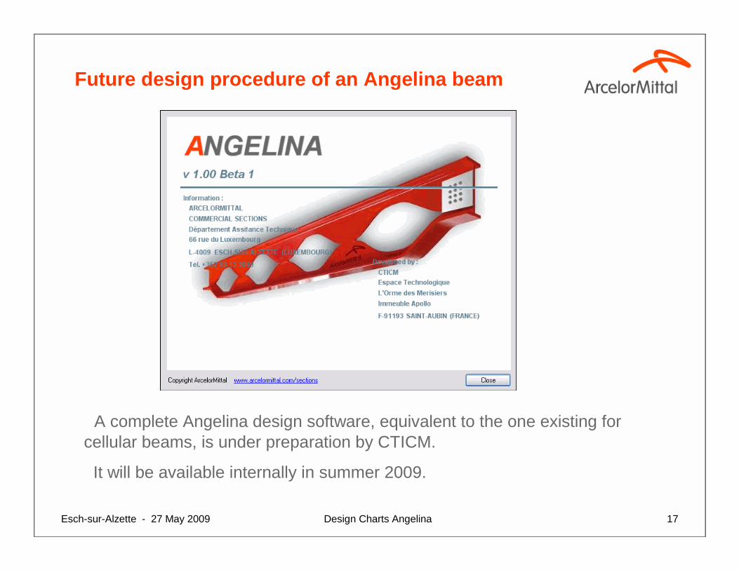
Future design procedure of an Angelina beam
A complete Angelina design software, equivalent to the one existing for cellular beams, is under preparation by CTICM.
It will be available internally in summer 2009.
Design Charts AngelinaEsch-sur-Alzette - 27 May 2009 18
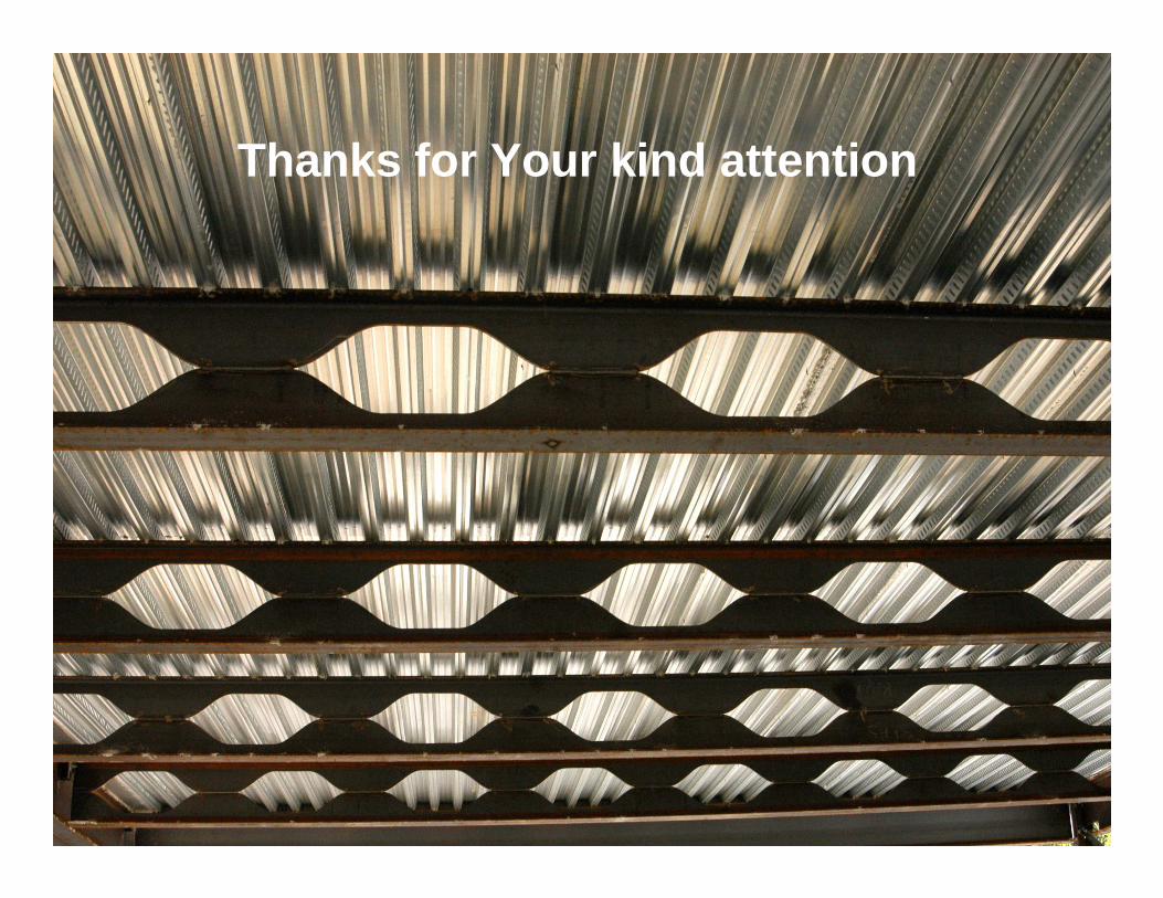
Thanks for Your kind attention


![HIGH-RISE PREDESIGN CONFERENCE Date: [ 12/09/2019 ]](https://img.pdfslide.us/doc/110x75/61ff37f13987432bcd0f6fd8/high-rise-predesign-conference-date-12092019-.jpg)