Embed Size (px)
Citation preview
Mechanics & Industry 21, 604 (2020)© AFM, EDP Sciences 2020https://doi.org/10.1051/meca/2020076
Mechanics&IndustryAvailable online at:
www.mechanics-industry.org
REGULAR ARTICLE
Predesign of a flexible multibody system excited by movingload using a mechatronic system approachGhazoi Hamza1,2,*, Maher Barkallah1, Moncef Hammadi2, Jean-Yves Choley2, Alain Riviere2,Jamel Louati1, and Mohamed Haddar1
1 Mechanics Modeling and Production Research Laboratory (LA2MP), National School of Engineers of Sfax (ENIS),University of Sfax, B.P, 1173, 3038 Sfax, Tunisia
2 QUARTZ EA 7393, SUPMECA, 3 rue Fernand Hainaut, 93407 Saint-Ouen Cedex, France
* e-mail: h
Received: 24 April 2018 / Accepted: 25 August 2020
Abstract. In this paper, a new analytical approach to object oriented modeling is presented for the predesign ofa multibody system. We investigate the dynamic behavior of a system of interconnected components using themodeling language Modelica. In engineering, beam-masses are often used as design models. In fact, theconsidered system is composed of a flexible beam subjected to a moving load and supporting one or moretranslating elastic subsystems. Each subsystem is controlled by a vibration absorber and the structure is affecteddynamically only through the moving character of the load. The problem of calculation of the dynamic responseof this system is very important in many engineering applications such as in the predesign and analysis ofa robotic portal systems, machine tools and bridge crane systems. The object oriented modeling approach will bepresented to demonstrate the importance of this approach to parametric investigation. It will illustrate howsubsystems from Modelica Standard Library can be connected to the developed structure in order to study thevibrational behavior of such a system. For validation purpose, results are compared with those reported in theliterature.
Keywords: Predesign / flexible multibody system / analytical approach / vibration
1 Introduction
Multibody dynamic analysis represents a powerful tool toinvestigate the dynamic response of flexible systems ofarbitrary complexity and topology [1,2]. The multibodysystem modeling is a common approach for representingmechanical systems as interconnected components [3,4].In fact, a flexible multibody system can be composed ofelastic and rigid components which are connected by forceand/or joints elements as springs, dampers, and actuators[5,6]. Alessandro et al. [7] propose two new Modelicalibraries which are the Engines libraries and the PowertrainDynamics (PTDynamics). The libraries enable the model-ing and the simulation of a multibody system in onesimulation environment (Dymola) based on Modelicalanguage. Indeed, Modelica is very appropriate for buildingmuli-domain models [8]. Indeed, Modelica contains manylibraries which help the user in constructing multi-domainmodels.
The skeleton of a mechatronic system is themechanical part. Mechanical systems may be conceptu-alized as elastic and/or rigid bodies. Schneider et al. [9]studied the dynamic and static behavior of a 5-Axis-Milling Machine. The mechanical model of the machine isimplemented in Modelica with rigid and flexible bodies.In fact, using the object oriented modeling approach;a mathematic representation of a physical model may bestructured to get a reusable model that is easy tounderstand and to modify.
In the predesign phase, investigating the physicalinteractions between the diverse subcomponents ofa mechatronic system is of great importance [10]. At thisstage, a preliminary description of a mechanical system isessential for different constraints such as vibration, tem-perature, etc. Each physical phenomenon can be describedby a mathematical model. Thus, a mechanical systemmodeling and simulation which may be based on numerousmathematical models play an important role in order tounderstand how the properties and the performances ofthe mechanical components and subsystems have aneffect on the overall mechatronic system design [11–13].
Fig. 1. The beam model subjected to a moving load.
2 G. Hamza et al.: Mechanics & Industry 21, 604 (2020)
The presence of vibrations is one of themain causes thatlimit performance in mechanical systems. The study of thedynamic behavior is having a great importance in the fieldof mechanical, aerospace engineering and civil [14–17].For instance, in the field of engineering, a variety ofstructure is subjected to moving load. External forces,masses or whole subsystems moving with constant orvarying speed along the structure can be the cause of theseloads. Bridges, cranes and railway track are some cases ofstructures subjected to dynamic load. The study of thestructure’s reaction to these moving loads is very essential.Moreover, the dynamic of flexible structures with movingloads have been the subjects of many studies. For example,Zrnic et al. [18] studied the impact of a moving load todynamic behavior of container cranes. The dynamicinteraction between the supporting structure and thetrolley caused by the moving load is also investigated.
There are many engineering problems can be modeledas the coupled structure-simple degree of freedom (SDOF)system, such as a motor, engine and electronic cardelastically mounted on a structural element. For instance,Hamza et al. [19] proposed a predesign method applied toamechatronic system in order to study its vibrational effect.The interaction between different subsystems (motors andelectronics cards) located on a simply supported plate hasbeen investigated.The electronic card ismodeled as a simpledegree of freedom system attached to the main structure(the plate) and the motor is modeled as a dynamicexcitation over a finite area on the plate.
Vibration control is very important in order to reducestructural vibrations. Structural control systems areclassified into two main categories which are passive andactive control system. Dynamic vibration absorber (DVA)is one of the techniques used in vibration control. It consistsof attaching a secondary mass to a primary vibratingsystem such that the secondary mass dissipates the energyof the primary system and reduces its vibration amplitude.
When machinery systems are subjected to vibrationsdue to external disturbances, vibration absorbers havebeen used widely for vibration reduction. Lin and Cho [20]proposed the application of a DVA in order to reduce theexcessive vibration of a simply supported beam traversedby multiple moving loads. Soares et al. [21] studied thedynamic response of an Euler-Bernoulli beam subjected tomoving loads and controlled by a moving vibrationabsorber. The vibration absorber is modeled as a linearspring-mass-damper system moving with a constant speedalong the beam. The importance of speed and position ofthe damper on the vibration control of the beam subjectedto moving loads is shown in this paper. To suppress theexcessive vibration of a beam under a moving load, Sung[22] employed piezoelectric actuators that are bonded atthe bottom of the beam at different positions.
The dynamic vibration absorber is probably the mostcommon device for passive vibration of machines. It can bealso called tuned mass damper (TMD). Because it is simpleand robust, it has been used in many applications such asmechanical, civil and aerospace engineering. For instance,Chaari [23] proposed a passive vibration absorber model inorder to decrease the vibration amplitude of a milling tool.Samani et al. [24] studied the performances of different
types of dynamic vibration absorbers. A (DVA) isconnected to a simply supported beam in order to reducethe excessive vibrations. The beam is traversed by movingloads/vehicles. The vehicle is modeled by a single degree offreedom mass spring system. To find the optimalparameters of the DVA that minimize the beam vibration,a parametric analysis is performed.
In the present study, a new mechatronic-basedapproach to model and simulate a multibody system ispresented. We study the structure interacting throughmoving load using Modelica language. The beam structurecarried one or more subsystems which are modeled assimple degree of freedom systems. The excessive vibrationof the subsystem is controlled using a dynamic vibrationabsorber. The paper is organized as follows: the governingequations of a flexible beam and a connected subsystemwillbe derived in Section 2. Section 3 presents the methodologyfor modeling and control design of such multibody system.Numerical examples of the proposed methodology appearin Section 4. Section 5 concludes the paper.
2 Multibody formulation
The theoretical background of multibody systems isdescribed in this section. The equations of motion areexpressed as differential-algebraic equations (DAE).
2.1 Model formulation of the beam vibration
The system under consideration is shown in Figure 1.Consider a moving mass rolling on a finite simplysupported beam at a specified speed. The Euler-Bernoullibeam theory is used, ignoring shear deformation effects.The beam is considered as a linear elastic continuous system.The effect ofdampingwasconsiderednegligible.TheFourierapproach used in [25] will be adopted in our study.
The equation of motion for an Euler-Bernoulli beamunder a general forcing function can be written as [25]:
EI∂4uðx; tÞ
∂x4þ rS þMd x� vtð Þ½ � ∂
2u x; tð Þ∂t2
¼ gMd x� vtð Þ:ð1Þ
In equation (1), u is the displacement of beam in they direction, S is the cross-sectional area, l is the beamlength,EI is the bending stiffness, t is the time, r is themassdensity, M is the mass of the moving load and v is the loadspeed over the beam.
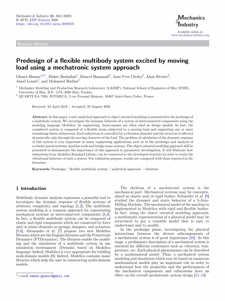
Fig. 2. Subsystem parameters.
G. Hamza et al.: Mechanics & Industry 21, 604 (2020) 3
d (x� vt) is the Dirac Delta function
d x� vtð Þ ¼ 0 ਡfor ਡx≠ vt: ð2ÞThe boundary conditions of a simply supported beam
could be defined as:
u 0ð Þ ¼ 0;d2u
dx20ð Þ ¼ 0;u lð Þ ¼ 0;
d2u
dx2lð Þ ¼ 0; ð3Þ
The initial conditions of the problem are given by,
uðx; 0Þ ¼ 0;∂u∂t
x; 0ð Þ ¼ 0: ð4Þ
The beam is simply supported at both ends; theEigenfrequency for nth mode is given by:
vi ¼ i2p2
l2
ffiffiffiffiffiffiffiEI
rA
s: ð5Þ
In addition,
Z l
0
d x� vtð Þdx ¼ 1: ð6Þ
Applying the Fourier finite sine transform,
Fðm; tÞ ¼Z l
0
uðx; tÞ sinmpx
ldx: ð7Þ
The transformed equation of the problem is [25],
Ftt m; tð Þ þ v2mF m; tð Þ þ 1
rSLM
� Fttðm; tÞ þ 2X∞k¼1
Ftt k; tð Þ sin kpvtl
sinmpvt
l
" #
¼ g
rSM sin
mpvt
l: ð8Þ
We consider only the linear inertia term, equation (8)becomes [25]:
Ftt m; tð Þ þ v2m
1þRð ÞF m; tð Þ ¼ P
1þRð Þ sinmpvt
l: ð9Þ
With,
R ¼ M
rSl: ð10Þ
Then,
F m; tð Þ ¼ p
v2m 1� mpv
ffiffiffiffiffiffiffiffiffiffiffiffi1þR
p
lvm
� �2" #
� sinmpvt
l�mpv
ffiffiffiffiffiffiffiffiffiffiffiffiffiffiffiffi1þRð Þp
lvmsin
vmtffiffiffiffiffiffiffiffiffiffiffiffiffiffiffiffi1þRð Þp
" #: ð11Þ
Defining,
P ¼ Mg
rS: ð12Þ
The expression of the beam displacement u(x, t) can beassumed as [25]:
uðx; tÞ ¼ 2P
l
X∞m¼1
sinmpvt
l�mpv
ffiffiffiffiffiffiffiffiffiffiffiffi1þR
p
lvmsin
vmffiffiffiffiffiffiffiffiffiffiffiffiffiffiffiffi1þRð Þp t
" #
v2m 1� mpv
ffiffiffiffiffiffiffiffiffiffiffiffiffiffiffiffið1þRÞpLvm
!20@
1A
sinmpx
l: ð13Þ
2.2 Modeling of the connected subsystem
This section shows the dynamic behavior of a subsystemattached to the flexible beam. It is modeled as an oscillatormodel (a single degree of freedom mass spring system) oncontact with the beam. The connected subsystem vibratesas a result of the oscillation of the support structure.The body mass is small compared to the beam mass, theeffect of the beam on the subsystem in only taken intoaccount. Figure 2 shows a simple representation of thesubsystem model.
The balance equation of the subsystem is:
€Z þ 2sj _Z þ s2Z ¼ �€Y ð14ÞZ is the relative displacement of the subsystemwith respectto the beam.
With,
Z ¼ X � Y ð15Þwhere _Z and Z are respectively, the relative velocity andacceleration of the subsystem. X is the absolute displace-ment of the subsystem and Y is the base inputdisplacement.
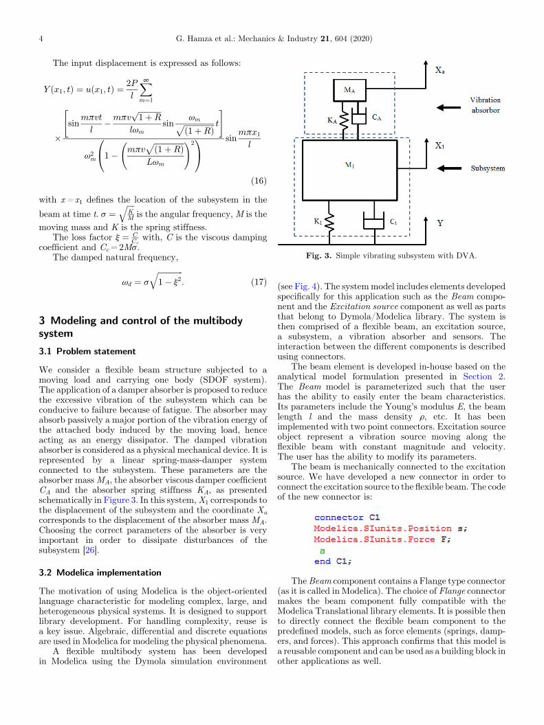
Fig. 3. Simple vibrating subsystem with DVA.
4 G. Hamza et al.: Mechanics & Industry 21, 604 (2020)
The input displacement is expressed as follows:
Y ðx1; tÞ ¼ uðx1; tÞ ¼ 2P
l
X∞m¼1
�sin
mpvt
l�mpv
ffiffiffiffiffiffiffiffiffiffiffiffi1þR
p
lvmsin
vmffiffiffiffiffiffiffiffiffiffiffiffiffiffiffiffi1þRð Þp t
" #
v2m 1� mpv
ffiffiffiffiffiffiffiffiffiffiffiffiffiffiffiffið1þRÞpLvm
!20@
1A
sinmpx1
l
ð16Þwith x=x1 defines the location of the subsystem in the
beam at time t. s ¼ffiffiffiffiKM
qis the angular frequency, M is the
moving mass and K is the spring stiffness.The loss factor j ¼ C
Ccwith, C is the viscous damping
coefficient and Cc=2Ms.The damped natural frequency,
vd ¼ s
ffiffiffiffiffiffiffiffiffiffiffiffiffi1� j2
q: ð17Þ
3 Modeling and control of the multibodysystem
3.1 Problem statement
We consider a flexible beam structure subjected to amoving load and carrying one body (SDOF system).The application of a damper absorber is proposed to reducethe excessive vibration of the subsystem which can beconducive to failure because of fatigue. The absorber mayabsorb passively a major portion of the vibration energy ofthe attached body induced by the moving load, henceacting as an energy dissipator. The damped vibrationabsorber is considered as a physical mechanical device. It isrepresented by a linear spring-mass-damper systemconnected to the subsystem. These parameters are theabsorber massMA, the absorber viscous damper coefficientCA and the absorber spring stiffness KA, as presentedschematically in Figure 3. In this system,X1 corresponds tothe displacement of the subsystem and the coordinate Xacorresponds to the displacement of the absorber mass MA.Choosing the correct parameters of the absorber is veryimportant in order to dissipate disturbances of thesubsystem [26].
3.2 Modelica implementation
The motivation of using Modelica is the object-orientedlanguage characteristic for modeling complex, large, andheterogeneous physical systems. It is designed to supportlibrary development. For handling complexity, reuse isa key issue. Algebraic, differential and discrete equationsare used in Modelica for modeling the physical phenomena.
A flexible multibody system has been developedin Modelica using the Dymola simulation environment
(see Fig. 4). The systemmodel includes elements developedspecifically for this application such as the Beam compo-nent and the Excitation source component as well as partsthat belong to Dymola/Modelica library. The system isthen comprised of a flexible beam, an excitation source,a subsystem, a vibration absorber and sensors. Theinteraction between the different components is describedusing connectors.
The beam element is developed in-house based on theanalytical model formulation presented in Section 2.The Beam model is parameterized such that the userhas the ability to easily enter the beam characteristics.Its parameters include the Young’s modulus E, the beamlength l and the mass density r, etc. It has beenimplemented with two point connectors. Excitation sourceobject represent a vibration source moving along theflexible beam with constant magnitude and velocity.The user has the ability to modify its parameters.
The beam is mechanically connected to the excitationsource. We have developed a new connector in order toconnect the excitation source to the flexible beam. The codeof the new connector is:
TheBeam component contains a Flange type connector(as it is called in Modelica). The choice of Flange connectormakes the beam component fully compatible with theModelica Translational library elements. It is possible thento directly connect the flexible beam component to thepredefined models, such as force elements (springs, damp-ers, and forces). This approach confirms that this model isa reusable component and can be used as a building block inother applications as well.
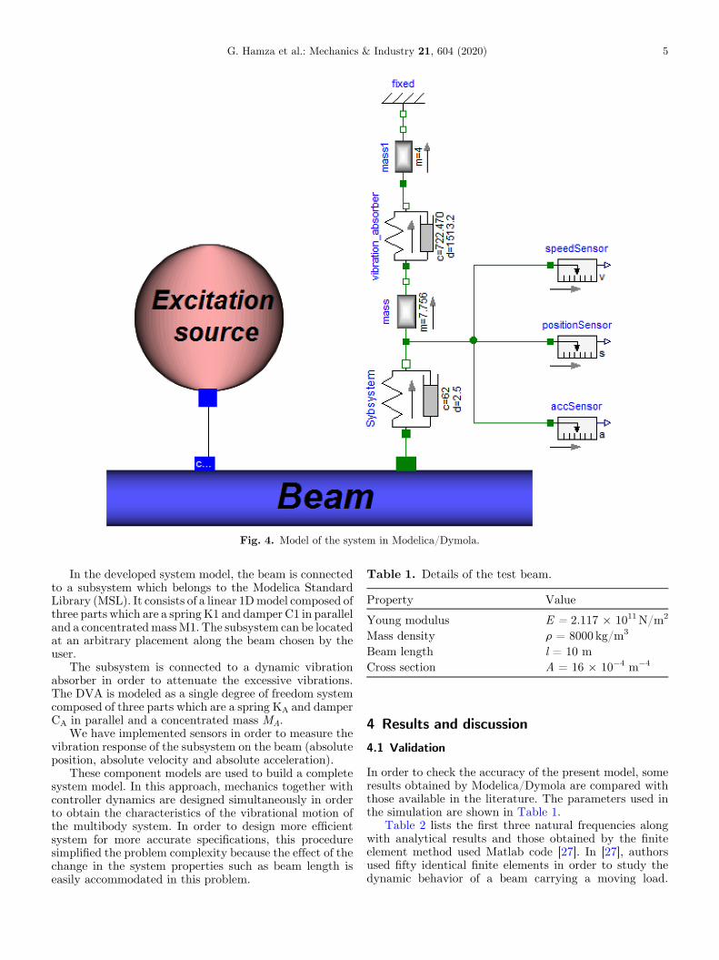
Fig. 4. Model of the system in Modelica/Dymola.
Table 1. Details of the test beam.
Property Value
Young modulus E = 2.117 � 1011N/m2
Mass density r = 8000 kg/m3
Beam length l = 10 mCross section A = 16 � 10�4 m�4
G. Hamza et al.: Mechanics & Industry 21, 604 (2020) 5
In the developed system model, the beam is connectedto a subsystem which belongs to the Modelica StandardLibrary (MSL). It consists of a linear 1Dmodel composed ofthree parts which are a spring K1 and damper C1 in paralleland a concentratedmassM1. The subsystem can be locatedat an arbitrary placement along the beam chosen by theuser.
The subsystem is connected to a dynamic vibrationabsorber in order to attenuate the excessive vibrations.The DVA is modeled as a single degree of freedom systemcomposed of three parts which are a spring KA and damperCA in parallel and a concentrated mass MA.
We have implemented sensors in order to measure thevibration response of the subsystem on the beam (absoluteposition, absolute velocity and absolute acceleration).
These component models are used to build a completesystem model. In this approach, mechanics together withcontroller dynamics are designed simultaneously in orderto obtain the characteristics of the vibrational motion ofthe multibody system. In order to design more efficientsystem for more accurate specifications, this proceduresimplified the problem complexity because the effect of thechange in the system properties such as beam length iseasily accommodated in this problem.
4 Results and discussion
4.1 Validation
In order to check the accuracy of the present model, someresults obtained by Modelica/Dymola are compared withthose available in the literature. The parameters used inthe simulation are shown in Table 1.
Table 2 lists the first three natural frequencies alongwith analytical results and those obtained by the finiteelement method used Matlab code [27]. In [27], authorsused fifty identical finite elements in order to study thedynamic behavior of a beam carrying a moving load.
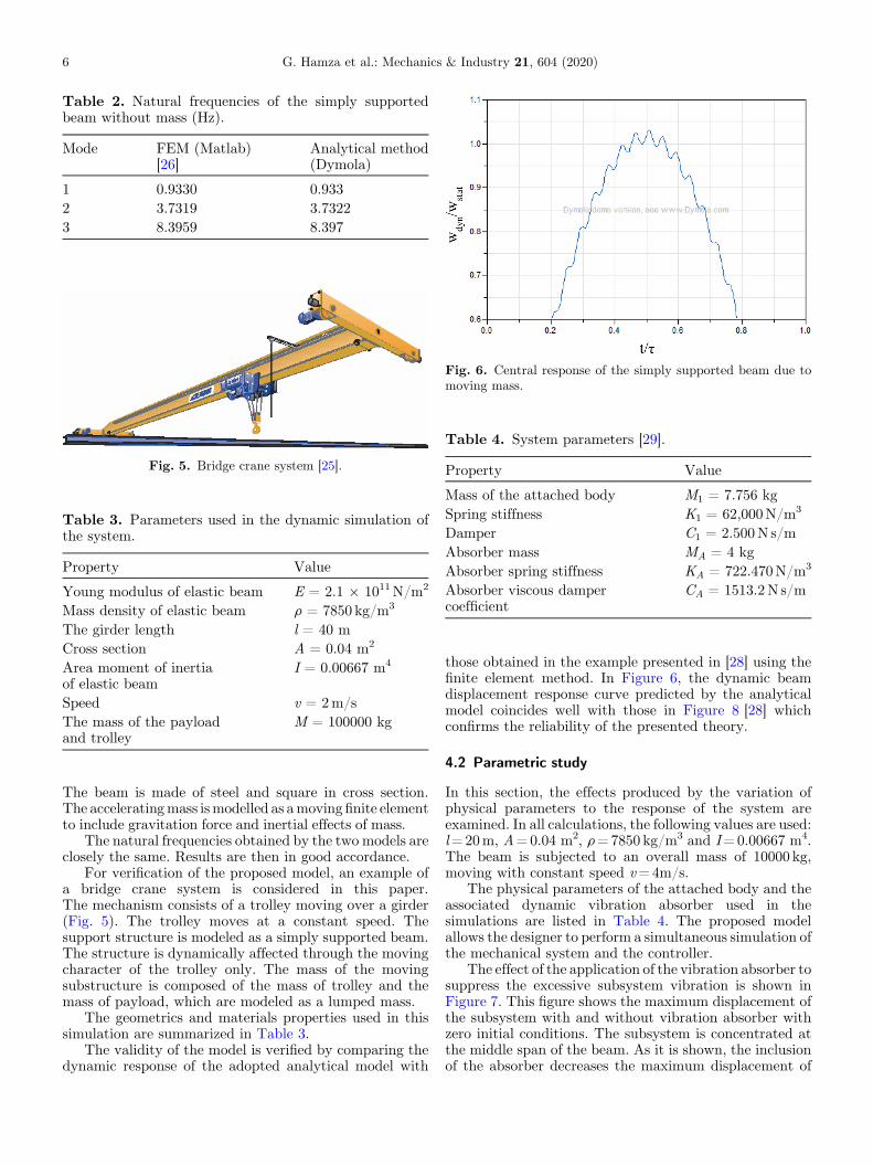
Table 3. Parameters used in the dynamic simulation ofthe system.
Property Value
Young modulus of elastic beam E = 2.1 � 1011N/m2
Mass density of elastic beam r = 7850 kg/m3
The girder length l = 40 mCross section A = 0.04 m2
Area moment of inertiaof elastic beam
I = 0.00667 m4
Speed v = 2m/sThe mass of the payloadand trolley
M = 100000 kg
Table 4. System parameters [29].
Property Value
Mass of the attached body M1 = 7.756 kgSpring stiffness K1 = 62,000N/m3
Damper C1 = 2.500N s/mAbsorber mass MA = 4 kgAbsorber spring stiffness KA = 722.470N/m3
Absorber viscous dampercoefficient
CA = 1513.2N s/m
Table 2. Natural frequencies of the simply supportedbeam without mass (Hz).
Mode FEM (Matlab)[26]
Analytical method(Dymola)
1 0.9330 0.9332 3.7319 3.73223 8.3959 8.397
Fig. 5. Bridge crane system [25].
Fig. 6. Central response of the simply supported beam due tomoving mass.
6 G. Hamza et al.: Mechanics & Industry 21, 604 (2020)
The beam is made of steel and square in cross section.The acceleratingmass ismodelled as amovingfinite elementto include gravitation force and inertial effects of mass.
The natural frequencies obtained by the two models areclosely the same. Results are then in good accordance.
For verification of the proposed model, an example ofa bridge crane system is considered in this paper.The mechanism consists of a trolley moving over a girder(Fig. 5). The trolley moves at a constant speed. Thesupport structure is modeled as a simply supported beam.The structure is dynamically affected through the movingcharacter of the trolley only. The mass of the movingsubstructure is composed of the mass of trolley and themass of payload, which are modeled as a lumped mass.
The geometrics and materials properties used in thissimulation are summarized in Table 3.
The validity of the model is verified by comparing thedynamic response of the adopted analytical model with
those obtained in the example presented in [28] using thefinite element method. In Figure 6, the dynamic beamdisplacement response curve predicted by the analyticalmodel coincides well with those in Figure 8 [28] whichconfirms the reliability of the presented theory.
4.2 Parametric study
In this section, the effects produced by the variation ofphysical parameters to the response of the system areexamined. In all calculations, the following values are used:l=20m, A=0.04 m2, r=7850 kg/m3 and I=0.00667 m4.The beam is subjected to an overall mass of 10000 kg,moving with constant speed v=4m/s.
The physical parameters of the attached body and theassociated dynamic vibration absorber used in thesimulations are listed in Table 4. The proposed modelallows the designer to perform a simultaneous simulation ofthe mechanical system and the controller.
The effect of the application of the vibration absorber tosuppress the excessive subsystem vibration is shown inFigure 7. This figure shows the maximum displacement ofthe subsystem with and without vibration absorber withzero initial conditions. The subsystem is concentrated atthe middle span of the beam. As it is shown, the inclusionof the absorber decreases the maximum displacement of
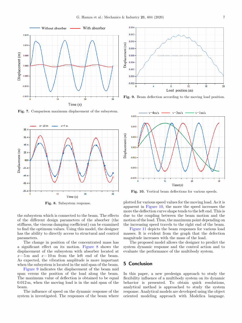
Fig. 7. Comparison maximum displacement of the subsystem.
Fig. 8. Subsystem response.
Fig. 9. Beam deflection according to the moving load position.
Fig. 10. Vertical beam deflections for various speeds.
G. Hamza et al.: Mechanics & Industry 21, 604 (2020) 7
the subsystem which is connected to the beam. The effectsof the different design parameters of the absorber (thestiffness, the viscous damping coefficient) can be examinedto find the optimum values. Using this model, the designerhas the ability to directly access to structural and controlparameters.
The change in position of the concentrated mass hasa significant effect on its motion. Figure 8 shows thedisplacement of the subsystem with absorber located atx=5m and x=10m from the left end of the beam.As expected, the vibration amplitude is more importantwhen the subsystem is located in the mid span of the beam.
Figure 9 indicates the displacement of the beam midspan versus the position of the load along the beam.The maximum value of deflection is obtained to be equal0.012m, when the moving load is in the mid span of thebeam.
The influence of speed on the dynamic response of thesystem is investigated. The responses of the beam where
plotted for various speed values for the moving load. As it isapparent in Figure 10, the more the speed increases themore the deflection curve shape tends to the left end. This isdue to the coupling between the beam motion and themotion of the load. Thus, themaximumpoint depending onthe increasing speed travels to the right end of the beam.
Figure 11 depicts the beam responses for various loadmasses. It is evident from the graph that the defectionmagnitude increases with the mass of the load.
The proposed model allows the designer to predict thesystem dynamic response and the control action and toevaluate the performance of the multibody system.
5 Conclusion
In this paper, a new predesign approach to study theflexibility influence of a multibody system on its dynamicbehavior is presented. To obtain quick resolutions,analytical method is approached to study the systemresponse. Analytical models are developed using the objectoriented modeling approach with Modelica language.
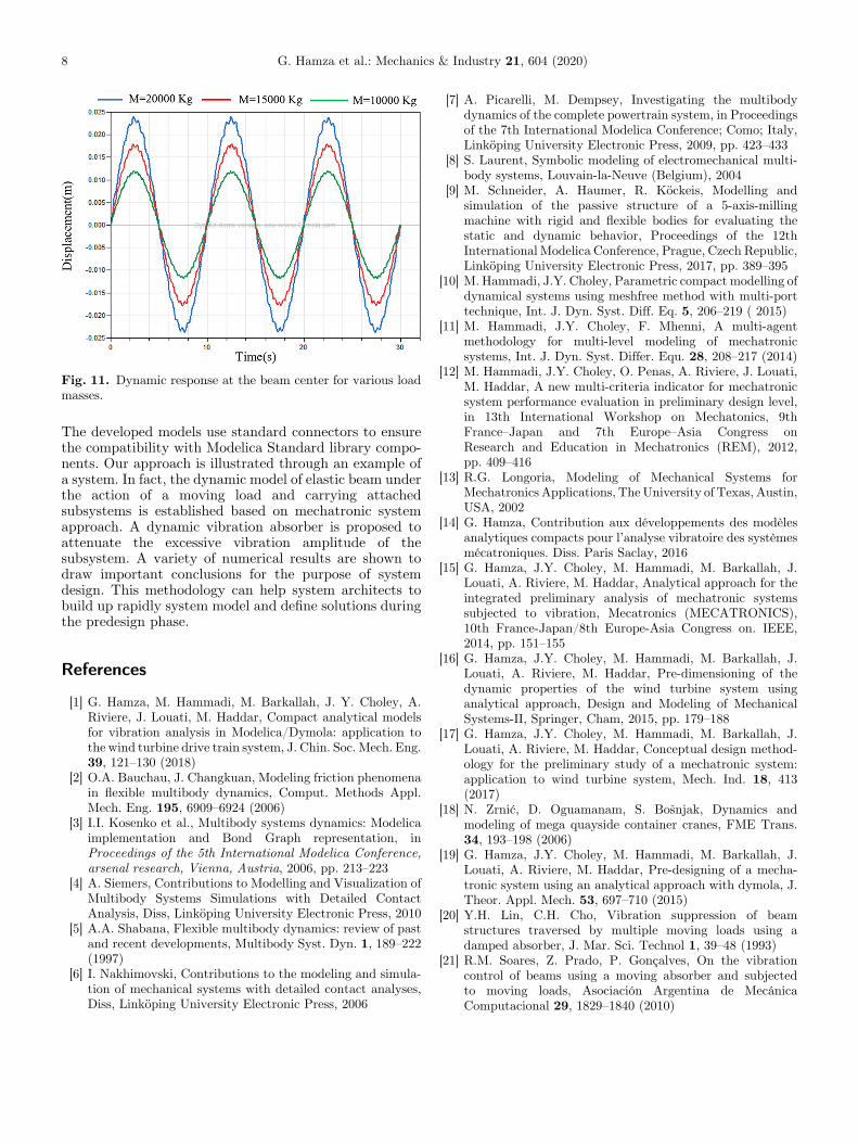
Fig. 11. Dynamic response at the beam center for various loadmasses.
8 G. Hamza et al.: Mechanics & Industry 21, 604 (2020)
The developed models use standard connectors to ensurethe compatibility with Modelica Standard library compo-nents. Our approach is illustrated through an example ofa system. In fact, the dynamic model of elastic beam underthe action of a moving load and carrying attachedsubsystems is established based on mechatronic systemapproach. A dynamic vibration absorber is proposed toattenuate the excessive vibration amplitude of thesubsystem. A variety of numerical results are shown todraw important conclusions for the purpose of systemdesign. This methodology can help system architects tobuild up rapidly system model and define solutions duringthe predesign phase.
References
[1] G. Hamza, M. Hammadi, M. Barkallah, J. Y. Choley, A.Riviere, J. Louati, M. Haddar, Compact analytical modelsfor vibration analysis in Modelica/Dymola: application tothe wind turbine drive train system, J. Chin. Soc. Mech. Eng.39, 121–130 (2018)
[2] O.A. Bauchau, J. Changkuan, Modeling friction phenomenain flexible multibody dynamics, Comput. Methods Appl.Mech. Eng. 195, 6909–6924 (2006)
[3] I.I. Kosenko et al., Multibody systems dynamics: Modelicaimplementation and Bond Graph representation, inProceedings of the 5th International Modelica Conference,arsenal research, Vienna, Austria, 2006, pp. 213–223
[4] A. Siemers, Contributions to Modelling and Visualization ofMultibody Systems Simulations with Detailed ContactAnalysis, Diss, Linköping University Electronic Press, 2010
[5] A.A. Shabana, Flexible multibody dynamics: review of pastand recent developments, Multibody Syst. Dyn. 1, 189–222(1997)
[6] I. Nakhimovski, Contributions to the modeling and simula-tion of mechanical systems with detailed contact analyses,Diss, Linköping University Electronic Press, 2006
[7] A. Picarelli, M. Dempsey, Investigating the multibodydynamics of the complete powertrain system, in Proceedingsof the 7th International Modelica Conference; Como; Italy,Linköping University Electronic Press, 2009, pp. 423–433
[8] S. Laurent, Symbolic modeling of electromechanical multi-body systems, Louvain-la-Neuve (Belgium), 2004
[9] M. Schneider, A. Haumer, R. Köckeis, Modelling andsimulation of the passive structure of a 5-axis-millingmachine with rigid and flexible bodies for evaluating thestatic and dynamic behavior, Proceedings of the 12thInternational Modelica Conference, Prague, Czech Republic,Linköping University Electronic Press, 2017, pp. 389–395
[10] M. Hammadi, J.Y. Choley, Parametric compact modelling ofdynamical systems using meshfree method with multi-porttechnique, Int. J. Dyn. Syst. Diff. Eq. 5, 206–219 ( 2015)
[11] M. Hammadi, J.Y. Choley, F. Mhenni, A multi-agentmethodology for multi-level modeling of mechatronicsystems, Int. J. Dyn. Syst. Differ. Equ. 28, 208–217 (2014)
[12] M. Hammadi, J.Y. Choley, O. Penas, A. Riviere, J. Louati,M. Haddar, A new multi-criteria indicator for mechatronicsystem performance evaluation in preliminary design level,in 13th International Workshop on Mechatonics, 9thFrance–Japan and 7th Europe–Asia Congress onResearch and Education in Mechatronics (REM), 2012,pp. 409–416
[13] R.G. Longoria, Modeling of Mechanical Systems forMechatronics Applications, The University of Texas, Austin,USA, 2002
[14] G. Hamza, Contribution aux développements des modèlesanalytiques compacts pour l’analyse vibratoire des systèmesmécatroniques. Diss. Paris Saclay, 2016
[15] G. Hamza, J.Y. Choley, M. Hammadi, M. Barkallah, J.Louati, A. Riviere, M. Haddar, Analytical approach for theintegrated preliminary analysis of mechatronic systemssubjected to vibration, Mecatronics (MECATRONICS),10th France-Japan/8th Europe-Asia Congress on. IEEE,2014, pp. 151–155
[16] G. Hamza, J.Y. Choley, M. Hammadi, M. Barkallah, J.Louati, A. Riviere, M. Haddar, Pre-dimensioning of thedynamic properties of the wind turbine system usinganalytical approach, Design and Modeling of MechanicalSystems-II, Springer, Cham, 2015, pp. 179–188
[17] G. Hamza, J.Y. Choley, M. Hammadi, M. Barkallah, J.Louati, A. Riviere, M. Haddar, Conceptual design method-ology for the preliminary study of a mechatronic system:application to wind turbine system, Mech. Ind. 18, 413(2017)
[18] N. Zrnić, D. Oguamanam, S. Bo�snjak, Dynamics andmodeling of mega quayside container cranes, FME Trans.34, 193–198 (2006)
[19] G. Hamza, J.Y. Choley, M. Hammadi, M. Barkallah, J.Louati, A. Riviere, M. Haddar, Pre-designing of a mecha-tronic system using an analytical approach with dymola, J.Theor. Appl. Mech. 53, 697–710 (2015)
[20] Y.H. Lin, C.H. Cho, Vibration suppression of beamstructures traversed by multiple moving loads using adamped absorber, J. Mar. Sci. Technol 1, 39–48 (1993)
[21] R.M. Soares, Z. Prado, P. Gonçalves, On the vibrationcontrol of beams using a moving absorber and subjectedto moving loads, Asociación Argentina de MecánicaComputacional 29, 1829–1840 (2010)
G. Hamza et al.: Mechanics & Industry 21, 604 (2020) 9
[22] Y.-G. Sung, Modelling and control with piezoactuators for asimply supported beam under a moving mass, J. Sound Vib.250, 617–626 (2002)
[23] W. Gafsi, R. Chaari, N. Masmoudi, M.T. Khabou, F. Chaari,M. Haddar, Modeling of a passive absorber in milling toolmachine, Appl. Acoustics 128, 94–110 (2017)
[24] F.S. Samani, F. Pellicano, A. Masoumi, Performances ofdynamic vibration absorbers for beams subjected to movingloads, Nonlinear Dyn. 73, 1065–1079 (2013)
[25] M.M. Stanisić, J.C. Hardin, On the response of beams to anarbitrary number of concentrated moving masses, J.Franklin Inst. 287, 115–123 (1969)
[26] J. Fortgang, W. Singhose, Concurrent design of vibrationabsorbers and input shapers, J. Dyn. Syst. Measur. Control127, 329–335 (2005)
[27] I. Esen, Dynamic response of a beam due to an acceleratingmoving mass using moving finite element approximation,Math. Comput. Appl. 16, 171–182 (2011)
[28] V. Ga�sić, N. Zrnić, A. Obradović, S. Bo�snjak, Considerationof moving oscillator problem in dynamic responses of bridgecranes, FME Trans. 39, 17–24 (2011)
[29] J. Hu, E.D. Goodman, S. Li, R. Rosenberg, Automatedsynthesis of mechanical vibration absorbers using geneticprogramming, AI EDAM 22, 207–217 (2008)
Cite this article as: G. Hamza, M. Barkallah, M. Hammadi, J.-Y. Choley, A. Riviere, J. Louati, M. Haddar, Predesign of a flexiblemultibody system excited by moving load using a mechatronic system approach, Mechanics & Industry 21, 604 (2020)