Embed Size (px)
Citation preview
Andrew Dougherty
Franklin Stinner (‘11)
Physics DepartmentLafayette College, Easton PA
http://sites.lafayette.edu/doughera
Sidebranching in theDendritic Crystal Growth of
Ammonium Chloride
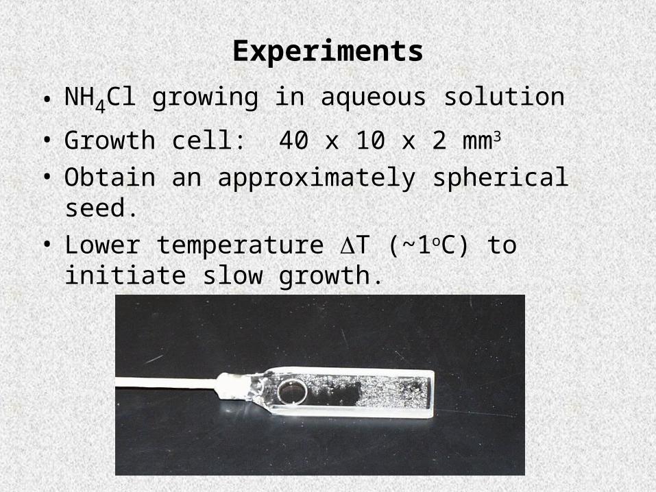
Experiments
• NH4Cl growing in aqueous solution
• Growth cell: 40 x 10 x 2 mm3
• Obtain an approximately spherical seed.• Lower temperature T (~1oC) to initiate slow
growth.
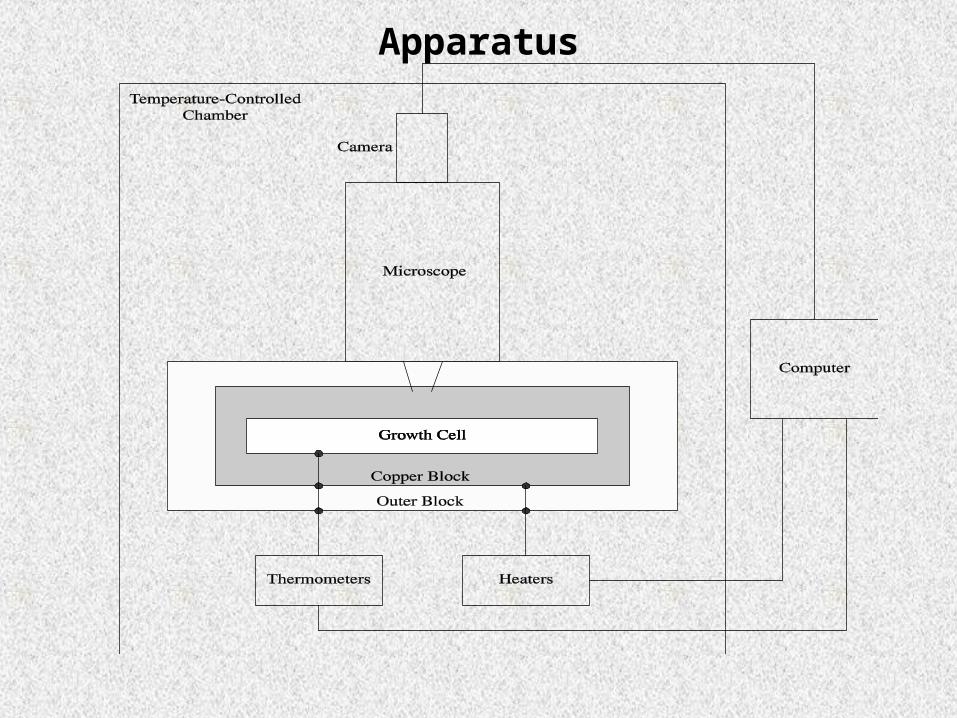
Apparatus
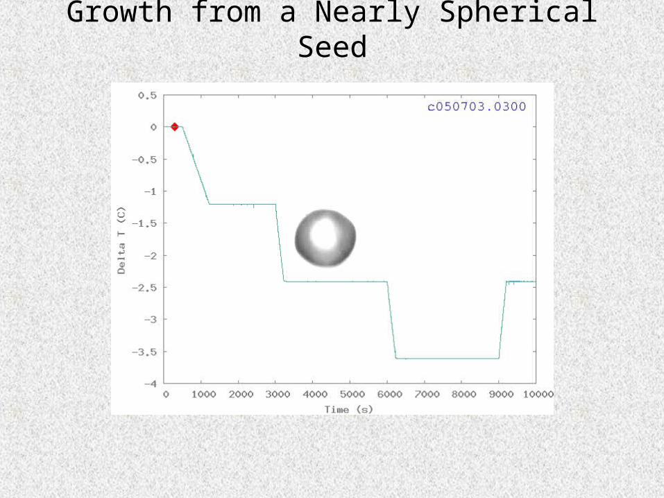
Growth from a Nearly Spherical Seed
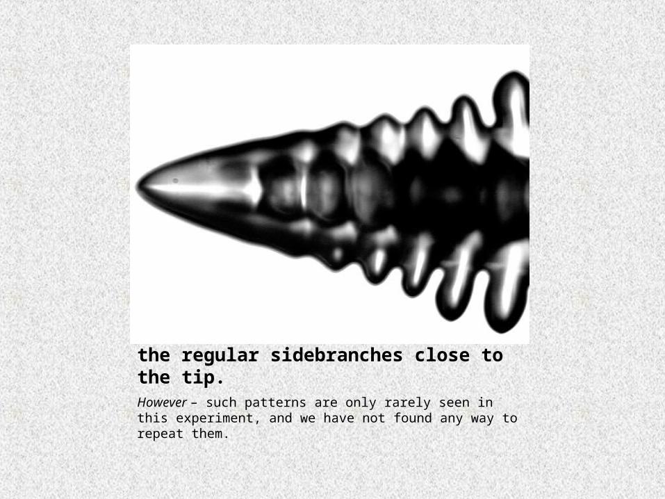
Apparent tip oscillations – note the regular sidebranches close to the tip.However – such patterns are only rarely seen in this experiment, and we have not found any way to repeat them.
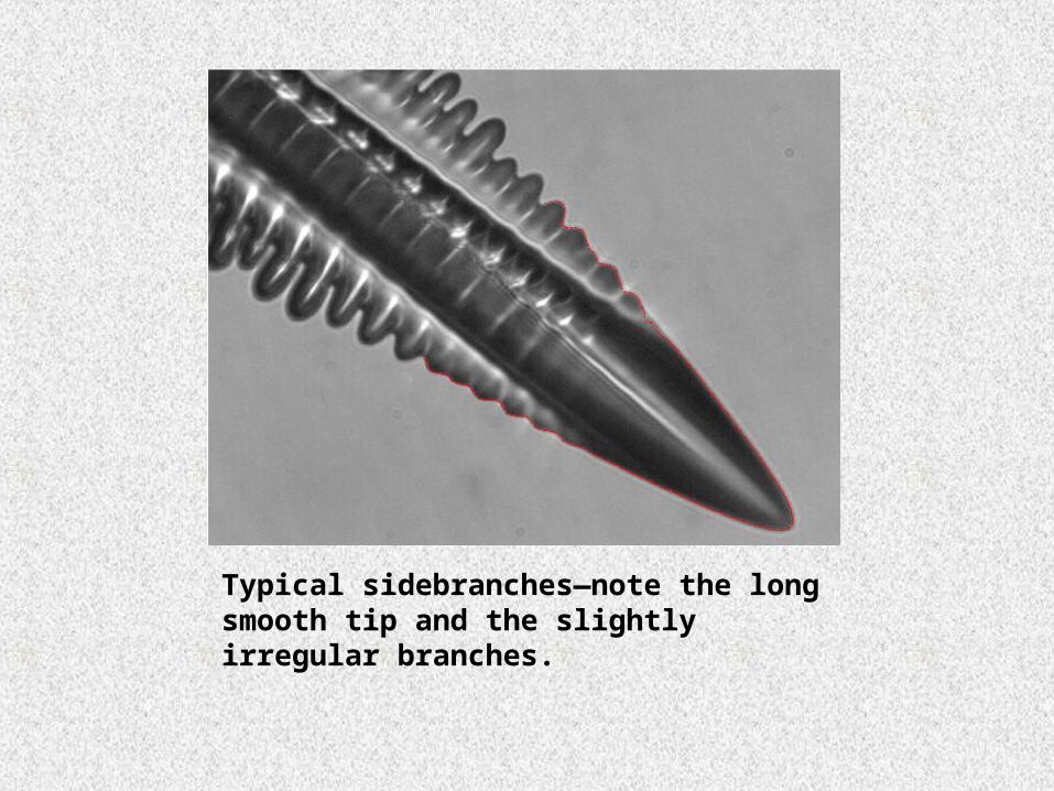
Typical sidebranches—note the long smooth tip and the slightly irregular branches.
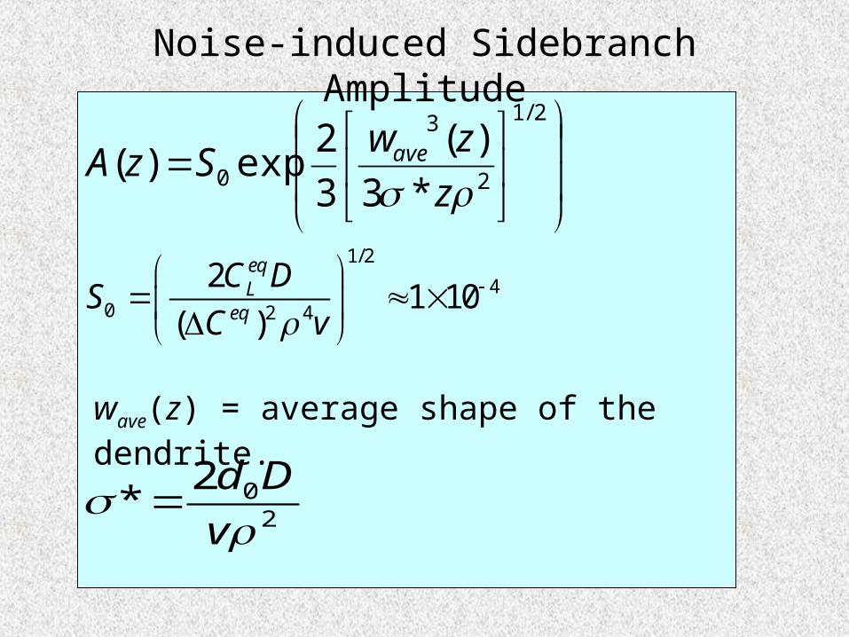
Noise-induced Sidebranch Amplitude
2/1
2
3
0 *3
)(
3
2exp)(
z
zwSzA ave
202
*
v
Dd
1/2
40 2 4
21 10
( )
eqL
eq
C DS
C v
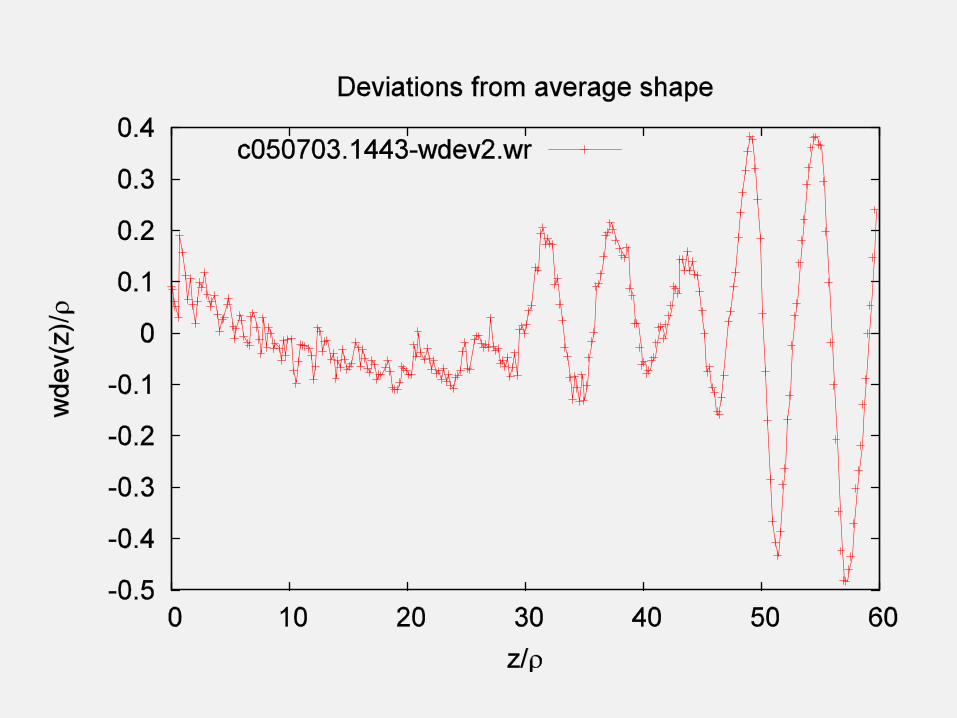
wave(z) = average shape of the dendrite.
Determining Materials Constants
d0: Capillary length: Measure the very slow growth and dissolution of an initially spherical seed.
v, and : Measure the tip of steady-state growing dendrites.
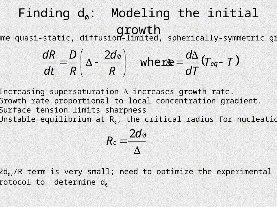
Finding d0: Modeling the initial growth
TTdT
d
R
d
R
D
dt
dReq
where
2 0
Assume quasi-static, diffusion-limited, spherically-symmetric growth:
•Increasing supersaturation increases growth rate.•Growth rate proportional to local concentration gradient.•Surface tension limits sharpness•Unstable equilibrium at Rc, the critical radius for nucleation.
•2d0//R term is very small; need to optimize the experimentalprotocol to determine d0
02dRc
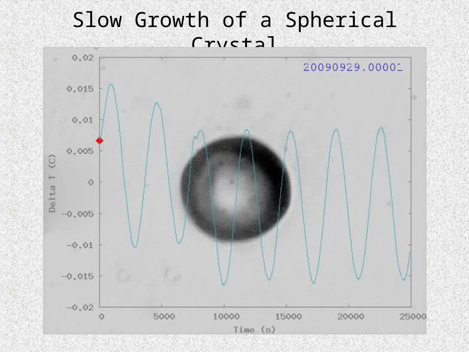
Slow Growth of a Spherical Crystal
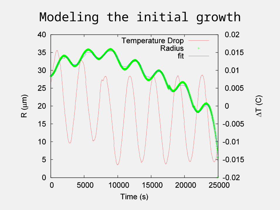
Modeling the initial growth
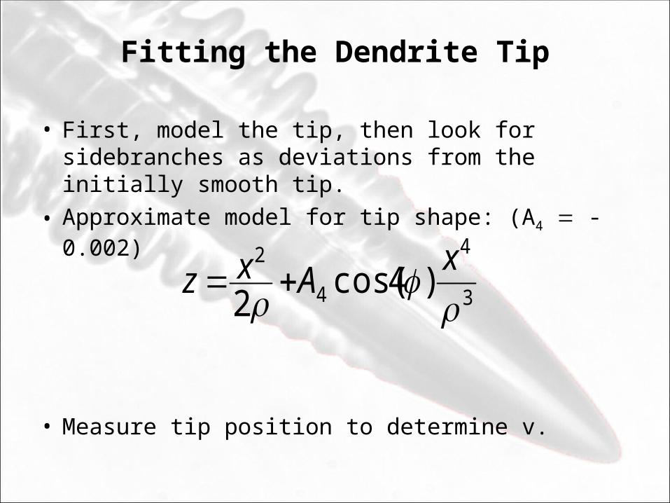
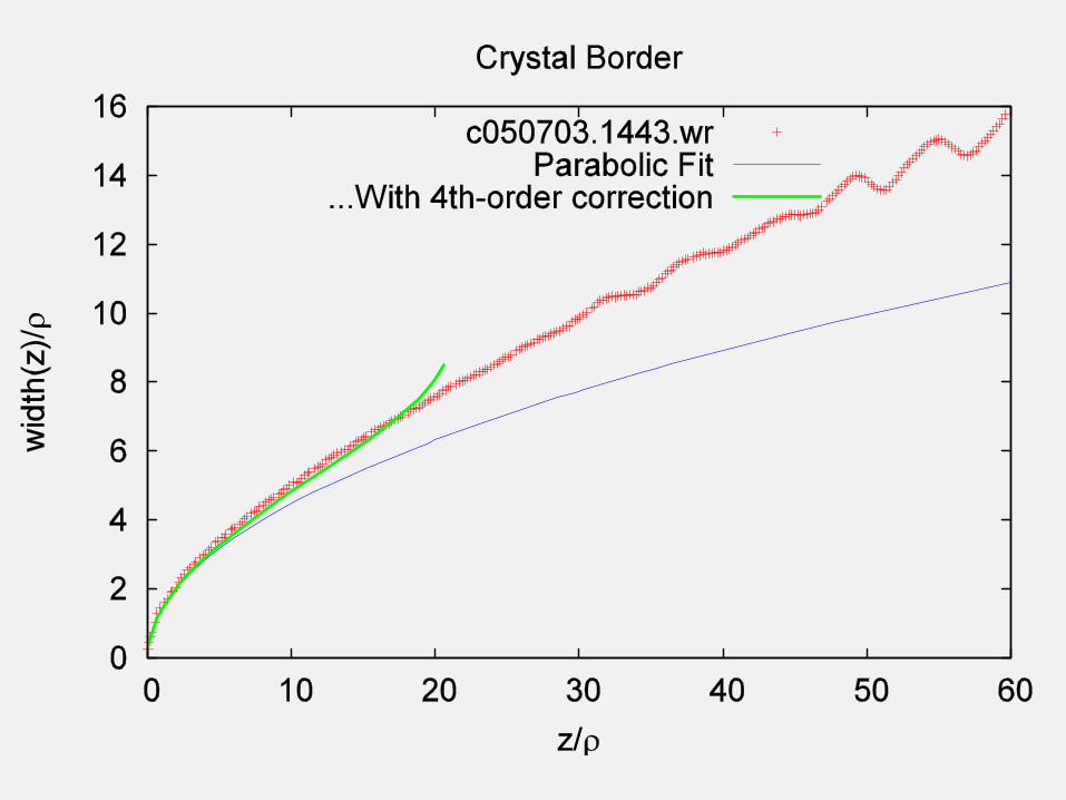
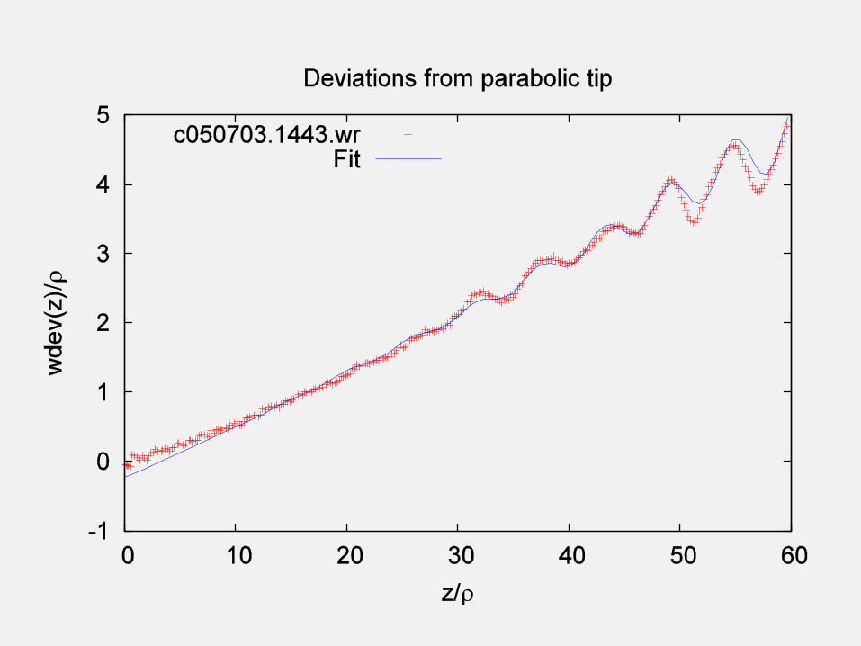
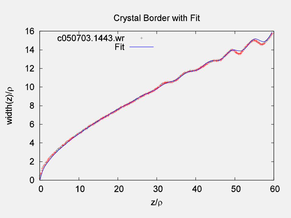
Fitting the Dendrite Tip
• First, model the tip, then look for sidebranches as deviations from the initially smooth tip.
• Approximate model for tip shape: (A4 -0.002)
• Measure tip position to determine v.
3
4
4
2
)4cos(2
x
Axz
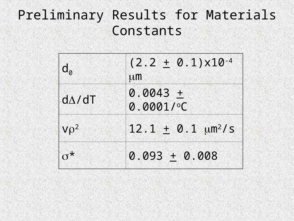
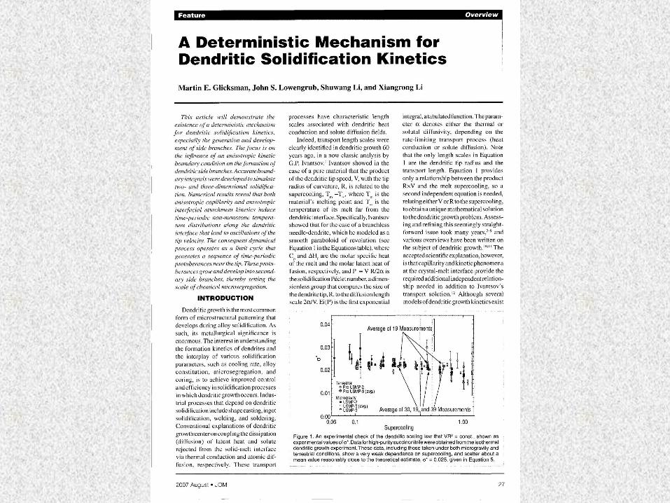
Preliminary Results for Materials Constants
d0 (2.2 + 0.1)x10-4 m
d/dT 0.0043 + 0.0001/oC
v2 12.1 + 0.1 m2/s
* 0.093 + 0.008

Noise-induced Sidebranch Amplitude
2/1
2
3
0 *3
)(
3
2exp)(
z
zwSzA ave
202
*
v
Dd
1/2
40 2 4
21 10
( )
eqL
eq
C DS
C v
wave(z) = average shape of the dendrite.
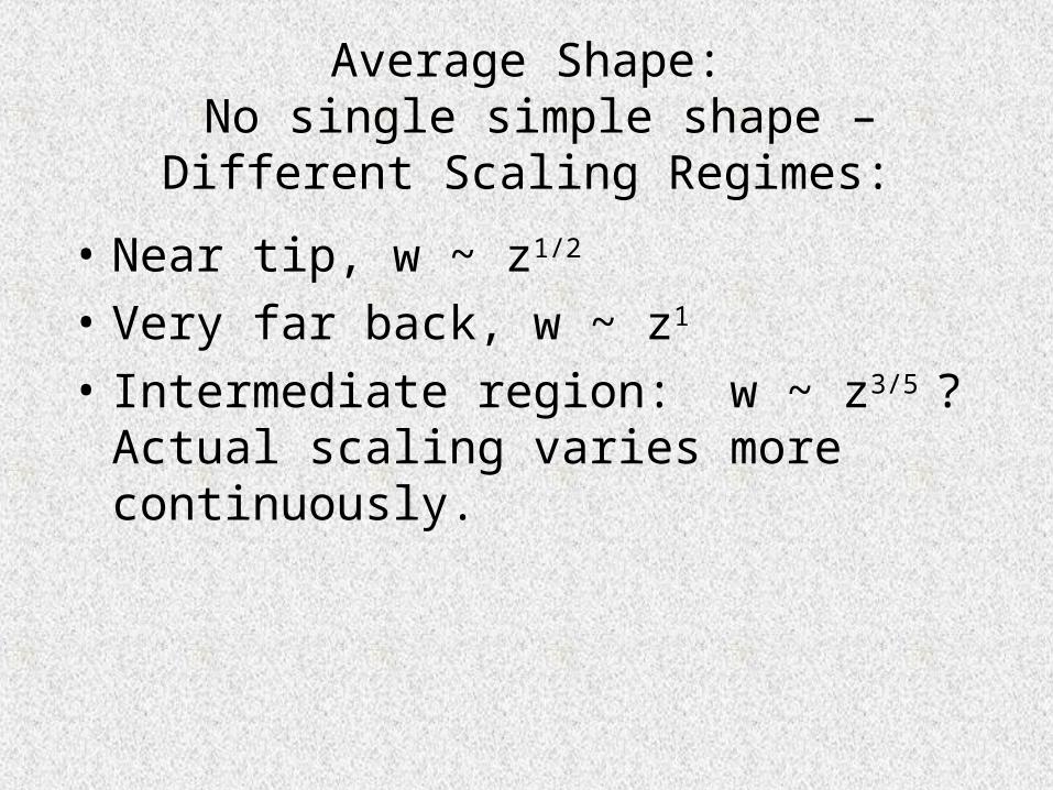
Average Shape: No single simple shape –Different Scaling Regimes:
• Near tip, w ~ z1/2
• Very far back, w ~ z1
• Intermediate region: w ~ z3/5 ? Actual scaling varies more continuously.
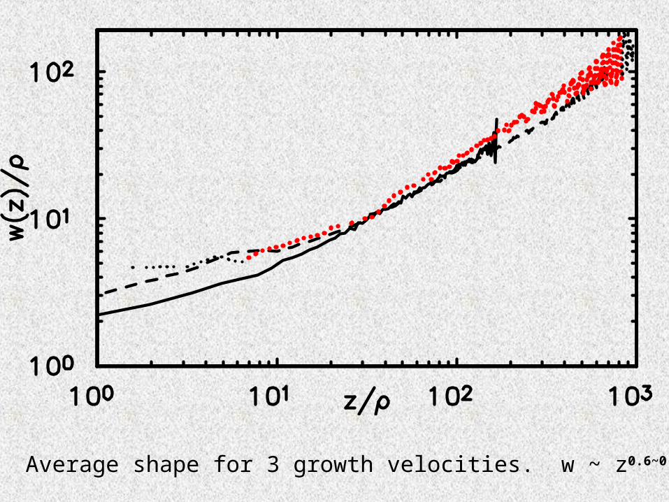
Average shape for 3 growth velocities. w ~ z0.6~0.8
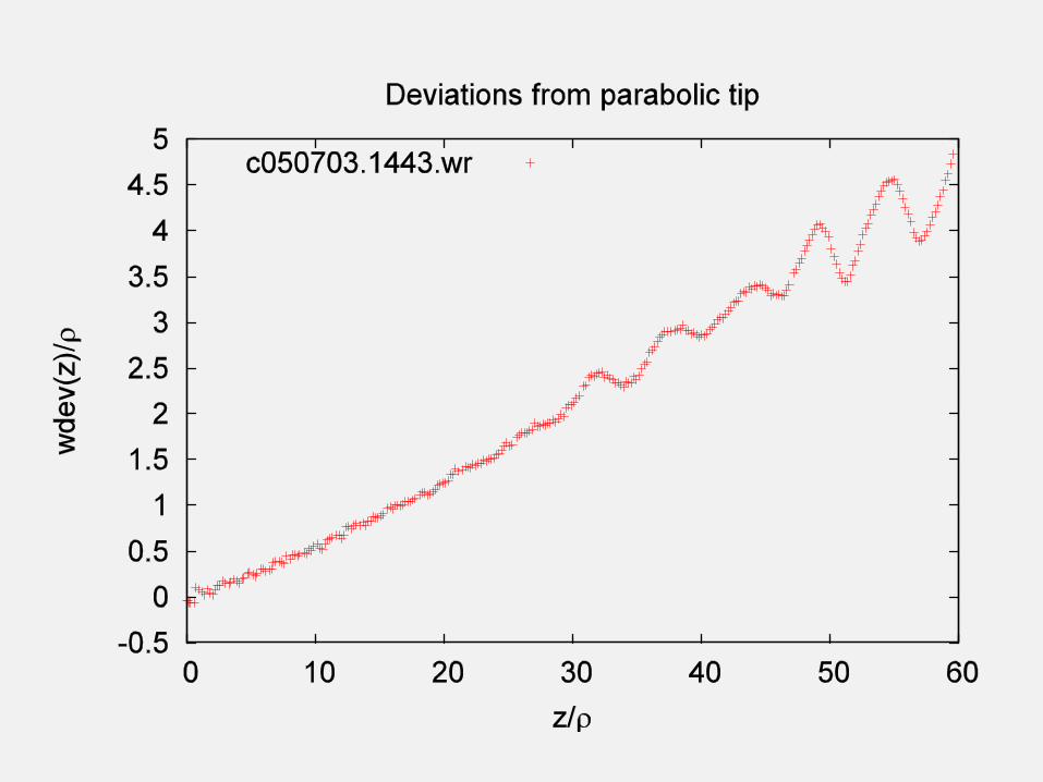
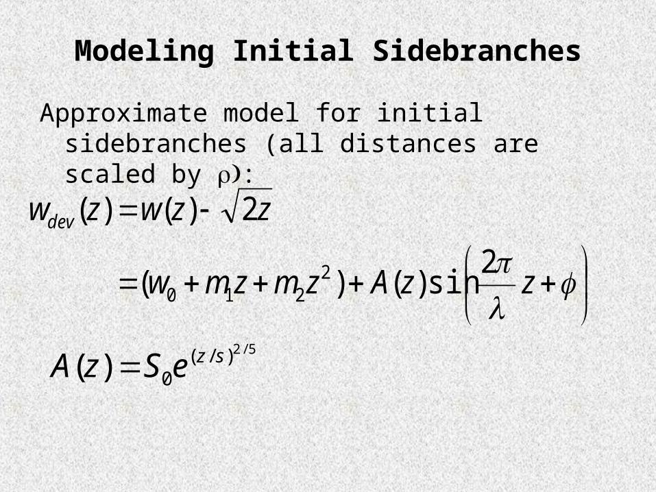
Modeling Initial Sidebranches
Approximate model for initial sidebranches (all distances are scaled by :
zzAzmzmw
zzwzwdev2
sin)()(
2)()(
2210
5/2)/(0)( szeSzA
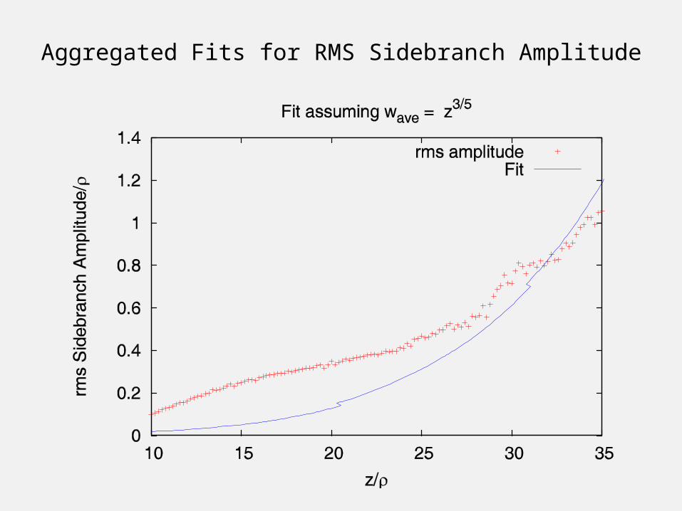
Aggregated Fits for RMS Sidebranch Amplitude
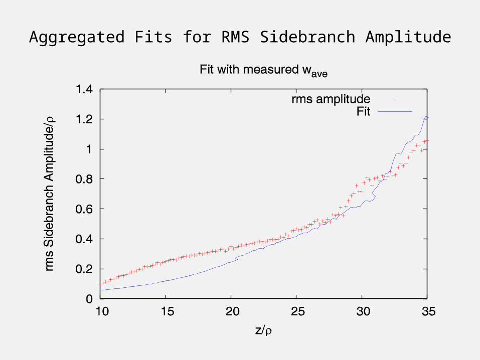
Aggregated Fits for RMS Sidebranch Amplitude
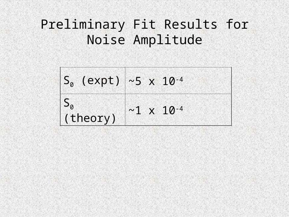
Preliminary Fit Results forNoise Amplitude
S0 (expt) ~5 x 10⁻⁴
S0 (theory) ~1 x 10⁻⁴
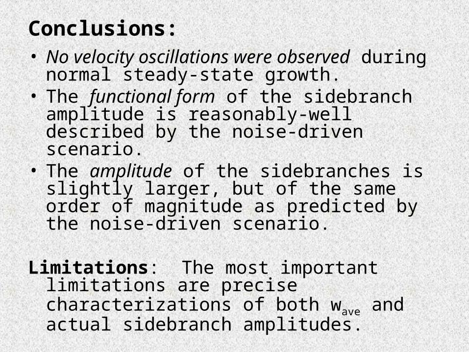
Conclusions:• No velocity oscillations were observed during
normal steady-state growth.• The functional form of the sidebranch amplitude
is reasonably-well described by the noise-driven scenario.
• The amplitude of the sidebranches is slightly larger, but of the same order of magnitude as predicted by the noise-driven scenario.
Limitations: The most important limitations are precise characterizations of both wave and actual sidebranch amplitudes.