Embed Size (px)
Citation preview
Anderson, David, and Thomson, Douglas (2014) Analyzing helicopter evasive maneuver effectiveness against rocket-propelled grenades. Journal of Guidance, Control and Dynamics, 37 (1). pp. 277-289. ISSN 0731-5090 Copyright © 2014 American Institute of Aeronautics and Astronautics A copy can be downloaded for personal non-commercial research or study, without prior permission or charge Content must not be changed in any way or reproduced in any format or medium without the formal permission of the copyright holder(s)
When referring to this work, full bibliographic details must be given
http://eprints.gla.ac.uk/67390/
Deposited on: 02 April 2014
Enlighten – Research publications by members of the University of Glasgow http://eprints.gla.ac.uk

1
Analysing Evasive Manoeuvre Effectiveness in
Helicopter Survivability Simulation
Dr David Anderson, Dr Douglas Thomson.
University of Glasgow, Glasgow, United Kingdom
It has long been acknowledged that military helicopters are vulnerable to ground-
launched threats, in particular the RPG-7 rocket-propelled grenade. Current helicopter
threat mitigation strategies rely on a combination of operational tactics and selectively-
placed armour plating which offer little protection. However in recent years a number of
active protection systems (APS) designed to protect land-based vehicles from rocket and
missile fire have been developed. These systems all use a sensor suite to detect, track and
predict the threat trajectory, which is then employed in the computation of a defensive
kill mechanism intercept trajectory. In this paper it is proposed that although a complete
APS in its current form is unsuitable for helicopters, the APS track and threat trajectory
prediction sub-system could be used in the computation of an optimal evasive
manoeuvre. It is further proposed that this manoeuvre can be found by solving a specific
pursuit-evasion differential game. To evaluate the game, nonlinear dynamic and spatial
models for a helicopter, RPG-7 round and gunner & evasion strategies were developed
and integrated into a bespoke simulation engine. Analysis of the results from
representative vignettes demonstrates that the simulation yields the value of the
engagement pursuit-evasion game. It is also shown that in the majority of cases
survivability can be significantly improved by performing an appropriate evasive
manoeuvre. Consequently this simulation may be used as an important tool for designing
and evaluating evasive tactics and manoeuvres leading to improved rotorcraft
survivability.
Introduction
ILITARY helicopters deployed in theatre are often required to participate in extremely dangerous combat
missions performing either close-air support or medical evacuation roles [1]. Although many different
threats exist on the modern battlefield, one of the most lethal engagements concerns an airborne platform
under attack by highly agile, high velocity short-range threats. Typical scenarios of this type of engagement
include attack from infra-red-guided surface-to-air missiles or unguided small-arms fire often deployed by
militia who, although poorly trained, are likely to be bold and determined in executing their operations, making
mission planning much more difficult. The significance of the threat to helicopter operations from unguided
munitions cannot be understated and rocket-propelled grenades (RPGs) in particular have historically been
extremely lethal, especially during low-speed nap-of-the-earth flight and in both take-off & landing flight
phases. For example, during the war in Vietnam 380 incidents were recorded involving engagement by RPGs
resulting in the catastrophic loss of 128 aircraft [2]. More recently insurgent and terrorist groups have used the
RPG to great effect, such as in the high-profile attack by Somali gangs in October 1993 when two US MH-60
Black Hawk helicopters were lost [3]. This threat has also been repeatedly highlighted during coalition
operations in west Asia, where rotorcraft have been shown to be particularly vulnerable, especially during take-
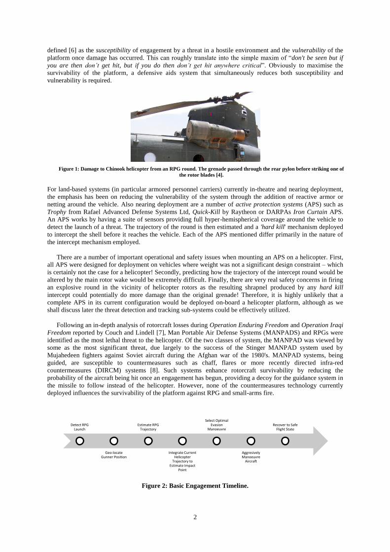
off or landing [4]. In Figure 1 the damage to an RAF Chinook helicopter is clearly seen with the round entering
the rear pylon and striking one of the rear rotor blades on exit. Fortunately in this incident all passengers and
crew escaped injury but often the outcome of such an engagement is catastrophic. In an attempt to better
understand and quantify the effects of an RPG strike, a number of research investigations have been undertaken,
the most recent of which involved live-fire testing of a number of RPG rounds against a complete AH-1
helicopter [5].
The branch of engineering dedicated to minimizing both the occurrence and impact of military system
engagements with hostile forces is known as survivability [6]. Platform survivability has long been a critical
design objective of any aircraft used in combat situations, whether their role is for close-air support,
troop/equipment deployment or intelligence, surveillance, reconnaissance (ISR) missions. Survivability may be
M
2
defined [6] as the susceptibility of engagement by a threat in a hostile environment and the vulnerability of the
platform once damage has occurred. This can roughly translate into the simple maxim of “don't be seen but if
you are then don’t get hit, but if you do then don’t get hit anywhere critical”. Obviously to maximise the
survivability of the platform, a defensive aids system that simultaneously reduces both susceptibility and
vulnerability is required.
Figure 1: Damage to Chinook helicopter from an RPG round. The grenade passed through the rear pylon before striking one of
the rotor blades [4].
For land-based systems (in particular armored personnel carriers) currently in-theatre and nearing deployment,
the emphasis has been on reducing the vulnerability of the system through the addition of reactive armor or
netting around the vehicle. Also nearing deployment are a number of active protection systems (APS) such as
Trophy from Rafael Advanced Defense Systems Ltd, Quick-Kill by Raytheon or DARPAs Iron Curtain APS.
An APS works by having a suite of sensors providing full hyper-hemispherical coverage around the vehicle to
detect the launch of a threat. The trajectory of the round is then estimated and a 'hard kill' mechanism deployed
to intercept the shell before it reaches the vehicle. Each of the APS mentioned differ primarily in the nature of
the intercept mechanism employed.
There are a number of important operational and safety issues when mounting an APS on a helicopter. First,
all APS were designed for deployment on vehicles where weight was not a significant design constraint – which
is certainly not the case for a helicopter! Secondly, predicting how the trajectory of the intercept round would be
altered by the main rotor wake would be extremely difficult. Finally, there are very real safety concerns in firing
an explosive round in the vicinity of helicopter rotors as the resulting shrapnel produced by any hard kill
intercept could potentially do more damage than the original grenade! Therefore, it is highly unlikely that a
complete APS in its current configuration would be deployed on-board a helicopter platform, although as we
shall discuss later the threat detection and tracking sub-systems could be effectively utilized.
Following an in-depth analysis of rotorcraft losses during Operation Enduring Freedom and Operation Iraqi
Freedom reported by Couch and Lindell [7], Man Portable Air Defense Systems (MANPADS) and RPGs were
identified as the most lethal threat to the helicopter. Of the two classes of system, the MANPAD was viewed by
some as the most significant threat, due largely to the success of the Stinger MANPAD system used by
Mujahedeen fighters against Soviet aircraft during the Afghan war of the 1980's. MANPAD systems, being
guided, are susceptible to countermeasures such as chaff, flares or more recently directed infra-red
countermeasures (DIRCM) systems [8]. Such systems enhance rotorcraft survivability by reducing the
probability of the aircraft being hit once an engagement has begun, providing a decoy for the guidance system in
the missile to follow instead of the helicopter. However, none of the countermeasures technology currently
deployed influences the survivability of the platform against RPG and small-arms fire.
Figure 2: Basic Engagement Timeline.
Detect RPG Launch
Geo-locate Gunner Position
Estimate RPG Trajectory
Integrate Current Helicopter
Trajectory to Estimate Impact
Point
Select Optimal Evasion
Manoeuvre
Aggresively Manoeuvre
Aircraft
Recover to Safe Flight State
3
To recap: none of the APS are suitable for helicopter installation, existing aircraft countermeasures are
ineffective against unguided threats and it is impractical to cover a helicopter in thick armor. Therefore the only
way to improve the survivability of a helicopter under RPG attack is to prevent detonation entirely, but if this is
not possible to manoeuvre the aircraft such that the impact point is as far as possible from any flight or mission
critical systems. Most currently deployed RPG’s, such as the RPG-7 with high-explosive anti-tank (HEAT)
warhead are impact devices [9], therefore the best possible survivability strategy is to estimate/predict the
trajectory of the incoming threat (as in the APS) and use this information to compute the optimal platform
manoeuvre to evade or otherwise reduce the lethality of this threat. The timeline of such a system would follow
a pattern similar (if not identical) to Figure 2. Following the logic presented here, evasive manoeuvres are
therefore the only reasonable way to increase helicopter survivability once engagement is initiated.
Proposing a survivability strategy based upon the premise of evasion may be conceptually simple, however
finding one is a complex function of platform & threat dynamics, á priori vulnerability analysis of the
helicopter, engagement geometry, environmental constraints and RPG electromagnetic signature. In devising a
viable strategy, a theoretical framework capable of describing the engagement (to be presented later) and data
against which the theory can be tested is essential. Obtaining appropriate RPG engagement data is problematic.
Experimental testing of evasive manoeuvre efficacy is obviously out of the question due to the unacceptable risk
to both crew and aircraft. The only viable approach is then to obtain test data via complex simulation.
The design and development of simulation tools to aid in the analysis and design of platforms and systems
with enhanced survivability is a growth research area internationally, but especially in the US and UK [2]. In the
US the Department of Defense (DoD), the Joint Aircraft Survivability Programme Office has established
SURVIAC (Survivability/Vulnerability Information Analysis Centre) for "collecting, analyzing, and
disseminating scientific and technical information related to all aspects of survivability and lethality". This
organization also maintains a library of modeling and simulation tools for both vulnerability and susceptibility
analysis, which interested parties can request from the website1. The aim is to provide a common and consistent
toolset for stakeholders to answer specific questions related to aircraft survivability. For example, simulating the
effectiveness of air defense artillery as reported in [10] uses gun, fixed-wing flight profiles and vulnerability
models from the SURVIAC library to calculate hit probability (PH) for an example vignette. Specific platform
and mission probabilities such as the probability of detection (PD), probability of hit conditioned on a particular
manoeuvre (one of the contributions of this paper, PH/M) and probability of a kill given a hit (PK/H) are examples
of the core building blocks in assessing mission-level survivability [6]. These probabilities are then used in an
integrated survivability model, the purpose of which is to provide a statistical estimate of platform survivability
for a particular vignette using ALL available information [2, 6]. Law [2] provides an excellent review of such
statistical models from a systems engineering perspective. His conclusion is that the accuracy of any integrated
survivability model depends upon the accuracy of constituent components used to create each probability
distribution, including the influence of tactics and evasion manoeuvres.
Recently, Anderson & Thomson have developed a mathematical model for simulating the RPG/Rotorcraft
engagement to evaluate the efficacy of various evasion strategies [11] using a bespoke multi-fidelity simulation
engine [12]. Known as MAVERIC (Modeling of Autonomous Vehicles using Robust, Intelligent Computing),
this simulation engine handles multiple dynamic agent models of differing fidelity and integrates them to
provide an accurate, computationally efficient solution to a user-defined vignette. In their simulation, a
nonlinear dynamic model containing both helicopter and RPG differential equations was solved to compute the
impact point for a particular scenario. In [11] only collective pitch deflection was considered for a number of
flight conditions and launch points, although this was sufficient to demonstrate the validity of the approach. This
work was subsequently enhanced in [13] to include longitudinal cyclic deflection and an examination of the
accelerations achievable at specific impact points using the extremities of the available control deflection. This
work was very similar to the RPG encounter model later developed by SURVIAC for modeling target
susceptibility to RPGs, the results of which were presented in a recent SURVIAC bulletin [14]. The SURVIAC
model also provides the probability of hit at a specific aim point but uses a singular circular-error-probable
(CEP) gunner accuracy model, a 2D representation of the aircraft and no maneuverability effects at all.
This paper presents a rigorous theoretical and mathematical framework for describing the scenario of a
helicopter under attack by ground-launched, unguided munitions (in this case an RPG) using dynamic game
theory and further presents a complex, nonlinear stochastic model capable of quantifying the survivability
statistics even in the presence of aggressive evasive manoeuvres. In the next section the theoretical and
mathematical framework used in defining the scenario is presented. This is followed by a definition of the
1 Available from http://www.bahdayton.com/surviac/index.htm
4
nonlinear helicopter model, both the existing flight mechanics model and a new method developed by the
authors for capturing the spatial extent (geometry) of the helicopter in a computationally efficient manner. Next
the RPG model is presented in two parts: the nonlinear model of the grenade dynamics and the effectiveness and
accuracy of the gunners' strategy. In the penultimate section the results of a number of example vignettes are
presented and the effects of the evasive manoeuvres chosen are demonstrated on the survivability statistics (the
hit probability or alternatively the value of the engagement differential game). Finally some conclusions and
recommendations for future work are presented.
Engagement Mathematical Model
A. Agent location & orientation
In deriving a mathematical model of an RPG engagement, the geometric representations and transformations
of the simulation entities were defined using the framework extensively documented in LaValle [15]. Begin by
defining the trajectory of agent ai as the particular solution of the general nonlinear state space representation of
the rigid-body equations of motion,
(1)
where for each agent ai, is the state trajectory, is the vector of control inputs and
represents the parameter set of any exogenous disturbance that may exert influence on the trajectory.
For example, if the effects of a crosswind were included in the simulation and the mathematical model used in
agent ai were completely parameterized by wind speed and direction, then . In
general the dynamic model for each agent is too complex to be solved analytically. Instead the trajectory is
computed using equation (2), [16].
(2)
where the integral term can be solved using any appropriate numerical integration technique. The state vector
will likely contain significantly more information than is required to model the physical interaction of two or
more agents. To describe interaction, define a world co-ordinate system using North-East-Down axes as
and the agent body-axis coordinate system . Next define the generalised coordinate as the pose of agent ai in world coordinates (note that the explicit time dependency has
been removed for brevity) where [x, y, z] are the translational positions of the centre of gravity and [ ] are
the Euler angles. Denote the position of the centre of gravity of agent ai in axes set as,
(3)
Similarly, the relative position of agent aj with respect to agent ai expressed in axes set is,
(4)
When the axes sets used by agents ai and aj are not collinear, the Euler sequence of rotations
are required to generate the direction cosine matrix (DCM) )3(SOC defining the relative rotation from
axes to . The principle DCM used in this investigation is the standard Euler transformation for converting
earth to body axes [17].
(5)
Therefore, defining the local co-ordinates of a point p on agent ai as , this point can be expressed in as
(6)
5
Finally, the position of agent aj with respect to point p on agent ai, expressed in is,
(7)
B. Geometric Modelling & Collision Detection
To model the rigid-body geometry of each agent ai, define a sequence of N primitives
that may be simply encoded into the simulation. To ensure that the integrity of the geometric model of
each agent is preserved, it is appropriate to define the co-ordinates of the primitive with respect to the agent
body axes system as follows,
(8)
where can be any polynomial with real-valued coefficients in . Then the spatial extent
of agent ai – the shape function – is defined as the union of all , i.e.
. Note that is
defined in , however to perform collision detection it is necessary to transform into by applying (6) to
every point in . Recalling the definition of the pose of agent ai, it is possible to re-write equation (6) in the
more general form,
(9)
where is the general form of the rigid-body transformation in (6). From this definition it immediately
follows that the position, orientation and geometry of agent ai is completely defined in by
(10)
Here is the set of all points on the surface and interior of agent ai expressed in . As we assume that
the shape function remains constant throughout the simulation, the explicit dependence of on has been
removed for notational convenience. The collision geometry is now trivial to define. Two agents ai and aj
collide when the following two conditions hold,
i.
ii.
These conditions represent a precise mathematical definition for all collisions, which include multiple
simultaneous collision points. However, for the purpose of the current study only the direct impact case is
important, not those scenarios where the RPG grenade grazes the airframe skin. For simplicity, assume that the
explosive center of the RPG and the center-of-gravity are coincident. Consequently the grenade geometry can be
neglected i.e. . Therefore the impact conditions simplify to , which means
that condition (i) is no longer relevant. However the point on the boundary of where intercept occurs
must still be determined.
Recall that as the generalized co-ordinates are time-dependent then, with reference to Figure 3, the intercept
conditions can be found by finding the time at impact timp where condition (ii) first holds i.e.
timp =
(11)
It is then possible to recover the relative position vector from (7), .

6
To find timp exactly requires an infinitely small T which is impractical in a numerical simulation, therefore
it will only be possible to determine timp to within the quantization error T. However let
(12)
Then the error in the impact point is a ball centered on
and bounded by,
(13)
where is the relative velocity between the grenade and the helicopter impact point at the impact
time determined from numerical simulation. As the maximum velocity of the RPG is 297m/s and a realistic
upper limit on the helicopter velocity is approximately 50m/s, an upper bound on the relative velocity is
350m/s. To achieve an error bound of O(3.5cm) requires a T of 100s. However this step size is much
smaller than that necessary to accurately integrate the RPG dynamics and would incorporate unnecessary
computational load. Fortunately MAVERIC agents contain a method for dynamically changing the time step at
specific points in the scenario. On each launch, once a collision has been detected using (11), the states of all
agents are wound back to timp-T and the simulation timestep reduced according to Tnew = * T, < 1. In all
simulations presented in this document = 0.01 was used.
C. Evasion Scenario
In this paper it is proposed that the helicopter/RPG evasion scenario can be modeled as a pursuit-evasion
differential game. A pursuit-evasion differential game is a particular form of zero-sum game where each player
is a dynamical system and adopts a specific strategy to either maximize (evade) or minimize (pursue) the value
of the game, given by an appropriate cost function [18, 19]. In an operational engagement scenario, the gunner
selects an aiming strategy formed from his/her own internal model of the helicopter dynamics and desired
impact point. This model is constructed by the gunner from observations of the helicopter, personal experience
and training in how to identify and predict helicopter motion. The engagement timeline is shown in Figure 4.
Figure 4: Engagement timeline.
time
increasing
tf
Final simulation
time (miss)
timp
RPG impacts
helicopter
tfire
Gunner fires
RPG
t0
Gunner
begins tracking
helicopter
Figure 3: Intercept geometry. For simplicity assume the
helicopter agent velocity << grenade agent
velocity.
7
Using this timeline a general gunner strategy is then,
(14)
where are the azimuth and elevation launch angles in and
is the gunners estimate of the helicopter pose. Essentially the gunners' strategy is based on how the
azimuth and elevation angles between gunner and helicopter change during the tracking phase of the
engagement. The gunner must select an appropriate intercept trajectory by estimating the future helicopter
trajectory, . As the gunner has no indication of how either the pilot or any active defensive system are
likely to react to a launch, the only reasonable assumption is that the helicopter will maintain the current
trajectory, although there is nothing in this formulation to prevent the adoption and testing of alternative aiming
strategies. In a similar manner the helicopter evasion strategy can be written as follows,
(15)
It is apparent from (15) that to obtain an optimal evasion strategy, the entity responsible for determining the
evasion strategy (either pilot or active evasion system) needs a good estimate of the threat pose during the
engagement, . This is exactly the functionality returned by the tracking and prediction subsystem in
existing APS, which therefore can be assumed available for the purposes of the current investigation in
manoeuvre effectiveness. The final two terms in helicopter strategy, are
required to calculate an estimate of the impact point and denote an estimate of the agent pose at time timp given
all information up to time . With both strategies defined, the pursuit-evasion differential game describing the
RPG evasion scenario may be defined as,
s.t.
(16)
where the cost function is,
(17)
The aim of this paper is to present a suitable model for determining and testing against realistic helicopter
strategies to yield the value of (16).
HGS Helicopter Model
A. Nonlinear Dynamics
Use has been made of the helicopter mathematical model, HGS (Helicopter Generic Simulation), developed
by Thomson [20]. HGS is a non-linear, seven degree of freedom, generic mathematical model, and was
developed to be suitable for use in an inverse simulation. Inverse simulation investigations typically involve
assessment of a helicopters capability to perform aggressive manoeuvres [21, 22], making HGS ideal for the
current investigation. Multi-blade representations of the main and tail rotor were used, each blade being
assumed rigid and to have constant chord and profile. The flow around the blades was assumed to be steady and
incompressible, thus allowing two-dimensional aerodynamic theory to be applied in calculating the blade
aerodynamic loads. Other significant features of the HGS include an engine model and look-up tables for
fuselage, tailplane and fin aerodynamic forces and moments. The mathematical model used in both simulations
is of a fairly standard generic form for rotorcraft. There are seven equations of motion, the six Euler rigid body
equations:
(18)
(19)
(20)

8
(21)
(22)
(23)
where standard notation has been used for the helicopter rigid-body states, external forces & moments and the
engine torque equation is given by,
(24)
where e1, e2, e3, K3 are the time constants and gain of the governor, and idle is the angular velocity of the
rotor in idle. The engine model and full derivation of the rigid body equations of motion are given in more
detail by Padfield [23]. These dynamic equations are augmented by the kinematic relationships defining the time
rate of change of Euler angles,
(25)
and the velocity of the helicopter in world axes,
(26)
The helicopter model then contains , a total of 14
states. Of course, these are general equations and the feature which distinguishes them as helicopter equations of
motion is the composition of the external forces and moments X, Y, Z, L, M and N (and the engine torque QE).
These forces and moments are periodic due to the once per revolution flapping/lag/pitch motions of a main rotor
blade. The HGS model however is simplified by disregarding the lag and blade pitch dynamics and assuming
that the flap dynamics can be treated as quasi-steady. This is an acceptable assumption as firstly, blade flap
motion is much more influential in terms of predicting blade loads (hence lag and pitch motion can be ignored)
and the blade dynamics are much faster than those of the body modes. As discussed by Padfield [23], this
assumption allows a multi-blade disc representation of the main rotor to be formed which is time-invariant in
trim. More comprehensive models include full dynamic representation of the dynamics of each blade
separately.
The question of the validity of the results is also important - if any meaningful information is to be derived
then the mathematical model must replicate the actions of the real aircraft. In the case of HGS, inverse
simulation has been used whereby trajectory data from manoeuvres flown by real helicopters is used to drive the
inverse simulation. The states and controls computed by HGS (in its inverse formulation) are compared with
those recorded in the flight tests to establish the validity of the simulation, and results have demonstrated
acceptable correlation for a range of manoeuvres [21, 24]. The HGS model is generic in structure, representing
single main and tail rotor helicopters by a series of basic configuration parameters. It is then possible to
simulate a wide range of different rotorcraft by developing appropriate data files for specific types.
B. Bounding Ellipsoid
Completion of the helicopter agent model also requires the specification of the spatial model, . In the ideal
case, the spatial model is a photorealistic computer generated 3D representation of the aircraft created using a
powerful 3D modeling package such as Maya or 3D Studio Max. Almost all complex 3D models are generated
using a tessellation process where the geometry is represented by a mesh of triangular polygons. With respect to
the process introduced in earlier, each polygon forms a plane which defines a half-space primitive. Collision
detection could be performed on each polygon in the mesh, but a much more computationally efficient method
is to create a 'bounding box' around the mesh – a method almost universally used in 3D computer games [25].
9
Top view
Rear View
Side View
Figure 5: Bounding ellipsoids around the DRA Lynx helicopter (underlying Lynx schematic from
Padfield [23]).
Following some trial and error, it was found that the best primitive shape to define a bounding box for the
helicopter is an ellipsoid. This finding is illustrated in Figure 5 above which shows how four ellipsoids can very
accurately capture the shape of the Westland Lynx helicopter used in this study (see Padfield [23] for more
information on this particular aircraft). All of the pertinent components and subsystems in the Lynx are
contained within the four ellipsoids with only a very slight overlap, the worst example of which is seen in the
side view, immediately to the front of the aircraft. Overall, these four primitives provide a very accurate
representation of the helicopter.
Another attractive property of using an ellipsoid as the primitive is the simplicity of the equations defining
the shape boundary. Each ellipsoid is defined in body axes by the following equation,
(27)
where
is the position in body axes of the centre of the i
th ellipsoid and are the semi-
major axes lengths along the x, y, z axes respectively. The relative position of grenade with respect to helicopter
cg,
lies on the surface of the ellipsoid when the equality holds and on
the interior of the primitive when the inequality holds. Collision detection following the definition in equation
(11) is then trivial.
RPG-7 Threat Model
The Ruchnoy Protivotankovy Granatomyot (RPG) is a soviet-made antitank grenade launcher first
introduced in 1962 [9]. Since then this weapon has proven to be both lethal and versatile in all of the main
conflicts of the latter part of the 20th
century, from Vietnam and Northern Ireland [9] to Iraq and Afghanistan.
Part of this popularity is due to the mobility offered to the artilleryman and the rugged construction of the
weapon. Essentially, the weapon consists of a launcher that is used by the artilleryman to aim the weapon
through an optical sight and an explosive projectile – normally a HEAT (High Explosive Anti-Tank) round. The
engagement is divided into two main sections; the initial ejection from the launcher by a small strip of powder
charge, accelerating the projectile to 117m/s, followed approximately 11m from the launcher by a sustainer
rocket ignition to boost the rocket to a maximum velocity of 294m/s. This two-stage launch reduces backblast
and protects the gunner. The launch sequence is shown in Figure 6.
10
Figure 6: RPG-7 Launch sequence (figure reproduced from [9]).
Additional stabilization in flight is achieved via the deployment of four fins at the rear of the projectile,
Figure 7. These fins provide two functions. First, the drag induced by the fin aerodynamics provides a
stabilizing moment to the projective trajectory and second the fins sustain and increase the stabilizing spin
around the roll axis induced as the rocket is expelled from the tube.
Figure 7: RPG-7 in-flight configuration.
A. Dynamic Model
When simulating the RPG-7 grenade precisely, both aerodynamic and inertial effects should be modeled.
For the current problem the output required is the kinematic trajectory expressed in inertial axes. If we assume
that the grenade is spin-stabilized, then in a vacuum the trajectory will become that of a simple point-mass
subject to a time-varying thrust in a gravitational field – a ballistic problem. However, in [9] the rocket
trajectory is shown to be sensitive to a cross-wind, which means that some aerodynamic calculations are
required. The modeling strategy used here was to simplify the projectile into a centre-of-mass and a centre-of-
pressure, Figure 8.
Figure 8: Simplified RPG free-body diagram.
Using this free-body diagram it is simple to construct a 12-state, 6DoF model for the RPG-7 using equations
(18) to (23) and (25), (26). The external forces and moments applied to the grenade can be decomposed into
those arising from propulsive, aerodynamic and gravitational sources. As in the helicopter case, the gravitational
model may be considered constant due primarily to the distances involved in the engagement (the engagement
simulation may be tailored to a specific global location by altering the local gravity vector from WGS-48 [26],
although this is unlikely to lead to any appreciable improvement in simulation accuracy). Considering the
propulsive forces, the only reliable open-source information the authors were able to obtain regarding the rocket
dynamics comes from a US Army training document, [9]. Here the launch timeline is given in Figure 6 and from
this information one can recover the speed profile shown in Figure 9 (a). Unfortunately the rocket speed is a
function of not only the propulsive forces but also the aerodynamic forces.
l
D
x T
y mg
Vf
c.g.
c.p.
xE

11
From Figure 7 it is clear that the RPG-7 grenade has multiple surfaces likely to induce aerodynamic loads.
As no published information documenting these loads exists in the open-source literature, local aerodynamics
(especially in the neighborhood of the warhead) have to be ignored with only those forces likely to have a
significant effect on the RPG trajectory – the stabilizer fins – included. The purpose of the stabilizer fins is to
provide a stabilizing drag force aft of the centre-of-gravity (in much the same manner as the fletching on an
arrow) which ensures that the RPG points along the velocity vector. Denoting the cumulative drag from all four
stabilizer fins by , and assuming that each fin acts like a thin aerofoil, then the drag is proportional to the
square of the local velocity at the cp (centre of pressure) point. The local velocity is obtained by combining the
translational velocity of the grenade in body axes , the angular rate vector and the offset between the cp
and the centre-of-gravity as follows,
(28)
However, in calculating the aerodynamic forces, any atmospheric crosswinds must also be included. The
velocity, angle of attack and sideslip angles at the cp are then,
(29)
(30)
(31)
The external forces and moments acting on the grenade are then,
(32)
(33)
All that remains is to define the thrust profile function to match the speed profile. Again the
thrust profile of an RPG-7 warhead is not available in the public domain. Following a process of trial and error,
an ad-hoc function was found for the thrust profile by matching the RPG in-flight timeline presented in Figure 6.
Figure 9: Example RPG trajectories. (a) is the velocity profile and (b) the impact of a 10m/s crosswind.
As shown in Figure 9 (a) the velocity profile matches the launch sequence described in Figure 6. The main
uncertainty here is the time constant governing the transition from the launcher exit velocity of 117m/s until the
final velocity of 294m/s, which cannot be accurately specified without detailed information of the temporal
thrust profile and drag characteristics of the projectile. The sensitivity of the rocket to a crosswind is shown in
Figure 9 (b). Precise information regarding the dynamic response of the RPG-7 class of rocket-propelled
grenades is, unsurprisingly, also unavailable in the public domain. Therefore, the modeling activity undertaken
12
employed a significant degree of engineering judgment combined with previous airborne dynamic system
modeling expertise and some limited performance metrics. The RPG-7 dynamic model is qualitative rather than
precise, but this is perfectly acceptable for the current investigation.
B. Gunner Accuracy Model
Modeling the accuracy of the gunner is one of the most challenging aspects in the simulation. Accuracy is a
complex function of the scenario geometry, environmental conditions and the experience and capability of the
gunner. The latter two aspects to the problem are very difficult for a civilian university department to properly
address as such information – typical enemy combatant (EC) experience and threat level with an RPG-7 weapon
– is likely classified. However, through careful thought experiment a probability simulation scenario based upon
a modification of the classical circular error-probable (CEP) method [6] for describing artillery accuracy was
developed. While the actual EC accuracy values may be incorrect, such information is not required to
demonstrate the efficacy of the simulation.
It is assumed that the gunner accuracy may be adequately captured via the appropriate combination of two
factors – accuracy against a static target (the CEP) and accuracy in predicting the lead angle necessary for
intercept (the error probable or EP component), Figure 10. Both components of accuracy can be described using
a standard Gaussian normal distribution for each engagement angle, expressed using the bivariate distribution,
(34)
where is the mean, and is the standard deviation of each of the gunner launch angles, . It is
common practice in artillery modeling to specify the CEP as radius around the target in meters. To convert this
to angles, a nominal range is required which in this case is 100m. To obtain the EP contribution to each of the
launch angles, the average gunner angles during the tracking phase (see equation (14)) are used. The EP value as
specified by the user is then distributed between the azimuth and elevation angles according to their relative
magnitudes. The final variance values supplied to the bivariate normal distribution generation function are then
the square of the root-sum-square (RSS) of the CEP and EP. As an example, consider Figure 11 below.
Figure 10: Engagement geometry
Figure 11: Joint probability distribution – 2m CEP, 3m lead angle EP, port side engagement.
79.5
80
80.5
9
10
11
12345
azimuth angle (deg)
pdf(obj,[x,y])
elevation angle (deg)
azimuth angle (deg)
ele
vation a
ngle
(deg)
pdf(obj,[x,y])
79.5 80 80.59.5
10
10.5
lead
angles
engagement
angles
CEP

13
Finally, in defining the launch angle pdf the mean value remains to be found. Again this is a function of the
gunners experience, geometry and intent (e.g. to disable the aircraft or specifically target the crew), but can be
captured mathematically as the solution of the following nonlinear program.
s.t.
(35)
This is similar to the differential game describing the evasion manoeuvre presented earlier (equation (16))
with only a few slight modifications and can be solved numerically using for example the fmincon optimization
routine in MATLAB. The main addition to the simulation component is the extension of the helicopter vector of
generalized co-ordinates q to include the axes transformation necessary to return the gunners aim point on the
helicopter airframe, qaim (see Figure 12). In the examples to follow, the typical value of this cost function (i.e.
optimal gunner error) was less than 1cm.
(a) (b) (c)
Figure 12: Illustration of the effect of the aim-point offset using a portside engagement at 300m. In (a),
the gunner is aiming for the helicopter centre, in (b) the pilot and (c) the tailrotor. An additional standard
deviation of 10cm CEP was added solely for illustrative purposes.
RESULTS
A. Aircraft Survivability Simulation to Earth-launched Threats (ASSET)
In 2011, GU began work on a rotorcraft RPG evasion strategy simulation tool to investigate and quantify
helicopter survivability to an ambush by multiple RPGs during the landing phase into a forward operating base
[27]. A Graphical User Interface (GUI) was developed with user-input controls to both define the scenario and
display the results. The simulation engine was derived from a subset of the MAVERIC libraries. A snapshot of
the GUI is shown in Figure 13.
(a) (b)
Figure 13: ASSET RPG simulation. (a) Main GUI window and (b) evasive manoeuvre specification
window.
14
When ASSET is run there are two main outputs returned – the hit probability for the engagement modeled
and a 3D plot of the hit locations on the helicopter airframe (ellipsoid approximation). To illustrate the typical
output from this plot, consider a low-speed nap-of-the-earth scenario of a 20knot flight at an altitude of 30m
encountering a threat ahead and to port of the aircraft, Figure 14. One of the standard evasive manoeuvres taught
to pilots is to rapidly apply collective pitch, Figure 14 (b). In this scenario, the upward translation is seen, but
due to the collective-induced yaw the cross-sectional area presented to the gunner is increased, reducing
survivability. Through trial and error, a combination of collective, aft longitudinal cyclic, hard port lateral cyclic
and full tailrotor collective (left pedal) gives the manoeuvre in Figure 14 (c). Here, there is both a translational
displacement and favorable attitude angle change that results in minimal cross-sectional area presented to the
gunner. This manoeuvre is 4 times more effective than the standard collective.
(a) (b) (c)
Figure 14: Example ASSET output. (a) Shows the Monte-Carlo simulation results for the trim case, (b)
the effect of applying collective pitch and (c) the evasion possible through proper selection of controls.
Crosses indicate a hit, circles a miss.
B. Statistical Reliability of Monte-Carlo Method
In addition to calculating engagement geometries for use in an automatic evasion system, one of the primary
outputs of this simulation is the hit probability for a specific scenario. Computation of the hit probability is
achieved by applying the following equation,
if impact detected
other ise (36)
This may be further conditioned by the helicopter trajectory, either trim ( ) or manoeuvre ( . It is well
known that the statistical accuracy of a Monte-Carlo approach improves by increasing the number of runs, N.
However there is a trade-off between acceptable statistical accuracy and simulation run time. Table 1 shows the
hit probabilities obtained for a typical engagement scenario run 5 times for 5 different Monte-Carlo settings. It is
easily observed that there is a run-to-run deviation in the hit probability obtained, however the standard
deviation between simulations decreases as the number of Monte-Carlo runs increases, as expected. Looking at
the average PH, there is a noticeable difference between the first entry (250 runs, average 56%) and the rest
(average 58%). Also there is no significant practical difference between the simulation accuracy defined with
respect to the standard deviations returned by using 3000 Monte-Carlo runs and 500. Consequently, 500 Monte-
Carlo runs were used to generate the results to follow.
15
Table 1: Hit probability mean and standard deviation for a typical engagement scenario.
Number of Monte-Carlo Runs (N)
250 500 1000 2000 3000
PH (%)
57.6 60.4 59.1 58.5 59.2
54.4 57.6 57.4 57.2 57.73
59.2 55.8 59.2 56.55 56.7
55.2 59.2 56.5 59.55 58.1
54.8 57.8 56.7 58.35 57.23
STD (%) 2.07 1.74 1.295 1.174 0.95
AVERAGE (%) 56.24 58.16 57.78 58.03 57.8
TIME (s) 32 63 121 242 485
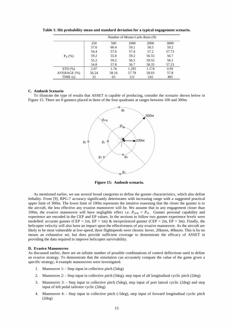
C. Ambush Scenario
To illustrate the type of results that ASSET is capable of producing, consider the scenario shown below in
Figure 15. There are 8 gunners placed in three of the four quadrants at ranges between 100 and 300m.
As mentioned earlier, we use several broad categories to define the gunner characteristics, which also define
lethality. From [9], RPG-7 accuracy significantly deteriorates with increasing range with a suggested practical
upper limit of 300m. The lower limit of 100m represents the intuitive reasoning that the closer the gunner is to
the aircraft, the less effective any evasion manoeuvre will be. We assume that in any engagement closer than
100m, the evasive manoeuvre will have negligible effect i.e. PH/M = PH. Gunner personal capability and
experience are encoded in the CEP and EP values. In the sections to follow two gunner experience levels were
modelled: accurate gunner (CEP = 1m, EP = 1m) & inexperienced gunner (CEP = 2m, EP = 3m). Finally, the
helicopter velocity will also have an impact upon the effectiveness of any evasive manoeuvre. As the aircraft are
likely to be most vulnerable at low-speed, three flightspeeds were chosen: hover, 20knots, 40knots. This is by no
means an exhaustive set, but does provide sufficient coverage to demonstrate the efficacy of ASSET in
providing the data required to improve helicopter survivability.
D. Evasive Manoeuvres
As discussed earlier, there are an infinite number of possible combinations of control deflections used to define
an evasive strategy. To demonstrate that the simulation can accurately compute the value of the game given a
specific strategy, 4 example manoeuvres were investigated.
1. Manoeuvre 1: - Step input in collective pitch (5deg)
2. Manoeuvre 2: - Step input in collective pitch (5deg), step input of aft longitudinal cyclic pitch (2deg)
3. Manoeuvre 3: - Step input in collective pitch (5deg), step input of port lateral cyclic (2deg) and step
input of left pedal tailrotor cyclic (2deg)
4. Manoeuvre 4: - Step input in collective pitch (-5deg), step input of forward longitudinal cyclic pitch
(2deg)
100m
g8
300m
g5
g3
g4
g2
g7
g1
g6
Figure 15: Ambush scenario.

16
All of these controls are passed through a first-order lag with a time constant of 100msec. The reason for this
smoothing filter is to first include a lag that covers both actuator dynamics in the swashplate & tailrotor
collective controls and dynamic inflow through the main rotor. To illustrate the effect on the helicopter
trajectory of applying these control inputs, the response to manoeuvre 1 is shown in Figure 16 for each of the
flightspeeds of interest. It was assumed that the aircraft was flying in trim, heading due north and that the
manoeuvre was applied for 4secs. Also shown is a very short-range engagement RPG trajectory which is
included purely for illustrative purposes.
(a) (b) (c)
Figure 16: The effect of manoeuvre 1 on the helicopter trajectory at (a) hover, (b) 20kts and (c) 40kts.
Considering the hover case first, the application of collective pitch should increase the altitude of the
aircraft, which it clearly does. The other major change is to the heading. As the collective pitch is increased this
increases the mean angle of attack of the disc which then increases the lift on each blade segment (hence the
increase in thrust), but also increases the drag that leads to increased rotor torque (i.e. main rotor torque
balanced in trim by the tailrotor). The net result is an angular acceleration around the body vertical axis resulting
in the observed heading change. If the aircraft is in forward flight, the additional lift (from increased dynamic
pressure) also creates a nose-up pitching moment which is coupled into a rolling moment via the yaw rate. The
severity of this effect is a function of the forward airspeed as can be seen by comparing the 20knot and 40knot
cases where the pitch angle for the 40knot case is much greater. To summarise, these results demonstrate that
the mathematical model is responding as expected to the control inputs applied.
E. Manoeuvre Effectiveness Parameter
For obvious reasons, we do not intend to present predicted hit probabilities for specific engagement
scenarios – the main output from ASSET – in the open literature. Instead, the results of the simulations will be
presented using a more appropriate metric, the manoeuvre effectiveness parameter ) defined as,
(37)
where is the run-to-run standard deviation for the selected number of Monte-Carlo runs. The manoeuvre
effectiveness parameter will then return 100% only if the manoeuvre attains complete evasion and 0 if it has
negligible effect. This parameter has the attractive property of easily conveying and quantifying the action of a
manoeuvre for a specific scenario while simultaneously concealing the actual hit probabilities. Therefore, the
results presented shortly should not be interpreted as hit probabilities. Any attempt to do so from the data
presented in the sequel is futile.
F. Simulation Data
As stated earlier, there are two principal uses for the data generated by this simulation. First to generate hit
probabilities conditioned by helicopter manoeuvres (manoeuvre effectiveness) for inclusion in statistical
survivability meta-models (PH/M). Second, analysis of manoeuvre effectiveness in response to a single-round
engagement, used to provide evaluation data required in the design of an active manoeuvre system (AMS). The
following sections will give examples of data generated for both purposes.
17
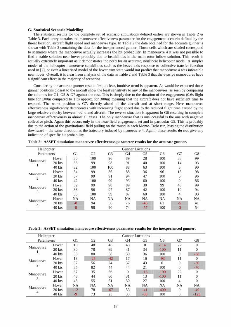
G. Statistical Scenario Modelling
The statistical results for the complete set of scenario simulations defined earlier are shown in Table 2 &
Table 3. Each entry contains the manoeuvre effectiveness parameter for the engagement scenario defined by the
threat location, aircraft flight speed and manoeuvre type. In Table 2 the data obtained for the accurate gunner is
shown with Table 3 containing the data for the inexperienced gunner. Those cells which are shaded correspond
to scenarios where the manoeuvre actually increases the hit probability. In manoeuvre 4 it was not possible to
find a stable solution near hover probably due to instabilities in the main rotor inflow solution. This result is
actually extremely important as it demonstrates the need for an accurate, nonlinear helicopter model. A simpler
model of the helicopter manoeuvre capabilities such as the heave axis response to collective transfer function
used in [2], or even a linearised model of the hover trim state would not predict that manoeuvre 4 was infeasible
near hover. Overall, it is clear from analysis of the data in Table 2 and Table 3 that the evasive manoeuvres have
a significant effect in the majority of scenarios.
Considering the accurate gunner results first, a clear, intuitive trend is apparent. As would be expected those
gunner positions closest to the aircraft show the least sensitivity to any of the manoeuvres, as seen by comparing
the columns for G1, G5 & G7 against the rest. This is simply due to the duration of the engagement (0.6s flight
time for 100m compared to 1.3s approx. for 300m) meaning that the aircraft does not have sufficient time to
respond. The worst position is G7, directly ahead of the aircraft and at short range. Here manoeuvre
effectiveness significantly deteriorates with increasing flight speed due to the reduced flight time caused by the
large relative velocity between round and aircraft. The reverse situation is apparent in G6 resulting in complete
manoeuvre effectiveness in almost all cases. The only manoeuvre that is unsuccessful is the one with negative
collective pitch. Again this occurs only in the near-field engagement set and in particular G5. This is probably
due to the action of the gravitational field pulling on the round in each Monte-Carlo run, biasing the distribution
downward – the same direction as the trajectory induced by manoeuvre 4. Again, these results do not give any
indication of specific hit probability.
Table 2: ASSET simulation manoeuvre effectiveness parameter results for the accurate gunner.
Helicopter Gunner Locations
Parameters G1 G2 G3 G4 G5 G6 G7 G8
Manoeuvre
1
Hover 30 100 96 89 28 100 38 99
20 kts 33 99 98 91 40 100 14 93
40 kts 32 100 100 88 63 100 5 90
Manoeuvre
2
Hover 34 99 86 88 36 96 15 98
20 kts 57 99 91 94 47 100 6 96
40 kts 42 100 99 93 60 100 0 86
Manoeuvre
3
Hover 32 99 98 89 30 99 43 99
20 kts 36 96 97 87 42 100 19 94
40 kts 36 100 99 87 60 100 4 93
Manoeuvre
4
Hover NA NA NA NA NA NA NA NA
20 kts -8 94 56 76 -46 61 -5 41
40 kts -9 98 90 74 -57 100 -3 54
Table 3: ASSET simulation manoeuvre effectiveness parameter results for the inexperienced gunner.
Helicopter Gunner Locations
Parameters G1 G2 G3 G4 G5 G6 G7 G8
Manoeuvre
1
Hover 10 48 46 43 0 -114 22 0
20 kts 30 78 69 41 34 -100 11 0
40 kts 33 80 58 30 36 100 0 -38
Manoeuvre
2
Hover 18 -25 -42 17 16 -93 11 0
20 kts 37 56 24 37 43 0 0 -30
40 kts 35 82 44 44 21 100 0 -70
Manoeuvre
3
Hover 37 35 56 0 -13 -100 22 0
20 kts 46 44 60 31 13 -100 11 0
40 kts 43 55 61 30 27 100 4 0
Manoeuvre
4
Hover NA NA NA NA NA NA NA NA
20 kts -12 78 -67 53 -41 -400 0 -49
40 kts -9 73 25 33 -88 100 0 -123
18
The data shown in table 3 for the less accurate, inexperienced gunner is not as simple to interpret. Here there
are very few cases of complete manoeuvre effectiveness due mostly to the larger spread. Similar trends in
manoeuvre effectiveness with engagement range persist here also, although much less pronounced for the same
reason. Another insightful trend is the significant increase in the number of cases where the manoeuvre actually
increases the hit probability, particularly for gunner launch positions G6 & G8. Here, the engagement geometry
is such that the EP acts mostly on the elevation angle, which is in the same plane as any manoeuvre dominated
by collective pitch will act.
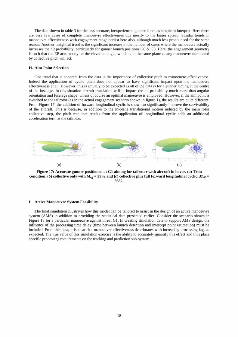
H. Aim-Point Selection
One trend that is apparent from the data is the importance of collective pitch to manoeuvre effectiveness.
Indeed the application of cyclic pitch does not appear to have significant impact upon the manoeuvre
effectiveness at all. However, this is actually to be expected as all of the data is for a gunner aiming at the centre
of the fuselage. In this situation aircraft translation will in impact the hit probability much more than angular
orientation and fuselage shape, unless of course an optimal manoeuvre is employed. However, if the aim point is
switched to the tailrotor (as in the actual engagement scenario shown in figure 1), the results are quite different.
From Figure 17, the addition of forward longitudinal cyclic is shown to significantly improve the survivability
of the aircraft. This is because, in addition to the in-plane translational motion induced by the main rotor
collective step, the pitch rate that results from the application of longitudinal cyclic adds an additional
acceleration term at the tailrotor.
(a) (b) (c)
Figure 17: Accurate gunner positioned at G1 aiming for tailrotor with aircraft in hover. (a) Trim
condition, (b) collective only with Meff = 29% and (c) collective plus full forward longitudinal cyclic, Meff =
93%.
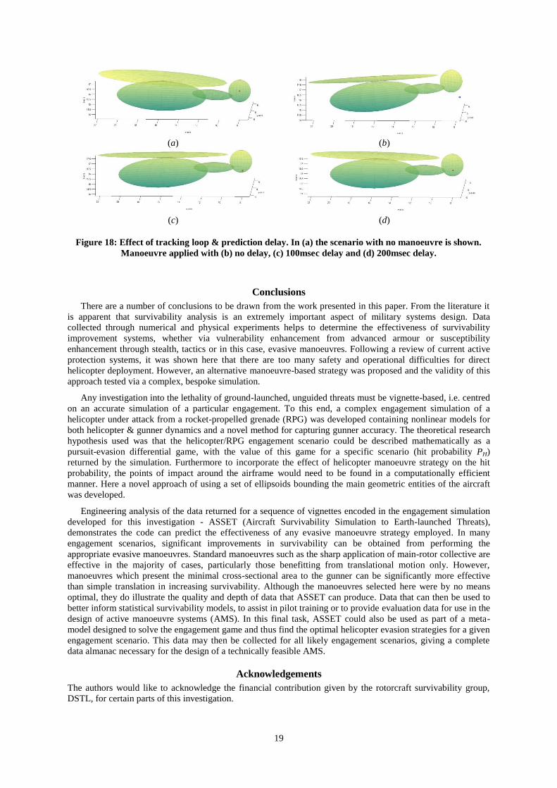
I. Active Manoeuvre System Feasibility
The final simulation illustrates how this model can be tailored to assist in the design of an active manoeuvre
system (AMS) in addition to providing the statistical data presented earlier. Consider the scenario shown in
Figure 18 for a particular manoeuvre against threat G1. In creating simulation data to support AMS design, the
influence of the processing time delay (time between launch detection and intercept point estimation) must be
included. From this data, it is clear that manoeuvre effectiveness deteriorates with increasing processing lag, as
expected. The true value of this simulation exercise is the ability to accurately quantify this effect and thus place
specific processing requirements on the tracking and prediction sub-system.
19
(a) (b)
(c) (d)
Figure 18: Effect of tracking loop & prediction delay. In (a) the scenario with no manoeuvre is shown.
Manoeuvre applied with (b) no delay, (c) 100msec delay and (d) 200msec delay.
Conclusions
There are a number of conclusions to be drawn from the work presented in this paper. From the literature it
is apparent that survivability analysis is an extremely important aspect of military systems design. Data
collected through numerical and physical experiments helps to determine the effectiveness of survivability
improvement systems, whether via vulnerability enhancement from advanced armour or susceptibility
enhancement through stealth, tactics or in this case, evasive manoeuvres. Following a review of current active
protection systems, it was shown here that there are too many safety and operational difficulties for direct
helicopter deployment. However, an alternative manoeuvre-based strategy was proposed and the validity of this
approach tested via a complex, bespoke simulation.
Any investigation into the lethality of ground-launched, unguided threats must be vignette-based, i.e. centred
on an accurate simulation of a particular engagement. To this end, a complex engagement simulation of a
helicopter under attack from a rocket-propelled grenade (RPG) was developed containing nonlinear models for
both helicopter & gunner dynamics and a novel method for capturing gunner accuracy. The theoretical research
hypothesis used was that the helicopter/RPG engagement scenario could be described mathematically as a
pursuit-evasion differential game, with the value of this game for a specific scenario (hit probability PH)
returned by the simulation. Furthermore to incorporate the effect of helicopter manoeuvre strategy on the hit
probability, the points of impact around the airframe would need to be found in a computationally efficient
manner. Here a novel approach of using a set of ellipsoids bounding the main geometric entities of the aircraft
was developed.
Engineering analysis of the data returned for a sequence of vignettes encoded in the engagement simulation
developed for this investigation - ASSET (Aircraft Survivability Simulation to Earth-launched Threats),
demonstrates the code can predict the effectiveness of any evasive manoeuvre strategy employed. In many
engagement scenarios, significant improvements in survivability can be obtained from performing the
appropriate evasive manoeuvres. Standard manoeuvres such as the sharp application of main-rotor collective are
effective in the majority of cases, particularly those benefitting from translational motion only. However,
manoeuvres which present the minimal cross-sectional area to the gunner can be significantly more effective
than simple translation in increasing survivability. Although the manoeuvres selected here were by no means
optimal, they do illustrate the quality and depth of data that ASSET can produce. Data that can then be used to
better inform statistical survivability models, to assist in pilot training or to provide evaluation data for use in the
design of active manoeuvre systems (AMS). In this final task, ASSET could also be used as part of a meta-
model designed to solve the engagement game and thus find the optimal helicopter evasion strategies for a given
engagement scenario. This data may then be collected for all likely engagement scenarios, giving a complete
data almanac necessary for the design of a technically feasible AMS.
Acknowledgements
The authors would like to acknowledge the financial contribution given by the rotorcraft survivability group,
DSTL, for certain parts of this investigation.
20
References
[1] Everett-Heath, E. J., Helicopters in Combat: The First Fifty Years, Arms and Armour Press, London,
1992, Chaps. 1,2.
[2] Law, N. G., "Integrated Helicopter Survivability," PhD Dissertation, Cranfield Defence & Security
Aeromechanical Systems Group, Cranfield University, 2011.
[3] Rodrigues, L. J., "Electronic Warfare: Army Special Operations Acquisition Strategy for Improved
Equipment is Sound," U.S. General Accounting Office, Washington DC, Rept. GAO/NSIAD-99-189,
1999.
[4] Loveless, A., "A Tough Old Bird - Surviving an Ambush in Helmand," Defence Helicopter, Vol. 28,
No. 3, 2009, pp. 22-23.
[5] O'Connell, P., "Assessment of Rocket Propelled Grenades (RPGs) Damage Effects on Rotorcraft,"
Aircraft Survivability, 2006, pp. 18-19.
[6] Ball, R. E., The Fundamentals of Aircraft Combat Survivability Analysis and Design, 2nd ed., AIAA
Education Series, AIAA, 2003, Chaps. 1,3,6.
[7] Couch, M. and Lindell, D., "Study on Rotorcraft Safety and Survivability," presented at the 66th
Annual Forum of the American Helicopter Society, Phoenix, AZ, 2010.
[8] Anderson, D., et al., "Fast Model Predictive Control of the Nadir Singularity in Electro-Optic
Systems," Journal of Guidance, Control, and Dynamics, Vol. 32, No. 2, 2009, pp. 626-632.
doi:10.2514/1.30762
[9] "TRADOC Bulletin 3u: Soviet RPG-7 Antitank Grenade Launcher," US Army Training and Doctrine
Command, 1976.
[10] Koegler, J., et al., "Next Generation Air Defense Artillery Modeling and Simulation," Aircraft
Survivability, 2009, pp. 14-17.
[11] Anderson, D. and Thomson, D. G., "Improving rotorcraft survivability to RPG attack using inverse
methods," in SPIE Europe Defence & Security Conference, Berlin, 2009, p. 74830M.
doi:10.1117/12.832298
[12] Anderson, D. and Carson, K., "Integrated variable-fidelity modelling for remote sensing system
design," in SPIE Europe Defence & Security Conference, Berlin, 2009, pp. 74830O-74830O-9.
doi:10.1117/12.832633
[13] Anderson, D. and Thomson, D. G., "Simulating effectiveness of helicopter evasive manoeuvres to RPG
attack," in SPIE Defense, Security & Sensing Conference, Orlando, USA, 2010.
[14] Stewart, R., "RPG Encounter Modeling," SURVIAC Bulletin, Vol. 27, No. 1, 2012.
[15] LaValle, S. M., Planning Algorithms, Cambridge University Press, 2006, Chap. 6.
[16] Sastry, S., Nonlinear Systems: Analysis, Stability & Control, Interdisciplinary Applied Mathematics,
Springer, New York, 1999, Chaps. 2,3.
[17] Phillips, W. E., Mechanics of Flight, John Wiley & Sons, Inc., New Jersey, 2004, pp. 34-45.
[18] Pettit, R. L., Homer, M.L., "An Autonomous Threat Evasion Response Algorithm for Unmanned Air
Vehicles During Low Altitude Flight," in AIAA 1st Intelligent Systems Technical Conference, Chicago,
Illinois, 2004.
[19] Isaacs, R., Differential Games, Wiley, New York, 1965, Chaps. 1,3.
[20] Thomson, D. G., "Development of a Generic Helicopter Model for Application to Inverse Simulation,"
University of Glasgow, Department of Aerospace Engineering, Internal report No. 9216, Glasgow,
UK., 1992.
[21] Thomson, D. G. and Bradley, R., "Inverse Simulation as a Tool for Flight Dynamics Research,"
Progress in Aerospace Sciences, Vol. 42, No. 3, 1998, pp. 174-210.
[22] Anderson, D., "Modification of a Generalised Inverse Simulation Technique for Rotorcraft Flight,"
Proceedings Of The Institution Of Mechanical Engineers, Part G: Journal Of Aerospace Engineering,
Vol. 217, No. 2, 2003, pp. 61-73.
doi:10.1243/095441003765208727
[23] Padfield, G. D., Helicopter Flight Dynamics, Wiley Blackwell, 1996, Chap. 3.
[24] Thomson, D. G. and Bradley, R., "The Principles and Practical Application of Helicopter Inverse
Simulation," Simulation Practice and Theory, International Journal of the Federation of European
Simulation Societies, Vol. 6, No. 1, 1998, pp. 47-70.
[25] Gregory, J., Game Engine Architecture, Taylor & Francis, Boca Raton, FL., 2009, Chaps. 2,3.
[26] Groves, P. D., Principles of GNSS, Inertial and Multisensor Integrated Navigation Systems, GNSS
Technology and Applications Series, Artech House, Boston, 2008, pp. 55-78.
[27] Anderson, D. and Thomson, D. G., "Risk Assessment to Helicopter Threats in Current Operational
Scenarios," Aerospace Sciences Research Division, University of Glasgow, 2011.