Embed Size (px)
Citation preview
PIERS ONLINE, VOL. 3, NO. 6, 2007 916
Analysis on the Shielding Effect of the Power Transformer Tank
Duo Chen, Haiyu Yu, and Jiansheng Yuan
State Key Lab of Power Systems, Department of Electrical EngineeringTsinghua University, Beijing 100084, China
Abstract— The MV/LV transformer without a tank in the underground substation can pro-duce remarkable interference with the computer Cathode-Ray Tube (CRT) displayers above theground, because of the generated power frequency magnetic field. To resolve such problem, atank with high conductivity or/and high permeability is needed to enclose the transformer. Toevaluate the shielding effectiveness, the finite element method is adopted to calculate the leakagemagnetic field outside the transformer tank with different materials. The calculated results showthat the steel tank is able to achieve an enormous shielding effectiveness.
DOI: 10.2529/PIERS060908000140
1. INTRODUCTION
The shielding effectiveness of the power transformer is a very important target in transformerdesign. When the transformer is located near to the computer Cathode-Ray Tube (CRT), evenvery small power frequency magnetic field intensity can generate remarkable interference. Accordingto the IEC 61000-4-8 (1993) [1], the environment of power frequency magnetic field is defined asfive levels based on its magnitude. Different electronic devices can work normally at differentlevel. According to our test, the CRT can not normally display or the screen will dither obviously,when the background magnetic field intensity is greater than 1A/m (or the magnetic flux densityis greater than 1.256µT)—worse than the first level environment [1]. If such sensitive electronicdevices locate just above the underground substation, they will be interfered and can not worknormally.
Usually, the dry transformers are employed in such MV/LV (Middle voltage/Lower voltage)substations. Therefore, from the engineering point of view, it is not necessary to set any tank tothe transformers. However, from the electromagnetic inference point of view, a tank of metal orferromagnetic material must be set as the electromagnetic shielding. Due to the high conductivityof metal materials, the induced eddy current in the metal tank is large, which can reduce the leakagefield outside the tank. Due to the high permeability of ferromagnetic material, the magnetic fieldis bounded inside the tank, so that the field outside the tank is reduced. By considering such twokinds of behavior together for ordinary materials (e. g., steel), the analysis and the design of thetank become complex. It is almost impossible to calculate the leakage field outside the tank byanalytical solutions. In contrast, the numerical computation method must be used to obtain theresult of such complex problem.
In this paper, aluminum, steel and an assumptive material with zero-conductivity and a highrelative permeability of 10000 are chosen to analyze and compare their shielding effect. The three-dimensional finite element method is adopted to calculate the leakage field outside the transformertank. The paper is organized as follows: Section 2 introduces the parameter of a MV/LV trans-former and its three-dimensional finite element model. Section 3 analyzes the simulation resultsand compares the shielding effectiveness of tanks with different materials.
2. THE TRANSFORMER AND ITS FINITE ELEMENT MODEL
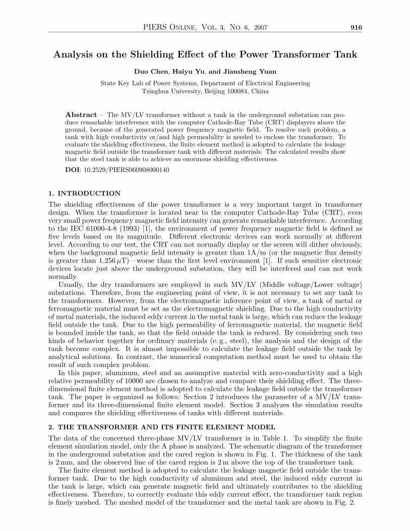
The data of the concerned three-phase MV/LV transformer is in Table 1. To simplify the finiteelement simulation model, only the A phase is analyzed. The schematic diagram of the transformerin the underground substation and the cared region is shown in Fig. 1. The thickness of the tankis 2 mm, and the observed line of the cared region is 2 m above the top of the transformer tank.
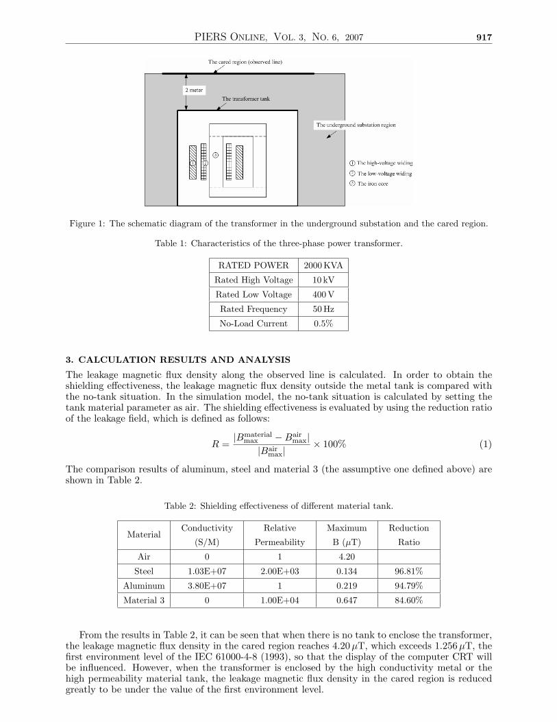
The finite element method is adopted to calculate the leakage magnetic field outside the trans-former tank. Due to the high conductivity of aluminum and steel, the induced eddy current inthe tank is large, which can generate magnetic field and ultimately contributes to the shieldingeffectiveness. Therefore, to correctly evaluate this eddy current effect, the transformer tank regionis finely meshed. The meshed model of the transformer and the metal tank are shown in Fig. 2.
PIERS ONLINE, VOL. 3, NO. 6, 2007 917
Figure 1: The schematic diagram of the transformer in the underground substation and the cared region.
Table 1: Characteristics of the three-phase power transformer.
RATED POWER 2000KVA
Rated High Voltage 10 kV
Rated Low Voltage 400V
Rated Frequency 50Hz
No-Load Current 0.5%
3. CALCULATION RESULTS AND ANALYSIS
The leakage magnetic flux density along the observed line is calculated. In order to obtain theshielding effectiveness, the leakage magnetic flux density outside the metal tank is compared withthe no-tank situation. In the simulation model, the no-tank situation is calculated by setting thetank material parameter as air. The shielding effectiveness is evaluated by using the reduction ratioof the leakage field, which is defined as follows:
R =|Bmaterial
max −Bairmax|
|Bairmax|
× 100% (1)
The comparison results of aluminum, steel and material 3 (the assumptive one defined above) areshown in Table 2.
Table 2: Shielding effectiveness of different material tank.
MaterialConductivity
(S/M)
Relative
Permeability
Maximum
B (µT)
Reduction
Ratio
Air 0 1 4.20
Steel 1.03E+07 2.00E+03 0.134 96.81%
Aluminum 3.80E+07 1 0.219 94.79%
Material 3 0 1.00E+04 0.647 84.60%
From the results in Table 2, it can be seen that when there is no tank to enclose the transformer,the leakage magnetic flux density in the cared region reaches 4.20µT, which exceeds 1.256 µT, thefirst environment level of the IEC 61000-4-8 (1993), so that the display of the computer CRT willbe influenced. However, when the transformer is enclosed by the high conductivity metal or thehigh permeability material tank, the leakage magnetic flux density in the cared region is reducedgreatly to be under the value of the first environment level.
PIERS ONLINE, VOL. 3, NO. 6, 2007 918
(a) (b)
Figure 2: 3D finite element model of the transformer: (a) the meshed model of the core and windings, (b)the meshed model of the transformer tank.
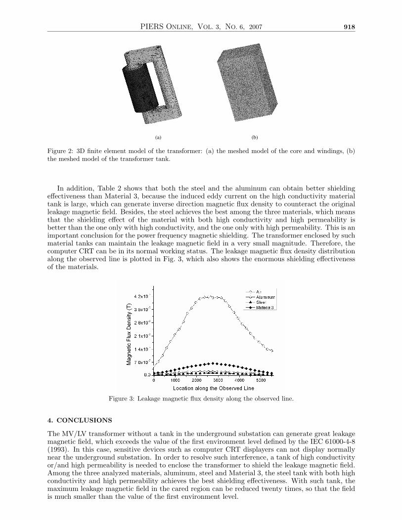
In addition, Table 2 shows that both the steel and the aluminum can obtain better shieldingeffectiveness than Material 3, because the induced eddy current on the high conductivity materialtank is large, which can generate inverse direction magnetic flux density to counteract the originalleakage magnetic field. Besides, the steel achieves the best among the three materials, which meansthat the shielding effect of the material with both high conductivity and high permeability isbetter than the one only with high conductivity, and the one only with high permeability. This is animportant conclusion for the power frequency magnetic shielding. The transformer enclosed by suchmaterial tanks can maintain the leakage magnetic field in a very small magnitude. Therefore, thecomputer CRT can be in its normal working status. The leakage magnetic flux density distributionalong the observed line is plotted in Fig. 3, which also shows the enormous shielding effectivenessof the materials.
Figure 3: Leakage magnetic flux density along the observed line.
4. CONCLUSIONS
The MV/LV transformer without a tank in the underground substation can generate great leakagemagnetic field, which exceeds the value of the first environment level defined by the IEC 61000-4-8(1993). In this case, sensitive devices such as computer CRT displayers can not display normallynear the underground substation. In order to resolve such interference, a tank of high conductivityor/and high permeability is needed to enclose the transformer to shield the leakage magnetic field.Among the three analyzed materials, aluminum, steel and Material 3, the steel tank with both highconductivity and high permeability achieves the best shielding effectiveness. With such tank, themaximum leakage magnetic field in the cared region can be reduced twenty times, so that the fieldis much smaller than the value of the first environment level.

PIERS ONLINE, VOL. 3, NO. 6, 2007 919
ACKNOWLEDGMENT
This work was supported by the National Natural Science Foundation of China (No. 50677028),SRFDP (No. 20050003007) and Tsinghua Basic Research Foundation.
REFERENCES
1. IEC 61000-4-8, “Testing and measurement techniques-Section 8: Power frequency magneticfield test,” Electromagnetic Compatibility (EMC)-Part 4, Basic EMC Publication, 1993.


![Physics and Modelling of Nanocrystalline Silicon Thin-Film ... · FET Field-efiect Transistor - A transistor which operates via the fleld-efiect, modulating ... switch[2]1. Intrinsica-Si:Hsatisflesthisrequirement](https://img.pdfslide.us/doc/110x75/5f7ed93f907945508032be14/physics-and-modelling-of-nanocrystalline-silicon-thin-film-fet-field-eiect.jpg)