Embed Size (px)
Citation preview

Analysis of rock cutting process with a blunt PDCcutter under different wear flat inclination angles
Iman Rostamsowlata,∗, Babak Akbarib, Brian Evansc
aDeep Exploration Technologies CRC, Department of Petroleum Engineering, CurtinUniversity, Kensington, WA 6151, Australia
bCraft and Hawkins Department of Petroleum Engineering, Louisiana State University, OldForestry Building #125, Baton Rouge, LA 70803, USA
cDepartment of Petroleum Engineering, Curtin University, Australia
Abstract
It is generally accepted that drilling with drag bits (Polycrystalline Diamond
Compact bits) simultaneously consists of “pure cutting” and “frictional contact”
processes. To date, the mechanics of rock cutting have been mostly based on
the assumption that these two processes are fully independent as the influence
of wear flat inclination angle (β) with respect to the cutter velocity vector (v)
on the frictional contact force is often not accounted for. The specific aim
of this study is to determine the effect of wear flat inclination angle on the
frictional force acting on the wear flat surface of a single blunt cutter over a wide
range of depths of cut (d). For this purpose, an extensive and comprehensive
set of cutting experiments was performed on two sedimentary rock samples (a
limestone and a sandstone) using a state-of-the-art rock cutting equipment and
a unique cutter holder. The results show that the normal contact stress (σ)
at the wear flat-rock interface (and therefore the normal frictional force acting
on the wear flat) is dependent on the depth of cut within the elastoplastic and
particularly plastic regimes of frictional contact; however, the contact stress is
invariant with depth of cut within the elastic regime. Further investigations
indicate that the assumption that the force acting on the wear flat surface of
∗Corresponding author:Email address: [email protected],
[email protected] (Iman Rostamsowlat)
Preprint submitted to Journal of Petroleum Science and Engineering May 24, 2018

a blunt cutter is independent of the cutting process taking place ahead of the
cutter is not valid in particular, for the large values of inclination angles.
Keywords: Rock cutting, Contact stress, Wear flat inclination angle, Depth of
cut, Pure cutting process, Frictional contact process
List of symbols
F Total force acting on the cutter
Fc, Ff Total cutting and frictional contact forces
Fcn, Fcs Normal and tangential components of the total cutting force
Ffn, Ffs Normal and tangential components of the total frictional contact force
˜Ffn, Ffs Projected components of the contact force components
d Depth of cut
Ac Cross-sectional area of groove traced by cutter
Af Wear flat area
ω Width of cutter
q Uniaxial compressive strength of the rock material
ζ Ratio of normal component to tangential component of cutting force
ε Intrinsic specific energy
θ Back rake angle
θ∗ Initial back rake angle
∆θ∗ Relative increment of back rake angle
ψ Interfacial friction angle
v Horizontal cutting tool velocity
µ Friction coefficient
σ Normal contact stress
` Length of wear flat surface
β Inclination angle of wear flat with respect to velocity vector
E∗ Plane strain elastic modulus of the rock sample∏Scaled contact stress
η Dimensionless number
2

χ Chamfer angle
∆z Relative vertical displacement of spindle
1. Introduction
Better understanding of rock cutting or fragmenting has been one of the main
objectives of drilling research since the 1950s and has received increased at-
tention in both theoretical and experimental research areas. Drilling has been
performed mainly using roller cone bits, until the introduction of PDC (Poly-5
crystalline Diamond Compact) drag bits in the late 1970’s [1–4]. The application
of this new material reduced the drilling costs by improving the efficiency (their
high rate of penetration ROP) and the lifetime of the bits. Due to the shear cut-
ting mechanism of the PDC drill bits, they drill several times faster than roller
cone bits [5, 6]. A PDC bit consists of a matrix (tungsten carbide metallurgi-10
cally bonded with a metallic binder) or steel body that is covered with inserts
often referred to as PDC cutters which are made of a thin layer of synthetic
polycrystalline diamond bonded on a tungsten carbide substrate. A PDC drag
bit is actually composed of a multiplicity of individual PDC cutters mounted
at the surface of a bit body. Therefore, a study of the drilling response of PDC15
bits can be done by establishing the cutting response of an individual cutter
[7–11].
It is commonly admitted in the literature [12–17] that the cutting action of
a blunt (worn) cutter or drag bit can be divided into two independent processes:
(i) a pure cutting action in front of the cutting face, and (ii) a frictional pro-20
cess mobilized across the wear flat surface. To date, a large body of research
studies (both numerical simulations and experimental investigations) have been
mainly based on this main assumption that these two processes (pure cutting
and frictional contact) are uncoupled. In other words, the total force acting
on a single blunt cutter or drag bit can be simply written as the sum of two25
independent forces, Fc and Ff which coexist and are associated with the pure
cutting (subscript c) and frictional contact processes (subscript f), respectively
3
(Eq. 1).
F = Fc + Ff (1)
On the other hand, in the overwhelming majority of research studies on
rock cutting, it is assumed that the contact force acting on the wear flat surface30
(or eventually the normal contact stress (σ) mobilized across the wear flat-rock
interface) is independent of both the inclination angle β (defined as the angle
between the wear flat surface and the linear velocity vector of the cutter v)
and the rate of penetration ROP (defined as the depth of cur per revolution
which is equivalent to the depth of cut (d) for a single cutter [18]), see Fig.35
1. Little research [19–22] has been reported, however, on the predominant
influence of the inclination angle (β) on the normal contact stress at wear flat-
rock interface. Nonetheless, to the best knowledge of the authors, no reliable
and robust study has been devoted to review the validation of the independence
between the cutting and frictional processes (proposed by several authors) with40
a consideration of the variations of wear flat inclination angle (β) at different
cutting depths (d).
The main objective of this paper is to investigate experimentally, how the
inclination angle affects the normal contact stress at the wear flat-rock interface
of a single blunt cutter tracing a groove on the surface of a rock sample at dif-45
ferent depths of cut (or ROP). In addition, the main assumption of the bit-rock
interaction model, indicating the independence between the cutting and friction
processes, is also reviewed and discussed with consideration of the inclination
angle. To this end, an extensive campaign of cutting tests equivalent to the ex-
cavation process (but under dry conditions) with different wear flat inclination50
angles (β), different depths of cut (d), and two rock materials was conducted
using a state-of-the-art scratching device (Wombat) and a novel cutter holder
allowing for precise adjustment of the angle of inclination (β) by steps of 0.10◦.
4

θ
θ
z
v
t
n
sk
d
v
Rock
sn
dß
k 𝑧
(a)
(b)
Figure 1: (a) 3D drawing of a PDC bit (updated from [23]), and (b) sketchesof a worn cutter tracing a groove of depth d on the bottom hole. The angleβ is the angle between the cutter wear surface and the cutter linear velocity(v).
In this paper, we first review the models of rock cutting, with consideration
given to the ductile mode of failure [24]. Then, the phenomenological model of55
rock cutting [14] commonly used in rock cutting, is derived. We then describe
the experimental setup, equipment specifications, and the physical properties of
the rock materials used in this study. Finally, we provide compelling evidence
that the frictional force is a function of depth of cut and that the “pure cutting”
and “frictional contact” processes are not fully two independent processes.60
2. Models of cutting process with a single cutter
Rock cutting or rock scratching can be described as the shaving or machining
of a layer of rock from a free surface with the tool moving parallel to the free
surface. The first cutting models were inspired from the metal cutting model
presented by Merchant in 1944 [25, 26]. Merchant’s semi-empirical model was65
5

based on a Mohr-Coulomb plasticity criterion and force equilibrium of a single
shear plane in orthogonal cutting action. The application of Merchant’s model
was limited to rock cutting as it was based on the assumption of a perfectly
sharp cutter while, in practice, the cutters develop a wear flat which affects
the force on the cutter. Subsequently, other authors [27–31] have proposed the70
Merchant based models.
Nishimatsu [29] was one of the first to offer a model suitable for cutting
rocks. His study has inspired other researchers to develop models based on
different concepts of mechanical destruction of the rock. Nishimatsu’s model
was more applicable for chip formations and discontinuous rock cutting but this75
model fails for the ductile mode of failure. Another limitation of Nishimatsu’s
model was that the effect of wear flat was not accounted for [17, 29, 32, 33].
Lebrun [30], extending Nishimatsu’s theory, developed a three dimensional
model for the failure of the rock subjected to the action of a cutting tool. Lebrun
proposed that the cutting force and the depth of cut are linearly related, with80
a coefficient of proportionality that depends on the width, wear and rake angle
of the cutter. He also stated that the cutting and normal forces are linearly
related, with a proportionality coefficient that depends mainly on the degree of
wear. Cheatham [34] has shown that the cutter forces are functions of cutting
area and rock shear strength. This researcher has also shown that the cutter85
forces are independent of the particular cutter shape and can be predicted with
Merchant’s metal cutting model.
The limitation of many models available in the literature is that the effect
of wear flat is often not accounted for. Therefore, a model of rock cutting was
then developed by Glowka [13, 32] while the frictional contact between the cutter90
and free surface of the rock was taken into account. He analyzed the effect of
temperature on wear and also studied the effect of wear on the efficiency of the
cutting tool.
A phenomenological model proposed by Detournay & Defourny [14] (referred
to as the “DD-model”) was based on the suggestion of Fairhurst and Lacabanne95
[16] that the force acting on a single cutter is governed by the coexistence of
6

two independent processes: the “pure cutting” process in front of the cutting
face and the “frictional contact” mobilized across the wear flat surface. This
model was validated against experimental results published by Glowka (1987)
and developed to describe the rock cutting process under conditions when the100
mode of rock failure induced by the cutter can be described as plastic. This
is typically the failure mode (ductile mode of failure) observed in sedimentary
rocks at shallow depth of cut (typically less than 1 mm) [14, 24, 35–38]. Since
then, Almenara (1992), Samiselo(1992), Lasserre (1994) and Adachi (1996) also
provided experimental support to the DD-model.105
The DD-model is mainly based on the following assumptions:
1. the cutting process can be decomposed into two independent processes:
the “pure cutting” process and the “frictional contact” at the wear flat-
rock interface,
2. the force acting on the cutting face is proportional to the cross-sectional110
area of the groove (Ac), and
3. the total force (frictional force) acting on the wear flat-rock interface of a
blunt cutter is independent from the depth of cut (d) and its normal and
tangential components are related by a frictional law.
3. Pure cutting/frictional contact115
As mentioned in the section 2, Detournay and Defourny (1992) proposed a
phenomenological model (DD-model) for the forces acting on a single cutter
and/or PDC drag bit which were compared to the experimental data. The
model dealt with the pure cutting (sharp cutter) and the frictional contact
(blunt cutter), separately [14]. In rock cutting, the mode of failure shifts from120
ductile (plastic failure) to brittle (propagation of fractures) with an increase of
depth of cut [35–38], and the main focus of the DD-model is only on the ductile
mode of the failure taking place at the shallow depths of cut [24, 35].
7

First, a perfectly sharp cutter is considered in Fig. 2a. According to the
DD-model, for the sharp cutter and before the formation of a wear flat at the125
cutter tip, the total force acting on the cutter represents only the cutting force
(F = Fc) [8]. In other words, the force acting on the cutting face is only uti-
lized in cutting rocks. The cutter traces a groove at a constant depth of cut
(d) and moves in a horizontal direction, as depicted by the velocity vector (v).
The cutting process, under kinematic control, is assumed to be steady state.130
Therefore, instead of considering peak forces, the model takes into account the
forces “averaged over a distance, large compared to the depth of cut” [24]. Con-
sidering the second assumption of the DD-model in section 2, the total cutting
force (Fc) can be decomposed into components; normal (Fcn) and tangential
(Fcs) to the rock surface and can be written as:135
Fcn = ζεAc
Fcs = εAc
(2)
where ε is the intrinsic specific energy (minimum energy to remove a unit volume
of the rock with the dimension of stress MPa [43]) that is found well correlated
with the uniaxial compressive strength of the rock (q) [24, 44–47], Ac is the
cross-sectional area of the groove traced by the cutter (which for a rectangular
shaped cutter, is equal to cutter width (ω) multiplied by the depth of cut (d))140
and the number ζ (ζ = tan(θ + ψ) = Fcn
Fcs) can be simply interpreted as the
ratio of normal to tangential components of the cutting force. Here, ψ is the
interfacial friction angle and θ is the back rake angle (positive when inclined
forward) which is defined as the angle between the normal to the cutting face
(k) and the velocity vector (v).145
8
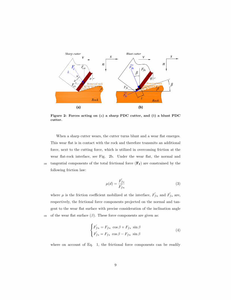
(a) (b)
Figure 2: Forces acting on (a) a sharp PDC cutter, and (b) a blunt PDCcutter.
When a sharp cutter wears, the cutter turns blunt and a wear flat emerges.
This wear flat is in contact with the rock and therefore transmits an additional
force, next to the cutting force, which is utilized in overcoming friction at the
wear flat-rock interface, see Fig. 2b. Under the wear flat, the normal and
tangential components of the total frictional force (Ff ) are constrained by the150
following friction law:
µ(d) =Ffs˜Ffn
(3)
where µ is the friction coefficient mobilized at the interface, ˜Ffn and Ffs are,
respectively, the frictional force components projected on the normal and tan-
gent to the wear flat surface with precise consideration of the inclination angle
of the wear flat surface (β). These force components are given as:155 ˜Ffn = Ffn cosβ + Ffs sinβ
Ffs = Ffs cosβ − Ffn sinβ(4)
where on account of Eq. 1, the frictional force components can be readily
9

obtained by: Ffs(d, θ) = Fs(d, θ)− Fcs(d, θ)
Ffn(d, θ) = Fn(d, θ)− Fcn(d, θ)(5)
and Ff (d, θ) is the force measured on a blunt cutter at a given depth of cut
(d) and at a given back rake angle (θ), and Fc(d, θ) is the force measured on a
sharp cutter for the same depth of cut and back rake angle. It is important to160
reiterate that the normal Fcn(d, θ) and tangential Fcs(d, θ) components of the
pure cutting force are measured from tests performed with a sharp cutter [48].
In addition, the normal contact stress mobilized at the wear flat-rock inter-
face reads as:
σ(d) =Ffn cosβ + Ffs sinβ
ω`=
˜FfnAf
(6)
where σ is the contact stress mobilized across the wear flat (which is of the165
order of the uniaxial compressive strength q [21, 39, 41, 42, 49–51]) and Af is
the wear flat area (Af = ω× ` for a rectangular shaped cutter with ` being the
length of wear flat surface, see Fig. 2b).
Experimental results reveal three distinct phases in the cutting response of
a worn cutter (or drilling response of a drag bit) with respect to the depth of170
cut (d) [19, 49–52], see Fig. 3. At shallow depth of cut (phase I), it is assumed
that the two contacting surfaces (the cutter wear flat and the rock surfaces)
are not entirely conforming, and increase in depth of cut leads to an increase
in both the cutting force associated with the pure cutting process but also in
the effective contact area (Af ), up to a critical depth of cut (d < d∗). In175
phase II (d∗ ≤ d ≤ d∗∗), the effective contact area has reached a limit value
(Af = Af∗), and the incremental drilling-cutting response is governed by the
pure cutting process [51]. On a drill bit, phase III is marked by the occurrence
of an additional contact between the rock and bit body as an excess of cuttings
is not efficiently flushed away from the bit face.180
10

𝑑∗∗ 𝑑∗ 𝑑
𝐴𝑓
𝐴𝑓∗
Phase I Phase II Phase III
Figure 3: Conceptual Evolution of contact area (Af) with depth of cut (d)for a blunt cutter.
The response of a blunt cutter in a force-depth of cut relationship is illus-
trated in Fig. 4. The extent of phase I is controlled by the size of the wear
surface and the angle β [21]; in phase II, the response is parallel to the response
of a sharp cutter [14, 39, 42, 50].
11

𝑑
𝐹
𝑆ℎ𝑎𝑟𝑝 𝑐𝑢𝑡𝑡𝑒𝑟
𝑑∗
𝐵𝑙𝑢𝑛𝑡 𝑐𝑢𝑡𝑡𝑒𝑟
𝑃ℎ𝑎𝑠𝑒 𝐼 𝑃ℎ𝑎𝑠𝑒 𝐼𝐼
Figure 4: Conceptual plot of force against depth of cut for both a sharpand blunt cutters.
Furthermore, numerical [20] and experimental studies [21, 22, 48] with a185
single blunt PDC cutter consistently indicate that the scaled contact stress
(∏
= σq ) at the wear flat-rock interface is predominantly controlled by one
dimensionless number η = E∗ tan βq where E∗ is the plane strain elastic modulus
of the rock sample. As a consequence, three regimes of frictional contact exist
(identified as elastic, elastoplastic and fully plastic) depending on the value of β190
(or eventually the dimensionless number η), see Fig. 5. More recently, [21, 22], a
comprehensive set of cutting experiments was carried out on Tuffeau limestone
and Mountain Gold sandstone using a single blunt PDC cutter to confirm the
existence and location of these three regimes of frictional contact. Experimental
observations show that the elastic (βe) and plastic (βp) limits sit at about the195
same angle for both rock samples (βe ' 2.40◦ and βp ' 7.40◦), as shown in Fig.
5. This dependency of the contact stress on the angle β should be accounted
for when modeling the dynamic response (torsional or axial vibrations) of PDC
drill bits [53–62].
12

0
1
2
3
4
5
-5 -3 -1 1 3 5 7 9 11 13 15 17 19
Mountain Gold
Tuffeau
𝛽°
∏𝑬𝒍𝒂𝒔𝒕𝒊𝒄𝒓𝒆𝒈𝒊𝒎𝒆
𝑬𝒍𝒂𝒔𝒕𝒐𝒑𝒍𝒂𝒔𝒕𝒊𝒄𝒓𝒆𝒈𝒊𝒎𝒆
𝑷𝒍𝒂𝒔𝒕𝒊𝒄𝒓𝒆𝒈𝒊𝒎𝒆
𝜷𝒆 𝜷𝒑
Figure 5: Scaled contact stress (∏
) versus inclination angle (β) at d=0.70mm. Tests conducted on Tuffeau limestone and Mountain Gold sandstone[21, 22].
4. Full scale drilling case200
It is generally accepted that different types of wear mechanism are in effect
during the process of drilling including the steady wear as a result of abrasion
and other wear modes, such as chipping, mostly caused by drilling dynamics.
The wear flat studied in this work is mostly caused by the former mode of
wear which erodes the cutter due to continuous frictional contact with the rock205
abrasive minerals. Normally, in the absence of drilling dynamic phenomena,
this should be the predominant type of wear observed on a PDC cutter.
Limited information exists within the current literature relating the inclina-
tion angle (β) to drilling parameters. Ersoy and Waller [63] reported that soft
formations tend to wear the cutter at a higher inclination angle compared to210
hard/brittle formations. Remarks have been made by Zijsling and Djurre [64]
that can lead to a general understanding of the range of β values expected in
13

practice. The document states that (supported by claimed field observations)
the wear flat tends to create an angle of between 10◦ to 15◦ with the hole
bottom.215
If the observations stated above are accepted, results of this work may have
immediate implications in hard/brittle rock drilling; among any other future
applications. Glowka [65] observed that a PDC cutter “thermally accelerated
wear” in hard rock drilling instigates when [in effect] the scaled contact stress
(∏
= σq ) is near or above 1.0. Therefore, to avoid this accelerated mode of wear220
and to prolong the bit run, it may be desirable to stay within the elastic regime
of frictional contact for the rock types presented in Fig. 5 and Fig. 6.
0
1
2
3
4
5
6
-5 -3 -1 1 3 5 7 9 11 13 15 17
d=0.06 mm d=0.09 mm
d=0.15 mm d=0.20 mm
d=0.30 mm d=0.50 mm
d=0.60 mm d=0.70 mm
d=0.80 mm d=0.90 mm
d=1 mm
𝛽°
∏
Figure 6: Scaled contact stress versus inclination angle at different depthsof cut. Tests conducted on Mountain Gold sandstone [21, 48].
The inclination between the wear surface and the cutter velocity vector is
controlled by the location of the cutter along the bit profile (in particular the
radial distance (R) with respect to the bit axis of rotation), the rate of penetra-225
14

tionon, and angular velocity (rotary speed). As a numerical example, consider
drilling into a hard rock formation with an 834 inch PDC bit that has already
developed some wear flat on the cutters. Further, for example, let us assume
that the magnitude of∏
is near or less than 1.0 at β < 2◦ for this rock type.
Under the assumption that a wear flat has formed parallel to the rock surface230
(or in other words, perpendicular to drill-bit axis), the angle β is given by:
β ≈ tan(β) =ROP. cos γ
5N.2πR(7)
in which, ROP is rate of penetration in ft/hr, N is rotary speed in rotation
per minute, and R is the radius from the bit center axis in inches, and γ is
the angle that the normal to bit profile makes with the bit axis. For the sake
of simplicity, we only consider cutters on the nose area (assuming R ≈ 2.56235
inch) for which γ ≈ 0◦, and therefore cos(γ) ≈ 1. Applying these parameters
to the equation results in the condition of N > ROP2.74 in order to have β < 2◦
and minimize thermally accelerated wear. In other words, for instance, rotary
speeds of less than 15 RPM while drilling at 40 ft/hr are not advisable in terms
of cutter wear. Although this numerical example may not be close enough to240
normal drilling parameters in the field to be of a concern, for formations with
lower critical angles or certain bit profiles with lower angle cones, the minimum
rotary speed may be much higher. Even in this same example, assuming a cone
angle of 30◦ for this bit, for the cutter(s) at 0.50 inch radius, we should have
N > ROP0.63 before the cutter acceleration wear starts; i.e. the minimum rotary245
speed at 40 ft/hr would be 64 RPM.
This application example should be generic enough to be utilized in finding
the inclination angle (β) for given conditions (and cutters). However, the con-
cept of limiting the inclination angle to a given range is only interpreted from
the results presented here and is only applicable for the range of parameters250
discussed here (including depth of cut), see Fig .6. Although one can anticipate
similar rocks and/or operating conditions; no claim is made herein for such cir-
cumstances. The available data for several other rock types [21, 48], however,
15

show similar behavior to that of Fig. 6; but are not included for briefness.
5. Experimental setup255
5.1. Scratching device and cutter holder
The cutting apparatus used for the cutting tests is called the “Wombat”1 ma-
chine which was designated to scratch rocks (using either a single blunt or a
single sharp cutter) by tracing a groove on the rock surface (Fig. 7). The
Wombat is a kinematically controlled apparatus, i.e. cutting tests are carried260
out under controlled depth of cut (d) with a predetermined constant horizontal
velocity (v = 4 mms ) along the entire cut, while the tangential (Fs) and normal
(Fn) components of the total force acting on the cutter are recorded separately
with a precision less than 1 N over a range of 0 to ±3500 N. Note that all cutting
tests in this study were based on the standard procedure explained in several265
references such as [21, 24, 66].
1This machine is housed in the Rock Mechanics Testing Laboratory, CSIRO, Perth, Aus-tralia.
16

Load cell
𝑆 𝑛
𝑡
Cutting tool
Load cell
Rotating wheel
Vertical slide
Carriage
tower
Horizontal
bed
Clamp
Load cell
Holder
Figure 7: The rock cutting machine.
A unique cutter holder was designed (using AutoCad 2015) and manufac-
tured to adjust the back rake angle of the cutter θ (and therefore the inclination
angle β) by steps of 0.10◦ [21, 22]. The main mechanical parts of this novel
cutter holder are shown in Fig. 8.270
17

Cutting
tool
High tensile screw
Micrometer
Spring
Nut
Fixed body High tensile
screw
Cutter seat
Flat
surface
𝑳 = 𝟏𝟏𝟒. 𝟒𝟗 mm
Δ𝜃∗ Adjustable arm
Figure 8: Schematic of the new cutter holder with fine adjustable inclina-tion angle.
As the blunt cutter is mounted on the cutter seat of the cutter holder with
a forward inclination (θ ≥ 0◦), the back rake angle of the cutter is first set to
an initial back rake angle (θ∗) and then incrementally increased by step of ∆θ∗
to reach the desired value of back rake angle θ (θ = θ∗ + ∆θ∗). Therefore, the
inclination angle of wear flat surface (Fig. 9) is derived by:275
β = χ− θ∗ −∆θ∗ (8)
where χ is the chamfer angle of the blunt cutter (and is a constant value for a
given blunt cutter and defined as the angle between the wear flat surface and
18

the direction of velocity vector when θ = 0◦2), see Fig. 9a, and ∆θ∗ can be
written as:
∆θ∗ = arcsin(∆z
L) (9)
Here, ∆z is the vertical displacement of the spindle of the micrometer and L is280
the radius of rotation, see Fig. 8. Note that the procedure and validation of the
method of measuring β is well described in Refs. [21, 22, 48].
(a) (b)
Figure 9: Definition of (a) the chamfer angle χ, and (b) the inclination angleβ between the wear flat surface of a blunt PDC cutter and the velocityvector (v).
5.2. Cutters specifications
Two rectangular shaped PDC cutters (one sharp and one blunt) were used in
this research with a width of 10 mm (ω = 10 mm). Note that the wear flat285
surface of a blunt cutter is precisely machined by grinding an originally sharp
cutter. The main geometrical properties of both the sharp and blunt cutters
used for cutting tests are presented in Table 1. In order to measure the length
of a wear flat (`) and the chamfer angle (χ), as schematically shown in Fig. 9, a
high resolution optical microscope (model AxioScope Imager A1) was used [21].290
2The chamfer angle is also defined as the angle between the wear flat surface and thenormal to the cutting face.
19

Table 1: Geometrical specifications of the cutters used for testing [21].
Cutter geometry Sharp cutter Blunt cutter
Width (mm) 10 10
Wear flat length (mm) 0 1
Wear flat area (mm2) 0 10
Chamfer angle 0◦ 18.44◦
5.3. Rock samples
One limestone (Tuffeau) and one sandstone (Mountain Gold) sample were in-
vestigated for the purpose of this study, and were selected based on their homo-
geneity and isotropic behavior in relation to rock cutting (meaning the cutting
response is not affected by the direction in which the cut is carried out). The295
mechanical and physical properties of these two rock samples are listed in Table
2. The methods used to determine the physical properties of the rock samples
are detailed in Refs. [21, 22].
Table 2: Mechanical and physical properties of rocks used in this study[21].
Rock name Tuffeau Mountain Gold
Uniaxial compressive strength (MPa) 8.51 34Elastic modulus (GPa) 1.70 8.10
Poisson’s ratio 0.24 0.20Dry Porosity (%) 41.49 15.70
Dry density (Kg/m3) 1360 2180Permeability (mD) 39.07 2.09
E∗
q 211.97 248.16
D10(µm) 24 8Grain size distribution diameters D50(µm) 181 401
D90(µm) 533 792
D10 is the diameter at which 10% of a sample’s mass is comprised of smaller particles.D50 is the diameter at which 50% of a sample’s mass is comprised of smaller particles.D90 is the diameter at which 90% of a sample’s mass is comprised of smaller particles.
20

6. Results and discussion
A series of cutting tests using a new sharp PDC cutter was first carried out to300
characterize the force associated with the pure cutting process as a function of
the back rake angle based on Eq. 2. Those results were then used to estimate
the force mobilized on the wear flat from the total force recorded during tests
carried out with a blunt cutter at similar back rake angle (see Eq. 5); and
eventually the contact stress (σ) mobilized across the wear flat surface (see Eqs.305
4 and 6) [22, 48]. The inclination angle (β) of the blunt cutter was varied in an
interval of -4.26◦ to 14.90◦ while the depth of cut ranges from 0.03 to 1 mm.
6.1. Effect of depth of cut on the frictional contact
A series of laboratory cutting experiments was performed with the blunt cutter
on the samples of Tuffeau limestone and Mountain Gold sandstone at a wide310
range of depths of cut. According to the three regimes of frictional contact
(elastic, elastoplastic and plastic) presented in the literature [21, 22] and Fig.
5, three values of the inclination angles were selected; 0.44◦, 5.40◦ and 9.41◦
which correspond to the elastic, elastoplastic and plastic regimes, respectively
[21, 22].315
In Fig. 10 and Fig. 11 are shown the plots of scaled contact stress (∏
= σq )
at the wear flat-rock interface as a function of depth of cut (d) for Tuffeau and
Mountain Gold, respectively. The results clearly indicate that the depth of cut
has a significant effect on the response of cutting with a single blunt cutter in
the elastoplastic regime and particularly plastic regime. However as shown in320
the figures below, the contact stress remains invariant with an increase in depth
of cut for both rock samples when the regime of frictional contact between a
blunt cutter and the substrate is within the elastic regime (for small inclination
angles 0◦ ≤ β ≤ 2◦).
21

0
1
2
3
4
0 0.1 0.2 0.3 0.4 0.5 0.6 0.7 0.8 0.9 1 1.1
β=0.44° (Elastic regime)
β=5.40° (Elastoplastic regime)
β=9.41° (Plastic regime)
𝑑 (mm)
∏
Figure 10: Plot of scaled contact stress (∏
) as a function of depth of cut(d) at three different inclination angles (β). Tests conducted on Tuffeaulimestone.
0
1
2
3
4
5
6
0 0.1 0.2 0.3 0.4 0.5 0.6 0.7 0.8 0.9 1 1.1
β=0.44° (Elastic regime)
β=5.40° (Elastoplastic regime)
β=9.41° (Plastic regime)
𝑑 (mm)
∏
Figure 11: Plot of scaled contact stress (∏
) as a function of depth of cut(d) at three different inclination angles (β). Tests conducted on MountainGold sandstone.
22

Within the elastoplastic regime, the contact stress progressively increases325
with the depth of cut (consistent with the results of Lhomme (1999)) and then
saturates at a limit value when the depth of cut reaches a critical depth of
cut denoted as d∗. This observed trend could be attributed to the fact that, at
shallow depths of cut, it is postulated that the two contacting surfaces (wear flat
surface of the blunt cutter and the rock samples) are not entirely conforming.330
Hence, the contact stress is proportional to the depth of cut, in other words, any
increase in depth of cut (d) leads to an increase in the cutting force associated
with the pure cutting process and also in the effective contact area Af (or length
of wear flat surface `) before the depth of cut reaches d∗ (function of bit bluntness
[20, 51]). Beyond the critical depth of cut (d ≥ d∗), the normal component of335
frictional force stabilizes at a stationary value and therefore the effective contact
stress has also reached a limited value. In this phase, the incremental cutting
response is governed by the pure cutting process. These findings are in good
agreement with the results of other studies [42, 50, 51].
It is interesting to note that the magnitude of the critical depth of cut is340
roughly similar for both rock samples (Tuffeau and Mountain Gold) but in-
creases steadily with the inclination angle (β). As supported by results shown
in Fig. 12 at a wide range of inclination angles, one can intuitively argue that
the critical depth of cut (d∗) scales with the normal height of the wear flat
(where the term “normal” means measured in a plane normal to the velocity345
vector). Note that past the inclination angle of β ' 11.91◦, the critical depth
of cut could not be estimated as the depth of cut was limited to 0.80 mm.
23

0
0.2
0.4
0.6
0.8
1
-0.1 -0.05 0 0.05 0.1 0.15 0.2 0.25 0.3
Mountain Gold
Tuffeau
ℓ 𝑠𝑖𝑛𝛽 (mm)
𝑑∗(m
m)
∏ stabilized
at 𝑑∗ > 1𝑚𝑚
Figure 12: Evolution of stabilized value of depth of cut (d∗) as a functionof height of the wear flat surface (` sinβ), d∗ ' 4 ` sinβ.
The effect of depth of cut on the apparent contact stress has sometimes
been related to an actual increase of the effective contact area between the
cutter and the rock, with an increase of depth of cut converging towards a350
more conformal contact. A similar explanation invokes the volume of rock being
forced underneath the cutter, as the depth of cut increases this volume increases
steadily (up to a limit) which in turn affects the resulting contact stress. As
a result, the extent of the elastoplastic region increases with the depth of cut
and eventually converges at a depth of cut of about 0.70-0.80 mm in the current355
examples [67]. Visual observations support this explanation as tests carried out
at large depth of cut in the plastic regime (β ' 7◦ − 9.5◦) are accompanied by
a clear accumulation of powder in the bottom of the groove, as compared with
the tests performed at a shallower depth of cut. Consequently, although this is
not included in the original bit-rock interaction model proposed by Detournay360
and Defourny [14], it can be deduced from these results that the frictional
force as well as the contact stress are dependent on the depth of cut. These
24

observations suggest that the assumption that the forces acting on the wear
flat are independent of the cutting process taking place ahead of the cutter, is
invalid and is discussed analytically in the following section.365
6.2. Review of two independent processes
The experimental results presented in this study suggest that the total force
acting on a blunt cutter cannot be captured by the simple addition of the force
measured on an inclined wear flat in contact with the rock, and the one mea-
sured on a sharp cutter at the same depth of cut and back rake angle. This is370
particularly true for large inclination angles.
The immediate implication of the results presented in this paper is ques-
tioning the common assumption that allows bit-cutter performance models to
decouple the wear flat from the cutting face. Although a convenient assumption
to enable combining models for sharp cutters and those of frictional sliders, here375
it is demonstrated that significant errors may result from such an assumption.
Below we simply compare the force recorded on a blunt cutter at a back rake
angle (θ) at depth of cut (d) with the force recorded on the same blunt cutter
but with only the wear surface in contact with the rock d1 and the force recorded
on a sharp cutter for the same back rake angle (θ) and depth of cut d− d1, see380
Fig. 13. Results summarized in Table 3 implies that the cutting response of the
blunt cutter is not simply the sum of the forces independently measured on the
wear flat and on the cutting face (∆F ). The results in Table 3 clearly indicate
that there is a noticeable difference between the values of normal and tangential
components of the forces acting on the cutting face of a blunt cutter (∆F ) and385
the similar force components acting on the cutting face of a sharp cutter.
25

Table 3: Comparison of force responses acting on a sharp cutter and ablunt cutter at different inlcination angles.
Depth of cut Fn (N) Fs (N)
β = 5.44◦, θ = 13◦
Mountain Gold
Blunt cutterd1 0.10 mm 795.22 168.08
d 0.60 mm 1368.90 403.21
∆F d− d1 0.50 mm 573.68 235.12
Sharp cutter d− d1 0.50 mm 100.51 158.26
Tuffeau
Blunt cutterd1 0.10 mm 144.40 50.45
d 0.60 mm 245 116.09
∆F d− d1 0.50 mm 100.66 65.64
Sharp cutter d− d1 0.50 mm 31.53 49.53
β = 11.91◦, θ = 6.53◦
Mountain Gold
Blunt cutterd1 0.20 mm 645.48 297.87
d 0.60 mm 1033.41 493.74
∆F d− d1 0.40 mm 387.92 195.87
Sharp cutter d− d1 0.40 mm 75.34 101.27
Tuffeau
Blunt cutterd1 0.20 mm 132.63 85.56
d 0.60 mm 177.198 113.77
∆F d− d1 0.40 mm 44.56 28.21
Sharp cutter d− d1 0.40 mm 28.34 42.23
β = 13.91◦, θ = 4.53◦
Mountain Gold
Blunt cutterd1 0.25 mm 578.99 302.09
d 0.45 mm 796.23 428.70
∆F d− d1 0.20 mm 217.24 126.61
Sharp cutter d− d1 0.20 mm 15.91 49.72
Tuffeau
Blunt cutterd1 0.25 mm 145.36 102.82
d 0.45 mm 173.04 124.75
∆F d− d1 0.20 mm 27.68 21.93
Sharp cutter d− d1 0.20 mm 8.88 16.93
26

As discussed in the literature [14, 51], the incremental response of a blunt
cutter is similar to the one of a sharp cutter beyond a critical depth of cut; but
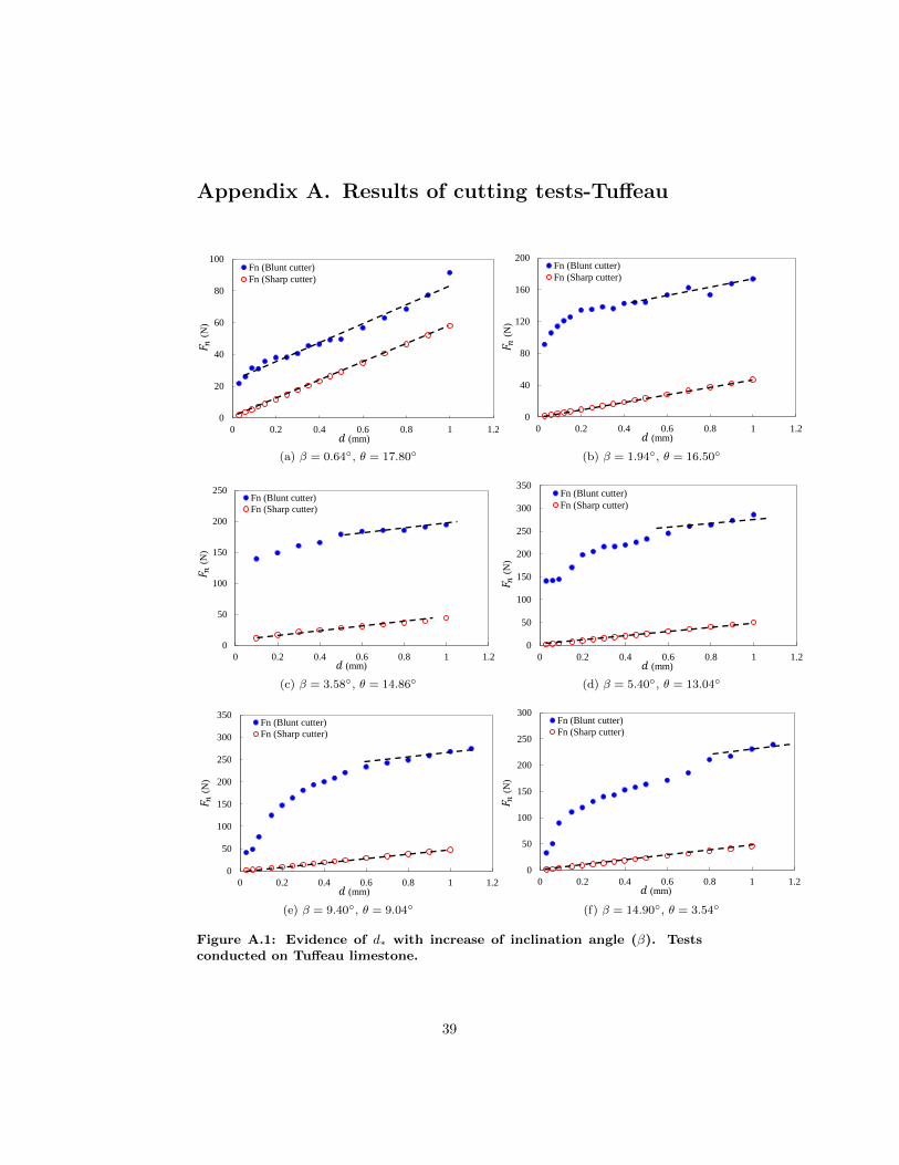
as well illustrated in the results shown in Fig. 14a to Fig. 14f for Mountain Gold
sandstone, the threshold depth of cut d∗ is found significantly larger than the390
projection of the wear flat length in the plane normal to the groove (d∗ > d1),
see Fig. 15. At large inclination angle (where the wear flat acts more as chamfer
or secondary cutting face), the incremental cutting response has not converged
towards the response of a sharp cutter at a depth of cut associated with the onset
of the brittle cutting regime (d > 1.2 mm). As mentioned in the previous section,395
the possible explanation for this observation is the relative backward flow of the
crushed particles which were visually observed during the experimental tests.
The results of Tuffeau limestone compared with Mountain Gold sandstone are
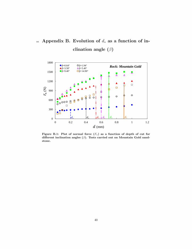
also presented in Appendix A. Also, the evolution of d∗ as a function of the
inclination angle (β) is presented in Appendix B.400
Figure 13: Schematic of two blunt cutters and a sharp cutter with the sameback rake angles and different depths of cut.
27

0
100
200
300
400
500
0 0.2 0.4 0.6 0.8 1 1.2
Fn (Blunt cutter)
Fn (Sharp cutter)
𝐹 𝑛(N
)
𝑑 (mm)
(a) β = 0.64◦, θ = 17.80◦
0
200
400
600
800
0 0.2 0.4 0.6 0.8 1 1.2
Fn (Blunt cutter)
Fn (Sharp cutter)
𝐹 𝑛(N
)
𝑑 (mm)
(b) β = 1.94◦, θ = 16.50◦
0
300
600
900
1200
1500
0 0.2 0.4 0.6 0.8 1 1.2
Fn (Blunt cutter)
Fn (Sharp cutter)
𝐹 𝑛(N
)
𝑑 (mm)
(c) β = 3.58◦, θ = 14.86◦
0
400
800
1200
1600
0 0.2 0.4 0.6 0.8 1 1.2
Fn (Blunt cutter)
Fn (Sharp cutter)
𝐹 𝑛(N
)
𝑑 (mm)
(d) β = 5.40◦, θ = 13.04◦
0
400
800
1200
1600
0 0.2 0.4 0.6 0.8 1 1.2
Fn (Blunt cutter)
Fn (Sharp cutter)
𝐹 𝑛(N
)
𝑑 (mm)
(e) β = 9.40◦, θ = 9.04◦
0
300
600
900
1200
0 0.2 0.4 0.6 0.8 1 1.2
Fn (Blunt cutter)
Fn (Sharp cutter)
𝐹 𝑛(N
)
𝑑 (mm)
(f) β = 14.90◦, θ = 3.54◦
Figure 14: Evidence of d∗ with increase of inclination angle (β). Testsconducted on Mountain Gold sandstone.
28

𝑑∗ 𝑑
𝐹
𝐵𝑙𝑢𝑛𝑡 𝑐𝑢𝑡𝑡𝑒𝑟
𝑆ℎ𝑎𝑟𝑝 𝑐𝑢𝑡𝑡𝑒𝑟
𝑑∗ 𝑑∗
𝐹∗
𝐹∗
𝐹∗ 𝐵𝑙𝑢𝑛𝑡 𝑐𝑢𝑡𝑡𝑒𝑟
𝐵𝑙𝑢𝑛𝑡 𝑐𝑢𝑡𝑡𝑒𝑟
Figure 15: Schematic of the normal behavior of a sharp cutter and a bluntcutter as a function of depth of cut.
7. Conclusions
In the present study, results of cutting tests using a single blunt PDC (Polycrys-
talline Diamond Compact) cutter and a single sharp PDC cutter conducted in
two different rock samples (a coarse grain sandstone and a soft grain limestone)
were presented. An extensive and comprehensive set of cutting tests was carried405
out not only on a wide range of depths of cut but also at different inclination
angles of the wear flat. A unique cutter holder was purposely designed and
manufactured along with a precise experimental protocol implemented so as to
change the angle of inclination (β) in steps of 0.10◦.
The experimental results indicate that the contact force (and therefore the410
contact stress σ) at the wear flat-rock interface is affected by both the depth of
cut (or rate of penetration ROP) and the inclination angle (β). In view of the
three regimes of frictional contact (identified as elastic, elstoplastic and fully
plastic) were introduced in the previous studies [21, 22], the normal contact
stress remains unchanged within the elastic regimes which typically occurs at415
29

small inclination angles. Within the elastoplastic regime of the frictional con-
tact, the findings of this study is consistent with the work of Adachi (1996); the
contact stress increases with depth of cut due to non-conformal contact at the
wear flat-rock interface and then it levels off once the depth of cut (d) reaches
d∗. When the regime of interaction between the wear flat and the substrate is420
within the plastic regime, the contact stress increases steadily with the depth
of cut.
The findings of this research have also shown that the two simultaneous
processes of rock cutting, frictional contact and pure cutting, cannot simply
be considered as fully independent processes. The incremental response of a425
blunt cutter becomes similar to the response of a sharp cutter beyond a depth
of cut (d∗) which is significantly larger than the wear flat projected normal
height (dcr = `sinβ). Also, the results indicate that for a large inclination
angle (β > 7◦, for which the wear flat acts more as a chamfer or second cutting
face [22]) the incremental response of the cutter has not yet converged to the430
response of a sharp cutter beyond a depth of cut greater than 1 mm at, which
the occurrence of the brittle regime occurs.
This research implies that the drilling with a PDC drag bit or cutting model
with a single blunt cutter cannot readily be considered as two independent
“pure cutting” and “frictional contact” processes, Also, value of the inclination435
angle of the wear flat has a significant effect on the cutting response of a drag
bit. This finding plays an important role in analysis of the data obtained from
laboratory experiments and in particular, the numerical simulations of rock
cutting which are generally based on many simplifications. Further work (such
as finite element modeling (FEM) and/or discrete element modeling (DEM)) is440
necessary to compare the experimental results with numerical modeling.
Acknowledgment
The first author would like to thank Joel Sarout and Jeremie Dautriat from
CSIRO (Perth, Australia) for granting access to the Rock Mechanics Testing
30

laboratory, research facilities, and rock samples. The first author is indebted to445
Thomas Richard (from Epslog Engineering SA) for his beneficial discussions and
supervision. The work has been supported by the Deep Exploration Technolo-
gies Cooperative Research Centre whose activities are funded by the Australian
Government’s Cooperative Research Centre Programme. This is DET CRC
Document 2018/1077.450
References
[1] L. Gerbaud, S. Menand, H. Sellami, PDC bits: All comes from the cutter
rock interaction, IADC/SPE Drilling Conference, 21-23 February, Miami,
Florida, USA, Society of Petroleum Engineers, 2006.
[2] F. Bellin, A. Dourfaye, W. King, M. Thigpen, The current state of PDC455
bit technology, World oil 231 (2010).
[3] S. Niu, H. Zheng, Y. Yang, L. Chen, Experimental study on the rock-
breaking mechanism of disc-like hybrid bit, Journal of Petroleum Science
and Engineering (2017).
[4] L. F. Franca, A bit–rock interaction model for rotary–percussive drilling,460
International Journal of Rock Mechanics and Mining Sciences 48 (2011)
827–835.
[5] J. F. Brett, T. M. Warren, S. M. Behr, A. P. Co., Bit whirl: A new theory
of PDC bit failure, SPE Annual Technical Conference and Exhibition,
Society of Petroleum Engineers, 1989.465
[6] Y. Ma, Z. Huang, Q. Li, Y. Zhou, S. Peng, Cutter layout optimization
for reduction of lateral force on PDC bit using kriging and particle swarm
optimization methods, Journal of Petroleum Science and Engineering 163
(2018) 359 – 370.
[7] B. Akbari, Polycrystalline diamond compact bit-rock interaction, M. Sc470
Thesis, Memorial University of Newfoundland, 2011.
31

[8] M. Yahiaoui, J.-Y. Paris, K. Delbe, J. Denape, L. Gerbaud, A. Dourfaye,
Independent analyses of cutting and friction forces applied on a single poly-
crystalline diamond compact cutter, International Journal of Rock Mechan-
ics and Mining Sciences 85 (2016) 20–26.475
[9] T. M. Warren, L. A. Sinor, PDC bits: what’s needed to meet tomorrow’s
challenge, University of Tulsa Centennial Petroleum Engineering Sympo-
sium, 29-31 August, Tulsa, Oklahoma, Society of Petroleum Engineers,
1994.
[10] B. Akbari, S. Miska, The effects of chamfer and back rake angle on PDC480
cutters friction, Journal of Natural Gas Science and Engineering 35 (2016)
347–353.
[11] M. Yahiaoui, J.-Y. Paris, K. Delbe, J. Denape, L. Gerbaud, C. Colin,
O. Ther, A. Dourfaye, Quality and wear behavior of graded polycrystalline
diamond compact cutters, International Journal of Refractory Metals and485
Hard Materials 56 (2016) 87–95.
[12] N. Challamel, H. Sellami, Application of yield design for understanding
rock cutting mechanism, SPE/ISRM Rock Mechanics in Petroleum Engi-
neering, Society of Petroleum Engineers, 1998.
[13] D. A. Glowka, Development of a method for predicting the performance490
and wear of PDC (polycrystalline diamond compact) drill bits, Technical
Report, Sandia National Labs., Albuquerque, NM (USA), 1987.
[14] E. Detournay, P. Defourny, A phenomenological model for the drilling
action of drag bits, International Journal of Rock Mechanics and Mining
Sciences & Geomechanics Abstracts 29 (1992) 13–23.495
[15] A. Wojtanowicz, E. Kuru, Mathematical modeling of PDC bit drilling
process based on a single-cutter mechanics, Journal of Energy Resources
Technology 115 (1993) 247–256.
32

[16] C. Fairhurst, W. Lacabanne, Hard rock drilling techniques, Mine Quarry
Eng 23 (1957) 157–161.500
[17] D. Zijsling, Analysis of temperature distribution and performance of poly-
crystalline diamond compact bits under field drilling conditions, SPE an-
nual technical conference and exhibition, 16-19 September, Houston, Texas,
Society of Petroleum Engineers, 1984.
[18] Y. Zhou, W. Zhang, I. Gamwo, J.-S. Lin, Mechanical specific energy versus505
depth of cut in rock cutting and drilling, International Journal of Rock
Mechanics and Mining Sciences 100 (2017) 287 – 297.
[19] B. Besselink, Analysis and validation of self-excited drill string oscillations,
M. Sc Thesis, Department of Mechanical Engineering, Eindhoven Univer-
sity of Technology, 2008.510
[20] Y. Zhou, E. Detournay, Analysis of the contact forces on a blunt PDC bit,
ARMA 14-7351, 48th US Rock Mechanics / Geomechanics Symposium,
ARMA, 2014.
[21] I. Rostam Sowlat, Effect of cutter and rock properties on the frictional
contact in rock cutting with blunt tools, Ph.D. thesis, Curtin University,515
2017.
[22] I. Rostamsowlat, T. Richard, B. Evans, Experimental investigation on the
effect of wear flat inclination on the cutting response of a blunt tool in rock
cutting, Acta Geotechnica (2018) 1–16.
[23] G. Mensa-Wilmot, Impact resistant PDC drill bit, 2013. US Patent520
8,448,725.
[24] T. Richard, F. Dagrain, E. Poyol, E. Detournay, Rock strength determina-
tion from scratch tests, Engineering Geology 147-148 (2012) 91–100.
[25] M. E. Merchant, Mechanics of the metal cutting process. i. orthogonal
cutting and a type 2 chip, Journal of Applied Physics 16 (1945) 267–275.525
33

[26] M. E. Merchant, Mechanics of the metal cutting process. ii. plasticity
conditions in orthogonal cutting, Journal of Applied Physics 16 (1945)
318–324.
[27] P. Jogi, W. Zoeller, The application of a new drilling model for evalu-
ating formation and downhole drilling conditions, Petroleum Computer530
Conference, Society of Petroleum Engineers, 1992.
[28] I. Evans, The force required to cut coal with blunt wedges, International
Journal of Rock Mechanics and Mining Science and Geomechanics Ab-
stracts 2 (1965) 1–12.
[29] Y. Nishimatsu, The mechanics of rock cutting, International Journal of535
Rock Mechanics and Mining Sciences & Geomechanics Abstracts 9 (1972)
261–270.
[30] M. Lebrun, Etude thique et expmentale de l’abattage Ingerie mnique; Ap-
plication conception des machines d’abattage et de creusement, Ph.D The-
sis, Ecole Nationale Supeure Des Mines de Paris, Fontainebleau, 1978.540
[31] G. P. Cherepanov, M. I. Vorozhtsov, R. M. Eigeles, Rock cutting, Soviet
Physics Doklady 32 (1987) 728–730.
[32] D. A. Glowka, Use of single-cutter data in the analysis of PDC bit designs:
Part 1-development of a PDC cutting force model, Journal of Petroleum
Technology 41 (1989) 797–849.545
[33] T. Warren, A. Sinor, Drag-bit performance modeling, SPE Drilling Engi-
neering 4 (1989) 119–127.
[34] J. B. Cheatham, W. H. Daniels, A study of factors influencing the drillabil-
ity of shales - single-cutter experiments with stratapax drill blanks, ASME
Journal of Energy Resources Technology 101 (1979) 189–195.550
[35] T. Richard, Determination of Rock Strength from Cutting Tests, M. Sc
Thesis, Faculty of the Graduate School of the University of Minnesota,
Minneapolis, Minnesota, USA, 1999.
34

[36] Y. Zhou, J.-S. Lin, Modeling the ductile-brittle failure mode transition in
rock cutting, Engineering Fracture Mechanics 127 (2014) 135 – 147.555
[37] Y. Zhou, J. S. Lin, On the critical failure mode transition depth for rock
cutting, International Journal of Rock Mechanics and Mining Sciences 62
(2013) 131–137.
[38] W. Liu, X. Zhu, J. Jing, The analysis of ductile-brittle failure mode tran-
sition in rock cutting, Journal of Petroleum Science and Engineering 163560
(2018) 311 – 319.
[39] J. Almenara, E. Detournay, Cutting experiments in sandstones with
blunt PDC cutters, Rock Characterization: ISRM Symposium, Eurock’92,
Chester, UK, 14–17 September 1992, Thomas Telford Publishing, 1992, pp.
215–220.565
[40] W. W. Samiselo, Rock-Tool Friction as a Cuttability Predictor, M.Sc The-
sis, Imperial College, London, United Kingdom, 1992.
[41] C. Lasserre, Rock friction apparatus: Realisation de tests de coupe sur
roches a l’Aide d’un outil PDC, Technical Report, Institut en Sciences et
Technologies Geophysique et Geotechniques, Universite de Paris VI, Paris,570
France, 1994.
[42] J. I. Adachi, Frictional contact in rock cutting with blunt tools, M. Sc
Thesis, Civil Engineering, University of Minnesota, 1996.
[43] R. Teale, The concept of specific energy in rock drilling, International
Journal of Rock Mechanics and Mining Sciences & Geomechanics Abstracts575
2 (1965) 57–73.
[44] T. Richard, E. Detournay, A. Drescher, P. Nicodeme, D. Fourmaintraux,
The scratch test as a means to measure strength of sedimentary rocks, SPE
47196, SPE/ISRM Eurock 98, Society of Petroleum Engineers, Trondheim,
Norway, 1998, pp. 1–8.580
35

[45] E. Detournay, A. Drescher, P. Defourny, D. Fourmaintraux, Assessment
of rock strength properties from cutting tests: Preliminary experimental
evidence, volume 1, Proc. of the Colloquium Mundanum on Chalk and
Shales, Brussels, 1995, pp. 13–1.
[46] M. Theodoridou, F. Dagrain, I. Ioannou, Micro-destructive cutting tech-585
niques for the characterization of natural limestone, International Journal
of Rock Mechanics and Mining Sciences 76 (2015) 98 – 103.
[47] I. Rostamsowlat, T. Richard, B. Evans, An experimental study of the effect
of back rake angle in rock cutting, International Journal or Rock Mechanics
and Mining Sciences 107 (2018).590
[48] I. Rostamsowlat, Effect of cutting tool properties and depth of cut in rock
cutting: An experimental study, Rock Mechanics and Rock Engineering
(2018) 1–14.
[49] T. Lhomme, Frictional contact at a rock-tool interface: An experimental
study, M. Sc Thesis, University of Minnesota, 1999.595
[50] F. Dagrain, Etude des mecanismes de coupe des roches avec couteaux Uses
- Approche des mecanismes de frottement sous les couteaux par le concept
du troisieme corps, Ph.D Thesis, Faculte Polytechnique de Mons, 2006.
[51] E. Detournay, T. Richard, M. Shepherd, Drilling response of drag bits:
Theory and experiment, International Journal of Rock Mechanics and600
Mining Sciences 45 (2008) 1347–1360.
[52] L. F. Franca, Drilling action of roller-cone bits: modeling and experimental
validation, Journal of Energy Resources Technology 132 (2010) 043101.
[53] A. Ghasemloonia, D. G. Rideout, S. D. Butt, A review of drillstring vibra-
tion modeling and suppression methods, Journal of Petroleum Science and605
Engineering 131 (2015) 150–164.
36

[54] C. Germay, V. Denoel, E. Detournay, Multiple mode analysis of the self-
excited vibrations of rotary drilling systems, Journal of Sound and Vibra-
tion 325 (2009) 362–381.
[55] B. Besselink, N. van de Wouw, H. Nijmeijer, A semi-analytical study of610
stick-slip oscillations in drilling systems, Journal of Computational and
Nonlinear Dynamics 6 (2011).
[56] H. Qiu, J. Yang, S. Butt, J. Zhong, Investigation on random vibration of
a drillstring, Journal of Sound and Vibration 406 (2017) 74 – 88.
[57] F. Real, A. Batou, T. Ritto, C. Desceliers, R. Aguiar, Hysteretic bit/rock615
interaction model to analyze the torsional dynamics of a drill string, Me-
chanical Systems and Signal Processing 111 (2018) 222–233.
[58] T. Ritto, M. Escalante, R. Sampaio, M. B. Rosales, Drill-string horizontal
dynamics with uncertainty on the frictional force, Journal of Sound and
Vibration 332 (2013) 145–153.620
[59] D. Lobo, T. Ritto, D. Castello, Stochastic analysis of torsional drill-string
vibrations considering the passage from a soft to a harder rock layer, Jour-
nal of the Brazilian Society of Mechanical Sciences and Engineering 39
(2017) 2341–2349.
[60] A. Depouhon, E. Detournay, Instability regimes and self-excited vibrations625
in deep drilling systems, Journal of Sound and Vibration 333 (2014) 2019–
2039.
[61] Y. Khulief, F. Al-Sulaiman, S. Bashmal, Vibration analysis of drillstrings
with self-excited stick–slip oscillations, Journal of sound and vibration 299
(2007) 540–558.630
[62] T. Ritto, R. Aguiar, S. Hbaieb, Validation of a drill string dynamical model
and torsional stability, Meccanica 52 (2017) 2959–2967.
37

[63] A. Ersoy, M. D. Waller, Wear characteristics of PDC pin and hybrid core
bits in rock drilling, Wear 188 (1995) 150–165.
[64] D. H. Zijsling, Rotary drill bit with cutting elements having a thin abrasive635
front layer, 1986. US Patent 4,607,711.
[65] D. A. Glowka, Design considerations for a hard-rock PDC drill bit, Tech-
nical Report, Sandia National Labs., Albuquerque, NM (USA), 1985.
[66] T. Richard, C. Coudyzer, S. Desmette, Influence of groove geometry and
cutter inclination in rock cutting, 44th US Rock Mechanics Symposium and640
5th US-Canada Rock Mechanics Symposium, American Rock Mechanics
Association, 2010.
[67] T. Richard, Personal communications, 2016.
38
Appendix A. Results of cutting tests-Tuffeau
0
20
40
60
80
100
0 0.2 0.4 0.6 0.8 1 1.2
Fn (Blunt cutter)
Fn (Sharp cutter)
𝐹 𝑛(N
)
𝑑 (mm)
(a) β = 0.64◦, θ = 17.80◦
0
40
80
120
160
200
0 0.2 0.4 0.6 0.8 1 1.2
Fn (Blunt cutter)
Fn (Sharp cutter)
𝐹 𝑛(N
)
𝑑 (mm)
(b) β = 1.94◦, θ = 16.50◦
0
50
100
150
200
250
0 0.2 0.4 0.6 0.8 1 1.2
Fn (Blunt cutter)
Fn (Sharp cutter)
𝐹 𝑛(N
)
𝑑 (mm)
(c) β = 3.58◦, θ = 14.86◦
0
50
100
150
200
250
300
350
0 0.2 0.4 0.6 0.8 1 1.2
Fn (Blunt cutter)
Fn (Sharp cutter)𝐹 𝑛
(N)
𝑑 (mm)
(d) β = 5.40◦, θ = 13.04◦
0
50
100
150
200
250
300
350
0 0.2 0.4 0.6 0.8 1 1.2
Fn (Blunt cutter)
Fn (Sharp cutter)
𝐹 𝑛(N
)
𝑑 (mm)
(e) β = 9.40◦, θ = 9.04◦
0
50
100
150
200
250
300
0 0.2 0.4 0.6 0.8 1 1.2
Fn (Blunt cutter)
Fn (Sharp cutter)
𝐹 𝑛(N
)
𝑑 (mm)
(f) β = 14.90◦, θ = 3.54◦
Figure A.1: Evidence of d∗ with increase of inclination angle (β). Testsconducted on Tuffeau limestone.
39
Appendix B. Evolution of d∗ as a function of in-645
clination angle (β)
0
300
600
900
1200
1500
1800
0 0.2 0.4 0.6 0.8 1 1.2
β=0.64° β=1.94°
β=3.58° β=5.40°
β=9.40° β=14.90°
𝐹 𝑛(N
)
𝑑 (mm)
𝑑∗𝑑∗𝑑∗𝑑∗𝑑∗𝑑∗
Rock: Mountain Gold
Figure B.1: Plot of normal force (Fn) as a function of depth of cut fordifferent inclination angles (β). Tests carried out on Mountain Gold sand-stone.
40

0
50
100
150
200
250
300
350
0 0.2 0.4 0.6 0.8 1 1.2
β=0.64° β=1.94°
β=3.58° β=5.40°
β=9.40° β=14.90°
𝐹 𝑛(N
)
𝑑 (mm)
𝑑∗𝑑∗𝑑∗𝑑∗𝑑∗𝑑∗
Rock: Tuffeau
Figure B.2: Plot of normal force (Fn) as a function of depth of cut fordifferent inclination angles (β). Tests carried out on Tuffeau limestone.
41


![ARM-based Flash MCU - produktinfo.conrad.com · 128-Byte RX UART1 PDC Real-time Events PIO High Speed MCI DMA PDC PDC PDC PDC Timer Counter A TC[0..2] UART0 TWCK0 TWD0 TWD1 UTXD0](https://img.pdfslide.us/doc/110x75/5c387e4109d3f23f308b764d/arm-based-flash-mcu-128-byte-rx-uart1-pdc-real-time-events-pio-high-speed.jpg)


![SAM3S8 / SAM3SD8 · 2019. 10. 13. · pioa / piob piodc[7:0] high speed mci datrg pdc pdc pdc pdc pdc pdc pdc pdc pdc pdc pdc pdc pdc dac0 dac1 timer counter 0 tc[0..2] ad[0..14]](https://img.pdfslide.us/doc/110x75/61180b84f50fc135d32d7973/sam3s8-sam3sd8-2019-10-13-pioa-piob-piodc70-high-speed-mci-datrg-pdc.jpg)