Embed Size (px)
Citation preview

Research ArticleAn Optimal Hybrid Control Method for Energy-Saving ofChilled Water System in Central Air Conditioning
Yan Zhang ,1,2,3 Xiaoli Chu,4 and Yongqiang Liu 2
1Faculty Development and Educational Technology Center, Guangdong University of Finance and Economics,Guangzhou 510320, China
2School of Electric Power, South China University of Technology, Guangzhou 510640, China3Foshan Institute of Modern Services, Guangdong University of Finance and Economics, Foshan 528100, China4Center of Network, Guangdong AIB Polytechnic College 510507, China
Correspondence should be addressed to Yan Zhang; [email protected]
Received 18 October 2018; Accepted 26 November 2018; Published 27 December 2018
Academic Editor: Haiping Du
Copyright © 2018 Yan Zhang et al. This is an open access article distributed under the Creative Commons Attribution License,which permits unrestricted use, distribution, and reproduction in any medium, provided the original work is properly cited.
Chilled water system of central air conditioning is a typical hybrid system; variable frequency behavior with amplitude limited ofpumps reflects continuous and discrete dynamic characteristics. The way of energy-saving is variable water volume, via variablefrequency behavior of pumps to gain adjustment of power consumption. Facing the situation of the variable frequency pumpswith parallel operation, single continuous or discrete modeling cannot reflect the hybrid features. Thus, the control method willhave some questions, such as bad energy-saving effect, difficult accurate adjustment of cold capacity, and low running energyefficiency. However, hybrid system modeling can reflect hybrid dynamic behavior of pumps, which is combining continuous anddiscrete features. The questions of nonlinear and multiparameters can be solved by control method based on hybrid system. Here,an optimum control method is proposed with the principle of the minimum, by setting the minimum power consumption as theperformance function in fixed time, which realizes variable control of pumps and accurate adjustment of temperature inside room.At last, it shows the system characteristics and energy-saving affection by hybrid systemmodeling and the optimumcontrolmethod.
1. Introduction
Nowadays China is a country with severe energy shortages.Energy conservation and emission reduction, as an importantbasic national policy of China, have far-reaching guidingsignificance for the development of industrial technology. Atthe national level, the “13th Five-Year Plan for Comprehen-sive Energy Conservation and Emission Reduction” clearlystates that vigorously developing energy-saving products andtechnologies promoting the transformation of high-energy-consuming enterprises or industries and fully implementingenergy-saving and emission reduction are the key tasks in thetechnical field. In building energy consumption, central air-conditioning accounts for 50-70% of total energy consump-tion [1], followed by lighting and other types of electricalequipment. Energy-saving of air-conditioning systems arenot only the key to the success of building energy-savingwork, but also the realization of a conservation-orientedsociety [2].
In addition to the chiller, the energy-saving control ofthe central air-conditioning is mainly for pumps and fans.The chilled water system is the research object, which ismainly reflected in the variable flow control. At present, thevariable flow control objects of the central air conditioningwater system mainly include return water temperature [3],supply and return water temperature difference [4, 5], andsupply and return water pressure difference [6], as wellas temperature difference and differential pressure cascadecontrol [7]. The control methods mainly include switchcontrol, PID control, fuzzy control, adaptive control, opti-mization control, and decoupling control. J. Mohammed etal. [8] proposed a dual-proportional PID hybrid controllerto improve cooling performance and achieve energy savingof chilled water flow. J. Li et al. [9] adopted neural networkadaptive control method to monitor the system’s work. Thestate adjusts the parameters of the neural network controllerin real time, realizes the intelligent control, and verifies thedynamic performance and steady state performance of the
HindawiJournal of Control Science and EngineeringVolume 2018, Article ID 3750859, 9 pageshttps://doi.org/10.1155/2018/3750859

2 Journal of Control Science and Engineering
method through simulation. G. Liu et al. [10] combines thetechnical advantages of fuzzy control and PID algorithm topropose a parameter adaptive fuzzy PID. The algorithm hasachieved good test results; M. Koor [11] proposed a predictivecontrolmethod for finding the best energy efficiency point forthe variable frequency pump set with the same performanceparameters, considering the pressure and flow factors. Luoet al. [12] designed a system based on PLC fuzzy predictioncombined with expert practical experience and control rules,which embodies better control effects, T.Zhao et al. [6]. Thenumber of parallel hydraulic pumps for chilled water systems.Compared with the rate, an online optimization controlstrategy is proposed, and the performance improvement isdemonstrated through experiments. Zhang Yan et al. [13]proposed a kind of central air-conditioning cooling basedon hybrid system model. The model of energy saving inthe frozen water system, and set the action of the pumpgroup for frequency conversion and switching, and demon-strate the applicability of the model and control strategythrough computer simulation; H.Wang et al. [14] put variousenergy saving such as variable flow, temperature differenceand differential pressure. The technology is compared withthe corresponding control strategy to analyze the energysaving effect of different methods. J.M. Gordon et al. useda simple thermodynamic model that captures the universalaspects of chiller behavior [15]. Next, they used the simplethermodynamic model to predict the fundamental relationbetween coefficient of performance and cooling rate for thecentrifugal chiller [16].
The traditional model and control method is based on asimple continuous or discrete dynamic model, which cannotaccurately reflect the mixed dynamic behavior of continuousfeatures and discrete features. Hybrid systems contain bothcontinuous and discrete characteristics, and have significantadvantages in dealing with power system and appliancemodeling issues. The central air-conditioning chilled watersystem is a typical hybrid system. Its energy-saving controlis mainly used to change the flow of the water system. Itis realized by the frequency conversion or switching actionof the pumps group, which reflects the hybridization withthe goal of minimum energy consumption. According to thechange of the cooling demand, real-time adjustment of theflow of the chilled water system can effectively realize thepower saving of the pumps group. Therefore, the modelingand energy-saving control strategies of chilled water systemsbased onhybrid systems are highly targeted.Thenonlinearity,large time lag, and multiparameters of chilled water systemscan be modeled and effectively solved by hybrid systems.Thus, it has extremely important theoretical significance.
2. Mathematical Description of PiecewiseAffine System
Throughout, the following notation is adopted: R and C
denote the fields of real and complex number, respectively;R𝑛,R𝑚,R𝑙, andR𝑠 denote the n,m, l, and s-dimensional realEuclidean spaces; R𝑛×𝑛 denotes the space of 𝑛 × 𝑛 matriceswith real entries; 𝑥𝑖 denotes the 𝑖𝑡ℎ component of the vector 𝑥
in R𝑛, respectively; 𝑎𝑖𝑗 denotes the entry in the (i, j) positionof the matrices 𝐴 or 𝐸 in R𝑛×𝑛.
The Piecewise Affine System (PWA) [17] is a class inhybrid systems. The continuous-time PWA model can bedescribed as follows:
�� (𝜏) = 𝐴 𝑖𝑥 (𝜏) + 𝐵𝑖𝑢 (𝜏) + 𝑓𝑖𝑦 (𝜏) = 𝐶𝑖𝑥 (𝜏) + 𝐷𝑖𝑢 (𝜏) + 𝑔𝑖 (1)
which satisfies [ 𝑥(𝜏)𝑢(𝜏) ] ∈ Ω𝑖, where 𝑥(𝜏) ∈ R𝑛 and 𝑢(𝜏) ∈R𝑚, 𝑦(𝜏) ∈ R𝑙, respectively, represent the system’s statevariables, input variables, and output variables. 𝜏 represents atime scalar. 𝑓𝑖 and 𝑔𝑖 are constant vectors.𝐴 𝑖 and𝐶𝑖 representthe state matrices of the system; 𝐵𝑖 and 𝐷𝑖 are the inputmatrices of the system. Ω𝑖 denotes a convex polyhedron thatrepresents the state variable of the system and the inputvariable space, which is a convex partition, namely, 𝑋 × 𝑈 =∪Ω𝑖, Ω𝑖 ∩Ω𝑗 = ⌀, 𝑖 = 𝑗. The system switches when the stateof the system crosses the boundary. The system consists of𝑁subsystems, ∪𝑁𝑖=1Ω𝑖 = Ω, and the system switches betweensubsystems. The switching rules can be state dependent, timedependent, and so on.
3. Mathematical Model of Room TemperatureChanges in Air Conditioning Systems
The mathematical model of air-conditioned rooms adoptsa common method: based on the dynamic change of theheat capacity in the air-conditioned room, the cold sendingair is the control input, and the temperature in the air-conditioned room is the state variable. The heat dissipationdevice and human constitute a disturbance of heat and theheat transfer medium such as wall surface, ceiling, window,etc. can also affect the indoor temperature to a certain extent,and can be considered as a disturbance or a fixed value. Thenthis dynamic process conforms to the law of conservationof energy and, according to the adjustment of appropriateparameters, the temperature in the air-conditioned roomcan be stabilized at the set value, as shown in Figure 1. Thedynamic heat balance equation can be expressed as
𝐶z𝑑𝑡𝑑𝜏 = 𝑞sa𝑐a (𝑡sa − 𝑡) + ∑𝐾𝑖𝐴 𝑖 (𝑡𝑖 − 𝑡) + 𝑄 (2)
where𝐶𝑧 is the heat capacity in the air-conditioned room,J/K; t is the real-time temperature of the air-conditionedroom, ∘C; 𝜏 is the time, s; 𝑞𝑠𝑎 is the air supply volume to theair-conditioned room, kg/s; 𝑐𝑎 is the specific heat capacity ofthe air, J/(kg⋅K); 𝑡𝑠𝑎 is the air supply temperature of the airconditioning, ∘C;𝐾𝑖 is the heat transfer coefficient of the heattransfer medium (wall, window, and roof), W/(m2⋅K); 𝐴 𝑖 isthe heat transfer mediumThe area of the wall (wall, window,and roof), m2; 𝑡𝑖 is the temperature of the inner surface ofthe envelope structure (wall, window and roof), ∘C; Q is theheat dissipation of the human body and equipment in the air-conditioned room, W.
The cooling capacity produced by the cold units is trans-ferred from the chilled water system to the air system, and the

Journal of Control Science and Engineering 3
sending air
return airAHU
fresh air(if necessary)
inside temperature
potential heat
Equipment and human
heat transferred from wall, window and roof
Figure 1: Schematic diagram of dynamic thermal equilibrium in air conditioning room.
heat exchange is realized by the cooler in the Air HandlingUnit (AHU), and the heat exchange efficiency is set to 𝜂. TheAHU is also responsible for mixing the indoor return air withthe outdoor fresh air, and sending the filtered clean air intothe air-conditioned room through the cooler. Among them,the ratio of the fresh air volume 𝑞𝑛 to the return air volume 𝑞𝑟is 1-w:w. According to the requirements of Chinese “PublicBuilding Energy Efficiency Design Standards,” there shouldgenerally be a fresh air ratio of not less than 15% to ensureindoor air quality.Then the expression of the cooling betweenthe water system and the air system is
𝛾𝜂𝑄w = 𝑄a = (𝑄xr + 𝑄qr) (3)
By introducing the expressions of the water systemcarrying the cold capacity and the cooling capacity carriedby the air system, the formula (3) can be rewritten as
𝛾𝜂𝑞w𝑐wΔ𝑡 = (1 − 𝑤) 𝑞sa𝑐a (𝑡out − 𝑡sa) + 𝑤𝑞sa𝑐a (𝑡 − 𝑡sa)+ 𝑄qr
(4)
where 𝛾 is the percentage of cold capacity assigned to anair-conditioned room, 0 ≤ 𝛾 ≤ 100%; 𝑄w is the cold capacitycarried by the water system, W; 𝑄a is the cold capacity thatis sent to the air-conditioned room by the AHU, W; 𝑄xr isthe sensible heat in the air-conditioned room, W; 𝑄qr is thepotential heat in the room, W; 𝑞𝑤 is the flow rate of thewater system, kg/s; 𝑐𝑤 is the specific heat capacity of water,J/(kg⋅K); Δt is a constant temperature difference between thesupply and return water, ∘C; tout is the fresh air temperatureintroduced from the outside, ∘C.
Bringing (4) into the heat balance equation (2) of theroom, we can get
𝐶z𝑑𝑡𝑑𝜏 = −𝛾𝜂𝑞w𝑐wΔ𝑡 − [(1 − 𝑤) 𝑞sa𝑐a + ∑𝐾𝑖𝐴 𝑖] 𝑡
+ (1 − 𝑤) 𝑞sa𝑐a𝑡out + ∑𝐾𝑖𝐴 𝑖𝑇𝑖 + 𝑄 + 𝑄qr
(5)
Set the state variable 𝑥(𝜏) = 𝑡(𝜏) and the input variable𝑢(𝜏) = 𝑞w(𝜏), use the variable water volume of water system
and the constant air volume of air system transfer modes [3,13], and use the differential equation to describe the systemmodel:
𝑥 (𝜏) = 𝐴𝑥 (𝜏) + 𝐵𝑢 (𝜏) + 𝐻𝑦 (𝜏) = 𝑥 (𝜏) (6)
The system parameters are
𝐴 = −(1 − 𝑤) 𝑞sa𝑐𝑎 + ∑𝐾𝑖𝐴 𝑖𝐶𝑧𝐵 = −𝛾𝜂𝑐wΔ𝑡𝐶𝑧𝐻 = (1 − 𝑤) 𝑞sa𝑐a𝑇out + ∑𝐾𝑖𝐴 𝑖𝑇𝑖 + 𝑄 + 𝑄qr𝐶𝑧
(7)
where the behaviors of the pumps group show the hybridcharacteristics. First, the water system of the air conditioningis dynamic and random, and the factors affecting the sys-tem characteristics also show multivariate, dynamic, strongcoupling, and nonlinear relationship. Characteristics [18];second, in variable flow control method, the water flow isgenerally not less than 50% of the rated value, otherwisethe Coefficient of Performance (COP) of the pump will beabruptly attenuated, so the range of variable flow is limited to[50% rated, 100% rated], showing continuous characteristicswithin this range. If the cold capacity is reduced, the flowcontrol is out of the frequency conversion range, and theamplitude truncation occurs, showing a discrete characteris-tic.The flow constraints of a single pump and the entire water

4 Journal of Control Science and Engineering
ChillerUnit
AHU
AHU
pump
pump
Figure 2: Schematic diagram of cold capacity transfer process in chilled water system.
system can be expressed by mathematical descriptions as
𝑢𝑖 ={{{{{{{{{
0.5𝑢𝑖0, 𝑢 < 0.5𝑢𝑖0𝑢𝑖0, 𝑢 > 𝑢𝑖0𝑢𝑖, 0.5𝑢𝑖0 ≤ 𝑢 ≤ 𝑢𝑖0
, 𝑖 = 1, 2, . . . , 𝑁p (8a)
𝑢s =𝑁p∑𝑖=1
𝑢𝑖 (8b)
𝑢 ={{{{{{{{{
0.5𝑢s0, 𝑢 < 0.5𝑢s0
𝑢s0, 𝑢 > 𝑢s0
𝑢, 0.5𝑢s0 ≤ 𝑢 ≤ 𝑢s0
(9)
where 𝑢𝑖 is the flow rate of the i-th pump as the i-th inputvariable; ui0 is the rated flow of the i-th pump, which is theconstant; 𝑁𝑝 is the number of variable-frequency pumps; 𝑢𝑠is the flow of the whole water system; us0 is the rated flow rateof the whole water system.The schematic diagram of the coldcapacity of the water system is shown in Figure 2.
4. Hybrid Optimization Control StrategyBased on the Minimum Principle
According to the minimum principle proposed by the formerSoviet scholar Pontiac King, the water consumption of thewater system in the finite time is set to the performancefunctional J, and the optimal allowable control 𝑢 is soughtto minimize the performance function. u is a multivariateparameter, which is limited to a closed set and satisfies theinequality constraint 𝑔[𝑥(𝜏), 𝑢(𝜏), 𝜏] ≥ 0, and 𝑔 is a r-dimensional continuous vector variable function, 𝑟 ≤ 𝑚.
Because there are many ways to control the frequencyof the pumps group, the energy saving effect is also quitedifferent.Themethod adopts a fixed terminal pressure differ-ence control mode, which sets an electric regulating valve anda differential pressure transmitter on the most unfavorableloop, so that the power of the pump is between one powerand three powers [19]. In order to facilitate the calculation, it
is approximated that the power (P, W) of the pump and therotational speed (n, rad/s) are squared, and the flow rate ofthe pump is proportional to the rotational speed, i.e., 𝑛𝑖/𝑛𝑖0 =𝑞w𝑖/𝑞w𝑖0, where 𝑛𝑖 is the rotational speed of a pump, rad/s,ni0 is the rated speed of the pump, rad/s; 𝑞𝑤𝑖 is the flow ofa pump, kg/s; qwi0 is the rated flow of the pump, kg/s. Let𝑃0/𝑞20 = 𝜉. Then the performance function is the sum of theenergy consumption of the variable frequency pumps, whichcan be expressed as
𝐽 = ∫𝜏𝑓𝜏𝑜
𝐿 [𝑥 (𝜏) , 𝑢 (𝜏) , 𝜏] 𝑑𝜏 = ∫𝜏𝑓𝜏𝑜
(𝑁p∑𝑖=1
𝜉𝑖𝑢𝑖2)𝑑𝜏 (10)
where 𝐿 is a continuous differentiable quantity function;𝜏0 and 𝜏𝑓 are initial and terminal moments, respectively, s.Select the Hamilton function as
𝐻 = 𝐿 [𝑥 (𝜏) , 𝑢 (𝜏) , 𝜏] + 𝜆𝑇𝑓 [𝑥, 𝑢, 𝜏]= 𝑁p∑𝑖=1
𝜉𝑖𝑢𝑖2 + 𝜆𝑇(𝐴𝑥 + 𝑁p∑𝑖=1
𝐵𝑢𝑖 + 𝐻) (11)
where 𝜆 is the costate vector and 𝑓[⋅] is the state functionof the system formula (6), 𝑓[⋅] = ��.
First, suppose the extremum condition and the costateequation are analyzed under the condition of unconstrainedcontrol; then the optimal control is discussed according to theactual constraints.
Let
𝜕𝐻𝜕𝑢 = 2𝑁p∑𝑖=1
𝜉𝑖𝑢𝑖 +𝑁p∑𝑖=1
𝐵𝜆 = 0 (12)
We get
𝑢∗𝑖 (𝜏) = −𝐵𝜆 (𝜏)2𝜉𝑖 (13)
which is
𝑢∗ (𝜏) = 𝑁p∑𝑖=1
𝑢𝑖 (𝜏) (14)

Journal of Control Science and Engineering 5
Then the equation of state can be rewritten as
�� = 𝐴𝑥 − 𝐵2𝜆2𝑁p∑𝑖=1
1𝜉 𝑖 + 𝐻 (15)
The coordination equation is
�� = −𝜕𝐻𝜕𝑥 = −𝐴𝜆 (16)
Find the second derivative of the state equation:
𝑥 = 𝐴�� − ��𝐵22𝑁p∑𝑖=1
1𝜉 𝑖 + ��
= 𝐴(𝐴𝑥 − 𝐵2𝜆2𝑁p∑𝑖=1
1𝜉 𝑖 + 𝐻) + 𝐴𝐵2𝜆2𝑁p∑𝑖=1
1𝜉 𝑖(17)
We get
�� = 𝐴2𝑥 + 𝐴𝐻 (18)
Integral can be obtained
𝑥 (𝜏) = 𝐶1𝑒−𝐴𝜏 + 𝐶2𝑒𝐴𝜏 − 𝐻𝐴 (19)
where 𝐶1 and 𝐶2 are undetermined coefficients and (19) issubstituted into the equation of state (15) and the coordina-tion equation can be obtained as
𝜆 (𝜏) = 4𝐴𝐵2∑𝑁p𝑖=1 (1/𝜉𝑖)𝐶1𝑒
−𝐴𝜏(20)
Furthermore, substituting (20) into (14) for optimalcontrol,
𝑢∗𝑖 (𝜏) = − 2𝐴𝜉𝑖𝐵∑𝑁p𝑖=1 (1/𝜉𝑖)𝐶1𝑒
−𝐴𝜏(21)
Substituting the initial condition 𝑥(𝜏0) = 𝑥0 and theterminal constraint 𝑁[𝑥(𝜏𝑓), 𝜏𝑓] = 0 (or terminal condition𝑥(𝜏𝑓) = 𝑥𝑓), the optimal state trajectory 𝑥∗ and the optimalperformance function 𝐽∗ are obtained together, where𝑁 is as-dimensional continuous differentiable vector function, 𝑠 ≤𝑛; 𝜏0 and 𝜏𝑓 are the initial and terminalmoments, respectively,s; 𝑥0 and 𝑥𝑓 are the initial and terminal values of the statevariable, respectively.
The goal proposed in this paper is that the energyconsumption is minimum, and the boundary conditions aredegenerated into fixed initial and terminal constant values,that is, 𝑥(𝜏0) = 𝑥0 and 𝑥(𝜏𝑓) = 𝑥𝑓, respectively. In orderto obtain the optimal state trajectory 𝑥∗ and the optimalperformance function 𝐽∗, substitute the initial condition𝑥(𝜏0) = 𝑥0 and the terminal condition 𝑥(𝜏𝑓) = 𝑥𝑓 into (19)and determine the values of the undetermined coefficients 𝐶1and𝐶2 in the equation of state (19), the coordination equation(20), and the control equation (21).
Considering the limitation of (9) for water system flow,when 𝑢𝑠 is used as a single input variable, the optimal controlbased on the minimum principle is essentially the formof limiting amplifier. However, considering the multi-inputvariable of multipump and the hybrid dynamic behaviorof frequency conversion and truncation, the flow rate ofwater system is only the sum of the flow rate of multipump,as shown in equation (8a) and (8b), as another constraintcondition for input variable.Therefore, in order to achieve thenecessary conditions for optimal control, the optimal control𝑢∗ must be required to take values from the allowed finiteclosed set (8a), which is
𝑢∗𝑖 ={{{{{{{{{
0.5𝑢𝑖0, 𝑢∗𝑖 < 0.5𝑢𝑖0𝑢𝑖0, 𝑢∗𝑖 > 𝑢𝑖0𝑢𝑖, 0.5𝑢𝑖0 ≤ 𝑢∗𝑖 ≤ 𝑢𝑖0
(22)
5. Case Analysis
Assume that the building area of air-conditioned room is 120m2 and the height is 3m. The central air-conditioning sendscold air to the indoor temperature and the indoor tempera-ture is required to be within a limited time (3 minutes), andthe initial temperature (𝑡0, 30∘C) is reduced to the settingtemperature (tset, 26
∘C), and the goal of power consumptionin accordance with the control strategy is minimal. Thechilled water system has four variable frequency water pumpswith different parameters, and they never leave the work.They transport the cold capacity produced by the cold unit tothe AHU for heat exchange and send it into the room in theform of cold air. Assume that the thermodynamic parametersin the air-conditioned room and the parameters and values ofthe water system pump are shown in Table 1.
Then, (6) can be numerically
𝑥 (𝜏) = −0.0002098𝑥 (𝜏) − 0.003374𝑢 (𝜏) + 0.005651𝑦 (𝜏) = 𝑥 (𝜏) (23)
The performance functional (10) can be rewritten as
𝐽 = ∫1800
(609.6𝑢12 + 1567𝑢22 + 3858𝑢32+ 4542𝑢42) 𝑑𝜏
(24)
The Hamilton function (11) is updated to
𝐻 = 𝐿 [𝑥 (𝜏) , 𝑢 (𝜏) , 𝜏] + 𝜆𝑇𝑓 [𝑥, 𝑢, 𝜏] = 609.6𝑢12+ 1567𝑢22 + 3858𝑢32 + 4542𝑢42+ 𝜆𝑇 {−0.0002098𝑥 (𝜏)− 0.003374 [𝑢1 (𝜏) + 𝑢2 (𝜏) + 𝑢3 (𝜏) + 𝑢4 (𝜏)]+ 0.005651}
(25)
After the solution of the equation of state (formula(19)) is digitized, substitute the initial value (30∘C, 0s) and
6 Journal of Control Science and Engineering
Table 1: Symbols and values of parameters in cold capacity transferprocess.
Parameter (Description) Valueindoor hear capacity, 𝐶z (KJ/K) 469specific heat of air, 𝑐a (kJ/kg∗k) 1.01specific heat of water, 𝑐w (kJ/kg∗k) 4.186temperature of fresh air, 𝑡out (∘C) 26setting temperature, 𝑡set (∘C) 25indoor initial temperature, 𝑡0 (∘C) 30volume of sending air, 𝑞sa (kg/s) 0.623temperature of walls, windows, and roof,respectively, 𝑡i (∘C) 35,36,35
area of walls, windows, and roof,respectively, Ai, (m
2) 80,5,0
heat transfer coefficient of walls,windows, and roof, respectively, Ki,(W/m2∗k) 0.047,0.054,0.051
latent heat load, 𝑄qr (W) 25random heat load, 𝑄 (W) 30return air rate,𝑤 0.85transfer efficiency from water system toair system, 𝜂 0.9
ratio of cooling capacity allocation, 𝛾 7%temperature difference,△𝑡 (∘C) 6rated power, respectively, P0 (kW) 1.69;2.17;4.91;10.6rated flow, respectively, 𝑞w0 (L/s) 0.61;0.75;1.77;4.17
Table 2: Square ratio of rated power and rated flow.
Number Rated volumeL/s
Rated powerkW 𝜉
1 4.17 10.6 609.62 1.77 4.91 15673 0.75 2.17 38584 0.61 1.69 4542
the terminal value (26∘C, 180s) and find the undeterminedcoefficients 𝐶1 and 𝐶2 as -51.751 and 54.811. Then the solutionto the equation of state can be updated to
𝑥 (𝜏) = −51.751𝑒0.0002098𝜏 + 54.811𝑒−0.0002098𝜏 + 26.94 (26)
From the costate equation (20), the square ratio of ratedpower to rated flow (Table 2), the numerical solution of thecostate equation is obtained
𝜆 (𝜏) = 1.383300𝑒0.0002098𝜏 (27)
Then the optimal governing equation can be obtained as
𝑢∗𝑖 (𝜏) ={{{{{{{{{{{{{{{
3.828𝑒0.0002098𝜏, 𝑖 = 11.489𝑒0.0002098𝜏, 𝑖 = 20.605𝑒0.0002098𝜏, 𝑖 = 30.514𝑒0.0002098𝜏, 𝑖 = 4
(28a)
26
26.5
27
27.5
28
28.5
29
29.5
30
20 40 60 80 100 120 140 160 1800time (s)
R∗ (∘C)
Figure 3: Optimal state curve.
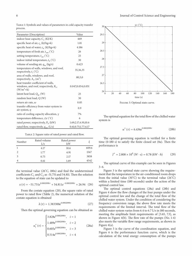
Theoptimal equation for the total flowof the chilledwatersystem is
𝑢∗ (𝜏) = 6.436𝑒0.0002098𝜏 (28b)
The optimal governing equation is verified for a finitetime (0-180 s) to satisfy the finite closed set (8a). Then theperformance is
𝐽∗ = 2.808 × 10⁶ (𝑊 ⋅ s) = 0.78 (𝑘𝑊 ⋅ ℎ) (29)
The optimal curve of this example can be seen in Figures3–6.
Figure 3 is the optimal state curve showing the require-ment that the temperature in the air-conditioned room dropsfrom the initial value (30∘C) to the terminal value (26∘C)within a limited time (180 seconds) under the action of theoptimal control law.
The optimal control equations (28a) and (28b) andFigure 4 show the flow changes of the four pumps under theoptimal control law and the change of the total flow of thechilled water system. Under the condition of considering thefrequency conversion range, the above flow rate meets therequirements of the limited interval. The total flow of thechilled water system varies from 6.4 to 6.7 L/s in 180 seconds,meeting the amplitude limit requirements of [3.65, 7.3], asshown in Figure 4(b). The flow rate of the pumps (No. 1-4)also meets the variable flow range requirements, as shown inFigure 4(a).
Figure 5 is the curve of the coordination equation, andFigure 6 is the performance function curve, which is thecalculation of the total energy consumption of the pumps

Journal of Control Science and Engineering 7
0
0.5
1
1.5
2
2.5
3
3.5
4
4.5 ui∗ (L/s)
12
34
20 40 60 80 100 120 140 160 1800time (s)
(a) Optimal control curve (𝑢i)
0 20 40 60 80 100 120 140 160 180time (s)
6.4
6.45
6.5
6.55
6.6
6.65
6.7 u∗ (L/s)
(b) Optimal control curve (u)
Figure 4
0 20 40 60 80 100 120 140 160 180time (s)
1.38
1.39
1.4
1.41
1.42
1.43
1.44 ×10⁶ ∗
Figure 5: Optimal costate curve.
group. Compare the fixed frequency operation of the pumpsgroup, the energy saving situation can be calculated as
𝜀 = 1 − 𝐽∗∫1800
(∑4𝑖=1 𝑃0𝑖) 𝑑𝜏 = 1 − 2.808 × 1063.4866 × 106= 19.46%
(30)
0
0.5
1
1.5
2
2.5
3 ×10 6 J∗ (W∗s)
20 40 60 80 100 120 140 160 1800time (s)
Figure 6: Optimal performance curve.
According to the calculation of (30), the optimal controlstrategy based on theminimumprinciple of the energy savingrate of 19.46% for the pumps group of the chilled water systemwithin 3 minutes when the indoor temperature drops to theset temperature.
8 Journal of Control Science and Engineering
0 20 40 60 80 100 120 140 160 180time (s)
25.5
26
26.5
27
27.5
28
28.5
29
29.5
30x (∘C)
Figure 7: Temperature variation (compare with group controlstrategy).
0 20 40 60 80 100 120 140 160 180time (s)
4
4.5
5
5.5
6
6.5
7
7.5u (L/s)
Figure 8: Volume variation (compare with group control strategy).
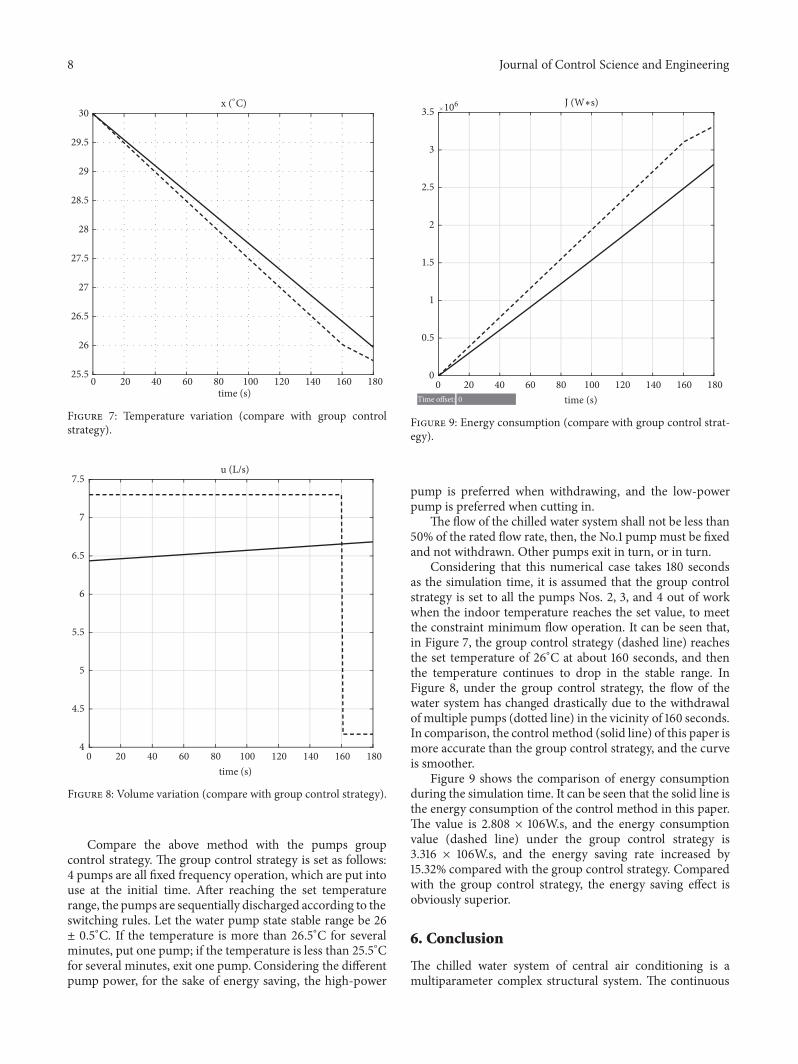
Compare the above method with the pumps groupcontrol strategy. The group control strategy is set as follows:4 pumps are all fixed frequency operation, which are put intouse at the initial time. After reaching the set temperaturerange, the pumps are sequentially discharged according to theswitching rules. Let the water pump state stable range be 26± 0.5∘C. If the temperature is more than 26.5∘C for severalminutes, put one pump; if the temperature is less than 25.5∘Cfor several minutes, exit one pump. Considering the differentpump power, for the sake of energy saving, the high-power
0 20 40 60 80 100 120 140 160 180time (s)
0
0.5
1
1.5
2
2.5
3
3.5 106 J (W∗s)
Time offset: 0
Figure 9: Energy consumption (compare with group control strat-egy).
pump is preferred when withdrawing, and the low-powerpump is preferred when cutting in.
The flow of the chilled water system shall not be less than50% of the rated flow rate, then, the No.1 pumpmust be fixedand not withdrawn. Other pumps exit in turn, or in turn.
Considering that this numerical case takes 180 secondsas the simulation time, it is assumed that the group controlstrategy is set to all the pumps Nos. 2, 3, and 4 out of workwhen the indoor temperature reaches the set value, to meetthe constraint minimum flow operation. It can be seen that,in Figure 7, the group control strategy (dashed line) reachesthe set temperature of 26∘C at about 160 seconds, and thenthe temperature continues to drop in the stable range. InFigure 8, under the group control strategy, the flow of thewater system has changed drastically due to the withdrawalof multiple pumps (dotted line) in the vicinity of 160 seconds.In comparison, the control method (solid line) of this paper ismore accurate than the group control strategy, and the curveis smoother.
Figure 9 shows the comparison of energy consumptionduring the simulation time. It can be seen that the solid line isthe energy consumption of the control method in this paper.The value is 2.808 × 10⁶W.s, and the energy consumptionvalue (dashed line) under the group control strategy is3.316 × 106W.s, and the energy saving rate increased by15.32% compared with the group control strategy. Comparedwith the group control strategy, the energy saving effect isobviously superior.
6. Conclusion
The chilled water system of central air conditioning is amultiparameter complex structural system. The continuous

Journal of Control Science and Engineering 9
and discrete dynamic behaviors of the pumps group deter-mine the mixed characteristics of mathematical modeling.Theminimum energy consumption is the goal for the energy-saving control strategy based on hybrid system. The methodbased on the minimum principle, the optimal control lawis established, the frequency conversion regulation of thepumps group is realized, and the optimal state trajectoryand optimal association are obtained. The trajectory ofthe state and the applicability of the method are furtherverified by numerical examples and computer simulation.The method shows a more accurate indoor temperatureregulation effect, a clearer pump group flow control process,and an objective function calculation result. Due to thevariety of energy-saving control methods for chilled watersystems, the adjustment effects are not the same, and thereare also large differences in energy-saving effects. The controlstrategy of this paper adopts idealized approximation resultsin water pipe network resistance and pump energy efficiency.Therefore, there are certain limitations. In actual engineeringcases, it is still necessary to correct and improve through alarge number of measured data.
Data Availability
The data used to support the findings of this study areincluded within the article.
Conflicts of Interest
The authors declare that they have no conflicts of interest.
Acknowledgments
The research was supported by the National Natural ScienceFoundation of China (No. 61104181).The simulationworkwassupported byDr.MoLili (ORCID ID: 0000-0002-8604-5562)from South China University of Technology.
References
[1] L.-J. Zhang, Fuzzy Neural Network Control Principle andEngineering Application, Harbin Institute of Technology Press,Harbin, 2004.
[2] Y. Z. Kang and B. Hua, “Technical and Economic Analysis ofDistrict Cooling System,” Gas & Heat, vol. 27, no. 11, pp. 79–82,2007.
[3] Y. Zhang, Y. Liu, and Y. Liu, “Stability analysis for a type ofmultiswitching system with parallel structure,” MathematicalProblems in Engineering, vol. 2018, Article ID 3834601, 16 pages,2018.
[4] G.-Q. Zhang, Y.-Z. Xu, J. Han, T. Liu, and H.-P. Wu, “Researchon optimal economic temperature difference between thechilled water supply and return model of a district-coolingsystem,” Hunan Daxue Xuebao/Journal of Hunan UniversityNatural Sciences, vol. 42, no. 9, pp. 128–133, 2015.
[5] Y. Zhang, X. L. Chu, and Y. Q. Liu, “Cold Transmitting Controland Terminal Cold Adjusting of District Cooling System,”Journal of South China University of Technology, vol. 45, no. 10,pp. 26–33, 2017.
[6] Z. Tianyi, Z. Jili, and M. Liangdong, “On-line optimizationcontrol method based on extreme value analysis for parallelvariable-frequency hydraulic pumps in central air-conditioningsystems,” Building and Environment, vol. 47, no. 1, pp. 330–338,2012.
[7] X.-K. Xiao, X.-Q. Jin, P.-J. Liu, and Z.-M. Du, “Research onOptimal Control of Chilled Water Temperature and Head ofSecondary Pump in VWV Systems,” Fluid Machinery, vol. 23,no. 5, pp. 42–45, 2004.
[8] J. A.-K. Mohammed, F. M. Mohammed, and M. A.-S. Jab-bar, “Investigation of high performance split air conditioningsystem by using Hybrid PID controller,” Applied �ermalEngineering, vol. 129, pp. 1240–1251, 2018.
[9] J.-J. Li, Q.-F. Sheng, and B. Ma, “Temperature and HumidityAdaptive Control in Centre Air-conditioning System Based,”Instrument Technique & Sensor, vol. 28, no. 1, pp. 55–57, 2007.
[10] L. Gang, Y. Jiao, and S. H. Jia, “Application of Parameter Self-adaptive Fussy PID Control in Central-conditioner Saving-energy System,” Power Electronics, vol. 41, no. 11, pp. 66-67, 2007.
[11] M. Koor, A. Vassiljev, and T. Koppel, “Optimal pump countprediction algorithm for identical pumps working in parallelmode,” in Proceedings of the 12th International Conference onComputing and Control for the Water Industry, CCWI 2013, pp.951–958, Italy, September 2013.
[12] L. Jian and L.Wang, “Application of the Fuzzy Prediction Basedon PLC in Variable Water Flow System for Heat Pump Air-conditioning,” Electric Drive, vol. 40, no. 5, pp. 53–55, 2010.
[13] Y. Zhang, Y. Liu, and Y. Liu, “A Hybrid Dynamical Modellingand Control Approach for Energy Saving of Central AirConditioning,”Mathematical Problems in Engineering, vol. 2018,Article ID 6389438, 12 pages, 2018.
[14] H. D.Wang, “Analysis and Comparison of the Control Methodsof Variable Frequency Chilled Water Pumps in Air Condition-ing Systems,” Construction Machinery for Hydraulic Engineering& Power Station, 2004.
[15] J. M. Gordon and K. C. Ng, “Predictive and diagnostic aspectsof a universal thermodynamic model for chillers,” InternationalJournal of Heat and Mass Transfer, vol. 38, no. 5, pp. 807–818,1995.
[16] J. M. Gordon, K. C. Ng, and H. T. Chua, “Centrifugal chillers:Thermodynamic modelling and a diagnostic case study,” Inter-national Journal of Refrigeration, vol. 18, no. 4, pp. 253–257, 1995.
[17] L. F. Rodrigues, Dissertation Abstracts International, StanfordUniversity, 2002.
[18] L. Jinping, “Experimental research on energy saving effects ofvariable frequency chilled water system of air conditioning,”Heating Ventilating & Air Conditioning, vol. 40, no. 3, pp. 68–72, 2010.
[19] Y. Sun, “Variable water flow control in air conditioning systemsfor energy efficiency,”Hv & Ac, vol. 35, no. 10, pp. 90–92, 2001.

International Journal of
AerospaceEngineeringHindawiwww.hindawi.com Volume 2018
RoboticsJournal of
Hindawiwww.hindawi.com Volume 2018
Hindawiwww.hindawi.com Volume 2018
Active and Passive Electronic Components
VLSI Design
Hindawiwww.hindawi.com Volume 2018
Hindawiwww.hindawi.com Volume 2018
Shock and Vibration
Hindawiwww.hindawi.com Volume 2018
Civil EngineeringAdvances in
Acoustics and VibrationAdvances in
Hindawiwww.hindawi.com Volume 2018
Hindawiwww.hindawi.com Volume 2018
Electrical and Computer Engineering
Journal of
Advances inOptoElectronics
Hindawiwww.hindawi.com
Volume 2018
Hindawi Publishing Corporation http://www.hindawi.com Volume 2013Hindawiwww.hindawi.com
The Scientific World Journal
Volume 2018
Control Scienceand Engineering
Journal of
Hindawiwww.hindawi.com Volume 2018
Hindawiwww.hindawi.com
Journal ofEngineeringVolume 2018
SensorsJournal of
Hindawiwww.hindawi.com Volume 2018
International Journal of
RotatingMachinery
Hindawiwww.hindawi.com Volume 2018
Modelling &Simulationin EngineeringHindawiwww.hindawi.com Volume 2018
Hindawiwww.hindawi.com Volume 2018
Chemical EngineeringInternational Journal of Antennas and
Propagation
International Journal of
Hindawiwww.hindawi.com Volume 2018
Hindawiwww.hindawi.com Volume 2018
Navigation and Observation
International Journal of
Hindawi
www.hindawi.com Volume 2018
Advances in
Multimedia
Submit your manuscripts atwww.hindawi.com


![A“Hybrid” Approachfor Synthesizing Optimal Controllers of ... · reported in [3] based on game theory and model checking. Keywords: Hybrid System, Optimal Control, Quantifier](https://img.pdfslide.us/doc/110x75/5e176173a9d5b249e5069d18/aaoehybrida-approachfor-synthesizing-optimal-controllers-of-reported-in-3.jpg)