Embed Size (px)
Citation preview
CPSS TRANSACTIONS ON POWER ELECTRONICS AND APPLICATIONS, VOL. 3, NO. 1, MARCH 2018 3
Abstract—High operational costs, environmental concerns and fuel handling challenges in diesel-based remote off-grid systems have prompted the application of alternative sources of energy and energy storage systems. Based on these drives, operators of isolated microgrids have been seeking out these alternatives. In re-sponse, a Canadian utility is investigating the application of utility scale photovoltaic (PV) generation and Battery Energy Storage Systems (BESS) to supplement existing Diesel Generators (DiGs) in an off-grid community. This paper presents the design, opera-tion, and dispatch strategy for this hybrid PV/BESS/DiG isolated microgrid. A Northern remote off-grid community in Canada is used as a case study. Custom models to accurately represent all components of the hybrid microgrid in the Northern climate are developed first. Then, optimization algorithm that minimizes the Annual System Cost (ASC) are developed to size the PV and BESS. The algorithm incorporates the cost of the BESS, the rated power limits of PV and BESS, and the prime rating capability of DiGs. Finally, the paper proposes to optimally site the BESS by minimizing the total system loss and optimizing the voltage profile along the feeders. The study reports both cost saving and power quality improvement with the installation of PV and BESS, and presents guidelines on how to generalize these results to other hy-brid isolated microgrids.
Index Terms—Annual system cost (ASC), battery energy stor-age system (BESS), diesel generators (DiGs), dispatch strategy, hybrid microgrid, optimization, photovoltaic (PV).
I. IntroductIon
HIGH transmission cost of electricity is often the reason remote communities are operated off-grid. In these
cases, diesel generators (DiGs) present themselves as a more economic option to the electric utility. In Canada, there are around 300 remote off-grid communities that are mostly powered by DiGs [1]. Fuel transportation is often a chal-lenge to those communities, especially during the months without road access (ice roads are typically available from December to March only). At the same time, the load growth in those communities often prompts continual investment on additional diesel storage tanks if DiGs remain the only gen-eration option. In recent years, there has been a strong drive
to install photovoltaic (PV) farms and battery energy storage systems (BESS) to support DiGs in remote communities in Canada, in a number of government incentives [2]-[4]. In such systems, optimum sizing and siting of PV and BESS, as well as their control strategies are important topics.
In general, the sizes of power sources in microgrids are de-termined by using optimization problem [5]-[8], in which the components of microgrids are modelled from different per-spectives, e.g., economic models, power models and dynamic models, considering various objectives [9]-[16]. Their locations also have profound effect on the microgrid performance. While the PV system location is typically constrained by land require-ments and availability, the BESS location is much more flexi-ble. In general, BESS’ allocation methods can be divided into two groups: 1) optimum battery operation [17]-[20] and 2) opti-mum microgrid operation [21]-[29]. In the first category, objec-tives such as installation [17], maintenance [18], and operation [19] are considered. These methods are not commonly used in power system since they are not holistic. In the second category, different objectives such as transient stability improvement [21], power losses minimization [22], [23], voltage stability/profile improvement [24]-[26], load shifting and peak shaving [27], distributed generation support [28], [29] are considered.
This paper presents the design procedure, operation and dis-patch strategy of a hybrid PV/BESS/DiGs microgrid. The op-timal sizes of PV and BESS systems, and the optimal location of the BESS are determined. A Northern remote off-grid com-munity in Canada is used as a case study. Here, Annual System Cost (ASC), which contains Annual Capital Cost (ACC), Annu-al Operation Maintenance Cost (AOMC), Annual Replacement Cost (ARC), Annual Fuel Cost (AFC), and Annual Emission Cost (AEC), are minimized subjected to the microgrid’s config-uration and operation constraints to achieve optimal size. The design process is verified by extensive simulations. In this pa-per, the influence of battery bank cost, rated power limits of PV and BESS, and prime rating capability of DiGs on the optimum size of PV and BESS are studied in detail. In the microgrid, the BESS location is determined by considering total system loss and voltage profile of the buses.
II. HybrId MIcrogrId coMponents
The simplified configuration of the hybrid PV/BESS/DiGs microgrid to be set-up in the case study remote communi-ty is shown in Fig. 1. In this model, the load demands are lumped together and represented as a single load (PL(t)). The
Manuscript received March 20, 2018.F. Nejabatkhah, Y. W. Li , and T. Kang are with the Department of
Electrical and Computer Engineering, University of Alberta, Edmonton, AB T6G 2V4 Canada (e-mail: [email protected]; [email protected]; [email protected]).
A. B. Nassif is with ATCO Electric, Edmonton, AB T5J 2V6, Canada (e-mail: [email protected]).
Digital Object Identifier 10.24295/CPSSTPEA.2018.00001
Optimal Design and Operation of a Remote Hybrid Microgrid
Farzam Nejabatkhah, Yun Wei Li, Alexandre B. Nassif, and Taeho Kang

4 CPSS TRANSACTIONS ON POWER ELECTRONICS AND APPLICATIONS, VOL. 3, NO. 1, MARCH 2018
microgrid components are studied and modeled as follows.
A. Photovoltaic (PV) System
The output power of PV module is obtained using (1) [30]-[32], which is multiplied by N (the number of PV mod-ules) for PV system output power (Ppv (t)) calculation:
Ppv-module (t) = ηpv (t) × Apv × E (t) (1)
where ηpv (t) is the instantaneous efficiency of PV module, Apv is the area of each PV module in m2, and E (t) is the total solar irradiance in W⁄m2 . In this model, the instantaneous efficiency of PV module is obtained by:
ηpv (t) = ηpv-ref × ηMPPT × [1 – β × (Tc (t) – Tc-ref ) ] (2)
where ηpv-ref is the PV module reference efficiency, ηMPPT is the Maximum Power Point Tracking (MPPT) efficiency (as-sumed to be 1), β is the temperature coefficient of efficiency, Tc (t) is the PV cell temperature in °C, and Tc-ref is the PV cell reference temperature. In (2), the PV cell temperature can be obtained by:
Tc (t) = Ta (t) + [(NCOT – 20) / 800] × E (t) (3)
where NCOT is the normal cell operating temperature and Ta (t) is the ambient temperature in °C. In the PV model (1), the total solar irradiance (E (t)) has three different components:
E (t) = Eb (t) + Ed (t) + Er (t) (4)
where Eb (t) is the direct radiation, Ed (t) is the sky diffuse radiation, and Er (t) is the ground reflected radiation. In this paper, details on the model of E (t) and PV module are ob-
tained from [30] and [33].Considering the model of PV system, the inputs of this
mathematical model are the direct irradiance on the solar module (Eb (t)) and the ambient temperature (Ta (t)) on the site, as shown in Fig. 2 with hourly intervals. Data analysis reveals average values of irradiance and ambient tempera-tureto be 129.72 W⁄m2 (standard deviation 202.63 W⁄m2 ) and 0.98 ℃ (standard deviation 14.02 ℃ ), respectively.
B. Battery Energy Storage System (BESS)
The battery banks’ State of Charge (SOC) should be bounded in order to protect them against damage and prolong their lifetime [34], [35]. The SOC of battery bank at hour t de-pends on previous SOC value at hour t –1. In (5), available energy of battery bank at hour t is presented [34]-[36]:
CB (t) = CB (t – 1) × (1 – σ) + Pbat (t) × ∆t (5)
where CB (t) and CB (t –1) are the available capacity of bat-tery banks at hour t and t –1, σ is the battery self-discharge rate, Pbat (t) is the battery power at hour t, and ∆t is the time step (in this paper, it is an hour). In this study, Lithium-Ion battery with nominal capacity of 15 kWh for an individual battery bank will be used, in which the constraints on its SOC are considered as follows:
CB-min = 10% × 15 kWh = 1.5 kWh (6)
CB-max = 100% × 15 kWh = 15 kWh (7)
where CB-min and CB-max are the minimum and maximum al-lowable energy levels of battery bank during discharging and charging modes, respectively. All energy level values must be multiplied by the number of battery banks Nbat. Here, the battery banks charging and discharging efficiencies are both 97%, resulting in roundtrip efficiency (DC-to-storage-to-DC energetic efficiency, or fraction of storage energy that can be retrieved) of 95%.
C. Diesel Generators (DiGs)
To use the DiGs in acceptable efficiency range, they must operate above a minimum output value [37]. In (8), optimum operating range for the individual DiG is provided:
Fig. 1. Simplified configuration of the desired hybrid PV/BESS/DiGs mi-crogrid on a remote site in Northern Canada.
Fig. 2. Yearly direct irradiance and ambient temperature data of the site with hourly intervals.
5F. NEJABATKHAH et al.: OPTIMAL DESIGN AND OPERATION OF A REMOTE HYBRID MICROGRID
30% × PDiG_R ≤ PDiG (t) ≤ 90% × PDiG_R (8)
where PDiG (t) is the individual DiG’s power and PDiG_R is the rating power, which is 1.145 MW for each DiG on the site.
D. Load Demand
As mentioned, the overall community load is lumped and represented as a single load (the site load demand data for a year will be shown in Fig. 6). After analyzing data, it is con-cluded that the average of load demand is 1.4688 MW (stan-dard deviation 0.3318 MW), and the minimum and maximum are 0.8177 MW and 2.4536 MW, respectively.
III. dIspatcH strategy of HybrId pV/bess/dIgs MIcrogrId
The objective of dispatch strategy is to match the load de-mand and the PV, BESS, and DiGs production. In general, the most important function is the BESS charging strategy. There are two main strategies [38]:
● Load Following Control Strategy (LFCS): In this strat-egy, the BESS is just charged when free energy is avail-able. This control strategy is usually used when renew-able power sources penetration is high enough (excess/free energy is high enough).
● Cycle Charging Control Strategy (CCCS): In this strat-egy, whenever it is possible, the BESS is charged to its predefined set-point state of charge (by free energy or by increasing the power of DiGs). This control strategy is mainly used when renewable power sources penetra-tion is not high enough. Although the CCCS imposes additional fuel costs to the DiGs for charging the BESS, it reduces the amount of time the battery bank spends at a low state of charge. It also tends to reduce the number of DiGs’ start-up and the number of battery charge-dis-charge cycles that occur throughout the year. Thus, it can be cost-effective.
In this study, since the maximum PV power limit is not high enough (1.5 MW – to be discussed later), the CCCS is a better option. Also, the study of annual system cost and monthly system cost of both LFCS and CCCS have con-firmed the cost-effectiveness of CCCS in this case study sys-tem.
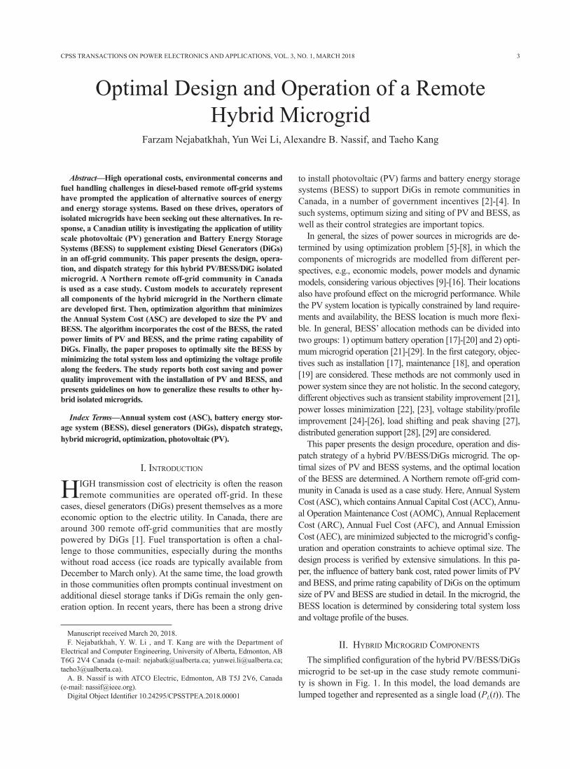
Fig. 3 shows the flowchart of dispatch strategy used in this study. The outcome of this strategy is the output powers of DiGs and BESS, and the amount of excess power and unmet load demand at hour t. It is worth to mention again that the time step in this paper is an hour.
The PV system always tracks its maximum power point (MPP). The PV system output power is assumed constant during each Δt. The BESS is discharged to reduce the num-ber of DiGs start-ups and the system total cost (see in Fig. 3). The BESS is charged whenever enough power can be provided (see in Fig. 3). On the DiGs operation, their operating powers should be within their minimum and max-imum powers range. The DiGs are started-up sequentially
when the output power of PV and running DiGs, along with BESS maximum discharge power cannot meet load demand.
IV. optIMal sIzIng of pV and bessThis section defines the objective function to address the
optimal size of PV and BESS and presents simulation re-sults.
A. Objective Function
The objective function minimizes the Annual System Cost (ASC), to best benchmark the cost analysis. The ASC in-cludes Annual Capital Cost (ACC), Annual Operation Main-tenance Cost (AOMC), Annual Replacement Cost (ARC), Annual Fuel Cost (AFC) of the DiGs, and Annual Emission Cost (AEC) of the DiGs. In the ASC calculations, the PV modules, the PV inverters, the battery banks, the battery con-verters, and the diesel generators are considered. In (9), the ASC is presented:
Fig. 3. Flowchart of dispatch strategy of the hybrid PV/BESS/DiGs micro-grid.
6 CPSS TRANSACTIONS ON POWER ELECTRONICS AND APPLICATIONS, VOL. 3, NO. 1, MARCH 2018
ASC = ACC + AOMC + ARC + AFC + AEC + ADC (9)
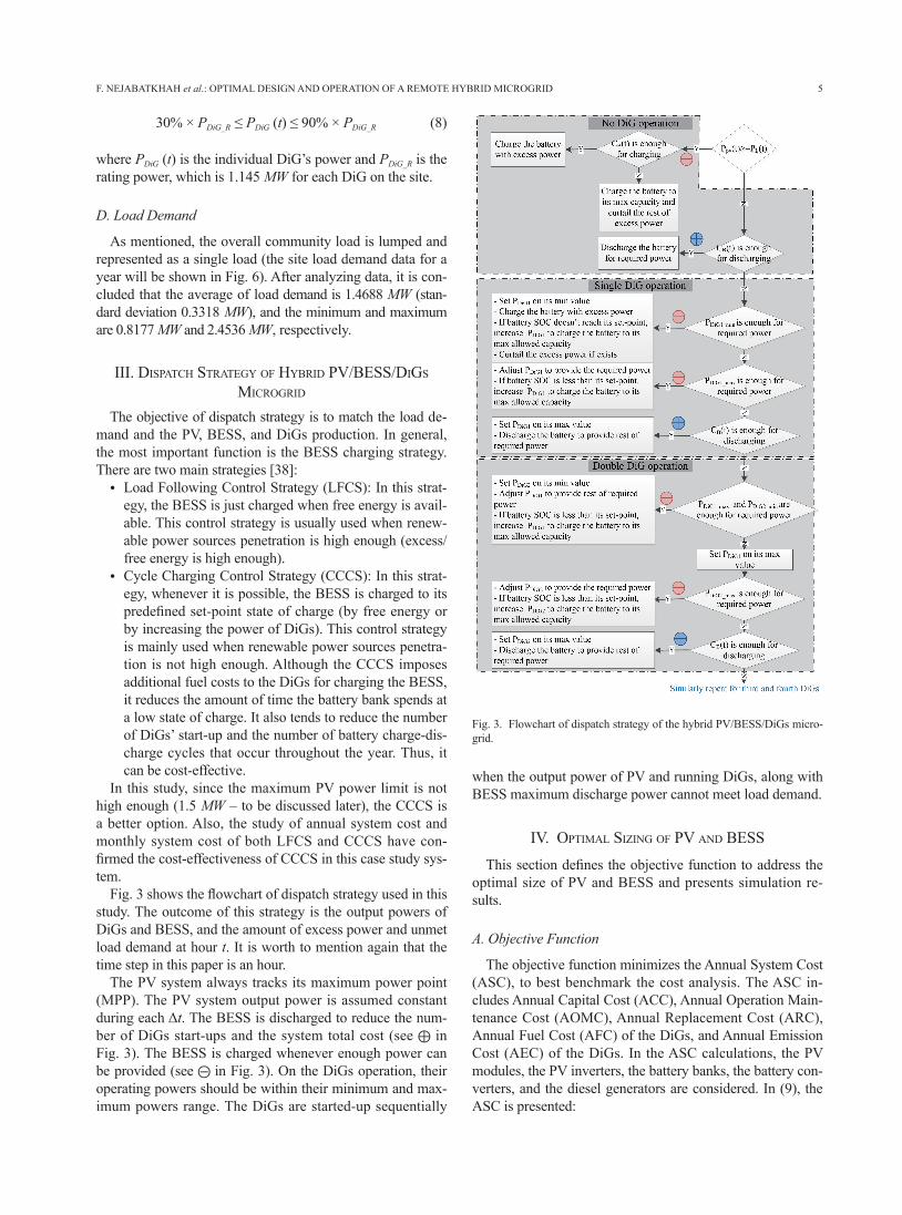
The following describes the aforementioned annual costs [30], [34], [36]-[40]. The parameter values have been pro-vided by the owner and operator of the off-grid microgrid studied in this paper.
1) Annual Capital Cost (ACC)The ACC of each component is calculated using (10).
ACC = Ccap × CRF (i, y) (10)
where Ccap is the each component capital cost in $, y is the project lifetime in year, CRF is the capital recovery cost (a ratio used to calculate the present value of an annuity, a se-ries of equal annual cash flows) and i the is real interest rate (or called real discount rate). The calculations of CRF and i are presented in (11) and (12).
(11)
(12)
where i' is the nominal loan interest (or nominal discount rate) and f is the annual inflation rate. TABLE I lists parame-ters used for the ACC calculation of each component in this paper.
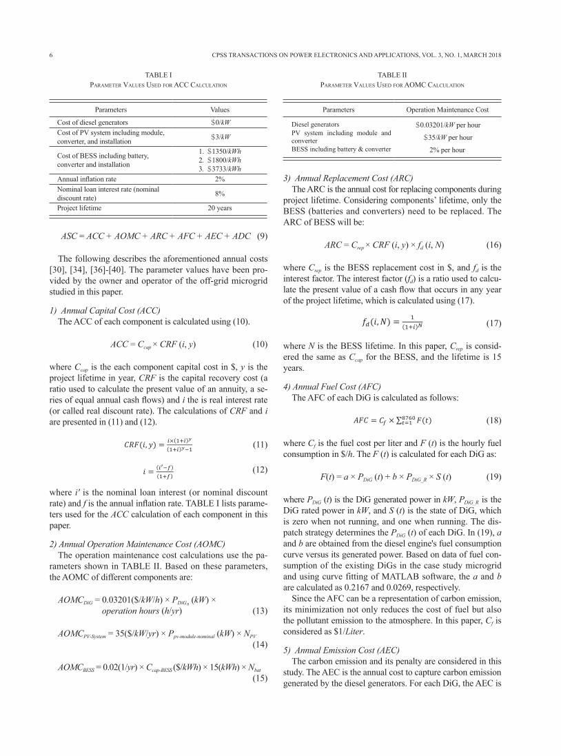
2) Annual Operation Maintenance Cost (AOMC)The operation maintenance cost calculations use the pa-
rameters shown in TABLE II. Based on these parameters, the AOMC of different components are:
AOMCDiG = 0.03201($/kW/h) × PDiG (kW) × operation hours (h/yr) (13)
AOMCPV-System = 35($/kW/yr) × Ppv-module-nominal (kW) × NPV
(14)
AOMCBESS = 0.02(1/yr) × Ccap-BESS ($/kWh) × 15(kWh) × Nbat
(15)
3) Annual Replacement Cost (ARC)The ARC is the annual cost for replacing components during
project lifetime. Considering components’ lifetime, only the BESS (batteries and converters) need to be replaced. The ARC of BESS will be:
ARC = Crep × CRF (i, y) × fd (i, N) (16)
where Crep is the BESS replacement cost in $, and fd is the interest factor. The interest factor (fd) is a ratio used to calcu-late the present value of a cash flow that occurs in any year of the project lifetime, which is calculated using (17).
(17)
where N is the BESS lifetime. In this paper, Crep is consid-ered the same as Ccap for the BESS, and the lifetime is 15 years.
4) Annual Fuel Cost (AFC)The AFC of each DiG is calculated as follows:
(18)
where Cf is the fuel cost per liter and F (t) is the hourly fuel consumption in $/h. The F (t) is calculated for each DiG as:
F(t) = a × PDiG (t) + b × PDiG_R × S (t) (19)
where PDiG (t) is the DiG generated power in kW, PDiG_R is the DiG rated power in kW, and S (t) is the state of DiG, which is zero when not running, and one when running. The dis-patch strategy determines the PDiG (t) of each DiG. In (19), a and b are obtained from the diesel engine's fuel consumption curve versus its generated power. Based on data of fuel con-sumption of the existing DiGs in the case study microgrid and using curve fitting of MATLAB software, the a and b are calculated as 0.2167 and 0.0269, respectively.
Since the AFC can be a representation of carbon emission, its minimization not only reduces the cost of fuel but also the pollutant emission to the atmosphere. In this paper, Cf is considered as $1/Liter.
5) Annual Emission Cost (AEC)The carbon emission and its penalty are considered in this
study. The AEC is the annual cost to capture carbon emission generated by the diesel generators. For each DiG, the AEC is
TABLE IparaMeter Values used for acc calculatIon
Parameters Values
Cost of diesel generators $0/kWCost of PV system including module, converter, and installation $3/kW
Cost of BESS including battery,converter and installation
1. $1350/kWh2. $1800/kWh3. $3733/kWh
Annual inflation rate 2%Nominal loan interest rate (nominaldiscount rate) 8%
Project lifetime 20 years
TABLE IIparaMeter Values used for aoMc calculatIon
Parameters Operation Maintenance Cost
$0.03201/kW per hour
$35/kW per hour
2% per hour
7
calculated as follows:
(20)
where Ef is the emission factor in kg/kWh, and Ecf is the emission cost factor in $/ton. The Ef of DiGs on the site is 0.634 kg/kWh, and Ecf is assumed to be $30/ton (Ecf is referred to carbon tax, which has been effective on Jan. 1, 2017 in Alberta with the price of $20/ton. The price has been raised to $30/ton on Jan. 1, 2018).
B. Constraints
The practical constraints of the optimization problem can be divided into configuration constraints and operation constrains. The configuration constraints are the maximum number of PV modules (Npv_max) and battery banks (Nbat_max). In this paper, the maximum amount of PV power and battery banks were set at 1.5 MW and 750 kWh due to budget con-straints. Since the 340 W PV modules and 15 kWh battery banks are assumed, Npv_max and Nbat_max are 4412 and 50.
The operation constraints are the balance of generated and consumed power, the constraint on the energy level of BESS, and the optimum operating condition of DiGs. All these op-eration constraints are addressed in the dispatch strategy, and are reviewed as:
(21)
(22)
(23)
C. Simulation Results
The components of hybrid microgrid are modeled in MAT-LAB software, and the optimization problem is solved to achieve the optimal number of PV modules and battery banks. T he influences of 1) battery bank cost, 2) PV and BESS maximum powers limits, and 3) prime rating control of the DiGs on optimization results are also studied.
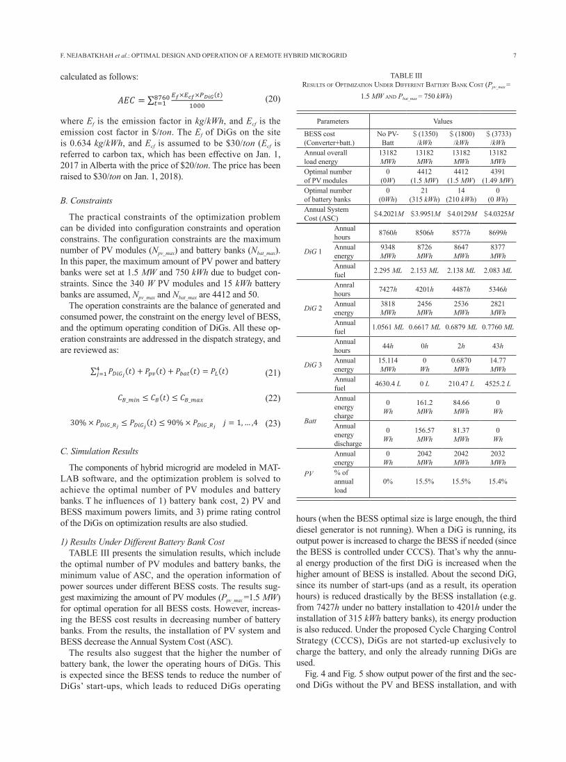
1) Results Under Different Battery Bank CostTABLE III presents the simulation results, which include
the optimal number of PV modules and battery banks, the minimum value of ASC, and the operation information of power sources under different BESS costs. The results sug-gest maximizing the amount of PV modules (Ppv_max =1.5 MW) for optimal operation for all BESS costs. However, increas-ing the BESS cost results in decreasing number of battery banks. From the results, the installation of PV system and BESS decrease the Annual System Cost (ASC).
The results also suggest that the higher the number of battery bank, the lower the operating hours of DiGs. This is expected since the BESS tends to reduce the number of DiGs’ start-ups, which leads to reduced DiGs operating
hours (when the BESS optimal size is large enough, the third diesel generator is not running). When a DiG is running, its output power is increased to charge the BESS if needed (since the BESS is controlled under CCCS). That’s why the annu-al energy production of the first DiG is increased when the higher amount of BESS is installed. About the second DiG, since its number of start-ups (and as a result, its operation hours) is reduced drastically by the BESS installation (e.g. from 7427h under no battery installation to 4201h under the installation of 315 kWh battery banks), its energy production is also reduced. Under the proposed Cycle Charging Control Strategy (CCCS), DiGs are not started-up exclusively to charge the battery, and only the already running DiGs are used.
Fig. 4 and Fig. 5 show output power of the first and the sec-ond DiGs without the PV and BESS installation, and with
F. NEJABATKHAH et al.: OPTIMAL DESIGN AND OPERATION OF A REMOTE HYBRID MICROGRID
TABLE IIIresults of optIMIzatIon under dIfferent battery bank cost (Ppv_max =
1.5 MW and Pbat_max = 750 kWh)
Parameters Values
BESS cost(Converter+batt.)
No PV-Batt
$(1350)/kWh
$(1800)/kWh
$(3733)/kWh
Annual overallload energy
13182MWh
13182MWh
13182MWh
13182MWh
Optimal numberof PV modules
0(0W)
4412(1.5 MW)
4412(1.5 MW)
4391(1.49 MW)
Optimal numberof battery banks
0(0Wh)
21(315 kWh)
14(210 kWh)
0(0 Wh)
Annual SystemCost (ASC) $4.2021M $3.9951M $4.0129M $4.0325M
DiG 1
Annualhours 8760h 8506h 8577h 8699h
Annualenergy
9348MWh
8726MWh
8647MWh
8377MWh
Annualfuel 2.295 ML 2.153 ML 2.138 ML 2.083 ML
DiG 2
Annralhours 7427h 4201h 4487h 5346h
Annualenergy
3818MWh
2456MWh
2536MWh
2821MWh
Annualfuel 1.0561 ML 0.6617 ML 0.6879 ML 0.7760 ML
DiG 3
Annualhours 44h 0h 2h 43h
Annualenergy
15.114MWh
0Wh
0.6870MWh
14.77MWh
Annualfuel 4630.4 L 0 L 210.47 L 4525.2 L
Batt
Annualenergycharge
0Wh
161.2MWh
84.66MWh
0Wh
Annualenergydischarge
0Wh
156.57MWh
81.37MWh
0Wh
PV
Annualenergy
0Wh
2042MWh
2042MWh
2032MWh
% ofannualload
0% 15.5% 15.5% 15.4%
8 CPSS TRANSACTIONS ON POWER ELECTRONICS AND APPLICATIONS, VOL. 3, NO. 1, MARCH 2018
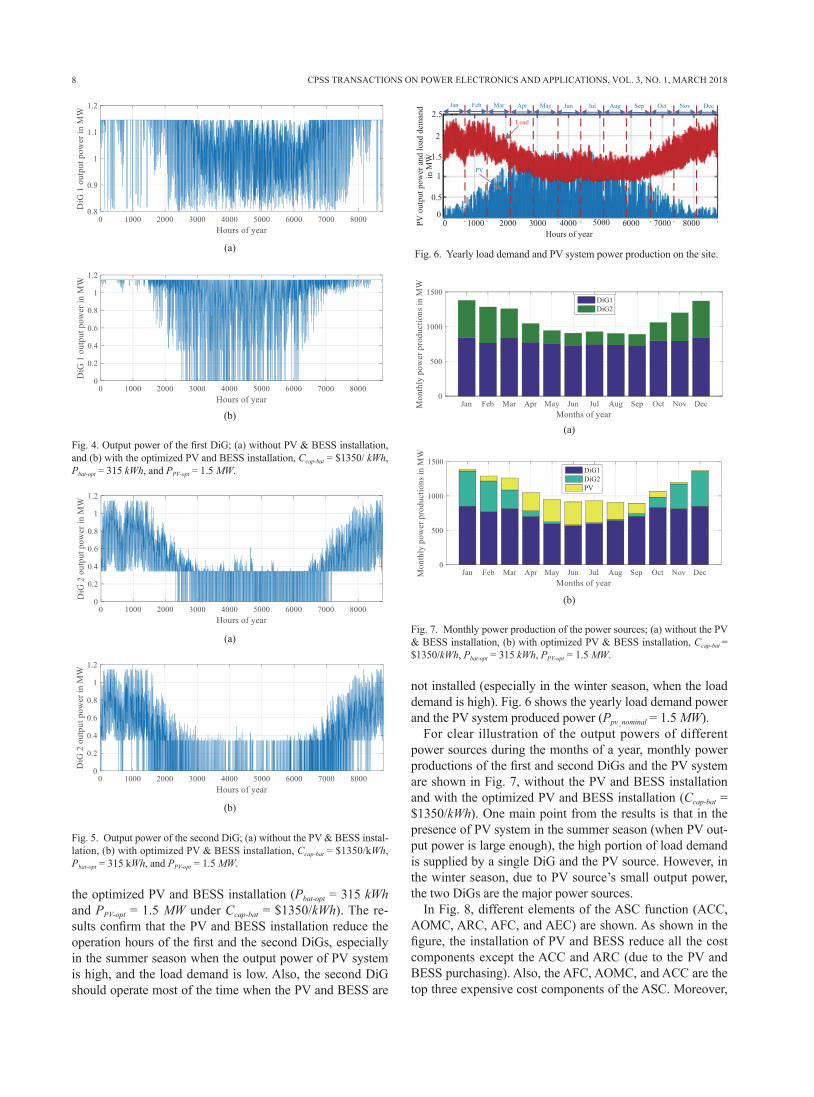
the optimized PV and BESS installation (Pbat-opt = 315 kWh and PPV-opt = 1.5 MW under Ccap-bat = $1350/kWh). The re-sults confirm that the PV and BESS installation reduce the operation hours of the first and the second DiGs, especially in the summer season when the output power of PV system is high, and the load demand is low. Also, the second DiG should operate most of the time when the PV and BESS are
not installed (especially in the winter season, when the load demand is high). Fig. 6 shows the yearly load demand power and the PV system produced power (Ppv_nominal = 1.5 MW).
For clear illustration of the output powers of different power sources during the months of a year, monthly power productions of the first and second DiGs and the PV system are shown in Fig. 7, without the PV and BESS installation and with the optimized PV and BESS installation (Ccap-bat = $1350/kWh). One main point from the results is that in the presence of PV system in the summer season (when PV out-put power is large enough), the high portion of load demand is supplied by a single DiG and the PV source. However, in the winter season, due to PV source’s small output power, the two DiGs are the major power sources.
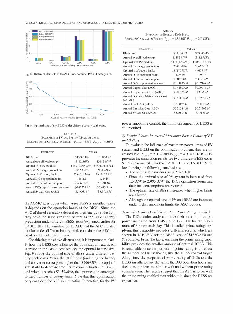
In Fig. 8, different elements of the ASC function (ACC, AOMC, ARC, AFC, and AEC) are shown. As shown in the figure, the installation of PV and BESS reduce all the cost components except the ACC and ARC (due to the PV and BESS purchasing). Also, the AFC, AOMC, and ACC are the top three expensive cost components of the ASC. Moreover,
Fig. 5. Output power of the second DiG; (a) without the PV & BESS instal-lation, (b) with optimized PV & BESS installation, Ccap-bat = $1350/kWh, Pbat-opt = 315 kWh, and PPV-opt = 1.5 MW.
(b)
(a)
Fig. 4. Output power of the first DiG; (a) without PV & BESS installation, and (b) with the optimized PV and BESS installation, Ccap-bat = $1350/ kWh, Pbat-opt = 315 kWh, and PPV-opt = 1.5 MW.
(b)
(a) Fig. 6. Yearly load demand and PV system power production on the site.
Fig. 7. Monthly power production of the power sources; (a) without the PV & BESS installation, (b) with optimized PV & BESS installation, Ccap-bat = $1350/kWh, Pbat-opt = 315 kWh, PPV-opt = 1.5 MW.
(b)
(a)
9
the AOMC goes down when larger BESS is installed (since it depends on the operation hours of the DiGs). Since the AFC of diesel generators depend on their energy production, they have the same variation pattern as the DiGs’ energy production under different BESS costs (explained earlier for TABLE III). The variation of the AEC and the AFC are also similar under different battery bank cost since the AEC de-pend on the fuel consumption.
Considering the above discussions, it is important to clari-fy how the BESS cost influence the optimization results. An increase in the BESS cost reduces the optimal battery size. Fig. 9 shows the optimal size of BESS under different bat-tery bank costs. When the BESS cost (including the battery and converter costs) goes higher than $900/kWh, the optimal size starts to decrease from its maximum limits (750 kWh), and when it reaches $3450/kWh, the optimization converges to zero number of battery bank. Note that this optimization only considers the ASC minimization. In practice, for the PV
power smoothing control, the minimum amount of BESS is still required.
2) Results Under Increased Maximum Power Limits of PV and Battery
To evaluate the influence of maximum power limits of PV system and BESS on the optimization problem, they are in-creased into Ppv_max = 5 MW and Pbat_max = 4 MWh. TABLE IV provides the simulation results for two different BESS costs, $1350/kWh and $1800/kWh. TABLE III and TABLE IV al-low drawing the following conclusions:
● The optimal PV system size is 2.095 MW. ● Since the optimal size of PV system is increased from
1.5 MW to 2.095 MW, the DiGs operation hours and their fuel consumptions are reduced.
● The optimal size of BESS increases when higher limits are allowed.
● Although the optimal size of PV and BESS are increased under higher maximum limits, the ASC reduces.
3) Results Under Diesel Generators Prime Rating EnabledThe DiGs under study can have their maximum output
power increased from 1145 kW to 1280 kW for the maxi-mum of 8 hours each day. This is called prime rating. Ap-plying this capability provides different results, which are shown in TABLE V for the BESS costs of $1350/kWh and $1800/kWh. From the table, enabling the prime rating capa-bility provides the smaller amount of optimal BESS. This is reasonable since the purpose of prime rating is to reduce the number of DiG start-ups, like the BESS control target. Also, since the purposes of prime rating of DiGs and the BESS installation are the same, the DiG operation hours and fuel consumptions are similar with and without prime rating consideration. The results suggest that the ASC is lower with the prime rating enabled than without it, since the BESS are expensive.
F. NEJABATKHAH et al.: OPTIMAL DESIGN AND OPERATION OF A REMOTE HYBRID MICROGRID
Fig. 8. Different elements of the ASC under optimal PV and battery size.
Fig. 9. Optimal size of the BESS under different battery bank costs.
TABLE IVeValuatIon of pV and battery MaxIMuM lIMIts
Increase on tHe optIMIzatIon results; Ppv_max = 5 MW, Pbat_max = 4 MWh
Parameters Values
BESS cost $1350/kWh $1800/kWhAnnual overall load energy 13182 MWh 13182 MWhOptimal # of PV modules 6163 (2.095 MW) 6160 (2.095 MW)Annual PV energy production 2852 MWh 2851 MWhOptimal # of battery banks 27 (405 kWh) 16 (240 kWh)Annual DiGs operation hours 11615h 12144hAnnual DiGs fuel consumption 2.6365 ML 2.6540 MLAnnual DiGs capital maintenance cost $0.42571 M $0.44510 MAnnual System Cost (ASC) $3.9566 M $3.9768 M
TABLE VeValuatIon of enablIng dIgs prIMe
ratIng on optIMIzatIon results (Ppv_max = 1.55 MW, Pbat_max = 750 KWh)
Parameters ValuesBESS cost $1350/kWh $1800/kWhAnnual overall load energy 13182 MWh 13182 MWhOptimal # of PV modules 4412 (1.5 MW) 4410 (1.5 MW)Annual PV energy production 2042 MWh 2042 MWhOptimal # of battery banks 18 (270 kWh) 4 (60 kWh)Annual DiGs operation hours 12297h 12924hAnnual DiGs fuel consumption 2.8037 ML 2.8250 MLAnnual DiGs captial maintenance $0.45070 M $0.47368 MAnnual Capital Cost (ACC) $0.42009 M $0.39776 MAnnual Replacement Cost (ARC) $0.01335 M $3956 MAnnual Operation Maintenance Cost(AOMC) $0.51050 M $0.52832 M
Annual Fuel Cost (AFC) $2.8037 M $2.8250 MAnnual Emission Cost (AEC) $0.21284 M $0.21302 MAnnual System Cost (ACS) $3.9605 M $3.9681 M
10 CPSS TRANSACTIONS ON POWER ELECTRONICS AND APPLICATIONS, VOL. 3, NO. 1, MARCH 2018
D. Discussions
The results presented in this section suggest that:● In each microgrid, there is an optimum amount of PV
power that minimizes the annual system cost, and the high-er PV power installation cannot guarantee the lower ASC.
● The optimal size of BESS directly depends on its capi-tal costs. Increasing the BESS cost leads to the smaller optimum size of BESS.
● Since the BESS reduces the number of DiG start-ups, a larger BESS size leads to fewer operation hours of the DiGs.
● The PV system and the BESS installation reduce all the ASC components except the ACC and ARC (due to the PV and battery initial costs).
● The Annual Fuel Cost (AFC) of diesel generators, the Annual Operation Maintenance Cost (AOMC), and the Annual Capital Cost (ACC) are the most expensive cost components of the ASC.
● Since the Annual Operation Maintenance Cost (AOMC) of diesel generators depend on their operation hours, it goes down when larger amount of the BESS is installed.
● Since the Annual Fuel Cost (AFC) of DiGs depends on their energy production, it will go down in the presence of PV and BESS.
● The diesel generators are the most expensive compo-nents of hybrid microgrid. Their costs go beyond that of an engine and alternator. The cost of building, fuel storage tank, and maintenance must also be considered.
● Enabling the prime rating capability of DiGs results in smaller optimal size of the BESS since it takes the BESS responsibility in reducing the number of DiGs start-ups.
V. allocatIon of tHe pV and bessIn this study, the installation location of PV system was
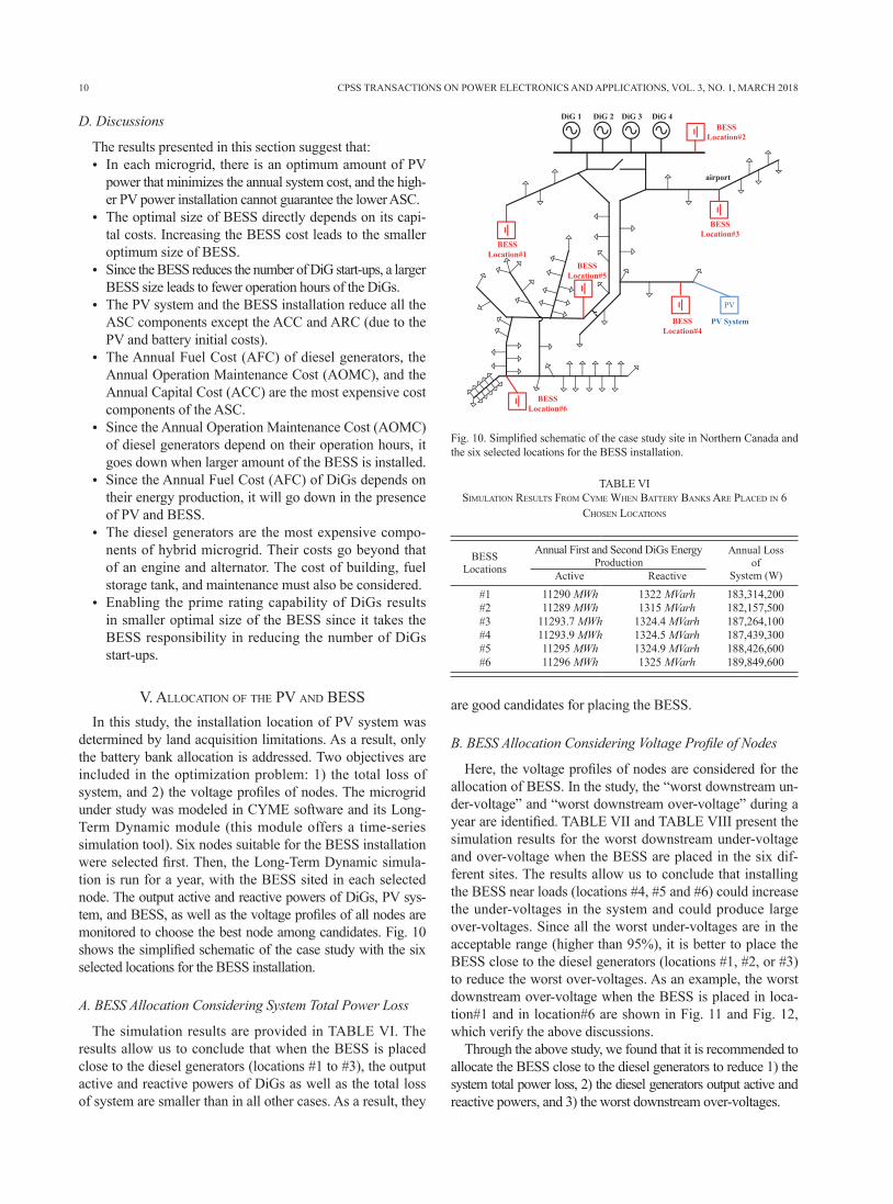
determined by land acquisition limitations. As a result, only the battery bank allocation is addressed. Two objectives are included in the optimization problem: 1) the total loss of system, and 2) the voltage profiles of nodes. The microgrid under study was modeled in CYME software and its Long-Term Dynamic module (this module offers a time-series simulation tool). Six nodes suitable for the BESS installation were selected first. Then, the Long-Term Dynamic simula-tion is run for a year, with the BESS sited in each selected node. The output active and reactive powers of DiGs, PV sys-tem, and BESS, as well as the voltage profiles of all nodes are monitored to choose the best node among candidates. Fig. 10 shows the simplified schematic of the case study with the six selected locations for the BESS installation.
A. BESS Allocation Considering System Total Power Loss
The simulation results are provided in TABLE VI. The results allow us to conclude that when the BESS is placed close to the diesel generators (locations #1 to #3), the output active and reactive powers of DiGs as well as the total loss of system are smaller than in all other cases. As a result, they
are good candidates for placing the BESS.
B. BESS Allocation Considering Voltage Profile of Nodes
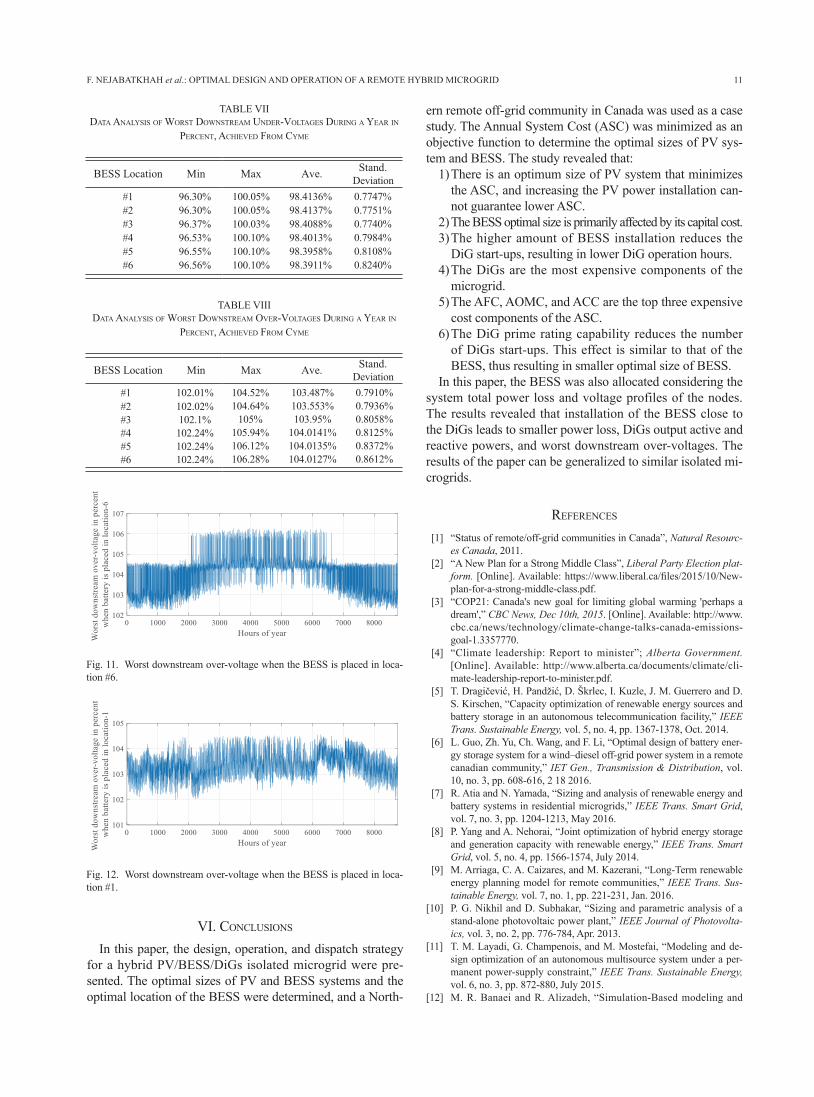
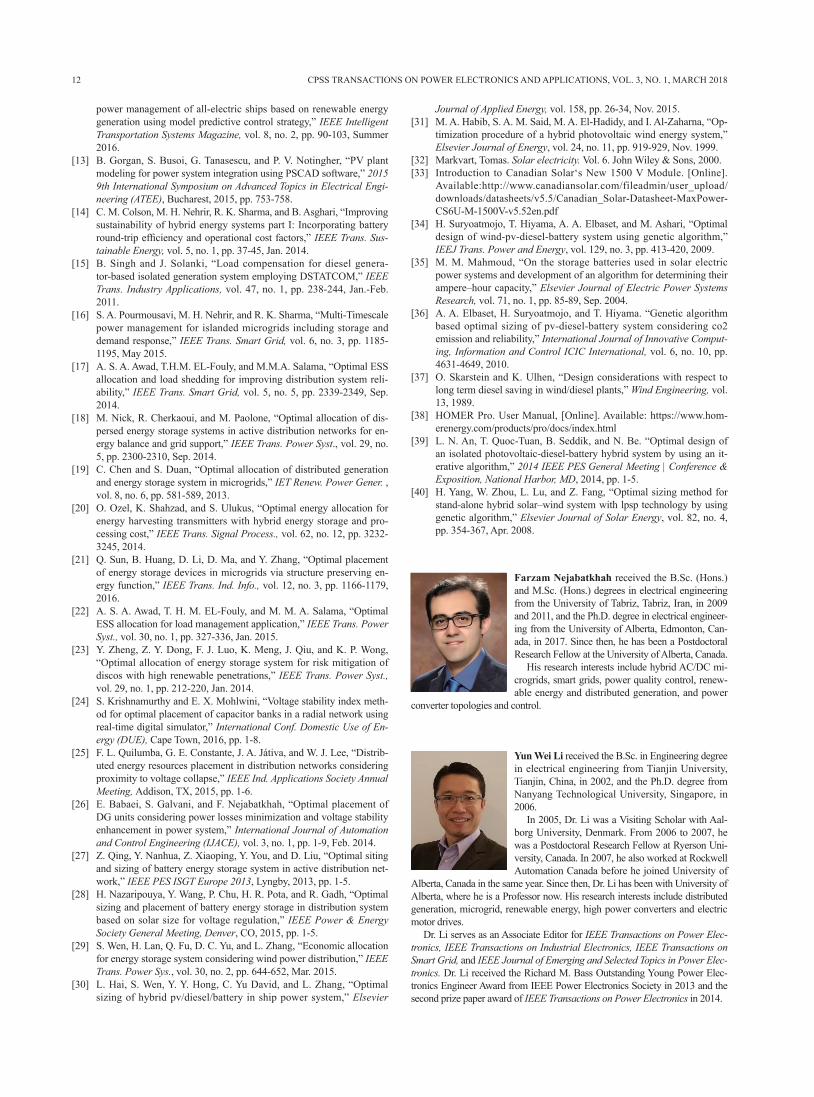
Here, the voltage profiles of nodes are considered for the allocation of BESS. In the study, the “worst downstream un-der-voltage” and “worst downstream over-voltage” during a year are identified. TABLE VII and TABLE VIII present the simulation results for the worst downstream under-voltage and over-voltage when the BESS are placed in the six dif-ferent sites. The results allow us to conclude that installing the BESS near loads (locations #4, #5 and #6) could increase the under-voltages in the system and could produce large over-voltages. Since all the worst under-voltages are in the acceptable range (higher than 95%), it is better to place the BESS close to the diesel generators (locations #1, #2, or #3) to reduce the worst over-voltages. As an example, the worst downstream over-voltage when the BESS is placed in loca-tion#1 and in location#6 are shown in Fig. 11 and Fig. 12, which verify the above discussions.
Through the above study, we found that it is recommended to allocate the BESS close to the diesel generators to reduce 1) the system total power loss, 2) the diesel generators output active and reactive powers, and 3) the worst downstream over-voltages.
Fig. 10. Simplified schematic of the case study site in Northern Canada and the six selected locations for the BESS installation.
TABLE VIsIMulatIon results froM cyMe WHen battery banks are placed In 6
cHosen locatIons
11290 MWh11289 MWh
11293.7 MWh11293.9 MWh11295 MWh11296 MWh
1322 MVarh1315 MVarh
1324.4 MVarh1324.5 MVarh1324.9 MVarh1325 MVarh
183,314,200182,157,500187,264,100187,439,300188,426,600189,849,600
#1#2#3#4#5#6
Annual First and Second DiGs Energy
11
VI. conclusIons In this paper, the design, operation, and dispatch strategy
for a hybrid PV/BESS/DiGs isolated microgrid were pre-sented. The optimal sizes of PV and BESS systems and the optimal location of the BESS were determined, and a North-
ern remote off-grid community in Canada was used as a case study. The Annual System Cost (ASC) was minimized as an objective function to determine the optimal sizes of PV sys-tem and BESS. The study revealed that:
1) There is an optimum size of PV system that minimizes the ASC, and increasing the PV power installation can-not guarantee lower ASC.
2) The BESS optimal size is primarily affected by its capital cost. 3) The higher amount of BESS installation reduces the
DiG start-ups, resulting in lower DiG operation hours. 4) The DiGs are the most expensive components of the
microgrid. 5) The AFC, AOMC, and ACC are the top three expensive
cost components of the ASC.6) The DiG prime rating capability reduces the number
of DiGs start-ups. This effect is similar to that of the BESS, thus resulting in smaller optimal size of BESS.
In this paper, the BESS was also allocated considering the system total power loss and voltage profiles of the nodes. The results revealed that installation of the BESS close to the DiGs leads to smaller power loss, DiGs output active and reactive powers, and worst downstream over-voltages. The results of the paper can be generalized to similar isolated mi-crogrids.
references
[1] “Status of remote/off-grid communities in Canada”, Natural Resourc-es Canada, 2011.
[2] “A New Plan for a Strong Middle Class”, Liberal Party Election plat-form. [Online]. Available: https://www.liberal.ca/files/2015/10/New-plan-for-a-strong-middle-class.pdf.
[3] “COP21: Canada's new goal for limiting global warming 'perhaps a dream',” CBC News, Dec 10th, 2015. [Online]. Available: http://www.cbc.ca/news/technology/climate-change-talks-canada-emissions-goal-1.3357770.
[4] “Climate leadership: Report to minister”; Alberta Government. [Online]. Available: http://www.alberta.ca/documents/climate/cli-mate-leadership-report-to-minister.pdf.
[5] T. Dragičević, H. Pandžić, D. Škrlec, I. Kuzle, J. M. Guerrero and D. S. Kirschen, “Capacity optimization of renewable energy sources and battery storage in an autonomous telecommunication facility,” IEEE Trans. Sustainable Energy, vol. 5, no. 4, pp. 1367-1378, Oct. 2014.
[6] L. Guo, Zh. Yu, Ch. Wang, and F. Li, “Optimal design of battery ener-gy storage system for a wind–diesel off-grid power system in a remote canadian community,” IET Gen., Transmission & Distribution, vol. 10, no. 3, pp. 608-616, 2 18 2016.
[7] R. Atia and N. Yamada, “Sizing and analysis of renewable energy and battery systems in residential microgrids,” IEEE Trans. Smart Grid, vol. 7, no. 3, pp. 1204-1213, May 2016.
[8] P. Yang and A. Nehorai, “Joint optimization of hybrid energy storage and generation capacity with renewable energy,” IEEE Trans. Smart Grid, vol. 5, no. 4, pp. 1566-1574, July 2014.
[9] M. Arriaga, C. A. Caizares, and M. Kazerani, “Long-Term renewable energy planning model for remote communities,” IEEE Trans. Sus-tainable Energy, vol. 7, no. 1, pp. 221-231, Jan. 2016.
[10] P. G. Nikhil and D. Subhakar, “Sizing and parametric analysis of a stand-alone photovoltaic power plant,” IEEE Journal of Photovolta-ics, vol. 3, no. 2, pp. 776-784, Apr. 2013.
[11] T. M. Layadi, G. Champenois, and M. Mostefai, “Modeling and de-sign optimization of an autonomous multisource system under a per-manent power-supply constraint,” IEEE Trans. Sustainable Energy, vol. 6, no. 3, pp. 872-880, July 2015.
[12] M. R. Banaei and R. Alizadeh, “Simulation-Based modeling and
F. NEJABATKHAH et al.: OPTIMAL DESIGN AND OPERATION OF A REMOTE HYBRID MICROGRID
Fig. 11. Worst downstream over-voltage when the BESS is placed in loca-tion #6.
Fig. 12. Worst downstream over-voltage when the BESS is placed in loca-tion #1.
TABLE VIIIdata analysIs of Worst doWnstreaM oVer-Voltages durIng a year In
percent, acHIeVed froM cyMe
TABLE VIIdata analysIs of Worst doWnstreaM under-Voltages durIng a year In
percent, acHIeVed froM cyMe
0.7747%0.7751%0.7740%0.7984%0.8108%0.8240%
0.7910%0.7936%0.8058%0.8125%0.8372%0.8612%
98.4136%98.4137%98.4088%98.4013%98.3958%98.3911%
103.487%103.553%103.95%
104.0141%104.0135%104.0127%
100.05%100.05%100.03%100.10%100.10%100.10%
104.52%104.64%
105%105.94%106.12%106.28%
96.30%96.30%96.37%96.53%96.55%96.56%
102.01%102.02%102.1%102.24%102.24%102.24%
#1#2#3#4#5#6
#1#2#3#4#5#6
Deviation
Deviation
12 CPSS TRANSACTIONS ON POWER ELECTRONICS AND APPLICATIONS, VOL. 3, NO. 1, MARCH 2018
power management of all-electric ships based on renewable energy generation using model predictive control strategy,” IEEE Intelligent Transportation Systems Magazine, vol. 8, no. 2, pp. 90-103, Summer 2016.
[13] B. Gorgan, S. Busoi, G. Tanasescu, and P. V. Notingher, “PV plant modeling for power system integration using PSCAD software,” 2015 9th International Symposium on Advanced Topics in Electrical Engi-neering (ATEE), Bucharest, 2015, pp. 753-758.
[14] C. M. Colson, M. H. Nehrir, R. K. Sharma, and B. Asghari, “Improving sustainability of hybrid energy systems part I: Incorporating battery round-trip efficiency and operational cost factors,” IEEE Trans. Sus-tainable Energy, vol. 5, no. 1, pp. 37-45, Jan. 2014.
[15] B. Singh and J. Solanki, “Load compensation for diesel genera-tor-based isolated generation system employing DSTATCOM,” IEEE Trans. Industry Applications, vol. 47, no. 1, pp. 238-244, Jan.-Feb. 2011.
[16] S. A. Pourmousavi, M. H. Nehrir, and R. K. Sharma, “Multi-Timescale power management for islanded microgrids including storage and demand response,” IEEE Trans. Smart Grid, vol. 6, no. 3, pp. 1185-1195, May 2015.
[17] A. S. A. Awad, T.H.M. EL-Fouly, and M.M.A. Salama, “Optimal ESS allocation and load shedding for improving distribution system reli-ability,” IEEE Trans. Smart Grid, vol. 5, no. 5, pp. 2339-2349, Sep. 2014.
[18] M. Nick, R. Cherkaoui, and M. Paolone, “Optimal allocation of dis-persed energy storage systems in active distribution networks for en-ergy balance and grid support,” IEEE Trans. Power Syst., vol. 29, no. 5, pp. 2300-2310, Sep. 2014.
[19] C. Chen and S. Duan, “Optimal allocation of distributed generation and energy storage system in microgrids,” IET Renew. Power Gener. , vol. 8, no. 6, pp. 581-589, 2013.
[20] O. Ozel, K. Shahzad, and S. Ulukus, “Optimal energy allocation for energy harvesting transmitters with hybrid energy storage and pro-cessing cost,” IEEE Trans. Signal Process., vol. 62, no. 12, pp. 3232-3245, 2014.
[21] Q. Sun, B. Huang, D. Li, D. Ma, and Y. Zhang, “Optimal placement of energy storage devices in microgrids via structure preserving en-ergy function,” IEEE Trans. Ind. Info., vol. 12, no. 3, pp. 1166-1179, 2016.
[22] A. S. A. Awad, T. H. M. EL-Fouly, and M. M. A. Salama, “Optimal ESS allocation for load management application,” IEEE Trans. Power Syst., vol. 30, no. 1, pp. 327-336, Jan. 2015.
[23] Y. Zheng, Z. Y. Dong, F. J. Luo, K. Meng, J. Qiu, and K. P. Wong, “Optimal allocation of energy storage system for risk mitigation of discos with high renewable penetrations,” IEEE Trans. Power Syst., vol. 29, no. 1, pp. 212-220, Jan. 2014.
[24] S. Krishnamurthy and E. X. Mohlwini, “Voltage stability index meth-od for optimal placement of capacitor banks in a radial network using real-time digital simulator,” International Conf. Domestic Use of En-ergy (DUE), Cape Town, 2016, pp. 1-8.
[25] F. L. Quilumba, G. E. Constante, J. A. Játiva, and W. J. Lee, “Distrib-uted energy resources placement in distribution networks considering proximity to voltage collapse,” IEEE Ind. Applications Society Annual Meeting, Addison, TX, 2015, pp. 1-6.
[26] E. Babaei, S. Galvani, and F. Nejabatkhah, “Optimal placement of DG units considering power losses minimization and voltage stability enhancement in power system,” International Journal of Automation and Control Engineering (IJACE), vol. 3, no. 1, pp. 1-9, Feb. 2014.
[27] Z. Qing, Y. Nanhua, Z. Xiaoping, Y. You, and D. Liu, “Optimal siting and sizing of battery energy storage system in active distribution net-work,” IEEE PES ISGT Europe 2013, Lyngby, 2013, pp. 1-5.
[28] H. Nazaripouya, Y. Wang, P. Chu, H. R. Pota, and R. Gadh, “Optimal sizing and placement of battery energy storage in distribution system based on solar size for voltage regulation,” IEEE Power & Energy Society General Meeting, Denver, CO, 2015, pp. 1-5.
[29] S. Wen, H. Lan, Q. Fu, D. C. Yu, and L. Zhang, “Economic allocation for energy storage system considering wind power distribution,” IEEE Trans. Power Sys., vol. 30, no. 2, pp. 644-652, Mar. 2015.
[30] L. Hai, S. Wen, Y. Y. Hong, C. Yu David, and L. Zhang, “Optimal sizing of hybrid pv/diesel/battery in ship power system,” Elsevier
Journal of Applied Energy, vol. 158, pp. 26-34, Nov. 2015. [31] M. A. Habib, S. A. M. Said, M. A. El-Hadidy, and I. Al-Zaharna, “Op-
timization procedure of a hybrid photovoltaic wind energy system,” Elsevier Journal of Energy, vol. 24, no. 11, pp. 919-929, Nov. 1999.
[32] Markvart, Tomas. Solar electricity. Vol. 6. John Wiley & Sons, 2000.[33] Introduction to Canadian Solar‘s New 1500 V Module. [Online].
Available:http://www.canadiansolar.com/fileadmin/user_upload/downloads/datasheets/v5.5/Canadian_Solar-Datasheet-MaxPower-CS6U-M-1500V-v5.52en.pdf
[34] H. Suryoatmojo, T. Hiyama, A. A. Elbaset, and M. Ashari, “Optimal design of wind-pv-diesel-battery system using genetic algorithm,” IEEJ Trans. Power and Energy, vol. 129, no. 3, pp. 413-420, 2009.
[35] M. M. Mahmoud, “On the storage batteries used in solar electric power systems and development of an algorithm for determining their ampere–hour capacity,” Elsevier Journal of Electric Power Systems Research, vol. 71, no. 1, pp. 85-89, Sep. 2004.
[36] A. A. Elbaset, H. Suryoatmojo, and T. Hiyama. “Genetic algorithm based optimal sizing of pv-diesel-battery system considering co2 emission and reliability,” International Journal of Innovative Comput-ing, Information and Control ICIC International, vol. 6, no. 10, pp. 4631-4649, 2010.
[37] O. Skarstein and K. Ulhen, “Design considerations with respect to long term diesel saving in wind/diesel plants,” Wind Engineering, vol. 13, 1989.
[38] HOMER Pro. User Manual, [Online]. Available: https://www.hom-erenergy.com/products/pro/docs/index.html
[39] L. N. An, T. Quoc-Tuan, B. Seddik, and N. Be. “Optimal design of an isolated photovoltaic-diesel-battery hybrid system by using an it-erative algorithm,” 2014 IEEE PES General Meeting | Conference & Exposition, National Harbor, MD, 2014, pp. 1-5.
[40] H. Yang, W. Zhou, L. Lu, and Z. Fang, “Optimal sizing method for stand-alone hybrid solar–wind system with lpsp technology by using genetic algorithm,” Elsevier Journal of Solar Energy, vol. 82, no. 4, pp. 354-367, Apr. 2008.
Farzam Nejabatkhah received the B.Sc. (Hons.) and M.Sc. (Hons.) degrees in electrical engineering from the University of Tabriz, Tabriz, Iran, in 2009 and 2011, and the Ph.D. degree in electrical engineer-ing from the University of Alberta, Edmonton, Can-ada, in 2017. Since then, he has been a Postdoctoral Research Fellow at the University of Alberta, Canada.
His research interests include hybrid AC/DC mi-crogrids, smart grids, power quality control, renew-able energy and distributed generation, and power
converter topologies and control.
Yun Wei Li received the B.Sc. in Engineering degree in electrical engineering from Tianjin University, Tianjin, China, in 2002, and the Ph.D. degree from Nanyang Technological University, Singapore, in 2006.
In 2005, Dr. Li was a Visiting Scholar with Aal-borg University, Denmark. From 2006 to 2007, he was a Postdoctoral Research Fellow at Ryerson Uni-versity, Canada. In 2007, he also worked at Rockwell Automation Canada before he joined University of
Alberta, Canada in the same year. Since then, Dr. Li has been with University of Alberta, where he is a Professor now. His research interests include distributed generation, microgrid, renewable energy, high power converters and electric motor drives.
Dr. Li serves as an Associate Editor for IEEE Transactions on Power Elec-tronics, IEEE Transactions on Industrial Electronics, IEEE Transactions on Smart Grid, and IEEE Journal of Emerging and Selected Topics in Power Elec-tronics. Dr. Li received the Richard M. Bass Outstanding Young Power Elec-tronics Engineer Award from IEEE Power Electronics Society in 2013 and the second prize paper award of IEEE Transactions on Power Electronics in 2014.

13
Alexandre B. Nassif received the Ph.D. degree in Electrical Engineering from the University of Alberta, Edmonton, AB, in 2009. Between 2009 and 2012 he worked for Hydro One Networks, Toronto, ON, as a Protection and Control Planning Engineer. He simul-taneously worked as a postdoctoral Fellow at Ryerson University from 2010 to 2011. He joined ATCO Elec-tric in 2012 and is currently a Specialist Engineer, in charge of Power Quality and DER Interconnection, in the Distribution Planning department. His current
research interests are Power Quality, Distributed Energy Resources and Power System Protection.
Taeho Kang received B.Sc. in electrical engineering from University of Alberta, Edmonton, Canada, in 2016, where he is currently working toward the M.Sc. degree in electrical engineering. His research interests include renewable energy distributed generation, AC microgrids optimization, power converter control, and smart grids.
F. NEJABATKHAH et al.: OPTIMAL DESIGN AND OPERATION OF A REMOTE HYBRID MICROGRID