Embed Size (px)
Citation preview
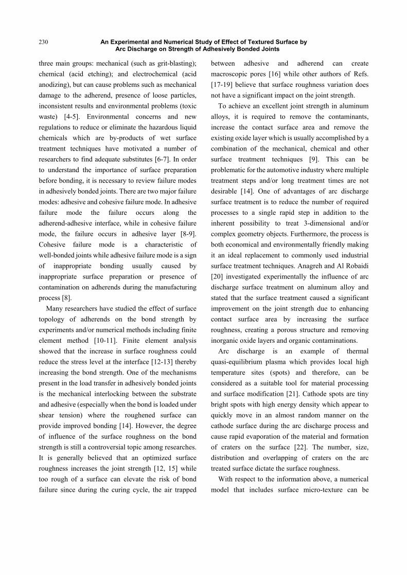
Journal of Mechanics Engineering and Automation 2 (2012) 229-242
An Experimental and Numerical Study of Effect of Textured Surface by Arc Discharge on Strength of Adhesively Bonded Joints
Mehdi Asgharifar1, Fanrong Kong1, Blair Carlson2 and Radovan Kovacevic1 1. Research Center for Advanced Manufacturing (RCAM), Department of Mechanical Engineering, Southern Methodist University,
Dallas TX, USA
2. General Motors R&D, Warren, MI, USA
Received: March 06, 2012 / Accepted: March 19, 2012 / Published: April 25, 2012.
Abstract: Aluminum alloys are being increasingly applied in the automotive industry as a means to reduce mass. Their application to the vehicle structure is typically via a combination of either mechanical or fusion joining with adhesive bonding. Correspondingly, there has been a large effort in improving the adhesive bonding characteristics by changing the surface properties using different surface treatment techniques. One such method is the atmospheric arc discharge process which develops a specific surface roughness which can be leveraged to improve adhesive bonding. In this paper the effect of a textured surface by arc discharge on the failure mode and strength of adhesively bonded aluminum alloy sheets is investigated. A single-lap joint configuration is used for simulation and experimental analysis. A two-dimensional (2D) finite element method (FEM) involving the morphology of treated surfaces and using interfacial elements based on a cohesive zone model (CZM) are used to predict the joint strength which is an enabler for faster product development cycles. The influence of arc process parameters: the arc current and the torch scanning speed, on the surface morphology and joint strength are explored in this study. Specifically, the present study shows that the surface treatment of aluminum alloys by arc discharge can strongly enhance adhesive bond strength. Additionally, arc treatment not only increases the joint strength but also improves the quality of bond along the interface (transition toward cohesive failure mode). The current FE simulation of adhesive joint using the elastic and elasto-plastic (non-linear) material properties for adherend and adhesive, respectively, and cohesive zone elements for interface shows an accurate prediction of the resulting joint strength. By inclusion of non-linear multi-scale geometry model via considering the surface topographical changes after surface treatment the FE joint strength prediction can be successfully implemented. Key words: Adhesive bonding, finite element analysis, arc discharge, surface treatment, aluminum alloys.
1. Introduction
The aircraft industry was one of the first industries that adopted adhesive bonding in aircraft manufacturing for aluminum alloys. Currently, aluminum alloys are the center of attention of auto manufacturers because of their mass savings potential and good mechanical properties making them an appropriate alternative to steel [1-2]. Reducing vehicle mass lowers the fuel
Corresponding author: Radovan Kovacevic, Ph.D., FASME, FSME, FAWS, Herman Brown Chair in Engineering, professor, research director, research fields: materials science and manufacturing engineering. E-mail: [email protected].
consumption and related CO2 emissions which are important factors for the automotive industry. The significant growth in aluminum alloy consumption in the past decade and a parallel growth in the use of adhesives makes aluminum alloys an ideal substrate for adhesive bonding research. There has been large effort in improving the adhesive bonding characteristics by changing the surface properties using different surface treatment techniques. A surface treatment is considered as a crucial factor in adhesive bonding that can influence the joint strength [3]. Common industrially used surface treatment methods can be categorized into
DAVID PUBLISHING
D
An Experimental and Numerical Study of Effect of Textured Surface by Arc Discharge on Strength of Adhesively Bonded Joints
230
three main groups: mechanical (such as grit-blasting); chemical (acid etching); and electrochemical (acid anodizing), but can cause problems such as mechanical damage to the adherend, presence of loose particles, inconsistent results and environmental problems (toxic waste) [4-5]. Environmental concerns and new regulations to reduce or eliminate the hazardous liquid chemicals which are by-products of wet surface treatment techniques have motivated a number of researchers to find adequate substitutes [6-7]. In order to understand the importance of surface preparation before bonding, it is necessary to review failure modes in adhesively bonded joints. There are two major failure modes: adhesive and cohesive failure mode. In adhesive failure mode the failure occurs along the adherend-adhesive interface, while in cohesive failure mode, the failure occurs in adhesive layer [8-9]. Cohesive failure mode is a characteristic of well-bonded joints while adhesive failure mode is a sign of inappropriate bonding usually caused by inappropriate surface preparation or presence of contamination on adherends during the manufacturing process [8].
Many researchers have studied the effect of surface topology of adherends on the bond strength by experiments and/or numerical methods including finite element method [10-11]. Finite element analysis showed that the increase in surface roughness could reduce the stress level at the interface [12-13] thereby increasing the bond strength. One of the mechanisms present in the load transfer in adhesively bonded joints is the mechanical interlocking between the substrate and adhesive (especially when the bond is loaded under shear tension) where the roughened surface can provide improved bonding [14]. However, the degree of influence of the surface roughness on the bond strength is still a controversial topic among researches. It is generally believed that an optimized surface roughness increases the joint strength [12, 15] while too rough of a surface can elevate the risk of bond failure since during the curing cycle, the air trapped
between adhesive and adherend can create macroscopic pores [16] while other authors of Refs. [17-19] believe that surface roughness variation does not have a significant impact on the joint strength.
To achieve an excellent joint strength in aluminum alloys, it is required to remove the contaminants, increase the contact surface area and remove the existing oxide layer which is usually accomplished by a combination of the mechanical, chemical and other surface treatment techniques [9]. This can be problematic for the automotive industry where multiple treatment steps and/or long treatment times are not desirable [14]. One of advantages of arc discharge surface treatment is to reduce the number of required processes to a single rapid step in addition to the inherent possibility to treat 3-dimensional and/or complex geometry objects. Furthermore, the process is both economical and environmentally friendly making it an ideal replacement to commonly used industrial surface treatment techniques. Anagreh and Al Robaidi [20] investigated experimentally the influence of arc discharge surface treatment on aluminum alloy and stated that the surface treatment caused a significant improvement on the joint strength due to enhancing contact surface area by increasing the surface roughness, creating a porous structure and removing inorganic oxide layers and organic contaminations.
Arc discharge is an example of thermal quasi-equilibrium plasma which provides local high temperature sites (spots) and therefore, can be considered as a suitable tool for material processing and surface modification [21]. Cathode spots are tiny bright spots with high energy density which appear to quickly move in an almost random manner on the cathode surface during the arc discharge process and cause rapid evaporation of the material and formation of craters on the surface [22]. The number, size, distribution and overlapping of craters on the arc treated surface dictate the surface roughness.
With respect to the information above, a numerical model that includes surface micro-texture can be
An Experimental and Numerical Study of Effect of Textured Surface by Arc Discharge on Strength of Adhesively Bonded Joints
231
beneficial to study the stress/strain distribution in adhesively bonded joints and prediction of the joint strength. The objective of the present study is to quantify the influence of the surface topology modification in aluminum alloys, caused by the atmospheric-pressure plasma arc discharge, on a single lap shear joint strength using a Finite Element analysis and a series of experiments to verify the results. For this purpose an accurate geometric model of the interface is built based upon the experimental results from surface topology mapping using an optical profilometer. The paper is organized as follows: Section 2 describes the experimental procedure. Section 3 explains the numerical analysis. Section 4 discusses the experimental and numerical and analytical analysis results. Section 5 gives the conclusion. Section 6 states future work.
2. Experimental Procedure
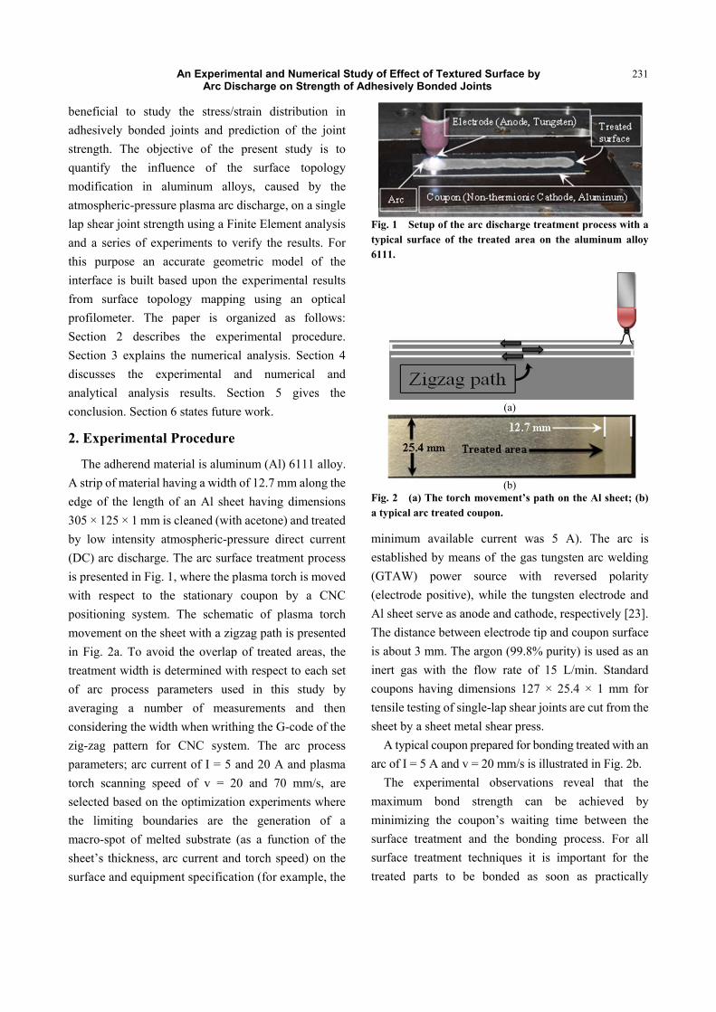
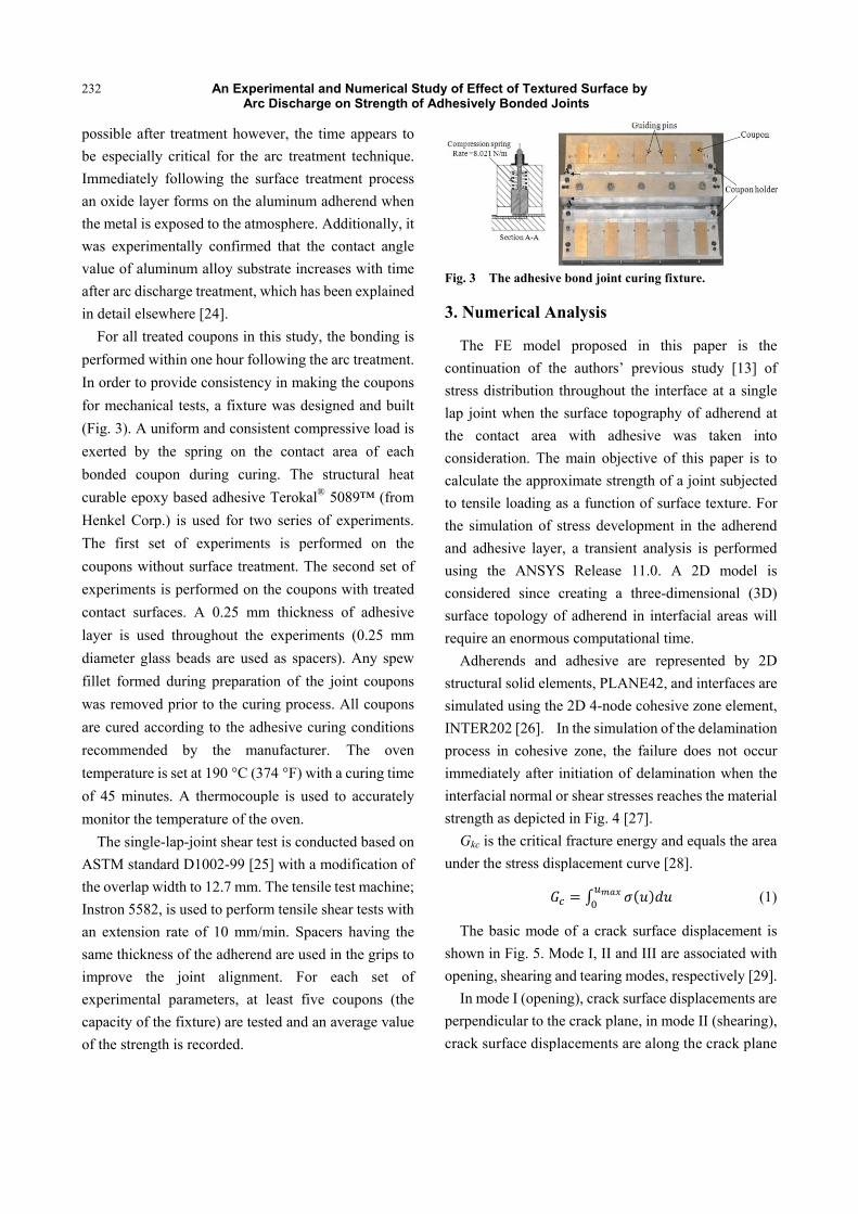
The adherend material is aluminum (Al) 6111 alloy. A strip of material having a width of 12.7 mm along the edge of the length of an Al sheet having dimensions 305 × 125 × 1 mm is cleaned (with acetone) and treated by low intensity atmospheric-pressure direct current (DC) arc discharge. The arc surface treatment process is presented in Fig. 1, where the plasma torch is moved with respect to the stationary coupon by a CNC positioning system. The schematic of plasma torch movement on the sheet with a zigzag path is presented in Fig. 2a. To avoid the overlap of treated areas, the treatment width is determined with respect to each set of arc process parameters used in this study by averaging a number of measurements and then considering the width when writhing the G-code of the zig-zag pattern for CNC system. The arc process parameters; arc current of I = 5 and 20 A and plasma torch scanning speed of v = 20 and 70 mm/s, are selected based on the optimization experiments where the limiting boundaries are the generation of a macro-spot of melted substrate (as a function of the sheet�’s thickness, arc current and torch speed) on the surface and equipment specification (for example, the
Fig. 1 Setup of the arc discharge treatment process with a typical surface of the treated area on the aluminum alloy 6111.
(a)
(b)
Fig. 2 (a) The torch movement�’s path on the Al sheet; (b) a typical arc treated coupon.
minimum available current was 5 A). The arc is established by means of the gas tungsten arc welding (GTAW) power source with reversed polarity (electrode positive), while the tungsten electrode and Al sheet serve as anode and cathode, respectively [23]. The distance between electrode tip and coupon surface is about 3 mm. The argon (99.8% purity) is used as an inert gas with the flow rate of 15 L/min. Standard coupons having dimensions 127 × 25.4 × 1 mm for tensile testing of single-lap shear joints are cut from the sheet by a sheet metal shear press.
A typical coupon prepared for bonding treated with an arc of I = 5 A and v = 20 mm/s is illustrated in Fig. 2b.
The experimental observations reveal that the maximum bond strength can be achieved by minimizing the coupon�’s waiting time between the surface treatment and the bonding process. For all surface treatment techniques it is important for the treated parts to be bonded as soon as practically
An Experimental and Numerical Study of Effect of Textured Surface by Arc Discharge on Strength of Adhesively Bonded Joints
232
possible after treatment however, the time appears to be especially critical for the arc treatment technique. Immediately following the surface treatment process an oxide layer forms on the aluminum adherend when the metal is exposed to the atmosphere. Additionally, it was experimentally confirmed that the contact angle value of aluminum alloy substrate increases with time after arc discharge treatment, which has been explained in detail elsewhere [24].
For all treated coupons in this study, the bonding is performed within one hour following the arc treatment. In order to provide consistency in making the coupons for mechanical tests, a fixture was designed and built (Fig. 3). A uniform and consistent compressive load is exerted by the spring on the contact area of each bonded coupon during curing. The structural heat curable epoxy based adhesive Terokal® 5089�™ (from Henkel Corp.) is used for two series of experiments. The first set of experiments is performed on the coupons without surface treatment. The second set of experiments is performed on the coupons with treated contact surfaces. A 0.25 mm thickness of adhesive layer is used throughout the experiments (0.25 mm diameter glass beads are used as spacers). Any spew fillet formed during preparation of the joint coupons was removed prior to the curing process. All coupons are cured according to the adhesive curing conditions recommended by the manufacturer. The oven temperature is set at 190 °C (374 °F) with a curing time of 45 minutes. A thermocouple is used to accurately monitor the temperature of the oven.
The single-lap-joint shear test is conducted based on ASTM standard D1002-99 [25] with a modification of the overlap width to 12.7 mm. The tensile test machine; Instron 5582, is used to perform tensile shear tests with an extension rate of 10 mm/min. Spacers having the same thickness of the adherend are used in the grips to improve the joint alignment. For each set of experimental parameters, at least five coupons (the capacity of the fixture) are tested and an average value of the strength is recorded.
Fig. 3 The adhesive bond joint curing fixture.
3. Numerical Analysis
The FE model proposed in this paper is the continuation of the authors�’ previous study [13] of stress distribution throughout the interface at a single lap joint when the surface topography of adherend at the contact area with adhesive was taken into consideration. The main objective of this paper is to calculate the approximate strength of a joint subjected to tensile loading as a function of surface texture. For the simulation of stress development in the adherend and adhesive layer, a transient analysis is performed using the ANSYS Release 11.0. A 2D model is considered since creating a three-dimensional (3D) surface topology of adherend in interfacial areas will require an enormous computational time.
Adherends and adhesive are represented by 2D structural solid elements, PLANE42, and interfaces are simulated using the 2D 4-node cohesive zone element, INTER202 [26]. In the simulation of the delamination process in cohesive zone, the failure does not occur immediately after initiation of delamination when the interfacial normal or shear stresses reaches the material strength as depicted in Fig. 4 [27].
Gkc is the critical fracture energy and equals the area under the stress displacement curve [28].
(1)
The basic mode of a crack surface displacement is shown in Fig. 5. Mode , and are associated with opening, shearing and tearing modes, respectively [29].
In mode (opening), crack surface displacements are perpendicular to the crack plane, in mode (shearing), crack surface displacements are along the crack plane
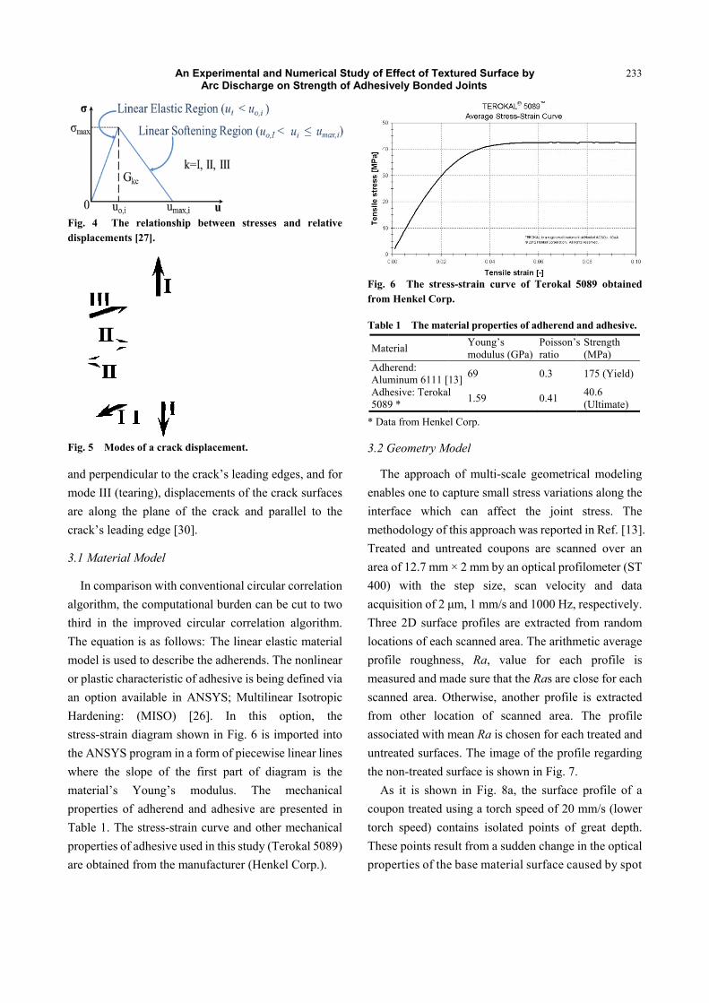
Fig. 4 Thedisplacement
Fig. 5 Mode
and perpendmode (teare along thcrack�’s lead
3.1 Material
In comparalgorithm, ththird in the The equationmodel is useor plastic chan option avHardening: stress-strain the ANSYS where the smaterial�’s properties oTable 1. Thproperties ofare obtained
An
e relationship s [27].
es of a crack di
dicular to the aring), displahe plane of ting edge [30]
l Model
rison with conhe computati
improved cn is as followed to describearacteristic ovailable in A
(MISO) [diagram shoprogram in a
slope of the Young�’s m
of adherend ae stress-strainf adhesive use
d from the ma
ExperimentaArc Discha
between stre
isplacement.
crack�’s leadinacements of ththe crack an].
nventional cironal burden circular corre
ws: The lineae the adherendf adhesive is b
ANSYS; Mul[26]. In thown in Fig. 6a form of piec
first part ofmodulus. Tand adhesive n curve and oed in this studanufacturer (H
al and Numeriarge on Stren
esses and rel
ng edges, andhe crack surf
nd parallel to
rcular correlacan be cut to lation algorit
ar elastic matds. The nonlibeing definedltilinear Isotrhis option, 6 is imported ewise linear lf diagram is
The mechanare presente
other mechandy (Terokal 50Henkel Corp.)
ical Study of gth of Adhes
ative
d for faces o the
ation two
thm. erial near d via ropic
the into
lines the nical ed in nical 089) ).
Fig.from
Tab
Ma
AdhAluAdh508
* Da
3.2
TenaintemetTrearea400acqThrlocapromeascanfromassountrthe
AcoutorcThepro
Effect of Texsively Bonded
. 6 The stresm Henkel Corp
ble 1 The mat
aterial
herend: uminum 6111 [hesive: Terokal89 * ata from Henke
Geometry M
The approachables one to caerface whichthodology of ated and unta of 12.7 mm 0) with the quisition of 2 ree 2D surfacations of eachfile roughneasured and mnned area. Om other locociated with mreated surfacnon-treated s
As it is showupon treated uch speed) coese points resuperties of the
xtured Surfacd Joints
ss-strain curvep.
terial propertieYoung�’s modulus (G
13] 69
l 1.59
el Corp.
Model
h of multi-scaapture small h can affectthis approachtreated coupo× 2 mm by anstep size, m, 1 mm/s a
ce profiles arh scanned areess, Ra, val
made sure that Otherwise, ancation of scamean Ra is ches. The imagsurface is sho
wn in Fig. 8ausing a torch ntains isolateult from a sude base materi
ce by
e of Terokal 5
es of adherend
GPa) Poisson�’sratio
0.3
0.41
ale geometricstress variatiot the joint h was reportedons are scann optical profscan velocit
and 1000 Hz, re extracted fea. The arithmlue for eachthe Ras are c
nother profileanned area. hosen for eac
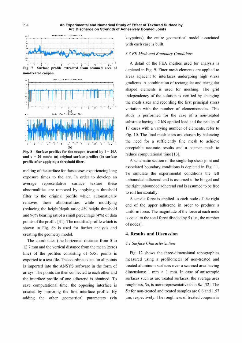
ge of the profown in Fig. 7.a, the surface
speed of 20 ed points of dden change ial surface ca
233
5089 obtained
and adhesive.s Strength
(MPa)
175 (Yield)
40.6 (Ultimate)
cal modelingons along the
stress. Thed in Ref. [13]
nned over anfilometer (STty and datarespectively.
from randommetic averageh profile isclose for eache is extracted
The profilech treated andfile regarding. e profile of amm/s (lowergreat depth.
in the opticalaused by spot
3
d
g e e ]. n T a .
m e s h d e d g
a r . l t
An Experimental and Numerical Study of Effect of Textured Surface by Arc Discharge on Strength of Adhesively Bonded Joints
234
Fig. 7 Surface profile extracted from scanned area of non-treated coupon.
(a)
(b)
Fig. 8 Surface profiles for the coupon treated by I = 20A and v = 20 mm/s: (a) original surface profile; (b) surface profile after applying a threshold filter.
melting of the surface for those cases experiencing long exposure times to the arc. In order to develop an average representative surface texture these abnormalities are removed by applying a threshold filter to the original profile which automatically removes these abnormalities while modifying (reducing the height/depth ratio; 4% height threshold and 96% bearing ratio) a small percentage (4%) of data points of the profile [31]. The modified profile which is shown in Fig. 8b is used for further analysis and creating the geometry model.
The coordinates (the horizontal distance from 0 to 12.7 mm and the vertical distance from the mean (zero) line) of the profiles consisting of 6351 points is exported to a text file. The coordinate data for all points is imported into the ANSYS software in the form of arrays. The points are then connected to each other and the interface profile of one adherend is obtained. To save computational time, the opposing interface is created by mirroring the first interface profile. By adding the other geometrical parameters (via
keypoints), the entire geometrical model associated with each case is built.
3.3 FE Mesh and Boundary Conditions
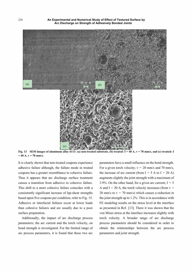
A detail of the FEA meshes used for analysis is depicted in Fig. 9. Finer mesh elements are applied to areas adjacent to interfaces undergoing high stress gradients. A combination of rectangular and triangular shaped elements is used for meshing. The grid independency of the solution is verified by changing the mesh sizes and recording the first principal stress variation with the number of elements/nodes. This study is performed for the case of a non-treated substrate having a 2 kN applied load and the results of 17 cases with a varying number of elements, refer to Fig. 10. The final mesh sizes are chosen by balancing the need for a sufficiently fine mesh to achieve acceptable accurate results and a coarser mesh to reduce computational time [13].
A schematic section of the single-lap shear joint and associated boundary conditions is depicted in Fig. 11. To simulate the experimental conditions the left unbounded adherend end is assumed to be hinged and the right unbounded adherend end is assumed to be free to roll horizontally.
A tensile force is applied to each node of the right end of the upper adherend in order to produce a uniform force. The magnitude of the force at each node is equal to the total force divided by 5 (i.e., the number of nodes).
4. Results and Discussion
4.1 Surface Characterization
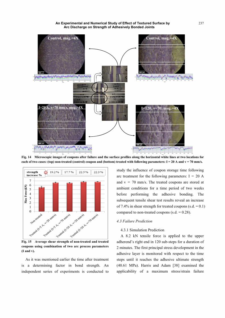
Fig. 12 shows the three-dimensional topographies measured using a profilometer of non-treated and treated aluminum surfaces over a scanned area having dimensions: 1 mm × 1 mm. In case of anisotropic surfaces such as arc treated surfaces, the average area roughness, Sa, is more representative than Ra [32]. The Sa for non-treated and treated samples are 0.6 and 1.57
m, respectively. The roughness of treated coupons is
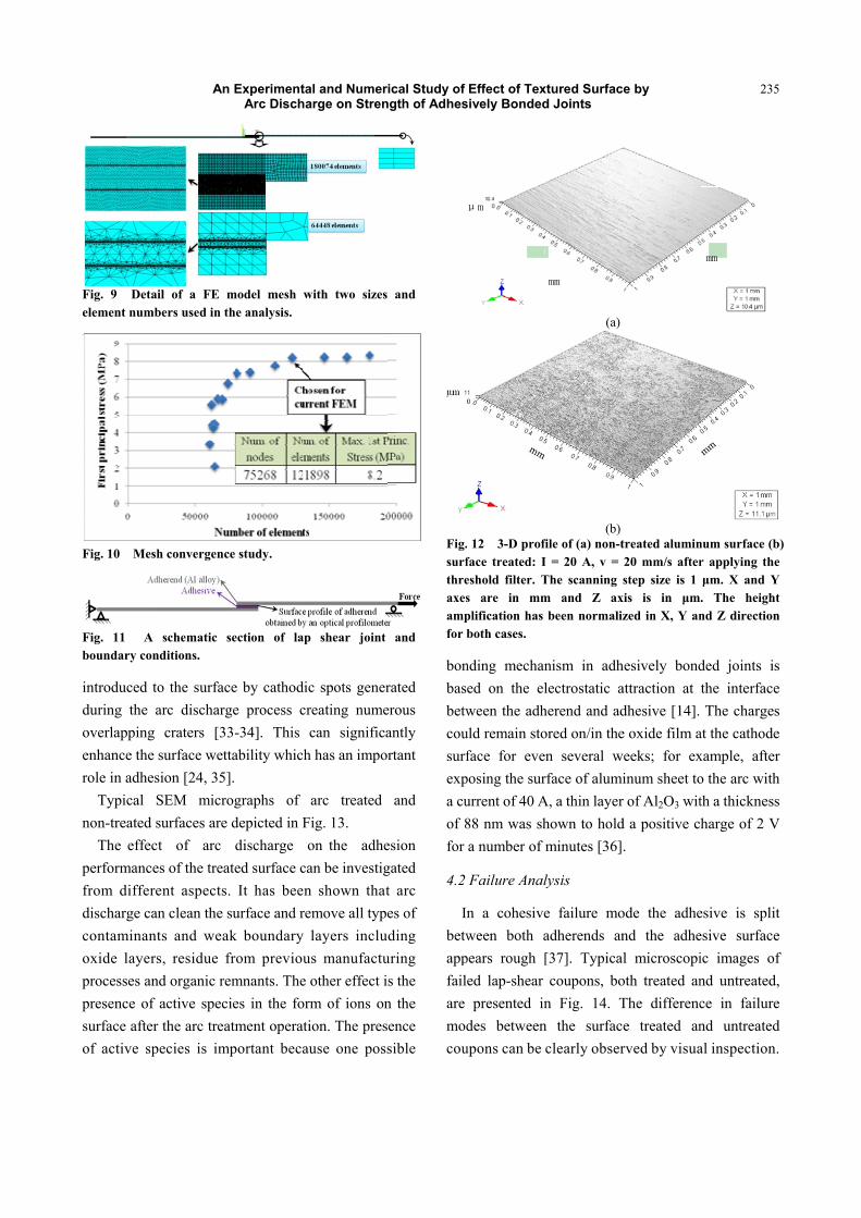
Fig. 9 Detaelement numb
Fig. 10 Mes
Fig. 11 A boundary con
introduced tduring the overlapping enhance the role in adhes
Typical non-treated
The effecperformancefrom differdischarge cacontaminanoxide layerprocesses anpresence of surface afterof active sp
An
ail of a FE mbers used in th
sh convergence
schematic senditions.
to the surfacearc discharge
craters [33surface wetta
sion [24, 35].SEM microsurfaces are d
ct of arc es of the treatent aspects.
an clean the sunts and weakrs, residue frnd organic rem
active specier the arc treatpecies is imp
ExperimentaArc Discha
model mesh whe analysis.
e study.
ection of lap
e by cathodice process cr-34]. This cability which . graphs of adepicted in Fidischarge o
ted surface caIt has been
urface and rek boundary lrom previoumnants. The oes in the formtment operatiportant becau
al and Numeriarge on Stren
with two sizes
shear joint
c spots generreating numecan significahas an impor
arc treated ig. 13. on the adhean be investign shown thatmove all typelayers includs manufactuother effect ism of ions onon. The preseuse one poss
ical Study of gth of Adhes
and
and
rated rous
antly rtant
and
esion gated t arc es of ding
uring s the n the ence sible
Fig.surfthreaxesampfor b
bonbasbetwcousurfexpa cuof 8for
4.2
Inbetwappfailare modcou
Effect of Texsively Bonded
. 12 3-D profface treated: Ieshold filter. Ts are in mmplification has both cases.
nding mechaned on the elween the adh
uld remain stoface for eve
posing the sururrent of 40 A88 nm was sha number of
Failure Anal
n a cohesiveween both a
pears rough [ed lap-shear presented in
des betweenupons can be
P�
xtured Surfacd Joints
(a)
(b) file of (a) non-tI = 20 A, v = The scanning m and Z ax
been normaliz
nism in adhlectrostatic a
herend and adored on/in theen several wrface of alumiA, a thin layerhown to holdminutes [36]
lysis
e failure moadherends an[37]. Typicacoupons, bo
n Fig. 14. Tn the surfacclearly obser
PP
ce by
treated alumin20 mm/s afterstep size is 1
xis is in mzed in X, Y an
hesively bondattraction at dhesive [14]. e oxide film a
weeks; for exinum sheet tor of Al2O3 witd a positive c.
ode the adhend the adhel microscopi
oth treated anThe difference treated anrved by visua
235
num surface (br applying the
m. X and Y. The heightnd Z direction
ded joints isthe interfaceThe charges
at the cathodexample, aftero the arc withth a thicknessharge of 2 V
esive is splitesive surfaceic images ofnd untreated,ce in failurend untreatedal inspection.
PP�
5
b) e
Y t n
s e s e r h s
V
t e f , e d .
An Experimental and Numerical Study of Effect of Textured Surface by Arc Discharge on Strength of Adhesively Bonded Joints
236
Fig. 13 SEM images of aluminum alloy 6111: (a) non-treated substrate, (b) treated: I = 40 A, v = 70 mm/s, and (c) treated: I = 40 A, v = 70 mm/s.
It is clearly shown that non-treated coupons experience adhesive failure although, the failure mode in treated coupons has a greater resemblance to cohesive failure. Thus it appears that arc discharge surface treatment causes a transition from adhesive to cohesive failure. This shift to a more cohesive failure coincides with a consistently significant increase of lap-shear strengths based upon five coupons per condition, refer to Fig. 15. Adhesive or interfacial failures occur at lower loads than cohesive failures and are usually due to a poor surface preparation.
Additionally, the impact of arc discharge process parameters; the arc current and the torch velocity, on bond strength is investigated. For the limited range of arc process parameters, it is found that these two arc
parameters have a small influence on the bond strength. For a given torch velocity; v = 20 mm/s and 70 mm/s, the increase of arc current (from I = 5 A to I = 20 A) augments slightly the joint strength with a maximum of 3.9%. On the other hand, for a given arc current; I = 5 A and I = 20 A, the torch velocity increases (from v = 20 mm/s to v = 70 mm/s) which causes a reduction in the joint strength up to 1.2%. This is in accordance with FE modeling results on the stress level at the interface as presented in Ref. [13]. There it was shown that the von Mises stress at the interface increases slightly with torch velocity. A broader range of arc discharge process parameters should be considered in order to obtain the relationships between the arc process parameters and joint strength.
����P(c)�
����P�(b)
����P(a)
An Experimental and Numerical Study of Effect of Textured Surface by Arc Discharge on Strength of Adhesively Bonded Joints
237
I=20 A, v=70 mm/s, mag.=4X I=120, v=70, mag.=4X
Control, mag.=4X Control, mag.=4X
Fig. 14 Microscopic images of coupons after failure and the surface profiles along the horizontal white lines at two locations for each of two cases: (top) non-treated (control) coupon and (bottom) treated with following parameters: I = 20 A and v = 70 mm/s.
Fig. 15 Average shear strength of non-treated and treated coupons using combination of two arc process parameters (I and v).
As it was mentioned earlier the time after treatment is a determining factor in bond strength. An independent series of experiments is conducted to
study the influence of coupon storage time following arc treatment for the following parameters: I = 20 A and v = 70 mm/s. The treated coupons are stored at ambient conditions for a time period of two weeks before performing the adhesive bonding. The subsequent tensile shear test results reveal an increase of 7.4% in shear strength for treated coupons (s.d. = 0.1) compared to non-treated coupons (s.d. = 0.28).
4.3 Failure Prediction
4.3.1 Simulation Prediction A 8.2 kN tensile force is applied to the upper
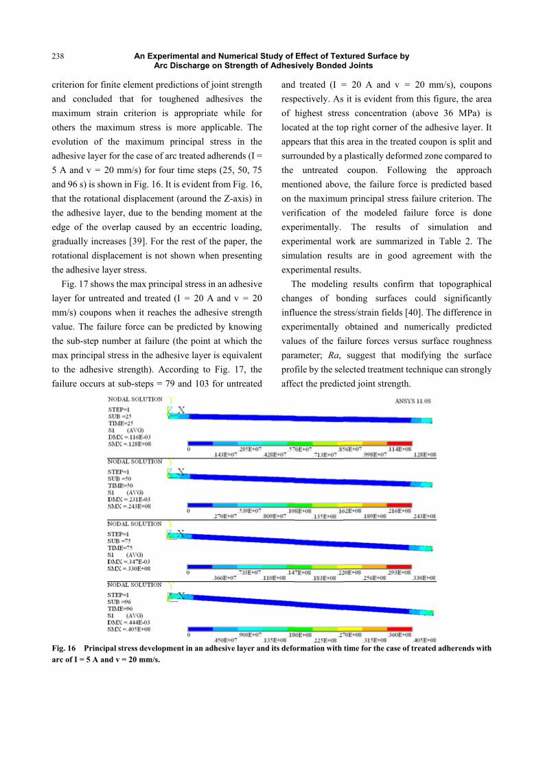
adherend�’s right end in 120 sub-steps for a duration of 2 minutes. The first principal stress development in the adhesive layer is monitored with respect to the time steps until it reaches the adhesive ultimate strength (40.61 MPa). Harris and Adam [38] examined the applicability of a maximum stress/strain failure
238
criterion for and conclumaximum sothers the mevolution oadhesive lay5 A and v =and 96 s) is sthat the rotathe adhesiveedge of the gradually inrotational dithe adhesive
Fig. 17 shlayer for unmm/s) coupvalue. The fthe sub-stepmax principto the adhefailure occur
Fig. 16 Prinarc of I = 5 A
An
finite elemenuded that fostrain criteriomaximum strof the maximyer for the cas= 20 mm/s) fshown in Fig
ational displace layer, due t
overlap cauncreases [39].isplacement ie layer stress. hows the max treated and tons when it failure force
p number at fal stress in thsive strengthrs at sub-step
ncipal stress deA and v = 20 mm
ExperimentaArc Discha
nt predictionsor toughenedon is appropress is more mum principse of arc treatefor four time . 16. It is evidcement (arouto the bendinused by an e For the rest is not shown
principal strereated (I = 2reaches the acan be predi
failure (the pohe adhesive lah). Accordingps = 79 and 1
evelopment in am/s.
al and Numeriarge on Stren
s of joint strend adhesives priate while applicable.
pal stress in ed adherendssteps (25, 50
dent from Figund the Z-axisng moment atccentric loadof the paperwhen presen
ess in an adhe20 A and v =adhesive strencted by knowoint at whichayer is equivag to Fig. 17,103 for untre
an adhesive lay
ical Study of gth of Adhes
ngth the for
The the
s (I = 0, 75 g. 16, s) in t the ding, , the
nting
esive = 20 ngth wing h the alent , the eated
andrespof locaappsurrthe menon tveriexpexpsimexp
Tchainflexpvaluparaproaffe
yer and its defo
Effect of Texsively Bonded
d treated (I =pectively. Ashighest stresated at the to
pears that thisrounded by a
untreated ntioned abovthe maximumification of
perimentally. perimental wo
mulation resuperimental resThe modelinganges of boluence the streperimentally ues of the faameter; Ra, file by the select the predic
ormation with
xtured Surfacd Joints
= 20 A and it is evident ss concentratp right corne
s area in the tplastically decoupon. F
ve, the failurem principal st
the modeledThe resul
ork are summlts are in gsults. g results cononding surfaess/strain fielobtained an
ailure forces suggest tha
lected treatmeted joint stren
time for the ca
ce by
v = 20 mmfrom this fig
tion (above er of the adhetreated coupoeformed zoneollowing the force is pretress failure cd failure folts of simumarized in Tood agreeme
nfirm that taces could lds [40]. The
nd numericalversus surfac
at modifying ent techniquength.
ase of treated a
m/s), couponsgure, the area36 MPa) is
esive layer. Iton is split ande compared tohe approachedicted basedcriterion. Theorce is doneulation and
Table 2. Theent with the
opographicalsignificantlydifference in
lly predictedce roughness
the surfacee can strongly
adherends with
s a s t d o h d e e d e e
l y n d s e y
h
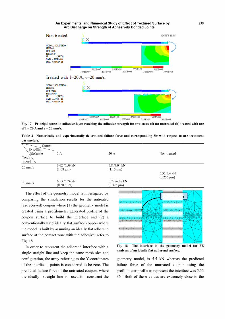
Fig. 17 Prinof I = 20 A an Table 2 Nuparameters.
Exp./Sim (Ra(µm)
Torch speed
20 mm/s
70 mm/s
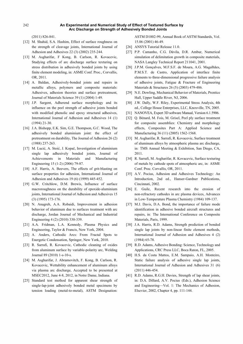
The effeccomparing (as-receivedcreated usincoupon surconventionathe model issurface at thFig. 18.
In order tsingle straigconfiguratioof the interfpredicted fathe ideally
An
ncipal stress innd v = 20 mm/s
merically and
Current m.
)) 5 A
6.6(1.0
6.5(0.3
t of the geomthe simulatio
d) coupon whng a profilomrface to buially used ideas built by assuhe contact zo
to represent tght line and kon, the array rfacial points ilure force of straight lin
ExperimentaArc Discha
n adhesive layes.
d experimental
A
2 /6.59 kN 08 µm)
3 /5.74 kN 307 µm)
metry model ion results foere (1) the ge
meter generatld the inter
ally flat surfauming an ideane with the a
the adherendkeep the samreferring to this consideredf the untreate
ne is used t
al and Numeriarge on Stren
er reaching the
lly determined
is investigatedfor the untreeometry moded profile ofrface and (2ce coupon wally flat adheradhesive, refe
d interface wime mesh size
he Y-coordind to be zero. ed coupon, wo construct
ical Study of gth of Adhes
e adhesive stre
d failure force
20 A
6.8 /7.04 k(1.15 µm)
6.79 /6.08(0.325 µm
d by eated del is f the 2) a
where rend er to
ith a and
nates The
where t the
Fig.anal
geofailuprokN.
Effect of Texsively Bonded
ength for two c
e and correspo
kN
kN m)
. 18 The inlyses of an idea
ometry modeure force ofilometer pro. Both of the
xtured Surfacd Joints
cases of: (a) un
onding Ra wit
No
5.5(0.
nterface in thally flat adhere
el, is 5.5 kNof the untreofile to represese values ar
ce by
ntreated (b) tr
th respect to
on-treated
55/5.4 kN .256 µm)
e geometry mend surface.
N whereas theated couponsent the interfre extremely
239
eated with arc
arc treatment
model for FE
he predictedn using theface was 5.55
close to the
9
c
t
E
d e 5 e
An Experimental and Numerical Study of Effect of Textured Surface by Arc Discharge on Strength of Adhesively Bonded Joints
240
experimental value of 5.4 kN. Therefore, it is feasible to draw the conclusion that for the case of the as-received aluminum alloy surface (low surface roughness) a straight line for the interface is a reasonable assumption to use in the geometry model.
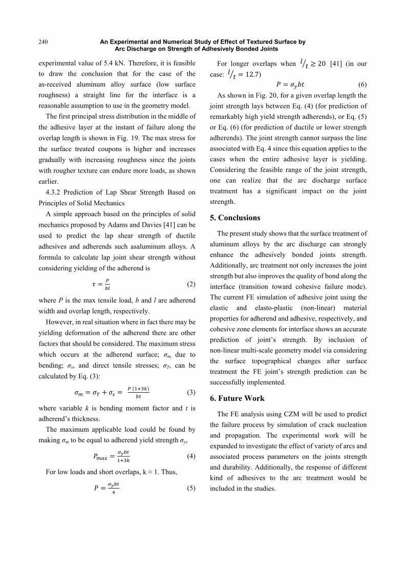
The first principal stress distribution in the middle of the adhesive layer at the instant of failure along the overlap length is shown in Fig. 19. The max stress for the surface treated coupons is higher and increases gradually with increasing roughness since the joints with rougher texture can endure more loads, as shown earlier.
4.3.2 Prediction of Lap Shear Strength Based on Principles of Solid Mechanics
A simple approach based on the principles of solid mechanics proposed by Adams and Davies [41] can be used to predict the lap shear strength of ductile adhesives and adherends such asaluminum alloys. A formula to calculate lap joint shear strength without considering yielding of the adherend is
(2)
where P is the max tensile load, b and l are adherend width and overlap length, respectively.
However, in real situation where in fact there may be yielding deformation of the adherend there are other factors that should be considered. The maximum stress which occurs at the adherend surface; m, due to bending; s, and direct tensile stresses; T, can be calculated by Eq. (3):
(3)
where variable k is bending moment factor and t is adherend�’s thickness.
The maximum applicable load could be found by making m to be equal to adherend yield strength y,
(4)
For low loads and short overlaps, k 1. Thus,
(5)
For longer overlaps when [41] (in our case: )
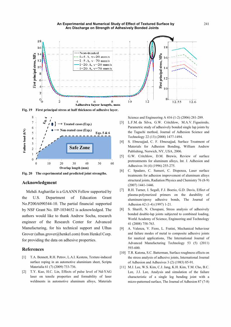
(6) As shown in Fig. 20, for a given overlap length the
joint strength lays between Eq. (4) (for prediction of remarkably high yield strength adherends), or Eq. (5) or Eq. (6) (for prediction of ductile or lower strength adherends). The joint strength cannot surpass the line associated with Eq. 4 since this equation applies to the cases when the entire adhesive layer is yielding. Considering the feasible range of the joint strength, one can realize that the arc discharge surface treatment has a significant impact on the joint strength.
5. Conclusions
The present study shows that the surface treatment of aluminum alloys by the arc discharge can strongly enhance the adhesively bonded joints strength. Additionally, arc treatment not only increases the joint strength but also improves the quality of bond along the interface (transition toward cohesive failure mode). The current FE simulation of adhesive joint using the elastic and elasto-plastic (non-linear) material properties for adherend and adhesive, respectively, and cohesive zone elements for interface shows an accurate prediction of joint�’s strength. By inclusion of non-linear multi-scale geometry model via considering the surface topographical changes after surface treatment the FE joint�’s strength prediction can be successfully implemented.
6. Future Work
The FE analysis using CZM will be used to predict the failure process by simulation of crack nucleation and propagation. The experimental work will be expanded to investigate the effect of variety of arcs and associated process parameters on the joints strength and durability. Additionally, the response of different kind of adhesives to the arc treatment would be included in the studies.
An Experimental and Numerical Study of Effect of Textured Surface by Arc Discharge on Strength of Adhesively Bonded Joints
241
Fig. 19 First principal stress at half thickness of adhesive layer.
Fig. 20 The experimental and predicted joint strengths.
Acknowledgment
Mehdi Asgharifar is a GAANN Fellow supported by the U.S. Department of Education Grant No.P200A090344-10. The partial financial supported by NSF Grant No. IIP-1034652 is acknowledged. The authors would like to thank Andrew Socha, research engineer of the Research Center for Advanced Manufacturing, for his technical support and Ulhas Grover ([email protected]) from Henkel Corp. for providing the data on adhesive properties.
References [1] T.A. Bennett, R.H. Petrov, L.A.I. Kestens, Texture-induced
surface roping in an automotive aluminium sheet, Scripta Materialia 61 (7) (2009) 733-736.
[2] T.Y. Kuo, H.C. Lin, Effects of pulse level of Nd-YAG laser on tensile properties and formability of laser weldments in automotive aluminum alloys, Materials
Science and Engineering A 416 (1-2) (2006) 281-289. [3] L.F.M. da Silva, G.W. Critchlow, M.A.V. Figueiredo,
Parametric study of adhesively bonded single lap joints by the Taguchi method, Journal of Adhesion Science and Technology 22 (13) (2008) 1477-1494.
[4] S. Ebnesajjad, C. F. Ebnesajjad, Surface Treatment of Materials for Adhesion Bonding, William Andrew Publishing, Norwich, NY, USA, 2006.
[5] G.W. Critchlow, D.M. Brewis, Review of surface pretreatments for aluminum alloys, Int. J. Adhesion and Adhesives 16 (4) (1996) 255-275.
[6] C. Spadaro, C. Sunseri, C. Dispenza, Laser surface treatments for adhesion improvement of aluminum alloys structural joints, Radiation Physics and Chemistry 76 (8-9) (2007) 1441-1446.
[7] R.H. Turner, I. Segall, F.J. Boerio, G.D. Davis, Effect of plasma-polymerized primers on the durability of aluminum/epoxy adhesive bonds, The Journal of Adhesion 62 (1-4) (1997) 1-21.
[8] S. Sharifi, N. Choupani, Stress analysis of adhesively bonded double-lap joints subjected to combined loading, World Academy of Science, Engineering and Technology 41 (2008) 758-763.
[9] A. Valenza, V. Fiore, L. Fratini, Mechanical behaviour and failure modes of metal to composite adhesive joints for nautical applications, The International Journal of Advanced Manufacturing Technology 53 (5) (2011) 593-600.
[10] T.R. Katona, S.C. Batterman, Surface roughness effects on the stress analysis of adhesive joints, International Journal of Adhesion and Adhesives 3 (2) (1983) 85-91.
[11] M.J. Lee, W.S. Kim, C.J. Jang, K.H. Kim, T.M. Cho, B.C. Lee, J.J. Lee, Analysis and simulation of the failure characteristic of a single leg bending joint with a micro-patterned surface, The Journal of Adhesion 87 (7-8)
An Experimental and Numerical Study of Effect of Textured Surface by Arc Discharge on Strength of Adhesively Bonded Joints
242
(2011) 826-841. [12] M. Shahid, S.A. Hashim, Effect of surface roughness on
the strength of cleavage joints, International Journal of Adhesion and Adhesives 22 (3) (2002) 235-244.
[13] M. Asgharifar, F Kong, B. Carlson, R. Kovacevic, Studying effects of arc discharge surface texturing on stress distribution in adhesively bonded joints by using finite element modeling, in: ASME Conf. Proc., Corvallis, OR, 2011.
[14] A. Baldan, Adhesively-bonded joints and repairs in metallic alloys, polymers and composite materials: Adhesives, adhesion theories and surface pretreatment, Journal of Materials Science 39 (1) (2004) 1-49.
[15] J.P. Sargent, Adherend surface morphology and its influence on the peel strength of adhesive joints bonded with modified phenolic and epoxy structural adhesives, International Journal of Adhesion and Adhesives 14 (1) (1994) 21-30.
[16] J.A. Bishopp, E.K. Sim, G.E. Thompson, G.C. Wood, The adhesively bonded aluminium joint: the effect of pretreatment on durability, The Journal of Adhesion 26 (2) (1988) 237-263.
[17] M. Luci , A. Stoi , J. Kopa , Investigation of aluminium single lap adhesively bonded joints, Journal of Achievements in Materials and Manufacturing Engineering 15 (1-2) (2006) 79-87.
[18] A.F. Harris, A. Beevers, The effects of grit-blasting on surface properties for adhesion, International Journal of Adhesion and Adhesives 19 (6) (1999) 445-452.
[19] G.W. Critchlow, D.M. Brewis, Influence of surface macroroughness on the durability of epoxide-aluminium joints, International Journal of Adhesion and Adhesives 15 (3) (1995) 173-176.
[20] N. Anagreh, A.A. Robaidi, Improvement in adhesion behavior of aluminum due to surfaces treatment with arc discharge, Jordan Journal of Mechanical and Industrial Engineering 4 (2) (2010) 330-339.
[21] A.A. Fridman, L.A. Kennedy, Plasma Physics and Engineering, Taylor & Francis, New York, 2004.
[22] A. Anders, Cathodic Arcs: From Fractal Spots to Energetic Condensation, Springer, New York, 2010.
[23] R. Sarrafi, R. Kovacevic, Cathodic cleaning of oxides from aluminum surface by variable-polarity arc, Welding Journal 89 (2010) 1-s-10-s.
[24] M. Asgharifar, J. Abramovitch, F. Kong, B. Carlson, R. Kovacevic, Wettability enhancement of aluminum alloys via plasma arc discharge, Accepted to be presented at MSEC2012, June 4-8, 2012, in Notre Dame, Indiana.
[25] Standard test method for apparent shear strength of single-lap-joint adhesively bonded metal specimens by tension loading (metal-to-metal), ASTM Designation:
ASTM D1002-99, Annual Book of ASTM Standards, Vol. 15.06 (2001) 46-49.
[26] ANSYS Tutorial Release 11.0. [27] P.P. Camanho, C.G. Dávila, D.R. Ambur, Numerical
simulation of delimitation growth in composite materials, NASA Langley Technical Report 211041, 2001.
[28] J.P.M. Gonçalves, M.F.S.F. de Moura, A.G. Magalhães, P.M.S.T. de Castro, Application of interface finite elements to three-dimensional progressive failure analysis of adhesive joints, Fatigue & Fracture of Engineering Materials & Structures 26 (5) (2003) 479-486.
[29] N.E. Dowling, Mechanical Behavior of Materials, Prentice Hall, Upper Saddle River, NJ, 2006.
[30] J.W. Dally, W.F. Riley, Experimental Stress Analysis, 4th ed., College House Enterprises, LLC, Knoxville, TN, 2005.
[31] NANOVEA, Expert 3D software Manual, Version 6.1.5906. [32] Q. Bénard, M. Fois, M. Grisel, Peel ply surface treatment
for composite assemblies: Chemistry and morphology effects, Composites Part A: Applied Science and Manufacturing 36 (11) (2005) 1562-1568.
[33] M. Asgharifar, R. Sarrafi, R. Kovacevic, Surface treatment of aluminum alloys by atmospheric plasma arc discharge, in: TMS Annual Meeting & Exhibition, San Diego, CA, 2011.
[34] R. Sarrafi, M. Asgharifar, R. Kovacevic, Surface texturing of metals by cathode spots of atmospheric arc, in: ASME Conf. Proc. Corvallis, OR, 2011.
[35] A.V. Pocius, Adhesion and Adhesives Technology: An Introduction, 2nd ed., Hanser-Gardner Publications, Cincinnati, 2002.
[36] E. Guile, Recent research into the erosion of non-refractory cathodes in arc plasma devices, Advances in Low-Temperature Plasma Chemistry (1984) 109-137.
[37] M.J. Davis, D.A. Bond, the importance of failure mode identification in adhesive bonded aircraft structures and repairs, in: The International Conference on Composite Materials, Paris, 1999.
[38] J.A. Harris, R.D. Adams, Strength prediction of bonded single lap joints by non-linear finite element methods, International Journal of Adhesion and Adhesives 4 (2) (1984) 65-78.
[39] R.D. Adams, Adhesive Bonding: Science, Technology and Applications, CRC Press LLC, Boca Raton, FL, 2005.
[40] H.S. da Costa Mattos, E.M. Sampaio, A.H. Monteiro, Static failure analysis of adhesive single lap joints, International Journal of Adhesion and Adhesives 31 (6) (2011) 446-454.
[41] R.D. Adams, R.G.H. Davies, Strength of lap shear joints, in: D.A. Dillard, A.V. Pocius (Eds.), Adhesion Science and Engineering�—Vol. 1: The Mechanics of Adhesion, Elsevier, 2002, Chapter 4, pp. 111-144.