Embed Size (px)
Citation preview
IEEE TRANSACTIONS ON COMMUNICATIONS, VOL. 60, NO. 10, OCTOBER 2012 2829
An Adaptive Hybrid ARQ Scheme withConstant Packet Lengths
Tien-Yu Lin, Student Member, IEEE, Shih-Kai Lee, Hung-Hua Tang, and Mao-Chao Lin, Member, IEEE
Abstract—We propose a hybrid ARQ (HARQ) scheme forwhich a rate-1/2 error-correcting code with code length equalto the packet length is used in the HARQ operation, whereeach packet comprises two subpackets of equal lengths. For theHARQ system with constant packet lengths, the utilization ofsubpackets enables the flexibility of carrying new message (ordata) in the retransmissions. Hence, such a system can gainadditional throughput as compared to the system using all-redundancy retransmissions under the conditions of moderateto high signal-to-noise ratios (SNR). In the proposed HARQscheme, each of the subpackets can be chosen as a data part,or a redundancy part, or a function of two subpackets, wherethe data part or the redundancy part may belong to differentcodewords of the rate-1/2 error-correcting code. With a properdesign of the function subpacket, we can adaptively control theerror-correcting capability used in the HARQ operation. The keyidea is that there is possibility of recovering three data subpacketsin one retransmission and hence increasing the throughput. Theprice is that in each retransmission, up to three bits are needed inthe feedback channel to indicate which subpacket is successfullyrecovered.
Index Terms—Error-correcting codes (ECC), error detectioncodes, automatic repeat request (ARQ), fading channel.
I. INTRODUCTION
HYBRID automatic repeat request (HARQ), which is amixture of forward error correction (FEC) and ARQ
[1]–[3], is an error-control technique that can achieve bothhigh transmission reliability and efficient system throughput.HARQ schemes can obtain good throughput performanceby using packet combining, for which powerful decodingcan be implemented based on the combination of erroneouspackets and the following retransmitted packets. There is asimple and effective HARQ technique called Chase combiningor diversity combining [2]. In such a system, a packet isrepeatedly transmitted, while the receiver combines multiplereceived versions of the same packet to increase the data
Paper approved by L. K. Rasmussen, the Editor for Iterative Detection De-coding and ARQ of the IEEE Communications Society. Manuscript receivedJanuary 25, 2010; revised October 18, 2010, June 21, 2011, and January 27,2012.
T.-Y. Lin is with the Graduate Institute of Communication Engineer-ing, National Taiwan University, Taipei 106, Taiwan, R.O.C. (e-mail:[email protected]).
S.-K. Lee is with the Department of Communication Engineer-ing, Yuan Ze University, Tao Yuan 32003, Taiwan, R.O.C. (e-mail:[email protected]).
H.-H. Tang is with the Department of Electrical Engineering, LunghwaUniversity of Science and Technology, Taoyuan 333, Taiwan, R.O.C. (e-mail:[email protected]).
M.-C. Lin is with the Department of Electrical Engineering, National Tai-wan University, Taipei 106, Taiwan, R.O.C. (e-mail: [email protected]).
This work was supported by the National Science Council, Taiwan, R.O.C.under Grant NSC 100-2221-E-002-121-MY3.
Digital Object Identifier 10.1109/TCOMM.2012.072412.100049A
reliability. A more efficient HARQ technique is the codecombining [4]–[11], for which the data (message) transmissionand the redundancy retransmission can be combined to formthe codeword of a long code. In particular, the amount ofredundancy used in the retransmissions can be arranged in anincremental way [7]–[11]. For this scheme, a data packet thatincludes the message bits, cyclic redundancy check (CRC)bits, and possibly some redundancy bits is sent in the firsttransmission. If a retransmission is requested, some additionalredundancy bits are selected to form a redundancy packet.The received data packet and accumulated redundancy packetsare combined to form a series of powerful FEC codes withincremental redundancy (IR) for decoding. IR HARQ canbe designed based on a family of rate-compatible puncturedconvolutional codes [7], turbo codes [8], or low-density parity-check (LDPC) codes [11].
For an IR HARQ system, the redundancy needed for en-suring a constant decoding reliability varies in the retransmis-sions. Usually, as the number of retransmissions increases, therequired redundancy decreases. To tackle the variable need ofredundancy, we may either use variable packet transmissionsor use constant packet transmissions which contain someredundancy bits and some new data bits. In this paper, weconsider the scenario of constant packet transmissions. Wemay divide each transmission packet into M subpackets whereM ≥ 2 and manipulate the subpackets based on the channelconditions. Basically, increasing M can provide more flexi-bility for adjusting the redundancy. Nevertheless, the systemcomplexity may also increase. Hence, we consider M = 2only.
We employ an analysis based on the mutual informationbetween the transmitted data bits and the decoded output bitsto estimate the successful rates of the first transmission andthe first retransmission in HARQ. We first investigate theHARQ scheme, denoted as Scheme AR (all-redundancy), forwhich all the bits in the first retransmission are redundancybits. It is seen that in the regime of moderate to high SNR,by applying the decoder of a rate-1/2 LDPC code to thereceived packets associated to the first transmission and thefirst retransmission, the rate of failure in recovering the datapacket is very small. Hence, in such SNR conditions, furtherretransmission is rarely needed. Throughput improvement ofusing rate-compatible LDPC codes in IR HARQ can onlyoccur in the low SNR conditions. In fact, there is a range ofSNR values for which the error-correcting capability accordingto all-redundancy retransmission is much more than necessary.This result verifies the need to consider the retransmissioncontaining both data bits and redundancy bits.
0090-6778/12$31.00 c© 2012 IEEE
2830 IEEE TRANSACTIONS ON COMMUNICATIONS, VOL. 60, NO. 10, OCTOBER 2012
In this paper, we propose an HARQ scheme with subpacketscheduling, where each packet is composed of two subpacketsof equal lengths. For the proposed scheme, denoted as SchemeSP, each subpacket can be a data subpacket, or a redundancysubpacket, or a function, F , of two subpackets, where thedata subpacket is the data part of a rate-1/2 FEC codewordand the redundancy subpacket is the redundancy part of arate-1/2 FEC codeword. A properly designed function Fand a proper subpacket scheduling can help to adjust theerror-correcting capability and the redundancy of the HARQsystems. Moreover, there is possibility of recovering threedata subpackets in one retransmission and hence increasingthe throughput. The price is that in each retransmission, upto three bits are needed in the feedback channel to indicatewhich subpacket is successfully recovered. Multi-bit feedbackhas been used in [12] for power adaption, in [9] for reliability-based IR HARQ, in [13] for subpacket transmission, andin [14] for WCDMA HARQ system with multiple transportblocks.
For the proposed scheme, we provide three versions withdifferent complexities, which are denoted by SP-I, SP-II andSP-III, respectively. For Scheme SP-I, the function subpacket,F , is used only in the first retransmission and there areat most two retransmissions. With the assistance of mutualinformation analysis, we can estimate the range of SNR valuesfor which Scheme SP-I can prevail in throughput efficiencyover Scheme AR. For Scheme SP-II, the constraint of atmost two retransmissions is removed. For Scheme SP-III, thefunction subpacket is used not only in the first retransmission,but also in many other retransmissions.
For Scheme SP-I, we provide throughput analysis based ona Markov chain model [15] and an equivalent channel char-acterization technique [16]. The analysis of Scheme SP-I fitswell with the simulation results in the moderate to high SNRregime. Throughput analysis for Scheme SP-II or SchemeSP-III can be implemented in a similar, but much morecomplicated way. Hence, for Scheme SP-II and Scheme SP-III, we provide only simulation results. As expected, furtherimprovement of throughput can be achieved in Scheme SP-IIand Scheme SP-III. For comparison, the simulation results ofa HARQ scheme with Chase combining, called Scheme CC,are also shown in this paper.
This paper is organized as follows. In Section II, thethroughput evaluation for Scheme AR is presented. In Sec-tion III, we propose Scheme SP-I together with its theoreticalanalysis and simulation results. Scheme SP-II and Scheme SP-III together with the associated simulation results are shownin Section IV. Concluding remarks are provided in Section V.
II. HARQ WITH ALL-REDUNDANCY RETRANSMISSIONS
In this section, we employ an analysis based on mutualinformation to evaluate the throughput of HARQ of constantpacket lengths for which the retransmissions contain redun-dancy bits only.
A. Scheme AR
Consider a HARQ scheme, denoted as Scheme AR. Atthe transmitter side, an error-detection CRC code C′
0 and a
rate-1/2 error-correcting code C′1 are needed, where C′
0 andC′
1 are (N,N − ncrc) and (2N,N) codes, respectively. Eachmessage sequence d of length N − ncrc is first encoded byC′
0 into an N -bit codeword u, which is used for the firsttransmission and is also used as the data part of C′
1 to createthe redundancy part1. Let p be the corresponding redundancypart of u. Clearly, (u, p) is a codeword of C′
1.Assume the packet length is equal to the code length of C′
0,i.e., N . In the first transmission, the transmitter sends a datapacket u to the receiver. If u can be correctly recovered fromthe received packet r(u), a positive acknowledgment (ACK)is returned to the transmitter to request the next data packet. Ifu can not be correctly recovered, a negative acknowledgment(NAK) is returned to request a retransmission. The redundancypart p is then sent as the first retransmission and the receivedvector r(p) combined with r(u) are processed by the decoderof C ′
1. If u still can not be correctly recovered, then a secondretransmission is required. There are many ways to designthe following retransmissions. We will see that by using apowerful LDPC code, the probability of needing the secondretransmission is very small for a wide SNR range.
B. Throughput Evaluation for Scheme AR
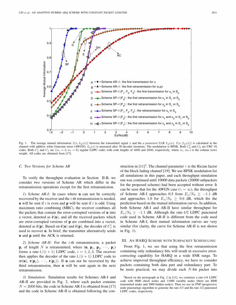
For the AWGN channel, we investigate the mutual infor-mation I(x, Lp(x)), where x and Lp(x) are, respectively, thetransmitted bit and the log-likelihood ratio (LLR) obtainedfrom the decoder output. In Fig. 1, there are two curves ofI(x, Lp(x)) for Scheme AR, where N = 2000 and C′
1 is arate-1/2 regular (3,6) LDPC code obtained from [17]. For thefirst curve, Lp(x) is obtained from the decoder output in thefirst transmission; for the second curve, Lp(x) is obtained fromthe decoder output in the first retransmission. By observingthe Es/N0 values for which the associated I(x, Lp(x)) isat least 0.9995[18]2, we can estimate that for Es/N0 ≥ 9.6dB, the first transmission will likely be successful and forEs/N0 ≥ −1.1 dB, the first retransmission will likely besuccessful. Therefore, we can estimate that the throughputwill approach (N − ncrc)/N for Es/N0 ≥ 9.6 dB and atleast (N − ncrc)/(2N) for Es/N0 ≥ −1.1 dB.
There are researches regarding the construction of rate-compatible codes of rates 1/2, 1/3, · · · , 1/(i+1), respectivelyfor applications to IR HARQ, where the first transmission tothe i-th retransmission can be combined to be a codeword ofa rate-1/(i+ 1) code. From the analysis given above, we seethat a powerful LDPC code of rate 1/2 is good enough so thatthe second retransmission is rarely needed for Es/N0 ≥ −1.1dB. The usage of a more powerful LDPC code of rate 1/3, willonly enhance the successful rate of the second retransmission,and hence can barely help in improving the throughput forEs/N0 ≥ −1.1 dB.
1In general, we may insert a high-rate channel encoder at the output ofthe CRC code to increase the the successful rate in the first transmission. Forsimplicity of presentation, we do not consider such an encoder.
2Using the formula in [18], the BER for I(x,Lp(x)) = 0.9995 can becalculated to be 1.16×10⁻⁴. For the uncoded case (first transmission) and theLDPC coded case (with retransmissions), the simulated bit error rates (BER)are about 10−4 and 10−5, respectively, while the packet error rates (PER)are about 10−1 and 10−4, respectively. To achieve PER lower than 10−2
for the uncoded case, the required mutual information and Es/N0 must belarger than 0.99997 and 9.9 dB, respectively.
LIN et al.: AN ADAPTIVE HYBRID ARQ SCHEME WITH CONSTANT PACKET LENGTHS 2831
−2 0 2 4 6 8−3 −1 1 3 5 7 9 100.3
0.4
0.5
0.6
0.7
0.8
0.9
1
Es/No(dB)
Ave
rage
Mut
ual I
nfor
mat
ion
Scheme AR−I : the first transmission for u
Scheme AR−I : the first retransmission for (u,p)
Scheme SP−I {F1, F
2, F
3} : the first transmission for u
1 in S
0
Scheme SP−I {F3} : the first retransmission for u
1 in S
1 or S
2
Scheme SP−I {F3} : the first retransmission for u
2 in S
1 or S
2
Scheme SP−I {F1, F
2, F
3} : the retransmission for u
1 in S
3
Scheme SP−I {F2} : the first retransmission for u
1 and u
2 in S
1 or S
2
Scheme SP−I {F1} : the first retransmission for u
1 and u
2 in S
1 or S
2
A
B
AC
C
D
E
F
G
H
BF
D
E
GH
Fig. 1. The average mutual information I(x,Lp(x)) between the transmitted signal x and the a posteriori LLR Lp(x). I(x,Lp(x)) is calculated in thechannel with additive white Gaussian noise (AWGN). Lp(x) is measured after 30 decoder iterations. The modulation is BPSK. Both C′
0 and C0 are CRC-16codes. Both C′
1 and C1 are (wc = 3, wr = 6) regular LDPC codes with code lengths of 4000 and 2000, respectively, where wc (wr) is the column (row)weight. All codes are obtained from [17].
C. Two Versions for Scheme AR
To verify the throughput evaluation in Section II-B, weconsider two versions of Scheme AR which differ in theretransmission operations except for the first retransmission.
1) Scheme AR-I: In cases where u can not be correctlyrecovered by the receiver and the i-th retransmission is needed,u will be sent if i is even and p will be sent if i is odd. Usingmaximum ratio combining (MRC), the receiver combines allthe packets that contain the error-corrupted versions of u intoa vector, denoted as r(u), and all the received packets whichare error-corrupted versions of p are combined into a vector,denoted as r(p). Based on r(u) and r(p), the decoder of C ′
1 isused to recover u. In brief, the transmitter alternatively sendsu and p until the ACK is returned.
2) Scheme AR-II: For the i-th retransmission, a packetpi of length N is retransmitted, where (u, p1, p2, · · · , pi)forms a rate-1/(i + 1) LDPC code, i = 1, 2, 3. The receiverthen applies the decoder of the rate-1/(i+ 1) LDPC code to(r(u), r(p1), · · · , r(pi)). If u can not be recovered by thethird retransmission, then u will be sent again in the nextretransmission.
3) Simulation: Simulation results for Schemes AR-I andAR-II are provided in Fig. 2, where each packet containsN = 2000 bits, the code in Scheme AR-I is obtained from [17]and the code in Scheme AR-II is obtained following the con-
struction in [11]3. The channel parameter γ is the Rician factorof the block fading channel [19]. We use BPSK modulation forall simulations in this paper, and each throughput simulationrun was continued until 10000 data packets (20000 subpacketsfor the proposed scheme) had been accepted without error. Itcan be seen that for the AWGN case (γ = ∞), the throughputof Scheme AR-I approaches 0.5 from Es/N0 ≥ −1.1 dBand approaches 1.0 for Es/N0 ≥ 9.6 dB, which fits theprediction based on the mutual information curves. In addition,both Scheme AR-I and AR-II have similar throughput forEs/N0 ≥ −1.1 dB. Although the rate-1/2 LDPC puncturedcode used in Scheme AR-II is different from the code usedin Scheme AR-I, their mutual information curves are verysimilar (for clarity, the curve for Scheme AR-II is not shownin Fig. 1).
III. AN HARQ SCHEME WITH SUBPACKET SCHEDULING
From Fig. 1, we see that using the first retransmissioncontaining only redundancy bits will result in excessive error-correcting capability for HARQ in a wide SNR range. Toachieve improved throughput efficiency, we have to considerpackets containing both data part and redundancy part. Tobe more practical, we may divide each N -bit packet into
3Based on the protograph in Fig. 2 in [11], we construct a rate-1/4 LDPCcode with 9000 check nodes and 11000 variable nodes (there are 8000transmitted nodes and 3000 hidden nodes). Then we use its PNP (progressivenode puncturing) algorithm to generate the rate-1/3 and the rate-1/2 puncturedLDPC codes, respectively.
2832 IEEE TRANSACTIONS ON COMMUNICATIONS, VOL. 60, NO. 10, OCTOBER 2012
0 5 10 15 20 25−3 −2 −1 1 2 3 4 6 7 8 9 11 12 13 14 16 17 18 19 21 22 23 240.2
0.3
0.4
0.5
0.6
0.7
0.8
0.9
1
Es/No (dB)
Thr
ough
put
=
=10
=0
: Scheme AR−I= =10
: Scheme CC
: Scheme SP−II using F3
: Scheme AR−II
=0
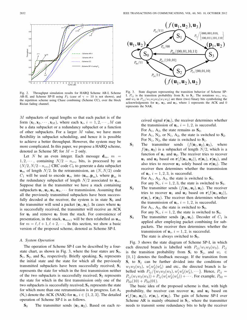
Fig. 2. Throughput simulation results for HARQ Scheme AR-I, SchemeAR-II, and Scheme SP-II using F3 (case of γ = 10 is not shown), andthe repetition scheme using Chase combining (Scheme CC), over the blockRician fading channel.
M subpackets of equal lengths so that each packet is of theform (x1, x2, · · · , xM ), where each xi, i = 1, 2, · · · ,M canbe a data subpacket or a redundancy subpacket or a functionof other subpackets. For a larger M value, we have moreflexibility in subpacket scheduling, and hence it is possibleto achieve a better throughput. However, the system may bemore complicated. In this paper, we propose a HARQ scheme,denoted as Scheme SP, for M = 2 only.
Let N be an even integer. Each message dm, m =1, 2, · · · , containing N/2 − ncrc bits, is processed by an(N/2, N/2−ncrc) CRC code C0 to generate a data subpacketum of length N/2. In the retransmission, an (N,N/2) codeC1 will be used to encode um into (um, pm), where pm isthe redundancy subpacket of length N/2 associated to um.Suppose that in the transmitter we have a stack containingsubpackets u1, u2, u3, u4, · · · for transmission. Assuming thatall the previously transmitted subpackets have been success-fully decoded at the receiver, the system is in state S0 andthe transmitter will send a packet (u1, u2). In cases where u�
is successfully received, the transmitter will receive an ACKfor u� and remove u� from the stack. For convenience ofpresentation, in the stack, um+1 will be then relabelled as um
for m = �, � + 1, �+ 2, · · · . In this section, we show a basicversion of the proposed scheme, denoted as Scheme SP-I.
A. System Operation
The operation of Scheme SP-I can be described by a four-state chart, as shown in Fig. 3, where the four states are S0,S1, S2, and S3, respectively. Briefly speaking, S0 representsthe initial state and the state for which all the previouslytransmitted subpackets have been successfully received; S1
represents the state for which in the first transmission neitherof the two subpackets is successfully received; S2 representsthe state for which in the first transmission only one of thetwo subpackets is successfully received; S3 represents the statefor which more than one retransmission is in progress. Let Ai
(Ni) denote the ACK (NAK) for ui, i ∈ {1, 2, 3}. The detailedoperation of Scheme SP-I is as follows.
S0 The transmitter sends (u1, u2). Based on each re-
0 3
1
2
00 11P 02 {10,01}P
10 111P
01 00P
20 11P
30 {00,01,10,11}P
23 {00,01,10}P
1 2( , )u u
1 2 3( , ),f u u u
1 2( , )p u
1 2 2( , ),f u u u
13
000,001,010,100,011,101,110
P
Fig. 3. State diagram representing the transition behavior of Scheme SP-I. Pij is the transition probability from Si to Sj . The notations w1, w2,and w3 in Pij/w1w2w3(w1w2) are three (two) binary bits symbolizing theacknowledgments for u1, u2, and u3, where 1 represents the ACK and 0represents the NAK.
ceived signal r(ui), the receiver determines whetherthe transmission of ui, i = 1, 2, is successful.For A1, A2, the state remains as S0.For A1, N2, or N1, A2, the state is switched to S2.For N1, N2, the state is switched to S1.
S1 The transmitter sends (f(u1, u2), u3), wheref(u1, u2) is a subpacket of length N/2, which is afunction of u1 and u2. The receiver tries to recoveru1 and u2 based on r(f(u1, u2)), r(u1), r(u2), andalso tries to recover u3 solely based on r(u3). Thereceiver then determines whether the transmissionof ui, i = 1, 2, 3, is successful.For A1, A2, A3, the state is switched to S0.For any Ni, i = 1, 2, 3, the state is switched to S3.
S2 The transmitter sends (f(u1, u2), u2). The receivertries to recover u1 and u2 based on r(f(u1, u2)),r(u1), r(u2). The receiver then determines whetherthe transmission of ui, i = 1, 2, is successful.For A1, A2, the state is switched to S0.For any Ni, i = 1, 2, the state is switched to S3.
S3 The transmitter sends (p1, u2). Decoder of C1 isapplied after employing packet combining for sub-packets. The receiver then determines whether thetransmission of ui, i = 1, 2, is successful.The state is always switched to S0.
Fig. 3 shows the state diagram of Scheme SP-I, in whicheach directed branch is labelled with Pij/w1w2(w3). Pij
is the transition probability from Si to Sj , and wi ∈{0, 1} denotes the feedback message. If the transition fromSi to Sj can be further divided into the conditions ofw1w2(w3), w′
1w′2(w
′3) and etc., the directed branch is la-
belled with Pij/{w1w2(w3), w′1w
′2(w
′3), · · · }. Hence, Pij =
Pij(w1w2(w3)) +Pij(w′1w
′2(w
′3)) + · · · . For example, P02 =
P02(10) + P02(01).The basic idea of the proposed scheme is that, with high
probability, the receiver can recover u1 and u2 based onr(f(u1, u2)), r(u1), r(u2). The gain of Scheme SP-I overScheme AR is mainly obtained in S1, where the transmitterneeds to transmit some redundancy bits to help the receiver
LIN et al.: AN ADAPTIVE HYBRID ARQ SCHEME WITH CONSTANT PACKET LENGTHS 2833
to recover u1 and u2, both of which failed in the previoustransmission. For the conditions of moderate to high SNR, inS1, only N/2 bits need to be transmitted for recovering bothu1 and u2, and in the mean time a new data subpacket u3 isalso transmitted. Since our HARQ system transmits packetswith fixed length of N bits, we can transmit an additionalsubpacket u3 in S1, which is the major factor for improvingthe throughput.
In S2, the transmitter also needs to transmit some redun-dancy bits to help the receiver to recover u1, which failed inthe previous transmission; meanwhile, a new data subpacketu2 is transmitted. In our scheduling, N/2 bits are transmittedfor recovering u1, and furthermore enhancing the probabil-ity of successful reception of u2. Accordingly, we transmit(f(u1, u2), u2) rather than (p1, u2), because for the formerthere is additional protection for the new data subpacket u2
and for the latter the additional protection does not exist.Let B be a virtual buffer that contains those data sub-
packets which have been transmitted, but not accepted by thereceiver. Possible buffer conditions in S3 will be B = {u1},B = {u1, u2}, and B = {u1, u2, u3}. For simplicity, in S3,f(u1, u2) is not employed in the transmission. In addition,possible r(f(u1, u2)) and r(u3) received in the earlier trans-mission are not used for decoding either. When the state isswitched from S3 to S0, for simplicity, B is set to ∅, i.e.,the empty set, and the associated packets in the receiverare discarded even though there may exist ui which is notsuccessfully decoded yet. Apparently, more delicate procedurecan be arranged to increase the throughput efficiency.
B. Designs for f(u1, u2)
We provide three designs for f(u1, u2), denoted by F1, F2,and F3, respectively. Comparisons for the three designs willbe made based on the throughput efficiency.F1 Consider f(u1, u2) = p−, where ((u1, u2), p−) is a
codeword of a rate-2/3 code C′1− with length 3
2N .C′
1− is obtained by puncturing C′
1 used in SchemeAR-I.
F2 Consider f(u1, u2) = (p−1 , p−
2 ), where (ui, p−i ), i =
1, 2, is a codeword of a rate-2/3 code C−1 with length
34N . In this paper, C−
1 is obtained by punctuating C1.F3 Consider f(u1, u2) = p1
⊕u2, where (u1, p1) is a
codeword of C1.Denote the decoding of Fi for Scheme SP-I by DEC-Fi.
The operation of DEC-F1 involves the decoders of C′1− and
C1. The operation of DEC-F2 involves the decoders of C−1
and C1. The operation of DEC-F3 involves the decoder of C1
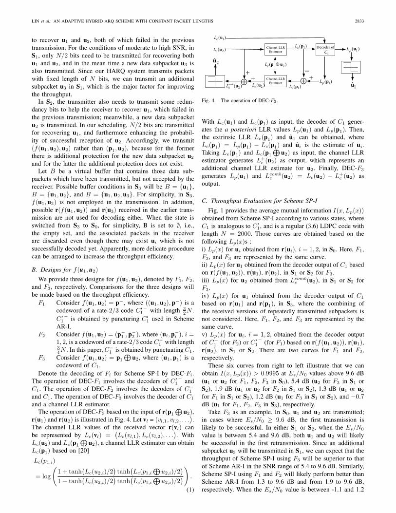
and a channel LLR estimator.The operation of DEC-F3 based on the input of r(p1
⊕u2),
r(u1) and r(u2) is illustrated in Fig. 4. Let vl = (vl,1, vl,2, . . .).
The channel LLR values of the received vector r(vl) canbe represented by Lc(vl) =
(Lc(vl,1), Lc(vl,2), . . .
). With
Lc(u2) and Lc(p1
⊕u2), a channel LLR estimator can obtain
Lc(p1) based on [20]
Lc(p1,i)
= log
(1 + tanh
(Lc(u2,i)/2
)tanh
(Lc(p1,i
⊕u2,i)/2
)1− tanh
(Lc(u2,i)/2
)tanh
(Lc(p1,i
⊕u2,i)/2
)) .
(1)
2( )cL u
2( )combcL u
Channel-LLREstimator
1 2( )cL p u
Channel-LLREstimator
1( )cL p1( )cL u
1( )pL p1( )eL p2( )cL u
2u
1u
1( )pL u1C
Decoder of
Fig. 4. The operation of DEC-F3.
With Lc(u1) and Lc(p1) as input, the decoder of C1 gener-ates the a posteriori LLR values Lp(u1) and Lp(p1). Then,the extrinsic LLR Le(p1) and u1 can be obtained, whereLe(p1) = Lp(p1) − Lc(p1) and ui is the estimate of ui.Taking Le(p1) and Lc(p1
⊕u2) as input, the channel LLR
estimator generates L+c (u2) as output, which represents an
additional channel LLR estimate for u2. Finally, DEC-F3
generates Lp(u1) and Lcombc (u2) = Lc(u2) + L+
c (u2) asoutput.
C. Throughput Evaluation for Scheme SP-I
Fig. 1 provides the average mutual information I(x, Lp(x))obtained from Scheme SP-I according to various states, whereC1 is analogous to C′
1, and is a regular (3,6) LDPC code withlength N = 2000. Those curves are obtained based on thefollowing Lp(x)s :i) Lp(x) for ui obtained from r(ui), i = 1, 2, in S0. Here, F1,F2, and F3 are represented by the same curve.ii) Lp(x) for u1 obtained from the decoder output of C1 basedon r(f(u1, u2)), r(u1), r(u2), in S1 or S2 for F3.iii) Lp(x) for u2 obtained from Lcomb
c (u2), in S1 or S2 forF3.iv) Lp(x) for u1 obtained from the decoder output of C1
based on r(u1) and r(p1), in S3, where the combining ofthe received versions of repeatedly transmitted subpackets isnot considered. Here, F1, F2, and F3 are represented by thesame curve.v) Lp(x) for ui, i = 1, 2, obtained from the decoder outputof C−
1 (for F2) or C′1− (for F1) based on r(f(u1, u2)), r(u1),
r(u2), in S1 or S2. There are two curves for F1 and F2,respectively.
These six curves from right to left illustrate that we canobtain I(x, Lp(x)) > 0.9995 at Es/N0 values above 9.6 dB(u1 or u2 for F1, F2, F3 in S0), 5.4 dB (u2 for F3 in S1 orS2), 1.9 dB (u1 or u2 for F2 in S1 or S2), 1.3 dB (u1 or u2
for F1 in S1 or S2), 1.2 dB (u1 for F3 in S1 or S2), and −0.7dB (u1 for F1, F2, F3 in S3), respectively.
Take F3 as an example. In S0, u1 and u2 are transmitted;in cases where Es/N0 ≥ 9.6 dB, the first transmission islikely to be successful. In either S1 or S2, when the Es/N0
value is between 5.4 and 9.6 dB, both u1 and u2 will likelybe successful in the first retransmission. Since an additionalsubpacket u3 will be transmitted in S1, we can expect that thethroughput of Scheme SP-I using F3 will be superior to thatof Scheme AR-I in the SNR range of 5.4 to 9.6 dB. Similarly,Scheme SP-I using F1 and F2 will likely perform better thanScheme AR-I from 1.3 to 9.6 dB and from 1.9 to 9.6 dB,respectively. When the Es/N0 value is between -1.1 and 1.2
2834 IEEE TRANSACTIONS ON COMMUNICATIONS, VOL. 60, NO. 10, OCTOBER 2012
dB, the first retransmission in Scheme AR-I is likely to besuccessful, while for Scheme SP-I using any decoder of F1,F2, and F3, it is likely to fail. Thus Scheme SP-I will beinferior to Scheme AR-I for Es/N0 values ranging from -1.1to 1.2 dB.
According to the curves for the first retransmission, we canpredict that F1 and F2 will result in very close throughputefficiency, and both will achieve better performance than F3
when the Es/N0 value is between 1.9 and 5.4 dB. Becausein that SNR regime, for F1 and F2 it is highly probablethat u1 and u2 can be recovered by the retransmission off(u1, u2), while for F3 it is very probable that only u1 couldbe recovered. However, in SNR of -1.1 to 0.3 dB, F3 mayachieve better throughput than F1 and F2, since the two mutualinformation curves for F3, respectively representing u1 and u2,are both above the curves for F1 and F2.
D. Throughput Analysis for Scheme SP-I and SimulationResults
1) Throughput Analysis: Define the throughput (efficiency)η as the average number of information bits successfullyreceived per transmitted symbol. Let λ be the average numberof successfully received data subpackets per transmission. Thethroughput of the proposed scheme can be evaluated using
η =λ
2
N2 − ncrc
N2
. (2)
In Fig. 3, with each Pij > 0, the state diagram is anirreducible ergodic Markov chain [15], and the steady stateprobability πj for each state can be obtained by solving
[π0 π1 π2 π3] = [π0 π1 π2 π3]
⎛⎜⎜⎝P00 P01 P02 0P10 0 0 P13
P20 0 0 P23
P30 0 0 0
⎞⎟⎟⎠ ,
(3)
subject to∑3
j=0 πj = 1. For P13, P23, and P30, we furtherdefine Pij,lA as the probability of transition from Si to Sj
and there are lA subpackets with ACK. For example, P13,2 =P13(011) + P13(101) + P13(110). Then, we have
λ =π0(2P00 + P02) + π1(3P10 + 2P13,2 + P13,1)
+ π2(2P20 + P23,1) + π3(2P30,2 + P30,1).(4)
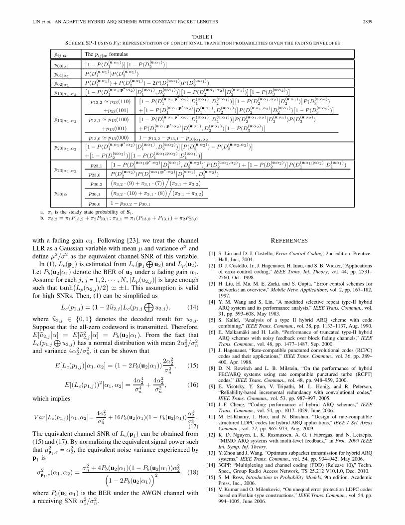
Techniques for obtaining the formulas Pij,lA and Pij are givenin Appendix A-1 and the resultant formulas for F3 are pro-vided in Table I. The formulas for F1 and F2 can be obtainedsimilarly with slight modifications. Appendix A-2 shows atechnique of simplifying all the formulas of conditional orjoint error events in Table I. Then, in Appendix A-3, we applyrandom coding bound to those simplified formulas to obtainthe numerical estimation of all the transition probabilities,steady state probabilities, and throughput efficiency. Note thatmany assumptions shown in the Appendices are valid only athigh SNRs. Hence, the obtained numerical results are expectedto fit the simulation results only at sufficiently high SNRs.
−2 0 2 4 6 8 10 12−3 −1 1 3 5 7 9 11 130
0.1
0.2
0.3
0.4
0.5
0.6
0.7
0.8
0.9
1
Es/No (dB)
Thr
ough
put
F1
F2
F3
F1
F2
F3
Simulation results
Numerical results
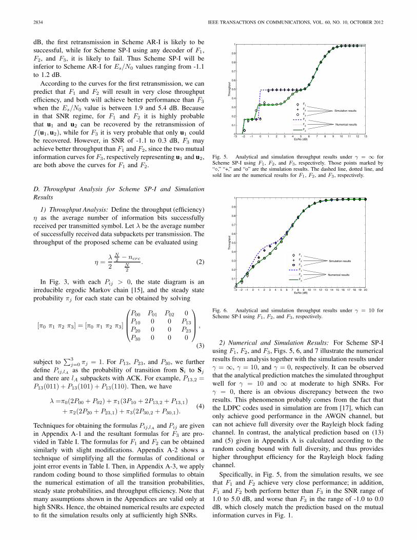
Fig. 5. Analytical and simulation throughput results under γ = ∞ forScheme SP-I using F1, F2, and F3, respectively. Those points marked by“�,” “+,” and “o” are the simulation results. The dashed line, dotted line, andsold line are the numerical results for F1, F2, and F3, respectively.
−2 0 2 4 6 8 10 12 14 16 18 20−3 −1 1 3 5 7 9 11 13 15 17 190
0.1
0.2
0.3
0.4
0.5
0.6
0.7
0.8
0.9
1
Es/No (dB)
Thr
ough
put
F1
F2
F3
F1
F2
F3
Simulation results
Numerical results
Fig. 6. Analytical and simulation throughput results under γ = 10 forScheme SP-I using F1, F2, and F3, respectively.
2) Numerical and Simulation Results: For Scheme SP-Iusing F1, F2, and F3, Figs. 5, 6, and 7 illustrate the numericalresults from analysis together with the simulation results underγ = ∞, γ = 10, and γ = 0, respectively. It can be observedthat the analytical prediction matches the simulated throughputwell for γ = 10 and ∞ at moderate to high SNRs. Forγ = 0, there is an obvious discrepancy between the tworesults. This phenomenon probably comes from the fact thatthe LDPC codes used in simulation are from [17], which canonly achieve good performance in the AWGN channel, butcan not achieve full diversity over the Rayleigh block fadingchannel. In contrast, the analytical prediction based on (13)and (5) given in Appendix A is calculated according to therandom coding bound with full diversity, and thus provideshigher throughput efficiency for the Rayleigh block fadingchannel.
Specifically, in Fig. 5, from the simulation results, we seethat F1 and F2 achieve very close performance; in addition,F1 and F2 both perform better than F3 in the SNR range of1.0 to 5.0 dB, and worse than F3 in the range of -1.0 to 0.0dB, which closely match the prediction based on the mutualinformation curves in Fig. 1.
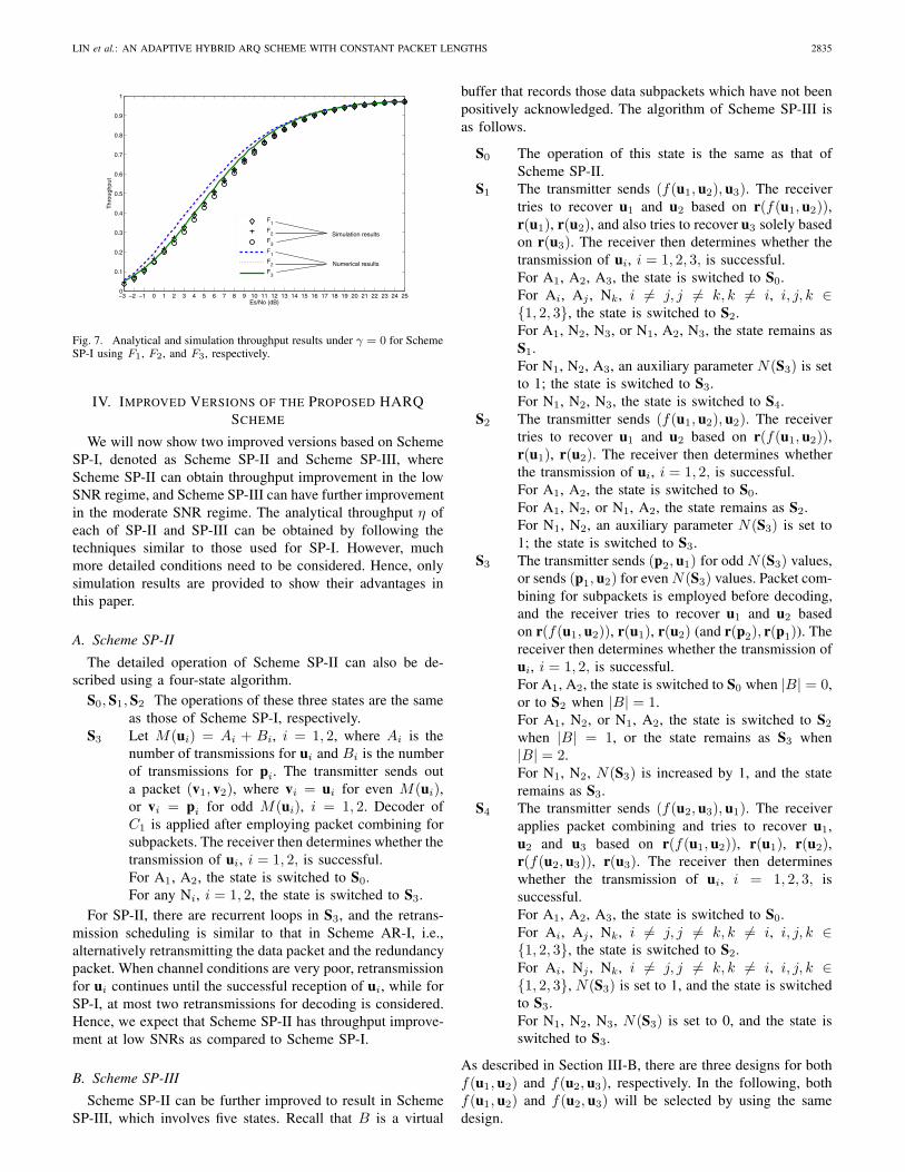
LIN et al.: AN ADAPTIVE HYBRID ARQ SCHEME WITH CONSTANT PACKET LENGTHS 2835
0 5 10 15 20 25−3 −2 −1 1 2 3 4 6 7 8 9 11 12 13 14 16 17 18 19 21 22 23 240
0.1
0.2
0.3
0.4
0.5
0.6
0.7
0.8
0.9
1
Es/No (dB)
Thr
ough
put
F1
F2
F3
F1
F2
F3
Simulation results
Numerical results
Fig. 7. Analytical and simulation throughput results under γ = 0 for SchemeSP-I using F1, F2, and F3, respectively.
IV. IMPROVED VERSIONS OF THE PROPOSED HARQSCHEME
We will now show two improved versions based on SchemeSP-I, denoted as Scheme SP-II and Scheme SP-III, whereScheme SP-II can obtain throughput improvement in the lowSNR regime, and Scheme SP-III can have further improvementin the moderate SNR regime. The analytical throughput η ofeach of SP-II and SP-III can be obtained by following thetechniques similar to those used for SP-I. However, muchmore detailed conditions need to be considered. Hence, onlysimulation results are provided to show their advantages inthis paper.
A. Scheme SP-II
The detailed operation of Scheme SP-II can also be de-scribed using a four-state algorithm.
S0, S1, S2 The operations of these three states are the sameas those of Scheme SP-I, respectively.
S3 Let M(ui) = Ai + Bi, i = 1, 2, where Ai is thenumber of transmissions for ui and Bi is the numberof transmissions for pi. The transmitter sends outa packet (v1, v2), where vi = ui for even M(ui),or vi = pi for odd M(ui), i = 1, 2. Decoder ofC1 is applied after employing packet combining forsubpackets. The receiver then determines whether thetransmission of ui, i = 1, 2, is successful.For A1, A2, the state is switched to S0.For any Ni, i = 1, 2, the state is switched to S3.
For SP-II, there are recurrent loops in S3, and the retrans-mission scheduling is similar to that in Scheme AR-I, i.e.,alternatively retransmitting the data packet and the redundancypacket. When channel conditions are very poor, retransmissionfor ui continues until the successful reception of ui, while forSP-I, at most two retransmissions for decoding is considered.Hence, we expect that Scheme SP-II has throughput improve-ment at low SNRs as compared to Scheme SP-I.
B. Scheme SP-III
Scheme SP-II can be further improved to result in SchemeSP-III, which involves five states. Recall that B is a virtual
buffer that records those data subpackets which have not beenpositively acknowledged. The algorithm of Scheme SP-III isas follows.
S0 The operation of this state is the same as that ofScheme SP-II.
S1 The transmitter sends (f(u1, u2), u3). The receivertries to recover u1 and u2 based on r(f(u1, u2)),r(u1), r(u2), and also tries to recover u3 solely basedon r(u3). The receiver then determines whether thetransmission of ui, i = 1, 2, 3, is successful.For A1, A2, A3, the state is switched to S0.For Ai, Aj , Nk, i �= j, j �= k, k �= i, i, j, k ∈{1, 2, 3}, the state is switched to S2.For A1, N2, N3, or N1, A2, N3, the state remains asS1.For N1, N2, A3, an auxiliary parameter N(S3) is setto 1; the state is switched to S3.For N1, N2, N3, the state is switched to S4.
S2 The transmitter sends (f(u1, u2), u2). The receivertries to recover u1 and u2 based on r(f(u1, u2)),r(u1), r(u2). The receiver then determines whetherthe transmission of ui, i = 1, 2, is successful.For A1, A2, the state is switched to S0.For A1, N2, or N1, A2, the state remains as S2.For N1, N2, an auxiliary parameter N(S3) is set to1; the state is switched to S3.
S3 The transmitter sends (p2, u1) for odd N(S3) values,or sends (p1, u2) for even N(S3) values. Packet com-bining for subpackets is employed before decoding,and the receiver tries to recover u1 and u2 basedon r(f(u1, u2)), r(u1), r(u2) (and r(p2), r(p1)). Thereceiver then determines whether the transmission ofui, i = 1, 2, is successful.For A1, A2, the state is switched to S0 when |B| = 0,or to S2 when |B| = 1.For A1, N2, or N1, A2, the state is switched to S2
when |B| = 1, or the state remains as S3 when|B| = 2.For N1, N2, N(S3) is increased by 1, and the stateremains as S3.
S4 The transmitter sends (f(u2, u3), u1). The receiverapplies packet combining and tries to recover u1,u2 and u3 based on r(f(u1, u2)), r(u1), r(u2),r(f(u2, u3)), r(u3). The receiver then determineswhether the transmission of ui, i = 1, 2, 3, issuccessful.For A1, A2, A3, the state is switched to S0.For Ai, Aj , Nk, i �= j, j �= k, k �= i, i, j, k ∈{1, 2, 3}, the state is switched to S2.For Ai, Nj , Nk, i �= j, j �= k, k �= i, i, j, k ∈{1, 2, 3}, N(S3) is set to 1, and the state is switchedto S3.For N1, N2, N3, N(S3) is set to 0, and the state isswitched to S3.
As described in Section III-B, there are three designs for bothf(u1, u2) and f(u2, u3), respectively. In the following, bothf(u1, u2) and f(u2, u3) will be selected by using the samedesign.
2836 IEEE TRANSACTIONS ON COMMUNICATIONS, VOL. 60, NO. 10, OCTOBER 2012
The following features of Scheme SP-III will contribute tothe throughput improvement over Scheme SP-II. First, therecurrent loops increase the frequency of using f(u1, u2).Second, in S3, the receiver exploits r(f(u1, u2)) for decoding,while such an arrangement is not used in both SP-I and SP-II. Third, in the additional state S4, the usage of f(u2, u3)provides the opportunity of simultaneously recovering threesubpackets which were not recovered in S1.
Further increase of the system throughput may be obtainedby delicately arranging more states and recurrent loops ac-cording to the feedback messages. However, such a systemwill be very complicated.
C. Simulation Results
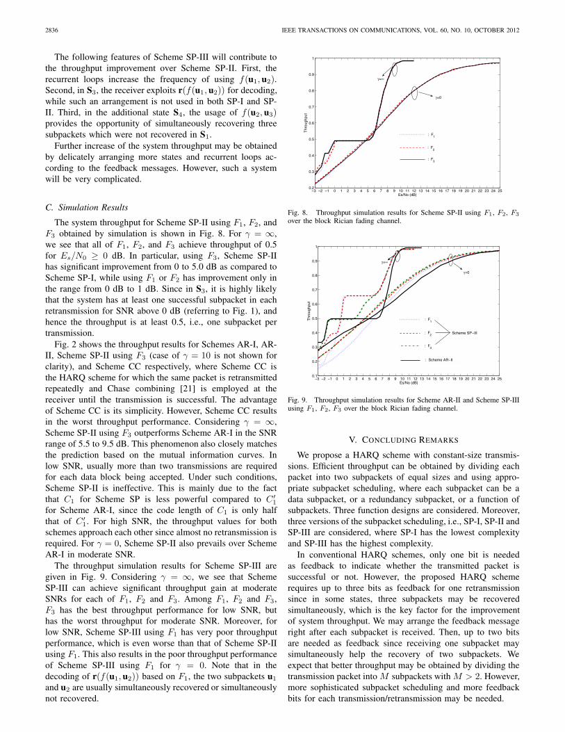
The system throughput for Scheme SP-II using F1, F2, andF3 obtained by simulation is shown in Fig. 8. For γ = ∞,we see that all of F1, F2, and F3 achieve throughput of 0.5for Es/N0 ≥ 0 dB. In particular, using F3, Scheme SP-IIhas significant improvement from 0 to 5.0 dB as compared toScheme SP-I, while using F1 or F2 has improvement only inthe range from 0 dB to 1 dB. Since in S3, it is highly likelythat the system has at least one successful subpacket in eachretransmission for SNR above 0 dB (referring to Fig. 1), andhence the throughput is at least 0.5, i.e., one subpacket pertransmission.
Fig. 2 shows the throughput results for Schemes AR-I, AR-II, Scheme SP-II using F3 (case of γ = 10 is not shown forclarity), and Scheme CC respectively, where Scheme CC isthe HARQ scheme for which the same packet is retransmittedrepeatedly and Chase combining [21] is employed at thereceiver until the transmission is successful. The advantageof Scheme CC is its simplicity. However, Scheme CC resultsin the worst throughput performance. Considering γ = ∞,Scheme SP-II using F3 outperforms Scheme AR-I in the SNRrange of 5.5 to 9.5 dB. This phenomenon also closely matchesthe prediction based on the mutual information curves. Inlow SNR, usually more than two transmissions are requiredfor each data block being accepted. Under such conditions,Scheme SP-II is ineffective. This is mainly due to the factthat C1 for Scheme SP is less powerful compared to C′
1
for Scheme AR-I, since the code length of C1 is only halfthat of C′
1. For high SNR, the throughput values for bothschemes approach each other since almost no retransmission isrequired. For γ = 0, Scheme SP-II also prevails over SchemeAR-I in moderate SNR.
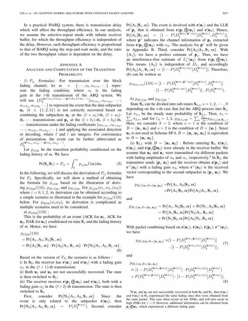
The throughput simulation results for Scheme SP-III aregiven in Fig. 9. Considering γ = ∞, we see that SchemeSP-III can achieve significant throughput gain at moderateSNRs for each of F1, F2 and F3. Among F1, F2 and F3,F3 has the best throughput performance for low SNR, buthas the worst throughput for moderate SNR. Moreover, forlow SNR, Scheme SP-III using F1 has very poor throughputperformance, which is even worse than that of Scheme SP-IIusing F1. This also results in the poor throughput performanceof Scheme SP-III using F1 for γ = 0. Note that in thedecoding of r(f(u1, u2)) based on F1, the two subpackets u1
and u2 are usually simultaneously recovered or simultaneouslynot recovered.
0 5 10 15 20 251 2 3 4−3 −2 −1 6 7 8 9 11 12 13 14 16 17 18 19 21 22 23 240.2
0.3
0.4
0.5
0.6
0.7
0.8
0.9
1
Es/No (dB)
Thr
ough
put
=
=0
: F1
: F2
: F3
Fig. 8. Throughput simulation results for Scheme SP-II using F1, F2, F3
over the block Rician fading channel.
0 5 10 15 20 25−2 2 −3 −1 1 3 4 6 7 8 9 11 12 13 14 16 17 18 19 21 22 23 240.1
0.2
0.3
0.4
0.5
0.6
0.7
0.8
0.9
1
Es/No (dB)
Thr
ough
put
=
=0
: F1
: F3
: F2 Scheme SP−III
: Scheme AR−II
Fig. 9. Throughput simulation results for Scheme AR-II and Scheme SP-IIIusing F1, F2, F3 over the block Rician fading channel.
V. CONCLUDING REMARKS
We propose a HARQ scheme with constant-size transmis-sions. Efficient throughput can be obtained by dividing eachpacket into two subpackets of equal sizes and using appro-priate subpacket scheduling, where each subpacket can be adata subpacket, or a redundancy subpacket, or a function ofsubpackets. Three function designs are considered. Moreover,three versions of the subpacket scheduling, i.e., SP-I, SP-II andSP-III are considered, where SP-I has the lowest complexityand SP-III has the highest complexity.
In conventional HARQ schemes, only one bit is neededas feedback to indicate whether the transmitted packet issuccessful or not. However, the proposed HARQ schemerequires up to three bits as feedback for one retransmissionsince in some states, three subpackets may be recoveredsimultaneously, which is the key factor for the improvementof system throughput. We may arrange the feedback messageright after each subpacket is received. Then, up to two bitsare needed as feedback since receiving one subpacket maysimultaneously help the recovery of two subpackets. Weexpect that better throughput may be obtained by dividing thetransmission packet into M subpackets with M > 2. However,more sophisticated subpacket scheduling and more feedbackbits for each transmission/retransmission may be needed.
LIN et al.: AN ADAPTIVE HYBRID ARQ SCHEME WITH CONSTANT PACKET LENGTHS 2837
In a practical HARQ system, there is transmission delaywhich will affect the throughput efficiency. In our analysis,we assume the selective-repeat mode with infinite receiverbuffer, for which the throughput efficiency is independent ofthe delay. However, such throughput efficiency is proportionalto that of HARQ using the stop-and-wait mode, and the ratioof the two throughput values is dependent on the delay.
APPENDIX AANALYSIS AND COMPUTATION OF THE TRANSITION
PROBABILITY
1) Pij Formulas: For transmission over the blockfading channel, let α = {· · · , αl, αl+1, · · · } repre-sent the fading condition, where αl is the fadinggain in the l-th transmission of the ARQ system. Wewill use {D(u:�+a1,�+a2,··· ;p:l+b1,l+b2,··· )
k
∣∣α�+a1 , α�+a2 , · · · ;αl+b1 , αl+b2 · · · } to represent the event that the data subpacketuk (k ∈ {1, 2, 3}) is not correctly recovered based oncombining the subpackets uk at the (� + a1)-th, (� + a2)-th, · · · transmissions and pk at the (l + b1)-th, (l + b2)-th,· · · transmissions under the fading coefficients {α�+a1 , α�+a2 ,· · · ; αl+b1 , αl+b2 , · · · } and applying the associated detectionor decoding, where � and l are integers. For convenienceof presentation, the event can be further abbreviated asD
(u:αa1 ,αa2 ,··· ;p:αb1,αb2
,··· )k .Let pij|α be the transition probability conditioned on the
fading history of α. We have
Pr(Sj |Si) = Pij =
∫ ∞
0
pij|αf(α)dα. (5)
In the following, we will discuss the derivation of Pij formulasfor F3. Specifically, we will show a method of obtainingthe formula for pij|α based on the illustration of deriv-ing p13|α(110), p30,1|α, and p30,2|α. For pij|α(w1, w2, (w3))where i = 0, 1, 2, its derivation can be obtained according toa simple scenario as illustrated in the example for p13|α(110)below. For p30|α(w1w2), its derivation is complicated asmultiple scenarios need to be considered.
a) p13|α(110) :This is the probability of an event {ACK for u1, ACK for
u2, NAK for u3} conditioned on state S1 and the fading historyof α. Hence, we have
p13|α(110)= Pr{A1,A2,N3
∣∣S1,α}= Pr{A1
∣∣S1,α} · Pr{A2
∣∣A1, S1,α} · Pr{N3
∣∣A1,A2, S1,α}.(6)
Based on the version of F3, the scenario is as follows :i) In S0, the receiver has r(u1) and r(u2) with a fading gainα1 in the (�+ 1)-th transmission;ii) Both u1 and u2 are not successfully recovered. The stateis then switched to S1;iii) The receiver receives r(p1
⊕u2) and r(u3), both with a
fading gain α2 in the (�+2)-th transmission. The state is thenswitched to S3.
First, consider Pr{N3
∣∣A1,A2, S1,α}. Since theevent is only related to the subpacket r(u3), thenPr{N3
∣∣A1,A2, S1,α} = P (D(u:α2)3 ). Second, consider
Pr{A1
∣∣S1,α}. The event is involved with r(u1) and the LLRof p1 that is obtained from r(p1
⊕u2) and r(u2). Hence,
Pr{A1
∣∣S1,α} = [1 − P (D(u:α1;p∗:α2)1
∣∣D(u:α1)1 , D
(u:α1)2 )],
where p∗ indicates the channel information of p1 extractedfrom r(p1
⊕u2) with α2. The analysis for p∗ will be given
in Appendix B. Third, consider Pr{A2
∣∣A1, S1,α}. With{A1}, we have a perfect estimate of p1. Thus, we havean interference-free estimate of L+
c (u2) from r(p1
⊕u2).
This means {A2} is independent of D1, and accordinglyPr{A2
∣∣A1, S1,α} = [1 − P (D(u:α1,α2)2
∣∣D(u:α1)2 )]. Therefore,
(6) can be written as
p13|α1,α2(110) = [1− P (D
(u:α1;p∗:α2)1
∣∣D(u:α1)1 , D
(u:α1)2 )]
· [1− P (D(u:α1,α2)2
∣∣D(u:α1)2 )] · P (D
(u:α2)3 ).
b) p30,1|α and p30,2|α :State S3 can be divided into sub-states S3,s, s = 1, 2, · · · , S
depending on the s-th case that led the ARQ process into S3.Let π3,s be the steady state probability of S3,s. Then, π3 =∑
s π3,s, and for lA = 1, 2, p30,lA|α =∑
sπ3,s
π3p30,lA|α,S3,s
.Here, we consider S = 2, where s = 1 is the condition ofB = {u1, u2} and s = 2 is the condition of B = {u1}. Sinceu3 is not used in Scheme SP-I, B = {u1, u2, u3} is equivalentto B = {u1, u2}.
(i) S3,1 with B = {u1, u2} : Before entering S3, r(u1),r(u2), and r(p1
⊕u2) were already in the receiver buffer. We
assume that u2 and u1 were transmitted via different packetswith fading amplitudes of α0 and α1, respectively.4 In S3, thetransmitter sends (p1, u2) and the receiver obtains r(p1) andr+(u2) with a fading gain α2, where r+(u2) is the receivedvector corresponding to the second subpacket in (p1, u2). Wehave
p30,2|α,B={u1,u2} =Pr{A1,A2|S3,α}=Pr{A1|S3,α}Pr{A2|A1, S3,α},
and
p30,1|α,B={u1,u2} = Pr{A1,N2|S3,α}+ Pr{N1,A2|S3,α}= Pr{A1|S3,α}Pr{N2|A1, S3,α}+ Pr{N1|S3,α}Pr{A2|N1, S3,α}.
With packet combining based on r(u1), r(u2), r(p1), r+(u2),we have
p30,2|α,B={u1,u2} ≈[1− P (D(u:α1;p:α2)1
∣∣D(u:α1)1 )]
· [1− P (D(u:α0,α2)2 |D(u:α0)
2 )],(7)
and
p30,1|α,B={u1,u2}
≈ [1− P (D(u:α1;p:α2)1
∣∣D(u:α1)1 ] · P (D
(u:α0,α2)2
∣∣D(u:α0)2 )
+ P (D(u:α1;p:α2)1
∣∣D(u:α1)1 ) · [1− P (D
(u:α0,α2)2
∣∣D(u:α0)2 )].
(8)
4If u1 and u2 are not successfully recovered in both S0 and S1, then r(u1)and r(u2) in S3 experienced the same fading since they were obtained fromthe same packet. This case often occurs in low SNRs, and will also occur inhigh SNRs for γ = 0. However, additional information can be obtained fromp1
⊕u2, which experienced a different fading gain.
2838 IEEE TRANSACTIONS ON COMMUNICATIONS, VOL. 60, NO. 10, OCTOBER 2012
(ii) S3,2 with B = {u1}: With packet combining based onr(u1), r(p1) and r+(u2), we have
p30,2|α,B={u1} ≈ [1− P (D(u:α1;p:α2)1
∣∣D(u:α1)1 )]
· [1− P (D(u:α2)2 )],
(9)
and
p30,1|α,B={u1} ≈ [1− P (D(u:α1;p:α2)1
∣∣D(u:α1)1 )] · P (D
(u:α2)2 )
+P (D(u:α1;p:α2)1
∣∣D(u:α1)1 ) · [1− P (D
(u:α2)2 )].
(10)
The steady state probabilities π3,1 and π3,2 can be respectivelyobtained using π3,1 = π1(P13,0 + P13,1) + π2P23,0 andπ3,2 = π1P13,2 + π2P23,1, where Pij,lA is obtained byaveraging pij,lA|α over all possible α. For lA = 1, 2,
p30,lA|α =π3,1
π3p30,lA|α,B={u1,u2} +
π3,2
π3p30,lA|α,B={u1}.
Therefore, we can obtain all the conditional transitionprobabilities for F3, which are listed in Table I. In Table I,p13(011) and p13(010) are assumed to be negligible, becausein S1, the situation where u1 is unrecoverable and u2 issuccessfully recovered rarely occurs.
2) Simplifying the Probability Formulas: Some of the prob-ability formulas listed in Table I need to be further simplified.Here, we apply the bounding technique, which has been usedin [5], [6] to simplify the probability of joint occurrenceof several events to a function of several probabilities of asingle event. In addition, the effect due to modulo-two additionoperation is also considered. These techniques provide a closebound for high SNRs.
Take P (D(u:α1;p∗:α2)1
∣∣D(u:α1)1 , D
(u:α1)2 ) as an example. It is
simplified through the steps below.
(i) By employing the basic properties of probability theory,we avoid the terms in the explicit joint probability form:
P (D(u:α1;p
∗:α2)1
∣∣D(u:α1)1 , D
(u:α1)2 )
=P (D
(u:α1;p∗:α2)1 , D
(u:α1)1 , D
(u:α1)2 )
P (D(u:α1)1 )P (D
(u:α1)2 )
≤ P (D(u:α1;p∗:α2)1 , D
(u:α1)2 )
P (D(u:α1)1 )P (D
(u:α1)2 )
=P (D
(u:α1;p∗:α2)1
∣∣D(u:α1)2 )
P (D(u:α1)1 )
.
(11)
(ii) The channel information for p1 extracted fromr(p1
⊕u2) with α2 (and from r(u2) with α1) can be
represented by the channel value with an equivalentSNR of α2
2
σ2p1,e(α1,α2)
[16]. In Appendix B, it is de-rived that the equivalent channel noise power for p1 isσ2
p1,e(α1, α2) =
σ2n+4Pb(u2|α1)(1−Pb(u2|α1))α
22
(1−2Pb(u2|α1))2, where σ2
n
is the noise variance and Pb(u2|α1) is the BER of u2
conditioned on α1.(iii) Let D
(u:α1|σ21 ; p:α2|σ2
2)k denote the event D(u:α1;p:α2)
k forwhich the equivalent channel noise power experiencedby the components u and p are σ2
1 and σ22 , respectively.
Then, we have
P (D(u:α1;p∗:α2)1
∣∣D(u:α1)2 )
= P (D(u:α1|σ2
n; p∗:α2|σ2n)
1
∣∣D(u:α1|σ2n)
2 )
≈ P(D
(u:α1|σ2
n; p:α2|σ2p1,e(α1,α2)
)1
).
Hence, (11) can be simplified as
P (D(u:α1;p∗:α2)1
∣∣D(u:α1)1 , D
(u:α1)2 )
≤ P (D
(u:α1|σ2
n; p:α2|σ2p1,e(α2,α2)
)1 )
P (D(u:α1|σ2
n)1 )
.(12)
3) Numerical Computation through RandomCoding Bound: For m �= 0, the error event{D(u:αa1 ,αa2 ,...,αan ;p:αb1
,αb2,··· ,αbm)
∣∣α} of a LDPC codewith packet combining over the block fading channel canbe regarded as an error event over a rate R = 1/(n + m)block code of length Ns = (n + m)N . We can apply therandom coding bounding technique described in [6], whichprovides an upper bound on the average error performanceof a maximum likelihood detector over the ensemble of allblock codes of a given rate. Then, we have
P (D(u:αa1 ,...,αan ;p:αb1,··· ,αbm )
∣∣α)
≤ min0≤ρ(α)≤1
2−Ns[E0(ρ(α),q|α)−Rρ(α)],(13)
where α = [αa1 , · · · , αan , αb1 , · · · , αbm ], and E0(ρ(α), q|α)is the conditional Gallager function for which q is the proba-bility distribution of the channel input and ρ(α) is a parameterto be optimized. The unconditional coding bound is
P (D(u:αa1 ,...,αan ;p:αb1,··· ,αbm )
∣∣α)
≤∫α:I(α,SNR)>R
min0≤ρ(α)≤1
2−Ns[E0(ρ(α),q|α)−Rρ(α)]f(α)dα,
where I(α, SNR) is the accumulated mutual informationconditioned on a given SNR and α. The details for calculatingthe random coding bound can be found in [6], [10], [19].
In summary, each conditional error-event probability shownin Table I can be bounded to obtain a form like (12). Therefore,any pij(α) can be approximated by applying arithmetic oper-ations on several single-event probabilities, each of which canbe evaluated using the random coding bound. The probabilityof D
(u:αa1 ,··· ,αan ;p:αb1,··· ,αbm )
k can be numerically determinedbased on (13) for m �= 0 and by directly finding the BER5
for m = 0. Then, we can calculate Pij and πi, for each i andj, based on (5) and (3). Finally, the throughput is estimatedusing (4) and (2).
APPENDIX BEQUIVALENT CHANNEL CHARACTERIZATION FOR THE
CHANNEL LLR ESTIMATOR
We follow the analysis in [16] to derive an equivalentchannel characterization for representing the information of p1
extracted from r(p1
⊕u2) with a fading gain α2 and r(u2)
5The BER evaluation of most FEC codes can be found in [1] or [20], andthe error rate of the LDPC codes can be obtained from [22], which gives aclose BER prediction (within 0.2dB for the AWGN channel).
LIN et al.: AN ADAPTIVE HYBRID ARQ SCHEME WITH CONSTANT PACKET LENGTHS 2839
TABLE ISCHEME SP-I USING F3 : REPRESENTATION OF CONDITIONAL TRANSITION PROBABILITIES GIVEN THE FADING ENVELOPES
pij|α The pij|α formulas
p00|α1
[1− P (D
(u:α1)1 )
][1− P (D
(u:α1)2 )
]
p01|α1P (D
(u:α1)1 )P (D
(u:α1)2 )
p02|α1P (D
(u:α1)1 ) + P (D
(u:α1)2 )− 2P (D
(u:α1)1 )P (D
(u:α1)2 )
p10|α1,α2
[1− P (D
(u:α1;p∗:α2)
1
∣∣D(u:α1)1 ,D
(u:α1)2 )
][1− P (D
(u:α1,α2)2
∣∣D(u:α1)2 )
][1− P (D
(u:α2)3 )
]
p13|α1,α2
p13,2 � p13(110)[1− P (D
(u:α1;p∗:α2)
1
∣∣D(u:α1)1 ,D
(u:α1)2 )
][1− P (D
(u:α1,α2)2
∣∣D(u:α1)2 )
]P (D
(u:α2)3 )
+p13(101) +[1− P (D
(u:α1;p∗:α2)
1
∣∣D(u:α1)1 ,D
(u:α1)2 )
]P (D
(u:α1,α2)2
∣∣D(u:α1)2 )
[1− P (D
(u:α2)3 )
]
p13,1 � p13(100)[1− P (D
(u:α1;p∗:α2)
1
∣∣D(u:α1)1 ,D
(u:α1)2 )
]P (D
(u:α1,α2)2
∣∣D(u:α1)2 )P (D
(u:α2)3 )
+p13(001) +P (D(u:α1;p
∗:α2)1
∣∣D(u:α1)1 ,D
(u:α1)2 )
[1− P (D
(u:α2)3 )
]
p13,0 � p13(000) 1− p13,2 − p13,1 − p10|α1,α2
p20|α1,α2
[1− P (D
(u:α1;p∗:α2)
1
∣∣D(u:α1)1 ,D
(u:α2)2 )
][P (D
(u:α2)2 )− P (D
(u:α2,α2)2 )
]
+[1− P (D
(u:α2)2 )
][1− P (D
(u:α1;p:α2)1
∣∣D(u:α1)1 )
]
p23|α1,α2
p23,1[1− P (D
(u:α1;p∗:α2)
1
∣∣D(u:α1)1 , D
(u:α2)2 )
]P (D
(u:α2,α2)2 ) +
[1− P (D
(u:α2)2 )
]P (D
(u:α1;p:α2)1
∣∣D(u:α1)1 )
p23,0 P (D(u:α2)2 )P (D
(u:α1;p∗:α2)
1
∣∣D(u:α1)1 ,D
(u:α2)2 )
p30|α
p30,2(π3,2 · (9) + π3,1 · (7))
/(π3,1 + π3,2
)
p30,1(π3,2 · (10) + π3,1 · (8))
/(π3,1 + π3,2
)
p30,0 1− p30,2 − p30,1
a. πi is the steady state probability of Si.b. π3,2 = π1P13,2 + π2P23,1 ; π3,1 = π1(P13,0 + P13,1) + π2P23,0
with a fading gain α1. Following [23], we treat the channelLLR as a Gaussian variable with mean μ and variance σ2 anddefine μ2/σ2 as the equivalent channel SNR of this variable.
In (1), Lc(p1) is estimated from Lc(p1
⊕u2) and Lp(u2).
Let Pb(u2|α1) denote the BER of u2 under a fading gain α1.Assume for each j, j = 1, 2, · · · , N , |Lp(u2,j)| is large enoughsuch that tanh
(Lp(u2,j)/2
) ±1. This assumption is validfor high SNRs. Then, (1) can be simplified as
Lc(p1,j) = (1− 2u2,j)Lc(p1,j⊕
u2,j), (14)
where u2,j ∈ {0, 1} denotes the decoded result for u2,j .Suppose that the all-zero codeword is transmitted. Therefore,E[u2,j
∣∣α] = E[u22,j
∣∣α] = Pb(u2|α1). From the fact thatLc(p1,j
⊕u2,j) has a normal distribution with mean 2α2
2/σ2n
and variance 4α22/σ
2n, it can be shown that
E[Lc(p1,j)∣∣α1, α2] = (1− 2Pb(u2|α1))
2α22
σ2n
, (15)
E[(Lc(p1,j))2∣∣α1, α2] =
4α42
σ4n
+4α2
2
σ2n
, (16)
which implies
V ar[Lc(p1,j)
∣∣α1, α2
]=
4α22
σ2n
+ 16Pb(u2|α1)(1− Pb(u2|α1))α42
σ4n
.
(17)The equivalent channel SNR of Lc(p1) can be obtained from(15) and (17). By normalizing the equivalent signal power suchthat μ2
p1,e= α2
2, the equivalent noise variance experienced byp1 is
σ2p1,e
(α1, α2) =σ2n + 4Pb(u2|α1)(1− Pb(u2|α1))α
22(
1− 2Pb(u2|α1))2 , (18)
where Pb(u2|α1) is the BER under the AWGN channel witha receiving SNR α2
1/σ2n.
REFERENCES
[1] S. Lin and D. J. Costello, Error Control Coding, 2nd edition. Prentice-Hall, Inc., 2004.
[2] D. J. Costello, Jr., J. Hagenauer, H. Imai, and S. B. Wicker, “Applicationsof error-control coding,” IEEE Trans. Inf. Theory, vol. 44, pp. 2531–2560, Oct. 1998.
[3] H. Liu, H. Ma, M. E. Zarki, and S. Gupta, “Error control schemes fornetworks: an overview,” Mobile Netw. Applications, vol. 2, pp. 167–182,1997.
[4] Y. M. Wang and S. Lin, “A modified selective repeat type-II hybridARQ system and its performance analysis,” IEEE Trans. Commun., vol.31, pp. 593–608, May 1983.
[5] S. Kallel, “Analysis of a type II hybrid ARQ scheme with codecombining,” IEEE Trans. Commun., vol. 38, pp. 1133–1137, Aug. 1990.
[6] E. Malkamäki and H. Leib, “Performance of truncated type-II hybridARQ schemes with noisy feedback over block fading channels,” IEEETrans. Commun., vol. 48, pp. 1477–1487, Sep. 2000.
[7] J. Hagenauer, “Rate-compatible punctured convolutional codes (RCPC)codes and their applications,” IEEE Trans. Commun., vol. 36, pp. 389–400, Apr. 1988.
[8] D. N. Rowitch and L. B. Milstein, “On the performance of hybridFEC/ARQ systems using rate compatible punctured turbo (RCPT)codes,” IEEE Trans. Commun., vol. 48, pp. 948–959, 2000.
[9] E. Visotsky, Y. Sun, V. Tripathi, M. L. Honig, and R. Peterson,“Reliability-based incremental redundancy with convolutional codes,”IEEE Trans. Commun., vol. 53, pp. 987–997, 2005.
[10] J.-F. Cheng, “Coding performance of hybrid ARQ schemes,” IEEETrans. Commun., vol. 54, pp. 1017–1029, June 2006.
[11] M. El-Khamy, J. Hou, and N. Bhushan, “Design of rate-compatiblestructured LDPC codes for hybrid ARQ applications,” IEEE J. Sel. AreasCommun., vol. 27, pp. 965–973, Aug. 2009.
[12] K. D. Nguyen, L. K. Rasmussen, A. G. i Fabregas, and N. Letzepis,“MIMO ARQ systems with multi-level feedback,” in Proc. 2009 IEEEInt. Symp. Inf. Theory.
[13] Y. Zhou and J. Wang, “Optimum subpacket transmission for hybrid ARQsystems,” IEEE Trans. Commun., vol. 54, pp. 934–942, May 2006.
[14] 3GPP, “Multiplexing and channel coding (FDD) (Release 10),” Techn.Spec., Group Radio Access Network, TS 25.212 V10.1.0, Dec. 2010.
[15] S. M. Ross, Introduction to Probability Models, 9th edition. AcademicPress, Inc., 2006.
[16] V. Kumar and O. Milenkovic, “On unequal error protection LDPC codesbased on Plotkin-type constructions,” IEEE Trans. Commun., vol. 54, pp.994–1005, June 2006.
2840 IEEE TRANSACTIONS ON COMMUNICATIONS, VOL. 60, NO. 10, OCTOBER 2012
[17] D. J. C. Mackay, “The website resource.” Available: http://www.inference.phy.cam.ac.uk/mackay/CodesFiles.html
[18] S. ten Brink, “Convergence behavior of iteratively decoded parallelconcatenated codes,” IEEE Trans. Commun., vol. 49, pp. 1727–1737,Oct. 2001.
[19] E. Malkamäki and H. Leib, “Coded diversity on block-fading channels,”IEEE Trans. Inf. Theory, vol. 45, pp. 771–781, Mar. 1999.
[20] T. K. Moon, Error Correction Coding: Mathemathical Methods andAlgorithms. Wiley-Interscience, 2005.
[21] D. Chase, “Code combining–a maximum likelihood decoding approachfor combining an arbitrary number of noisy packets,” IEEE Trans.Commun., vol. 33, pp. 385–393, May 1985.
[22] R. Yazdani and M. Ardakani, “An efficient analysis of finite-lengthLDPC codes,” in Proc. 2007 IEEE Int. Conf. Commun., pp. 677–682.
[23] S. Y. Chung, T. J. Richardson, and R. Urbanke, “Analysis of sum-product decoding of low-density parity-check codes using a Gaussianapproximation,” IEEE Trans. Inf. Theory, vol. 47, pp. 657–670, Feb.2001.
Tien-Yu Lin was born in Changhua, Taiwan, Re-public of China, on September 6, 1981. He receivedhis B.S. degree in electrical engineering and theM.S. degree in communication engineering, bothfrom National Tsing Hua University, in 2003 and2005, respectively. He is currently pursuing thePh.D. degree at the Graduate Institute of Communi-cation Engineering, National Taiwan University. Hisresearch interests include coding theory and wirelesscommunication.
Shih-Kai Lee was born in Taipei, Taiwan, R.O.C.,on July 4, 1967. He received the B.S., M.S., andPh.D. degrees in electrical engineering from Na-tional Taiwan University (NTU) in 1989, 1991,and 1998, respectively. From 1998 to 2004, heworked as an R&D engineer in the Computer andCommunication Laboratory (CCL) of the IndustrialTechnology and Research Institute (ITRI), Hsinchu,Taiwan, R.O.C. During this period, he had appliedseveral inventions in the category of wireless com-munications for U.S. patents and R.O.C patents. He
has also received several ITRI institute awards for his good performancein WLAN and SDR projects. He is currently an assistant professor in theDepartment of Communication Engineering at Yuan Ze University (YZU),Tao Yuan, Taiwan, R.O.C. His research is focused on technical issues suchas multi-carrier synchronization and equalization, channel coding, and ARQprotocols in the physical (PHY) and medium-access-control (MAC) layers ofwireless communications.
Hung-Hua Tang was born in Taipei, Taiwan, Re-public of China, on December 3, 1962. He receivedthe B.S. degree in control engineering from NationalChiao Tung University, R.O.C., in 1985 and theM.S. and Ph.D. degrees, both in electrical engineer-ing, from National Taiwan University, R.O.C., in1993 and 2001, respectively. He is currently withLunghwa University of Science and Technologyas an Assistant Professor with the Department ofElectrical Engineering. His research interests includecoding theory and wireless communication.
Mao-Chao Lin was born in Taipei, Taiwan, Repub-lic of China, on December 24, 1954. He receivedthe bachelor’s and master’s degrees, both in elec-trical engineering, from National Taiwan Universityin 1977 and 1979, respectively. He also receivedthe Ph.D. degree in electrical engineering from theUniversity of Hawaii in 1986. From 1979 to 1982, hewas an assistant scientist at the Chung-Shan Instituteof Science and Technology at Lung-Tan, Taiwan.He is currently a Professor at the Department ofElectrical Engineering, National Taiwan University.
His research interests are in the area of coding theory and its applications.