Embed Size (px)
Citation preview

Alternative Leak Detection Technology (ALD) Report —
United States v. Enbridge Energy et al Case 1:16 –cv-914
Consent Decree VII. Injunctive Measures, G. Leak detection and Control Room Operations, Paragraph 79., ALD Report
Version 1.0 Version date September 15, 2017
REDACTED SUBMITTAL -- PUBLIC COPY

2
Contents
NOMENCLATURE AND ABBREVIATIONS 3
PREFACE 4
EXECUTIVE SUMMARY 4
EVALUATION CRITERIA 6
Technical Performace 6
Feasibility and Limitations 7
EVALUATION METHODS 8
Lab Testing 8
Field Evaluations and Pilots 12
RESULTS TO DATE 15
Negative Pressure Wave 15
Aerial Technology 18
Fiber Optic Cable – DTS 23
Fiber Optic Cable – DAS 25
Vapor Sensing Tube (VST) 27
Hydrocarbon Sensing Cable (HSC) 29
Polymer Absorption Sensor (PAS) 32
CONCLUSIONS AND NEXT STEPS 33
REPORTS PREVIOUSLY SUBMITTED TO PHMSA REGARDING ALD TECHNOLOGY 37
REDACTED SUBMITTAL -- PUBLIC COPY

3
Nomenclature and Abbreviations
AITF Alberta Innovates Technology Futures
ALD Alternative Leak Detection
AOC Abnormal Operating Condition
C-FER C-FER Technologies
CPM Computational Pipeline Monitoring
ELDER External Leak Detection Experimental Research
DAS Distributed Acoustic Sensing
DTS Distributed Temperature Sensing
FOC Fiber Optic Cable
FSP Flanagan South Pilot
HDD Horizontal Directional Drilling
HSC Hydrocarbon Sensing Cable
IR Infra-Red
JIP Joint Industry Partnership
L Liter
LD Leak Detection
LPM Liters per Minute
LDS Leak Detection System
LIDAR Light Detection and Ranging
PAS Polymer Absorption Sensor
PID Photo Ionization Detector
ppb parts per billion
ppm parts per million
PRCI Pipeline Research Council International
ROW Right-Of-Way
SCADA Supervisory Control and Data Acquisition
SDTC Sustainable Development Technology Canada
VOC Volatile Organic Compounds
VST Vapor Sensing Tube
REDACTED SUBMITTAL -- PUBLIC COPY

4
Preface
This report provides the results of the evaluation of the feasibility and performance of alternative leak detection technologies (“ALD Report”) in accordance with Paragraphs 79-80 of the Consent Decree entered in U.S. vs. Enbridge Energy, Limited Partnership, et. Al., (collectively referred to as “Enbridge”) (Civil Action No: 1:16-cv-914 (ECF No. 14, 05/23/2017)). Paragraph 79 requires Enbridge to submit to the US Environmental Protection Agency (EPA) a report regarding Enbridge’s assessment of the feasibility and performance of alternative leak detection technologies, such as computational pipeline monitoring that monitors the pressure wave, external leak detection technologies, and aerial-based technologies. Enbridge is responsible for submitting the results of this assessment to the EPA within 120 Days of the Effective Date of the Consent Decree.
Executive Summary
Enbridge uses a layered strategy for leak detection where pipelines are monitored for possible leaks using multiple complementary methods. These include Computational Pipeline Monitoring (CPM) systems, rupture detection systems, scheduled line balance calculations, Controller monitoring, surveillance and in-line inspection tools. As part of its continuous improvement process, Enbridge has been active in identifying, testing and evaluating Alternative Leak Detection (ALD) technologies that may provide additional leak detection capabilities. These technologies include a number of sensor-based systems that show potential. Limited industry experience, however, has made their application uncertain for pipelines. The purpose of this assessment is to provide an objective evaluation of the commercially -available technologies and their feasibility and performance for pipeline application.
There are various ALD technologies that Enbridge has been evaluating in the past five years which include: negative pressure wave, aerial technology, Distributed Temperature Sensing (DTS) cables, Distributed Acoustic Sensing (DAS) cables, Vapor Sensing Tube (VST), Hydrocarbon Sensing Cables (HSC) and Polymer Absorption Sensors (PAS).
In its evaluation, Enbridge has implemented the following approaches to identify the feasibility of these technologies:
(1) conducting internal Enbridge field tests and pilots (e.g. Flanagan South Pilot (FSP), Norlite pilot and Roundhill);
(2) participating as a support member in the Pipeline Research Council International (PRCI); and
(3) representing Enbridge in Joint Industry Partnerships (JIP) initiative with pipeline industry partners.
A major JIP initiative, specifically for in-soil ALD evaluation, was the construction of the External Leak Detection Experimental Research (ELDER) facility. ELDER was used for many of the technology assessments identified in this report and continues to be a focus for ongoing testing. In addition to in-soil testing, aerial based technologies are being assessed through a separate agreement called the Aerial JIP. The details of the evaluation methods are described further in the report.
These technologies are being evaluated based on two criteria: (a) Technical Performance and (b) Feasibility and Limitations. The first criterion focuses on technology performance with respect to the four main industry standard leak detection assessment factors: sensitivity, reliability, accuracy and robustness. The second criterion focuses on three specific engineering and readiness factors: constructability, practicality and maturity.
Testing of these technologies is substantially complete in some areas while in other areas the performance of the technology continues to be evaluated.
REDACTED SUBMITTAL -- PUBLIC COPY

5
Preliminary results of ALD technology performance are summarized below:
1. Negative Pressure Wave - The sensitivity performance was comparable to existing CPM systems and, the smallest leaks that were detected ranged from of the tested line flow rate. The response times were than traditional CPM systems and resulted in a response within a of detecting a leak event. However, the technology of the leak events. The testing
with some systems producing Successful leak detection and the testing results demonstrated that negative pressure wave systems
Also, the performance of negative pressure wave system was found to be
2. Aerial Technology – Testing was limited to small scale lab testing and an idealized field environment with no direct testing of full-scale liquid hydrocarbon releases. of the Volatile Organic Compounds (VOC) detection based vendors that participated in the field testing . The IR based sensors showed detection of as low as which may or may not result in
3. DTS fiber optic cables – ELDER testing illustrated that the technology was able to detect
of the simulated leak events (on average) among the different vendors in dry soil. The response time varied from The detection was
between the surrounding soil and the leaked product touching the cable.
Leak location accuracy The temperature differential is
required to determine a leak condition
4. DAS fiber optic cables – ELDER testing illustrated that the technology created in various operating conditions and at various sensor placements in dry soil.
The response time ranged from Successful detection of leak events in dry soil ranged from (on average) The technology (depending on vendor)
FSP experience showed that at this point in time,
Pilot installation and testing is continuing and a new PRCI project will provide further assessment results. Initial indications are that this technology
5. Vapor Sensing Tube (VST) – VST testing in ELDER indicated sensitivity in alarming on the The response time ELDER
testing in water saturated conditions showed that vapor permeation in
mplementation of these systems
6. Hydrocarbon Sensing Cable (HSC) – ELDER testing showed that the cables could detect some of the simulated leaks for short sensing ranges. Successful detection of leak events ranged from (on average) among the different vendors in dry soil, with the response time of . Leak location capability was not tested and the cables . The system generated no false alarms in a clean dry
REDACTED SUBMITTAL -- PUBLIC COPY
Redacted – 5 U.S.C. 552(b)(4) Redacted – 5 U.S.C. 552(b)(4)
Redacted – 5 U.S.C. 552(b)(4)
Redacted – 5 U.S.C. 552(b)(4) Redacted – 5 U.S.C. 552(b)(4)Redacted – 5 U.S.C. 552(b)(4) Redacted – 5 U.S.C. 552(b)(4) Redacted – 5 U.S.C. 552(b)(4)
Redacted – 5 U.S.C. 552(b)(4) Redacted – 5 U.S.C. 552(b)(4)
Redacted – 5 U.S.C. 552(b)(4)Redacted – 5 U.S.C. 552(b)(4)
Redacted – 5 U.S.C. 552(b)(4)
Redacted – 5 U.S.C. 552(b)(4)Redacted – 5 U.S.C. 552(b)(4) Redacted – 5 U.S.C. 552(b)(4)
Redacted – 5 U.S.C. 552(b)(4)
Redacted – 5 U.S.C. 552(b)(4)
Redacted – 5 U.S.C. 552(b)(4) Redacted – 5 U.S.C. 552(b)(4)Redacted – 5 U.S.C. 552(b)(4) Redacted – 5 U.S.C. 552(b)(4)
Redacted – 5 U.S.C. 552(b)(4)
Redacted – 5 U.S.C. 552(b)(4)
Redacted – 5 U.S.C. 552(b)(4)
Redacted – 5 U.S.C. 552(b)(4)
Redacted – 5 U.S.C. 552(b)(4)Redacted – 5 U.S.C. 552(b)(4)
Redacted – 5 U.S.C. 552(b)(4)
Redacted – 5 U.S.C. 552(b)(4)
Redacted – 5 U.S.C. 552(b)(4)Redacted – 5 U.S.C. 552(b)(4) Redacted – 5 U.S.C. 552(b)(4)
Redacted – 5 U.S.C. 552(b)(4) Redacted – 5 U.S.C. 552(b)(4)Redacted – 5 U.S.C. 552(b)(4)
Redacted – 5 U.S.C. 552(b)(4)
Redacted – 5 U.S.C. 552(b)(4)
Redacted – 5 U.S.C. 552(b)(4)
Redacted – 5 U.S.C. 552(b)(4)

6
install at Roundhill Station but the technology may be prone to false alarms in brownfield conditions if residual hydrocarbons exist in the soil.
7. Polymer Absorption Sensors (PAS) - Limited ELDER testing showed PAS to be sensitive to leaks of with a response time of Reliability and other performance factors
were not tested due to the fact that PAS technology is still in the development stage. This technology is a PRCI-sponsored assessment project with extensive field testing which is currently in progress.
Based on available data, Enbridge has not been able to extensively evaluate the above technologies for suitability on underwater pipeline segments. However, of the technologies listed above, a leak detection system that integrates negative pressure wave technology with flow measurements was enabled at the Straits of Mackinac on a trial basis. The reliability of this test system is currently being monitored and assessed.
Evaluation Criteria
This section discusses the evaluation criteria considered when assessing a new technology. Both technical performance and feasibility criteria are considered when assessing and/or selecting Leak Detection (LD) technologies for further evaluation or implementation.
TECHNICAL PERFORMACE
Enbridge primarily uses technical performance criteria to assess the performance-related aspects of an LD Technology within its testing and assessment program. Four factors which include: sensitivity, reliability, accuracy, and robustness are used in accordance with the standard definitions of API 1130 (API RP 1130, Computational Pipeline Monitoring [CPM] for Liquids, 2012), which were defined primarily for CPM systems. Their use is being expanded for application across the various Alternate Leak Detection Systems (LDS) being evaluated. These industry performance criteria are considered qualitative. At the time, there are no regulatory or industry performance targets for the ALD technologies described in this report. The application of the technical evaluation criteria can be made specific to the technology being assessed. The performance criteria are defined below, as per the API 1130 Recommended Practice:
a) Sensitivity – Sensitivity is defined as the composite measure of the size of leak that a system is capable of detecting, and the time required for the system to issue an alarm in the event that a leak of that size should occur. Essentially it is a measure of how fast a leak of a particular size can be found. The relationship between leak size and the response time is dependent upon the nature of the LDS. Some systems manifest a strong correlation between leak size and response time, while with others, response time is largely independent of leak size (API 1130, Annex C). Metrics may include:
o Sensitivity related to leak flow rate (The size of leak detected, as a percentage of nominal flow)
o Sensitivity in response time or time taken to first alarm (The time taken by the system to detect the leak)
b) Reliability – Reliability is a measure of the ability of an LDS to render accurate decisions about the possible existence of a leak on a pipeline. It is directly related to the probability of detecting a leak, given that a leak does in fact exist, and the probability of incorrectly declaring a leak, given that no leak has occurred. A system which incorrectly declares leaks is considered to be less reliable; however, if the system has the capability to use additional information to disqualify, limit, or inhibit an alarm, a high rate of leak declarations may be considered less significant (API 1130, Annex C). Reliability is measured by the number of the false alarms (reporting a leak when there is no leak).
REDACTED SUBMITTAL -- PUBLIC COPY
Redacted – 5 U.S.C. 552(b)(4)
Redacted – 5 U.S.C. 552(b)(4)
Redacted – 5 U.S.C. 552(b)(4) Redacted – 5 U.S.C. 552(b)(4)

7
c) Accuracy – Accuracy is the ability to determine the location of the leak, its rate, and total leak volume.
o Leak location detection - Estimates the location of the leak within a certain set threshold.
o Total volume lost and leak rate estimation - Estimates the flow rate of the leak usually as a percentage of the nominal flow in the pipeline; as well as, gives an estimate of the volume of commodity lost during the leak.
d) Robustness – Robustness is defined as a measure of the LDS ability to continue to function and provide useful information in changing conditions of pipeline operation or in conditions where data is lost or suspect (API 1130, Annex C).
o It can be a measure of the system’s ability to function and provide useful information even under Abnormal Operating Conditions (AOC) which are defined as conditions identified by the operator that may indicate a malfunction of a component or deviation from normal operations. Examples of changing conditions may include: transient operations, column separation conditions, batch operations, instrumentation failure, communication failure, PLC failure, SCADA failure, presence of pipeline pigs and ancillary software processes failure
FEASIBILITY AND LIMITATIONS
Enbridge uses the following feasibility and limitations criteria for selection of LD technology for implementation. These criteria are combined with related performance and limitation considerations to construct a leak detection technology evaluation strategy. These criteria require a close examination of pipeline operating conditions along with regional considerations to determine whether a specific LD technology will be transferable or feasible for use on a specific pipeline. The feasibility factors considered are discussed below:
a) Constructability – Analysis of the ability to utilize common construction practices that are readily available in industry to complete the installation of the LD project. The use of constructability analysis provides an opportunity for input from the contracting industry to the project team to ensure that safe, efficient, economical, and quality solutions are executed. This includes ease of installation of sensors, hardware and infrastructure requirements.
b) Practicality – The compatibility of alternative LD technology to Enbridge infrastructure. The operating requirements of each LDS, including instrumentation, communications sampling frequency, and controller training are presented under this criterion to enable the potential user to further evaluate whether the LDS is compatible with a specific pipeline system. Enbridge pipeline operations are characterized by the following factors, including, but not limited to long distances, changes in elevation, changes in throughput, significant variation in environmental conditions and limited access to some remote pipeline segments. These regional considerations must also be considered in the selection of an LDS solution, its communications system, or both. As an example, not all pipelines are ground-accessible throughout the year. Therefore, to limit costs, pipelines in such areas should rely on LDS that do not require frequent maintenance or calibration. Environmental impacts are also assessed under this criterion by whether the environmental impacts of each alternative technology, such as air, land, water, energy, and other requirements, may offset any anticipated environmental benefits. Internally installed LDS typically does not represent a significant change to the surrounding environment. Externally installed LDS may require excavation or other disturbances to the environment surrounding the pipeline system.
c) Maturity – A mature technology is considered, for this evaluation, a technology that has significant industry implementation and experience. Examples of mature LD technologies include CPM-style systems such as mass balance or real time transient models. Most of these ALD technologies are relatively new and many have not been widely implemented by industry.
REDACTED SUBMITTAL -- PUBLIC COPY
8
Evaluation Methods
The following sub-sections describe all laboratory and field tests/evaluations of the various ALD technologies that Enbridge has conducted within the past five years, as of August 31, 2017.
LAB TESTING
ELDER
A JIP has been initiated to evaluate the capabilities of a variety of commercially available cabled based external LDS in a controlled laboratory environment. The JIP is currently being executed by C-FER Technologies Inc. (C-FER), who receives industry sponsorship from Enbridge Pipelines Inc. (Enbridge), TransCanada Pipeline Ltd. (TransCanada) and Kinder Morgan Canada Inc. (Kinder Morgan). The current focus of this research project is to evaluate the capabilities of ALD systems for detecting leaks in buried onshore pipelines transporting low vapor pressure hydrocarbon liquid products. The evaluation will be completed through unbiased side-by-side evaluation of vendor performance capabilities over a range of sensing system installation configurations. The performance of these technologies is being evaluated both in terms of their ability to detect leak events and the time required to do so (i.e. sensitivity). A secondary objective of the program is to identify technology gaps and facilitate technology development by participating vendors to address those gaps.
The four technologies selected for evaluation in this project include:
1. Distributed Temperature Sensing (DTS); 2. Distributed Acoustic Sensing (DAS); 3. Vapor Sensing Tube (VST); and, 4. Hydrocarbon Sensing Cables (HSC).
For the purpose of objectively evaluating these technologies, a test apparatus collectively known as the ELDER apparatus was designed and constructed. ELDER enables the realistic simulation of leak events into representative soils with comprehensive monitoring of both leak characteristics and the response of the LDS to the leak events. The main components of the test apparatus include:
• soil containment tank,
• product storage tank,
• pressure vessel,
• heating and leak simulation system,
• various secondary product containment systems,
• data acquisition and leak control systems and
• safety monitoring devices.
The leak simulation system can deliver liquid hydrocarbons through any one of a number of orifices placed along the length and around the circumference of the test pipe (which is housed within the soil containment tank) at pressures and temperatures representative of actual pipeline operating conditions. The orifice sizes and driving pressures can be tuned to deliver a wide range of leak rates. The primary test variables for these three tests were as follows: product leak rate and leak volume, leak orientation (i.e. clock position on test pipe), and sensor location (i.e. burial depth and lateral offset of sensor cables and tubes relative to test pipe location).
REDACTED SUBMITTAL -- PUBLIC COPY

9
This research program is being carried out in phases. The initial phase (Phase 1) was intended to evaluate the ability of all chosen technologies to detect leaks of a single type of hydrocarbon product (i.e. diluted bitumen) into a single representative soil environment (i.e. silty sand). This soil type was chosen because it is a typical soil that would be found in a Right-Of-Way (ROW) backfill and is semi-pervious with respect to fluid flow, implying that fluid migration through the soil matrix would be expected to be time and pressure dependent. Phase 1 consisted of four (4) separate tests. Each test involved multiple simulated leak events over a four or five day period. At the end of each test, the soil was removed and remediated according to regulations.
Except for the first test, which was performed as a “calibration” test for all the vendor systems and a “commissioning” exercise for ELDER, all other tests were performed “blind”, meaning that the participating vendors were not apprised of leak event times in advance. Participating technology vendors were required to report their findings in a post-test submission at the end of the test period. The vendor submissions were the basis for C-FER’s interpretation of the performance of the vendor systems as deployed, in terms of ability to detect leak events and the time required to do so.
The placement of vendor sensing cable and tubes were installed in the soil at positions (relative to the test pipe) that evolved over the course of testing, either in response to system performance in earlier tests or to evaluate the performance impact of alternative sensing positions. In later tests, consideration was also given to Fiber Optic Cables (FOCs) placed in conduit.
Analysis and interpretation of the initial test results raised a concern that the acoustic noise associated with the pumping system – that was used to generate the driving pressure for product leak events – may be partially masking the acoustic noise of the actual leak events (i.e. orifice discharge noise) and the artificial noise associated with pump operation during simulated leak events may be serving as an alarm trigger in some systems employing DAS. To address these concerns, test apparatus modifications were carried out to address acoustic noise issues. The apparatus modifications included:
• Incorporation of a high-pressure hydrocarbon fluid discharge vessel that will eliminate the need to use pumps to generate the driving pressure for leak events;
• Incorporation of acoustic isolation and insulation for the pump skid, which going forward will only be used for fluid circulation and heating prior to leak events; and
• Introduction of a water-filled test pipe.
Phase 1 tests also involved creation of multiple “dummy” release events designed to generate acoustic noises without releasing any product that could potentially influence the leak detection performance of FOC-based systems that employ DAS. Furthermore, to determine the effectiveness of these LDS for long haul pipelines, a “range simulation” was performed for all the FOC vendors systems (ranging from less than 1 km up to 50 km) and also for the VST (up to 12.5 km) and HSC (up to 1 km).
Over the duration of the four (4) tests in Phase 1, test parameters included:
• 22 simulated leak events with various leak rates ranging from 1.73 to 51 Liters Per Minute (LPM), • pressure ranging from 94 to 1800 psi, • leak orientations (discharge point form the pipe) were 12, 3, 6 and 9 o’clock, • orifice sizes from 0.79 to 3.2, mm nominal, • pre-leak soil temperature was 17-19 oC and the nominal product to soil temperature differential was 3-6 oC.
A total of up to 1300 L of product was released with leak test volumes ranging from 9 to 521 L for each simulated leak.
The program continued in Phase 2 by executing two additional tests. The focus of the Phase 2 first test was to investigate the effect of pressure, flowrate, and hole size on the performance of DAS systems under low to moderate pressure environment. The test parameters included:
• over 80 simulated leaks with a duration ranging from 30 to 60 seconds;
REDACTED SUBMITTAL -- PUBLIC COPY

10
• pressure ranging from 43 to 515 psi;
• leak rate ranging 0.1 to 42.5 LPM;
• orifice sizes from 0.79 to 4.00 mm;
• leak volume from 0.1 to 37 L; and,
• leak orientations (discharge point form the pipe) of 3, 6 and 9 o’clock.
The soil condition and product type were the same as Phase 1.
The focus of the Phase 2 second test was to investigate the functionality of all four cable based technologies in a fully water saturated environment. The test parameters included:
• Over 80 simulated releases with a duration of 30-60 seconds and three releases with longer duration (~15-30 min);
• pressure ranging 51 to 509 psi; • leak rate ranging 0.1 to 42.9 LPM; • orifice sizes from 0.79 to 4.00 mm; • leak volume from 0.1 to 303.1 L; and, • leak orientations (discharge point form the pipe) of 3, 6 and 9 o’clock.
The product type was the same as Phase 1. The soil was the same as Phase 1, with the exception that it was fully saturated with water.
REDACTED SUBMITTAL -- PUBLIC COPY

11
TABLE 1. ELDER TEST DESIGN SUMMARY
Phase No. Number of tests in
the phase Test objective Test parameters
Phase 1 4
(i.e. Tests 1 to 4)
Tests 1-4: To assess all four cable based technologies in a single soil using a single type fluid
• Number of leak tests: 22
• Leak rate: 1.73 to 51 LPM
• Pressure: 94-1800 psi
• Leak orientations: 12, 3, 6 and 9 o’clock
• Pre-leak soil temperature : 17-19 o C
• Product to soil temperature differential : 3-6 o C
• Leak volume: 9-521L
• Orifice size: 0.79- 3.2 mm Phase 2 2
(i.e. Tests 5 and 6)
Test 5: To investigate the effect of pressure, flowrate, and hole size on the performance of DAS systems under low to moderate pressure environment.
• Number of leak tests: over 80
• Leak rate: 0.1 to 42.5 LPM
• Pressure: 43-515 psi
• Leak orientations: 3, 6 and 9 o’clock
• Pre-leak soil temperature : 17-19 o C
• Product to soil temperature differential : 3-6 o C
• Leak volume: 0.1- 37 L
• Orifice size: 0.79 to 4.00 mm
Test 6: To assess all four cable based technologies in fully water saturated environment.
• Number of leak tests: over 80
• Leak rate: 0.1 to 42.9 LPM
• Pressure: 51-509 psi
• Leak orientations: 3, 6 and 9 o’clock
• Product to soil temperature differential : 3-6 o C
• Leak volume: 0.1- 303.1 L
• Orifice size: 0.79 to 4.00 mm
REDACTED SUBMITTAL -- PUBLIC COPY

12
Aerial Testing Using ELDER Apparatus
As part of the Aerial JIP, during one of the tests in ELDER Phase 1 (i.e. Test 3), C-FER added instrumentation to the ELDER tank to measure the ground surface concentration of VOCs generated from the simulated underground liquid leaks. To accurately measure the VOC concentrations, C-FER installed flux chambers on the ELDER soil surface. Flux chambers are often used in environmental monitoring applications to isolate and measure gas emissions migrating through the soil, such as around landfills and abandoned wells. The benefit of using flux chambers was to provide accurate measurement of gasses migrating through the soil, without being influenced by hydrocarbon liquid that breached the surface outside of the chambers.
The flux chambers were buried approximately 50 mm deep into the soil. Soil was packed around the outer perimeter of each flux chamber to form a seal at its base, isolating each chamber interior from the headspace of the ELDER tank. Ultra-high purity nitrogen was used as the carrier gas and Teflon tubing was used for all of the inlet and outlet lines to collect uncontaminated VOC flux samples from the flux chambers. To continuously monitor the VOC concentrations during testing, Photo Ionization Detectors (PID) were installed on the outlet lines of the flux chambers. The PIDs were used due to their high resolution (1 ppb) and large detection range (1 ppb-10000 ppm). Prior to the first leak event, each chamber was commissioned by only introducing sweep air to the system and ensuring the PIDs measured no trace of VOC concentrations (i.e. 0 ppb). At strategic points during testing (i.e. rising or peak VOC concentrations), gas samples were taken either by summa canister or Tedlar bags. For total hydrocarbon concentrations below 1000 ppm, summa canisters were used to take gas samples, otherwise, Tedlar bags were used. All gas samples were analyzed via gas chromatograph analysis
Aerial-Based Thermal Camera Lab Testing
C-FER carried out lab based testing to evaluate the performance of thermal cameras for detecting subsurface liquid pipeline leaks as part of the Aerial JIP. In this test, each technology sensor was positioned on either a tripod or a desk approximately 45 m from a blackbody calibrator. Target plates were placed in front of the calibrator with pinholes of varying diameter (2.5 mm to 44.5 mm). The test evaluated the technologies’ abilities to identify specified temperature differentials (0.1-1 oC) between the target plate surface and black body surface visible through each of the pinholes. The vendors operated the thermal cameras during testing, while C-FER operated blackbody calibrator and supporting instrumentation. The test setup was designed following ASTM E1311-14.
FIELD EVALUATIONS AND PILOTS
Flanagan South Pilot (FSP)
In central Missouri, in 2014, Enbridge buried fiber optic cable alongside an 18.2 mile stretch of the newly built Flanagan South pipeline. Post installation, a selection process (i.e. request for proposal) was followed to select the most effective FOC based technology that utilized the installed cable. In 2015 two vendors (one DAS and one DTS) were selected for a pilot; the results obtained from the ELDER testing assisted in the technology decision making process. Both vendor systems were installed in 2016 and the tuning phase is now completed. The pilot project has allowed Enbridge to gain experience with installation of the fiber technology, integration, communication, tuning, and monitoring. It has also helped to better understand the effect of environmental and pipeline operational conditions over an extended period of time on performance of the technologies, with emphasis on reliability. These conditions are very difficult to simulate in a lab environment. This pilot has enabled Enbridge to define and refine procedures to assess and respond to the indicators and alarms produced by external leak detection technologies.
REDACTED SUBMITTAL -- PUBLIC COPY

13
Norlite Fiber Pilot
Enbridge is installing 32km of conduit and FOC as part of the installation of the new 24” diameter Norlite pipeline in Alberta, Canada. The primary purpose of this pilot project is to better understand the construction methods required to install fiber in a manner suitable for leak detection and right-of-way monitoring. Enbridge is in the process of selecting two fiber optic leak detection vendors to monitor the segment, and will pilot the technology through an extended tuning period and a series of tests designed to tune the system for detection of small leaks, unauthorized digging, ground movement and strain.
Roundhill (Line 19) Underground Flange Leak Detection Installation
In 2014, Enbridge initiated a project to address underground flange leak detection within facility sites. The team selected two leak detection vendors including one hydrocarbon sensing cable and second point sensor array inside a custom flange enclosure. Monitoring of the technologies and alarms has been initiated as part of the evaluation process. The project has provided reliability monitoring and installation experience of the two systems. The lessons from this program will help to develop LDS standards and recommendations for future installations related to facilities.
VOC Field Testing
An Aerial JIP has been initiated to evaluate the effectiveness of pipeline leak detection technologies conveyed on aerial platforms to detect sub-surface releases of liquid hydrocarbons. The work has included a combination of modeling, laboratory testing and field testing. The JIP is currently being carried out by C-FER, under industry sponsorship from Enbridge, TransCanada and Kinder Morgan. As a part of this program, C-FER, with the assistance of Alberta Innovates Technology Futures (AITF) carried out a test program to evaluate the performance of aerial based VOC detection technologies for subsurface liquid pipeline leaks. The test program evaluated three VOC detection technologies in an idealized field environment using representative gas fluxes rather than full-scale liquid hydrocarbon releases. The three technologies which were evaluated in this field testing include: open-path laser absorption, closed-path laser absorption and metal oxide semi-conductor sensor. To assess the performance of each VOC detection technology for liquid pipeline leaks, the setup exposed each sensor to low n-pentane (C5) concentrations (<150 ppm) in both closed and open environments. This gas species and concentrations were selected based on the previous work done under the Aerial JIP program. The sensors of the participating vendors were mounted to the underside of a mobile boom-lift in order to achieve the desired testing elevations without the logistical challenges of operating aircraft. A total of 65 events (including 19 baseline events with no pentane release) were completed in four different elevations from 1 to 8 meters. The test design is tabulated below.
REDACTED SUBMITTAL -- PUBLIC COPY

14
TABLE 2. VOC FIELD TEST DESIGN SUMMARY
Number of events
Vendor sensor elevation on boom lift
(m) Concentration (ppm)
27 ~1 5 Baseline tests
1 test @2.5 ppm
3 tests @10 ppm
1 test @12.5 ppm
4 tests@15 ppm
5 tests @20 ppm
2 tests@25 ppm
2 tests @50 ppm
2 tests@100 ppm
2 tests@150 ppm
18 ~1.5 6 Baseline tests
1 test @12.5 ppm
1 test @25 ppm
2 tests @50 ppm
2 tests @75 ppm
6 tests @150 ppm
17 ~3 6 Baseline tests
1 test @ 25 ppm
2 test @ 50 ppm
1 test @75 ppm
7 test @150 ppm
3 ~8 2 Baseline tests
1 test @ 150 ppm
REDACTED SUBMITTAL -- PUBLIC COPY

15
Results to Date
The following sub-sections summarize Enbridge’s findings of the various ALD technologies, as of August 31, 2017, including their applications, interim evaluations, and future steps. These findings are based on all the laboratory and field evaluations that Enbridge has conducted within the past five years; as well as, all laboratory and field investigations that Enbridge considered or relied upon. An assessment of utilizing each ALD technology for underwater pipeline segments is also provided.
NEGATIVE PRESSURE WAVE
General Applicability and Use
Negative Pressure Wave leak detection is a technology that analyzes the dynamic pressure waves generated by the breakdown of a pressure boundary during a leak. These waves travel from the origination point through the pipeline fluid and attenuate as they travel. Discrete hi-fidelity pressure sensors installed at predetermined intervals measure the pulsations. The position of the leak is then calculated by noting the relative arrival time of the pulse at two different sensors. Negative-wave leak detection has been identified as
Evaluation Status to Date
Enbridge has been directly involved in two assessments of negative pressure wave technology on its pipelines. In the fall of 2011, an internal Enbridge test of a new vendor product was tested on a 40-mile segment of Line 61 that transports heavy crude oil. The purpose of this test was to determine the operational requirements of this new technology and to evaluate its appropriateness for small leak detection. Fluid withdrawal test events were designed to assess the technology over a variety of operational conditions including shut-in, transient, steady-state and a dynamically growing small leak. There were 24 leak test events which were completed on November 17, 2011. These tests covered a variety of small leak cases ranging from 0.5% to 5.6% of nominal line rate.
Additional response analysis was completed on a subset of the test data that corresponded to the smaller operating window that the vendor had previously tuned for. The vendor had not included shut-in conditions or leak rates less than 1 % of line rate in that tuning process. There were 13 test cases that meet this vendor tuning specification. The results of that subset analysis showed that the system
There was no notable difference between the results of the full and subset test.
The results concluded that, during steady-state flow conditions,
Enbridge was also involved in a multi-vendor assessment of negative pressure wave systems and served as the corporate host to a PRCI sponsored project in 2013 (PRCI Field Testing of Negative–Wave Leak Detection Systems, Catalog No.PR-015-123713-R01) . The purpose of this field test was to assess the negative pressure wave technology of three vendors on an operational pipeline. Two of the vendors provided a commercially available system while the third vendor provided a technology that was in the development phase. This evaluation was conducted on a 41 km segment of
REDACTED SUBMITTAL -- PUBLIC COPY
Redacted – 5 U.S.C. 552(b)(4)
Redacted – 5 U.S.C. 552(b)(4)
Redacted – 5 U.S.C. 552(b)(4)
Redacted – 5 U.S.C. 552(b)(4)
16
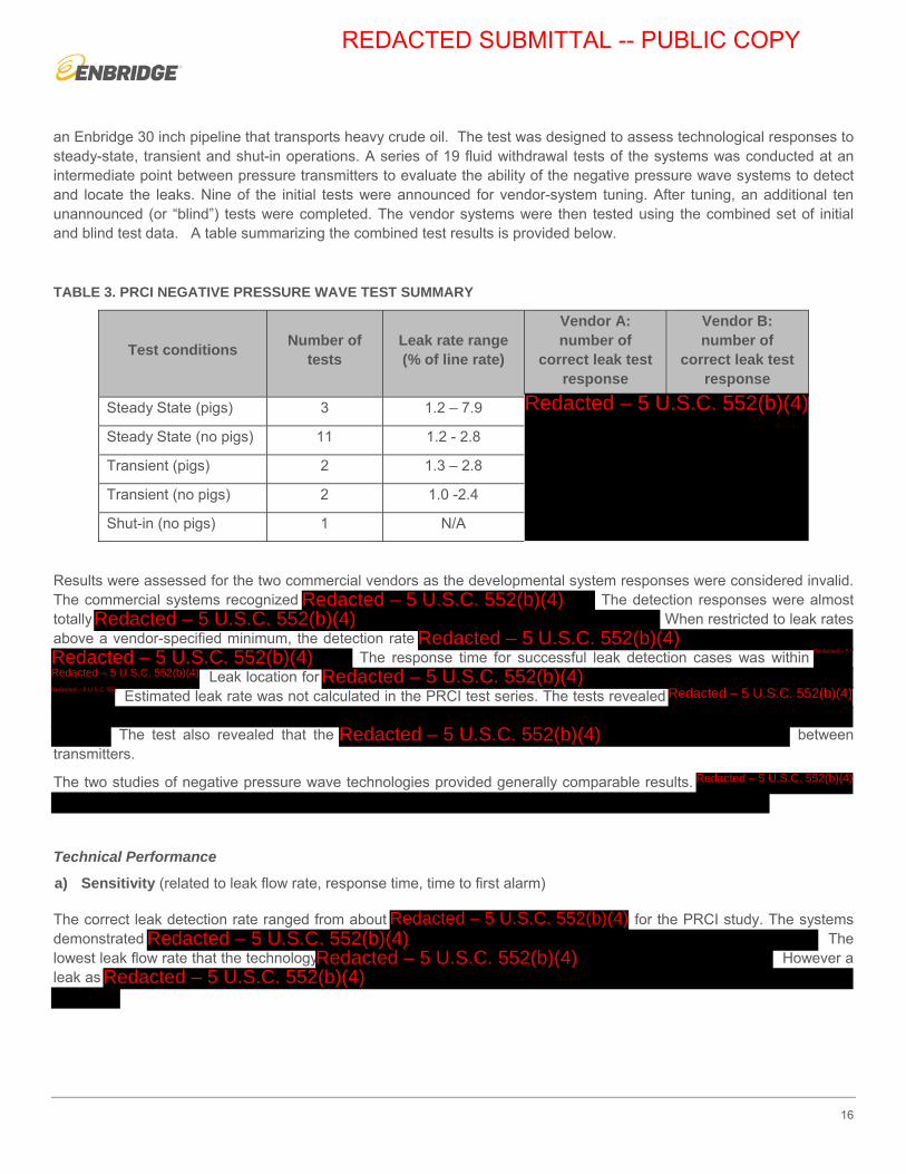
an Enbridge 30 inch pipeline that transports heavy crude oil. The test was designed to assess technological responses to steady-state, transient and shut-in operations. A series of 19 fluid withdrawal tests of the systems was conducted at an intermediate point between pressure transmitters to evaluate the ability of the negative pressure wave systems to detect and locate the leaks. Nine of the initial tests were announced for vendor-system tuning. After tuning, an additional ten unannounced (or “blind”) tests were completed. The vendor systems were then tested using the combined set of initial and blind test data. A table summarizing the combined test results is provided below.
TABLE 3. PRCI NEGATIVE PRESSURE WAVE TEST SUMMARY
Test conditions Number of
tests Leak rate range (% of line rate)
Vendor A: number of
correct leak test response
Vendor B: number of
correct leak test response
Steady State (pigs) 3 1.2 – 7.9
Steady State (no pigs) 11 1.2 - 2.8
Transient (pigs) 2 1.3 – 2.8
Transient (no pigs) 2 1.0 -2.4
Shut-in (no pigs) 1 N/A
Results were assessed for the two commercial vendors as the developmental system responses were considered invalid. The commercial systems recognized The detection responses were almost totally When restricted to leak rates above a vendor-specified minimum, the detection rate
The response time for successful leak detection cases was within Leak location for
Estimated leak rate was not calculated in the PRCI test series. The tests revealed
The test also revealed that the between transmitters.
The two studies of negative pressure wave technologies provided generally comparable results.
Technical Performance
a) Sensitivity (related to leak flow rate, response time, time to first alarm)
The correct leak detection rate ranged from about for the PRCI study. The systems demonstrated The lowest leak flow rate that the technology However a leak as
REDACTED SUBMITTAL -- PUBLIC COPY
Redacted – 5 U.S.C. 552(b)(4)
Redacted – 5 U.S.C. 552(b)(4)Redacted – 5 U.S.C. 552(b)(4)
Redacted – 5 U.S.C. 552(b)(4)Redacted – 5 U.S.C. 552(b)(4) Redacted – 5 U.S.C. 552(b)(4)
Redacted – 5 U.S.C. 552(b)(4) Redacted – 5 U.S.C. 552(b)(4)Redacted – 5 U.S.C. 552(b)(4) Redacted – 5 U.S.C. 552(b)(4)
Redacted – 5 U.S.C. 552(b)(4)
Redacted – 5 U.S.C. 552(b)(4)
Redacted – 5 U.S.C. 552(b)(4)Redacted – 5 U.S.C. 552(b)(4)
Redacted – 5 U.S.C. 552(b)(4)Redacted – 5 U.S.C. 552(b)(4)
17
b) Reliability (Number of False alarms)
c) Accuracy (Leak location detection, total volume lost, leak rate estimation)
d) Robustness (function under AOC, instrument outage, fault tolerance)
Feasibility and Limitations
a) Constructability
Pressure wave technology requires the use of high quality pressure process data within a pipeline segment from sensors that are not isolated by valves or in-line devices such as pigs. Existing Enbridge pipelines could be retrofitted with these additional transmitters but they would have to be located on both sides of all operational pipeline block valves in the segment being monitored. Power and high-speed communications would have to be provided at each pressure transmitter location.
REDACTED SUBMITTAL -- PUBLIC COPY
Redacted – 5 U.S.C. 552(b)(4)
Redacted – 5 U.S.C. 552(b)(4)
Redacted – 5 U.S.C. 552(b)(4)
Redacted – 5 U.S.C. 552(b)(4)

18
b) Practicality
This system would not be practical for deployment on a full pipeline. However, for pipeline segments lengths of <50 km (the system’s limitation), this system would be a practical choice when compared to other technological systems that are much more difficult to implement.
c) Maturity
The existing system is a passive one which analyzes pressure waves created by leaks. A new version of the technology could be investigated to assess the principle of actively analyzing a pressure wave which could be created at regular intervals. A new approach for pressure wave technology was identified by PRCI investigation as a potential new solution, which could be based on an active system identifying leaks based on acoustic attenuation or reflection.
Underwater Feasibility Consideration
Negative pressure wave technology and the level of sensitivity that can be achieved for a given subsea condition with this technology is still a question that needs additional testing and evaluation. To do this, an LDS which integrates negative pressure wave technology with flow measurements was enabled on November, 2016 at L5 from North Straits to Indian River. The reliability of this test system is currently being monitored and assessed.
Future Steps
Enbridge is assessing a negative pressure wave technology as a part of an integrated LDS on Line 5 at the Straits of Mackinac. Enbridge is still evaluating the testing of this technology and will provide the summary of results as part of its report on the feasibility of installing external LDS at the Straits of Mackinac which is due 180 Days after the effective date or November 19, 2017.
AERIAL TECHNOLOGY
General Applicability and Use
This technology is used primarily for mainline leak detection, but can be applied to some applications at facilities (e.g. terminals and pump stations) as well.
Aerial leak detection sensors have the potential to supplement existing pipeline surveys. Traditional visual right of way inspections often rely on changes in vegetation or visible “pools” of oil on the ground to detect a release. Ideally, aerial based leak detection sensors can be used to detect these leaks before they come to surface. Subsurface liquid hydrocarbon leak signatures can be present in many forms, such as VOC gas plumes, temperature differentials between the oil and the soil, as well as ground subsidence or ground heave.
Evaluation Status to Date
In 2012, PRCI with the participation of Enbridge, conducted a field study on two of Enbridge’s natural gas gathering lines located near Mineral Wells, Texas, to evaluate the performance of the existing sensor technologies for detecting gas and oil leaks on pipelines. A series of controlled natural gas releases from eight locations were staged along the pipeline in order to simulate gas leaks. Additionally, eight liquid petroleum containers as targets were placed along the test pipelines. Since the participating vendors were optimized to detect methane gas, the findings for liquid leak detection were
REDACTED SUBMITTAL -- PUBLIC COPY
Redacted – 5 U.S.C. 552(b)(4)

19
inconclusive due to overlaps between gas and oil targets. Therefore, additional studies for conclusion on liquid leak detection technologies were needed.
In 2013, Enbridge contracted C-FER to evaluate the effectiveness of aerial based leak detection technologies to identify a liquid hydrocarbon leak from an operating pipeline. C-FER completed a comprehensive market survey to determine the status of current aerial leak detection technologies. The survey determined that the primary focus of aerial leak detection vendors was on natural gas pipelines (with the focus to detect methane), and not liquid pipelines. As a result, limited information was available regarding the ability to detect leaks from liquid pipelines. It also showed that most of the aerial leak detection sensors claim VOC concentration detection limits (usually in terms of methane or total hydrocarbons) in parts per million (ppm) with some as low as parts per billion (ppb).
To generate a baseline to evaluate vendor technology claims, to complete lab scale soil column testing and numerical modeling. The primary focus of this testing was to determine which VOC species would migrate to the soil surface from a subsurface leak; as well as identify the variation in their respective concentrations over time. results showed pentane (C5) as the dominant species generated from a subsurface liquid leak. It also showed that VOC concentrations generated from a subsurface liquid hydrocarbon release were multiple orders of magnitude lower than the
In 2015, a JIP was established to continue the work already completed by Enbridge and to obtain a better understanding of the available technologies for aerial based pipeline leak detection for liquid pipelines. The first task completed under the Aerial leak detection JIP was to benchmark the numerical models developed by as described above. C-FER completed lab testing to quantify the concentrations of VOCs at the soil surface and temperature differentials produced in ELDER test apparatus during multiple simulated leak events. These results were then compared to the modeling results and used to re-evaluate the vendor capabilities to detect liquid leaks. The lab testing results agreed with the results of the numerical models, with the model estimating VOC concentrations in the same order of magnitude measured during ELDER testing. Both cases observed that methane was present,
Since most of the available sensors in the market are
Building on the previous numerical models and expertise, expanded the model to gain a greater understanding of possible leak signatures present from a sub-surface liquid hydrocarbon release. The focus of the numerical modeling has been on the following four primary leak signatures:
• Dilbit migration
• VOC migration and plume dispersion1
• Temperature differential
• Ground subsidence/heave
Utilizing the knowledge developed through the initial market survey completed with Enbridge and the experimental and modeling work, C-FER completed a follow-up detailed vendor survey. The survey covered commercial sensors; as well as those in the research and development stage. Each vendor was sent a request for information to provide more detail about their sensor and services. These vendors were scored based on evaluation criteria developed by the project
1 The dispersion of gaseous plume in the atmosphere which is affected by wind, ambient temperature, etc. called plume dispersion.
REDACTED SUBMITTAL -- PUBLIC COPY
Redacted – 5 U.S.C. 552(b)(4)
Redacted – 5 U.S.C. 552(b)(4)
Redacted – 5 U.S.C. 552(b)(4)
Redacted – 5 U.S.C. 552(b)(4)
Redacted – 5 U.S.C. 552(b)(4)
Redacted – 5 U.S.C. 552(b)(4)
Redacted – 5 U.S.C. 552(b)(4)

20
members. The higher scored vendors were selected for further evaluations. Table below shows the criteria used for ranking the vendors:
TABLE 4. AERIAL VENDOR RANKING CRITERIA
Vendor Ranking Criteria
Probability of detecting a leak based on lab data (i.e. ppm, temperature, heave)
Readiness of survey results (i.e. real time, 8 hours, 24 hours, etc.)
Experience with liquid pipeline surveys
Technology readiness (i.e. commercial, R&D etc.)
Probability of false positives
Sensor performance limitations
Vendor progressiveness
Performance in third party trials
Probability of sensor being miniaturized for Autonomous Underwater Vehicles (AUV)
Daily ROW coverage & distance resolution of leaks
Feedback from references
A small scale field testing was performed in 2016 to evaluate the performance of the volunteered aerial based VOC detection vendors.
Technical Performance Findings
Market Survey Results:
From the market survey, five (5) primary sensor types were identified. Further information on these sensors is provided below:
a) Laser Absorption – A laser is tuned to the absorption wavelength of the gas of interest. When the laser passes through a gas plume, some of the beam’s energy is preferentially absorbed. This weakens the return signal of the laser, which is measured by the instrument. Some of the characteristics of laser absorption leak detection are:
b) Ambient Light Absorption – Gas filter correlation radiometry can be used to determine the presence of a particular gas in the atmosphere. The instrument consists of two cells; one is an evacuated cell that acts as a reference, while the other contains a sample of air which may contain the gas of interest. Ambient light is used as the energy
REDACTED SUBMITTAL -- PUBLIC COPY
Redacted – 5 U.S.C. 552(b)(4)

21
source and passes through both cells. The instrument measures the difference in energy between the two cells, which is directly proportional to the concentration of the gas of interest. Some of the characteristics of ambient light absorption are:
c) Flame Ionization – The sensor collects a sample of the ambient air and burns it in a hydrogen flame. The number of ions produced from this combustion process is proportional to the amount of hydrocarbon in the sample. Some of the characteristics of flame ionization detectors are:
d) Thermal Imaging –Infrared imaging is used to identify the temperature profile of the subject of interest. For the purpose of pipeline inspections, the infrared camera identifies temperature anomalies associated with a pipeline leak (i.e. temperature differential between the leaked fluid and the surrounding soil). Some of the characteristics of thermal imaging are:
e) LIDAR Heave/subsidence monitoring –The Light Detection and Ranging (LIDAR) unit sends pulses of light towards the surface it is mapping and is often used to map terrain with high resolution. It can determine the distance from the terrain by measuring the time it takes for the light to be reflected back to the sensor. Some of the characteristics of LIDAR terrain mapping are:
VOC Field Testing Results:
The testing program evaluated the VOC detection technologies in an idealized field environment using representative gas fluxes rather than full-scale liquid hydrocarbon releases. The technologies that were evaluated in this testing include:
• Open-path laser absorption: A laser signal tuned to the absorption wavelength of the gas of interest (i.e. pentane in this test) is emitted from a source toward the ground. The beam reflects off the ground will return to the sensor system where it can potentially detect the gas of interest.
REDACTED SUBMITTAL -- PUBLIC COPY
Redacted – 5 U.S.C. 552(b)(4)
Redacted – 5 U.S.C. 552(b)(4)
Redacted – 5 U.S.C. 552(b)(4)
Redacted – 5 U.S.C. 552(b)(4)

22
• Closed-path laser absorption: A laser signal tuned to the absorption wavelength of the gas of interest (i.e. pentane here) is emitted from a sensor towards a mirror positioned in-line on the same mounting plate approximately half a meter away. The mirror is angled in such a way that the laser signal bounces back and forth to increase its effective sampling path length. To detect the presence of pentane, the laser path must pass through the plume which includes pentane.
• Metal oxide semi-conductor sensor: In clean air, the current flowing through the sensor is limited due to the bonding of oxygen with the free electrons in the sensor element. In the presence of the gas of interest around the sensor (i.e. pentane in this case), the oxidation reaction allows the electrons to move freely across the sensor. The change in resistance of the sensor element is measured to determine the concentration of pentance surrounding the sensor.
To assess the performance of each VOC detection technology for liquid pipeline leaks, the setup exposed each sensor to low n-pentane (C5) concentrations (<150 ppm) in both closed and open environments. The vendor sensors were mounted to the underside of a boom-lift in order to achieve the desired testing elevations without the expense of logistical challenges of operating aircraft. A total of 65 pentane release events (including 19 baseline events with no pentane release) were completed in 4 different elevations from 1 to 8 m.
Due to rigorous techniques used to characterize the plume and local weather conditions, the data collected from the Photo Ionization Detector (PID) sensors in this test program can also be used to validate models of atmospheric dispersion of pentane in future. This model could be used to estimate expected VOC concentrations from different ground fluxes produced from a subsurface liquid hydrocarbon release. This information could be used to perform initial theoretical evaluations of other VOC detection technologies as a means of pre-screening vendors for future tests.
Thermal Camera Lab Testing Results:
The testing program evaluated the thermal camera sensors based on their ability to detect pinhole targets (2.5 mm to 44.5 mm in diameter) with varying temperature differentials (0.1-1 oC) from 45 m away in an idealized lab environment using controlled temperature differentials generated by a blackbody calibrator based on ASTM E1311-14.
Feasibility and Limitations
a) Constructability
REDACTED SUBMITTAL -- PUBLIC COPY
Redacted – 5 U.S.C. 552(b)(4)
Redacted – 5 U.S.C. 552(b)(4)

23
This would not require any construction by Enbridge, but would require the sensor to be fitted on an aircraft. Approvals for mounting sensors on an aircraft could be challenging to acquire from governing bodies such as the Federal Aviation Authority and/or Transport Canada. Some of the sensors can be mounted on a stationary structure for facility monitoring.
b) Practicality
This technology could be incorporated to the existing aircrafts with modifications if the sensors are further developed and proven to be effective, as Enbridge currently uses aircraft for aerial patrol. However, this would require the appropriate approvals as noted above.
c) Maturity
Based on the preliminary modeling and lab testing results,
Underwater Feasibility Consideration
At this stage, none of the aerial based technologies are able to detect liquid leaks on underground pipelines. Direct testing of aerial technologies was not evaluated for underwater pipelines
Future Steps
Thermal based sensor lab testing showed that a
FIBER OPTIC CABLE – DTS
General Applicability and Use
Distributed Temperature Sensing (DTS) Fiber Optic Cables are placed in the trench with an underground pipeline where leaks may be detected by measuring the temperature gradient between the leak and the surrounding soil. The fiber cable functions as a sensor and records the temperature profile over time. This information is relayed to software analytics that determine if there is a leak in the pipe.
Evaluation Status to Date
REDACTED SUBMITTAL -- PUBLIC COPY
Redacted – 5 U.S.C. 552(b)(4)
Redacted – 5 U.S.C. 552(b)(4)

24
DTS performance was evaluated in ELDER testing Phase 1 and 2 and further in Flanagan South Pilot (FSP). The results described below were obtained from both of the evaluation methods.
No underwater tests have been performed; thus, the performance of FOC systems in an underwater environment is unknown at this time. However, an ELDER test has been completed for a fully saturated soil environment.
Technical Performance
a) Sensitivity (related to leak flow rate, response time, time to first alarm)
Testing in ELDER demonstrated that the technology
The final results are expected to be complete in Q4 2017.
b) Reliability (Number of False alarm)
In 2015-2017 on a segment of the FSP, the reliability of DAS systems in an operational pipeline over an extended period of time (about a year and a half) was assessed. The pilot evaluation demonstrated that the false alarm count of DTS
c) Accuracy (Leak location detection, total volume lost, leak rate estimation)
Leak location evaluation was not within the scope of the ELDER but it was investigated relative to FSP operations. In locations with the proper calibration, the system was able to locate
e.
d) Robustness (function under AOC, instrument outage, fault tolerance)
DTS systems are only suitable for lines in which the temperature difference of surrounding soil and product is high enough (where temperature difference is greater than ±2°C) for the DTS system to be able to detect leaks. This technology also requires the leaked product to make contact with the cable (leak path dependent), so placement of the fiber with respect to the pipeline becomes a very important factor in its effectiveness as an LDS.
Feasibility and Limitations
a) Constructability
The constructability of this technology is challenging because the system sensors must be placed in the trench very close to the pipeline. Very accurate placement of cabling in a pipeline trench poses increased risk to workers and presents a safety concern. Constructability favors technologies that retain functionality even with uneven cable placement. The sensor effectiveness is highly path-dependent, thereby making constructability a critical issue. This technology is likely appropriate for new pipeline construction only.
REDACTED SUBMITTAL -- PUBLIC COPY
Redacted – 5 U.S.C. 552(b)(4)
Redacted – 5 U.S.C. 552(b)(4)
Redacted – 5 U.S.C. 552(b)(4)
Redacted – 5 U.S.C. 552(b)(4)
Redacted – 5 U.S.C. 552(b)(4)

25
b) Practicality
Once installed, the fiber optic cable may require periodic maintenance or experience issues due to settlement, and stress or strain causing micro-bends. The cables are located under the ground and are therefore challenging to access. The analytic system (software) should require minimal maintenance. However, the FOC can be shared for use with communications.
The technology is suitable only for lines in which the temperature difference of surrounding soil and released product is high enough to allow for detection by the DTS system (minimum ±2 °C temperature difference over the spatial resolution).
c) Maturity
This technology has been adapted from down-hole monitoring technology used for conventional wells. There are only a few installations around the world to date that use this technology for LD on oil pipelines.
Underwater Feasibility Consideration
DTS requires sufficient temperature difference between the fiber optic cable and the surrounding in order to alarm. This becomes even more challenging for underwater applications in which the temperature difference will disappear much quicker and the oil and surrounding water will quickly come into thermal equilibrium. In this case, if the sensor is right beside the leak there might be a chance of detection, otherwise the leak could be missed. Also, installation of fiber for underwater application, especially for retrofit scenarios is a complex and is not a well-understood practice. This technology is not recommended for underwater applications
Future Steps
ELDER Phase 2 testing concluded in December 2016. One of the tests of Phase 2 focused on determining the functionality of multiple systems including DTS in a fully water saturated soil environment.
The final results are expected to be complete in Q4 2017.
FIBER OPTIC CABLE – DAS
General Applicability and Use
Distributed Acoustic Sensing (DAS) fiber optic cables are placed in the trench with an underground pipeline and by detecting its acoustic noise; a small leak may be detected. The cable functions as a sensor and analyzes the sound profile in the time and frequency domains. This information is relayed to software that determines if there are leaks in the pipe. Some DAS systems also incorporate the sensing of a temperature differential that is associated with a leak, similar to the DTS systems. This technology has an ancillary benefit of providing third party intrusion monitoring for security and to detect theft.
Evaluation Status to Date
REDACTED SUBMITTAL -- PUBLIC COPY
Redacted – 5 U.S.C. 552(b)(4)
Redacted – 5 U.S.C. 552(b)(4)
Redacted – 5 U.S.C. 552(b)(4)

26
DAS performance was evaluated in ELDER testing Phase 1 and 2 and further in FSP. The results described below were obtained from both of the evaluation methods.
No underwater tests have been completed with these systems, so its performance in an underwater environment is unknown at this time. However, an ELDER test has been completed for fully saturated soil environment.
Technical Performance
a) Sensitivity (related to leak flow rate, response time, time to first alarm)
Testing in ELDER demonstrated that the technology
The final
results are expected to be complete in Q4 2017.
b) Reliability (Number of False alarm)
In addition to the leak simulated events, some events called as “dummy events” were executed in ELDER to evaluate the reliability of DAS technology. The “dummy events” were created in ELDER by generating acoustic noises without releasing any products.
In 2015-2017 on a segment of the FSP, the reliability of DAS systems was assessed in an operational pipeline over an extended period of time (about a year and a half). After extensive tuning of the DAS system to the local environmental and operational conditions,
c) Accuracy (Leak location detection, total volume lost, leak rate estimation)
Leak location evaluation was not within the scope of the ELDER, but was investigated during FSP.
d) Robustness (function under AOC, instrument outage, fault tolerance)
The final results are expected to be complete in Q4 2017.
DAS performance is less prone to degradation due to a change in the release location or FOC position because it does not require contact with leaked product. Thus, performance is not as dependent on FOC position, as compared to DTS. This provides some installation flexibility for the DAS FOC.
Feasibility and Limitations
REDACTED SUBMITTAL -- PUBLIC COPY
Redacted – 5 U.S.C. 552(b)(4)
Redacted – 5 U.S.C. 552(b)(4)
Redacted – 5 U.S.C. 552(b)(4)
Redacted – 5 U.S.C. 552(b)(4)
Redact - 5 USC 552(b)(4)

27
a) Constructability
The constructability of this technology is challenging because these sensors must be located in the trench with the pipeline. The FOC placement is less challenging than for DTS because the technology is not path-dependent and can be placed in a conduit for more flexible installation, thereby allowing a safer environment for personnel and equipment. This technology is appropriate for new pipeline construction.
b) Practicality
The FOCs are located under the ground and are therefore challenging to access.
c) Maturity
This technology has been in use for third-party intrusion and security in the oil and gas industry, and has recently been adapted for use in LDS. There are only a limited number of installations in use for oil pipelines,
Underwater Feasibility Application
Enbridge completed a concept study in 2014 for LD and threat prevention at the Straits of Mackinac; as well as LD at the Straits of Mackinac Crossing using cable based technologies. It was investigated whether a cable-based external LDS would be principally effective and sensitive for monitoring the dual Line 5 pipelines crossing the Straits of Mackinac.
Future Steps
In 2017, Enbridge will complete the following activities to further assess the use of DAS on liquid pipelines:
• Complete installation of DAS technology on a segment of Norlite Pipeline to monitor 32 km of ROW and a major river crossing.
• Continue to study the technology’s leak detection benefits, and the construction feasibility of deploying fiber optic cable across the Straits of Mackinac on Line 5.
• Participate as an industry member in a new PRCI research initiative on field testing of DAS technology.
• ELDER Phase 2 testing concluded in December 2016 with two tests and focused on attaining a more comprehensive understanding of the technologies and their limitations, with a primary focus on DAS Technology.
The final results are expected to be complete in Q4 2017.
VAPOR SENSING TUBE (VST)
General Applicability and Use
REDACTED SUBMITTAL -- PUBLIC COPY
Redacted – 5 U.S.C. 552(b)(4)
Redacted – 5 U.S.C. 552(b)(4)
Redacted – 5 U.S.C. 552(b)(4)
28
Vapor Sensing Tube (VST) technologies are effective gas analyzing systems that obtain gas samples from sensing tubes placed along the length of the pipeline. During a leak, hydrocarbon vapors permeate through the soil and diffuse into the tube causing a high vapor concentration in the tube. Once or twice per day the contents of the tube are purged and a gas analyzer will detect the vapor location.
Evaluation Status to Date
VST performance was evaluated in ELDER testing Phase 1 and 2. No underwater tests have been conducted with these systems, and thus the performance of these systems in an underwater environment is unknown at this time. However, an ELDER test has been completed for fully water saturated soil environment.
Technical Performance
a) Sensitivity (related to leak flow rate, response time, time to first alarm)
he final results are
expected to be complete in Q4 2017.
b) Reliability (Number of False alarm)
Frequency of false alarms would require further investigation.
c) Accuracy (Leak location detection, total volume lost, leak rate estimation)
Leak location was not within the scope of the ELDER and would require further investigation through an evaluation install.
d) Robustness (function under AOC, instrument outage, fault tolerance)
Feasibility and Limitations
a) Constructability
The constructability of this technology is somewhat challenging because these sensors must be placed along the pipeline, anywhere in trench floor or near the soil surface on top of the pipe. The VST must be placed in a perforated conduit and would be required to be strapped to the pipe at any Horizontal Directional Drill (HDD) locations. It is ideal for the sensor
REDACTED SUBMITTAL -- PUBLIC COPY
Redacted – 5 U.S.C. 552(b)(4)
Redacted – 5 U.S.C. 552(b)(4)
Redacted – 5 U.S.C. 552(b)(4)

29
cable to be installed during new pipeline construction. Although, it may be retrofitted at higher construction cost for existing pipelines applications.
b) Practicality
Since the tubes are located under the ground there are access challenges related to maintenance. Facilities for installation of pump and gas analyzer are required approximately every 10 km.
c) Maturity
This LD technology has been used with oil facilities and some pipelines worldwide, and is a mature product.
Underwater Feasibility Consideration
Performance of VST in underwater conditions will be degraded drastically due to the fact that vapors diffuse in water much slower than in a dry soil unless the VST tube comes into direct contact with liquid hydrocarbon release. The level of sensitivity that can be achieved for a given subsea condition is still a question which needs more testing and evaluation. The installation of VST cable for underwater application, especially for retrofit scenarios are a complex task and is not a well-understood practice. This technology is not recommended for underwater applications.
Future Steps
ELDER Phase 2 testing concluded in December 2016. One of the tests in Phase 2 focused on determining the functionality of multiple systems including VST in a fully water saturated soil environment.
he final results are
expected to be complete in Q4 2017.
HYDROCARBON SENSING CABLE (HSC)
General Applicability and Use
This technology is used primarily for Facilities leak detection with some localized mainline applications. In Hydrocarbon Sensing Cable (HSC) systems, a cable is place alongside an underground pipeline in a buried trench. The cable has electrical properties and will change when it comes into contact with released liquid hydrocarbon. When the cable properties change, electrical signals are sent to software through the cable and leak location is then determined.
Evaluation Status to Date
REDACTED SUBMITTAL -- PUBLIC COPY
Redacted – 5 U.S.C. 552(b)(4)
Redacted – 5 U.S.C. 552(b)(4)
Redacted – 5 U.S.C. 552(b)(4)

30
HSC performance was evaluated in ELDER testing Phase 1 and 2. No underwater tests have been completed with these systems. Performance of these systems in an underwater environment is unknown at this time. However, an ELDER test in Phase 2 has been completed for fully water saturated soil environment.
Reliability performance of a selected HSC vendor was assessed through an installation for underground flange leak detection at Roundhill Station.
Technical Performance
a) Sensitivity (related to leak flow rate, response time, time to first alarm)
Testing in ELDER showed that in dry soil,
For water saturated environments,
ince the oil is lighter than water, and direct contact with the liquid hydrocarbon is needed, the sensing cable should be placed on top of the pipe to increase the chance of success in detection. . The final results are expected to be complete in Q4 2017.
b) Reliability (Number of False alarm)
c) Accuracy (Leak location detection, total volume lost, leak rate estimation)
Leak location was not within the scope of the ELDER.
d) Robustness (function under AOC, instrument outage, fault tolerance)
Feasibility and Limitations
a) Constructability
HSC systems rely on direct contact with liquid hydrocarbons and thus must be placed at locations where oil is likely to collect upon leaking.
REDACTED SUBMITTAL -- PUBLIC COPY
Redacted – 5 U.S.C. 552(b)(4)
Redacted – 5 U.S.C. 552(b)(4)
Redacted – 5 U.S.C. 552(b)(4)
Redacted – 5 U.S.C. 552(b)(4)
Redacted – 5 U.S.C. 552(b)(4)
Redacted – 5 U.S.C. 552(b)(4)

31
For new pipeline construction, installation of this technology is challenging as these sensors must be placed in the trench very close to the pipeline. This technology is difficult to retrofit for mainline pipelines.
In general, once the sensor has been affected by hydrocarbon, ne of the challenges is that these
require slotted conduit installed during construction, with a hand-hole2 approximately every 200m. This would be required to pull in the HSC while not exceeding the allowable tensile load of the HSC during install. Additional excavations for hand-holes are costly and challenging on pipeline ROW. Adding many hand-holes is expected to compound the already complex process of pipeline construction.
b) Practicality
This technology is best-suited for facility and localized mainline application. Due to the fact that a sensor must be placed every 200m in a hand-hole, it is prohibitive to install this technology in a long distance mainline or HDD scenario. However, the technology could be managed on a facility and on very short segments of pipe. The HSC must be replaced once it comes into contact with any hydrocarbon.
For new pipeline construction, the cables are located below grade and are therefore challenging to access. HSC systems are generally used for a localized range. Each segment is independent of all other segments along the pipeline and many segments are arranged back to back along the pipe run to achieve the desired covered length or branching configuration.
c) Maturity
The LD technology is fully mature and has been used in the oil and gas and air transportation industries to detect hydrocarbons.
Underwater Feasibility Consideration
This technology needs direct contact with liquid hydrocarbons therefore the HSC cable must be placed at location where oil is likely to collect upon leaking. This makes it even more challenging for underwater applications in which currents and water movement may change the leak path and avoid contact with the HSC cable. The level of sensitivity that can be achieved for a given subsea condition is still a question which needs more testing and evaluation. Also, installation of HSC cable for underwater application, especially for retrofit scenarios is not a straight forward task or well-understood practice. At this point, the technology is not suitable for underwater operational use.
Future Steps
ELDER Phase 2 testing concluded in December 2016. One of the tests conducted in Phase 2 focused on determining the functionality of multiple systems including HSC in a fully water saturated soil environment
The final results are expected to be complete in Q4 2017.
2 A hand-hole is an underground vault with a detachable cover that provides a junction for conduits/cables coming from different directions and is the location where splicing of cables take place. Hand-holes provide access to the system for maintenance.
REDACTED SUBMITTAL -- PUBLIC COPY
Redacted – 5 U.S.C. 552(b)(4)
Redacted – 5 U.S.C. 552(b)(4)
Redacted – 5 U.S.C. 552(b)(4)

32
POLYMER ABSORPTION SENSOR (PAS)
General Applicability and Use
PAS sensor that is made from a polymer that has a resistance change due to the material swelling in the presence of hydrocarbons. The sensor will react to both hydrocarbon liquids and vapors (non-methane).
The sensor does not react to methane vapors, which is seen as a positive because the sensor will not otherwise generate false alarms as a result of naturally occurring methane in the environment.
A cable-based application of this technology is still in development and no commercial product yet exists. Enbridge is supporting the product development project through the PRCI consortium. The goal of the project is to develop and commercialize the PAS sensor cable that can be deployed on new and existing pipelines and can identify small underground hydrocarbon leaks in real time. The cable will provide power and communications to a network of nodes where each node can be outfitted with various sensor types such as hydrocarbon detection sensors, vibration sensors, temperature sensors. This work will include evaluating design specifics, participating in the development of deployment protocols that are aligned with industry practices and expectations, formulating test bed soil scenarios that closely resemble real world conditions, vetting test results, designing practical maintenance procedures, and optimizing the technology package for rapid adoption.
Evaluation Status to Date
A preliminary prototype PAS sensor was evaluated for sensitivity in one of the tests of ELDER Phase 1 (i.e. Test 3) in 2014 in conjunction with PRCI. The cable based PAS sensor idea has been presented and approved by PRCI for a long term product development project running through 2016-2018. This project also received additional funding through
Enbridge is a member of the current PRCI project team monitoring and testing the
Components of this ongoing PRCI project include engineering design studies, additional prototype version development and an extensive field test plan. Initial PAS field testing has been initiated in June, 2017 and be completed in 2018. This testing involves assessing the PAS detection capabilities for various fluid type and soil conditions. There will be 24 soil condition cases tested using 5 fluid types. The technical performance criteria of this technology for sensitivity, reliability, accuracy and robustness are uncertain and need to be assessed from the PRCI field test project results.
Technical Performance
a) Sensitivity (related to leak flow rate, response time, time to first alarm)
When the preliminary prototype tested in ELDER as part of Phase 1, the sensor
b) Reliability (Number of False alarm)
REDACTED SUBMITTAL -- PUBLIC COPY
Redacted – 5 U.S.C. 552(b)(4)
Redacted – 5 U.S.C. 552(b)(4)
Redacted – 5 U.S.C. 552(b)(4)
Redacted – 5 U.S.C. 552(b)(4)
Redacted – 5 U.S.C. 552(b)(4)

33
The PAS sensor does not react to methane vapors, which will reduce false alarms that may otherwise occur as a result of the presence of naturally occurring methane in the environment. The technology is still under development and there is no installed system that can be monitored for reliability.
c) Accuracy (Leak location detection, total volume lost, leak rate estimation)
d) Robustness (function under AOC, instrument outage, fault tolerance)
The PAS sensor is non-reversible and needs to be removed and replaced if submerged in hydrocarbon liquid. Because the sensor detects vapors as well as liquids, the sensor need not be placed immediately adjacent to the pipeline, so there is possibility of retrofit.
Feasibility and Limitations
PAS sensors require more evaluation and/or product development to determine feasibility characteristics.
Underwater Feasibility Consideration
The performance of this technology in various conditions including fully saturated soil is under evaluation with PRCI. At this stage, the technology is immature for any application including underwater and is not ready for operational use.
Future Steps
The PRCI-sponsored project was initiated in 2015 with support. The goals include development of the advanced PAS cable prototype by 2017. The project includes development of a field test site and testing completion by 2018.
Conclusions and Next Steps
There are seven ALD technologies that Enbridge has been evaluating which include: negative pressure wave, aerial technology, Distributed Temperature Sensing (DTS) cables, Distributed Acoustic Sensing (DAS) cables, Vapor Sensing Tube (VST), Hydrocarbon Sensing Cables (HSC) and Polymer Absorption Sensors (PAS).
In its evaluation, Enbridge has implemented the following approaches to identify the feasibility of the technology within the Enbridge pipeline leak detection program: (1) implementing internal Enbridge field tests and pilots; (2) participation as a supporting member in the Pipeline Research Council International (PRCI); and (3) through Joint Industry Partnerships (JIP) with industry partners. A major JIP initiative specifically for ALD evaluation was the construction of the External Leak Detection Experimental Research (ELDER) apparatus. ELDER was used for many of the technology assessments identified in this report and continues to be a focus for ongoing testing.
REDACTED SUBMITTAL -- PUBLIC COPY
Redacted – 5 U.S.C. 552(b)(4)
Redacted – 5 U.S.C. 552(b)(4)
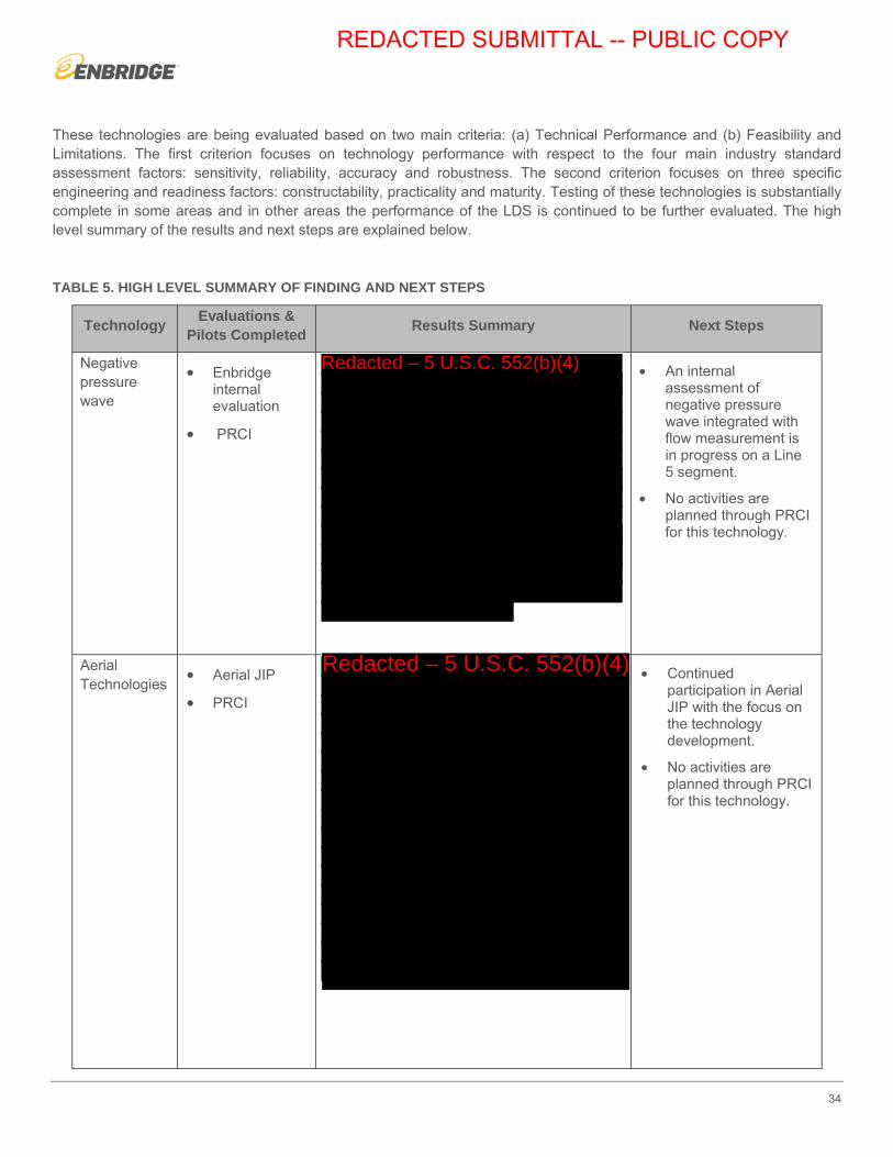
34
These technologies are being evaluated based on two main criteria: (a) Technical Performance and (b) Feasibility and Limitations. The first criterion focuses on technology performance with respect to the four main industry standard assessment factors: sensitivity, reliability, accuracy and robustness. The second criterion focuses on three specific engineering and readiness factors: constructability, practicality and maturity. Testing of these technologies is substantially complete in some areas and in other areas the performance of the LDS is continued to be further evaluated. The high level summary of the results and next steps are explained below.
TABLE 5. HIGH LEVEL SUMMARY OF FINDING AND NEXT STEPS
Technology Evaluations & Pilots Completed Results Summary Next Steps
Negative pressure wave
• Enbridge internal evaluation
• PRCI
• An internal assessment of negative pressure wave integrated with flow measurement is in progress on a Line 5 segment.
• No activities are planned through PRCI for this technology.
Aerial Technologies • Aerial JIP
• PRCI
• Continued participation in Aerial JIP with the focus on the technology development.
• No activities are planned through PRCI for this technology.
REDACTED SUBMITTAL -- PUBLIC COPY
Redacted – 5 U.S.C. 552(b)(4)
Redacted – 5 U.S.C. 552(b)(4)Redacted – 5 U.S.C. 552(b)(4)
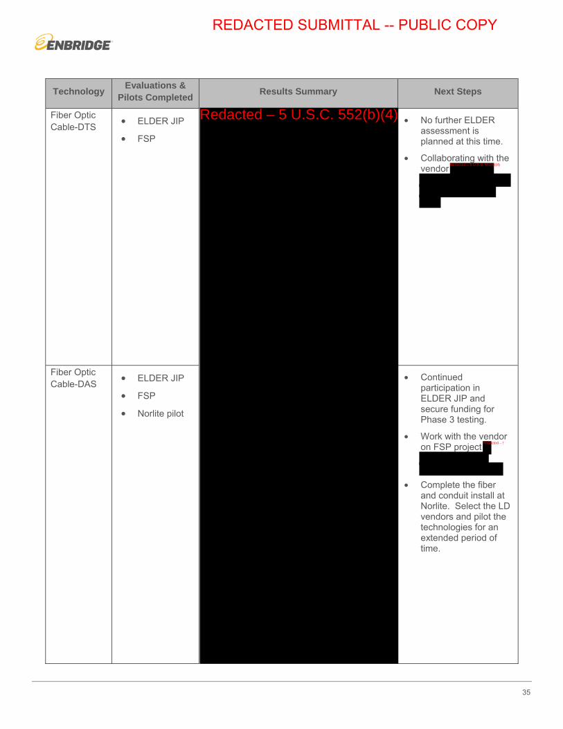
35
Technology Evaluations & Pilots Completed Results Summary Next Steps
Fiber Optic Cable-DTS • ELDER JIP
• FSP
• No further ELDER assessment is planned at this time.
• Collaborating with the vendor
Fiber Optic Cable-DAS • ELDER JIP
• FSP
• Norlite pilot
• Continued participation in ELDER JIP and secure funding for Phase 3 testing.
• Work with the vendor on FSP project
• Complete the fiber and conduit install at Norlite. Select the LD vendors and pilot the technologies for an extended period of time.
REDACTED SUBMITTAL -- PUBLIC COPY
Redacted – 5 U.S.C. 552(b)(4)
Redacted – 5 U.S.C. 552(b)(4)
Redacted – 5 U.S.C. 552(b)(4)

36
Technology Evaluations & Pilots Completed Results Summary Next Steps
Vapor Sensing Tube (VST)
• ELDER JIP • No further ELDER activities are planned at this time.
Hydrocarbon Sensing Cable (HSC)
• ELDER,
• Roundhill installation
• No further ELDER activities are planned at this time.
• No further HSC assessment is currently planned at Roundhill.
Polymer Absorption Sensor (PAS)
• PRCI • Continued participation in the PRCI project.
REDACTED SUBMITTAL -- PUBLIC COPY
Redacted – 5 U.S.C. 552(b)(4)

37
Reports Previously Submitted to PHMSA Regarding ALD Technology
The following reports were submitted to PHMSA as part of the Lakehead Plan. The documents outline the ALD technologies being investigated throughout the execution of the Lakehead Plan.
TABLE 6. LIST OF REPORTS PREVIOUSLY SUBMITTED TO PHMSA
Document Title Publication date Development Since Submissions
PRCI Field Testing of Negative-Wave Leak Detection Systems (Catalog No. PR-015-123713-R01)
Note: this report was originally titled Field Testing of Acoustic Leak Detection Systems
Feb 11, 2013 Discussed in Negative Pressure Wave Technology section within this ALD report
PRCI Enbridge Mineral Wells Study Final Report 071313
July 13, 2013 Discussed in Aerial Technology section within this ALD report
Multivendor Evaluation of In Line Acoustic Leak Detection Tools
June 13, 2013 This technology was out of the scope of this ALD report
REDACTED SUBMITTAL -- PUBLIC COPY
Redacted – 5 U.S.C. 552(b)(4)