Embed Size (px)
Citation preview
1
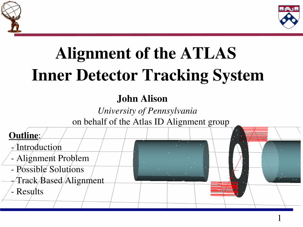
Alignment of the ATLAS Inner Detector Tracking System
Outline: Introduction Alignment Problem Possible Solutions Track Based Alignment Results
John Alison University of Pennsylvaniaon behalf of the Atlas ID Alignment group
2
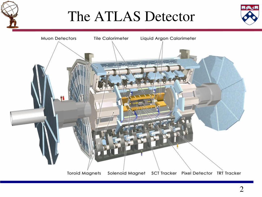
The ATLAS Detector
3
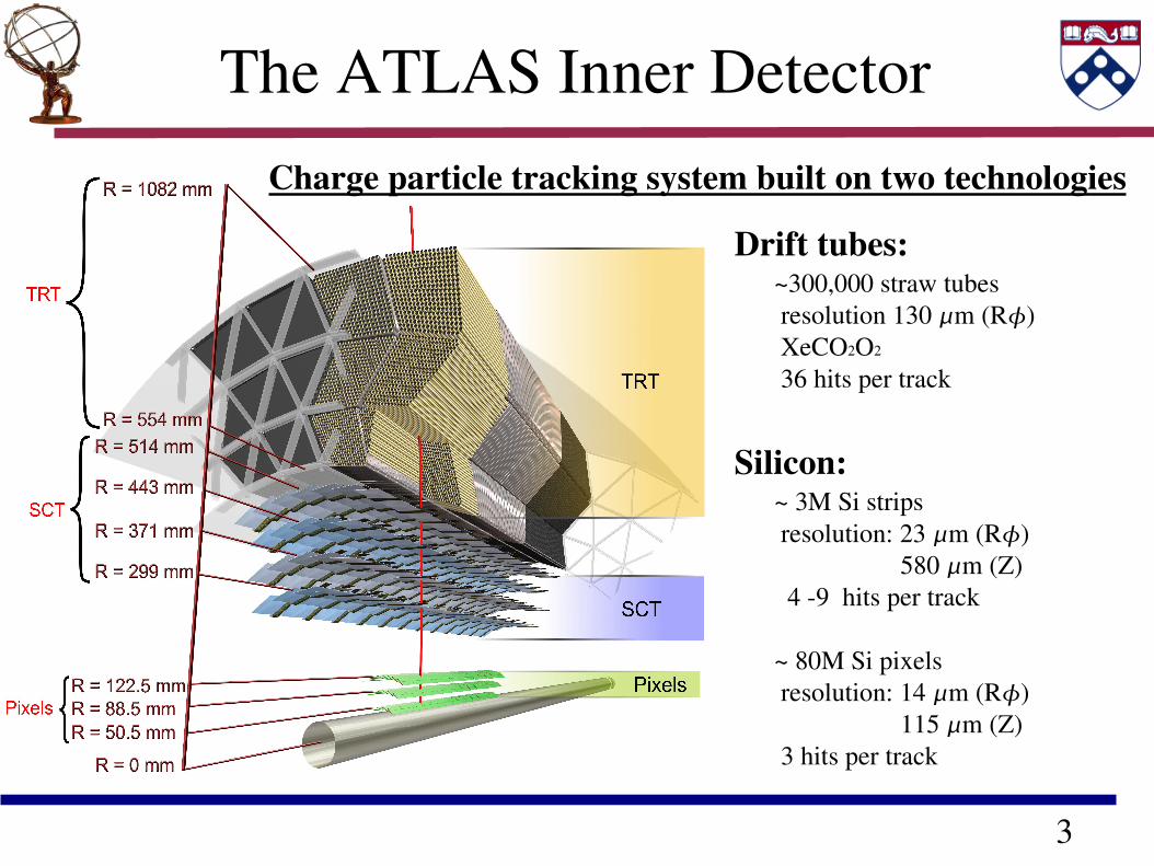
The ATLAS Inner DetectorCharge particle tracking system built on two technologies
Drift tubes: ~300,000 straw tubes resolution 130 m (R) XeCO2O2
36 hits per track
Silicon: ~ 3M Si strips resolution: 23 m (R) 580 m (Z) 4 9 hits per track ~ 80M Si pixels resolution: 14 m (R) 115 m (Z) 3 hits per track
4
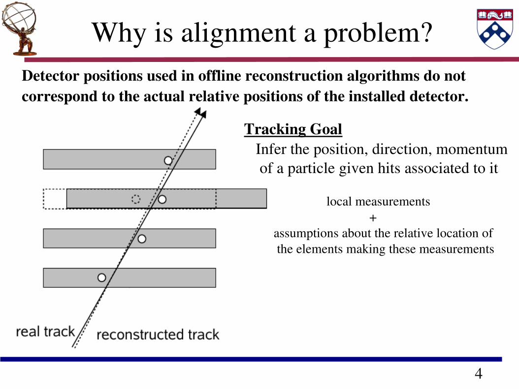
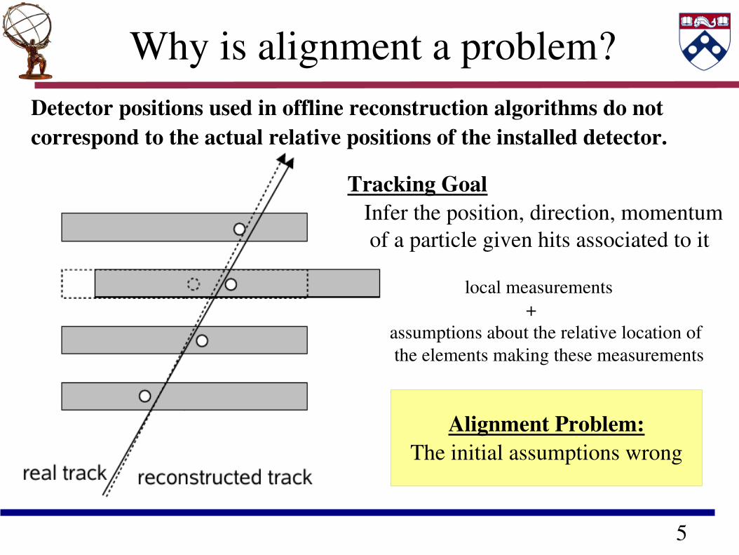
Detector positions used in offline reconstruction algorithms do not correspond to the actual relative positions of the installed detector.
Why is alignment a problem?
Tracking Goal Infer the position, direction, momentum of a particle given hits associated to it
local measurements + assumptions about the relative location of the elements making these measurements
5
Alignment Problem:The initial assumptions wrong
Detector positions used in offline reconstruction algorithms do not correspond to the actual relative positions of the installed detector.
Why is alignment a problem?
Tracking Goal Infer the position, direction, momentum of a particle given hits associated to it
local measurements + assumptions about the relative location of the elements making these measurements
6
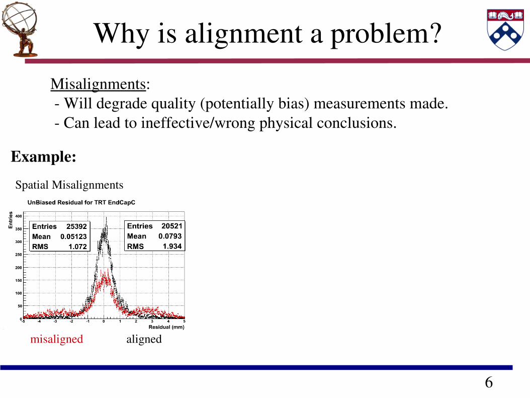
Why is alignment a problem?
Spatial Misalignments
misaligned aligned
Misalignments: Will degrade quality (potentially bias) measurements made. Can lead to ineffective/wrong physical conclusions.
Example:
7
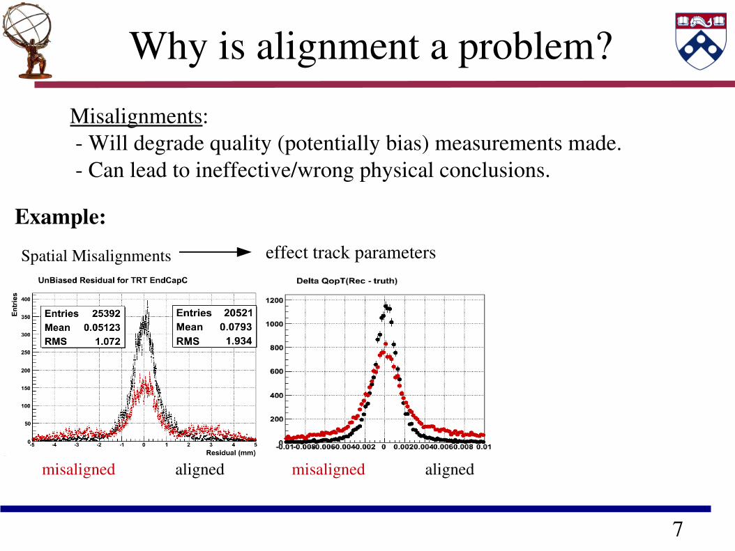
Why is alignment a problem?
Spatial Misalignments effect track parameters
misaligned aligned
misaligned aligned misaligned aligned
Misalignments: Will degrade quality (potentially bias) measurements made. Can lead to ineffective/wrong physical conclusions.
Example:
8
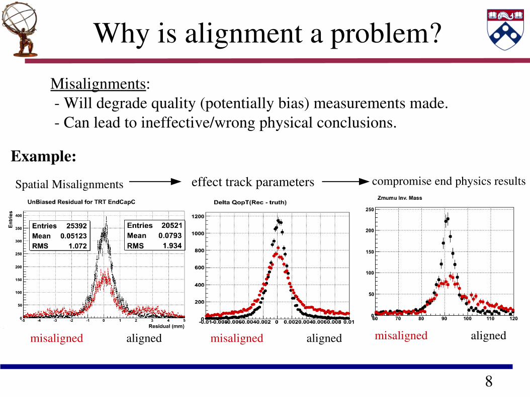
Why is alignment a problem?
Spatial Misalignments effect track parameters
misaligned aligned
compromise end physics results
misaligned aligned misaligned aligned
Misalignments: Will degrade quality (potentially bias) measurements made. Can lead to ineffective/wrong physical conclusions.
Example:
misaligned aligned
9
The Alignment Problem in ATLAS
Our Alignment Objective measure relative position of insitu detectors well enough to: allow for efficient track reconstruction minimize degradation to track parameter resolution to < 20%
Large number of degrees of freedom: Si : 1744 alignable pixel modules, 4088 alignable SCT modules TRT: 176 alignable modules
Different scales of misalignments: Relative Subdetector (Si / TRT , Barrel, Endcap)
Largest impact on physics (Pattern Rec. / Triggering ) Internal Subdetector Requires more statistics, More sensitive possible bias
10
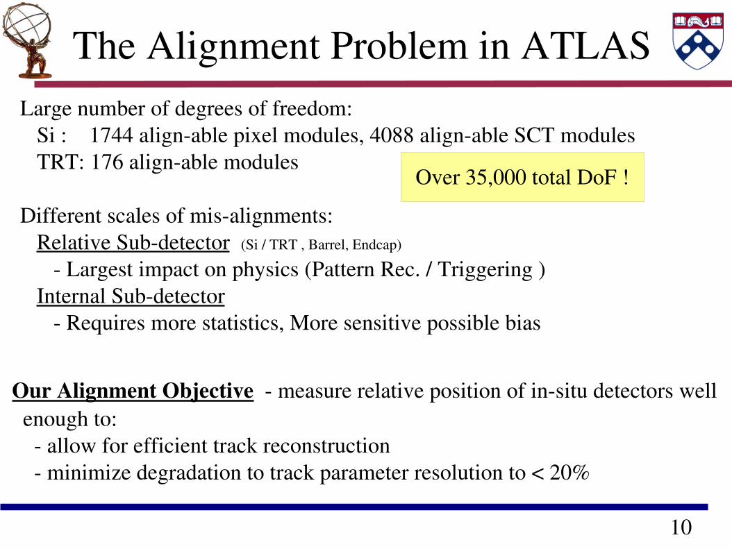
The Alignment Problem in ATLAS
Our Alignment Objective measure relative position of insitu detectors well enough to: allow for efficient track reconstruction minimize degradation to track parameter resolution to < 20%
Large number of degrees of freedom: Si : 1744 alignable pixel modules, 4088 alignable SCT modules TRT: 176 alignable modules
Different scales of misalignments: Relative Subdetector (Si / TRT , Barrel, Endcap)
Largest impact on physics (Pattern Rec. / Triggering ) Internal Subdetector Requires more statistics, More sensitive possible bias
Over 35,000 total DoF !
11
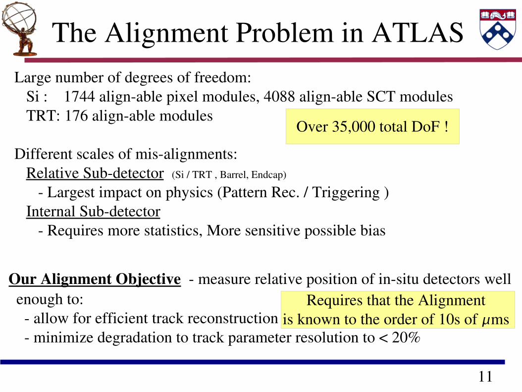
The Alignment Problem in ATLAS
Our Alignment Objective measure relative position of insitu detectors well enough to: allow for efficient track reconstruction minimize degradation to track parameter resolution to < 20%
Large number of degrees of freedom: Si : 1744 alignable pixel modules, 4088 alignable SCT modules TRT: 176 alignable modules
Different scales of misalignments: Relative Subdetector (Si / TRT , Barrel, Endcap)
Largest impact on physics (Pattern Rec. / Triggering ) Internal Subdetector Requires more statistics, More sensitive possible bias
Over 35,000 total DoF !
Requires that the Alignment is known to the order of 10s of ms
12
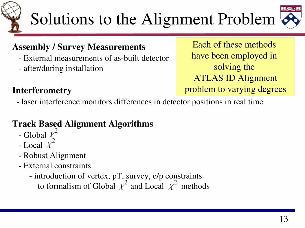
Solutions to the Alignment ProblemAssembly / Survey Measurements External measurements of asbuilt detector after/during installation
Interferometry laser interference monitors differences in detector positions in real time
Track Based Alignment Algorithms Global Local Robust Alignment External constraints introduction of vertex, pT, survey, e/p constraints to formalism of Global and Local methods
13
Solutions to the Alignment ProblemAssembly / Survey Measurements External measurements of asbuilt detector after/during installation
Interferometry laser interference monitors differences in detector positions in real time
Track Based Alignment Algorithms Global Local Robust Alignment External constraints introduction of vertex, pT, survey, e/p constraints to formalism of Global and Local methods
Each of these methods have been employed in
solving the ATLAS ID Alignment
problem to varying degrees
14
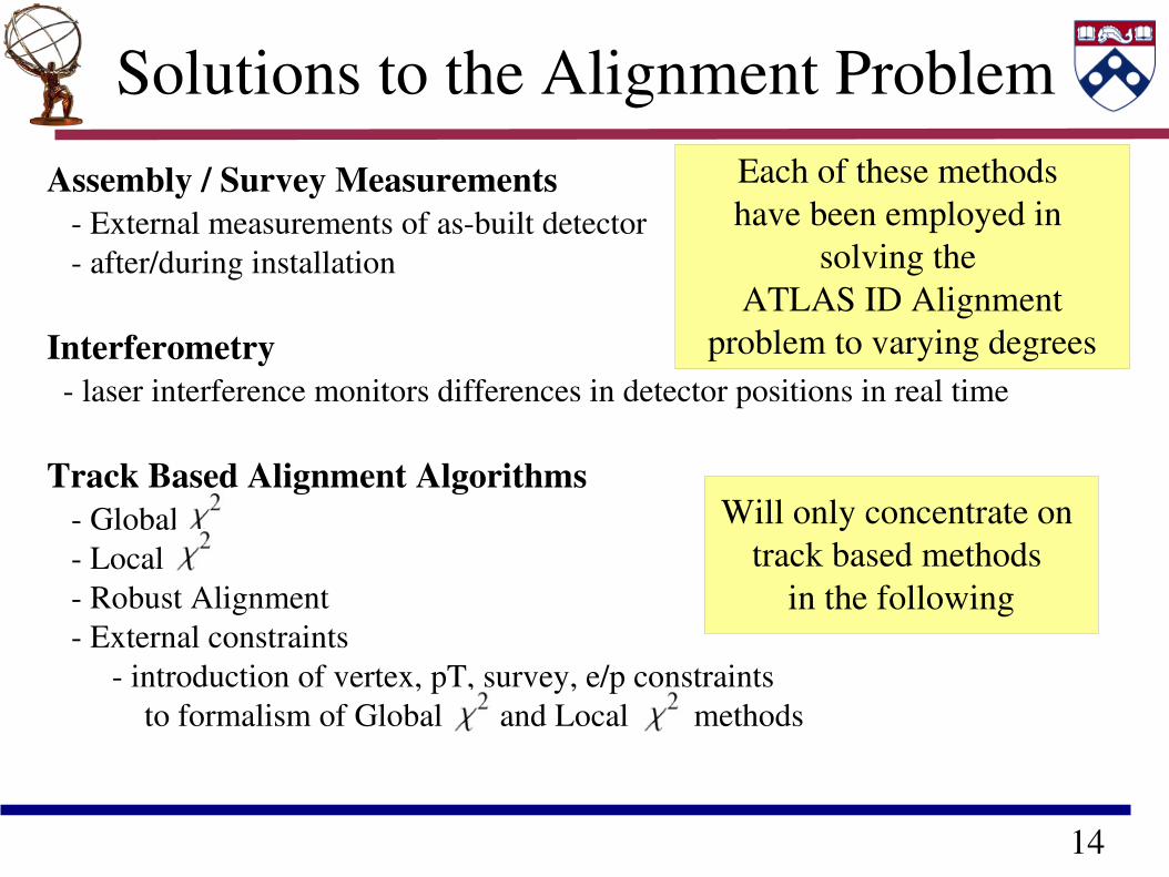
Solutions to the Alignment ProblemAssembly / Survey Measurements External measurements of asbuilt detector after/during installation
Interferometry laser interference monitors differences in detector positions in real time
Track Based Alignment Algorithms Global Local Robust Alignment External constraints introduction of vertex, pT, survey, e/p constraints to formalism of Global and Local methods
Each of these methods have been employed in
solving the ATLAS ID Alignment
problem to varying degrees
Will only concentrate on track based methods
in the following
15
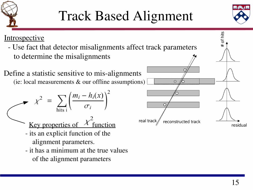
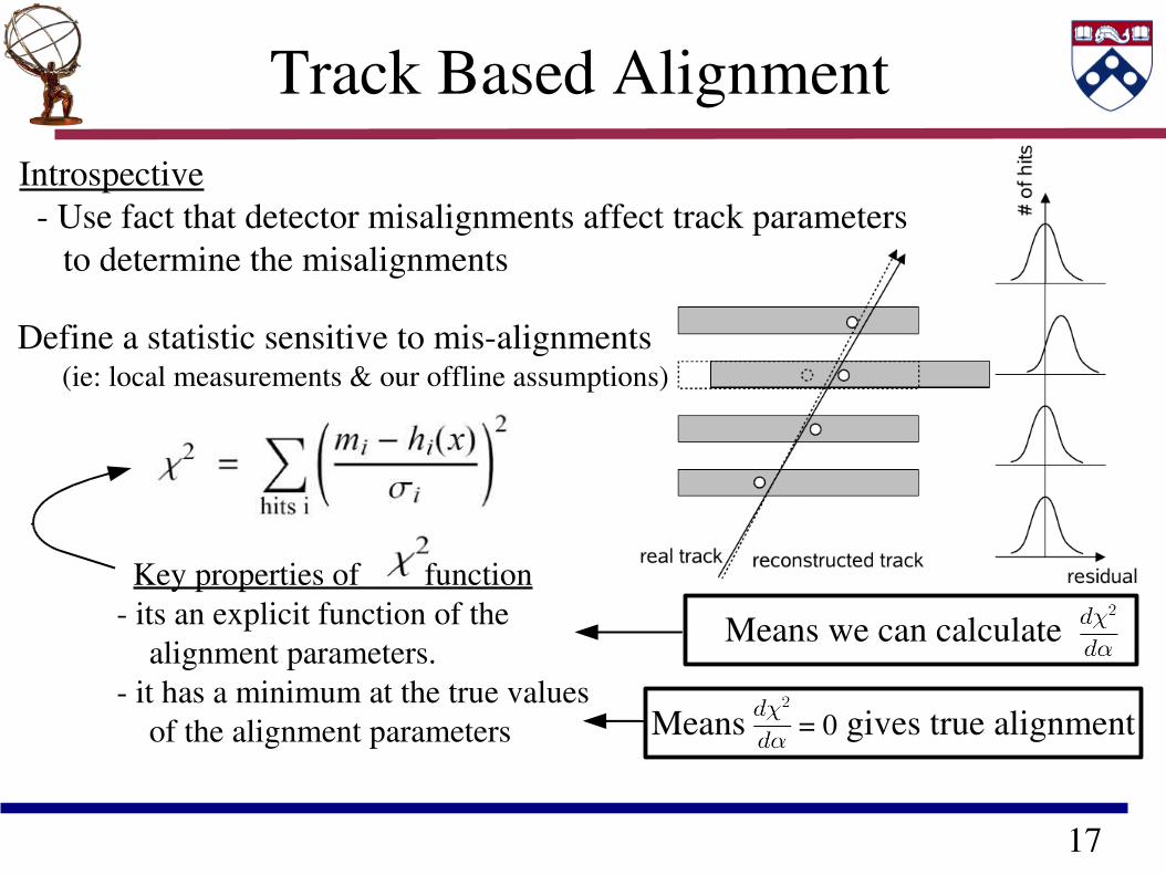
Track Based AlignmentIntrospective Use fact that detector misalignments affect track parameters to determine the misalignments
Define a statistic sensitive to misalignments (ie: local measurements & our offline assumptions)
Key properties of function its an explicit function of the alignment parameters. it has a minimum at the true values of the alignment parameters
16
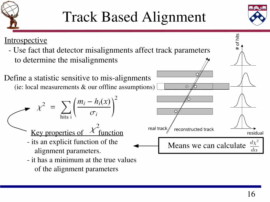
Track Based AlignmentIntrospective Use fact that detector misalignments affect track parameters to determine the misalignments
Define a statistic sensitive to misalignments (ie: local measurements & our offline assumptions)
Key properties of function its an explicit function of the alignment parameters. it has a minimum at the true values of the alignment parameters
Means we can calculate
17
Track Based AlignmentIntrospective Use fact that detector misalignments affect track parameters to determine the misalignments
Define a statistic sensitive to misalignments (ie: local measurements & our offline assumptions)
Key properties of function its an explicit function of the alignment parameters. it has a minimum at the true values of the alignment parameters
Means we can calculate
Means = 0 gives true alignment
18
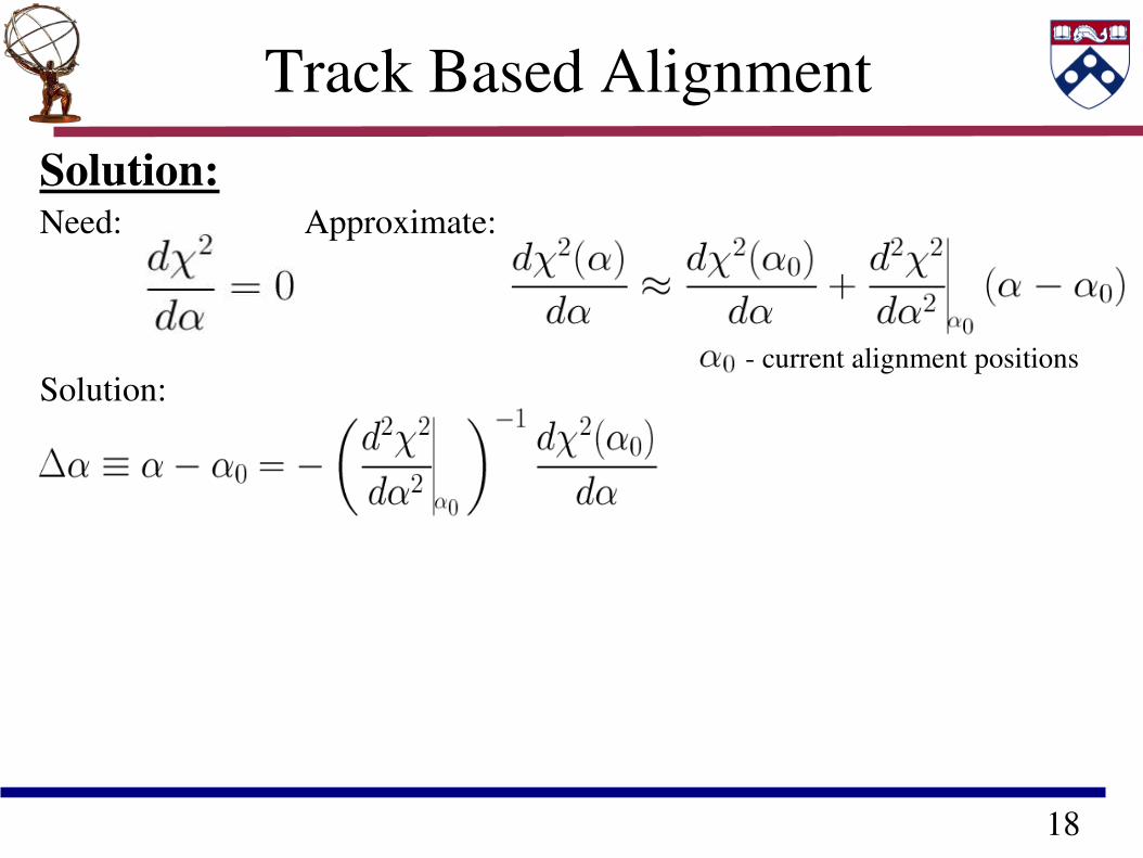
Track Based AlignmentSolution:Need: Approximate:
Solution: current alignment positions
19
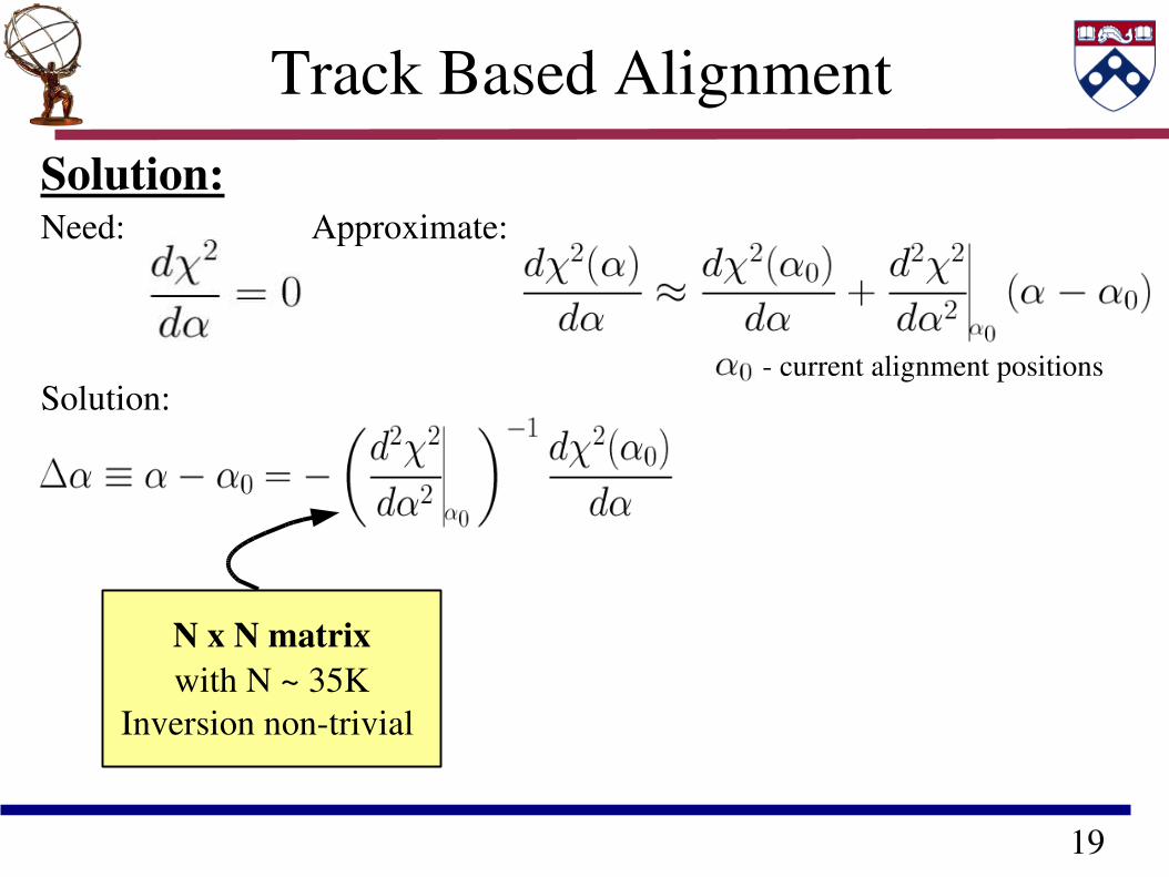
Track Based AlignmentSolution:Need: Approximate:
Solution: current alignment positions
N x N matrixwith N ~ 35K
Inversion nontrivial
20
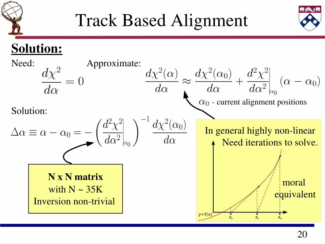
Track Based AlignmentSolution:Need: Approximate:
Solution: current alignment positions
In general highly nonlinear Need iterations to solve.
moral equivalent
N x N matrixwith N ~ 35K
Inversion nontrivial
21
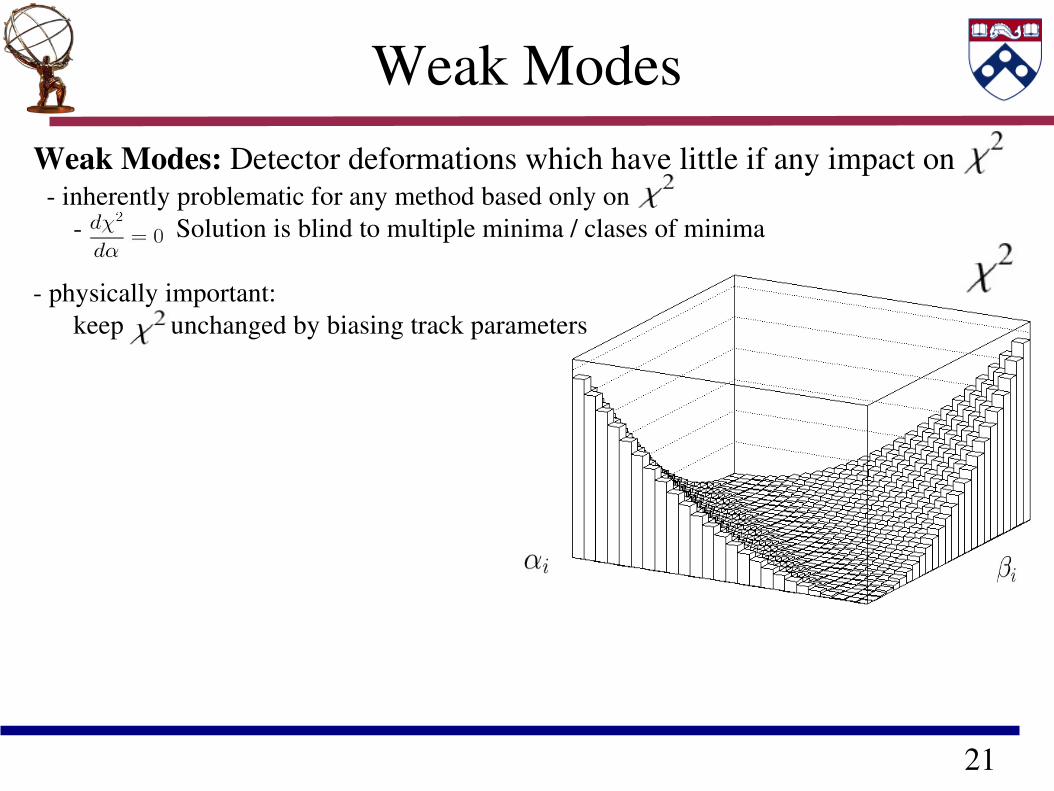
Weak ModesWeak Modes: Detector deformations which have little if any impact on inherently problematic for any method based only on Solution is blind to multiple minima / clases of minima physically important: keep unchanged by biasing track parameters
22
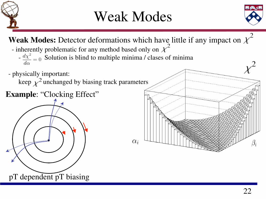
Weak ModesWeak Modes: Detector deformations which have little if any impact on inherently problematic for any method based only on Solution is blind to multiple minima / clases of minima physically important: keep unchanged by biasing track parameters
Example: “Clocking Effect”
pT dependent pT biasing
23
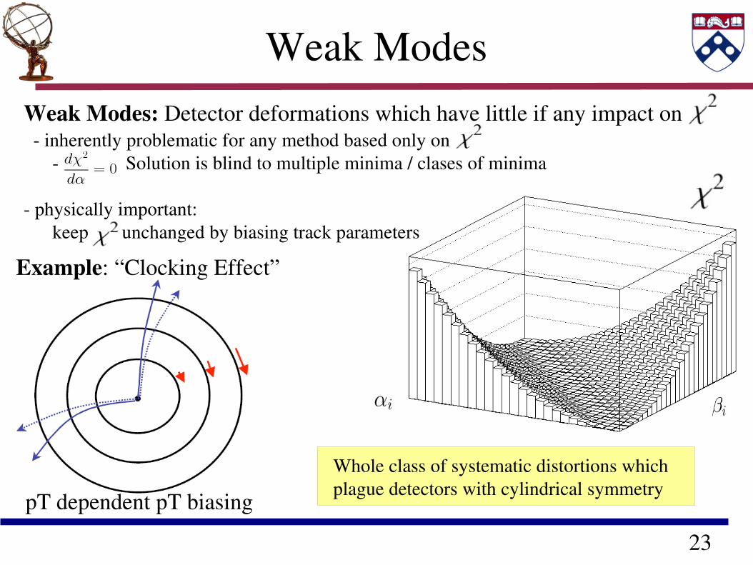
Weak ModesWeak Modes: Detector deformations which have little if any impact on inherently problematic for any method based only on Solution is blind to multiple minima / clases of minima physically important: keep unchanged by biasing track parameters
Example: “Clocking Effect”
pT dependent pT biasing
Whole class of systematic distortions which plague detectors with cylindrical symmetry
24
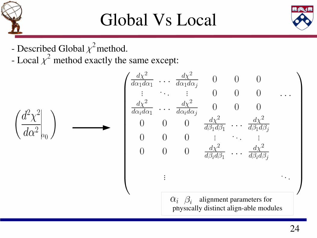
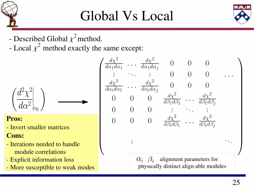
Global Vs Local Described Global method. Local method exactly the same except:
, alignment parameters for physically distinct alignable modules
25
Global Vs Local Described Global method. Local method exactly the same except:
, alignment parameters for physically distinct alignable modules
Pros: Invert smaller matricesCons: Iterations needed to handle module correlations Explicit information loss More susceptible to weak modes
26
Dealing with
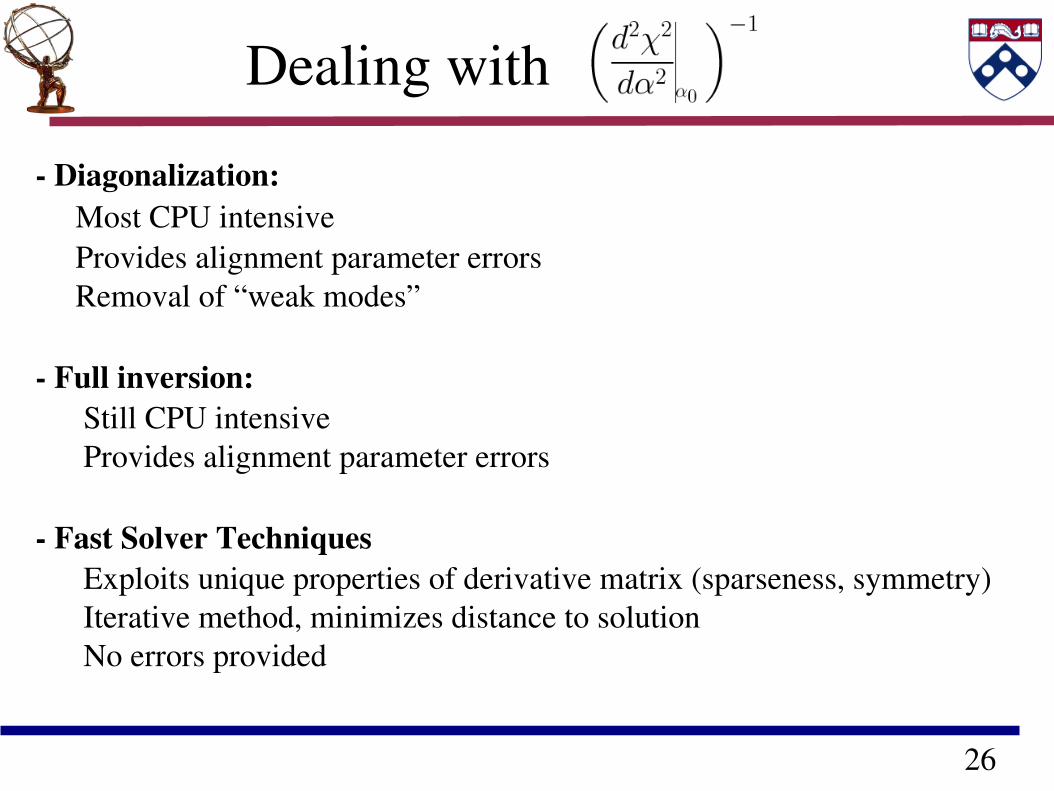
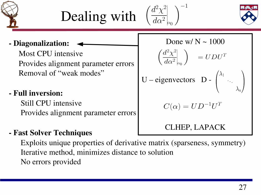
Diagonalization: Most CPU intensive Provides alignment parameter errors Removal of “weak modes”
Full inversion: Still CPU intensive Provides alignment parameter errors
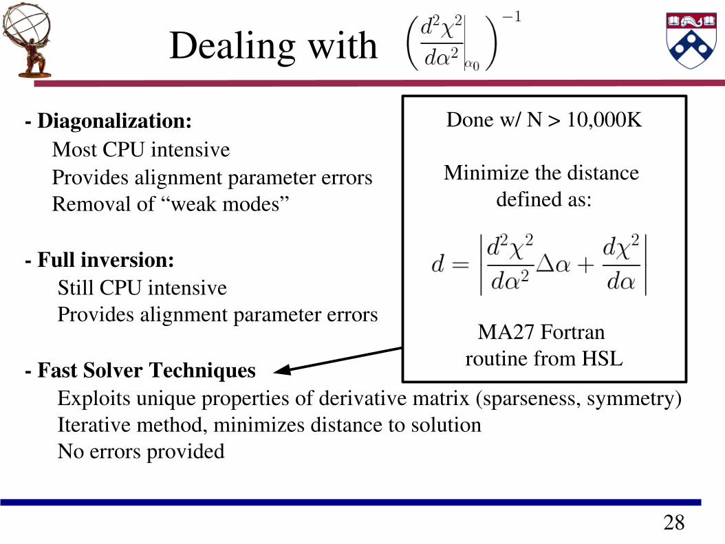
Fast Solver Techniques Exploits unique properties of derivative matrix (sparseness, symmetry) Iterative method, minimizes distance to solution No errors provided
27
Dealing with
Diagonalization: Most CPU intensive Provides alignment parameter errors Removal of “weak modes”
Full inversion: Still CPU intensive Provides alignment parameter errors
Fast Solver Techniques Exploits unique properties of derivative matrix (sparseness, symmetry) Iterative method, minimizes distance to solution No errors provided
Done w/ N ~ 1000
U – eigenvectors D
CLHEP, LAPACK
28
Dealing with
Diagonalization: Most CPU intensive Provides alignment parameter errors Removal of “weak modes”
Full inversion: Still CPU intensive Provides alignment parameter errors
Fast Solver Techniques Exploits unique properties of derivative matrix (sparseness, symmetry) Iterative method, minimizes distance to solution No errors provided
Done w/ N > 10,000K
Minimize the distance defined as:
MA27 Fortran routine from HSL
29
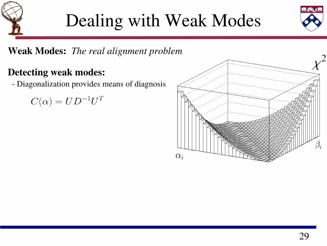
Dealing with Weak Modes
Weak Modes: The real alignment problem
Detecting weak modes: Diagonalization provides means of diagnosis
30
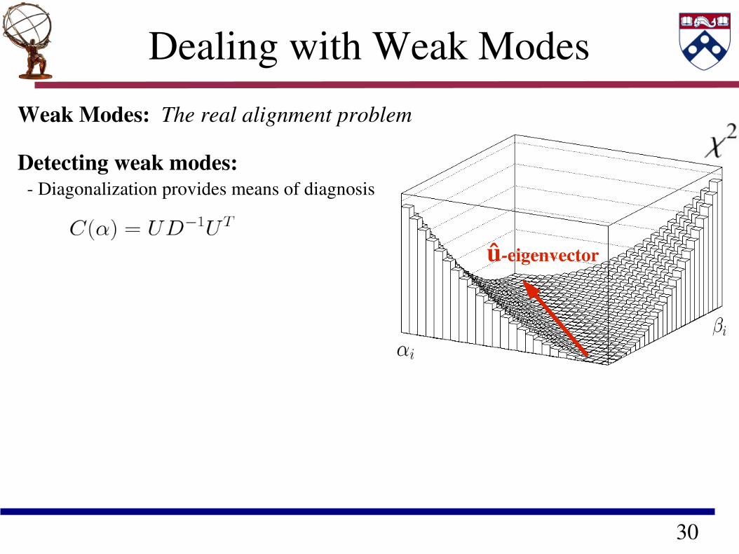
Dealing with Weak Modes
Weak Modes: The real alignment problem
Detecting weak modes: Diagonalization provides means of diagnosis
ûeigenvector
31
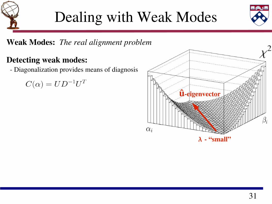
Dealing with Weak Modes
Weak Modes: The real alignment problem
Detecting weak modes: Diagonalization provides means of diagnosis
ûeigenvector
“small”
32
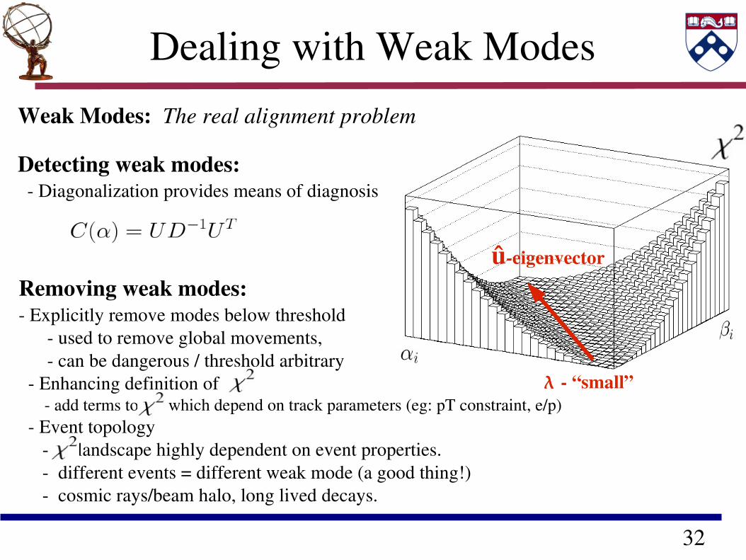
Dealing with Weak Modes
Weak Modes: The real alignment problem
Detecting weak modes: Diagonalization provides means of diagnosis
ûeigenvector
“small”
Removing weak modes: Explicitly remove modes below threshold used to remove global movements, can be dangerous / threshold arbitrary Enhancing definition of add terms to which depend on track parameters (eg: pT constraint, e/p) Event topology landscape highly dependent on event properties. different events = different weak mode (a good thing!) cosmic rays/beam halo, long lived decays.

33
And now, some results.
“Personally, I liked the university. They gave us money and facilities, we didn't have to produce anything. You've never been out of college. You don't know what it's like out there. I've worked in the private sector. They expect results.” Dr. Ray Stanz
34
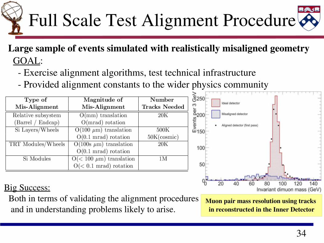
Full Scale Test Alignment ProcedureLarge sample of events simulated with realistically misaligned geometry GOAL: Exercise alignment algorithms, test technical infrastructure Provided alignment constants to the wider physics community
Big Success: Both in terms of validating the alignment procedures and in understanding problems likely to arise.
Muon pair mass resolution using tracks in reconstructed in the Inner Detector
35
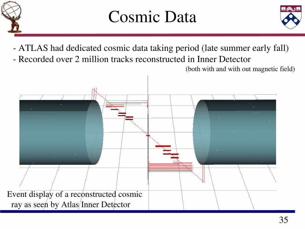
Cosmic Data
ATLAS had dedicated cosmic data taking period (late summer early fall) Recorded over 2 million tracks reconstructed in Inner Detector (both with and with out magnetic field)
Event display of a reconstructed cosmic ray as seen by Atlas Inner Detector
36
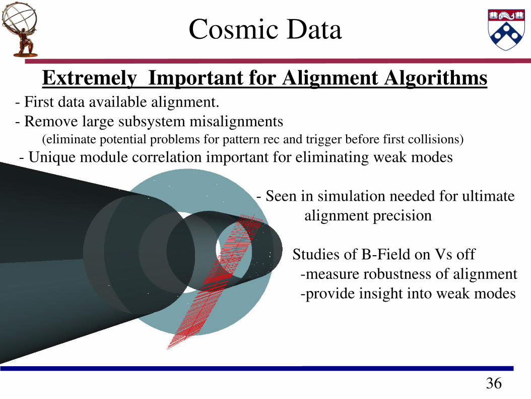
Extremely Important for Alignment Algorithms First data available alignment. Remove large subsystem misalignments (eliminate potential problems for pattern rec and trigger before first collisions) Unique module correlation important for eliminating weak modes Seen in simulation needed for ultimate alignment precision Studies of BField on Vs off measure robustness of alignment provide insight into weak modes
Cosmic Data
37
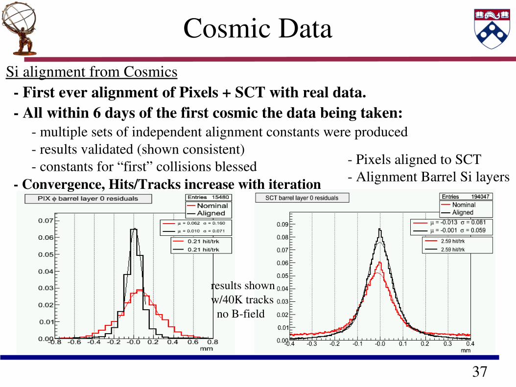
Cosmic DataSi alignment from Cosmics
Pixels aligned to SCT Alignment Barrel Si layers
First ever alignment of Pixels + SCT with real data. All within 6 days of the first cosmic the data being taken: multiple sets of independent alignment constants were produced results validated (shown consistent) constants for “first” collisions blessed Convergence, Hits/Tracks increase with iteration
results shownw/40K tracks no Bfield
38
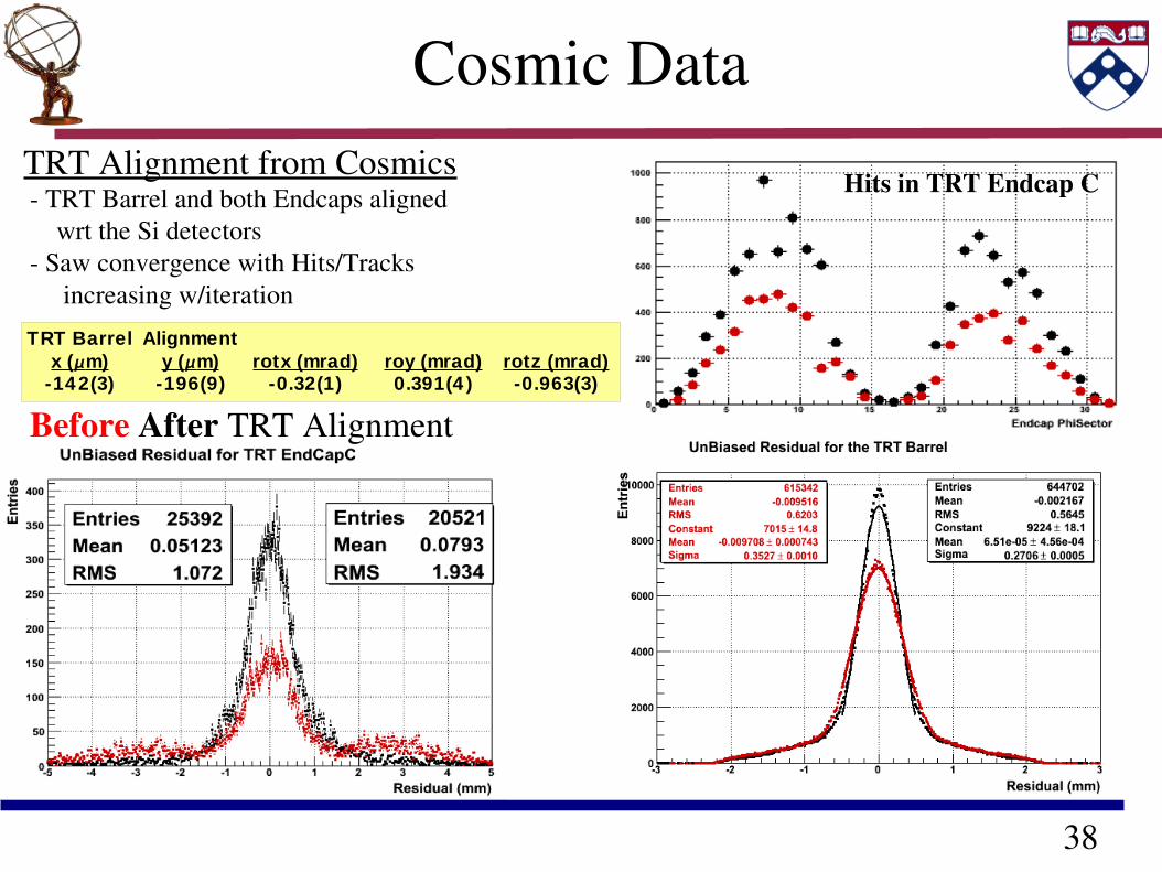
Cosmic DataTRT Alignment from Cosmics TRT Barrel and both Endcaps aligned wrt the Si detectors Saw convergence with Hits/Tracks increasing w/iteration
Before After TRT Alignment
Hits in TRT Endcap C
TRT Barrel Alignment
-14 2(3) -196(9) -0.32(1) 0.391(4 ) -0.963(3)x (m) y (m) rotx (mrad) roy (mrad) rotz (mrad)
39
Conclusions Overall scale and ultimate precision of ATLAS Inner Detector poses a challenging problem in terms of understanding the detector. Alignment crucial to reach full physics potential / detector performance Track based method provides means of addressing alignment problem Implemented in ATLAS framework Thorough and Stringent tests of software allowed for capitalization on early cosmic data. Cosmics have and continue to provide a starting point and guide the way to the ultimate alignment Poised meeting the alignment challenge at first collisions

40
Bonus.
41
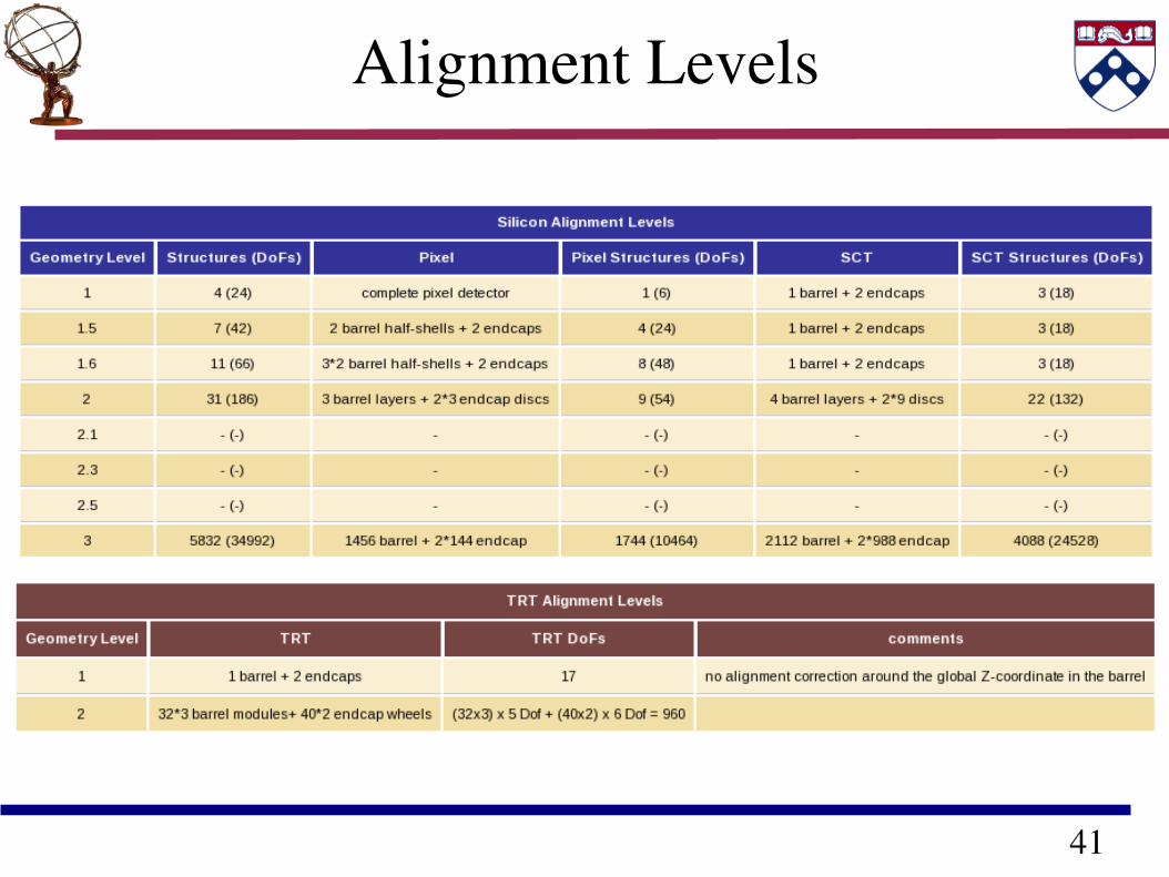
Alignment Levels
42
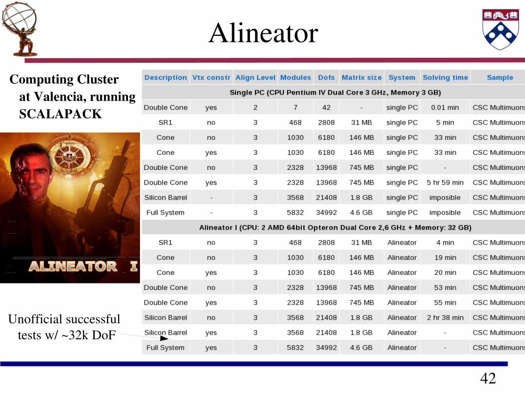
Alineator
Unofficial successful tests w/ ~32k DoF
Computing Cluster at Valencia, running SCALAPACK
43
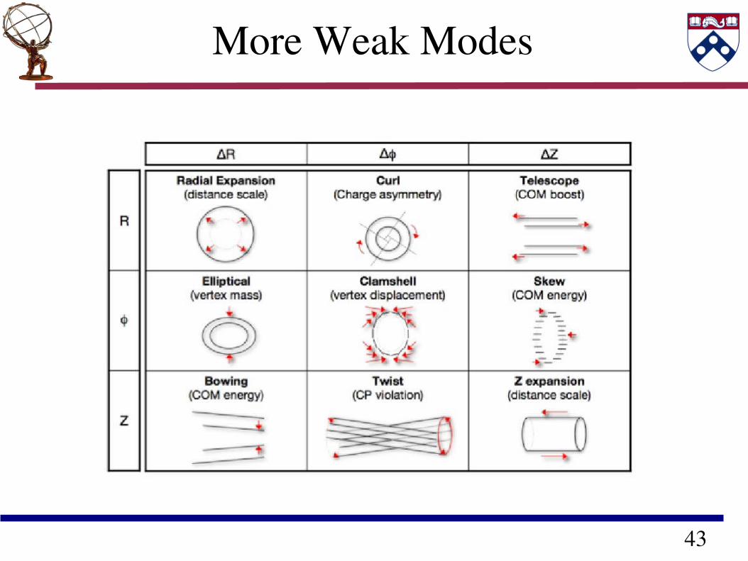
More Weak Modes


![arXiv:1202.1415v4 [hep-ex] 23 Mar 2012 · benefits from recent significant improvements in the alignment of the inner detector and the muon spectrometer. 2. The ATLAS Detector The](https://img.pdfslide.us/doc/110x75/601cef88c50cac6a4b44f62c/arxiv12021415v4-hep-ex-23-mar-2012-beneits-from-recent-signiicant-improvements.jpg)