Embed Size (px)
Citation preview
KNKT/07.01/08.01.36
NATIONAL TRANSPORTATION SAFETY COMMITTEE MINISTRY OF TRANSPORTATION REPUBLIC OF INDONESIA 2008
BOEING 737–4Q8
PK–KKW
MAKASSAR STRAIT, SULAWESIREPUBLIC OF INDONESIA
1 JANUARY 2007
NNAATTIIOONNAALL TTRRAANNSSPPOORRTTAATTIIOONN SSAAFFEETTYY CCOOMMMMIITTTTEEEE
Aircraft Accident Investigation Report


ISBN: 978–979–16958–1–7
When the NTSC makes recommendations as a result of its investigations or research, safety is its primary consideration.
However, the NTSC fully recognizes that the implementation of recommendations arising from its investigations will in some cases incur a cost to the industry.
Readers should note that the information in NTSC reports and recommendations is provided to promote aviation safety. In no case is it intended to imply blame or liability.
This report was produced by the National Transportation Safety Committee (NTSC), Karya Building 7th Floor Ministry of Transportation, Jalan Medan Merdeka Barat No. 8 JKT 10110, Indonesia.
The report is based upon the investigation carried out by the NTSC in accordance with Annex 13 to the Convention on International Civil Aviation, Indonesian Law (UU No.15/1992), and Government Regulation (PP No. 3/2001).
Readers are advised that the NTSC investigates for the sole purpose of enhancing aviation safety. Consequently, NTSC reports are confined to matters of safety significance and may be misleading if used for any other purpose.
As NTSC believes that safety information is of greatest value if it is passed on for the use of others, readers are encouraged to copy or reprint for further distribution, acknowledging NTSC as the source.


i
TABLE OF CONTENTS
TABLE OF CONTENTS ......................................................................................................... i
TABLE OF FIGURES ........................................................................................................... iv
LIST OF APPENDIXES......................................................................................................... v
LIST OF FIGURES APPENDIX A ......................................................................................vi
GLOSSARY OF ABBREVIATIONS ...................................................................................vii
SYNOPSIS ............................................................................................................................... 1
1. FACTUAL INFORMATION ..................................................................................... 5
1.1 History of the Flight ......................................................................................................5
1.2 Injuries to Persons..........................................................................................................9
1.3 Damage to aircraft .........................................................................................................9
1.4 Other damage.................................................................................................................9
1.5 Personnel information ...................................................................................................9
1.5.1 Cockpit crew..........................................................................................................9
1.5.2 Pilot in command ...................................................................................................9
1.5.3 Copilot .................................................................................................................11
1.6 Aircraft Information ....................................................................................................13
1.6.1 Aircraft Data ........................................................................................................13
1.6.2 Engine Data .........................................................................................................13
1.6.3 Underwater Locator Beacon ................................................................................14
1.6.4 Weight and Balance.............................................................................................14
1.6.5 Maintenance.........................................................................................................14
1.7 Meteorological Information.........................................................................................15
1.8 Aids to Navigation .......................................................................................................19
1.9 Communications ..........................................................................................................19
1.10 Aerodrome Information ...............................................................................................19
1.11 Flight Recorders...........................................................................................................19
1.11.1 Digital Flight Data Recorder................................................................................19
1.11.2 Cockpit Voice Recorder ......................................................................................24
1.11.3 Notable facts from the CVR................................................................................25
1.12 Wreckage and impact information...............................................................................29
1.13 Medical and Pathological Information .........................................................................29
1.14 Fire...............................................................................................................................29
1.15 Search and survival aspects..........................................................................................29
ii
1.15.1 Search .................................................................................................................. 29
1.15.2 Survival................................................................................................................ 33
1.16 Test and Research ........................................................................................................ 34
1.17 Organizational and Management Information.............................................................. 35
1.17.1 Adam SkyConnection Airlines (AdamAir)......................................................... 35
1.17.2 Directorate General Civil Aviation (DGCA) surveillance of AdamAir flight operations and airworthiness.............................................................................. 36
1.18 Additional Information ................................................................................................ 37
1.18.1 Standby Attitude Indicator – Erection to false vertical ....................................... 37
1.18.2 IRS Transfer Switch, Figure 11, item 1 .............................................................. 38
1.18.3 Electronic Flight Instrument (EFI) Transfer Switch, Figure 11, Item 2 ............. 39
1.18.4 Mode Selector Unit (MSU), Figure 11, item 3 ................................................... 39
1.18.5 Autopilot Disengage............................................................................................ 40
1.18.6 Navigation System Description........................................................................... 41
1.18.7 Inertial System..................................................................................................... 41
1.18.8 IRS Alignment..................................................................................................... 42
1.18.9 Loss of Alignment............................................................................................... 42
1.18.10 Navigation System Assessment ― IRUs ............................................................ 42
1.18.11 Flight Management System................................................................................. 43
1.18.12 Aircraft on Ground .............................................................................................. 43
1.18.13 Aircraft - Airborne .............................................................................................. 44
1.18.14 Pilots’ Flight Track Information.......................................................................... 45
1.18.15 General information on Makassar Advanced Air Traffic Services (MAATS) Air traffic control related issues ............................................................................... 46
1.18.16 Radar ................................................................................................................... 46
1.18.17 Human Factors .................................................................................................... 48
2. ANALYSIS................................................................................................................. 49
3. CONCLUSIONS........................................................................................................ 55
3.1 Findings....................................................................................................................... 55
3.1.1 Operations related issues ..................................................................................... 55
3.1.2 Maintenance engineering related issues; AdamAir............................................. 56
3.1.3 Maintenance engineering related issues; Directorate General Civil Aviation .... 57
3.1.4 Other findings...................................................................................................... 57
3.2 Causes.......................................................................................................................... 57
3.2.1 Other Causal Factors ........................................................................................... 58
iii
4. SAFETY ACTION .................................................................................................... 59
4.1 Directorate General Civil Aviation .............................................................................59
4.2 AdamAir maintenance.................................................................................................60
4.3 AdamAir operations ....................................................................................................60
4.4 Angkasa Pura I ............................................................................................................62
5. SAFETY RECOMMENDATIONS ......................................................................... 65
5.1 Recommendation to Directorate General Civil Aviation (DGCA) .............................65
5.2 Recommendation to Directorate General Civil Aviation (DGCA) .............................65
5.3 Recommendation to Directorate General Civil Aviation (DGCA) .............................66
5.4 Recommendation to the Directorate General Civil Aviation (DGCA) and Adam SkyConnection Airline ................................................................................................66
5.5 Recommendation to Directorate General Civil Aviation (DGCA) .............................67
5.6 Recommendation to Adam Air and other Indonesian airlines operating Boeing 737 aircraft .........................................................................................................................67
5.7 Recommendation to Directorate General Civil Aviation (DGCA) .............................68
5.8 Recommendation to Adam SkyConnection Airline ....................................................68
5.9 Recommendation to Ministry of Transportation of the Republic of Indonesia. .........68
5.10 Recommendation to Angkasa Pura I. ..........................................................................68
5.11 Recommendation to AdamAir.....................................................................................69
6. APPENDICES ........................................................................................................... 71
iv
TABLE OF FIGURES
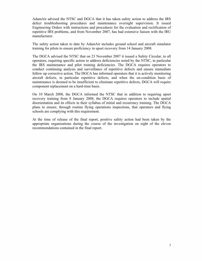
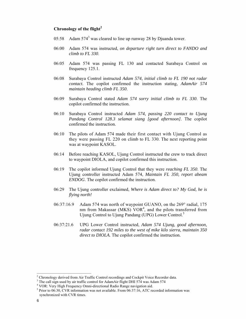
Figure 1 : PK-KKW, AdamAir Boeing 737-4Q8 at Jakarta on 3 June 2006 ..................... 5
Figure 2: Route orientation chart showing route W32 and waypoints and reporting points ................................................................................................................. 7
Figure 3: Convective activity weather map of 07:00 UTC showing location of PK-KKW near severe weather cell at 06:54 UTC ........................................... 16
Figure 4: Satellite image of clouds over Indonesia 1 January 2007 at 06:00 UTC ......... 17
Figure 5: Satellite image of clouds over Indonesia 1 January 2007 at 12:00 UTC ......... 18
Figure 6: Fixed time forecast chart for ICAO area E Significant Weather from FL250 to FL 630. Valid 1200 UTC on 1 January 2007 showing forecast isolated embedded cumulonimbus cloud in the area of the flight. ................................ 18
Figure 7: Calculated rate of descent ................................................................................ 23
Figure 8: DFDR plot showing last 130 seconds of recorded data ................................... 28
Figure 9: Diagram of typical underwater detection equipment ....................................... 30
Figure 10: Color sonar schematic search diagram............................................................. 30
Figure 11: The multi-beam scanning ................................................................................. 31
Figure 12: Outboard section of right elevator.................................................................... 32
Figure 13: Recovery of flight recorders............................................................................. 33
Figure 14 : Boeing 737-400 overhead instrument panel..................................................... 38
Figure 15: Combination local track and system track . ..................................................... 47
v
LIST OF APPENDIXES
Appendix A: Aircraft parts found floating in the sea between Majene and Barru..................71
Appendix B: Quick Reference Handbook Chapter 11, page 11.5 from myboeingfleet.com..75
Appendix C: Quick Reference Handbook Chapter 11, pages 11.4 and 11.5 used by AdamAir pilots for training reference................................................................76
Appendix D: Human Factors...................................................................................................78
Appendix E: IRS Display Unit and IRS Mode Selector Unit .................................................84
vi
LIST OF FIGURES APPENDIX A
Figure A1 : Map of parts found floating in the sea between Pare-pare and Baru, South Sulawesi .............................................................................................................71
Figure A2 : Part of right elevator showing upper surface (Red arrows point to hinges). Found floating in the sea close to Sulawesi island (between Pare-pare and Baru, South Sulawesi) Makassar Strait ......................................................71
Figure A3 : Part of Left Elevator showing upper surface. Found floating in the sea off the coast near Pare-Pare ..............................................................................72
Figure A4 : Part of left elevator showing lower surface. Found floating in the sea off the coast near Pare-Pare ...................................................................................72
Figure A5 : Part of elevator tab. Found floating in the sea off the coast near Pare-Pare 73
Figure A6 : Part of elevator tab. Found floating in the sea around Pare-pare ......................73
Figure A7 : Flight spoiler (showing lower surface) found floating in the sea off the coast of Pare-pare ..............................................................................................73
Figure A8 : Flight spoiler as in figure B7 (showing lower surface)......................................74
Figure A9 : Seatback tray tables and seat cushions...............................................................74
vii
GLOSSARY OF ABBREVIATIONS
AD : Airworthiness Directive AFM : Airplane Flight Manual AGL : Above Ground Level ALAR Approach-and-Landing Accident Reduction AMSL : Above Mean Sea Level AOC : Air Operator Certificate ATC : Air Traffic Control ATPL : Air Transport Pilot License ATS : Air Traffic Service ATSB : Australian Transport Safety Bureau Avsec : Aviation Security BMG : Badan Meterologi dan Geofisika BOM : Basic Operation Manual CAMP : Continuous Airworthiness Maintenance Program CASO : Civil Aviation Safety Officer CASR : Civil Aviation Safety Regulation CPL : Commercial Pilot License COM : Company Operation Manual CRM : Cockpit Recourses Management CSN : Cycles Since New CVR : Cockpit Voice Recorder DFDAU : Digital Flight Data Acquisition Unit DGCA : Directorate General Civil Aviation DME : Distance Measuring Equipment EEPROM : Electrically Erasable Programmable Read Only Memory EFIS : Electronic Flight Instrument System EGT : Exhaust Gas Temperature EIS : Engine Indicating System FL : Flight Level F/O : First officer or Copilot FDR : Flight Data Recorder FOQA : Flight Operation Quality Assurance GPWS : Ground Proximity Warning System Hrs : Hours
viii
ICAO International Civil Aviation Organization IFR : Instrument Flight Rules IIC : Investigator in Charge ILS : Instrument Landing System Kg : Kilogram(s) Km : Kilometer(s) Kts : Knots (nm/hours) Mm : Millimeter(s) MTOW : Maximum Take-off Weight Nm NTSB
: Nautical mile(s) National Transportation Safety Board (USA)
KNKT / NTSC : Komite Nasional Keselamatan Transportasi / National Transportation Safety Committee
°C : Degrees Celsius PIC : Pilot in Command QFE : Height above airport elevation (or runway threshold
elevation) based on local station pressure QNH : Altitude above mean sea level based on local station
pressure RESA : Runway End Safety Area RPM : Revolution Per Minute ROV : Remotely Operated Vehicle SCT : Scattered S/N : Serial Number SSCVR : Solid State Cockpit Voice Recorder SSFDR : Solid State Flight Data Recorder TS/RA : Thunderstorm and rain TAF : Terminal Aerodrome Forecast TPL : Towed Pinger Locator TSN : Time Since New TT/TD : Ambient Temperature/Dew Point TTIS : Total Time in Service UTC : Universal Time Coordinate VFR : Visual Flight Rules VMC : Visual Meteorological Conditions
1
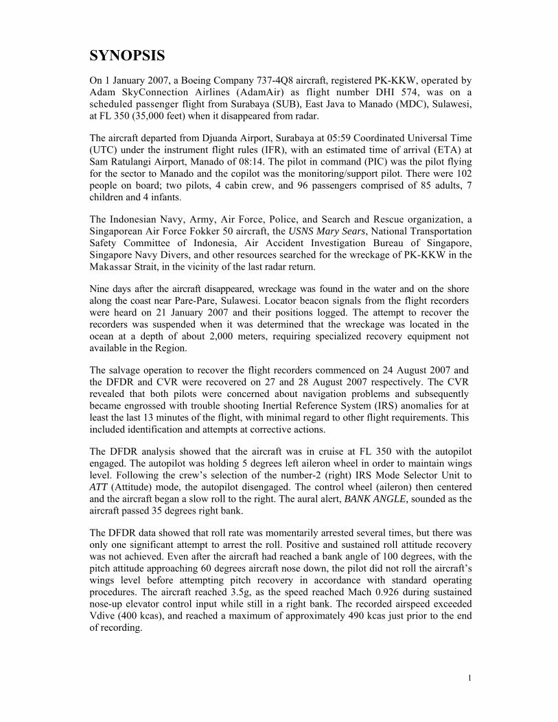
SYNOPSIS On 1 January 2007, a Boeing Company 737-4Q8 aircraft, registered PK-KKW, operated by Adam SkyConnection Airlines (AdamAir) as flight number DHI 574, was on a scheduled passenger flight from Surabaya (SUB), East Java to Manado (MDC), Sulawesi, at FL 350 (35,000 feet) when it disappeared from radar.
The aircraft departed from Djuanda Airport, Surabaya at 05:59 Coordinated Universal Time (UTC) under the instrument flight rules (IFR), with an estimated time of arrival (ETA) at Sam Ratulangi Airport, Manado of 08:14. The pilot in command (PIC) was the pilot flying for the sector to Manado and the copilot was the monitoring/support pilot. There were 102 people on board; two pilots, 4 cabin crew, and 96 passengers comprised of 85 adults, 7 children and 4 infants.
The Indonesian Navy, Army, Air Force, Police, and Search and Rescue organization, a Singaporean Air Force Fokker 50 aircraft, the USNS Mary Sears, National Transportation Safety Committee of Indonesia, Air Accident Investigation Bureau of Singapore, Singapore Navy Divers, and other resources searched for the wreckage of PK-KKW in the Makassar Strait, in the vicinity of the last radar return.
Nine days after the aircraft disappeared, wreckage was found in the water and on the shore along the coast near Pare-Pare, Sulawesi. Locator beacon signals from the flight recorders were heard on 21 January 2007 and their positions logged. The attempt to recover the recorders was suspended when it was determined that the wreckage was located in the ocean at a depth of about 2,000 meters, requiring specialized recovery equipment not available in the Region.
The salvage operation to recover the flight recorders commenced on 24 August 2007 and the DFDR and CVR were recovered on 27 and 28 August 2007 respectively. The CVR revealed that both pilots were concerned about navigation problems and subsequently became engrossed with trouble shooting Inertial Reference System (IRS) anomalies for at least the last 13 minutes of the flight, with minimal regard to other flight requirements. This included identification and attempts at corrective actions.
The DFDR analysis showed that the aircraft was in cruise at FL 350 with the autopilot engaged. The autopilot was holding 5 degrees left aileron wheel in order to maintain wings level. Following the crew’s selection of the number-2 (right) IRS Mode Selector Unit to ATT (Attitude) mode, the autopilot disengaged. The control wheel (aileron) then centered and the aircraft began a slow roll to the right. The aural alert, BANK ANGLE, sounded as the aircraft passed 35 degrees right bank.
The DFDR data showed that roll rate was momentarily arrested several times, but there was only one significant attempt to arrest the roll. Positive and sustained roll attitude recovery was not achieved. Even after the aircraft had reached a bank angle of 100 degrees, with the pitch attitude approaching 60 degrees aircraft nose down, the pilot did not roll the aircraft’s wings level before attempting pitch recovery in accordance with standard operating procedures. The aircraft reached 3.5g, as the speed reached Mach 0.926 during sustained nose-up elevator control input while still in a right bank. The recorded airspeed exceeded Vdive (400 kcas), and reached a maximum of approximately 490 kcas just prior to the end of recording.
2
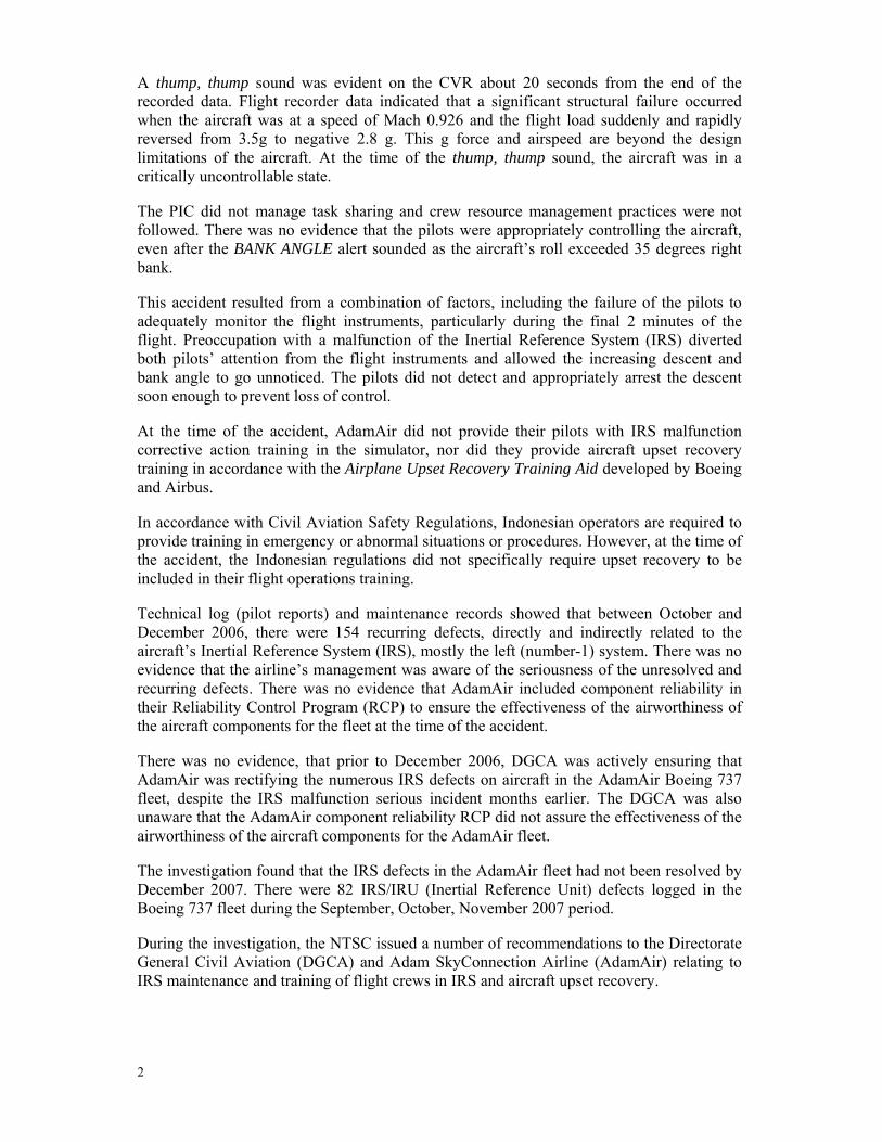
A thump, thump sound was evident on the CVR about 20 seconds from the end of the recorded data. Flight recorder data indicated that a significant structural failure occurred when the aircraft was at a speed of Mach 0.926 and the flight load suddenly and rapidly reversed from 3.5g to negative 2.8 g. This g force and airspeed are beyond the design limitations of the aircraft. At the time of the thump, thump sound, the aircraft was in a critically uncontrollable state.
The PIC did not manage task sharing and crew resource management practices were not followed. There was no evidence that the pilots were appropriately controlling the aircraft, even after the BANK ANGLE alert sounded as the aircraft’s roll exceeded 35 degrees right bank.
This accident resulted from a combination of factors, including the failure of the pilots to adequately monitor the flight instruments, particularly during the final 2 minutes of the flight. Preoccupation with a malfunction of the Inertial Reference System (IRS) diverted both pilots’ attention from the flight instruments and allowed the increasing descent and bank angle to go unnoticed. The pilots did not detect and appropriately arrest the descent soon enough to prevent loss of control.
At the time of the accident, AdamAir did not provide their pilots with IRS malfunction corrective action training in the simulator, nor did they provide aircraft upset recovery training in accordance with the Airplane Upset Recovery Training Aid developed by Boeing and Airbus.
In accordance with Civil Aviation Safety Regulations, Indonesian operators are required to provide training in emergency or abnormal situations or procedures. However, at the time of the accident, the Indonesian regulations did not specifically require upset recovery to be included in their flight operations training.
Technical log (pilot reports) and maintenance records showed that between October and December 2006, there were 154 recurring defects, directly and indirectly related to the aircraft’s Inertial Reference System (IRS), mostly the left (number-1) system. There was no evidence that the airline’s management was aware of the seriousness of the unresolved and recurring defects. There was no evidence that AdamAir included component reliability in their Reliability Control Program (RCP) to ensure the effectiveness of the airworthiness of the aircraft components for the fleet at the time of the accident.
There was no evidence, that prior to December 2006, DGCA was actively ensuring that AdamAir was rectifying the numerous IRS defects on aircraft in the AdamAir Boeing 737 fleet, despite the IRS malfunction serious incident months earlier. The DGCA was also unaware that the AdamAir component reliability RCP did not assure the effectiveness of the airworthiness of the aircraft components for the AdamAir fleet.
The investigation found that the IRS defects in the AdamAir fleet had not been resolved by December 2007. There were 82 IRS/IRU (Inertial Reference Unit) defects logged in the Boeing 737 fleet during the September, October, November 2007 period.
During the investigation, the NTSC issued a number of recommendations to the Directorate General Civil Aviation (DGCA) and Adam SkyConnection Airline (AdamAir) relating to IRS maintenance and training of flight crews in IRS and aircraft upset recovery.
3
AdamAir advised the NTSC and DGCA that it has taken safety action to address the IRS defect troubleshooting procedures and maintenance oversight supervision. It issued Engineering Orders with instructions and procedures for the evaluation and rectification of repetitive IRS problems, and from November 2007, has had extensive liaison with the IRU manufacturer.
The safety action taken to date by AdamAir includes ground school and aircraft simulator training for pilots to ensure proficiency in upset recovery from 14 January 2008.
The DGCA advised the NTSC that on 23 November 2007 it issued a Safety Circular, to all operators, requiring specific action to address deficiencies noted by the NTSC, in particular the IRS maintenance and pilot training deficiencies. The DGCA requires operators to conduct continuing analysis and surveillance of repetitive defects and ensure immediate follow up corrective action. The DGCA has informed operators that it is actively monitoring aircraft defects, in particular repetitive defects, and when the on-condition basis of maintenance is deemed to be insufficient to eliminate repetitive defects, DGCA will require component replacement on a hard-time basis.
On 10 March 2008, the DGCA informed the NTSC that in addition to requiring upset recovery training from 8 January 2008, the DGCA requires operators to include spatial disorientation and its effects in their syllabus of initial and recurrency training. The DGCA plans to ensure, through routine flying operations inspections, that operators and flying schools are complying with this requirement.
At the time of release of the final report, positive safety action had been taken by the appropriate organizations during the course of the investigation on eight of the eleven recommendations contained in the final report.

4
5
1. FACTUAL INFORMATION 1.1 History of the Flight
On 1 January 2007, a Boeing Company 737-4Q8 aircraft, registered PK-KKW, operated by Adam SkyConnection Airlines (AdamAir) as flight number DHI 574, was on a scheduled passenger flight from Surabaya (SUB), East Java to Manado (MDC), Sulawesi, at FL 350 (35,000 feet) when it disappeared from radar.
Figure 1 : PK-KKW, AdamAir Boeing 737-4Q8 at Jakarta on 3 June 2006
The aircraft departed from Djuanda Airport, Surabaya at 05:59 Coordinated Universal Time1 (UTC) under the instrument flight rules (IFR), with an estimated time of arrival (ETA) at Sam Ratulangi Airport, Manado of 08:14. The fuel endurance on departure from Surabaya was 4 hours 30 minutes, and the crew had flight planned for an alternate of Gorontalo (GTO). The pilot in command (PIC) was the pilot flying for the sector to Manado and the copilot was the monitoring/support pilot.
There were 102 people on board; two pilots, 4 cabin crew, and 96 passengers comprised of 85 adults, 7 children and 4 infants.
1 The 24-hour clock in Coordinated Universal Time (UTC) is used in this report to describe the local time as
specific events occurred. Central Indonesia Standard Time (Waktu Indonesia Tengah (WITA)) is UTC +8 hours.
6
Chronology of the flight2
05:58 Adam 5743 was cleared to line up runway 28 by Djuanda tower.
06:00 Adam 574 was instructed, on departure right turn direct to FANDO and climb to FL 330.
06:05 Adam 574 was passing FL 130 and contacted Surabaya Control on frequency 125.1.
06:08 Surabaya Control instructed Adam 574, initial climb to FL 190 not radar contact. The copilot confirmed the instruction stating, AdamAir 574 maintain heading climb FL 350.
06:09 Surabaya Control stated Adam 574 sorry initial climb to FL 330. The copilot confirmed the instruction.
06:10 Surabaya Control instructed Adam 574, passing 220 contact to Ujung Pandang Control 128.3 selamat siang [good afternoon]. The copilot confirmed the instruction.
06:10 The pilots of Adam 574 made their first contact with Ujung Control as they were passing FL 220 on climb to FL 330. The next reporting point was at waypoint KASOL.
06:14 Before reaching KASOL, Ujung Control instructed the crew to track direct to waypoint DIOLA, and copilot confirmed this instruction.
06:19 The copilot informed Ujung Control that they were reaching FL 350. The Ujung controller instructed Adam 574, Maintain FL 350, report abeam ENDOG. The copilot confirmed the instruction.
06:29 The Ujung controller exclaimed, Where is Adam direct to? My God, he is flying north!
06:37:16.9 Adam 574 was north of waypoint GUANO, on the 269° radial, 175 nm from Makassar (MKS) VOR4, and the pilots transferred from Ujung Control to Ujung Pandang (UPG) Lower Control.5
06:37:21.6 UPG Lower Control instructed, Adam 574 Ujung, good afternoon, radar contact 192 miles to the west of mike kilo sierra, maintain 350 direct to DIOLA. The copilot confirmed the instruction.
2 Chronology derived from Air Traffic Control recordings and Cockpit Voice Recorder data. 3 The call sign used by air traffic control for AdamAir flight DHI 574 was Adam 574 4 VOR: Very High Frequency Omni-directional Radio Range navigation aid. 5 Prior to 06:30, CVR information was not available. From 06:37:16, ATC recorded information was
synchronized with CVR times.
7
During the 9 minutes before this communication with UPG Lower, the pilots were discussing their concerns about the weather, and Inertial Reference System (IRS)6 problems, including differences between the two Inertial Reference Units (IRUs); specifically navigation and wind reading discrepancies. A statement at 06:32:40.1, although referring to a problem, was said in the form of a joke. Throughout this time a number of concerns were interspersed with jovial comments.
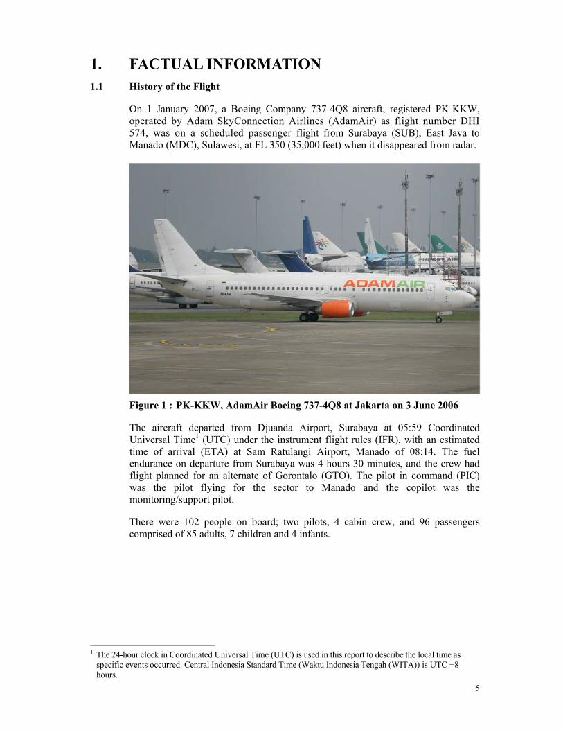
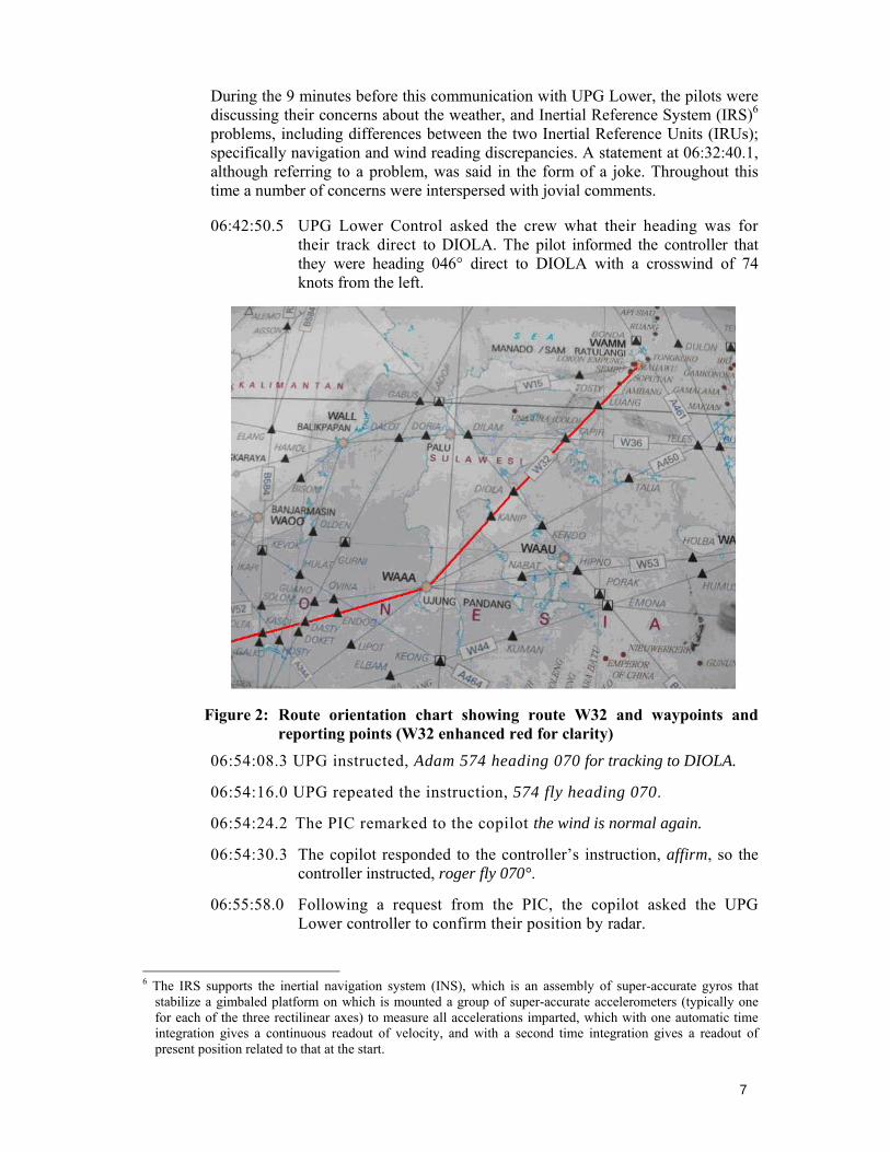
06:42:50.5 UPG Lower Control asked the crew what their heading was for their track direct to DIOLA. The pilot informed the controller that they were heading 046° direct to DIOLA with a crosswind of 74 knots from the left.
Figure 2: Route orientation chart showing route W32 and waypoints and reporting points (W32 enhanced red for clarity)
06:54:08.3 UPG instructed, Adam 574 heading 070 for tracking to DIOLA.
06:54:16.0 UPG repeated the instruction, 574 fly heading 070.
06:54:24.2 The PIC remarked to the copilot the wind is normal again.
06:54:30.3 The copilot responded to the controller’s instruction, affirm, so the controller instructed, roger fly 070°.
06:55:58.0 Following a request from the PIC, the copilot asked the UPG Lower controller to confirm their position by radar.
6 The IRS supports the inertial navigation system (INS), which is an assembly of super-accurate gyros that
stabilize a gimbaled platform on which is mounted a group of super-accurate accelerometers (typically one for each of the three rectilinear axes) to measure all accelerations imparted, which with one automatic time integration gives a continuous readout of velocity, and with a second time integration gives a readout of present position related to that at the start.
8
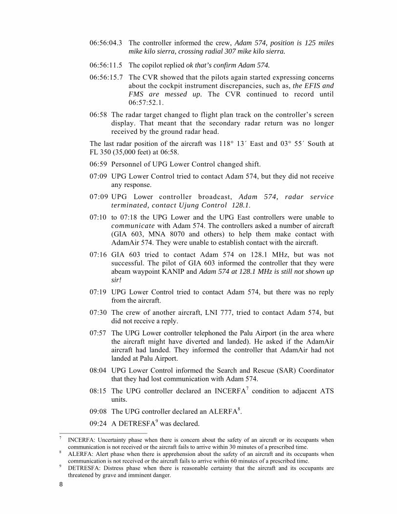
06:56:04.3 The controller informed the crew, Adam 574, position is 125 miles mike kilo sierra, crossing radial 307 mike kilo sierra.
06:56:11.5 The copilot replied ok that’s confirm Adam 574.
06:56:15.7 The CVR showed that the pilots again started expressing concerns about the cockpit instrument discrepancies, such as, the EFIS and FMS are messed up. The CVR continued to record until 06:57:52.1.
06:58 The radar target changed to flight plan track on the controller’s screen display. That meant that the secondary radar return was no longer received by the ground radar head.
The last radar position of the aircraft was 118° 13´ East and 03° 55´ South at FL 350 (35,000 feet) at 06:58.
06:59 Personnel of UPG Lower Control changed shift.
07:09 UPG Lower Control tried to contact Adam 574, but they did not receive any response.
07:09 UPG Lower controller broadcast, Adam 574, radar service terminated, contact Ujung Control 128.1.
07:10 to 07:18 the UPG Lower and the UPG East controllers were unable to communicate with Adam 574. The controllers asked a number of aircraft (GIA 603, MNA 8070 and others) to help them make contact with AdamAir 574. They were unable to establish contact with the aircraft.
07:16 GIA 603 tried to contact Adam 574 on 128.1 MHz, but was not successful. The pilot of GIA 603 informed the controller that they were abeam waypoint KANIP and Adam 574 at 128.1 MHz is still not shown up sir!
07:19 UPG Lower Control tried to contact Adam 574, but there was no reply from the aircraft.
07:30 The crew of another aircraft, LNI 777, tried to contact Adam 574, but did not receive a reply.
07:57 The UPG Lower controller telephoned the Palu Airport (in the area where the aircraft might have diverted and landed). He asked if the AdamAir aircraft had landed. They informed the controller that AdamAir had not landed at Palu Airport.
08:04 UPG Lower Control informed the Search and Rescue (SAR) Coordinator that they had lost communication with Adam 574.
08:15 The UPG controller declared an INCERFA7 condition to adjacent ATS units.
09:08 The UPG controller declared an ALERFA8.
09:24 A DETRESFA9 was declared. 7 INCERFA: Uncertainty phase when there is concern about the safety of an aircraft or its occupants when
communication is not received or the aircraft fails to arrive within 30 minutes of a prescribed time. 8 ALERFA: Alert phase when there is apprehension about the safety of an aircraft and its occupants when
communication is not received or the aircraft fails to arrive within 60 minutes of a prescribed time. 9 DETRESFA: Distress phase when there is reasonable certainty that the aircraft and its occupants are
threatened by grave and imminent danger.
9
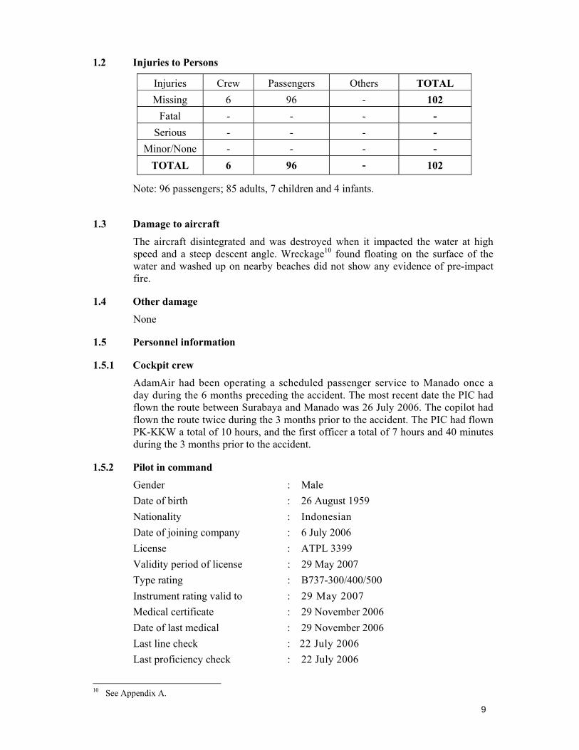
1.2 Injuries to Persons
Injuries Crew Passengers Others TOTAL Missing 6 96 - 102
Fatal - - - - Serious - - - -
Minor/None - - - - TOTAL 6 96 - 102
Note: 96 passengers; 85 adults, 7 children and 4 infants.
1.3 Damage to aircraft
The aircraft disintegrated and was destroyed when it impacted the water at high speed and a steep descent angle. Wreckage10 found floating on the surface of the water and washed up on nearby beaches did not show any evidence of pre-impact fire.
1.4 Other damage
None
1.5 Personnel information
1.5.1 Cockpit crew
AdamAir had been operating a scheduled passenger service to Manado once a day during the 6 months preceding the accident. The most recent date the PIC had flown the route between Surabaya and Manado was 26 July 2006. The copilot had flown the route twice during the 3 months prior to the accident. The PIC had flown PK-KKW a total of 10 hours, and the first officer a total of 7 hours and 40 minutes during the 3 months prior to the accident.
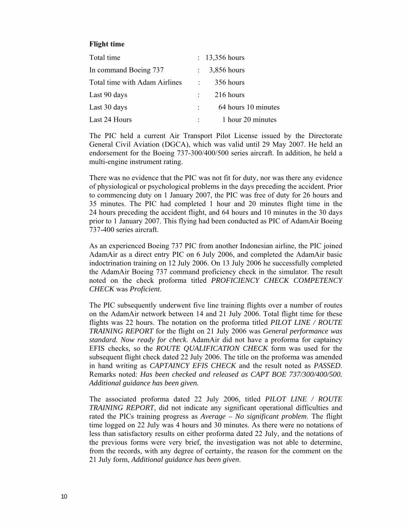
1.5.2 Pilot in command
Gender : Male Date of birth : 26 August 1959 Nationality : Indonesian Date of joining company : 6 July 2006 License : ATPL 3399 Validity period of license : 29 May 2007 Type rating : B737-300/400/500 Instrument rating valid to : 29 May 2007 Medical certificate : 29 November 2006 Date of last medical : 29 November 2006 Last line check : 22 July 2006 Last proficiency check : 22 July 2006
10 See Appendix A.
10
Flight time
Total time : 13,356 hours
In command Boeing 737 : 3,856 hours
Total time with Adam Airlines : 356 hours
Last 90 days : 216 hours
Last 30 days : 64 hours 10 minutes
Last 24 Hours : 1 hour 20 minutes
The PIC held a current Air Transport Pilot License issued by the Directorate General Civil Aviation (DGCA), which was valid until 29 May 2007. He held an endorsement for the Boeing 737-300/400/500 series aircraft. In addition, he held a multi-engine instrument rating.
There was no evidence that the PIC was not fit for duty, nor was there any evidence of physiological or psychological problems in the days preceding the accident. Prior to commencing duty on 1 January 2007, the PIC was free of duty for 26 hours and 35 minutes. The PIC had completed 1 hour and 20 minutes flight time in the 24 hours preceding the accident flight, and 64 hours and 10 minutes in the 30 days prior to 1 January 2007. This flying had been conducted as PIC of AdamAir Boeing 737-400 series aircraft.
As an experienced Boeing 737 PIC from another Indonesian airline, the PIC joined AdamAir as a direct entry PIC on 6 July 2006, and completed the AdamAir basic indoctrination training on 12 July 2006. On 13 July 2006 he successfully completed the AdamAir Boeing 737 command proficiency check in the simulator. The result noted on the check proforma titled PROFICIENCY CHECK COMPETENCY CHECK was Proficient.
The PIC subsequently underwent five line training flights over a number of routes on the AdamAir network between 14 and 21 July 2006. Total flight time for these flights was 22 hours. The notation on the proforma titled PILOT LINE / ROUTE TRAINING REPORT for the flight on 21 July 2006 was General performance was standard. Now ready for check. AdamAir did not have a proforma for captaincy EFIS checks, so the ROUTE QUALIFICATION CHECK form was used for the subsequent flight check dated 22 July 2006. The title on the proforma was amended in hand writing as CAPTAINCY EFIS CHECK and the result noted as PASSED. Remarks noted: Has been checked and released as CAPT BOE 737/300/400/500. Additional guidance has been given.
The associated proforma dated 22 July 2006, titled PILOT LINE / ROUTE TRAINING REPORT, did not indicate any significant operational difficulties and rated the PICs training progress as Average – No significant problem. The flight time logged on 22 July was 4 hours and 30 minutes. As there were no notations of less than satisfactory results on either proforma dated 22 July, and the notations of the previous forms were very brief, the investigation was not able to determine, from the records, with any degree of certainty, the reason for the comment on the 21 July form, Additional guidance has been given.
11
The check pilot subsequently informed the NTSC that the additional guidance he provided the PIC was to ensure that he understood the deficiencies noted during the check flight so they would not be repeated.
The PIC had completed a course covering the Boeing 737-400 IRS as part of the Boeing 737-400 systems type rating course. The navigation section of the aircraft systems syllabus covered IRS. However, the PIC had not received IRS training covering partial or complete IRS system failures.
At the time of the accident, AdamAir did not provide their pilots with aircraft upset recovery training, nor was this required by regulation. There was no evidence that the PIC had completed a course of training, or been checked in a simulator, for proficiency in aircraft upset recovery, including spatial disorientation and situational awareness.
The PIC completed Boeing 737-400 aircraft systems recurrency training on 8 February 2006 and he completed Crew Resource Management (CRM) recurrency training on 23 February 2006, while employed by his previous airline. However, he had not completed a CRM course since joining AdamAir in July 2006.
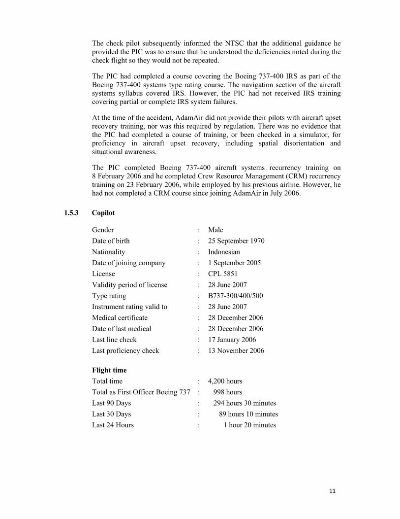
1.5.3 Copilot
Gender : Male Date of birth : 25 September 1970 Nationality : Indonesian Date of joining company : 1 September 2005 License : CPL 5851 Validity period of license : 28 June 2007 Type rating : B737-300/400/500 Instrument rating valid to : 28 June 2007 Medical certificate : 28 December 2006 Date of last medical : 28 December 2006 Last line check : 17 January 2006 Last proficiency check : 13 November 2006 Flight time Total time : 4,200 hours Total as First Officer Boeing 737 : 998 hours Last 90 Days : 294 hours 30 minutes Last 30 Days : 89 hours 10 minutes Last 24 Hours : 1 hour 20 minutes
12
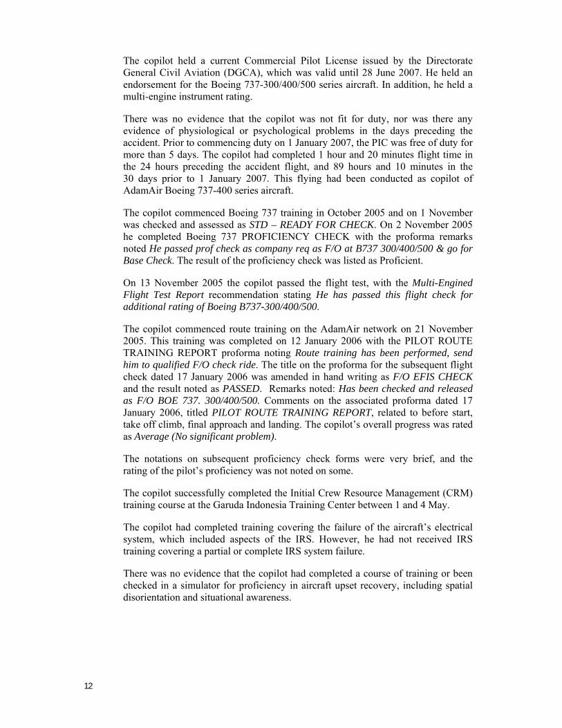
The copilot held a current Commercial Pilot License issued by the Directorate General Civil Aviation (DGCA), which was valid until 28 June 2007. He held an endorsement for the Boeing 737-300/400/500 series aircraft. In addition, he held a multi-engine instrument rating.
There was no evidence that the copilot was not fit for duty, nor was there any evidence of physiological or psychological problems in the days preceding the accident. Prior to commencing duty on 1 January 2007, the PIC was free of duty for more than 5 days. The copilot had completed 1 hour and 20 minutes flight time in the 24 hours preceding the accident flight, and 89 hours and 10 minutes in the 30 days prior to 1 January 2007. This flying had been conducted as copilot of AdamAir Boeing 737-400 series aircraft.
The copilot commenced Boeing 737 training in October 2005 and on 1 November was checked and assessed as STD – READY FOR CHECK. On 2 November 2005 he completed Boeing 737 PROFICIENCY CHECK with the proforma remarks noted He passed prof check as company req as F/O at B737 300/400/500 & go for Base Check. The result of the proficiency check was listed as Proficient.
On 13 November 2005 the copilot passed the flight test, with the Multi-Engined Flight Test Report recommendation stating He has passed this flight check for additional rating of Boeing B737-300/400/500.
The copilot commenced route training on the AdamAir network on 21 November 2005. This training was completed on 12 January 2006 with the PILOT ROUTE TRAINING REPORT proforma noting Route training has been performed, send him to qualified F/O check ride. The title on the proforma for the subsequent flight check dated 17 January 2006 was amended in hand writing as F/O EFIS CHECK and the result noted as PASSED. Remarks noted: Has been checked and released as F/O BOE 737. 300/400/500. Comments on the associated proforma dated 17 January 2006, titled PILOT ROUTE TRAINING REPORT, related to before start, take off climb, final approach and landing. The copilot’s overall progress was rated as Average (No significant problem).
The notations on subsequent proficiency check forms were very brief, and the rating of the pilot’s proficiency was not noted on some.
The copilot successfully completed the Initial Crew Resource Management (CRM) training course at the Garuda Indonesia Training Center between 1 and 4 May.
The copilot had completed training covering the failure of the aircraft’s electrical system, which included aspects of the IRS. However, he had not received IRS training covering a partial or complete IRS system failure.
There was no evidence that the copilot had completed a course of training or been checked in a simulator for proficiency in aircraft upset recovery, including spatial disorientation and situational awareness.
13
1.6 Aircraft Information
1.6.1 Aircraft Data
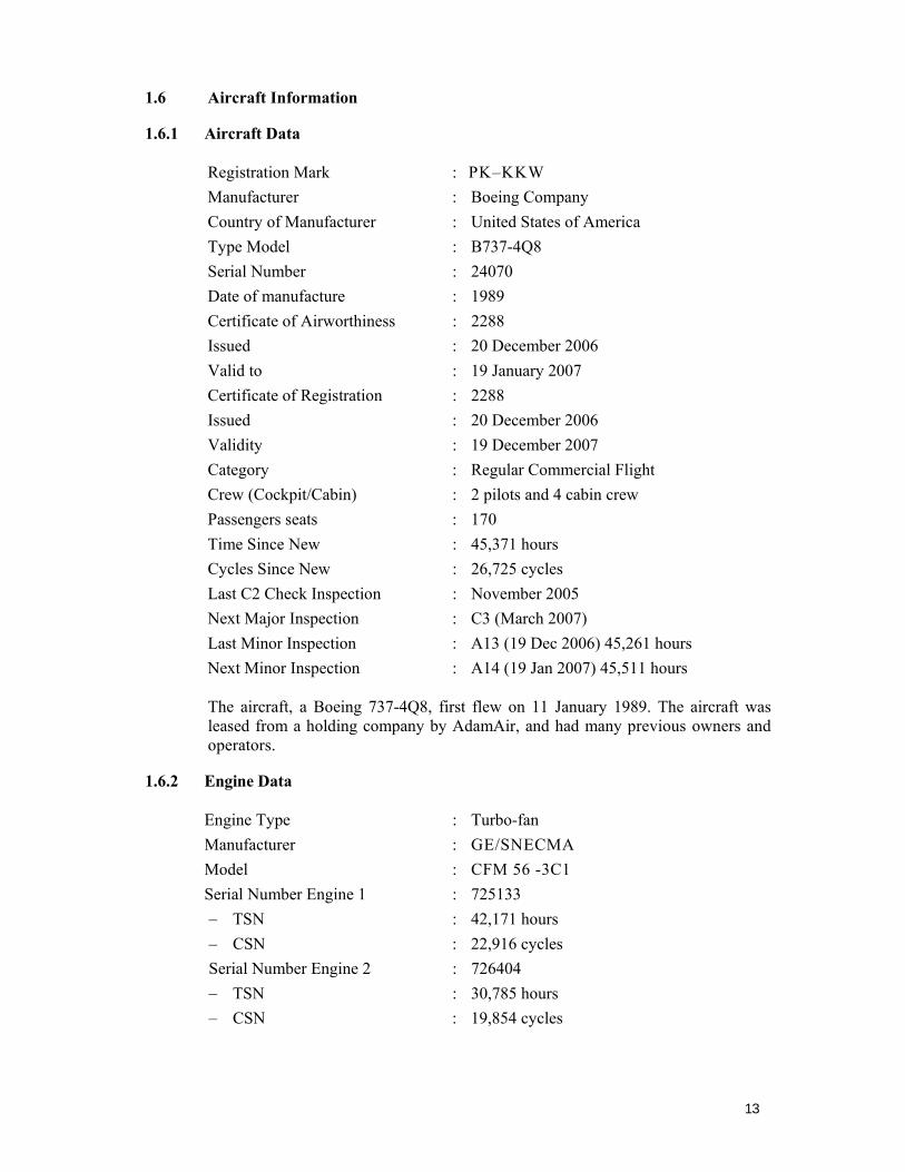
Registration Mark : PK–KKW Manufacturer : Boeing Company Country of Manufacturer : United States of America Type Model : B737-4Q8 Serial Number : 24070 Date of manufacture : 1989 Certificate of Airworthiness : 2288 Issued : 20 December 2006 Valid to : 19 January 2007 Certificate of Registration : 2288 Issued : 20 December 2006 Validity : 19 December 2007 Category : Regular Commercial Flight Crew (Cockpit/Cabin) : 2 pilots and 4 cabin crew Passengers seats : 170 Time Since New : 45,371 hours Cycles Since New : 26,725 cycles Last C2 Check Inspection : November 2005 Next Major Inspection : C3 (March 2007) Last Minor Inspection : A13 (19 Dec 2006) 45,261 hours Next Minor Inspection : A14 (19 Jan 2007) 45,511 hours
The aircraft, a Boeing 737-4Q8, first flew on 11 January 1989. The aircraft was leased from a holding company by AdamAir, and had many previous owners and operators.
1.6.2 Engine Data
Engine Type : Turbo-fan Manufacturer : GE/SNECMA Model : CFM 56 -3C1 Serial Number Engine 1 : 725133 – TSN : 42,171 hours – CSN : 22,916 cycles Serial Number Engine 2 : 726404 – TSN : 30,785 hours – CSN : 19,854 cycles
14
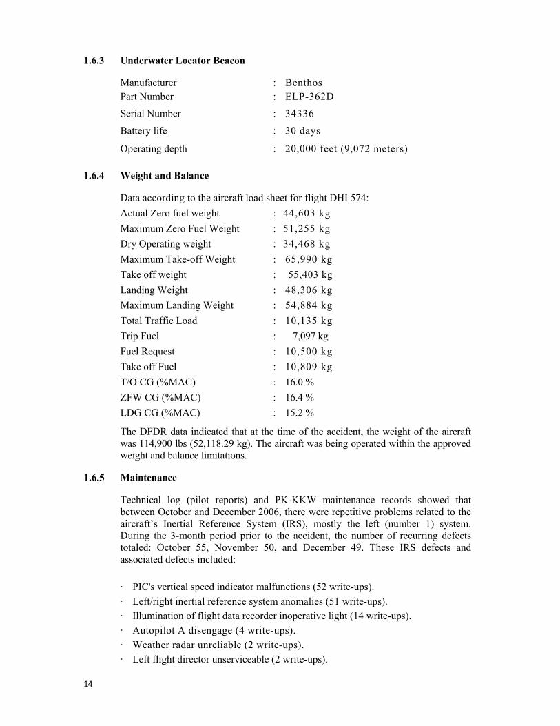
1.6.3 Underwater Locator Beacon
Manufacturer : Benthos Part Number : ELP-362D
Serial Number : 34336
Battery life : 30 days
Operating depth : 20,000 feet (9,072 meters)
1.6.4 Weight and Balance
Data according to the aircraft load sheet for flight DHI 574: Actual Zero fuel weight : 44,603 kg Maximum Zero Fuel Weight : 51,255 kg Dry Operating weight : 34,468 kg Maximum Take-off Weight : 65,990 kg Take off weight : 55,403 kg Landing Weight : 48,306 kg Maximum Landing Weight : 54,884 kg Total Traffic Load : 10,135 kg Trip Fuel : 7,097 kg Fuel Request : 10,500 kg Take off Fuel : 10,809 kg T/O CG (%MAC) : 16.0 % ZFW CG (%MAC) : 16.4 % LDG CG (%MAC) : 15.2 %
The DFDR data indicated that at the time of the accident, the weight of the aircraft was 114,900 lbs (52,118.29 kg). The aircraft was being operated within the approved weight and balance limitations.
1.6.5 Maintenance
Technical log (pilot reports) and PK-KKW maintenance records showed that between October and December 2006, there were repetitive problems related to the aircraft’s Inertial Reference System (IRS), mostly the left (number 1) system. During the 3-month period prior to the accident, the number of recurring defects totaled: October 55, November 50, and December 49. These IRS defects and associated defects included:
· PIC's vertical speed indicator malfunctions (52 write-ups). · Left/right inertial reference system anomalies (51 write-ups). · Illumination of flight data recorder inoperative light (14 write-ups). · Autopilot A disengage (4 write-ups). · Weather radar unreliable (2 write-ups). · Left flight director unserviceable (2 write-ups).
15
The actions to rectify the defects were mainly re-racking, contact cleaning, and relay replacement. See section 1.18.10 for further information.
The operator informed the investigation that for their B737 fleet, there were 5 (five) spare IRUs. Two had an interchangeable part number for PK-KKW. A replacement unit for PK-KKW had a delivery lead time of approximately 6 months.
Line maintenance rectification action was limited to re-racking and swapping IRU positions and associated components, resetting circuit breakers and cleaning connections when the faults became repetitive
The AdamAir Continuous Airworthiness Maintenance Program approved by DGCA was supported by a Reliability Control Program (RCP). However, the RCP did not cover component reliability. There was no evidence that AdamAir included component reliability in their RCP, to ensure the effectiveness of the airworthiness of the aircraft components for the AdamAir fleet, at the time of the accident. There was also no evidence of AdamAir’s maintenance management controlling the repetitive defects on their fleet prior to the accident.
Following the accident, AdamAir assigned a Trouble Shooting Team led by a supervisor, to support the line maintenance engineers to solve the repetitive IRS and other recurring airworthiness maintenance problems.
However, the IRS problems had not been resolved in the AdamAir fleet by the end of November 2007. Maintenance records showed that other aircraft in the fleet: PK-KKC, KMD, KME, KKG, KKI, KKM, KKR, KKT, and KKU continued to have IRS/IRU problems. For example, KKC recorded 8 IRS/IRU defects in October and 19 in November 2007. KKE recorded 6 IRS/IRU defects in October and KMD 8 and KKI 5 in November 2007. There were 82 IRS/IRU problems logged during the September, October, November 2007 period.
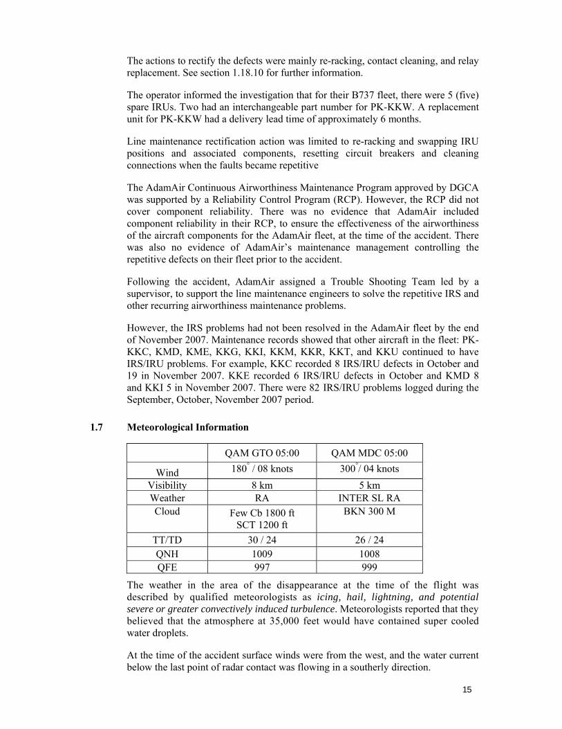
1.7 Meteorological Information
QAM GTO 05:00 QAM MDC 05:00
Wind 180° / 08 knots 300°/ 04 knots Visibility 8 km 5 kmWeather RA INTER SL RA Cloud Few Cb 1800 ft
SCT 1200 ft BKN 300 M
TT/TD 30 / 24 26 / 24 QNH 1009 1008 QFE 997 999
The weather in the area of the disappearance at the time of the flight was described by qualified meteorologists as icing, hail, lightning, and potential severe or greater convectively induced turbulence. Meteorologists reported that they believed that the atmosphere at 35,000 feet would have contained super cooled water droplets.
At the time of the accident surface winds were from the west, and the water current below the last point of radar contact was flowing in a southerly direction.
16
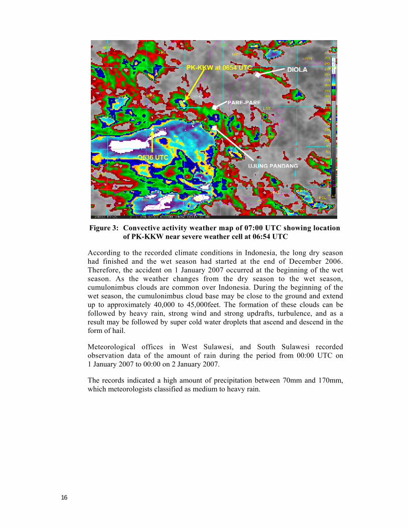
Figure 3: Convective activity weather map of 07:00 UTC showing location
of PK-KKW near severe weather cell at 06:54 UTC
According to the recorded climate conditions in Indonesia, the long dry season had finished and the wet season had started at the end of December 2006. Therefore, the accident on 1 January 2007 occurred at the beginning of the wet season. As the weather changes from the dry season to the wet season, cumulonimbus clouds are common over Indonesia. During the beginning of the wet season, the cumulonimbus cloud base may be close to the ground and extend up to approximately 40,000 to 45,000feet. The formation of these clouds can be followed by heavy rain, strong wind and strong updrafts, turbulence, and as a result may be followed by super cold water droplets that ascend and descend in the form of hail.
Meteorological offices in West Sulawesi, and South Sulawesi recorded observation data of the amount of rain during the period from 00:00 UTC on 1 January 2007 to 00:00 on 2 January 2007.
The records indicated a high amount of precipitation between 70mm and 170mm, which meteorologists classified as medium to heavy rain.

17
Figure 4: Satellite image of clouds over Indonesia 1 January 2007 at 06:00
UTC
The cloud formation is shown in the satellite image as a thick white image and includes the cumulonimbus clouds that produce strong wind, turbulence, heavy rain and super cooled water droplets in the form of hail.
The image shows the cloud formation on the route between Surabaya and Manado (Adam 574 track). According to the Meteorological Office in Makassar, at 00:00 UTC on 1 January 2007 the temperature layer was unstable and the wind shear (vertical differences) was between 30,000 feet and 50,000 feet. In the cumulonimbus cloud there was a movement of the super cold water droplets that was calculated up to 33,000 feet, but may have reached 40,000 feet.
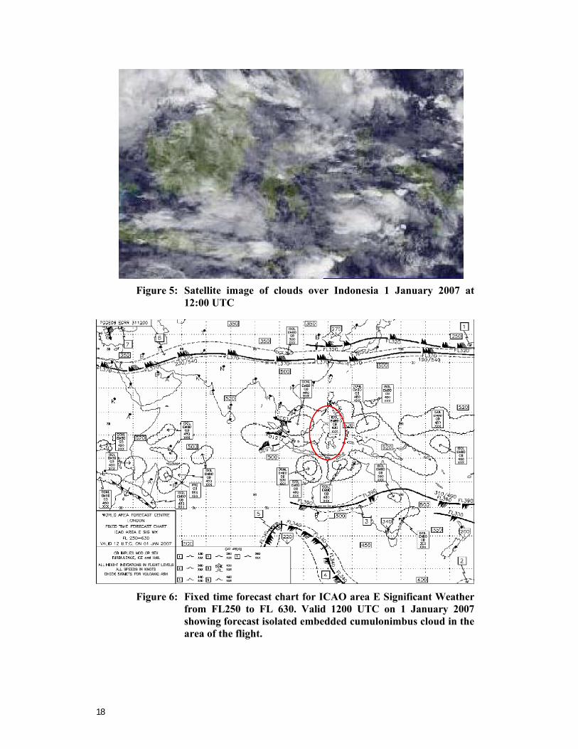
From the data recorded at 12:00 UTC, the stable lapse rate showed that the weather during the night would have improved, however super cold water was still possible.
However, the exact weather in the accident area at the time of the accident could not be determined. It was considered on the available data that the visibility at the time of the loss of control was likely to have been marginal visual meteorological conditions.
18
Figure 5: Satellite image of clouds over Indonesia 1 January 2007 at
12:00 UTC
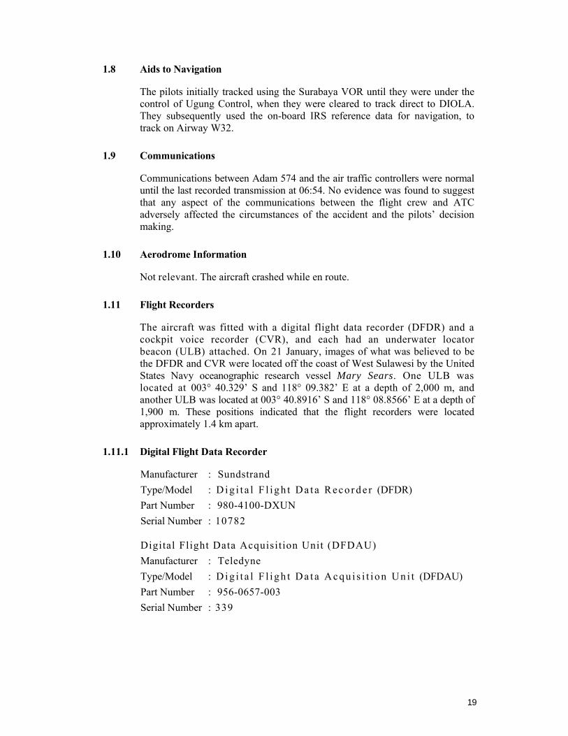
Figure 6: Fixed time forecast chart for ICAO area E Significant Weather
from FL250 to FL 630. Valid 1200 UTC on 1 January 2007 showing forecast isolated embedded cumulonimbus cloud in the area of the flight.
19
1.8 Aids to Navigation
The pilots initially tracked using the Surabaya VOR until they were under the control of Ugung Control, when they were cleared to track direct to DIOLA. They subsequently used the on-board IRS reference data for navigation, to track on Airway W32.
1.9 Communications
Communications between Adam 574 and the air traffic controllers were normal until the last recorded transmission at 06:54. No evidence was found to suggest that any aspect of the communications between the flight crew and ATC adversely affected the circumstances of the accident and the pilots’ decision making.
1.10 Aerodrome Information
Not relevant. The aircraft crashed while en route.
1.11 Flight Recorders
The aircraft was fitted with a digital flight data recorder (DFDR) and a cockpit voice recorder (CVR), and each had an underwater locator beacon (ULB) attached. On 21 January, images of what was believed to be the DFDR and CVR were located off the coast of West Sulawesi by the United States Navy oceanographic research vessel Mary Sears. One ULB was located at 003° 40.329’ S and 118° 09.382’ E at a depth of 2,000 m, and another ULB was located at 003° 40.8916’ S and 118° 08.8566’ E at a depth of 1,900 m. These positions indicated that the flight recorders were located approximately 1.4 km apart.
1.11.1 Digital Flight Data Recorder
Manufacturer : Sundstrand Type/Model : D i g i t a l F l i g h t D a t a Reco r d e r (DFDR) Part Number : 980-4100-DXUN Serial Number : 10782
Digital Flight Data Acquisition Unit (DFDAU) Manufacturer : Teledyne Type/Model : D i g i t a l F l ig h t D a t a A cqu i s i t i on Un i t (DFDAU) Part Number : 956-0657-003 Serial Number : 339
20
The DFDR was recovered from the seabed on 27 August 2007. The Remote Operated Vehicle (ROV) holding the DFDR was brought to the surface at 06:00 and the DFDR was fully immersed in water and secured in a watertight container in accordance with best practice. See more detail in Section 1.12 Wreckage and impact information.
The DFDR showed that the aircraft was in cruise at Flight Level (FL) 350 (35,000 ft), at a speed of Mach 0.75, with autopilot ‘A’ engaged. Autopilot modes selected by the crew were Heading SEL and VNAV. At 06:56:35, autopilot A was changed from VNAV mode to Altitude Hold mode.
The number-1 (left) IRS, number-1 (left) Electronic Attitude Display indicator (EADI), and the Standby Attitude Direction Indicator (ADI) were available.
The following is from the CVR transcript:
06:56:55.2 PIC put the IRS in attitude [mode on the IRS Mode Selector Unit].
06:56:57.9 Copilot will do sir
06:57:14.0 PIC enter into
06:57:15.9 PIC still fail
06:57:17.6 Copilot fail
06:57:18.2 PIC yes there’s a fault. Select Attitude
06:57:26.1 Copilot IRS mode selector
06:57:28.3 PIC attitude left
06:57:29.3 Copilot left one 06:57:34.0 PIC after this, heading set, enter ya
(setelah ini heading set ya, masukin ya).
06:57:36.0 Sound of autopilot disengage lasting approximately 4 seconds.
When ATT (Attitude) was selected in the IRS Mode Selector Unit, it resulted in the autopilot disengaging. The effect on the copilot’s EADI of switching from NAV to ATT was that the following displays were lost:
· Roll indication · Horizon scale · Pitch scale · Sky/ground shading.
Flight path angle, Acceleration, Pitch Limit display and Traffic Alert and Collision Avoidance System (TCAS), Resolution Advisory (RA) commands are also removed when ATT is selected.
Based on information from the DFDR, attitude data from at least one IRU was valid and contained expected pitch and roll data throughout the incident flight.
The continuity of the recorded parameters also indicates that the IRU source of this data was not switched during the flight.
21
The Ground Proximity Warning System (GPWS) provides bank angle alert11. The GPWS receives IRU attitude data from only the Left IRU. During the flight, the Cockpit Voice Recorder (CVR) recorded bank angle alerts when the aircraft attitude was about 35 degrees right wing down. This is an indication that left IRU was operational and providing attitude data to the GPWS at this time.
Throughout most of the flight, the autopilot had been holding some left wheel (aileron) to hold wings level. Just prior to the autopilot disengaging, the autopilot was holding approximately 5 degrees of left wheel. At 06:57:36, the autopilot disengaged, and the wheel returned to center. This resulted in a slow right roll of approximately 1 degree per second. The roll rate was arrested with the wheel (aileron) at 06:57:45, and again at 06:58:00, but the wheel inputs were momentary, and the aircraft continued to roll to the right.
The aural alert BANK ANGLE, BANK ANGLE, BANK ANGLE, BANK ANGLE occurred at 06:58:10.6 when the aircraft reached 35 degrees of bank angle. Again the bank angle was briefly arrested, but was followed momentarily by a right wing down wheel input.
At 06:58:23, sufficient wheel (approx 15 deg) was used to reverse the roll rate, but again was followed by right wheel input, continuing the right wing down roll rate.
Subsequently the pilot began to pull on the control column (elevator), modestly at first, commanding approximately 1.1g12. As the aircraft rolled right through 60 degrees of bank angle, the pilot began to steadily increase control column pull (elevator), while continuing to roll right. The pitch attitude at 06:58:23 was approximately 5 degrees aircraft nose down. Shortly after, the aircraft’s pitch rate increased to 2.3 deg/sec aircraft nose down. The pitch attitude reached negative 60 degrees (nose down) at 06:58:50. The pitch rate subsequently became positive, reducing the nose-down attitude.
The CVR revealed that both pilots became engrossed with trouble shooting Inertial Reference System (IRS) anomalies for at least the last 13 minutes of the flight, with minimal regard to other flight requirements. For about 46 seconds after the autopilot disengaged, the pilots were completely occupied with trouble shooting. This included attempts to identify the IRS problems, and some attempts at corrective actions of the IRS and the navigation instruments. Even after the first BANK ANGLE, BANK ANGLE, BANK ANGLE, BANK ANGLE alert sounded at 06:58:10.6, the crew did not make timely and appropriate flight control inputs to recover control of the aircraft.
There was no evidence that either of the pilots appropriately referenced the flight instruments.
11 The Boeing Company Flight Crew Operations Manual page 15.20.10 states:
Bank Angle Alert On airplanes with bank angle alert, the aural alert “BANK ANGLE, BANK ANGLE” sounds when roll angle exceeds 35 degrees, 40 degrees, and 45 degrees. Once sounded the alert is silent if bank angle is decreased to 30 degrees.
12 Acceleration - gravitational/g-force (9.80665 m/s²).
22
The aircraft reached a maximum right bank angle of 100 degrees at 06:58:38. At that time, approximately 2g was being commanded by crew action, while the roll rate was being reversed, using an oscillatory wheel input of between 10-20 degrees. Subsequent action was taken to roll the aircraft towards wings level using a bank angle of less than 20 degrees (aileron), with the aircraft rolling left at a rate of approximately 4 degrees per second, towards wings level. During this roll, nose-up elevator in excess of 2gs of force was commanded. Nose-up elevator input continued, resulting in 3g force at 06:58:58 with 42 degrees of bank, then 3.5g by 06:59:04 with 32 degrees of bank. During that time period, airspeed had accelerated past Mmo (0.82) and was approaching Mdive (0.89).
The Boeing Quick Reference Handbook, Maneuvers, Non-Normal Maneuvers, page MAN.1.7, Nose Low Recovery, requires the pilot flying to:
*Roll in the shortest direction to wings level (unload and roll if bank angle is more than 90 degrees). The instruction has a warning note:
Warning: *Excessive use of pitch trim or rudder may aggravate an upset situation or may result in loss of control and/or high structural loads.
The Boeing upset recovery procedure requires roll to wings level before applying nose-up elevator. The DFDR showed that this procedure was not followed by the crew.
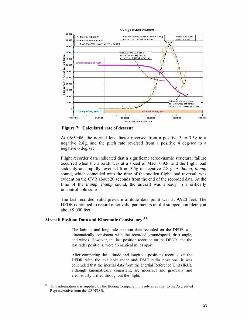
The maximum recorded Mach number reached was 0.926, at 06:58:51. Airspeed exceeded Vdive (400 kcas), and reached a maximum of approximately 490 kcas just prior to the end of recorded data. The descent between recorded data altitudes of 35,008 feet and 9,920 feet took 75 seconds, giving an average vertical speed (rate of sink) of 20,070 feet per minute. The maximum recorded rate of descent was 53,760 feet per minute at 06:58:48. Between 06:58:42 and 06:58:57, the average rate of descent was 46,88 feet per minute, and between 06:59:01 and 06:59:12 was 24,576 feet per minute. (See Figure 7.)
The g forces eventually reached about 3.5gs as the Mach number reached a maximum of 0.926. The 3.5 g force and Mach 0.926 airspeed are beyond the designed limitations of the aircraft. Federal Aviation Regulation (FAR) 25.333 covers maneuver envelopes for structure design. FAR 25.333 shows the v-vs-n maneuvering envelope. At dive speeds, structures are required to maintain integrity 0-2.5g's.
23
Figure 7: Calculated rate of descent
At 06:59:06, the normal load factor reversed from a positive 3 to 3.5g to a negative 2.8g, and the pitch rate reversed from a positive 4 deg/sec to a negative 6 deg/sec.
Flight recorder data indicated that a significant aerodynamic structural failure occurred when the aircraft was at a speed of Mach 0.926 and the flight load suddenly and rapidly reversed from 3.5g to negative 2.8 g. A thump, thump sound, which coincided with the time of the sudden flight load reversal, was evident on the CVR about 20 seconds from the end of the recorded data. At the time of the thump, thump sound, the aircraft was already in a critically uncontrollable state.
The last recorded valid pressure altitude data point was at 9,920 feet. The DFDR continued to record other valid parameters until it stopped completely at about 9,000 feet.
Aircraft Position Data and Kinematic Consistency:13
The latitude and longitude position data recorded on the DFDR was kinematically consistent with the recorded groundspeed, drift angle, and winds. However, the last position recorded on the DFDR, and the last radar positions, were 56 nautical miles apart.
After comparing the latitude and longitude positions recorded on the DFDR with the available radar and DME radio positions, it was concluded that the inertial data from the Inertial Reference Unit (IRU), although kinematically consistent, are incorrect and gradually and erroneously drifted throughout the flight.
13 This information was supplied by the Boeing Company in its role as adviser to the Accredited
Representative from the US NTSB.
24
The parameters determined to be in error are position latitude, position longitude, groundspeed, drift angle, horizontal wind speed, and wind direction.
The accelerometers recorded on the DFDR come from an independent source in the wheel well of the aircraft, and are not from the IRU. The Euler angles (i.e. pitch, roll, and heading) recorded on the DFDR come from laser gyros in the IRU and are considered to be valid.
The position data of the radar and DME radio position ended at the approximate location where the DFDR and CVR were recovered. This confirms that these data position the airplane accurately along its flight path. Therefore, to create a set of data that are both kinematically consistent and having accurate flight path information, the latitude and longitude recorded on the DFDR were corrected to match the radar and radio position data. Seven points were chosen to correct the latitude and longitude position data. These points were chosen to minimize the difference between the radar/radio data, and the corrected latitude and longitude. This method retained the fidelity of the aircraft position data as recorded on the DFDR (higher sample rate), while placing the aircraft accurately along its flight path.
With the corrected latitude and longitude position data, accurate ground speed and ground track were created. These data, along with the recorded airspeed, alpha vane14, and side acceleration were used to calculate the winds during the accident portion of the flight. The vertical winds were small and/or constant, so were disregarded. The result is a kinematically consistent set of data that match the radar and DME radio position data. The resulting wind direction and magnitude agree with the weather soundings conducted at Ujung Pandang Airport (WAAA), Hasanuddin, Indonesia on the day of the accident.
1.11.2 Cockpit Voice Recorder
Manufacturer : Fairchild Type/Model : A100 Part Number : 93A100-80 Serial Number : 59038
The CVR was recovered from the seabed on 28 August 2007. The ROV holding the CVR was brought to the surface at 03:55 and the CVR was fully immersed in water and secured in a watertight container in accordance with best practice. See more detail in Section 1.12 Wreckage and impact information.
The CVR data was aligned with the DFDR data and indicated that the autopilot disengaged, and the autopilot disengage horn sounded at 06:57:36 and lasted approximately 4 seconds before one of the pilots silenced it.
14 Angle of attack meter.
25
At 06:58:10.6, as the aircraft rolled through 35 degrees, the BANK ANGLE, BANK ANGLE, BANK ANGLE, BANK ANGLE, aural alert sounded. At 06:58:15.6 when the aircraft was passing 34,752 feet on descent, the Altitude Deviation alert sounded. At 06:58:35.6, the overspeed warning sounded as the aircraft’s Mach number exceeded Mmo (Mach 0.82). Mach 0.926 was reached at 06:58:51.
Sounds of increasing air noise could be heard on the CVR recording 19 seconds after the overspeed warning. That was followed by a thump, thump sound at 06:59:05. The thump, thump sound occurred shortly after the normal load factor reversed from between 3 and 3.5g to negative 2.8g. CVR recorded data ended about 20 seconds later at 06:59:24.7 as the aircraft descended from 9,920 feet.
1.11.3 Notable facts from the CVR
The recorded CVR data commenced at 06:28:30.
– At 06:29:44 the PIC said the IRS then 5 seconds later commented twenty eight is the difference. This indicated that the PIC had started to recognize a navigation problem between the two IRS; specifically, a significant difference in distance.
– Twenty-nine minutes before the divergence from controlled flight, the passengers were advised that the aircraft was entering bad weather and that they should return to their seats and fasten their seat belts.
– After being cleared to track direct to DIOLA at 06:54:08, and commencing to use the IRS reference data for navigation, the pilots found problems with tracking/IRS readings and subsequently sought their position from MKS.
– During the problems with the navigation instruments (IRS, IRU, FMS, VOR/DME, etc), the pilots believed they were off track and were concerned and confused, but did not raise any concerns with ATC. While they were trouble shooting the problems, they made statements such as: verify position, we can get lost if its like this; we will get lost then; crazy its crazy; this is really bad; the right (unintelligible word) direction; FMS; look at the FMS; the IRS is erroneous; but the fault must be illuminated captain; we can’t just turn off one of the IRS; it doesn’t seem we have it; there isn’t anything; that’s bad; now the left one is good, the right one is different, you are kidding; whoa something is disengaged; this is messed up; yes this is already messed up; its starting to fly like a bamboo ship; we are wrong; do you see its messed up; the EFIS and FMS are messed up; the FMS is confusing himself that’s crazy; put the IRS in attitude; fail; fail; yes there’s a fault.

26
The crew exchanged the following comments between 06:47:10 and 06:50:21, while attempting to identify the apparent IRS malfunction.
· 06:47:10 PIC Have a look at the QRH If the IRS number two is switched off, see what happens.
· 06:47:25 Copilot IRS.
· 06:47:46 PIC Navigation; FMS, look at the FMS.
· 06:48:00 Copilot IRS fault.
· 06:48:02 PIC Eleven four15; it is not fault.
· 06:48:11 Copilot Its not fault.
· 06:48:17 PIC The IRS is erroneous.
· 06:48:20 Copilot But the fault must be illuminated Capt.
· 06:48:23 PIC It is, its not fault.
· 06:48:29 Copilot Yes, on the ground in flight.
· 06:48:32 Copilot This one on the ground.
· 06:48:38 Copilot IRS fault eleven four.
· 06:48:46 PIC Its not fault.
· 06:48:48 Copilot No no no.
· 06:48:50 The word flight was recorded, but the investigation was unable to determine which pilot made the comment.
· 06:49:01 Copilot But the left one is good.
· 06:49:02 PIC Yes, that is why.
· 06:49:05 PIC Can we just turn one of these IRS off?
· 06:49:05 Copilot It doesn’t seem we have to.
· 06:49:09 PIC There isn’t anything,
· 06:49:36 PIC There isn’t anything.
· 06:50:21 Copilot Radial two nine zero, yup.
The PIC asked the copilot to verify their position with UPG control at the following times:
· 06:43:21.5 · 06.50:35.6 · 06:50:37.2 · 06.55.51.5
15 Eleven four was referring to the QRH Non-Normal Checklist, Flight Management, Navigation Section
title IRS Fault at page11.4. There are two procedures; fault on ground and fault in flight. See Appendix C.
27
After the PIC’s first request, the copilot replied I’ll ask? Following the third and fourth requests the copilot asked UPG Control to verify their position.
– The UPG controller verified their position by giving radial and distance relative to the MKS VOR. However, the crew did not use that information in an attempt to verify the IRS reading.
– At 06:56:55.2 the PIC instructed the copilot to switch the IRS selector to ATT (attitude).
– At 06:57:28.3, after questioning if the PIC meant the left IRS, the copilot made a selection. DFDR data showed that the right IRS was switched to ATT.
– Selecting the IRS to ATT disengaged the autopilot, as designed, and at 06:57:36.0, the autopilot disengage aural warning sounded, lasting approximately 4 seconds. The aircraft was in a straight, wings level flight at 35,000 feet altitude, on a heading of 070 degrees. Following the autopilot disengaging, neither pilot flew the aircraft to maintain wings level flight for 30 seconds as specified in Chapter 11 of the QRH procedures16.
– From 06:58:10.6 the Bank Angle alert sounded four times.
– 06:58:12 PIC Put it back on nav again, put it back on nav again (taro nav lagi taro nav lagi).
– 06:58:14 Copilot Yes.
– 06:58:15 PIC Put on nav again, put on nav again.
– 06:58:16 The Altitude Deviation alert sounded.
– 06:58:19 Copilot Nav
– 06:58:20 PIC Don’t turn it! This is our heading.
– 06:58:58 Copilot Pull up! Pull up! Pull up! Pull up! Pull up! Pull up!
– A thump, thump sound was recorded at 06:59:05
16 See paragraph 1.17.1 and Appendix C.
28
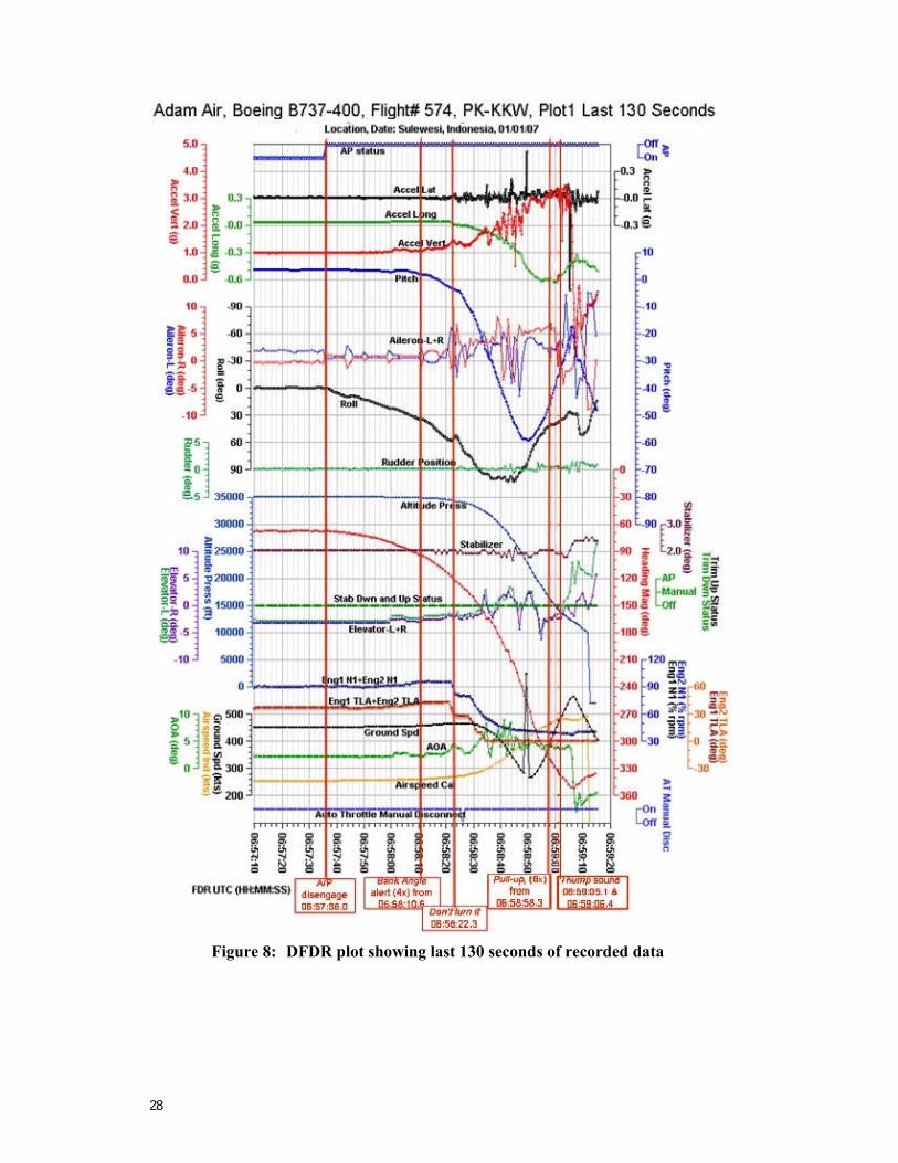
Figure 8: DFDR plot showing last 130 seconds of recorded data
29
1.12 Wreckage and impact information
The highly fragmented aircraft wreckage was on an area of the seabed about 400 meters by 500 meters, between the two ULBs. The information recorded on the DFDR provided confirmation that the aircraft had impacted the water at very high speed and at a steep impact angle.
The wreckage was in a relative small area due to the steep impact angle. The high speed and steep impact angle are considered to have generated a huge pressure wave in the inside of the aircraft fuselage causing the fuselage to explode. This phenomena would have similarly affected other major aircraft structural components. The combination of the pressure wave, and high kinetic energy at impact, caused the aircraft to break up and become fragmented.
Some passengers’ personal effects such as luggage and school bag were observed, but no human remains were found.
1.13 Medical and Pathological Information
No relevant evidence.
1.14 Fire
There was no evidence of fire on the recovered wreckage.
1.15 Search and survival aspects
1.15.1 Search
The Indonesian Navy, Army, Air Force, Police, and Search and Rescue organization, a Singaporean Air Force Fokker 50 aircraft, the USNS Mary Sears, National Transportation Safety Committee of Indonesia, Air Accident Investigation Bureau of Singapore, Singapore Navy Divers, and other resources searched for the wreckage of PK-KKW in the Makassar Strait, in the vicinity of the last radar return. Weather in the area during the search was good. No underwater locator beacon returns were heard. The Mary Sears was required to pass within 500 meters of a beacon before it could detect a return.
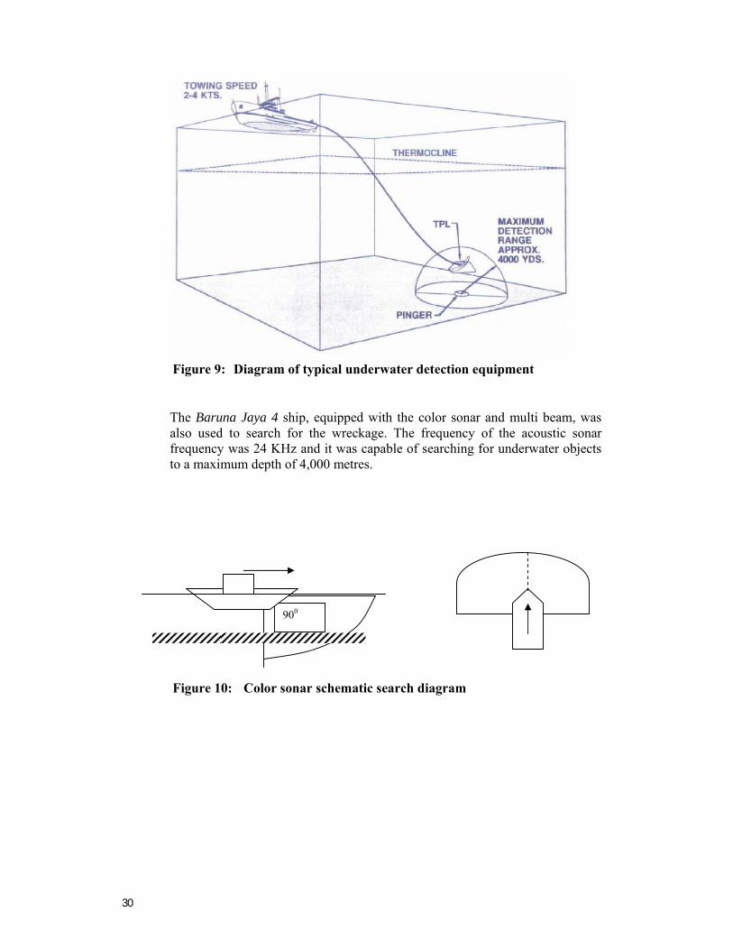
The US Navy Supervisor of Salvage shipped a towed pinger locator (TPL) from Washington, DC, to Makassar. This device is a sonic detector with umbilical cable capable of detecting the underwater locator beacons from the PK-KKW flight data recorder and cockpit voice recorder (if they are still operating), down to a depth of 20,000 feet.
30
Figure 9: Diagram of typical underwater detection equipment
The Baruna Jaya 4 ship, equipped with the color sonar and multi beam, was also used to search for the wreckage. The frequency of the acoustic sonar frequency was 24 KHz and it was capable of searching for underwater objects to a maximum depth of 4,000 metres.
Figure 10: Color sonar schematic search diagram
900
31
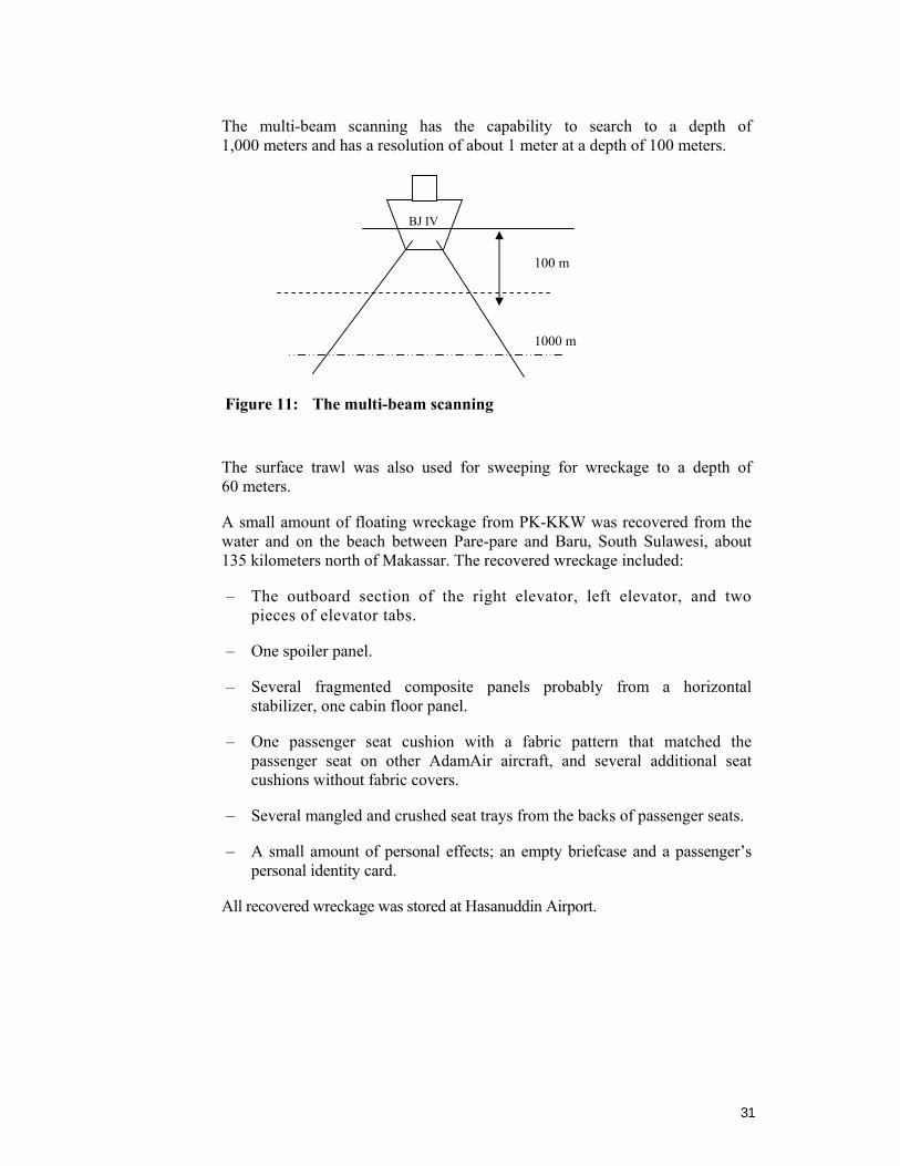
The multi-beam scanning has the capability to search to a depth of 1,000 meters and has a resolution of about 1 meter at a depth of 100 meters.
Figure 11: The multi-beam scanning
The surface trawl was also used for sweeping for wreckage to a depth of 60 meters.
A small amount of floating wreckage from PK-KKW was recovered from the water and on the beach between Pare-pare and Baru, South Sulawesi, about 135 kilometers north of Makassar. The recovered wreckage included:
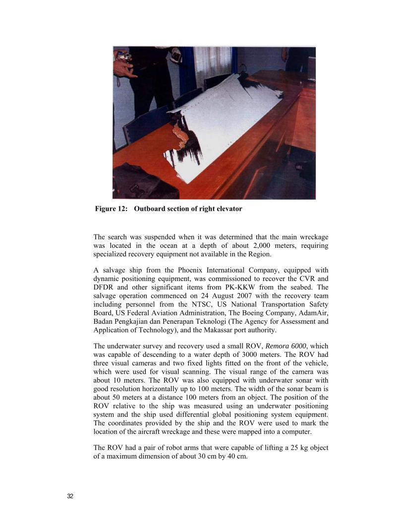
– The outboard section of the right elevator, left elevator, and two pieces of elevator tabs.
– One spoiler panel.
– Several fragmented composite panels probably from a horizontal stabilizer, one cabin floor panel.
– One passenger seat cushion with a fabric pattern that matched the passenger seat on other AdamAir aircraft, and several additional seat cushions without fabric covers.
– Several mangled and crushed seat trays from the backs of passenger seats.
– A small amount of personal effects; an empty briefcase and a passenger’s personal identity card.
All recovered wreckage was stored at Hasanuddin Airport.
BJ IV
1000 m
100 m
32
Figure 12: Outboard section of right elevator
The search was suspended when it was determined that the main wreckage was located in the ocean at a depth of about 2,000 meters, requiring specialized recovery equipment not available in the Region.
A salvage ship from the Phoenix International Company, equipped with dynamic positioning equipment, was commissioned to recover the CVR and DFDR and other significant items from PK-KKW from the seabed. The salvage operation commenced on 24 August 2007 with the recovery team including personnel from the NTSC, US National Transportation Safety Board, US Federal Aviation Administration, The Boeing Company, AdamAir, Badan Pengkajian dan Penerapan Teknologi (The Agency for Assessment and Application of Technology), and the Makassar port authority.
The underwater survey and recovery used a small ROV, Remora 6000, which was capable of descending to a water depth of 3000 meters. The ROV had three visual cameras and two fixed lights fitted on the front of the vehicle, which were used for visual scanning. The visual range of the camera was about 10 meters. The ROV was also equipped with underwater sonar with good resolution horizontally up to 100 meters. The width of the sonar beam is about 50 meters at a distance 100 meters from an object. The position of the ROV relative to the ship was measured using an underwater positioning system and the ship used differential global positioning system equipment. The coordinates provided by the ship and the ROV were used to mark the location of the aircraft wreckage and these were mapped into a computer.
The ROV had a pair of robot arms that were capable of lifting a 25 kg object of a maximum dimension of about 30 cm by 40 cm.
33
Debris position as mentioned by Mary Sears
ULB I ULB II
003° 40.329’ S 118° 09.382’ E 003° 40.8916’ S 118° 08.8566’ E
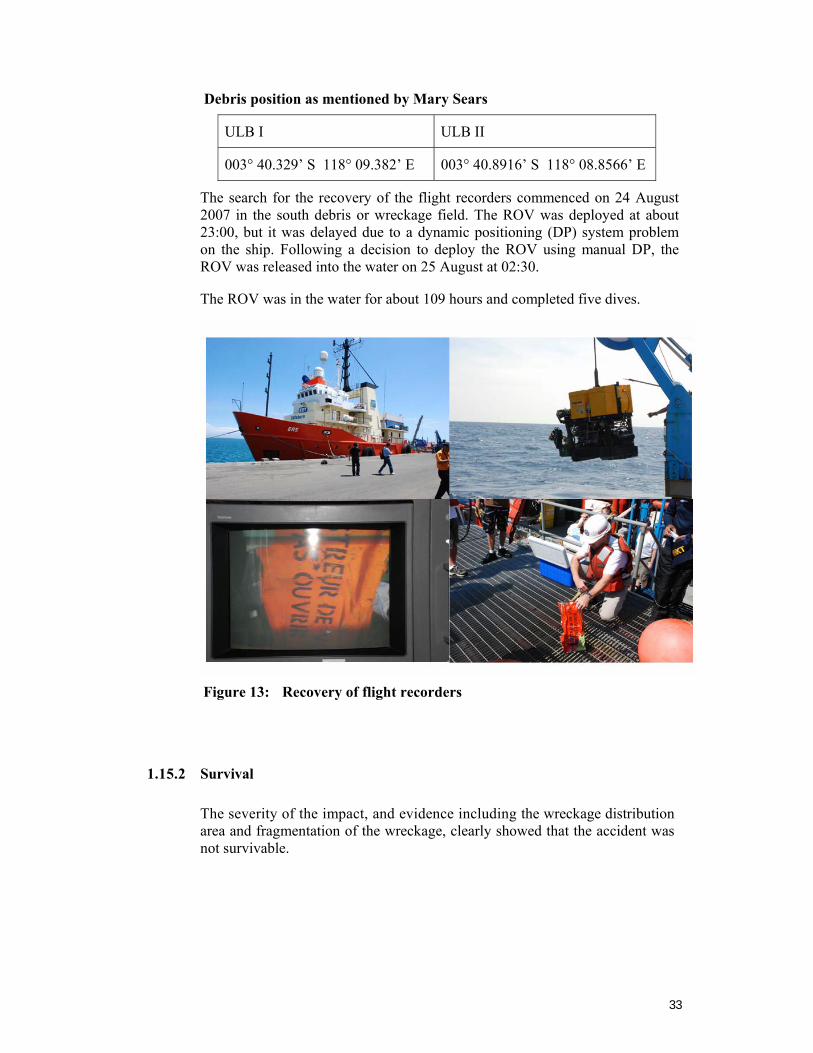
The search for the recovery of the flight recorders commenced on 24 August 2007 in the south debris or wreckage field. The ROV was deployed at about 23:00, but it was delayed due to a dynamic positioning (DP) system problem on the ship. Following a decision to deploy the ROV using manual DP, the ROV was released into the water on 25 August at 02:30.
The ROV was in the water for about 109 hours and completed five dives.
Figure 13: Recovery of flight recorders
1.15.2 Survival
The severity of the impact, and evidence including the wreckage distribution area and fragmentation of the wreckage, clearly showed that the accident was not survivable.
34
1.16 Test and Research
As an adviser to the US Accredited Representative from the US NTSB, The Boeing Company assisted the investigation with a number of aspects relating to the DFDR data and interpretation of the data. They provided the following information with respect to their simulation work.
Equivalent Wheel Position
To facilitate work with the desktop engineering simulator, an equivalent wheel position was derived from the measured left and right aileron position, using the following equation:
Equivalent Wheel = {(left aileron – right aileron) / 2} X (wheel-to-aileron gearing)
Simulation of the Accident
The Boeing 737-400 desktop engineering simulation was used to recreate the accident. The desktop simulation represents the airplane aerodynamics with models that have been updated to match flight test data. The desktop tool offers flexibility in being able to drive with flight data and apply mathematical pilot models. For this analysis, the recorded elevator position and the calculated equivalent wheel position were used as control inputs to the simulation. In addition, mathematical pilot models were used to augment the elevator and wheel inputs to match the DFDR pitch and roll attitude more accurately. Throttle lever inputs were used to match the DFDR engine N1 and flight path. Horizontal wind magnitude and wind direction calculated from the DFDR data and corrected inertial data, were also input into the simulation. No vertical winds were used.
The accident airplane had a small roll asymmetry evident in the recorded left and right aileron positions. This roll asymmetry is equivalent to 0.0005 of aerodynamic rolling moment coefficient. To simulate this asymmetry, an aerodynamic rolling moment coefficient bias of 0.0005 was added to the simulation, and remained in throughout the duration of the match.
A baseline simulation match of the accident was performed between 06:57:00 and 06:57:20. This covers the time during cruise prior to autopilot disengaging to approximately 440 kcas (a speed beyond Vdive). The baseline match shows that the recorded airplane performance and motion is what would be expected for the recorded control inputs.
35
1.17 Organizational and Management Information
1.17.1 Adam SkyConnection Airlines (AdamAir)
Aircraft Owner : Wells Fargo Bank Northwest, National Association
Aircraft Operator : PT. Adam Sky Connection Airlines Trading as : AdamAir Address : Jl. Gedong Panjang No.28
Kelurahan Pekajon Kecamatan Tambora Jakarta Barat
Certificate Number : No.AOC/1 21-036
AdamAir informed the investigation that prior to the accident their management team included a Flight Standard and Support team. The Flight Standard and Support Manager’s duties were contained in a letter of appointment signed by the EVP Operation. The letter of appointment, Number AA/EVPO-SK/No.001/IV/05, dated 17 April 2006, was addressed to a Captain (named in the letter), with the position reference ‘Flight Standard Manager’. The listed duties did not include responsibility for the aircraft operations manuals.
AdamAir advised the investigation that they did not hold a master library copy of the Boeing 737–300/400/500 Flight Crew Operations Manual (FCOM) and the Quick Reference Handbook (QRH) used in PK-KKW. The only copy specifically for PK-KKW was on board the aircraft at the time of the accident. The on-board FCOM and QRH manuals were the copies received from the lessor at the time PK-KKW was delivered to AdamAir on 20 December 2005. The revision number of the FCOM was B15/03Dec04. The revision number of the QRH was NC4/03Dec04. There was no evidence that document revision status for the FCOM and QRH was maintained for PK-KKW between 20 December 2005 and the time of the accident.
AdamAir pilots were issued with a personal reference version of the Boeing 737–300/400/500 Flight Crew Operations Manual (FCOM) and the Quick Reference Handbook (QRH) produced from generic copies downloaded from the web site myboeingfleet.com, for personal use for training reference purposes.17 The myboeingfleet.com web site clearly stated that the web-based manuals were intended for information purposes only and are not intended for operational use, but rather to inform pilots of the latest Boeing procedures and checklists. The caveat on the web site stated options covered in these manuals may not match your particular airplane configuration. Do not use this manual or any of the related materials in any way in the operation, use or maintenance of any aircraft.
17 Appendix B is a copy of the generic version of the QRH 11.5 from myboeingfleet.com web site.
Appendix C is a copy of the generic version of the QRH 11.5 as supplied to AdamAir pilots.
36
The operator’s flying operations management pilots, who were interviewed by the NTSC after the accident, initially were not able to explain the Boeing 737 IRS system, including the IRS abnormal system. This appeared to be indicative of a serious systems knowledge deficiency in the airline, even though the airline had previously experienced an IRS malfunction in a Boeing 737, PK-KKE, which resulted in a serious incident.
However, during a subsequent interview the operations management pilots displayed better knowledge of the Boeing 737 IRS system, including the IRS abnormal system.
AdamAir informed the NTSC that they held regular meetings between the Operation Department and the Maintenance Engineering Department. However, there was no evidence that the airline’s management was aware of the seriousness of the unresolved and recurring defects, despite having experienced such a serious IRS problem previously (PK-KKE).
AdamAir outsourced all major maintenance tasks. The airline only had the capability to perform line maintenance tasks.
The AdamAir syllabus of pilot training did not cover partial IRS failure training. There was no evidence that the pilots received training covering unexpected autopilot disengaging, and the knowledge and skills required for manual handling and using the standby instruments in the event of an IRS failure.
Even after the previous serious incident involving PK-KKE, AdamAir did not include automation failure training, or IRS failure recovery training in their initial or recurrent training syllabus.
At the time of the accident, AdamAir did not provide their pilots with IRS malfunction corrective action training in the simulator, nor did they provide aircraft upset recovery training or proficiency checks, even though the training manuals were available from the Boeing Company.
1.17.2 Directorate General Civil Aviation (DGCA) surveillance of AdamAir flight operations and airworthiness
In accordance CASRs, Indonesian operators are required to provide training in emergency or abnormal situations or procedures. However, at the time of the accident, the Indonesian regulations did not specifically require upset recovery to be included in their flight operations training.
Since 1998, the aviation industry and governments throughout the world have promoted such training as being highly desirable for crews that are operating large turbo-fan, swept-wing aircraft seating more than one hundred passengers. The training material is available from aircraft manufacturers.
The last DGCA airworthiness inspection of AdamAir prior to the accident, was conducted on 1 December 2006 by DGCA Airworthiness Inspectors and involved an inspection of PK-KKW.
37
The inspectors noted 21 deficiencies; two related to IRS:
• Item 11. IRS#1BLANK WHEN DESCENT.
• Item 12. IRS#2 deviates until 16 Nm WHEN CRUISING AND DESCENT.
DGCA wrote to AdamAir on 4 December 2006 drawing their attention to the deficiencies and issued the Certificate of Airworthiness for PK-KKW, subject to rectification of the 21 deficiencies.
While DGCA provided the NTSC with evidence from AdamAir Technical Reports with respect to PK-KKW covering the period January to December 2006, there was no evidence that DGCA or AdamAir had taken appropriate and adequate action prior to 4 December 2006 to rectify the numerous recurring IRS defects. Technical log (pilot reports) and maintenance records showed an extremely high number of repetitive problems related to the Inertial Reference System (IRS), mostly the left (number-1) system on PK-KKW. There was no evidence, that prior to December 2006, DGCA was actively ensuring that AdamAir was rectifying the numerous IRS defects on other aircraft in the AdamAir Boeing 737 fleet.
The AdamAir Continuous Airworthiness Maintenance Program approved by DGCA was supported by a Reliability Control Program (RCP). However, the RCP did not cover component reliability. There was no evidence that DGCA was aware that the AdamAir component reliability RCP did not assure the effectiveness of the airworthiness of the aircraft components for the AdamAir fleet.
1.18 Additional Information
1.18.1 Standby Attitude Indicator – Erection to false vertical
Gyro erection to a false vertical under moderate acceleration (fore-aft and/or turning) is a known limitation associated with traditional vertical gyros and standby attitude indicators (ADIs). Typically, a level in the vertical gyros and in the standby ADIs is used to provide a short term vertical reference to prevent erection to a false vertical under aircraft acceleration. The level senses the gravitational acceleration as well as acceleration due to an aircraft maneuver. If the acceleration exceeds the trip point set on the level, then erection is cut off to prevent erection to a false vertical. However, under moderate acceleration, below the level's trip point, as the acceleration does not trip the erection cut off, the gyro could erect to a false vertical if the condition is continued for a prolonged period. (The level sums the gravitational acceleration and the aircraft maneuver acceleration and the result is the sensed vertical reference.) In addition, the error resulting from a gyro being erected to a false vertical is cumulative. Thus, the longer the condition is maintained, the larger the magnitude of error.
PK-KKW was delivered with a Thales/Sfena P/N H341ANM standby ADI. It had an erection cut-off limit at 9 +/–2 degrees.
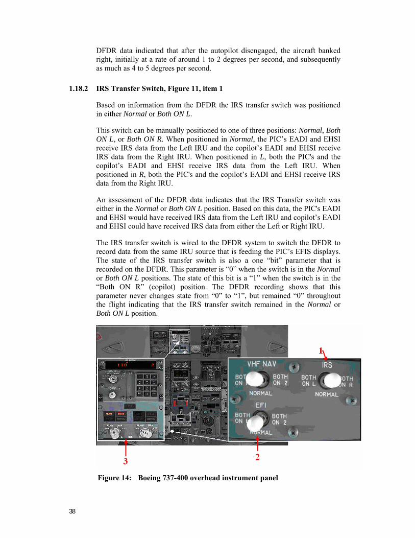
38
DFDR data indicated that after the autopilot disengaged, the aircraft banked right, initially at a rate of around 1 to 2 degrees per second, and subsequently as much as 4 to 5 degrees per second.
1.18.2 IRS Transfer Switch, Figure 11, item 1
Based on information from the DFDR the IRS transfer switch was positioned in either Normal or Both ON L.
This switch can be manually positioned to one of three positions: Normal, Both ON L, or Both ON R. When positioned in Normal, the PIC’s EADI and EHSI receive IRS data from the Left IRU and the copilot’s EADI and EHSI receive IRS data from the Right IRU. When positioned in L, both the PIC's and the copilot’s EADI and EHSI receive IRS data from the Left IRU. When positioned in R, both the PIC's and the copilot’s EADI and EHSI receive IRS data from the Right IRU.
An assessment of the DFDR data indicates that the IRS Transfer switch was either in the Normal or Both ON L position. Based on this data, the PIC's EADI and EHSI would have received IRS data from the Left IRU and copilot’s EADI and EHSI could have received IRS data from either the Left or Right IRU.
The IRS transfer switch is wired to the DFDR system to switch the DFDR to record data from the same IRU source that is feeding the PIC’s EFIS displays. The state of the IRS transfer switch is also a one “bit” parameter that is recorded on the DFDR. This parameter is “0” when the switch is in the Normal or Both ON L positions. The state of this bit is a “1” when the switch is in the “Both ON R” (copilot) position. The DFDR recording shows that this parameter never changes state from “0” to “1”, but remained “0” throughout the flight indicating that the IRS transfer switch remained in the Normal or Both ON L position.
Figure 14: Boeing 737-400 overhead instrument panel
39
Switching recorded during previous flights indicates the DFDR was recording a change in switch state and that the DFDR was switching its source of IRU inputs (verified by step changes in LAT/LONG data).
1.18.3 Electronic Flight Instrument (EFI) Transfer Switch, Figure 11, Item 2
Based on information from the FDR, the EFI transfer switch was positioned in the Normal or in the Both ON 1 (PIC) position.
This switch can be manually positioned to one of three positions: Normal, Both ON 1, or Both ON 2. When positioned in Normal, the PIC's EADI and EHSI displays are generated from the number-1 Symbol Generator, and the copilot’s EADI and EHSI displays are generated from the number-2 Symbol Generator. When positioned in Both on 1, both the PIC's and the copilot’s EADI and EHSI displays are generated from the number-1 Symbol Generator. When positioned in Both ON 2, both the PIC's and the copilot’s EADI and EHSI displays are generated from the number-2 Symbol Generator.
The EFI transfer switch is wired to the DFDR system to switch the DFDR to record data from the same EFIS Symbol Generator source that is feeding the PIC’s displays. The state of the EFIS transfer switch is also a one “bit” parameter that is recorded on the DFDR. Therefore, the state of this bit is a “0” when the switch is in the “Normal” or in the Both ON 1 (PIC) positions. The state of this bit is a “1” when the switch is in the Both ON 2 (copilot) position
Recorded data showed that on one of the earlier flights, this switch was changed to the Both On 2 position and discontinuities in the DFDR IRU data that was recorded from the EFIS buses, indicated that the other source was selected. This confirmed that the switch, and the recording of its position, was working as intended during that previous flight. Recorded data showed that for all other flights, the switch was left in the Normal or Both ON 1 (PIC) position.
1.18.4 Mode Selector Unit (MSU)18, Figure 11, item 3
Based on information from the CVR, one of the flight crew re-positioned the right IRU Mode Selector rotary switch or IRS Mode Selector from navigation NAV Mode to attitude ATT Mode.
The MSU is located on the aft overhead panel and is used to select the operating mode for each IRS. Indicator lights on the MSU show status of each IRS. The action of moving an IRS Mode Selector switch from navigation NAV Mode to attitude ATT Mode during cruise flight will cause all IRS attitude and heading data (for the respective IRU) to become no computed data (NCD), all Navigation parameters will be Failure Warning (FW) for a minimum of 30 seconds, and the autopilot will disengage. With pitch and roll data being NCD, the Symbol Generator (SG) will remove the horizontal lines, pitch lines, roll pointer and sky/ground shading from the (EADI). Flight path angle, Acceleration, Pitch Limit display and Traffic Alert and Collision Avoidance
18 See also Appendix E.
40
System (TCAS) Resolution Advisory (RA) commands are also removed.
During this 30 second transition to attitude Mode, the ALIGN light on the Mode Selector Unit (MSU) illuminates. The 737 Flight Crew Operations Manual (FCOM) instructs the flight crew to fly straight and level and unaccelerated flight after selection of ATT (Attitude) Mode. After 30 seconds, basic pitch and roll attitude parameters become valid, however magnetic heading will remain NCD until manually entered by the flight crew. Once pitch, roll and heading data become valid, the Inertial System Display Unit (ISDU) will display Malfunction Code 9. It is a code for the flight crew to enter magnetic heading using the ISDU or Flight Management Computer (FMC) via the Control Display Unit (CDU). Once magnetic heading is entered, the magnetic heading Sign Status Matrix (SSM) is set to Valid/Normal, but navigation parameters (latitude, longitude, groundspeed, drift, etc.) will be FW (Failure Warn/Invalid). Update to heading will be accepted at any time during the attitude mode, after the successful completion of attitude mode alignment process, which is approx 30 seconds.
The CVR recorded a crew comment about selecting attitude on the IRS Mode Selector Unit. Directly after the comment, the autopilot disengage warning tone sounded for 4 seconds and the DFDR indicated that the ailerons centered and the aircraft began rolling to the right, because the aircraft was out of trim by a small amount.
Based on the recorded yaw rate, the right (number-2) IRU would not have completed the short alignment (30 seconds). Thus, the right IRU data remained NCD and the copilot’s EADI and EHSI would not have displayed any attitude or heading data. DFDR data indicated that the IRS Transfer switch was in Normal or Both ON L position, and the EFI source selector switch was in the Normal or Both ON 1 position.
Therefore, based on the DFDR data and the bank angle alert from the CVR, the PIC’s EADI and EHSI received IRS data from the left IRU and the IRU data remained valid. The right IRS being placed in ATT (attitude) mode would not have affected the PIC's EADI and EHSI displays.
1.18.5 Autopilot Disengage
Based on information from the DFDR and the CVR, the autopilot automatically disengaged when the crew positioned the right IRS Mode Selector from navigation NAV mode to attitude ATT mode.
Normally each autopilot Flight Control Computer (FCC) utilizes the on-side IRU for Pitch data and the off-side IRU for Roll data.19 When one of the IRUs enters ATT Mode from NAV Mode (IRU attitude data going NCD) it will cause the autopilot to disengage. The DFDR recording indicated that the “A” channel autopilot was engaged until the right IRS Mode Selector was positioned from the NAV Mode to the ATT mode.
19 There are two Flight Control Computers (FCC). FCC A and B. When using autopilot A, FCC A will
use pitch data from the left IRU and roll data from the right IRU.
41
1.18.6 Navigation System Description
The navigation systems include the flight management system (FMS); inertial reference system (IRS); radio navigation systems (ADF, DME, ILS, marker beacons, and VOR); transponder; and weather radar.
The FMS is comprised of the following components:
• Flight management computer system (FMCS). • Autopilot/flight director system (AFDS). • Autothrottle (A/T). • Inertial reference systems (IRS).
Each of these components is an independent system, and each can be used independently or in various combinations. The term FMS refers to the concept of joining these independent components together into one integrated system, which provides continuous automatic navigation, guidance, and performance management.
The integrated FMS provides centralized flight deck control of the aircraft’s flight path and performance parameters. The flight management computer, or FMC, is the heart of the system, performing navigational and performance computations and providing control and guidance commands. The primary flight deck controls are the AFDS MCP, two control display units (CDUs), and two electronic flight instrument system (EFIS) control panels. The primary displays are the CDUs, electronic attitude director indicator (EADI), electronic horizontal situation indicator (EHSI), and thrust mode display.
The FMC uses crew entered flight plan information, aircraft systems data, and data from the FMC navigation database and performance database to calculate aircraft present position, and pitch, roll, and thrust commands required to fly an optimum flight profile. The FMC sends these commands to the autothrottle, autopilot, and flight director.
1.18.7 Inertial System
The inertial system computes aircraft position, ground speed, and attitude data for the flight instruments, flight management system, autoflight system, and other systems. The major components of the inertial system are the IRUs, an inertial system display unit (ISDU), IRS mode selector unit (MSU), and an IRS transfer switch.
Each IRU has three sets of laser gyros and accelerometers. The IRUs are the aircraft’s sole source of attitude and heading information, except for the standby attitude indicator and standby magnetic compass. In their normal navigation mode, the IRUs provide attitude, true and magnetic heading, acceleration, vertical speed, ground speed, track, present position, and wind data to appropriate aircraft systems. IRU outputs are independent of external navigation aids.
42
1.18.8 IRS Alignment
An IRS must be aligned and initialized with aircraft’s present position before it can enter the navigation (NAV) mode. The present position is normally entered through the FMC CDU. The aircraft must remain stationary during alignment. Alignment is normally completed prior to taxiing.
1.18.9 Loss of Alignment
If alignment is lost in flight, the navigation mode (including present position and ground speed outputs) becomes inoperative for the remainder of the flight. However, selecting ATT allows the attitude mode to be used to re-level the system and provide an attitude reference. The attitude mode requires approximately 30 seconds of straight and level, un-accelerated flight to complete re-leveling. Some attitude errors may occur during acceleration, but will be slowly removed after acceleration stops.
The attitude mode can also provide heading information, but to establish compass synchronization the crew must manually enter the initial magnetic heading. Drift of up to 15 degrees per hour can occur in the IRS heading. Therefore, when in ATT mode, an operating compass system must be periodically cross–checked and an updated magnetic heading entered in the IRS, as required.
1.18.10 Navigation System Assessment ― IRUs
PK-KKW was equipped with two Honeywell IRUs; One IRU was part number HG1050AD05, and serial number 2296, the other IRU had part number HG1050AD10, and serial number 7889.
A review of maintenance log entries for PK-KKW between 20 November 2006 and 31 December 2006, revealed 16 entries that specifically referenced IRS component anomalies. The data contained within the maintenance logs indicates that “IRU #1 (Left) was cross changed with IRU #2 (Right)” on 17 December 2006 and that both IRUs were “repositioned” on 27 December 2006. Based on an assessment of the data, the “reposition” is the same as a “re-rack” action, e.g., the equipment is removed and re-installed at the same location in the rack. Therefore, the maintenance action taken on 17 December 2006, indicates that the positions of IRU number 1 and IRU number 2 were swapped. The maintenance logs did not indicate another swap of the two IRUs after 17 December 2006.
Information contained within the maintenance logs indicates that before 17 December, the right IRU (S/N YY)20 experienced a high drift rate that resulted in relatively high (7NM to 20 nm) position deviation errors.
20 For the purposes of this report, S/N XX is the IRU that was installed on the Left side or No.1 position
prior to 17 Dec. S/N YY is the IRU that was installed on the Right side or No. 2 position prior to 17 Dec. Although the serial numbers of the two units are known, the positions on the aircraft of the two units at the time of the accident are unknown.
43
After 17 December 2006, the right IRU (S/N YY) was installed on the left side and the pilot reporting of position deviation followed, as can be seen by the maintenance write-ups on 22 and 27 December 2006:
• Deviation up to 20 nm when climbing and cruise (22 December).
• L IRS 45 nm, R IRS 1-2 nm (27 December).
Most of the maintenance actions involved cleaning the connectors, re-racking, and ground test. There was no evidence that maintenance actions during this period involved replacement of an IRU (other applicable IRUs), or checking the aircraft wiring for anomalies discussed above.
Some of the maintenance entries for the IRS were related to position errors, but none were written about residual groundspeed errors, which is one of the criteria for IRU removal (15 knots for 2 consecutive flights, or 21 knots for one flight – Ref: AMM 34-28-01, IRS Accuracy Criteria, A. Residual Groundspeed Error). The DFDR data showed that there were some residual groundspeed errors in conjunction with the pilot report (PIREP), which should have warranted replacement of the IRU.
1.18.11 Flight Management System
The only FMC data available from the DFDR is the “Distance To Go (DTG)” with a 1 nm resolution; it is recorded once every 64 seconds. Most of the FMC operation must be inferred from other parameters and known FMC design characteristics, with various levels of engineering judgment and confidence.
1.18.12 Aircraft on Ground
Both Inertial Reference Units (IRUs) were probably aligned using an Airport Reference Point (ARP). When a position offset (derived from ARP and Park Pos 11) is applied to the IRU position, the resulting taxi path matches the taxiways at the airport. The alignment position introduces a relatively small IRU position error and would have little impact on the IRU velocity accuracy.
Typically, the IRU will be aligned using the coordinates for the gate (parking position) or the coordinates for the airport reference point (ARP). At the origin airport, Djuanda Airport, Surabaya, the gates are on the north side of the runway, while the ARP is on the south side. These two positions are about 0.5nm apart.
Assuming the IRU was aligned using the parked position, then at the start of the DFDR data (engine start) the IRU position was already about 0.7nm from the parked position. Using the UTC from the DFDR, the aircraft had engines off for 47 minutes. Given a 10 minute align time, the IRUs were in NAV mode less than 40 minutes at the time of the accident. To achieve a 0.7nm error in 40 minutes with just an acceleration error, the IRU acceleration would be 0.0015 ft/sec2, with a resulting groundspeed of at least 2 knots at the end of 40 minutes. Since the recorded groundspeed is 1 knot with the aircraft apparently stationary (no heading change for 30 seconds), the assumption of aligning at the gate position is inconsistent with the recorded data.
44
The FMC selects the left IRU as the default IRU while on the ground, once both IRUs are operating in NAV mode. The DFDR data for this flight included IRU position and groundspeed from IRU-L (number-1 IRU).
1.18.13 Aircraft - Airborne
Based upon the difference between the IRU position and a position derived from the DME data, the IRU position to radio position difference was 5 nm after being airborne for 10 minutes (06:10:40). The IRU-Radio velocity difference was > 50kts after being airborne for 12 minutes (06:12:40).
Given the FMC’s default selection of the left IRU while on the ground and the large left IRU velocity errors shortly after takeoff, it is probable that the FMC’s velocity divergence test determined that the IRU-R was the erroneous IRU. This would preclude the FMC’s position difference test (IRU-Radio position > 4nm) from causing the FMC selected IRU to switch to IRU-R.
The FMC position will track the IRU position (or an offset if a runway position update was performed), until radio updates occur. Since the FMC position is not recorded, the FMC position updates must be inferred from the radio tuning history.
Evaluation of the DTG parameter indicated the following about the active FMC flight plan. These are based upon the known locations in the database and/or en-route chart.
Time (UTC) Probable Active Waypoint
Start to 06:10 FANDO 06:10 to 06:15 KASOL 06:15 to 06:16 DIOLA 06:16 to 06:22 MKS, Abeam MKS or waypoint S 03°40.8´ E 118° 35.2´ 06:22 to 06:41 OVINA 06:41 to 06:56 Abeam MKS or waypoint S 03° 40.8´ E 118° 35.2´ 06:56 to End DIOLA
The LNAV control flew at a nearly constant course for the latter part of each of the segments when LNAV was engaged, implying the aircraft was on-track or was on fixed intercept course (capture path). The position and velocity data from the IRU and that derived from radio data imply that LNAV control was based upon a position and velocity different from either of these in the middle part of the flight. This is probable, since the FMC will extrapolate its derived corrections from the last radio update. Since the LNAV roll control is a combination of position and velocity, a unique solution for the FMC position and track is not possible.
The peak magnitude of the left IRS errors (Peak Position: greater than 50nm, Peak Velocity: greater than 80kts) far exceeds the navigation specification for the IRS, and leads to difficulties with the FMC navigation function.
45
The FMC’s position smoothing function incorporates a rate limit on the North and East position difference between its internal position derived from radio data and its selected IRU. The rate limit is 2nm/minute in the terminal environment and 0.5nm/minute en route for each of the North and East axes.
If the velocity error in the selected IRU exceeds the rate limit, the velocity difference in excess of the rate limit value will integrate into a position difference. This effect was probably occurring during the flight.
1.18.14 Pilots’ Flight Track Information
The aircraft was heading 070° at about 35,000 feet (FL350). Even though they were experiencing serious IRS problems and navigation difficulties that they could not resolve, no distress calls were radioed by the pilots. They were several miles off course to the north of their assigned routing and were attempting to fly direct to their destination via radar vectors. They mentioned an extremely strong crosswind of 74 knots from their left.
At 06:55:51.5 the PIC instructed the copilot to: Try to confirm position. Confirm on what radial 124 DME. At 06:55:58.0, about 4 minutes before radar contact with the aircraft was lost, the copilot contacted UPG ATC and asked Ok, we uh, confirm position from your radar sir. At 06:56:04.3 the controller responded Ujung, Adam 574, position is 125 miles mike kilo sierra, crossing radial 307 mike kilo sierra. (The aircraft’s position was 125 miles from the Makassar DME and 307 degrees magnetic (west northwest) from the Makassar VOR.) The weather conditions along the W-32 route, and the ATC cleared track from KASOL to DIOLA, generally consisted of convective clouds conducive to the formation of icing, hail, lightning, and potentially severe or greater convectively induced turbulence.
The CVR and the ATC transcript indicated that the pilots did not ask the controller for a diversion from their cleared track due to weather.
At the time, other aircraft south bound to Surabaya on route W-32 were asking for diversions to the east due to weather.
About 14 minutes before the divergence from controlled flight, the aircraft encountered unfavourable and deteriorating weather that the crew termed bad weather.
A tape recording from the Air Traffic Control radar of Adam 574 was evaluated at the Thales facility (radar manufacturer) in Paris. The purpose was to determine the changes of heading and speed, as well as the altitude during the last 3 minutes before the aircraft disappeared from the Makassar Advanced Air Traffic Services (MAATS) radar display.
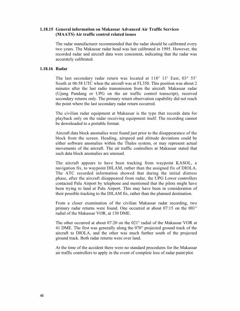
46
1.18.15 General information on Makassar Advanced Air Traffic Services (MAATS) Air traffic control related issues
The radar manufacturer recommended that the radar should be calibrated every two years. The Makassar radar head was last calibrated in 1995. However, the recorded radar and aircraft data were consistent, indicating that the radar was accurately calibrated.
1.18.16 Radar
The last secondary radar return was located at 118° 13’ East, 03° 55’ South at 06:58 UTC when the aircraft was at FL350. This position was about 2 minutes after the last radio transmission from the aircraft. Makassar radar (Ujung Pandang or UPG on the air traffic control transcript), received secondary returns only. The primary return observation capability did not reach the point where the last secondary radar return occurred.
The civilian radar equipment at Makassar is the type that records data for playback only on the radar receiving equipment itself. The recording cannot be downloaded to a portable format.
Aircraft data block anomalies were found just prior to the disappearance of the block from the screen. Heading, airspeed and altitude deviations could be either software anomalies within the Thales system, or may represent actual movements of the aircraft. The air traffic controllers at Makassar stated that such data block anomalies are unusual.
The aircraft appears to have been tracking from waypoint KASOL, a navigation fix, to waypoint DILAM, rather than the assigned fix of DIOLA. The ATC recorded information showed that during the initial distress phase, after the aircraft disappeared from radar, the UPG Lower controllers contacted Palu Airport by telephone and mentioned that the pilots might have been trying to land at Palu Airport. This may have been in consideration of their possible tracking to the DILAM fix, rather than the planned destination.
From a closer examination of the civilian Makassar radar recording, two primary radar returns were found. One occurred at about 07:15 on the 001° radial of the Makassar VOR, at 130 DME.
The other occurred at about 07:20 on the 021° radial of the Makassar VOR at 41 DME. The first was generally along the 070° projected ground track of the aircraft to DIOLA, and the other was much further south of the projected ground track. Both radar returns were over land.
At the time of the accident there were no standard procedures for the Makassar air traffic controllers to apply in the event of complete loss of radar paint/plot.
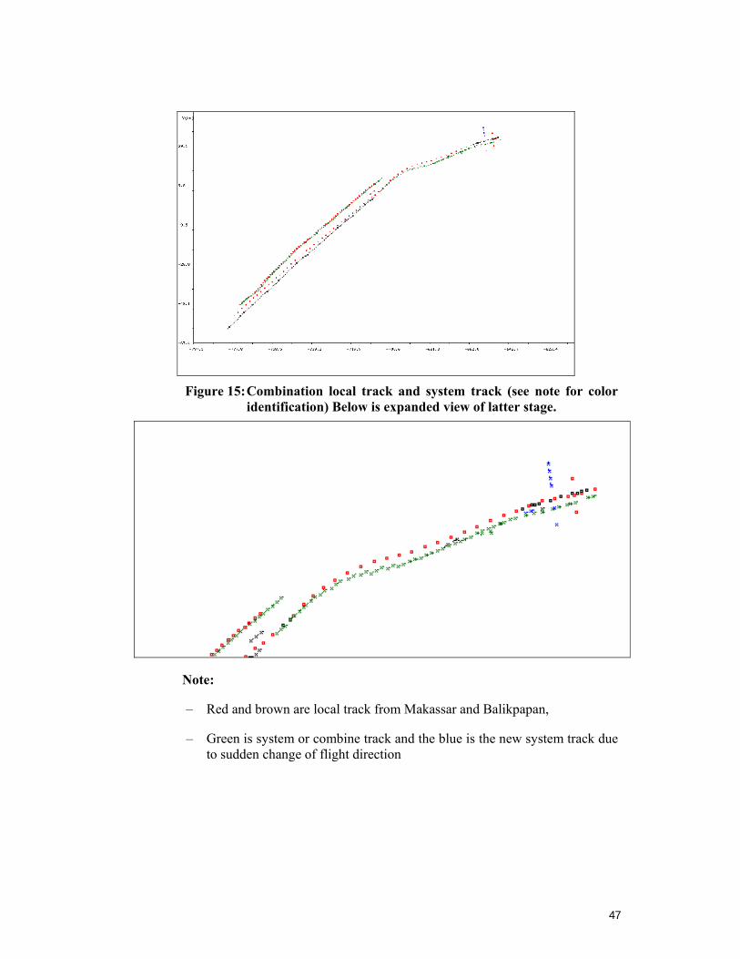
47
Figure 15: Combination local track and system track (see note for color
identification) Below is expanded view of latter stage.
Note:
– Red and brown are local track from Makassar and Balikpapan,
– Green is system or combine track and the blue is the new system track due to sudden change of flight direction
48
1.18.17 Human Factors
The pilots of AdamAir 574 appeared to be over reliant on the on-board navigation system (IRS). When they realized they were having problems with one of the IRS, they were twice given position information by Ujung Control about radial and distance. They believed that the number-2 IRS was malfunctioning. However, the problem with the number-2 IRS did not trigger the illumination of a fault light as expected by the pilots; stated in the QRH. They subsequently decided to use the IRS fault procedure in the QRH even though the fault light had not illuminated. However, after moving the IRS Mode Selector switch to ATT, they did not comply with the QRH requirement to fly the aircraft straight and level at a constant airspeed for 30 seconds in accordance with the QRH Chapter 11.
The pilots tried to directly input the heading after they changed the IRS mode selector to attitude. There was no evidence of an attempted recovery action by the pilots until the aircraft had rolled right and exceeded 35 degrees right bank angle and the GPWS sounded the bank angle alert at 35 degrees of right bank. At that time, they may have been affected by spatial disorientation.
The PIC did not clearly articulate an appropriate distribution of tasks to be performed by the crew when there appeared to be a significant IRS problem. As a result, both pilots became distracted by trouble shooting the IRS malfunction, and did not control or monitor the flight path of the aircraft. Inappropriate upset recovery procedures were used, which allowed the situation to deteriorate until structural failure occurred and control of the aircraft was no longer possible.
Even though the right number-2 IRS was switched to ATTitude, the PIC’s flight instruments should not have been affected, including the Standby ADI, and therefore available instruments to ensure the safe operation of the aircraft. For more detail on crew resource management, situational awareness and associated sensory illusions see Appendix D.
This accident is similar to several other recent accidents that have involved flight crew spatial disorientation and loss of control, including:
• 3 May 2006: Armavia Airlines flight RNV 967, an Airbus A-320 near Sochi, Russia.
• 3 January 2004: Flash Airlines flight 604, a Boeing B-737-300 near Sharm el-Sheikh, Egypt.
• 23 August 2000: Gulf Air flight 072, an Airbus A-320, near Muharraq, Bahrain.
• 10 January 2000: Crossair flight 498, a Saab 340B, near Zurich, Switzerland.
Although the circumstances of each of these accidents differs in certain respects, in each, the flying pilot was distracted from monitoring the primary flight instruments by operational matters, and then either made inadvertent control inputs in response to vestibular illusions, or allowed the aircraft to roll uncontrolled to an undesired attitude. In the case of Armavia Airlines, Flash Airlines, and Crossair, the flying pilot was alerted to the change in aircraft attitude, but had difficulty determining the appropriate corrective action, and instead made control inputs that worsened the situation.
49
2. ANALYSIS Pilots operating the Boeing 737-4Q8, registered PK-KKW, had experienced repeated/recurring problems related to the aircraft’s Inertial Reference System (IRS), mostly the left (number-1) system, over more than 3 months prior to the accident. During the 3-month period prior to the accident, the number of recurring defects totaled: October 55, November 50, and December 49. The maintenance actions to rectify the problems were mainly: re-racking, swapping, contact cleaning, and relay replacement.
On 1 January 2007, during cruise at FL 350 between Surabaya (SUB), East Java and Manado (MDC), Sulawesi, the pilots experienced an Inertial Reference System (IRS) anomaly.
The investigation could not determine when or if the crew conducted IRU alignment procedures. If the crew did not start the IRU alignment coincident with engine shutdown, but delayed the IRU alignment until the start of a normal preflight, then the evidence is stronger for alignment using the Airport Reference Point (ARP) position rather than the parked position.
If the IRU groundspeed error was 2 or more knots, then the aircraft’s taxi path, as derived from the recorded position, would not remain within the confines of the taxiway and runway.
The resolution of Distance To Go (DTG) is not sufficient to determine if a runway position update was performed prior to takeoff. The only conclusive observation is that the FMC position will be within 1nm of the IRU position at liftoff.
During cruise, the pilot in command (PIC) and copilot became preoccupied with the aircraft’s Inertial Reference System (IRS) and associated failures of the flight and navigation instruments.
The pilots devoted their attention to resolving the apparent anomalies with the IRS for up to 28 minutes prior to switching the number-2 IRS Mode Selector Unit to ATT (Attitude). Initially, they were concerned that one of the Inertial Reference Unit’s (IRU) had failed, and they attempted to identify the problem.
Subsequently, the pilots also expressed concerns about the weather and their ability to navigate accurately. Both pilots became fully engrossed with identifying the problem and attempts at corrective actions for at least the last 13 minutes of the flight, with minimal regard to other flight requirements.
The DFDR showed that the aircraft was in cruise with the autopilot engaged at FL 350. The autopilot was holding 5 degrees left aileron to maintain wings level flight. Following the crew’s selection of the IRS Mode Selector Unit to Attitude mode, the autopilot disengaged.
When ATT (Attitude) was selected in the number-2 IRS Mode Selector Unit, it resulted in the autopilot disengaging. The effect on the copilot’s electronic attitude display indicator (EADI) of switching from NAV to ATT was that the following displays were lost:
50
• Roll indication.
• Horizon scale.
• Pitch scale.
• Sky/ground shading.
Flight path angle, Acceleration, Pitch Limit display and Traffic Collision Avoidance System (TCAS) Resolution Advisory (RA) commands are also removed.
With the autopilot disengaged, the control wheel (aileron) centered and the aircraft began a slow roll to the right. Although the roll rate was momentarily arrested several times, the pilot did not begin to recover the roll attitude until the aircraft had reached a bank angle of 100 degrees, with the pitch attitude approaching 60 degrees aircraft nose down. At that point the aircraft had already accelerated past Mmo (0.82) and was reaching dive Mach number of 0.89. The overspeed warning activated at Mach 0.82. After the autopilot disengaged and the aircraft exceeded 30 degrees right bank, the pilots appeared to have become spatially disoriented.
The DFDR revealed that after the aircraft reached a dive Mach number of 0.89, the pilot began to roll the aircraft towards wings level, using a bank angle of less than 20 degrees (aileron). During this roll, the pilot pulled nose-up elevator in excess of 2gs of force. The g forces eventually reached 3.5gs as the Mach number reached a maximum of 0.926. The 3.5g force and Mach 0.926 airspeed are beyond the designed limitations of the aircraft. Federal Aviation Regulation (FAR) 25.333 covers maneuver envelopes for structural design. FAR 25.333 shows the v-vs-n maneuvering envelope. At dive speeds, structures are required to maintain integrity 0 to 2.5g's.
The recorded airspeed exceeded Vdive (400 kcas), and reached a maximum of approximately 490 kcas just prior to the end of recording. At an altitude of approximately 12,000 feet, the normal load factor suddenly and rapidly reversed from around positive 3.5g to negative 2.8g.
The Boeing analysis suggested that:
This sudden change in load factor is an indication that the airplane has suffered a significant structural failure. The condition of 3.5g’s at 495 knots is well beyond the certified flight maneuvering envelope for generating loads for structural design and outside the envelope for being flutter free’. …the 737 Flight Crew Training Manual provides training technique for upset recovery. ...using these techniques for the applicable situation [the accident flight] would have led to an expected recovery, had it been performed within the airplane’s flight envelope. Using the [Boeing] engineering simulation, a recovery was initiated at Mmo by leveling the wings first, then pulling [nose up elevator]. This simulation showed that the airplane is capable of recovering with a minimum amount of overspeed for this scenario.
51
Although one of the pilots silenced the autopilot aural warning, it is apparent that the pilots did not act appropriately when the autopilot had disengaged, and did not respond to the subsequent bank angle and altitude deviation alerts. After the autopilot disengaged, the aircraft rolled with slight acceleration. This slight acceleration was likely to be imperceptible to the pilots. After the autopilot disengaged, the pilots’ focussed their attention on trouble shooting of the IRS and the navigation instruments; attempting to identify the problems and take corrective actions. There was no evidence that they were appropriately controlling the aircraft, even after the BANK ANGLE, BANK ANGLE, BANK ANGLE, BANK ANGLE alert sounded as the aircraft rolled right and exceeded 35 degrees of bank.
The pilots did not have sufficient knowledge of the aircraft system to quickly and appropriately troubleshoot the IRS problem they were facing. Their actions to rectify the problem resulted in a number of decision errors.
It is likely that, in part, this accident was the result of the failure of the pilots to monitor the flight instruments, particularly during the final 2 minutes of the flight, and to detect an unexpected descent soon enough to prevent loss of control and impact with the water. Preoccupation with an apparent malfunction of the IRS distracted both pilots’ attention from the flight instruments and allowed the increasing descent and bank angle to go unnoticed. It is evident that the pilots allowed their attention to be channelized, and they lost situational awareness, and became spatially disoriented at a critical phase of the flight. They were not aware of the changes to the aircraft attitude.
The investigation considered the possibility of the Standby Attitude Indicator erecting to a false vertical, thereby providing erroneous attitude indication during the aircraft roll event following the autopilot disengagement.
FDR data indicated that after the autopilot disengaged, the aircraft banked right, initially around 1 to 2 degrees per second, and subsequently as much as 4 to 5 degrees per second. At the roll rate indicated, the erection cut off should have been in effect, and the standby ADI would not have erected to a false vertical. Therefore, it is considered that the standby ADI provided attitude indication corresponding to the aircraft attitude.
The aircraft had entered cloud and unfavorable weather 14 minutes prior to the upset. However, the investigation was not able to determine if the pilots were flying in instrument meteorological conditions at the time of the upset. It is likely that they were in marginal visual meteorological conditions.
It is apparent that the pilots did not anticipate that the autopilot would disengage when they changed the IRS Mode Selector Unit to Attitude. Moreover, the PIC and copilot were not appropriately monitoring the flight instruments during the trouble shooting, and they were oblivious to the escalating adverse aircraft state. They also disregarded a number of initial alerts, warnings, and changes to displays.
From the copilot’s statement, what’s the heading Cap? 079 ya, in response to the PIC’s instruction to input the heading, it is evident that at least the copilot looked at the heading instrument. It appears that the PIC may not have looked at the EADI bank indicator/artificial horizon, or the standby artificial horizon.
52
There is also no evidence that either of the pilots cross checked the flight instruments. The PIC may have perceived a turn sensation because he commanded the copilot don’t turn it, this is our heading.
From about 06:58:40 the aircraft had rolled to a right bank angle of 100 degrees and was approaching 60 degree nose down. The aircraft continued to descend, turn, and roll. The crew action of pulling back on the column (increase elevator) would have exacerbated the problem. After that, the aircraft rolled again to the right in a 30 degree right bank, 44 degree pitch nose down, and heading 335 degrees. There was no further recorded data. It is evident that when the pilots realized their critical situation, they attempted to effect recovery by using inappropriate control inputs. Boeing upset recovery procedure requires roll to wings level before applying nose-up elevator. The DFDR showed that this procedure was not followed by the crew.
Flight recorder data indicated that a significant aerodynamic structural failure of the empennage occurred when the aircraft was at a speed of Mach 0.926 and the flight load suddenly and rapidly reversed from 3.5g to negative 2.8g. This g force and airspeed are beyond the design limitations of the aircraft. A thump, thump sound, which coincided with the time of the sudden flight load reversal, was evident on the CVR about 20 seconds from the end of the recorded data. The thump, thump sound on the CVR was verified by spectrum analysis and determined to be typical of a structural failure. It is likely that the empennage sustained a significant structural failure during this sudden and rapid flight load reversal. At the time of the thump, thump sound, the aircraft was in a critically uncontrollable state.
The last recorded valid pressure altitude data point was at 9,920 feet. The DFDR continued to record other valid parameters until it stopped completely at about 9,000 feet. It is likely that the flight recorders ceased to function properly, due to the disruption of the electrical circuitry associated with the recorders, and resulting from the structural failure in the empennage area of the aircraft.
The flight recorder analysts confirmed that the data from the DFDR was valid until 9,920 feet. Boeing specialists stated that:
There is no reason to believe that the data recorded on the DFDR was invalid, except for a few data drop outs. Airspeed accuracy will decrease as airspeed approaches and exceeds dive Mach number (Mdive=0.89). This error in airspeed will vary from airframe to airframe.
Based upon the frequency selection for the VHF-L and VHF-R, the radios were auto tuned early in the flight. The time history of the auto-tuning provided an indication of whether the FMC was radio updating. If a frequency is tuned for more than 20-25 seconds (40-50 seconds in agility DME), it is probable the FMC updated from the navaid associated with that frequency.
53
Based upon the tuning history:
1. The FMC was probably VOR-DME updating over three distinct 30 second time periods while within 25nm of SBR 113.40 (06:02:37 to 06:05:59).
2. The FMC was probably DME-DME updating in two distinct intervals using MTM 114.50 and IWY 114.80 (06:14:32 to 06:18:13). The first was agility tuning, while the second was normal tuning using both radios.
3. DME auto-tuning at ranges more than 130nm to the ground station is consistent with the Update 5 FMC SW (168925-06-01)
If the right IRS was operating within specification, the FMC probably displayed a VERIFY POSITION message within the first 20 minutes of the flight due to the left IRS and right IRS positions differing by more than 10nm. The CVR recorded the last 30 minutes of the flight. Accordingly recorded CVR data commenced at 06:28:30. There was no reference to verify position on the CVR until 06:41:55 when the Copilot asked is it verify position? However there was no reference on the CVR to a FMC VERIFY POSITION message.
The large magnitude wind recorded on the DFDR and discussed by the crew on the recorded CVR data are consistent with the large velocity errors in the IRS.
The AdamAir Continuous Airworthiness Maintenance Program approved by DGCA was supported by a Reliability Control Program (RCP). However, the RCP did not cover component reliability. There was no evidence that AdamAir included component reliability in their RCP to ensure the effectiveness of the airworthiness of the aircraft components for the AdamAir fleet. There was also no evidence of AdamAir’s maintenance management controlling the repetitive defects on their fleet prior to the accident resulting in defects not being appropriately rectified.
The repeated/recurring IRS problems created a working environment that tolerated continued operation of the aircraft with known IRS faults. This tolerance was evident in both the management of flight operations and also maintenance engineering.
The airline’s management did not anticipate the need for sufficient spare parts to ensure the safe operation. The management did not have an adequate safety policy to provide training programs for operation and maintenance personnel. The fact that AdamAir was still having fleetwide recurring IRS/IRU defects 11 months after the accident (November 2007), clearly shows that the engineering supervision and oversight changes that were put in place after the accident, to resolve the recurring problems, were not effective.
The crew became distracted by trouble shooting the IRS malfunction, to the detriment of safely operating the aircraft. They did not follow the QRH which required that they maintain straight and level constant airspeed flight until attitude displays recover on the Electronic Attitude Display Instrument.
54
The dangers of this fact have been highlighted in accidents such as the Eastern Airlines Lockheed L-1011, Miami, Florida on 29 December 1972 that crashed when the crew became preoccupied with a landing gear warning light.21
At the time of the accident involving PK-KKW, AdamAir did not provide their pilots with aircraft upset recovery training. There was no evidence that either pilot had completed a course of training, or been checked in a simulator, for proficiency in aircraft upset recovery, including spatial disorientation and situational awareness.
The wreckage debris was located nine days after the accident and the approximate locations of both flight recorders were logged 21 days after the accident. The salvage operation to recover the flight recorders was not commenced until 24 August 2007, almost eight months after the accident. Both flight recorders were relocated on the bottom of the ocean and recovered on 27 and 28 August 2007. In hindsight, the investigation would not have been able to determine what the true circumstances of the accident were without the information provided by flight recorders. And, the near eight-month delay between the date of the accident and the recovery of the flight recorders was unacceptable. Given ocean bottom currents and the constant silting that was occurring, it was very possible that the recorders would have never been found. Further, although the recorders were found, their long term exposure to the ocean environment introduced the possibility that, when found, the boxes would be damaged beyond the point of producing useful data.
The last secondary radar return was located at 118° 13’ East, 03° 55’ South at 06:58 UTC when the aircraft was at FL350. This position was about 2 minutes after the last radio transmission from the aircraft. Makassar radar (Ujung Pandang or UPG on the air traffic control transcript), received secondary returns only. The primary return observation capability did not reach the point where the last secondary radar return occurred.
The air traffic controllers were concerned about the safety of the aircraft from 07:09, when they were unable to establish contact. Other aircraft operating in the area were asked to assist the controllers making contact with PK-KKW by radio. Despite their concerns, the controllers did not declare an INCERFA (Uncertainty phase) until 08:15. An uncertainty phase is required to be declared when there is concern about the safety of an aircraft or its occupants when communication is not received, or the aircraft fails to arrive within 30 minutes of a prescribed time. An ALERFA (Alert phase) was not declared until 09:08. The alert phase is required to be declared when there is apprehension about the safety of an aircraft and its occupants when communication is not received or the aircraft fails to arrive within 60 minutes of a prescribed time.
Given the concerns expressed by the controllers about the safety of the aircraft from 07:09, an uncertainty phase and alert phase would have been expected to have been declared at 07:39 and 08:09 respectively. At the time of the accident there were no standard procedures for the Makassar air traffic controllers to apply in the event of complete loss of radar paint/plot.
21 NTSB AAR-73-14.
55
3. CONCLUSIONS 3.1 Findings22
3.1.1 Operations related issues
1) The pilots were appropriately licensed and qualified to operate the Boeing 737 series aircraft.
2) There was no evidence that the pilots were not medically fit.
3) The pilots complied with the Directorate General Civil Aviation (DGCA) and AdamAir flight and duty limitations.
4) The pilot in command (PIC) was the handling pilot and the copilot was the support/monitoring pilot.
5) The aircraft was being operated within the approved weight and balance limitations.
6) The pilots were faced with an Inertial Reference System (IRS) malfunction, which, with crew action, rendered the number-2 (right) EADI inoperative.
− The left (PIC) EADI and the Standby ADI for attitude and direction indication were available before and after the autopilot disengaged.
− The right (copilot) EADI lost roll indication, horizon, pitch scale, and sky/ground indications.
7) The pilots did not have sufficient knowledge of the aircraft system to quickly and appropriately troubleshoot the IRS problem they were facing. Their actions to rectify the problem resulted in a number of decision errors.
8) The pilots consulted the appropriate section of the aircraft’s Quick Reference Handbook (QRH) to attempt to resolve the IRS malfunction, however they did not maintain straight and level, constant airspeed flight after the IRS Mode Selector was switched to Attitude in accordance with the QRH.
9) The pilots selected Attitude in the IRS, which disengaged the autopilot. After the autopilot disengaged and the aircraft rolled right and exceeded 35 degrees right bank, the pilots appeared to have become spatially disoriented.
10) The PIC did not manage the task sharing. Crew resource management practices were not followed.
− The PIC had not completed CRM recurrent training since joining AdamAir as required.
− The copilot’s recurrent CRM training was not due until 4 May 2007.
22 The finding numbers in this chapter do not denote a level of importance.
56
11) Both pilots became engrossed with trouble shooting Inertial Reference System (IRS) anomalies for at least the last 13 minutes of the flight, with minimal regard to other flight requirements.
12) From about 06:58:40, with a right bank angle of 100 degrees and approaching 60 degrees nose down, the pilots realized their critical situation and attempted to effect recovery by using inappropriate control inputs.
13) A significant aerodynamic structural failure occurred at the time of the g force reversal; the time of the recording of the thump, thump sound. The thump, thump sound on the CVR was verified by spectrum analysis and determined to be typical of a structural failure.
14) There was no evidence of in-flight fire. The aircraft impacted the water at high speed and a steep descent angle and disintegrated on impact.
15) The AdamAir syllabus of training did not cover complete or partial IRS failure training.
16) The Flight Crew Operations Manual (FCOM) and the QRH used in AdamAir Boeing 737 aircraft had not been revised since the aircraft were delivered in December 2005. The revision number of the FCOM was B15/03Dec04. The revision number of the QRH was NC4/03Dec04.
− There was no evidence that document revision status was maintained for PK-KKW or other Boeing 737 aircraft in the AdamAir fleet.
17) The Boeing 737–300/400/500 FCOM held by AdamAir did not cover initial IRS training material.
18) There was no evidence that the pilots received training covering unexpected autopilot disengaging, and the knowledge and skills required for manual handling and using the standby instruments in the event of an IRS failure.
19) At the time of the accident AdamAir did not provide their pilots with IRS malfunction corrective action training in the simulator, nor did they provide aircraft upset recovery training or proficiency checks.
20) At the time of the accident the AdamAir organization structure included a Flight Standard Manager, but his listed duties did not include responsibility for the aircraft operations manuals.
3.1.2 Maintenance engineering related issues; AdamAir
1) Technical log (pilot reports) and PK-KKW maintenance records showed that between October and December 2006, there were 154 recurring defects, directly and indirectly related to the aircraft’s Inertial Reference System (IRS), mostly the left (number-1) system.
57
2) There was no evidence that the airline’s maintenance organization was trouble shooting IRS anomalies throughout the IRS system in accordance with the 737 Aircraft Maintenance Manual (AMM), other than re-racking and swapping IRU positions and associated components, resetting circuit breakers and cleaning connections when the faults became repetitive.
3) The DFDR data showed residual groundspeed errors in conjunction with the pilot report, which should have warranted IRU replacement.
3.1.3 Maintenance engineering related issues; Directorate General Civil Aviation
1) There was no evidence that prior to December 2006, DGCA was actively ensuring that AdamAir was rectifying the numerous IRS defects on the AdamAir Boeing 737 fleet.
2) There was no evidence that DGCA was aware that the AdamAir component reliability program did not assure the effectiveness of the airworthiness of the aircraft components for the AdamAir fleet.
3.1.4 Other findings
While not contributing to the accident, the investigation noted the following.
1) Fleetwide recurring IRS/IRU defects were still occurring as recent as November 2007. Engineering supervision and oversight changes that were put in place after the accident, to resolve the recurring problems, have not been effective.
2) Despite their concerns, the controllers did not declare an INCERFA (Uncertainty phase) until 08:15 when it could reasonably be expected to have been declared at 07:39. An ALERFA (Alert phase) was not declared until 09:08 when it could reasonably be expected to have been declared at 08:09.
3.2 Causes23
1) Flight crew coordination was less than effective. The PIC did not manage the task sharing; crew resource management practices were not followed.
2) The crew focused their attention on trouble shooting the Inertial Reference System (IRS) failure and neither pilot was flying the aircraft.
3) After the autopilot disengaged and the aircraft exceeded 30 degrees right bank, the pilots appeared to have become spatially disoriented.
4) The AdamAir syllabus of pilot training did not cover complete or partial IRS failure.
5) The pilots had not received training in aircraft upset recovery, including spatial disorientation.
23 The Cause and Other Causal Factor numbers in this chapter do not denote a level of importance.

58
3.2.1 Other Causal Factors
1) At the time of the accident, AdamAir had not resolved the airworthiness problems with the IRS that had been reoccurring on their Boeing 737 fleet for more than 3 months.
2) The AdamAir maintenance engineering supervision and oversight was not effective and did not ensure that repetitive defects were rectified.
59
4. SAFETY ACTION 4.1 Directorate General Civil Aviation
On 12 December 2007, the Directorate General Civil Aviation (DGCA) informed the National Transportation Safety Committee that DGCA issued a Safety Circular No. AU/5922/DSKU/EK/08/2007 on 23 November 2007 in response to the NTSC KNKT/07.01/08.0136, recommendation 5.4, dated on 8 October 2007.
The DGCA Circular stated that it is mandatory for every Operation and Maintenance Directorate within each Air Operator Certificate (AOC) holder to conduct the following as soon as possible:
a. To acquire and possess current (updated) version of all aircraft and manufacturer’s manuals for their fleet, including Aircraft Flight Manual (AFM), Flight Crew Operation Manual (FCOM), and Flight Crew Training Manual (FCTM). Those aforementioned manuals shall be distributed to flight crews within each operator upon availability of them.
b. To conduct FMS training (IRS/FMS) in an approved FMS Trainer.
c. To evaluate differences training matrix regarding different series within a type of aircraft operated by the operator.
d. To conduct failure training related to Automatic Flight Systems (AFS).
e. To conduct recurrent training for all flight crews in a form of Class Room training and LOFT (Line Oriented Flight Training) for a minimum of once a year.
f. To immediately conduct training, for Aircraft Maintenance Engineers, related to troubleshooting of all aircraft navigational systems operated by each operator.
g. Corrective action taken against complaints from flight crews, or rectification of any technical problems, shall be performed in accordance with any updated Maintenance Manual.
h. To ensure that any authorized Aircraft Maintenance Engineer performing troubleshooting is well-trained and qualified.
i. Initiate Maintenance Review Board (MRB) for any repetitive trouble, especially trouble on navigational systems. The reviews shall be performed thoroughly to obtain an effective follow-up corrective action, thus avoiding any future repetitive trouble.
j. To limit repetitive trouble on navigational systems for a maximum of two (2) times within each 30 (thirty) days and to record it immediately in Hold Item List / Deferred Maintenance Item and perform rectification without any further delay.
k. To ensure that each sub-contracted maintenance organization authorized by operator to conduct maintenance and rectification for IRS / FMS systems is holding a valid DGCA AMO Certificate and capable to perform such required maintenance and rectification for IRS / FMS systems.
60
On 8 January 2008, DGCA informed the NTSC that it had taken the following safety action with respect to NTSC recommendation 5.6, which was issued with the NTSC’s draft Final Report KNKT/07.01/08.01.36, on 19 December 2007:
The DGCA has mandated to 21 air operators flying jet aircraft that they add to their Operator Training Manual the Upset Recovery Training. The training program must cover Ground, Simulator and also Flight Training (to those operators that do not afford a simulator). The implementation of the training should commence at the first opportunity time during the Pilot Proficiency Check period of year 2008, but no later than September 2008.
On 19 January 2008, the DGCA issued Safety Circular AU/0649/DSKU/03/2007 to all Part 121 and 135 operators. The Circular stated in part, that for all operators in Indonesia it is mandatory to conduct continuing analysis and surveillance of repetitive defects and ensure immediate follow up corrective action.
On 10 March 2008, the DGCA advised the NTSC that it had written to Indonesian operators, letter number DSKU/0749/PWT/2008, referring them to a previous DGCA letter DSKU/3315/UMM/2007 dated 12 December 2007, on the subject of IRS and FMS failure Corrective action. Operators are reminded that if any failures are noted on Ramp Inspection.
Operators are required to:
a. To be report IRS and FMS failure and any corrective action taken
b. To continue evaluation of IRS and FMS systems and components and continue reporting defects to DGCA
c. If any IRS and FMS system and component failure is repetitive, the operator’s Maintenance Program will be evaluated by DGCA, and changed from a Monitoring system of interval inspection to a Hard Time Inspection system.
4.2 AdamAir maintenance
Following the accident, AdamAir assigned a Trouble Shooting Team, led by a supervisor, to support the line maintenance engineers to solve the repetitive IRS and other recurring airworthiness maintenance problems.
Since November 2007, AdamAir has published and disseminated to engineers, a number of Engineering Orders with instructions and procedures for the evaluation and rectification of repetitive IRS problems. AdamAir also “established intensive communication with Honeywell, the IRU manufacturer, to find the root cause and solve the IRU problems”. Some IRUs have been sent to the manufacturer for inspection.
4.3 AdamAir operations
In July 2007 the AdamAir Company Operations Manual, Organization Structure chart at page 1.2.1, was revised (Revision 1) to change the position of Flight Standards and Support manager to the position of General Manager Flight Standard and Support.
61
On 20 July 2007, following a purchase order from AdamAir, The Boeing Company shipped revision documents for the Flight Crew Operations Manual (FCOM) and the Quick Reference Handbook (QRH) for the Boeing 737 fleet, to the AdamAir Flight Operations Department in Jakarta. This was the commencement of the revision subscription service for the AdamAir Boeing 737 fleet. Boeing informed AdamAir that the Phase 2 revisions for the AdamAir customized FCOM would be supplied between late July and mid August 2008.
Since the accident, AdamAir has included electrical system failure in its recurrent training syllabus. This training includes IRS failure as a consequence of electrical failure, although it does not cover IRS automation failure training.
On 24 October 2007, AdamAir’s Director of Safety and Security wrote to the airline’s Director of Operations recommending that he ensure that pilots were given ground [classroom] and aircraft simulator training to ensure proficiency in upset recovery.
On 26 October 2007, the Director of Operations wrote to the General Manager Flight Training, instructing him to develop a program of upset recovery training in the classroom and aircraft simulator. Pilots were also to be given in-depth training of the IRS in the aircraft simulator.
On 12 November 2007, the General Manager Training wrote to the General manager Operations informing him that a 3-day recurrent ground training program had commenced. The upset recovery segment of the training involved pilots watching videos, which showed the results of effective aircraft upset recovery techniques. However, the training did not extend to ground [classroom] and aircraft simulator training to ensure proficiency in upset recovery as recommended by the Director of Safety and Security on 24 October 2007.
On 8 January 2008, AdamAir submitted its upset recovery training program to the Directorate General Civil Aviation (DGCA) in response to the NTSC (Report KNKT/07.01/08.01.36), Recommendation 5.7, and a letter from the NTSC KNKT/560/XII/REK/07, and a letter from the DGCA AU/0324/DSKU/0058/2008. The program, based on the Airplane Upset Recovery Training Aid developed by Boeing and Airbus, commenced on 14 January 2008.
On 29 January 2008, AdamAir issued Revision 1 of the Company Operations Manual section detailing the Duties and Responsibilities of the position of General Manager Flight Standard and Support. Revision 1, dated 29 January 2008 stated:
The General Manager Flight Standard and Support is responsible to the Director of Operation for:
1. Supervise, organize, coordinate, evaluate and asses to all instructors and personnel.
2. Development and upkeep of COM, FCTM, and FOOTM and other manuals related and required for line operations are complied with CASR.
3. Participating in development of general policies on flight technical aspect.
4. Formulate all technical, maintenance and engineering revision (AD notes, SB, EO, EI, etc) and manufacturer’s revisions are collected, evaluated, and developed into flight crew operations procedures.
62
5. Ensuring that the Fleet Operations Procedures are conducted in accordance with all company regulation and legal requirements.
4.4 Angkasa Pura I
On 16 April 2007, Angkasa Pura I issued a revision to the Standard Operating Procedure, Air Traffic Services Hasanuddin International Airport, Makassar, effective 16 July 2007. The revision covered procedures in the event of radar track not being displayed to the receiving controller and also procedures for identification of aircraft, including by referring to other controllers. The procedures require that if doubt concerning the aircraft’s identity exists, an alternative method shall be used to establish positive identification.
However, the procedures supplied to the NTSC did not provide an adequate assurance that alternative methods of positive identification and assessing if an aircraft was in distress, were promulgated to controllers. This is particularly important in the event of radar track being lost and not available to any controller.
On 31 January 2008, PT (Persero) Angkasa Pura I wrote to the NTSC in response to NTSC recommendation 5.3, which was issued on 26 July 2007 and published in the NTSC’s draft Final Report KNKT/07.01/08.01.36 on 19 December 2007. The Angkasa Pura I response letter number AP.I.322/KP.00.1.1/2008/DU-B stated:
Recommendation Comment
1 MAATS to have operation procedure which shall be approved by DGCA.
MAATS already have operation procedures, and also develop the procedures assist by ASA (AirServices Australia) and already approves by the DGCA (Directorate of Flight Safety)
2 MAATS personnel should be trained in accordance with ICAO standard and radar manufacture procedure which include MAATS procedure.
All MAATS personnel are graduated from Approve (government) school (STPI) and compliant to ICAO standard. MAATS operation procedures include the Radar Manufacture procedure, and already improved, working together with ASA.
3 MAATS to have enough number of ATC personnel to meet the operation requirement (for each sector with one executive and one planner).
Recruitment of new personnel is still in progress. The problem is lack of resources of ATC.
63
4 MAATS to do the recurrent training of ATC personnel in simulator every two up to three months for each ATC personnel (EUROCAT requirement).
Agree. Simulator training for recurrent of all ATC personnel is now become routine program in MAATS. Each ATC personnel have to have Simulator training every month.
5 DGCA to define radar calibration period.
PT AP1 already conduct radar calibration for MAATS and the result show that the radar is still running well, and proper for operation. (the result of calibration attached). Calibration results were provided to the NTSC.
6 DGCA to review the use of flight plan track display for controlling.
ATC (MAATS) never used flight plan track as basis separation (controlling) because there is no standard separation based on flight plan track. The position of the traffic still remain on pilot report, when there is no radar track.
7 The ATC controller to reconfirm when the target on the radar screen became as a flight plan track.
Agree.
8 The ATC controller to reconfirm the aircraft position during transferring to other sector.
Agree. The transferring procedure already stated in operation procedure.
9 MAATS to review the use of color (green) in the radar display to indicate as their authority (jurisdiction).
To indicate the target within the authority (area of jurisdiction), using a certain color is common and also best practice in ATC system. So it is no problem using any kind of color as far as not confusing the controller.

64
65
5. SAFETY RECOMMENDATIONS On 26 July 2007 the NTSC issued the following recommendations with the issue of Preliminary Report KNKT/07.01/01.01.
As result of this investigation to date, the National Transportation Safety Committee (NTSC) proposes several recommendations, to overcome identified safety deficiencies.
5.1 Recommendation to Directorate General Civil Aviation (DGCA)
Of high immediate importance is the present condition of other Adam Airlines aircraft. If the maintenance condition of PK-KKW is an indication of the condition of the Adam Air fleet, and to prevent adverse risk during Adam Air flight operations, the National Transportation Safety Committee recommends that the Directorate General Civil Aviation (DGCA) should:
• Note the concerns expressed in paragraph 1.18.3 of the Preliminary Factual Aircraft Accident Report; and
• Immediately require an extensive inspection of the Adam Air fleet of aircraft.
• Thoroughly review the adequacy and the implementation of the Adam Air maintenance program.
5.2 Recommendation to Directorate General Civil Aviation (DGCA) 24
In the interest of greater importance of safe flying practices, and in order to prevent adverse risk during line operations, the National Transportation Safety Committee recommends that the Directorate General Civil Aviation (DGCA) should immediately require:
• All operators to review the training and operational procedures, to ensure that their pilots are appropriately trained in severe weather recognition and avoidance, and that pilots be required to adhere strictly to the flight procedure of severe weather avoidance whenever severe weather is known or expected; and the pilot should continuously recognize their present position and should report the reason if the pilot has deviated from the assigned track.
• All operators to review their training and procedures to ensure that their pilots are trained to correctly perform the initialization of on-board Flight Management Systems.
24 Recommendation 5.2 was made in July 2007 before data was obtained to confirm the circumstances of the
accident. Severe weather was believed to have been a possible contributing factor at that time.
66
5.3 Recommendation to Directorate General Civil Aviation (DGCA)
In the interest of improving safe flying and navigation practices, the National Transportation Safety Committee recommends that the Directorate General Civil Aviation (DGCA) should immediately require:
1) MAATS to have operation procedure which shall be approved by DGCA.
2) MAATS personnel should be trained in accordance with ICAO standard and radar manufacture procedure which include MAATS procedure.
3) MAATS to have enough number of ATC personnel to meet the operation requirement (for each sector with one executive and one planner).
4) MAATS to do the recurrent training of ATC personnel in simulator every two up to three months for each ATC personnel (EUROCAT requirement).
5) DGCA to define radar calibration period.
6) DGCA to review the use of flight plan track display for controlling.
7) The ATC controller to reconfirm when the target on the radar screen became as a flight plan track.
8) The ATC controller to reconfirm the aircraft position during transferring to other sector.
9) MAATS to review the use of color (green) in the radar display to indicate as their authority (jurisdiction).
On 8 October 2007, the NTSC issued the following recommendation to the Directorate General Civil Aviation (DGCA) and Adam SkyConnection Airline.
5.4 Recommendation to the Directorate General Civil Aviation (DGCA) and Adam SkyConnection Airline
The National Transportation Safety Committee’s (NTSC) investigation into the Adam Air, Boeing 737-400, PK-KKW, accident that occurred on 1 January 2007 near Makassar Strait, during a scheduled passenger flight from Surabaya to Makassar, is continuing.
a. The regulator (DGCA) should ensure that the airline operator addresses the deep concern about the repetitive problems in the Inertial Reference System and ensure they take their best effort to minimise repetitive problems related to the aircraft navigation system.
b. The regulator (DGCA) should review the airline operator’s training syllabus for cockpit crews, specifically related to Inertial Reference System, navigation system abnormalities.
67
On 28 November 2007 the NTSC issued the following recommendations.
The National Transportation Safety Committee’s (NTSC) investigation into the Adam Air, Boeing 737-400, PK-KKW, accident that occurred on 1 January 2007 near Makassar Strait, during a scheduled passenger flight from Surabaya to Makassar, is continuing.
The investigation has found evidence of multiple recurring defects in the Inertial Reference System (IRS) of the aircraft. Accordingly the NTSC makes the following recommendation.
5.5 Recommendation to Directorate General Civil Aviation (DGCA)
The National Transportation Safety Committee recommends that the Directorate General Civil Aviation (DGCA) urgently determine the airworthiness status of the Inertial Reference System (IRS) in the Indonesian Boeing 737 fleet, to ensure that IRS defects are not recurring. This should include, but not be limited to:
a. Ensuring that Indonesian airlines’ maintenance organizations have appropriate procedures to ensure the serviceability of the complete IRS system.
b. Ensuring that Indonesian airlines’ maintenance engineers are appropriately trained and qualified to trouble shoot IRS defects throughout the IRS system, other than simply changing the Inertial Reference Unit (IRU) and associated components, and cleaning connections.
5.6 Recommendation to Adam Air and other Indonesian airlines operating Boeing 737 aircraft
The National Transportation Safety Committee recommends that Adam SkyConnection Airline and other Indonesian airlines operating Boeing 737 aircraft, urgently determine the airworthiness status of the Inertial Reference System (IRS) in their Boeing 737 fleet, to ensure that IRS defects are not recurring. This should include, but not be limited to:
a. Ensuring that the airline’s maintenance organization has appropriate procedures to ensure the serviceability of the complete IRS system; and
b. Ensuring that the airline’s maintenance engineers are appropriately trained and qualified to trouble shoot IRS defects, other than simply changing the Inertial Reference Unit (IRU) and associated components, and cleaning connections.
On 12 December 2007 the NTSC issued the following recommendations.
The National Transportation Safety Committee’s (NTSC) investigation into the Adam Air, Boeing 737-400, PK-KKW, accident that occurred on 1 January 2007 near Makassar Strait, during a scheduled passenger flight from Surabaya to Makassar, is continuing.
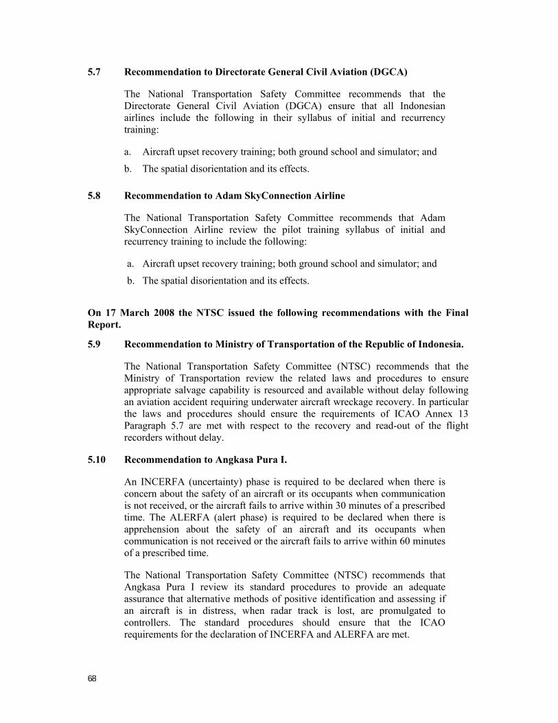
68
5.7 Recommendation to Directorate General Civil Aviation (DGCA)
The National Transportation Safety Committee recommends that the Directorate General Civil Aviation (DGCA) ensure that all Indonesian airlines include the following in their syllabus of initial and recurrency training:
a. Aircraft upset recovery training; both ground school and simulator; and
b. The spatial disorientation and its effects.
5.8 Recommendation to Adam SkyConnection Airline
The National Transportation Safety Committee recommends that Adam SkyConnection Airline review the pilot training syllabus of initial and recurrency training to include the following:
a. Aircraft upset recovery training; both ground school and simulator; and
b. The spatial disorientation and its effects.
On 17 March 2008 the NTSC issued the following recommendations with the Final Report.
5.9 Recommendation to Ministry of Transportation of the Republic of Indonesia.
The National Transportation Safety Committee (NTSC) recommends that the Ministry of Transportation review the related laws and procedures to ensure appropriate salvage capability is resourced and available without delay following an aviation accident requiring underwater aircraft wreckage recovery. In particular the laws and procedures should ensure the requirements of ICAO Annex 13 Paragraph 5.7 are met with respect to the recovery and read-out of the flight recorders without delay.
5.10 Recommendation to Angkasa Pura I.
An INCERFA (uncertainty) phase is required to be declared when there is concern about the safety of an aircraft or its occupants when communication is not received, or the aircraft fails to arrive within 30 minutes of a prescribed time. The ALERFA (alert phase) is required to be declared when there is apprehension about the safety of an aircraft and its occupants when communication is not received or the aircraft fails to arrive within 60 minutes of a prescribed time.
The National Transportation Safety Committee (NTSC) recommends that Angkasa Pura I review its standard procedures to provide an adequate assurance that alternative methods of positive identification and assessing if an aircraft is in distress, when radar track is lost, are promulgated to controllers. The standard procedures should ensure that the ICAO requirements for the declaration of INCERFA and ALERFA are met.

69
5.11 Recommendation to AdamAir.
The National Transportation Safety Committee (NTSC) recommends that AdamAir should review the effectiveness of its training for cockpit crews, specifically related to crew resource management, safety critical systems, and the appropriate use of standard operating procedures, including the Quick Reference Handbook.

70
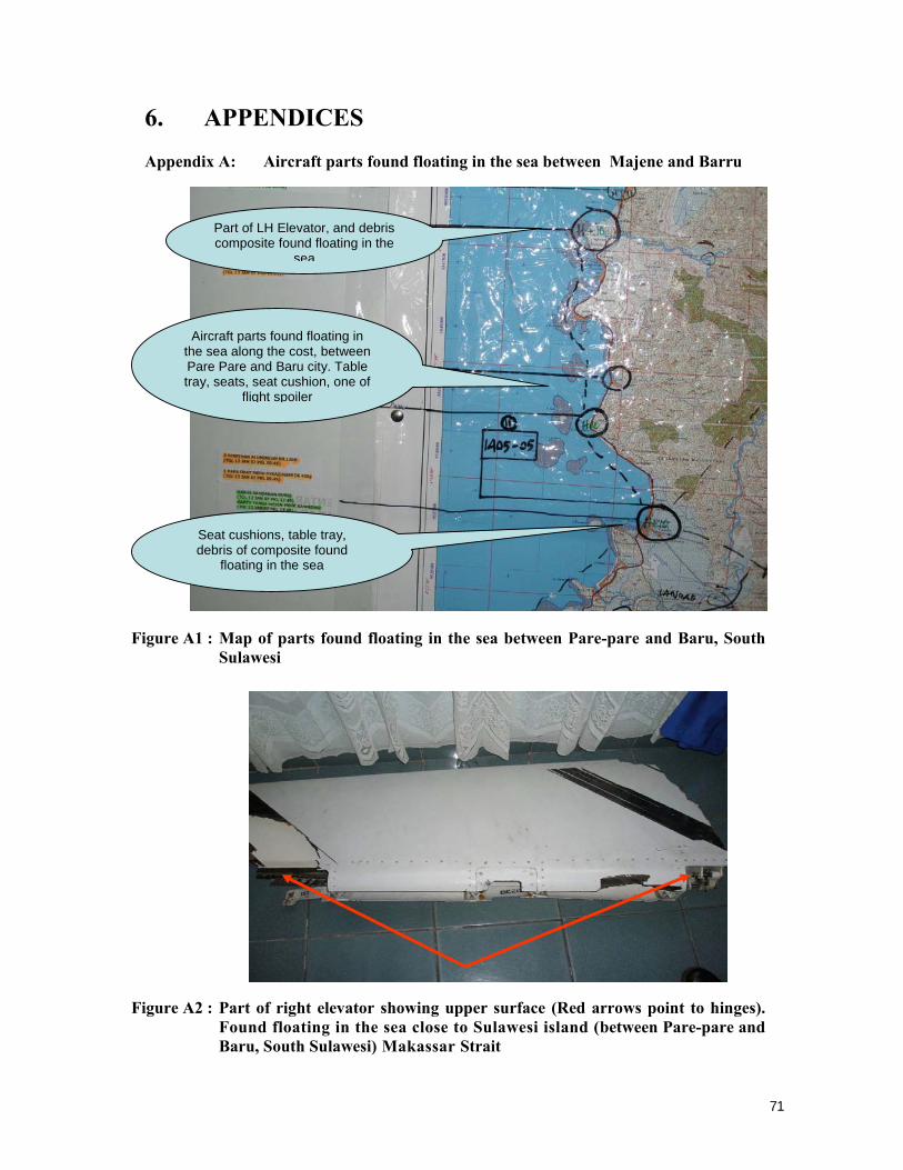
71
6. APPENDICES Appendix A: Aircraft parts found floating in the sea between Majene and Barru
Figure A1 : Map of parts found floating in the sea between Pare-pare and Baru, South Sulawesi
Figure A2 : Part of right elevator showing upper surface (Red arrows point to hinges).
Found floating in the sea close to Sulawesi island (between Pare-pare and Baru, South Sulawesi) Makassar Strait
Aircraft parts found floating in the sea along the cost, between Pare Pare and Baru city. Table tray, seats, seat cushion, one of
flight spoiler
Part of LH Elevator, and debris composite found floating in the
sea
Seat cushions, table tray, debris of composite found
floating in the sea
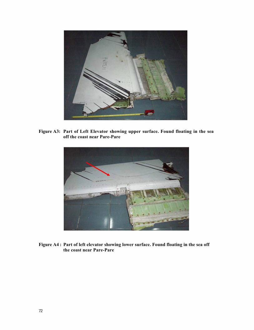
72
Figure A3: Part of Left Elevator showing upper surface. Found floating in the sea off the coast near Pare-Pare
Figure A4 : Part of left elevator showing lower surface. Found floating in the sea off the coast near Pare-Pare
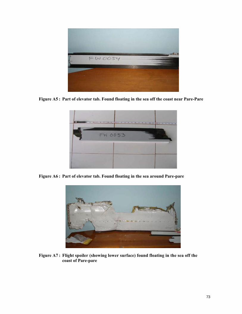
73
Figure A5 : Part of elevator tab. Found floating in the sea off the coast near Pare-Pare
Figure A6 : Part of elevator tab. Found floating in the sea around Pare-pare
Figure A7 : Flight spoiler (showing lower surface) found floating in the sea off the coast of Pare-pare
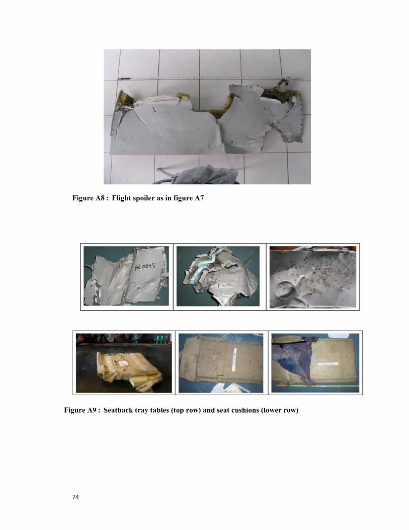
74
Figure A8 : Flight spoiler as in figure A7
Figure B - 1 Seat structure Figure A9 : Seatback tray tables (top row) and seat cushions (lower row)
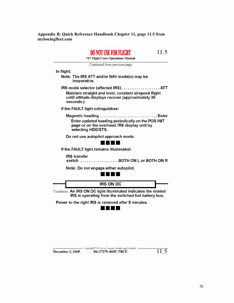
75
Appendix B: Quick Reference Handbook Chapter 11, page 11.5 from myboeingfleet.com
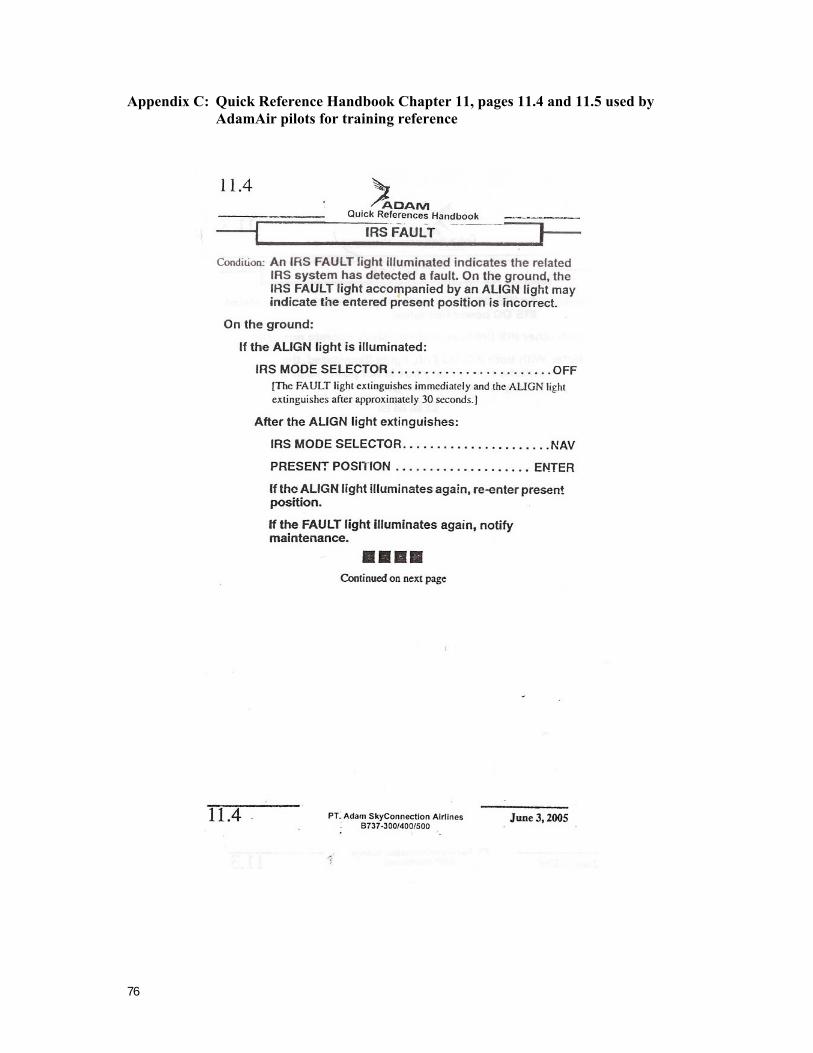
76
Appendix C: Quick Reference Handbook Chapter 11, pages 11.4 and 11.5 used by AdamAir pilots for training reference
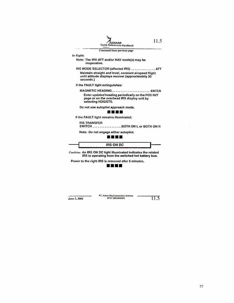
77
78
Appendix D: Human Factors Human Factors
Flightcrews have become more reliant upon the functioning of sophisticated avionics systems, and their associated automation to operate transport category aircraft. Basic control of the aircraft and supervision of the flight’s progress by instrument indications diminish as other tasks in the cockpit attract attention. Research has indicated that crews’ depend on the reliability and capability of the autopilot to a far greater degree than was originally anticipated. However, the autopilot may not function as anticipated when other system anomalies occur. This will depend on the inter-relationships between the various systems (e.g. FMC, IRS, mode settings) and what information they are using. There is extensive research on crews’ over reliance on such equipment. This has been a well known concern in airline operations for several decades, with a number of publications on the subject.25
To help overcome these problems, companies normally provide crews with specific procedures and simulator training to ensure that one pilot will monitor the progress of the aircraft at all times, under all circumstances. This was an issue in the PK-KKW accident, because the PIC did not clearly articulate an appropriate distribution of tasks to be performed by the crew when there appeared to be a significant IRS problem.
Even though the right, (number-1 2) IRS was switched to ATTitude the PIC’s flight instruments should not have been affected and the Standby ADI was available, and therefore available to ensure the safe operation of the aircraft.
Situational awareness
Situational Awareness (SA) is a term that has been very difficult for researchers and practitioners to define. Nevertheless, it is a term that is often used to explain the causes of system failures. Typically, these failures involve a breakdown in the process of acquiring and processing task-related information such that valuable cues are either overlooked (lapse) or misinterpreted (mistake). To that end, SA relates primarily to the initial stages of information processing where information is acquired and examined, and on which subsequent decisions are made.
Situational awareness refers to the pilot’s “perception of elements in the environment within a volume of time and space, the comprehension of their meaning, and the projection of their status in the near future” (Endsley, 1995, p. 36). According to Endsley, SA can be considered as knowledge of what is happening An
25 Bureau of Air Safety Investigation (now Australian Transport Safety Bureau), (1998). Advanced Technology
Aircraft Safety Survey Report, Canberra, Australia. ISBN: 0 642 27456 8. http://www.atsb.gov.au/publications/1998/sir199806_001.aspx
79
now (Level 1 SA), knowledge of what has happened previously (Level 2 SA), and knowledge of what is expected to occur in the future (Level 3 SA).
example of the impact of system design on SA can be drawn from the PK-KKW accident. The autopilot disengage aural cue used on board the aircraft was not salient enough to capture the flight crew’s attention during their IRS trouble-shooting. The pilots had made an erroneous assumption concerning the state of the aircraft, and did not perceive that the aircraft was no longer under the control of the autopilot. This is colloquially referred to as ‘the out of the loop’ syndrome.
Level 1 SA
The ‘out of the loop’ syndrome or a breakdown in Level 1 SA is said to occur when an automated system performs functions that are not anticipated by the operator. This tends to be the most common type of error that occurs as a result of interactions with advanced technology. Part of the difficulty appears to lie in both the accuracy and the reliability of such systems, to the extent that operators may become complacent regarding the potential system failures that may occur.
From an information processing perspective, the likelihood that a system will perform functions that are unanticipated by the operator is related to both the inherent behaviour of the automated system and the factors that impact upon the operator. Where a system is relatively unreliable, operators tend to maintain a relatively high level of vigilance, thereby decreasing the reaction time in response to an unexpected change in the system state. However, where a system is relatively reliable, operators may develop a level of trust in the system, the consequence of which may be an increase in the reaction time in response to an unexpected change in the system state.
Irrespective of issues such as design and training, the notion of advanced technology itself has implications for SA, especially in terms of failure detection and diagnosis. For example, evidence arising from research suggests that a lack of direct involvement in the performance of a task increases the time required to establish control of a system in the event of failure. Therefore, it might be asserted that the difficulty associated with advanced technology appears to arise due to the lack of cognitive involvement in the performance of a task. In the absence of such involvement, the cues arising from changes that occur within the operational environment are no longer evident, except through secondary sources such as instrumentation.
Level 2 SA
Rather than simply being aware of events that are occurring, SA also involves the interpretation and comprehension of the information arising from the environment, to the extent that some sort of meaning is derived in terms of the nature of the system (Level 2 SA). The skills necessary to derive an accurate interpretation are dependent upon a number of features including the previous experience of the operator and the nature of the representation of the domain in long-term memory. It is only by understanding the interaction between the various features that constitute the environment that a person is able to integrate relatively disparate pieces of information to form a coherent understanding of the current state of the system.
80
Ultimately, the accurate interpretation of the information arising from the operational environment is dependent upon the development and maintenance of a mental model. A mental model is a representation in the mind, of the structure and operation of a system. Mental models are developed largely through experience and active interaction with the environment. They involve the interpretation of the perceived actions of a device and the mental representation of its structure.
An inaccurate representation of the system may lead to difficulties in operating performance, particularly under conditions of high workload and/or stress. Important information that is pertinent to a problem may be overlooked or disregarded as unimportant if an operator is unable to integrate this information into a mental model of operation of the system.
One of the most important prerequisites for effective and efficient SA in a group environment involves the development and maintenance of a consistent mental model within the group. This is particularly significant during non-normal situations, as it enables the group as a team to increase the probability that subtle changes in the system state will be identified and processed.
Level 3 SA
In establishing an accurate and reliable mental model, pilots also develop the capability to anticipate the outcomes of the various actions. The capability to anticipate the impact of future events on human performance enables strategies to be devised that will minimize the potential impact of system failures. In the terms of the ‘Reason’ model, anticipation represents an opportunity to develop and implement a system defence to mitigate against a system failure.
Developing the skills necessary to anticipate the consequences of events is particularly difficult for less experienced people, and it is often developed ad hoc within the operational environment. However, the capacity to anticipate events is extremely important in complex dynamic systems, where the effectiveness of interventions is likely to diminish the longer that intervention is delayed.
Spatial disorientation
Spatial disorientation26 27 is a term used to describe a variety of incidents occurring in flight where the pilot fails to sense correctly the position, motion or attitude of his aircraft or of himself within the fixed coordinate system provided by the surface of the Earth and the gravitational vertical. In addition, errors in perception by the pilot of his position, motion or attitude with respect to his aircraft, or of his own aircraft relative to other aircraft, may also be embraced within a broader definition of spatial disorientation in flight.
26 Benson, A. (1988). Spatial disorientation – general aspects. In J. Ernsting & P. King (Eds.), Aviation
medicine (pp. 277-296). London: Butterworths & Co.Ltd. 27 Fred H. Previc and William R. Ercoline (2004). Spatial Disorientation in Aviation, American Institute of
Aeronautics and Astronautics, Reston, Virginia.
81
If the disorientation phenomenon is not recognised immediately, it may lead to loss of control of the aircraft or controlled flight into terrain with disastrous consequences. Prevention of SD is thus an important step in enhancing flight safety.28
Illusions
The somatogyral illusion29
The somatogyral illusion is also known as the graveyard spin or spiral. It is again a function of how the vestibular system works. During the entry into a spiral turn or a spin (deliberately or inadvertently), the vestibular system (in particular the semi-circular canals) will register the initial angular acceleration. This of course assumes that the entry into the turn is above the threshold for activation of the semi-circular canals.
Once the spiral turn or spin is stabilized, the angular acceleration will tend towards zero, with a constant velocity turn (ie no acceleration). In this situation the semicircular canals will not be stimulated, as they only register a change in angular velocity. The canals will effectively then signal that there is no turn happening. The visual system, however, being the dominant orientation mechanism, will over-ride the vestibular system signals and confirm the ongoing turn, due to the outside visual world rotating as the turn continues.
However, if there are poor visual cues, the pilot may experience a sensation that they are no longer turning. When the spiral turn or spin is halted, and a return to straight and level flight affected, the semi-circular canals may register the change in angular velocity associated with the cessation of turning. This can then create an illusion within the pilot that they are now turning in the opposite direction to the original turn. This strong sense of false rotation may lead, in the absence of good visual cues, to a re-entry into the original turn or spin. This may cancel out the false sense of rotation, with the pilot now believing that they are straight and level, but in fact they have re-entered the original turn or spin, and be losing altitude as a result. Unless this dangerous situation is recognized and appropriate recovery steps taken, impact with the ground will inevitably result.
The link between the visual and vestibular systems (as mentioned previously) is very obvious during the somatogyral illusion. Upon recovery from the spin or prolonged spiral turn, the semi-circular canals signal the false sense of rotation in the opposite direction. This vestibular input then can result in a series of involuntary oscillatory eye movements known as nystagmus. This can then lead to the oculogyral illusion, where the visual field appears to move, and in so doing tends to reinforce the false sense of rotation. In effect, the pilot then gets apparently confirmatory visual evidence of rotation, which can lead the pilot to re-enter the original turn. This combined effect makes this illusion extremely dangerous.
28 Newman, D, (2007). An overview of spatial disorientation as a factor in aviation accidents and incidents.
Canberra, ACT: Australian Transport Safety Bureau. ISBN 978-1-921165-52-8 29 Benson, A. (1988). Spatial disorientation – common illusions. In J. Ernsting & P. King (Eds.), Aviation
medicine (pp. 297-317). London: Butterworths & Co.Ltd.
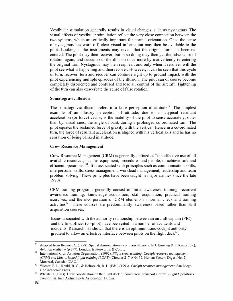
82
Vestibular stimulation generally results in visual changes, such as nystagmus. The visual effects of vestibular stimulation reflect the very close connection between the two systems, which are critically important for normal orientation. Once the sense of nystagmus has worn off, clear visual information may then be available to the pilot. Looking at the instruments may reveal that the original turn has been re-entered. The pilot may then recover, but in so doing may then get the false sense of rotation again, and succumb to the illusion once more by inadvertently re-entering the original turn. Nystagmus may then reappear, and only when it resolves will the pilot see what is happening and then recover. However, it can be seen that this cycle of turn, recover, turn and recover can continue right up to ground impact, with the pilot experiencing multiple episodes of the illusion. The pilot can of course become completely disoriented and confused and lose all control of the aircraft. Tightening of the turn can also exacerbate the sense of false rotation.
Somatogravic illusion
The somatogravic illusion refers to a false perception of attitude.30 The simplest example of an illusory perception of attitude, due to an atypical resultant acceleration (or force) vector, is the inability of the pilot to sense accurately, other than by visual cues, the angle of bank during a prolonged co-ordinated turn. The pilot equates the sustained force of gravity with the vertical. Hence in a co-ordinated turn, the force of resultant acceleration is aligned with his vertical axis and he has no sensation of being banked in attitude.
Crew Resource Management
Crew Resource Management (CRM) is generally defined as “the effective use of all available resources, such as equipment, procedures and people, to achieve safe and efficient operations”31. It is associated with principles such as communication skills, interpersonal skills, stress management, workload management, leadership and team problem solving. These principles have been taught in major airlines since the late 1970s.
CRM training programs generally consist of initial awareness training, recurrent awareness training, knowledge acquisition, skill acquisition, practical training exercises, and the incorporation of CRM elements in normal check and training activities32. These courses are predominantly awareness based rather than skill acquisition courses.
Issues associated with the authority relationship between an aircraft captain (PIC) and the first officer (co-pilot) have been cited in a number of accidents and incidents. Research has shown that there is an optimum trans-cockpit authority gradient to allow an effective interface between pilots on the flight deck33.
30 Adapted from Benson, A. (1988). Spatial disorientation – common illusions. In J. Ernsting & P. King (Eds.),
Aviation medicine (p 297). London: Butterworths & Co.Ltd. 31 International Civil Aviation Organization. (1992). Flight crew training: Cockpit resource management
(CRM) and Line-oriented flight training (LOFT) (Circular 217-AN/132, Human Factors Digest No. 2). Montreal, Canada: ICAO.
32 Wiener, E. L., Kanki, B. G., & Helmreich, R. L. (Eds.) (1993). Cockpit resource management. San Diego, CA: Academic Press.
33 Wheale, J. (1983). Crew coordination on the flight deck of commercial transport aircraft. Flight Operations Symposium. Irish Airline Pilots Association. Dublin.
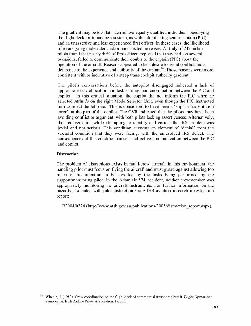
83
The gradient may be too flat, such as two equally qualified individuals occupying the flight deck, or it may be too steep, as with a dominating senior captain (PIC) and an unassertive and less experienced first officer. In these cases, the likelihood of errors going undetected and/or uncorrected increases. A study of 249 airline pilots found that nearly 40% of first officers reported that they had, on several occasions, failed to communicate their doubts to the captain (PIC) about the operation of the aircraft. Reasons appeared to be a desire to avoid conflict and a deference to the experience and authority of the captain34. Those reasons were more consistent with or indicative of a steep trans-cockpit authority gradient.
The pilot’s conversations before the autopilot disengaged indicated a lack of appropriate task allocation and task sharing, and coordination between the PIC and copilot. In this critical situation, the copilot did not inform the PIC when he selected Attitude on the right Mode Selector Unit, even though the PIC instructed him to select the left one. This is considered to have been a ‘slip’ or ‘substitution error’ on the part of the copilot. The CVR indicated that the pilots may have been avoiding conflict or argument, with both pilots lacking assertiveness. Alternatively, their conversation while attempting to identify and correct the IRS problem was jovial and not serious. This condition suggests an element of ‘denial’ from the stressful condition that they were facing, with the unresolved IRS defect. The consequences of this condition caused ineffective communication between the PIC and copilot.
Distraction
The problem of distractions exists in multi-crew aircraft. In this environment, the handling pilot must focus on flying the aircraft and must guard against allowing too much of his attention to be diverted by the tasks being performed by the support/monitoring pilot. In the AdamAir 574 accident, neither crewmember was appropriately monitoring the aircraft instruments. For further information on the hazards associated with pilot distraction see ATSB aviation research investigation report:
B2004/0324 (http://www.atsb.gov.au/publications/2005/distraction_report.aspx).
34 Wheale, J. (1983). Crew coordination on the flight deck of commercial transport aircraft. Flight Operations
Symposium. Irish Airline Pilots Association. Dublin.
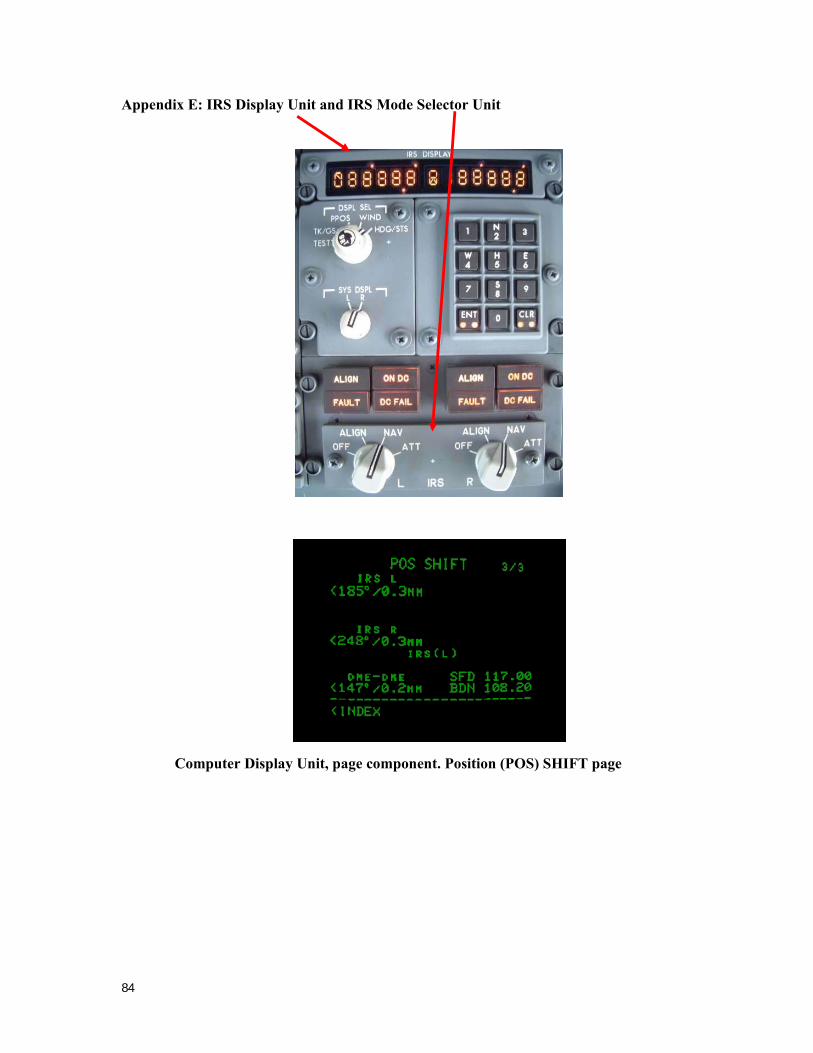
84
Appendix E: IRS Display Unit and IRS Mode Selector Unit
Computer Display Unit, page component. Position (POS) SHIFT page