Embed Size (px)
Citation preview

KNKT/97.29/04.06.016
NNaattiioonnaall TTrraannssppoorrttaattiioonn SSaaffeettyy CCoommmmiitttteeee Final Report Garuda Indonesia Flight GA 152
Airbus A300-B4
PK-GAI
Buahnabar, Sumatera Utara, Indonesia
26 SEPTEMBER 1997
NATIONAL TRANSPORTATION SAFETY COMMITTEE DEPARTMENT OF COMMUNICATIONS REPUBLIC OF INDONESIA 2004

When the Committee makes recommendations as a result of its
investigations or research, safety is its primary consideration.
However, the Committee fully recognizes that the implementation of
recommendations arising from its investigations will in some cases
incur a cost to the industry.
Readers should note that the information in NTSC reports is provided
to promote aviation safety: in no case is it intended to imply blame or
liability.
This report has been prepared based upon the investigation carried out by the National Transportation Safety Committee in accordance with Annex 13 to the Convention on
International Civil Aviation, UU No.15/1992 and PP No. 3/2001. This report was produced by the National Transportation Safety Committee (NTSC), Gd. Karsa Lt.2 Departemen Perhubungan, Jalan Medan Merdeka Barat 8 JKT 10110 Indonesia. Readers are advised that the Committee investigates for the sole purpose of enhancing aviation safety. Consequently, Committee reports are confined to matters of safety significance and maybe misleading if used for any other purpose. As NTSC believes that safety information is of greatest value if it is passed on for the use of others, readers are encouraged to copy or reprint for further distribution, acknowledging NTSC as the source.

this page intentionally left blank

i
TABLE OF CONTENTS
TABLE OF CONTENTS i
LIST OF FIGURES iv
LIST OF APPENDICES v
GLOSSARY vi
INTRODUCTION 1
1 FACTUAL INFORMATION 3
1.1 History of Flight 3
1.2 Injuries to Persons 4
1.3 Damage to Aircraft 4
1.4 Other Damage 5
1.5 Personnel Information 5
1.5.1 Flight crew 5 1.5.1.1 Pilot-In-Command (PIC) 6 1.5.1.2 Co-pilot 7
1.5.2 ATC Personnel 7 1.5.2.1 ATC Radar Approach Controller 7
1.6 Aircraft Information 8
1.6.1 Aircraft Data 8 1.6.2 Engine Data 8 1.6.3 Maintenance Data 8 1.6.4 Ground Proximity Warning System 9 1.6.5 Weight and Balance 10
1.7 Meteorological Information 10
1.8 Aids to Navigation 11
1.8.1 Instrument Landing System (ILS) 11 1.8.2 Radar system 11
1.9 Communications 13
1.10 Aerodrome Information 13
1.11 Flight Recorders 14
1.11.1 Recovery of Flight Recorders 14 1.11.2 Digital Flight Data Recorder 14

ii
1.11.3 Cockpit Voice Recorder 15 1.11.4 FDR-CVR Data Integration 15
1.12 Wreckage and impact information 16
1.12.1 Accident site description 16 1.12.2 Airframe 18 1.12.3 Landing gear 19 1.12.4 Engines 19 1.12.5 APU 19 1.12.6 Instruments and Flight Controls 19
1.12.6.1 Flight deck central pedestal 19 1.12.6.2 Instruments 20 1.12.6.3 Engine instruments 20 1.12.6.4 Altimeters and air speed 20 1.12.6.5 Fuel system 21 1.12.6.6 Flight control system 21
1.13 Medical and pathological information 21
1.13.1 Evacuation and identification of remains 21 1.13.2 Injuries to victims 22
1.14 Fire 22
1.15 Survival Aspect 22
1.16 Test and research 22
1.16.1 Flight Simulations 22 1.16.2 Ground Proximity Warning System (GPWS) Simulation Test 23
1.17 Organization and management information 24
1.17.1 PT. Garuda Indonesia 24 1.17.2 PT. Angkasa Pura II 25
1.18 Additional information 25
1.18.1 Weather minimum policy from the regulatory body 25 1.18.2 Flight Dispatching 26 1.18.3 Required and available ATC personnel 27 1.18.4 Pilot Conversion Training Program from A300-600 to A300-B4 27 1.18.5 Automatic Flight System 28
1.18.5.1 Longitudinal Modes 28 1.18.5.2 Lateral Modes 28
1.18.6 Ground Proximity Warning System (GPWS) escape maneuver 29
2 ANALYSIS 30
2.1 General 30
2.2 Polonia Airport Operations 30
2.2.1 Reciprocal runway operation 30 2.2.2 Polonia Airport operation during reduced visibility 30
2.3 Dispatching Practices 31

iii
2.4 Radar Vectoring 31
2.4.1 Radar vectoring acceptance in IMC below Minimum Safe Altitude 31 2.4.2 Radar vectoring practices 32
2.5 Situational Awareness 34
2.5.1 Pilot-Flying’s Expectations 34 2.5.2 Distraction from flight path monitoring duties 35 2.5.3 Altitude Awareness 35
2.6 Crew Resource Management 36
2.6.1 Inter-crew communication problem 36 2.6.2 Adherence to the Standard Operating Procedures 37
2.7 Medan Approach Controller 37
2.7.1 Incorrect call-sign 37 2.7.2 Non-standard phraseology 38 2.7.3 Controller’s workload 39
2.8 Flight Automation 39
2.8.1 Longitudinal Modes 39 2.8.2 Lateral Modes 40
2.9 GPWS 41
2.9.1 Aural and Visual Warning 41 2.9.2 Mode 2A Warning Envelope 41 2.9.3 GPWS Functional Check 42
2.10 A300-600 to A300-B4 Pilot Conversion Training Approval 43
3 CONCLUSIONS 44
3.1 Findings 44
3.2 Probable Cause 45
4 RECOMMENDATIONS 46
CHARTS AND PHOTOGRAPHS 47
REFERENCES 69
APPENDICES 70

iv
LIST OF FIGURES
Figure 1. Localizer footprint chart 47
Figure 2. Minimum Vectoring Altitude Chart 48
Figure 3. Medan-Polonia Airport Chart (Jeppessen) 49
Figure 4. Medan ILS Approach Chart (Jeppessen) 50
Figure 5. A300-B4 Cutaway Drawing 51
Figure 6. A300-B4 Cockpit Instrumentation 52
Figure 7. A300-600 Cockpit Instrumentation 53
Figure 8. A300B4 Horizontal Situation Indicator 54
Figure 9. A300-600 Navigation Display 54
Figure 10. Initial impact tree, looking 060o M 55
Figure 11. Main crash site, looking 235o M 56
Figure 12. Main crash site- aft fuselage and empennage 56
Figure 13. Crash site (1), an area of abandoned rice paddy terraces 57
Figure 14. Crash site (2) 58
Figure 15. Crash site (3) 59
Figure 16. RH wing tip fairing and LE structure 60
Figure 17. LH Low-speed Aileron 61
Figure 18. RH low-speed aileron 61
Figure 19. LH P&W JT9D engine, nose down 62
Figure 20. RH P&W JT9D engine, buried 62
Figure 21. Part of central pedestal 63
Figure 22. Flap screwjack and flap carriage 63
Figure 23. Instrument – RMI 64
Figure 24. Instrument - Servo Altimeter 64
Figure 25. Seat numbers of unidentified victims according to passenger list 65
Figure 26. Plot of altitude vs time 66
Figure 27. Occasions where GPWS terrain closure rate should generate warning 66
Figure 28. GA 152 last FDR track on visual chart 67
Figure 29. GA 152 Flight path and communications 68
v
LIST OF APPENDICES Appendix A. Wreckage Distribution
Appendix B. Transcript of the CVR recording
Appendix C. FDR Plot
Appendix D. NOTAM Class II no. 1-02/83
Appendix E. Approach Radar Vectoring Guidance for Visual and ILS Interception
Appendix F. Automatic Flight System – Relevant Longitudinal Modes
Appendix G. Automatic Flight System – Relevant Lateral Modes
Appendix H. GPWS Escape Maneuver Procedure
vi
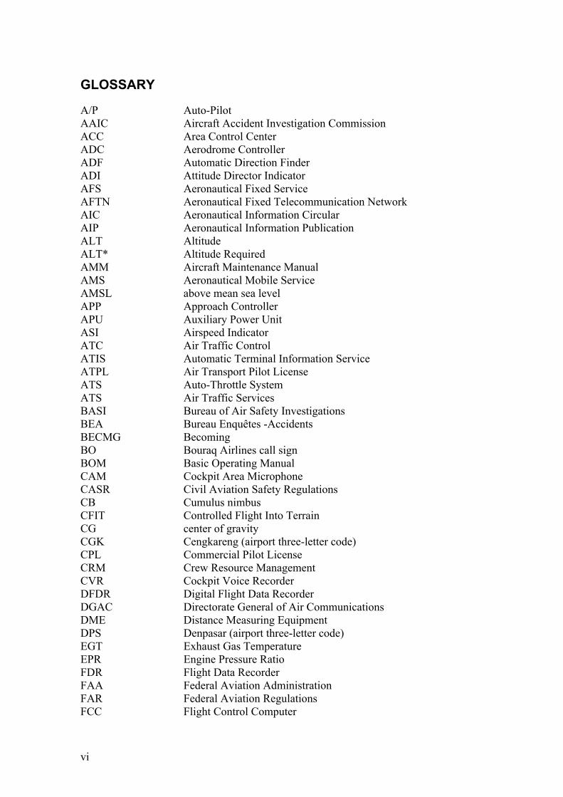
GLOSSARY
A/P Auto-Pilot AAIC Aircraft Accident Investigation Commission ACC Area Control Center ADC Aerodrome Controller ADF Automatic Direction Finder ADI Attitude Director Indicator AFS Aeronautical Fixed Service AFTN Aeronautical Fixed Telecommunication Network AIC Aeronautical Information Circular AIP Aeronautical Information Publication ALT Altitude ALT* Altitude Required AMM Aircraft Maintenance Manual AMS Aeronautical Mobile Service AMSL above mean sea level APP Approach Controller APU Auxiliary Power Unit ASI Airspeed Indicator ATC Air Traffic Control ATIS Automatic Terminal Information Service ATPL Air Transport Pilot License ATS Auto-Throttle System ATS Air Traffic Services BASI Bureau of Air Safety Investigations BEA Bureau Enquêtes -Accidents BECMG Becoming BO Bouraq Airlines call sign BOM Basic Operating Manual CAM Cockpit Area Microphone CASR Civil Aviation Safety Regulations CB Cumulus nimbus CFIT Controlled Flight Into Terrain CG center of gravity CGK Cengkareng (airport three-letter code) CPL Commercial Pilot License CRM Crew Resource Management CVR Cockpit Voice Recorder DFDR Digital Flight Data Recorder DGAC Directorate General of Air Communications DME Distance Measuring Equipment DPS Denpasar (airport three-letter code) EGT Exhaust Gas Temperature EPR Engine Pressure Ratio FDR Flight Data Recorder FAA Federal Aviation Administration FAR Federal Aviation Regulations FCC Flight Control Computer

vii
FCOM Flight Crew Operation Manual FCU Fuel Control Unit FCU Flight Control Unit FDR Flight Data Recorder FF Fuel flow FIR Flight Information Region FL Flight level FMA Flight Mode Annunciator ft feet FU Smoke FU Fuel Used GA Garuda Indonesia call sign GPS Global Positioning System GPWC Ground Proximity Warning Computer GPWS Ground Proximity Warning System HDG Heading HSEL Heading Select HZ Hazy ICAO International Civil Aviation Organization ILS Instrument Landing System IMC Instrument Meteorological Conditions Khz Kilohertz KT Knots LH Left Hand LVL/CHG Level Change MDC Manado (airport three-letter code) MDN Medan VOR MES Medan (airport three-letter code) MHz Megahertz (frequency) MORA Minimum Off-Route Altitude MPD Maintenance Planning Document MRB Maintenance Review Board MSA Minimum Sector Altitude MSAWS Minimum Safe Altitude Warning System MSI Maintenance Specification Item MTOW Maximum Take-Off Weight MVA Minimum Vectoring Altitude N1 Engine Fan Speed N2 Engine Compressor Speed NDB Non-Directional Beacon NM nautical miles NOTAM Notice to Airmen NTSC National Transportation Safety Committee PF Pilot Flying PIC Pilot in Command PLP Pendidikan dan Latihan Penerbangan (Aviation Education and
Training Center) P/N Part Number PNF Pilot Non Flying PSR Primary Surveillance Radar

viii
QAM Meteorological Station Report for Landing QNH Pressure setting to indicate elevation above Mean Sea Level RH right hand S/N Serial Number SAR Search and Rescue SCT Scattered SOP Standard Operating Procedures SSA Sector Safe Altitude SSR Secondary Surveillance Radar TAFOR Terminal weather forecast TCC Thrust Control Computer TEMPO Temporary TMA Terminal Area Control TNI Tentara Nasional Indonesia (National Armed Forces) TSO Technical Standard Order ULB Underwater Locator Beacon UTC Universal Time Coordinated
All times indicated in this report are based on FDR UTC Time.Local time is UTC + 7 hours.
V/S Vertical Speed VHF Very High Frequency VMC Visual Meteorological Conditions VOR VHF Omnidirectional Range VRB Variable

1
INTRODUCTION
Synopsis On 26 September 1997, the Garuda Flight GA 152 departed from Soekarno-Hatta International Airport, Jakarta at 04:41 UTC with an estimated time of arrival at 06:41 UTC. The weather en-route was reported clear with scattered clouds. The visibility at Medan Polonia International Airport was less than 500 meters due to the smoke of forest fires in Riau, South Sumatera and Kalimantan. Approaching Polonia International Airport, Medan, the aircraft followed the instructions of Medan Approach, based on local radar vectoring guidance. Just seconds before impact the flight crew became aware that they were below the assigned altitude of 2000 ft. In spite of the immediate corrective action taken by the crew, the aircraft struck a treetop on a ridge at about 1550 ft above sea level, separating about nine feet of the right-hand wing tip. It rendered the aircraft uncontrollable, spilling fuel along its final track until it hit the ground in an abandoned rice field at the bottom of a ravine approximately 600 meters from the first tree impact. The crash location was at Latitude N 03°20’28.2”, Longitude E 98°34’26.6”, approximately 14.6 NM south west (205 degrees magnetic) of Polonia Airport. The aircraft was totally destroyed and the accident was non-survivable and all persons on board perished, including 222 passengers and 12 crewmembers. The flight data and cockpit voice recorders indicated that the aircraft was in controlled flight until it struck trees at the top of a ridge. Consequently, this accident may be categorized as a Controlled Flight Into Terrain (CFIT). CFIT accident is characterized by a loss of three-dimensional spatial awareness. It was found that a number of factors contributed to the flight crew’s loss of spatial awareness, vertical as well as horizontal. Investigation Process The Aircraft Accident Investigation Commission (now the National Transportation Safety Committee) was notified within hours after the occurrence happened and a team of 7 investigators including the IIC were assigned. The AAIC and the Bureau Enquêtes-Accidents of France, participating as accredited representative, were assisted by the experts and the facilities provided by the Australian Bureau of Air Safety Investigation (now the Australian Transport Safety Bureau), the Air Accident Investigation Branch of United Kingdom, and Airbus. The Civil Aviation Authority of Singapore also participated as observer. The international team of investigators began their investigation two days after the day of the occurrence and after the search for, and the removal of the victims remains were concluded. The search for the Flight Data and Cockpit Voice Recorders took 22 days until the recovery of the recorders entangled in the roots of a tree at the perimeter of the accident site. The wreckage parts and its relative locations were documented.
2
Information on the flight, the aircraft, and the crew as well as other relevant and supporting information were obtained from Garuda Indonesia, Medan Polonia Airport, Airbus, Honeywell, the Directorate General of Air Communications, and other institutions. Eyewitnesses on the ground, and a number of directly and indirectly involved personnel were interviewed. The analytical efforts started earnestly after the successful read-outs of the recorders at the BASI facilities in Canberra. The investigation process was hampered by the SilkAir MI185 aircraft fatal accident in Palembang two months after the occurrence, and the limited number of the AAIC investigators and research personnel. However, several intermediate and urgent safety recommendations were made to the Indonesian Minister of Communications immediately after the safety deficiencies were identified. This final report contains the factual information, analysis, conclusions and recommendations to the appropriate authorities/organizations as the result of the investigation.

3
1 FACTUAL INFORMATION
1.1 History of Flight
On 26 September 1997 the Garuda Indonesia Flight GA 152, PK-GAI Airbus A300-B4 departed from the Jakarta Soekarno-Hatta International Airport at 04:41 UTC. The aircraft was on a regular scheduled passengers flight to Polonia International Airport of Medan, North Sumatera with estimated time of arrival 06:41 UTC. Flight GA 152 was flying under Instrument Flight Rules during daylight. Before the flight, the flight crew reported to Garuda Indonesia Flight Operations office to receive flight briefings, including Notice to Airmen (NOTAM), weather conditions and forecast en-route, at destination and alternate airports, as well as the flight plan. The NOTAM stated that the MDN VOR was overdue for maintenance and advised to use the facility ‘with caution', although the Medan VOR has been calibrated with both ground and flight calibration on 14 June 1997 and valid until 14 December 1997, the use of Medan VOR was classified as “restricted due to radial course alignment at 270 degrees radial”. At the time of flight-planning, the visibility from Medan TAFOR (26 September 1997, 00.00 UTC – 24.00 UTC) was 1000 meters in smoke. The dispatcher stated that he received information through company channel that the actual visibility at Medan was 400 meters in smoke, which was below the minimum required visibility for runway 05 ILS of 800 meters. At 06:12:51 GA 152 requested a descend clearance to Medan Control. Medan Control cleared the aircraft to descend to FL 150. On passing FL 150, GA 152 was informed that the aircraft was in radar contact, at a distance of 43 nautical miles from MDN VOR/DME. The crew was then instructed to descend to 3000 ft for a landing on Runway 05 and to reduce the speed to 220 knots to allow Bouraq flight BO 683 to take-off from Runway 23 at 06:20:47. GA152 requested a speed of 250 knots below 10000 feet which was approved. At 6:27:12, Medan Approach instructed GA 152 to maintain altitude on heading to Medan VOR/DME. GA 152 confirmed this instruction at 6:27:21. At 06:27:50 Medan Approach transmitted an instruction “Merpati one five two you er .. turn left heading two four zero vectoring for intercept ILS runway zero five from the right side traffic now er.. rolling”. There was no response by any aircraft to this transmission. At 06:28:06 Medan Approach enquired “Indonesia one five two do you read”. GA 152 asked the ATC to repeat the message. At 06:28:13 Medan Approach instructed GA 152 to “Turn left heading er.. two four zero two three five now vectoring for intercept ILS runway zero five”. This instruction was acknowledged by GA 152. At 06:28:52 the PIC asked the Medan Approach whether the aircraft was clear from the mountainous area northwest from Medan. This was confirmed by Medan Approach, and GA 152 was instructed to continue turning left on heading 215°M. At 06:29:41, GA 152 was instructed to descend to 2000 ft and the crew acknowledged it. Recorded FDR information indicates the aircraft is essentially wings level, heading approx 225M° and passing through 3000 feet on descent. Then at 06:30:04 GA 152 was instructed to turn right heading 046 degrees, and to report when established on the localizer. This was acknowledged by GA 152, but misread the

4
heading “Turn right heading zero four zero Indonesia one five two check established”. Meanwhile recorded FDR information indicates the aircraft commences a roll to the left, heading reducing indicating a left turn and passing through 2600 feet on descent. At 6:30:33, while turning left, First Officer reminded the Captain to turn right. Two seconds later GA 152 queried Medan Approach whether the turn is to the left or to the right onto heading 046 degrees. At 6:30:39 Medan Approach replied “Turning right Sir”, which was acknowledged by GA 152. FDR data shows that the aircraft began to roll to wings level. At 06:30:51 Medan Approach asked whether GA 152 was making a left turn or a right turn. Recorded FDR information indicates the aircraft was wings level and rolling to the right, heading approximately 135°M and increasing, at 2035 feet pressure altitude on descent. GA 152 responded “We are turning right now”. At 06:31:05 Medan Approach instructed GA 152 to continue turning left. Recorded FDR information showed that at this point the aircraft had passed the assigned 2000 ft altitude and continued descending. GA 152 replied “Err...confirm turning left we are starting to turn right now”. During the interview, the controller stated that it was around this time that he recognized that the aircraft went below the required altitude (1800 ft and descending). Recorded FDR information indicates the aircraft reduced right roll from approx 24.3º to 10.2° and then rolled right again to approx 25°, while heading was increasing indicated a right turn was being maintained and the aircraft continued descending. At 06:31:32 the sound of tree impact is recorded. The elevation of the initial impact with the trees was at about 1550 ft above sea level. The final impact on the bottom of a ravine approximately 600 meters from the first tree impact destroyed the aircraft, and 234 people on board of the aircraft perished. There were no ground casualties.
1.2 Injuries to Persons
Injuries Crew Passengers Others Fatal 12 222 0 Serious 0 0 0 Minor/None 0 0 0 Total 12 222 0
Note: There was a total of 222 passengers on board including 2 Garuda extra crew (B747-400).
1.3 Damage to Aircraft
The initial impact against the treetops on top of a ridge occurred to the right wing. The elevation of the initial impact was at about 1550 ft above sea level, which was consistent with FDR data. The impact mark of the wing leading edge against the tree trunk was found at about 1.5 m from the wing tip. The impact caused the wingtip (± 1.5 meters from the wingtip), and 2 meters of the low speed aileron to separate from the wing. The damage to the wing apparently ruptured the right hand outer fuel tank,
5
spilling fuel as indicated by discoloration of the tree foliage along the approximate ground track of the aircraft.
The aircraft then impacted the ground at the bottom of a ravine at horizontal distance of about 500 m from the first tree on the ridge impact point, at an elevation of approximately 400 ft below the tree elevation. A large tree trunk at the bottom of the ravine was found cut down at about 3 m above the ground by the aircraft structure. The aircraft was then totally destroyed and the wreckages were strewn in an area of approximately 200 m x 75 m. The aircraft disintegrated into several major structural wreckages and components, among other pieces of the cockpit section and instrumentation, several large pieces of the fuselage, part of the vertical fin box, parts of the horizontal stabilizers, outer wings, center wing section, both the LH and RH engines, the landing gears, etc.
1.4 Other Damage
The initial impact with the tree on a ridge broke the tree trunk, approximately 1.5 to 2 meters from the top as indicated by the broken off tree trunk and branches found nearby. Foliages of the nearby trees along the approximate ground track and the immediate surroundings of the impact area were discolored by the fuel spill from the ruptured RH wing tank. An area of about 200m x 75m of abandoned rice field and forest trees was damaged by the impact and the effect of aircraft fuel spill when the aircraft impacted onto the ground.
1.5 Personnel Information
1.5.1 Flight crew
The Indonesian Directorate General of Air Communications (DGAC) properly certified the PIC and the Co-pilot. The PIC had a valid Airline Transport Pilot License, and the Co-pilot a valid Commercial Pilot License. Both were in the possession of current first class medical certificates. DGAC records showed that neither had been involved in accidents, incidents or enforcement actions. Crew training qualifications for the PIC and co-pilot were conducted at Garuda Aviation Training facility in Jakarta, consisted of ground school and simulator sessions. Crew route training was conducted in line operations within the Garuda designated route structure. A number of flights on certain routes had been conducted, and the pilots were qualified to fly the route structure.

6
1.5.1.1 Pilot-In-Command (PIC) The PIC had served as a Co-pilot on the Airbus A300B4 from 18 March 1982 until 1 June 1988. He had a valid rating as PIC on the Airbus A300-600 since 27 January 1993 until the time of the occurrence. The PIC had conducted 20 hours 35 minutes Line Training and received route qualification check on sector Jakarta-Ujung Pandang-Manado v.v. for 3 days afterward with satisfactory result as PIC on A300-B4. Before joining the A300-B4 fleet, the PIC held A300-600 rating which still required him to have qualification training before he could operate as an A300-B4 Flight Crew. The PIC underwent modified (shortened) type-qualification training for A300-B4.
Program Type Qualification Training
Total Sessions Totals hours
Result Remark
CPT(Cockpit Procedure Training) 2 08 hrs Standard Nil Simulator Training 3 1245 hrs Standard Nil Aircraft Training 1 0110 hrs Standard Nil
Flight Crew Route Training
Qualification Check as Captain A300-B4
Date Result Remark
CGK-UPG-MDC (V.V) 10 October 1996 Passed Nil
Pilot-In-Command (PIC) Co-pilot Sex Male Male Date of birth 8 October 1955 14 April 1956 Date of joining Garuda Indonesia
17 January 1978 21 June 1976
License country of issue Indonesia Indonesia License type ATPL CPL License number 2339 4815 Last Medical Check 20 August 1997 10 June 1997 Ratings Airbus A300-B4 Airbus A300-B4 Medical certificate First class – 20 August 1997 First class – Issued 10 June 1997 Aeronautical experience 11,978 hours 709 hours + training hours Experience on type 782 hours 709 hours Last 24 hours (last flight 23 Sept.1997, CGK-
DPS-CGK) 0 hours (last flight 20 Sept. 1997 CGK-MES-CGK)
Last 7 days 16.5 hours 4.35 hours Last 30 days 45.0 hours 40.0 hours Last 60 days 93.32 hours 69.35 hours Last 90 days 150.0 hours 104.0 hours Last line check 25 January 1997 10 October 1996 Last proficiency check 28 June 1997 28 June 1997 Instrument rating check 28 June 1997 15 September 1997

7
1.5.1.2 Co-pilot Before acquiring a rating for the Airbus A300-B4 the Co-pilot had served as a Flight Engineer on DC10-30 and B747-200 types from 21 June 1976 until 13 June 1996. The Co-pilot underwent standard type-qualification training for A300-B4.
Program Type Qualification Training
Total Sessions Totals hours
Result Remark
CPT(Cockpit Procedure Training) 6 17 hrs Standard Nil Simulator Training 12 1910 hrs Standard Nil Aircraft Training 2 0440 hrs Standard Nil
Flight Crew Route Training
Qualification Check as First Officer A300-B4
Date Result Remark
1. CGK-UPG-MDC (V.V) 8 May 1997 Passed Nil 2. CGK-UPG-MDC (V.V) 11 May 1997 Passed Nil
1.5.2 ATC Personnel 1.5.2.1 ATC Radar Approach Controller
The approach controller on duty at the time of the occurrence was trained according to the DGAC-approved training program. He held valid certificates for senior ATC license and radar controller ratings. To maintain his ratings current, he underwent performance checks every 6 months. His medical check was overdue (medical check should be performed annually). Basic ATC training is carried out at the Civil Aviation Training Center in Curug. There was no training facility at operational sites, in which ATC controllers can review, maintain and update their capabilities in providing air traffic services. At the time of the accident, he was assigned as Watch Supervisor. He was also assigned as Approach Controller during the morning shift on rotational basis from 03.00 UTC to 04.00 UTC and then again from 05.10 UTC to 06.40 UTC when the accident occurred. According to the duty roster, the approach controller had a 12 hours rest period prior to his duty.
Sex : Male License no. : 337-S Date of Birth : 19 June 1955 Marital Status : Married Training : 1. Junior ATC 1979 (LPPU Curug) 2. Senior ATC 1985 (PLP Curug) 3. ATC Supervisor 1995 (SAA Singapore) Rating : Radar (APP) 1985 (PLP Curug) Other training : CNS/ATM 1996 (Medan) Work Experience : 1979-1985 as ATC at Pekanbaru 1985-1997 as ATC at Medan Last performance check : 25-27 March 1997 Last Medical check : 22 May 1996
8
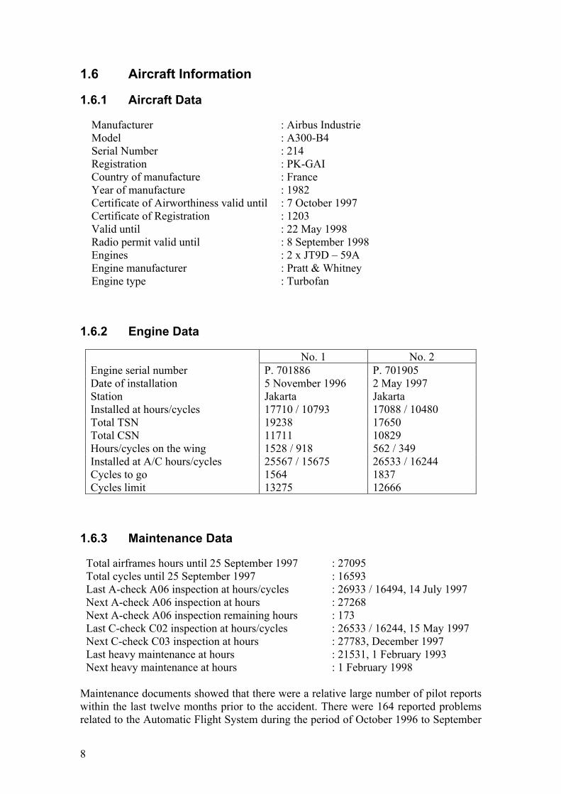
1.6 Aircraft Information
1.6.1 Aircraft Data
Manufacturer : Airbus Industrie Model : A300-B4 Serial Number : 214 Registration : PK-GAI Country of manufacture : France Year of manufacture : 1982 Certificate of Airworthiness valid until : 7 October 1997 Certificate of Registration : 1203 Valid until : 22 May 1998 Radio permit valid until : 8 September 1998 Engines : 2 x JT9D – 59A Engine manufacturer : Pratt & Whitney Engine type : Turbofan
1.6.2 Engine Data
No. 1 No. 2 Engine serial number P. 701886 P. 701905 Date of installation 5 November 1996 2 May 1997 Station Jakarta Jakarta Installed at hours/cycles 17710 / 10793 17088 / 10480 Total TSN 19238 17650 Total CSN 11711 10829 Hours/cycles on the wing 1528 / 918 562 / 349 Installed at A/C hours/cycles 25567 / 15675 26533 / 16244 Cycles to go 1564 1837 Cycles limit 13275 12666
1.6.3 Maintenance Data
Total airframes hours until 25 September 1997 : 27095 Total cycles until 25 September 1997 : 16593 Last A-check A06 inspection at hours/cycles : 26933 / 16494, 14 July 1997 Next A-check A06 inspection at hours : 27268 Next A-check A06 inspection remaining hours : 173 Last C-check C02 inspection at hours/cycles : 26533 / 16244, 15 May 1997 Next C-check C03 inspection at hours : 27783, December 1997 Last heavy maintenance at hours : 21531, 1 February 1993 Next heavy maintenance at hours : 1 February 1998
Maintenance documents showed that there were a relative large number of pilot reports within the last twelve months prior to the accident. There were 164 reported problems related to the Automatic Flight System during the period of October 1996 to September

9
1997 and 78 reported problems on the Air Conditioning System. Reported complaints on the Automatic Flight System were mostly on the Autopilot, Flight Director, ATS, pitch control, TCC, and FCC computers. There was no reported Autopilot problem within the last five days of the aircraft’s operation. According to the MSI, the maintenance procedures for GPWS system consisted of an operational check (AMM 34-48-00/P501-503, every A-check) and a functional check (AMM 34-48-00/P503-508, every C-check), which is inline with the Airbus Maintenance Planning Document (MPD). Both functional and operational tests check the audio channel. The operational check was performed on last C-Check and last A-Check. The functional check should have been performed during the C-Check. During the course of the investigation, it could not be verified whether the functional check was performed during the last C-Check. According to the aircraft manufacturer, the functional test arises from the SIL 34-035 and not from the Maintenance Review Board (MRB). This test has been implemented further to a failure of a GPWC, which inhibited all warnings, visual and audio, without detection by the BITE. This test is no more needed after application of SB 34-0121, which was not applied on PK-GAI.
1.6.4 Ground Proximity Warning System
The aircraft was equipped with Ground Proximity Warning System with following specifications: Type/Model : MKII GPWS Manufactured : AlliedSignal Commercial Avionics Systems Part Number : 965-0476-088 Serial Number : 2689 TSO : C92b The activation of the GPWS is dependent on airspeed, barometric altitude, radio altitude (i.e. height above ground level), flap position and gear position. The GPWS provides both visual and aural warning outputs during any of the following conditions:
a. Mode 1 - Excessive Sink Rate b. Mode 2 - Closure Rate;
i. Mode 2A (Flap Up) ii. Mode 2B (Flap Down)
c. Mode 3 Descend After Take Off d. Mode 4A Terrain Clearance (Gear Up) e. Mode 4B Terrain Clearance (Flap Up) f. Mode 5 Descend Below Glide Slope
Mode 2A is for flaps up or flaps partially down (as was the case for this accident).
10
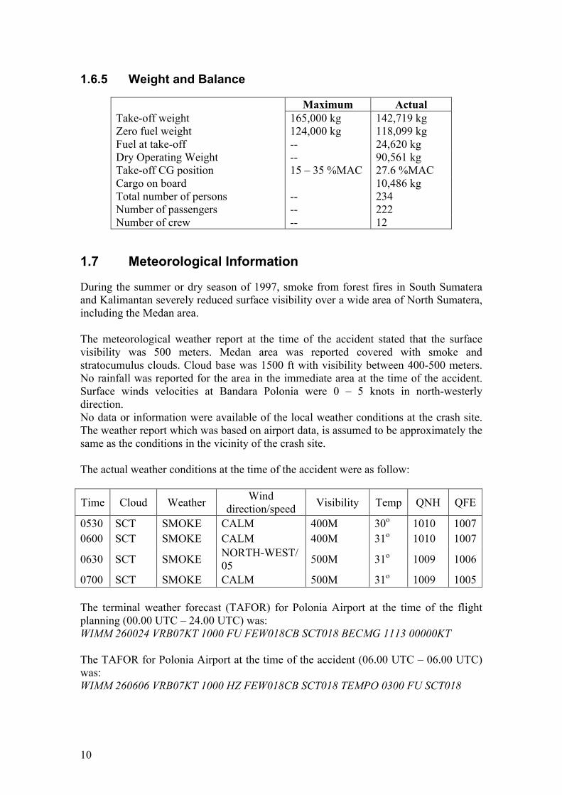
1.6.5 Weight and Balance
Maximum Actual Take-off weight 165,000 kg 142,719 kg Zero fuel weight 124,000 kg 118,099 kg Fuel at take-off -- 24,620 kg Dry Operating Weight -- 90,561 kg Take-off CG position 15 – 35 %MAC 27.6 %MAC Cargo on board 10,486 kg Total number of persons -- 234 Number of passengers -- 222 Number of crew -- 12
1.7 Meteorological Information
During the summer or dry season of 1997, smoke from forest fires in South Sumatera and Kalimantan severely reduced surface visibility over a wide area of North Sumatera, including the Medan area. The meteorological weather report at the time of the accident stated that the surface visibility was 500 meters. Medan area was reported covered with smoke and stratocumulus clouds. Cloud base was 1500 ft with visibility between 400-500 meters. No rainfall was reported for the area in the immediate area at the time of the accident. Surface winds velocities at Bandara Polonia were 0 – 5 knots in north-westerly direction. No data or information were available of the local weather conditions at the crash site. The weather report which was based on airport data, is assumed to be approximately the same as the conditions in the vicinity of the crash site. The actual weather conditions at the time of the accident were as follow:
Time Cloud Weather Wind direction/speed Visibility Temp QNH QFE
0530 SCT SMOKE CALM 400M 30o 1010 10070600 SCT SMOKE CALM 400M 31o 1010 1007
0630 SCT SMOKE NORTH-WEST/ 05 500M 31o 1009 1006
0700 SCT SMOKE CALM 500M 31o 1009 1005 The terminal weather forecast (TAFOR) for Polonia Airport at the time of the flight planning (00.00 UTC – 24.00 UTC) was: WIMM 260024 VRB07KT 1000 FU FEW018CB SCT018 BECMG 1113 00000KT The TAFOR for Polonia Airport at the time of the accident (06.00 UTC – 06.00 UTC) was: WIMM 260606 VRB07KT 1000 HZ FEW018CB SCT018 TEMPO 0300 FU SCT018

11
1.8 Aids to Navigation
The Polonia International Airport of Medan serves both international and domestic traffic. The airport has the following facilities:
Non-directional beacon (NDB) NDB freq. 375 kHz, power 3 kW, identification “ON”, in operation since 1985 and in normal operation.
Very high frequency omni directional range (VOR) VOR collocated with distance measurement equipment (DME), in normal operation: a) VOR frequency 113.0 MHz, power 100 W, identification “MDN” operational
since 1986. b) DME frequency 1164 (TX)/1101 (RX), power 1 kW, in operation since 1988.
The last calibration of the VOR/ DME was on 14 June 1997, valid until 14 December 1997.
1.8.1 Instrument Landing System (ILS) The Instrument Landing System (ILS), identification “IMDN”, was reported operating in normal conditions. Last calibration was done on 14 June 1997. The system consisted of the following components:
- Localizer, freq. 110.1 MHz. Power 40 W - Glide path, freq. 334.4 MHz. Power 40 W - Middle marker, freq. 75 MHz. Power 3 W - Outer marker, freq. 75 MHz. Power 3 W
1.8.2 Radar system At the time of the accident, the radar system at Polonia Airport, Medan consisted of a Primary Radar System (Thomson CSF Model TR23M), supplemented by a Secondary Surveillance Radar/SSR (Thomson Model RS770B) which provides the call sign, speed and altitude of an appropriately equipped aircraft. The GA 152 aircraft was equipped as such and the information was available for controller reference until approximately the last half minute of flight. The radar updated at 12-second interval (5 rpm) and there was no radar recording equipment available at Polonia Airport. Therefore, all radar information referred to in this report were based on the controller’s operational notes (flight progress strips, log book etc) and memory (the controller himself and others on duty at the time). The Medan radar display was a Thomson CSF AIRCAT200, capable of presenting raw primary and synthetic secondary radar data, which provided the call sign, speed and altitude of an aircraft equipped with appropriate avionics (i.e. transponder and Mode C). The system was capable of presenting 5 video maps: a. Approach + localizer footprint b. Terminal Area c. ACC east d. ACC west e. Mosaic

12
Provision of radar services by Medan ATC began in 1983 and published through NOTAM Class II no. A-02/83 dated 20 January 1983 (see Appendix D). Radar services are provided within Medan CTR/TMA and CTA and consisted of the following: a. Radar identification b. Radar traffic and weather information c. Radar position monitoring and navigational guidance d. Radar vectoring e. Radar separation (minimum 5 NM within CTR/TMA, minimum 10 NM within CTA) f. Radar surveillance (only if traffic condition permits) In 1991 a local procedure was issued as guidance to controller to vector aircraft intercepting the ILS localizer from the right or left side and to an altitude 2000 ft (before intercept the localizer) (see Appendix E). There was no capability of the system to record or replay the radar data and information, and any emergency device warnings available such as Minimum Safe Altitude Warning (MSAW), Short Term Conflict Alerts System (STCAS) and Restricted Airspace Intrusion. Last calibration was done on 19 February 1997 and the results were reported satisfactory as follow:
a. Horizontal coverage of PSR and SSR on radius 10 NM/5000 ft was found satisfactory. Vertical coverage of PSR with diversity condition of radial 136O MDN VOR (route W12) at altitude 5000 ft was 50 NM.
b. Vertical coverage of SSR operated on Channel A & B at radial 136O MDN VOR (route W12) at altitude 10000 ft was 65 NM and 70 NM for altitude 15000 ft.
c. Route check of W12 radial 136O MDN VOR up to reporting point MEDIA was found satisfactory.
d. For safety, radar operation regarding ATC radar services, the restrictions were as follow; • The aircraft vectoring was suggested until localizer is established due to
blanked target at approach area 1 NM from threshold • Radius +/- 20 NM over MEDIA point has vertical separation.
The performances of both the primary and secondary radar systems were poor at low altitudes, especially to the south and west of the radar head. Anecdotal evidence indicates that controllers expected the primary returns to fade in those areas below approximately 3000 ft. Additionally, the SSR returns would fade for two or three sweeps during an aircraft’s turn at altitudes below approximately 5000 ft, a phenomenon due to the hull of the aircraft shielding the antenna from the radar head. The Air Traffic Control shift log stated that the radar was only in “fair” condition on the day of the occurrence and evidence from other controllers on duty that day indicated that fading did occur at the time of the accident. The SSR at Medan is also known to give occasional false altitude readings and this situation apparently had led the controllers to accept that an altitude indication different from the assigned level is not unusual.

13
Localizer footprint map The localizer footprint map, shown in Figure 1, was displayed on the radar screen for controller reference and showed an area within which the controller may assign 2000 ft while radar vectoring an aircraft for final approach. From the available map, it was indicated that the highest obstacle within the coverage of the localizer footprint is 900 ft. Incoming traffic from East for runway 05 shall be vectored through East-Gate and an initial descend altitude of at least 3000 ft before entering the gate at 2000 ft. Minimum Vectoring Altitude Chart The MVA chart, shown as Figure 2, was not displayed on the radar screen but was displayed on the radar console for controller reference. It indicated the minimum altitude that can be used in an emergency and should have provided a minimum of 1000 ft clearance above the highest object in a given area/sector. The areas were constructed in a way that provides many different altitudes at a radius of 60 NM of the radar head position.
1.9 Communications
Polonia Aiport provided the following communication facilities: a. Polonia Airport AMS
1) VHF 118.1 MHz for Aerodrome Control Tower 2) VHF 119.7 MHz for Approach Control Office 3) VHF 132.3 MHz for Area Control (East) 4) VHF 128.3 MHz for Area Control (West) 5) VHF 121.2 MHz for Terminal Control Area 6) VHF 126.0 MHz for ATIS 7) HF-RDARA freq. 3416/5631/6595/8957 kHz All above communication facilities were reported in normal operation at the time of the accident.
b. Polonia Airport, Medan AFS 1) ATS direct speech circuit between Medan and Jakarta, Pekanbaru, Padang,
Singapore, and Kuala Lumpur, in normal operation. 2) AFTN linking Jakarta-Medan, in normal operation.
There was no significant communication system problem reported for the period of flight prior to and at the time of the accident.
1.10 Aerodrome Information
Runway configuration of Medan airport is shown in the Figure 3. The terminal building and the apron are situated at the left side and at the end of Runway 05. To expedite traffic, it is a common practice to use Runway 23 for take-off and runway 05 for approach and landing.

14
The approach procedures for runway 05 consist of a precision ILS approach, a non-precision VOR/DME and NDB approach. There was an Approach Radar Vectoring Guidance for Visual and ILS interception, issued by the local airport authority (see Appendix E).
1.11 Flight Recorders
The search required the dismantling of the remaining large structures (fin, rudder and horizontal stabilizer) using oxy-acetylene torch equipment, and a massive excavation of the main impact site in the vicinity of the rear fuselage. Surface soil was removed using high pressure water pumps. On several places waist deep water levels were drained by pumps and dumped into a small creek bordering the site. The investigation team experienced many difficulties when trying to find flight data recorder (FDR) and cockpit voice recorder (CVR) due to terrain conditions. The crash site is at the bottom of a ravine, and it was almost impossible to get heavy equipment to be brought in to move or transport the heavy parts of the wreckage. Up-turning the heavy wreckage pieces were done manually by attaching ropes and pulling an estimated 15% of the site wreckage area was covered by mud and shallow water. Initially the search was aided using a hand-held hydrophone set provided by the AAIB, used for locating Dukane ULB in water. The results, however, were unsatisfactory, with only a small amount of mud between the Dukane ULB and the hydrophone seeming to attenuate the signal below the detectable range, if there was any. 1.11.1 Recovery of Flight Recorders The Digital Flight Data Recorder (DFDR) and the Cockpit Voice Recorders (CVR) were recovered together on 21 October 1997, entangled in the roots of a tree, about fifty centimeters apart and 20 meters from the rear fuselage location in soft and moist soil at a depth of about 0.5 meters under the ground surface. The flight recorders were brought the next day to the BASI read-out facilities in Canberra. The read-outs were performed successfully, and the data downloaded for analysis. 1.11.2 Digital Flight Data Recorder The DFDR is a Sundstrand Data Control model 573 A, part number 981-6009-014 and serial number 3221 with a date code “11-79”, and reference ID “ED743830-7”. The DFDR was examined under supervision of AAIC investigators by BASI specialists in Canberra on 25 October 1997. The DFDR crash-protected enclosure had an intact repair station seal labeled “Allied Signal Inc. Redmond Support Center”. On opening the enclosure the top tape reel had a paper label attached to it reading “LUBE EXP 10-1-95”. The vicalloy metal tape was found partially corroded. The exposed length of the tape around the heads and tape guides were the worst affected by corrosion, with the tape
15
completely destroyed in places. The length of the damaged sections approximately equals 26 seconds of data recording. Being immersed in corrosion inhibiting liquid stabilized several short lengths of the tape. The two lengths of tape were repeatedly rinsed in clean water and manually dried. Alcohol wipes were repeatedly used to remove any remaining water and to remove any loose corrosion products. The accident flight was identified on the long length of tape attached to the lower reel. The tape was replayed and good data recovery was obtained except for the last 90 seconds where corrosion of the tape was apparent. While data recovery was continuing on the length of the tape containing the accident data, Bureau metallurgy specialist experimented on the other half of the tape that did not contain data from the accident flight. On 13 November 1997 a length of non-accident half of the tape was read out to ensure that the cleaning process was not destructive. Data was successfully recovered from the cleaned tape. On 14 November 1997 the accident tape was cleaned in sections and then readout before cleaning a new section. From 14 to 26 November 1997 data recovery was performed with extensive manual wave-bit editing. By 26 November 1997, less than one second of data remained un-recovered. 1.11.3 Cockpit Voice Recorder The cockpit voice recorder, CVR, was a Sundstrand Data Control model AV557C, part number 980-6005-076 and serial number 13272 with a date code ‘9148’. The CVR had a Dukane model N15F210B underwater locator beacon installed and had modifications number 2, 5 to 18 inclusive, 19 to 21 inclusive and 23 incorporated. The CVR was examined under supervision of NTSC (formerly AAIC) investigators by ATSB (formerly BASI) specialists in Canberra on 24 October 1997. The CVR had sustained moderate mechanical damage. All repair station seals affixed to the recorder had been breached. The recording mechanism showed signs of water and contaminate ingress however the tape was in place and unbroken. The tape was removed, cleaned and transcribed in a normal manner by a team of investigators from AAIC, UK AAIB, BASI, Airbus and Garuda Indonesia. 1.11.4 FDR-CVR Data Integration Approximately one year after the first CVR transcript was made, an FDR time-corrected version of the FDR-CVR data integration was produced at BASI, attended by AAIC investigators, BASI investigators and Airbus representatives. The FDR time was corrected to ATC time by adding 2 minutes 38 seconds. This version is used throughout this report. Plots of several other important parameters which were downloaded from the FDR are presented in Reference A. For analytical purposes, the tabular form of important parameters is combined with the CVR transcript after synchronizing the FDR and CVR time base. It shows the aircraft position, attitude (especially the roll attitude which indicates aircraft turning direction) and the conversations between pilots and the controller (Reference B). The flight path and communications are presented in Figure 29.

16
1.12 Wreckage and impact information
The area of impact can be geographically described as a mountainous region, located at the bottom of a ravine or valley near the village of Desa Buahnabar, Deli Serdang region approximately 20 kilometers by road from Medan. Due to the lack of access to the site by wheeled or tracked vehicles, and the very boggy terrain, only a limited number of wreckage items were recovered from the accident site. These were principally instruments, avionics boxes, outboard pieces of the RH wing, and the frame mounted cradles into which the flight recorders (DFDR and CVR) were mounted. In the wreckage recovery effort, the AAIC investigation team was assisted by a number of local and foreign professional and volunteer agencies. These include the TNI Army and Air Force units, the Mobile Brigade of the Police Force, the SAR agencies, Garuda Indonesia technicians, and investigators from BEA, Airbus, AAIB, and BASI. The majority of the wreckage examination by investigation team took place at the accident site. Items recovered from the site were later examined at Garuda’s hangar at Medan and the evidence of the instruments was noted. 1.12.1 Accident site description The main crash site was located at the base of a ravine in a lightly populated area of tropical rain forest. The sides of the ravine were steep, but the base was gentle sloping, with an area of abandoned rice paddy terraces and an area, which appeared to have had light vegetation (see Figure 13). Evidence indicated that the aircraft initially collided with a large tree on a ridge about 500-600 meters to the northeast of the impact site. The impact site was in a valley circa 100 meters below the initial impact. An operations group formed to investigate the final track of the aircraft found debris along a 220°M heading, before the aircraft finally came to rest on the main crash site at the base of a ravine or valley in a lightly populated area of tropical rain forest. The width of the ravine was approximately 80 to 90 meters wide. The slopes were steep, about 60 degrees left and right of the final flight path direction. The extent of the principal wreckage was an area of some 120 meters along the final track and 80 meters across. The wreckage layer totally covered the area. Largest parts of the aircraft recognizable are the wings and the aft section of the fuselage (see Figure 12). The aft section of an engine was seen protruding from the mud. At the bottom of the valley, several large trunks of trees were cut along the final flight path direction. However, no trees seem to be hit by the aircraft along the slopes of the valley. There was no evidence of fire, or very limited if at all, both in size and number of fires. Fires apparently were ignited oil or fuel spills. Vegetation discoloring was observed on the trees to the RH side of the direction of final flight path, either by heat of fires and or fuel spill contamination at impact.

17
A wreckage plot was derived using Trimble Navigation Differential Global Positioning System equipment, a laser range finder, and compass bearing (see Appendix A for wreckage distribution information), a general view of the crash site looking in a direction of 220°M, the direction of impact. The plot was based on a reference point, a prominent rock near the center of the wreckage and the points were mapped using a sonic range finder, and compass bearing. Additional points were added using tape measure and compass. Although excellent for horizontal mapping, FPS and DGPS are unreliable for altitude measurements. An initial altitude fix of 1400 ft AMSL for the initial impact point was achieved by use of the altimeter in a surveying helicopter, and a hand-held barometric altimeter confirmed this. This hand-held barometric altimeter also confirmed the altitude of the crash site as approximately 1200 ft AMSL. On Tuesday, 30 September 1997, a second area of the wreckage was examined on the top of the ridge some 700 meters to the northeast of the main site. Local villagers had found the second wreckage. The items on top of the ridge some 600 to 800 meters to the Northeast of the main site were found to be entirely from the area of the RH wing tip. They included the strobe transparency, the RH aft strobe extension, a portion of the leading edge slat adjacent to the tip, two outboard portions of the RH low-speed aileron, fixed leading edge structure including five LE vortex generators and the wing tip fairing itself, including a piece of wing structure with one LE vortex generator. The vortex generators and LE slat 'track 10' showed the extent of the wing tip removed at this initial impact as approximately 3 meters. The branch of the tree, which has caused this damage, was identified, and it was reported that the tree was a so-called 'forest rubber' tree. There was some fuel staining vegetation on the aircraft's track, both observed from a helicopter and from the ground.
The crash site was examined for evidence as to the aircraft's final trajectory, the main clues being the orientation of the wreckage and the marks in the vegetation. The spread of the wreckage and the area of fuel splash (as shown by the damage to the remaining vegetation) clearly marked the final direction of travel as between 230°M and 240°M. The spread of wreckage and the damage to the vegetation indicated a final aircraft bank angle to the right and a nose down attitude. There were no indications found as to the pitch and yaw attitudes and the yaw, pitch and roll rates at the final impact. However, the damage to the aircraft at the initial tree impact, the change of trajectory and the bank angle, indicate that these values were high. The main site was compact and complex, with a high fragmentation of the fuselage structure and aircraft interior. The basic wing structure had remained largely intact until extensive pooled fuel fires burned it out. The fin, horizontal stabilizers and tail torque box were identified, though not necessarily in their initial positions. There were no areas where the fuselage cross-sections had remained intact. The area of the flight deck and forward avionics bay was identified but the fuselage structure in this area had entirely disintegrated. After a few days, ‘fuel staining’ of trees at the main crash site also became apparent.
18
1.12.2 Airframe Structural integrity & fire The aircraft fuselage disintegrated in the violent impact with the ground and no complete sections of the fuselage survived. Following its impact with the ground, the remaining sections of airframe (wing and empennage) were subjected to a post-crash fire of pooled-fuel. This fire had been most extensive along the left-hand wing, possibly due to a lesser amount of fuel in the RH wing at impact and certainly assisted by the angle of the slope of the final position of the wing on the ground. The aft fuselage including the stabilizers were found relatively intact and separated from the main fuselage, the latter being unrecognizable. Both horizontal stabilizer sections were completed, as were the fin (vertical stabilizer) and rudder sections. The fin was still attached at its lower end to portions of its upper fuselage frames. The aft pressure bulkhead was lying near the fuselage aft section. The FDR and CVR brackets and the tail-skid were found relatively fast and in the early days of search, all in the immediate surrounding of the fuselage aft section. The recorder boxes are normally retained on their forward side by knurled nuts on threaded rods, hinged at frame 76. These rods were missing on both frames and there was further damage to the cradle channels, without damage to the electrical connections. This showed that the FDR and CVR had both been in place up to the point of aircraft impact with the ground and had left their cradles predominantly in a forward direction, with some twisting of its cradle by the FDR as it detached. At the accident site the extremities of the airframe were examined to determine the structural integrity at impact. It was determined that the LH wing was intact up to its contact with the large tree at the crash site as this tree had removed several meters of the LH wing, which were found in the gully just below that tree including the LH low-speed aileron and the leading edge slat, identified by the ‘canister’ used to allow passage of the slat tracks through the front spar into the ‘wet’ portion of the wing. The major part of the composite radome was found nearby, indicating that it had detached by contact with a tree. Both horizontal stabilizer sections were complete, as were the fin (vertical stabilizer) and rudder sections. The fin was still attached at its lower end to portions of its upper fuselage frames. The outer portion of the RH wing had fragmented with the major wreckage extending only to the inboard end of the RH low-speed aileron. The inboard portion of this RH low-speed aileron (Figure 18) and section of wing was found in the trees on the RH side of the wreckage trail. The outboard portion of the RH low-speed aileron and the RH wing tip RH was found on the ridge, near the initial impact tree. The distribution of the aircraft parts indicated that the aircraft was structurally intact up to its initial impact with the tree on the ridge. There was no evidence of any airborne fire prior to the impact at the crash site.
19
Survivability Component items of the seats of flight deck crew, cabin crew and passengers were found and identified. All sections of the fuselage had suffered massive disruption of the passengers and crew seats, showing that the accident was not survivable in any part of the aircraft. 1.12.3 Landing gear The main landing gears were found below the wings and in retracted positions, with the RH landing gear relatively intact. Only portions of the left main landing gear were identified. The position of the nose landing gear components was generally found in the flight deck area of the wreckage, showed the nose leg as being in its retracted position at impact. Only portions of the left main landing gear were identified. 1.12.4 Engines The engines were found in one piece. One of the two Pratt & Whitney JT9D engines was easily identified (Figure 19) nose down in mud close to the major impact tree and in the area of the left wing. The other engine was found, buried, close to the wing center section (Figure 20) and in a position entirely consistent with its being wrenched from the No 2 engine pylon, failing the pylon in the direction of the center section. The wing had moved further 9 meters side wards after the separation of this engine. Neither engine could be positively identified from serial number. However, at the base of the major impact tree at the crash site and FCU (fuel control unit) was found from one of the engines. This FCU’s position was only consistent with its separation from the engine found some 10 meters away and engine record confirmed that the FCU serial number (s/n 96168) matched the No 1 (LH) engine.
1.12.5 APU No Auxiliary Power Unit (APU) was found at the site, and subsequently it was shown from maintenance records that it was not installed. 1.12.6 Instruments and Flight Controls 1.12.6.1 Flight deck central pedestal The central pedestal from flight deck was identified with the throttle levers, HP fuel valve switches, speed brake lever, flap/slat position lever and pitch trim wheel (Figure 21). The position of the throttle lever and the pitch trim wheel were not reliable as an indication of their position at impact. However, the HP fuel valves switches were positively in their ON detent. The flap/slat selection corresponded to the ‘flaps 8/slat 16’ position. The speed brake lever was found selected at mid range position on the ground with its handle bar broken. Extensive experience showed that the position of the speed brake lever as found during other accidents was good evidence of its position at impact. In the
20
case of this accident, the speed brake lever position was very carefully excavated by the team to ensure the position was not changed during the recovery process. The gated teeth of the speed brake mechanism and the pin were in relatively good condition. However, further examination during the teardown found that the speed brake lever could have been moved during impact. Therefore, the position of the speed brake handle cannot be used as a reference. 1.12.6.2 Instruments The majority of the aircraft flight, navigation and engine instruments were found in a small area to the left of the final flight path, at a distance of approximately 30 meters in front of the wing location near the flight deck area of the accident site (Reference C) and their indication were noted. The instruments were transported to a locked storage at Garuda’s engineering hangar at Medan. They were examined further on behalf of the AAIC. The instruments were examined without the benefit of a flight data replay. They were almost all of the electro-mechanical variety, having a mix of needles and counter wheels. It became evident, by comparison between similar gauges and against operational data that the gauge needles were almost entirely unreliable, whereas the counter wheels produced consistent result. The poor quality of needle readings was further illustrated by the auxiliary power unit RPM indicator and oil quantity gauges, where the needles read 59% and 0.4 Quarts respectively, while the APU was not in fact, installed. The FCU panel and GPWS indications could not be identified.
1.12.6.3 Engine instruments Most of the primary engine gauges were recovered, including both EGT (exhaust gas temperature) and FF/FU (fuel flow/fuel used) gauges and one of the N1 (fan and low pressure shaft speed), N2 (high pressure shaft speed) and EPR (engine pressure ratio) gauges. Reference C shows the N1 and the single EPR gauges recovered. The counters on these instruments showed that both engines were operating at high thrust at impact, and the similarity of the figures where both instruments were recovered (most probable readings 592OC and 595OC for EGT, 7,430 and 7,880 kg/hr for fuel flow) suggests a match between the two engines. A reading of 1.552 on the upper (EPR target) counter (and corresponding bug on the dial) of the single EPR gauge recovered is an indication that 'go-around' power had been applied. 1.12.6.4 Altimeters and air speed All three altimeters were recovered, i.e. the two primary electrical servo altimeters (Figure 24), deriving their signal from their separate ADCs (Air Data Computers), and the ‘standby’ altimeter, a conventional pneumatic instrument connected directly to the static air system. All three instruments include mechanical and digital counters as well as their dial indicators.
21
The altitude display counters on the two primary instruments read 1640 ft and 1600 ft. Because of the difference of some 100 ft from the altitude of the crash site (approximately 1550 ft, measured by GPS). However, the counter of ‘standby’ altimeter read approximately 1700 ft and it was confirmed by Airbus that this substantial static source error could be explained by a changed flow pattern around the forward fuselage from extreme final yaw and slip angles. One indication of final airspeed was the single Mach ASI. All that remained of this instrument face were the digits of the Mach counter, which appeared to read 0.378. At the approximate a local speed of sound (about 1200 ft altitude, 30 degrees Celsius) this would suggest a final airspeed of 250 to 260 knots. However, the Mach number is derived using both static pressure and pitot-static pressure (that is, the difference between total pressure and static pressure) so more likely range of final airspeed is 220 to 240 knots. 1.12.6.5 Fuel system Little of the fuel system could be examined in detail. However, the post crash fire shows that there was considerable fuel present at impact and the indication of the engine instruments showed that fuel was being delivered to both engines at impact with ground. 1.12.6.6 Flight control system The rudder and horizontal stabilizer trim actuator were identified at the site and measured by the Airbus advisors to BEA. These showed three degrees of rudder trim and three degrees (aircraft nose up) on the horizontal stabilizer. The rudder trim corresponded to the 2.5 degrees observed on the pedestal trim knob. Despite the massive impact and fire damage, the majority of the flap and slat actuators were identified at the accident site. These actuators were of the ‘screw-jack’ type and are generally reliable as last position indication. Both flap actuators were in an intermediate position and the Airbus advisor confirmed that the screw-jacks corresponded to the ‘flaps 8 and slats 16’ positions. Figure 22 shows one of the flap screw-jacks with the nut and flap carriage showing the flap’s intermediate position. The condition of the wreckage precluded a complete end-to-end examination of the primary flight control system. However, the operational evidence indicated that the aircraft was being maneuvered up to its initial RH wing impact (which was outboard of the RH wing's) with the tree on the ridge, and at that point the aircraft lost part of the RH outboard slat and part of the RH low-speed aileron. 1.13 Medical and pathological information 1.13.1 Evacuation and identification of remains All persons on board or 234 people were fatally injured, included two members of flight crew and eight members of the cabin crew. The victims were evacuated to the Adam Malik General Hospital, Medan, for identification purposes. Identification of the bodies was performed by Adam Malik Hospital medical staff, assisted by doctors and dentists

22
from the local police medical unit, PT Garuda Indonesia and the AAIC. Using documents, clothing, and other properties, 176 victims were identified. The identified bodies were buried in the Mamberamo cemetery in Medan. No autopsy was performed to the bodies. 1.13.2 Injuries to victims All the victims sustained major injuries, which were consistent with immediate deaths due to impact trauma. Since no autopsy was performed, the detailed injuries could not be presented. Only two victims were found totally burned. The other victims suffered mostly head injuries and multiple fractures or injuries. Some of the victim’s limbs were amputated due to trauma. The trauma was not survivable. Note: Total number of people on board 234 Passengers 220 Flight crew 2 Identified 176 Unidentified 58 1.14 Fire There was no evidence of pre-impact fire or explosion and there was limited post-impact fire, where the main fuselage and center wing came to rest. 1.15 Survival Aspect Aircraft debris from flight deck, cabin crew and passenger section were identified, almost all sections of the aircraft had suffered massive disruption. All sections of the aircraft showed that the accident was not survivable, showing that this accident was not survivable in all parts of the aircraft. Actual positions of the victims could not be ascertained due to evacuation actions during rescue efforts. 1.16 Test and research Following field investigations, tests and researches were conducted regarding air traffic systems (personnel, facilities, and procedures), aircraft systems, operations procedures, flight crew training, and maintenance aspects. The results of the majority of the researches are reflected in the rest of the factual information chapter. A number of discussions were held at the laboratories of BASI, chaired by the AAIC, and attended by experts, professionals and technicians of the AAIC, Garuda Indonesia, Airbus, BEA and BASI. 1.16.1 Flight Simulations On 9 October 1997, four members of the investigation team visited the A300 FFCC simulator at Garuda Indonesia Training Center in Jakarta and spent 2 hours conducting flight simulation tests, assisted by two Garuda training staffs.
23
The flight simulator tests were carried out to test alternative theories of what might have happened before FDR and CVR were retrieved in the field investigation. The simulator test flight profile used was inferred from the ATC recording. The aim of the simulation test was to determine: a. Whether after the crew executed a go-around maneuver the crash could have been
avoided. b. Why the aircraft descended below 2000 ft. c. Why the altitude warning was not activated or heard. Data gathering was performed due to the absence of FDR data. It consisted of cruise-descend data gathering, approach-descend data gathering, and roll rate and characteristics data gathering using various flight configurations. In the simulation test, the aircraft descended from 3000 ft to 2000 ft with autopilot and auto throttle engaged. At about 2500 ft the autopilot was disconnected and the aircraft was flown manually, and then the pilot flying started to change from a left turn into a right turn. Colloquial conversation was simulated between the two pilots while simulating the descent through 2000 ft. At that time the PF flying the simulator did not hear the altitude warning tone1 at 1750 ft, although the observers of the simulation clearly heard the altitude warnings. No valid conclusions could be made from the simulator test due to limited data available at the time of the test. 1.16.2 Ground Proximity Warning System (GPWS) Simulation Test The GPWS simulation test was performed in April 2003 at Honeywell facilities in the United States on request by NTSC through Airbus. The tests were done by Honeywell experts under supervision by the AAIC and supported by an expert provided by BASI. The objective of the test was to find out whether the GPWS would generate a warning using the radio altitude data retrieved from DFDR2. Two types of flight simulation were performed:
1. A software simulation involving Main-Frame based on the actual DFDR data and an "Ideal" MK-II Ground Proximity Warning Computer (GPWC) (see Reference G).
2. A hardware simulation involving a computer which translated the DFDR data into analog voltages that were then applied to a same type product (MK-II GPWC, Part Number 965-0476-088 and Serial Number 2064).
The first aircraft tree impact was set to 11:37:00.0 GMT MS in the FDR data. This time corresponds to zero (0) seconds in the first simulation. The beginning of the data at 9:30:00.0 GMT MS was equal to 207 seconds in the first simulation. 1 The audio warning associated with altitude alert on A300B4-220 FFCC is only triggered when the aircraft is flown in manual mode. It cannot be heard when the autopilot is engaged. 2 Radio altitude data was recorded by the DFDR once a second. The GPWC would have been receiving altitude data at a higher rate therefore the recorded radio altitude is only an approximation of what the GPWC would have seen.
24
GPWC Selector Switch could not be identified in the wreckage. Therefore, the simulation test covered all possible selector positions, i.e. “FLAP OVERRIDE” and “NORMAL” positions. The results of the simulation test are as follow:
1. The first software simulation utilizing the GPWC Selector Switch in the "FLAP OVERRIDE" position gave a "Too Low Gear" alert output at 5.95 seconds prior to the first aircraft tree impact. The second hardware simulation, also utilizing the GPWC Selector Switch in the "FLAP OVERRIDE" position gave a "Too Low Gear" alert output at 5.71 seconds prior to the first aircraft tree impact. These timings are almost similar to the FDR data (FDR data showed that the GPWS bit was activated six seconds before tree impact).
2. With the GPWC Selector Switch in the "NORMAL" position, the first software simulation was not designed to process Radio Altimeter "Out-of-Track" conditions. However with the data supplied in 1/8 second intervals, the simulation was set to change from the "Out-of-Track" value to the "In-Track" value in this 1/8 second. No nuisance outputs from the GPWC were indicated. A "Terrain Terrain" alert began at 14.42 seconds prior to the first aircraft tree impact. This was followed by a single "Whoop-Whoop Pull-Up" warning, beginning at 12.82 seconds prior to the first aircraft tree impact. Single "Terrain" alerts continued until a second "Whoop-Whoop Pull-Up" warning began at 3.59 seconds prior to the first aircraft tree impact. This warning would have continued until the first aircraft tree strike caused the Radio Altimeter to go "Out-of-Track" again.
In order to get a better understanding of what might have happened without the Radio Altimeter "Out-of-Track" condition, the full scale Radio Altitude values were removed, and a straight line was assumed between the "Last Good" Radio Altitude value and the "Next Good" Radio Altitude value. This resulted in a “Terrain Terrain" "Whoop-Whoop Pull-Up" warning beginning at 14.41 seconds prior to the first aircraft tree impact. This was followed by continuous "Terrain" alerts until a second series of "Whoop-Whoop Pull-Up" warnings began at 3.58 seconds prior to the first aircraft tree impact, and continued until first aircraft tree impact. 1.17 Organization and management information 1.17.1 PT. Garuda Indonesia PT. Garuda Indonesia is a state owned airline operating under CASR Part 121. At that time, the company operated a total of 69 aircraft, including three B747-400s, six B747-200s, six DC10-30s, nine A300-B4s, six A300-600s, six DC9-30s, and fourteen F28-3000/3000R/4000s and twenty B737-300/400s. The A300-B4 fleet operated by Garuda was a special version with a two-man crew cockpit (Forward Facing Cockpit Crew/FFCC), slightly different than most other operators that had three-man crew cockpit. The fleet had been operated since early eighties.

25
At the time of the accident, the company operated scheduled domestic and international flights. Garuda Indonesia is controlled by a Board of Executive Member, headed by a President and Chief Executive Officer assisted by five Executive Vice Presidents (EVP). The Executive Vice Presidents oversee the functional operations of the five Directorates within Garuda Indonesia. The five Directorates are Operation, Engineering, Commercial, Finance and Human Resources Development & Corporate Affairs, that sanction major decisions such as selection of aircrafts, annual budgets and major expenditures. Decisions such as flight operations policies, personnel training and disciplinary matters are managed at divisional level, and each divisional manager is responsible for management within the division and coordination with other division’s manager. The company has in-house maintenance facilities, i.e. GMF (Garuda Maintenance Facility) in Cengkareng, Jakarta. GMF is a certified AMO (Approved Maintenance Organization), performing limited aircraft maintenance as approved by FAA. Flight Operations provides all data to dispatch each flight from Soekarno-Hatta Airport, including flight crew and aircraft rotations. At the time of the accident, Garuda had a total number of 2300 crew members including 600 pilots, 100 flight engineers and 1600 flight attendants. A300-B4 Commanders held double rating which enabled them to fly A300-600 as well. 1.17.2 PT. Angkasa Pura II Polonia Airport of Medan is managed and operated by PT. Angkasa Pura II, which is also responsible for nine major airports in the western part of Indonesia (Soekarno-Hatta International and Halim Perdanakusuma International of Jakarta, Hussein Sastranegara of Bandung, SM Badaruddin II of Palembang, Sultan Syarif Kasim of Pekanbaru, Tabing of Padang, Polonia of Medan, Banda Aceh and Supadio of Pontianak). PT. Angkasa Pura II is also responsible for the provision of air traffic services at these nine airports and air traffic service in the whole Jakarta FIR. The Air Traffic Services Division at Polonia airport of Medan is responsible for the provision of Area Control Service within Medan Control Areas (East and West). Approach Control Service within Medan Terminal Control Area (TMA), Control Zone (CCTR) and Aerodrome Control Service within Medan Aerodrome Traffic Zone (ATZ). 1.18 Additional information 1.18.1 Weather minimum policy from the regulatory body Due to limited facilities at most airports in Indonesia, especially the facility to cope with bad weather such as limited visibility, in most of the airports the visibility measurement were done by visual observation, including Medan airport. The airports do not have the equipment such as photoelectric measurement apparatus, to measure the Runway Visual Range and most of the weather information came from local airport meteorological offices. Weather forecast was usually given at 12 or 24 hours intervals and the Automatic Terminal Information Service (ATIS) was updated in every 30 minutes intervals.

26
In order to prevent accidents during bad weather conditions, the Indonesian government had published a regulation on the closure of aerodrome operations due to weather, under the Decree of the Director General of Air Communications No. SKEP/07/I/1996 dated 19 January 1996, stating that “runways may be closed for take-off and/or landing whenever weather is under the minima approved for that purpose”. The regulation stated that the airport authority can close the airport, either for take-offs or landings, when the weather conditions are below the published minimum requirements. The weather minimum at the time of occurrence as given by the Medan station meteorological office, and Medan airport air traffic control indicated that the weather condition at the airport was below minimum requirements. The weather from ATIS at the time of accident, reported QAM (weather information for landing) wind Northwest/05 knots, ground visibility 500 meters, cloud broken 1500 feet, smoke, QNH 1009 hPa or 29.81 inches, QFE 1006 hPa or 29.72 inches and minimum requirement for Instrument Landing System (ILS) category 1 approach runway 05 is 800 meters (Ministerial Decree SK Menteri SKEP/07/I/1996), but at the time of the occurrence the airport was still being operated. 1.18.2 Flight Dispatching The flight dispatchers on duty on the day of the accident held current Flight Operation Officer Certificate and had conducted a periodic recurrent training program subject to current CASR requirements. The shift of flight dispatchers on duty on 26 September 1997 consisted of 5 personnel and had worked under normal circumstances from 23:00 UTC until 06:00 UTC. Several flight operational activities since starting their duties and until the time of the GA152 departure at 04:41 UTC on 26 September 1997 were reported as normal. GA 152 flight crew was planning to depart at 04:30 UTC. The Co-pilot arrived before the PIC and he had checked all the flight documents handed over by the flight dispatcher such as NOTAM, fuel requirement, en-route weather forecast and condition. Flight dispatcher conveyed the information about weather condition at destination to the Co-pilot without further discussions. The PIC arrived a few minutes after the Co-pilot had completed checking all the associated documents required for the flight. After being informed of the latest weather condition at destination by the Co-pilot, the PIC requested additional fuel than the planned fuel outlined in the flight plan (required fuel was 21000 kg to be added by 3000 kg). He also asked about the ILS condition. Further discussion with the flight dispatcher revealed that the flight plan was made under the current weather forecast, which required a minimum of 800 meters visibility (Jeppessen ILS approach chart for Polonia Airport). The visibility of the weather forecast at the time of flight planning was 1000 meters (see Chapter 0). The chief of flight dispatch stated that he had collected all the file documents related to the GA 152 flight but these documents could not be found during the investigation.

27
There were no significant notes of maintenance report available at the flight dispatch room that was necessary to be informed to the flight crew. The flight dispatcher’s duties and responsibilities were outlined in Garuda’s Basic Operation Manual (BOM 1.2.4 issued 1995). The relevant sections of CASR 121 (published in March 1997) explaining the details of the general duties and responsibilities of flight dispatcher were 121.599, 121.601, 121.613, and 121.663. 1.18.3 Required and available ATC personnel There were only 37 controllers available at Medan ATS Unit, consisting of 26 radar controllers (who were also assigned as watch supervisors), 3 senior controllers and 8 junior controllers. These personnel were assigned to serve the five controlling positions, i.e. Tower (118.1), APP (119.7), TMA (121.2), ACC-East (132.3) and ACC-west (128.3) during the operating hours. From the planning estimate made by the Chief ATS Division of Medan, the minimum personnel requirement is 60 (50 radar controllers, 5 seniors, 5 juniors). This number is required in order to adequately cover all operational positions including controller positions, assistant positions, and watch supervisor positions for ACC and ADC/APP during 24-hours operations. This should cover two ATC personnel (controller and assistant) for each service unit plus one supervisor for ACC and one personnel for ADC/APP with 37.5 hours/week working hours each. 1.18.4 Pilot Conversion Training Program from A300-600 to
A300-B4 The manufacturer considers A300-B4 different from A300-600. Therefore, in order to convert from A300-600 to A300-B4 rating, a full type qualification training is required. Despite this manufacturer’s training standard, the operator proposed a modified A300-B4 training program for A300-600 pilots, based on the operator’s consideration that A300-B4 had a high degree of commonality with A300-600. This proposed training program was approved based on the consideration that the pilots who were undergoing the conversion training program at that time have extensive flying experience as A300-600 pilots. The modified training program consisted of five days of ground school, two sessions of CPT, three sessions of Simulator, and one instruction flight.
Type Qualification Training Modified Total Sessions
Standard Total Sessions
CPT (Cockpit Procedure Training) 2 6 Simulator Training 3 12 Aircraft Training 1 2
The most relevant difference between A300-600 and A300-B4 FFCC cockpit configuration is the navigational display instrument (see Figure 8 and Figure 9).
28
1.18.5 Automatic Flight System The aircraft was equipped with two digital autopilots and a single auto-throttle system. Either autopilot could be used in flight but not both simultaneously. An autopilot could be used to control the aircraft throughout flight apart from take-off and landing. Several longitudinal and lateral modes were available. 1.18.5.1 Longitudinal Modes There are six longitudinal modes in A300-B4 automatic flight system, i.e.: (1) V/S mode (2) ALT mode (3) ALT* mode (4) LVL/CH (5) Preset function (6) Turb The modes relevant to this investigation were Vertical Speed mode and Level Change mode. V/S Mode Vertical Speed (V/S) is the basic longitudinal mode of AUTOPILOT/FLIGHT DIRECTOR. It maintains the V/S at the time of mode engagement, and also, will acquire and maintain a new V/S when selected on the Flight Control Unit (FCU). The commands to be executed are indicated on the Attitude Director Indicator by the PITCH BAR. Level change LVL/CH mode LVL/CH mode uses, simultaneously, the AP/FD and the ATS to acquire and maintain a speed and an altitude. The AP/FD controls the SPEED (or MACH) and the ALTITUDE, the ATS controls the THRUST. The commands to be executed are indicated on the ADI by the PITCH BAR. The complete description of V/S and LVL/CH modes engagement/disengagement and operation-annunciation can be found in Appendix F. 1.18.5.2 Lateral Modes There are six lateral modes in A300-B4 automatic flight system, i.e.: (1) HDG mode (2) H SEL mode (3) VOR mode (4) H NAV mode (5) LOC mode The modes relevant to this investigation were Heading and Heading Select modes. HDG mode Heading (HDG) is the basic lateral mode of AP/FD. It maintains the HDG at the time of engagement if bank angle is lower than 5o. If bank angle is greater than 5o, AP/FD first brings the wings toward horizontal and then maintains the heading which exists when

29
the bank angle decreases to 5o. The commands to be executed are indicated on the ADI by the ROLL BAR. H SEL mode Heading Selection (H SEL) mode acquires and maintains the heading selected on the FCU. The H SEL knob is made of an inner and an outer knob. It has several functions. The inner knob is a 3 position spring-loaded knob: - neutral position: allows to select a heading - when pulled: H SEL mode is engaged - when pushed: the HDG SEL display window is synchronized on the aircraft
heading. But this possibility is inhibited when H SEL mode is engaged. The outer knob allows to choose two different maximum bank angles during turn. - the NORM position corresponds to 25o - the 15 position corresponds to 15o The commands to be executed are indicated on the ADI by the ROLL BAR. The complete description of HDG and H SEL modes engagement/disengagement and operation-annunciation can be found in Appendix G. 1.18.6 Ground Proximity Warning System (GPWS) escape
maneuver The Ground Proximity Warning Escape Maneuver procedure was contained in the operator’s Aircraft Operations Manual under the section “Emergency Procedures". The procedure includes the disengagement of autopilot, setting the throttles at go-around thrust and attaining best angle of climb. If there were any GPWS warning, the flight crews were required to execute the procedures written in the Airbus A300-B4 emergency checklist (see Appendix H). It should be noted that this procedure did not require the pilots to retract the speed brake.
During daylight VMC conditions when positive visual verification is made that no hazard exists, the warning may be considered cautionary. A go-around shall be initiated in any case if cause of warning cannot be identified immediately.
30
2 ANALYSIS 2.1 General Evidence from the flight data and cockpit voice recorders indicated that the aircraft was in controlled flight until it struck trees at the top of a ridge. Consequently, this accident may be categorized as a controlled flight into terrain (CFIT). Even though the condition of the wreckage did not allow a complete examination of the flight control system, FDR data showed that that the aircraft was being maneuvered up to its initial RH wing impact with the tree. From this, and the distribution of the aircraft parts, it can be concluded that the aircraft was structurally intact up to the initial impact. FDR data also indicated that the engines were operating at the time of the initial impact, and therefore loss of power is not a contributing factor to the accident. The following chapters discuss other aspects that contributed to the occurrence of events preceding the initial impact with the tree. 2.2 Polonia Airport Operations
There were two conditions that had increased the risk and complexity in the traffic management common practice at Polonia Airport, Medan, i.e. reciprocal runway operation and airport operation during reduced visibility. 2.2.1 Reciprocal runway operation The Medan airport configuration is a single runway configuration without a parallel taxiway. The apron location is close to the beginning of runway 23 (see Figure 3) hence runway 05 is most suitable for landings while runway 23 is mostly preferred for takeoffs. This is considered safe for operation during VMC. At the time of the accident, despite the prevailing IMC, the controller activated both directions. This was due to avoid delays in take-off or landing as a result of single direction runway operation. Reciprocal runway operations may result in head-on-conflicting traffic, and may create a hazard to air safety. 2.2.2 Polonia Airport operation during reduced visibility At the time of the accident, weather reports and interviews revealed that the horizontal surface visibility was about 500 meters. Medan area was covered with stratocumulus clouds. Cloud base was 1500 ft, and visibility was reported to be between 400-500 meters due to smoke. The weather condition in the vicinity of the crash site was presumably the same as the actual weather report for Polonia Airport. Based on Meteorological Station Report for Landing (QAM), during the last two hours (4 times QAM) from 05.30 – 07:00 UTC, ground visibility at Polonia airport was between 400 – 500 meters. According to the Director General of Air Communications Decree (SK Dirjen Hubud no. SKEP/07/I/1996 dated 19 January 1996), if the visibility
31
is 800 m or less, the airport authority may close the airport. At the time of the accident, the Polonia airport was not closed for operations. Under such weather condition, there had been discussions between Medan Airport Authority and several air operators to decide whether the condition was below weather minima. Nevertheless, until the accident occurred the closure of the runway was not decided. Until the time of the accident, there was no action or information from the airport authority on the closing of runway for take-off or landing. The operation continued as if it was normal, despite the fact that the visibility was 500 meters as compared to the minima of 800 meters. Whenever aerodrome is under weather minima, the appropriate airport authority has the right to close the runway for take-off and landing based on SKEP/07/I/1996. 2.3 Dispatching Practices The flight dispatcher’s duties and responsibilities are outlined in The Basic Operation Manual (BOM 1.2.4 issued 1995). In general, the flight dispatcher duty is to assist the PIC under a joint responsibility in flight preparation and to provide the relevant flight information required. The interview with the dispatcher revealed that the PIC arrived at the dispatch room a few minutes after the Co-pilot had finished checking all the associated documents and flight briefing required prior to the flight. According to dispatcher’s statement, the PIC, after being informed of the latest weather condition at destination, requested additional fuel. At the time of flight-planning, the visibility from TAFOR (26 September 1997, 00.00 UTC – 24.00 UTC) was 1000 meters in smoke, but the dispatcher stated that he received information from company channel that the actual visibility was below minima (400 meters in smoke). The PIC was informed of the latest weather condition at destination (hence the request for additional fuel). However, it appeared that the information of Polonia Airport’s existing weather situation was not thoroughly reviewed. This might be influenced by the fact that Polonia Airport was not closed despite the below minima weather condition, and the request for additional fuel suggested that the PIC was prepared to hold for better visibility required for landing at Polonia should the visibility at the airport remained below minima by the time of arrival. All of these were the grounds for the flight to be dispatched.
2.4 Radar Vectoring 2.4.1 Radar vectoring acceptance in IMC below Minimum Safe
Altitude From the CVR and FDR data it was deducted that flight crew had accepted the ATC clearance to descend from FL140 to 3000 ft at 43 NM from MDN VOR/DME. When passing 10000 ft, the PIC remarked that they would encounter smoke and this was agreed by the Co-pilot. Fifteen seconds later, the PIC said “OK passing

32
MORA….sector radar vector ya”3. At this point the flight crew indicated their perception that they would be vectored whilst Medan Approach had not explicitly given any instruction for a radar vectoring. The actual radar vectoring from Medan Approach began at the time when Medan Approach gave the instruction when the aircraft altitude was 3000 ft4 for an initial left turn onto heading 240 degrees. However, the instruction was given using the call sign Merpati 152 instead of Indonesia 152. Therefore, the flight crew did not respond to this instruction. Medan Approach then asked the flight crew to affirm the instruction, and the flight crew requested to repeat the instruction. The approach controller repeated the instruction using the correct Indonesia 152 call sign, while omitting the important information of the intended direction from which the ILS should be intercepted. While on the assigned heading, the PIC apparently began to show his doubts about his position. He took over the radio communications from the Pilot Non Flying, to directly request affirmation: “One five two heading two three five, confirm are we clear from the er… mountainous areas? The Company Basic Operation Manual 4.4.2 section 04 on Initial Approach Altitude in IMC and radar vectors, states that ‘In accepting these clearances, the PIC will exercise a full measure of discretion, utilizing his knowledge of the terrain over which the clearance takes him, possible consequences of radio or radar failure, his ability to maintain a clear picture of the situation using VOR, ADF facilities, etc and his experience with the possibly known reputation of the installation and the personnel involved. If there is any doubt about spot heights, etc, and no opportunity to study the charts, the clearance should be refused, and the flight falls back on the known safety or minimum sector altitudes’. This means that as the PIC began to have doubts regarding his position, the flight crew should have discontinued the approach and taken any necessary actions that will bring the aircraft to the minimum sector altitude. However, the flight crew continued the approach while accepting the vectoring after Medan Approach replied “Affirm Sir. Continue turn left on heading 215”. 2.4.2 Radar vectoring practices Based on local radar vectoring guidance and taking into consideration all radar limitation and obstacle clearance, the vectoring process terminates upon intercepting ILS Localizer. The radar rotational speed (5 rpm) was not suitable for approach control services. Therefore, the radar return interval was 12 seconds. This setting was only suitable for en-route control purposes, as it was insufficient to monitor the movements of the aircraft during approach. ICAO Annex 10 stated that the controller must have 4-6 second return interval in order to monitor the aircraft lateral movements during approach. 3 MORA (Minimum Off Route Altitude) for this area is 10500 ft 4 MSA (Minimum Safe Altitude) for this area is 7500 ft

33
The Radar Controller did not apply the standard Instrument Approach Procedure, which will require the aircraft to fly overhead Medan VOR. He preferred to vector GA 152 using the right pattern of the foot print of the east approach gate, to provide lateral separation with the departing aircraft (Bouraq BO 683). Furthermore, it will expedite the aircraft (GA 152) to intercept ILS localizer, from the right side. Therefore, the approaching GA 152 was vectored to turn to heading 240 to intercept ILS from the right while the outgoing aircraft (BO 683) was cleared to turn left after take-off. The two main charts used as controller reference were the Localizer Footprint and Minimum Vectoring Altitude (MVA) charts. The radar equipment manufacturer had developed the charts for the purpose of the installation of the radar facility of Medan. These charts were used by the local airport authority and published locally. The charts were not published in AIC and AIP. The Localizer Footprint was designed to provide a safe area where the controller can vector an aircraft at altitudes down to 2000 ft. Had flight GA 152 turned right onto a heading of 046 degrees at the time of the instruction, it may have remained within this designated area, see (Figure 28). Even when the controller issued the left turn instruction, at 06:31:05, such a turn would have placed the aircraft back in the footprint within a short period of time (Figure 28). The FDR data revealed the fact that flight GA 152 trajectory went out of the safe vectoring area footprint of the radar chart published for internal use of ATC Polonia airport. The MVA chart used in Medan was found to be inaccurate and although not displayed on the radar display, it was available for use by the air traffic controllers. It indicates the minimum altitude that can be used in an emergency and shall provide a minimum of 1000 ft clearance above the highest object in a given area. The areas were constructed in a way that provides many different altitudes within a radius of 60 NM of Medan VOR. This methodology results in several of the altitudes being lower than Sector Safe Altitude (SSA) for any given sector. The MVA chart was not displayed on the radar screen but was displayed at the radar console for controller reference. This chart was found to be in gross error, in that it showed a safe height of 1500 ft in the area of initial impact. The height at this point was found to be approximately 1400 ft. If an aircraft proceeds outside the prescribed area it must be climbed in accordance with the Sector Safe Altitude as depicted in the Minimum Sector Altitude diagram of the appropriate AIP documentation chart or in, the case of an emergency, in accordance with the MVA chart. In this occurrence, the SSA was 9500 ft and the MVA was 1500 ft, which should have been 2500 ft.

34
2.5 Situational Awareness 2.5.1 Pilot-Flying’s Expectations About 19 seconds after the transmission using the Merpati call-sign (“Merpati one-five-two you turn left heading two-four-zero vectoring for ILS runway zero-five from the right side. Traffic now about rolling..”), the ATC queries GA 152 to affirm the previous instruction (“Indonesia one-five-two do you read?”), The flight crew responded by requesting to repeat the instruction (“Say again?). The instruction was then repeated at 6:28:13, but a crucial part of the earlier instruction was omitted. The omitted information was intended to vector the flight to capture the ILS approach to runway 05 from the right side (“OK. Turn left heading two-four-zero err.. two-three-five now, vectoring for ILS runway zero-five.”). The approach controller changed the heading from 240 to 235 degrees, apparently because the GA152 was already too close to the MDN VOR and hence the approach controller wanted the GA152 to make a tighter heading change. It should be noted that the Polonia Airport approach control common practice for visual and ILS interception for east traffic was to vector the aircraft to the east gate (see Appendix E and Figure 1), i.e. to intercept localizer of the ILS of runway 05 from the right side. The standard ILS approach to runway 05, however, was to fly overhead Medan VOR, turning left onto heading 226 up to 6.6 NM from Medan VOR, and then turn left onto heading 076 for ILS intercept from the left side of the approach path to runway 05 (see Figure 4). Previously at 6:27:29 the Co-pilot commented “Overhead dulu ni Capt” (“We go overhead first Capt”) and replied by the PIC “Mungkin ya” (“Perhaps”). The Co-pilot apparently expected that the approach controller would vector the GA152 overhead the MDN-VOR first, before vectoring the flight to capture the localizer. The PIC seemed to agree. This predicted vectoring approach pattern and the incomplete instruction could have led to a possible misunderstanding of the PIC concerning air traffic controller’s intention, i.e. an ILS radar vectoring approach to intercept the runway 05 from the right side. Upon receiving the clearance to turn into heading 235 degrees, PIC wondered why the controller vectored the flight so far away (possibly from the expected approach pattern) by the approach controller (at 6:28:28 PIC commented “Jauh amat” which means “Why so far”). It may indicate the PIC’s possible perception of his position that he had already passed overhead the MDN-VOR. PIC then instructed the Co-pilot to extend the slats as the aircraft slowed down. From this, it can be inferred that the PIC might not have realized that the controller’s intended approach pattern was different than what he had expected. At 6:28:52 the PIC took over radio communication by transmitting “One-five-two heading two-three-five, confirm are we clear from the errr…mountainous area?” The PIC was apparently feeling uneasy about the terrain ahead of his vectored path, so he asked the approach controller if they were clear from mountainous area (presumably northwest of the airport). The approach controller affirmed that they were clear and asked to continue left turn to heading 215 to make a tighter turn (“Affirm Sir. Continue turn left on heading two-one-five”).

35
At 6:29:04 GA 152 flight crew affirmed the instruction to maintain 215 degrees, while at that point FDR data showed that the aircraft was flown on heading 225 degrees, which was the normal heading outbound for an instrument landing intercept of runway 05 (226 degrees). Note that 046 was about 180 degrees either way of heading 225, the latter being the heading maintained by the PIC. At 6:30:04, the controller instructed GA152 to turn right heading 046 and this was acknowledged by the Co-pilot (although with different heading 040). Upon receiving this instruction, the PIC instructed the Co-pilot for a flap 8 position. This indicated the PIC’s intention to continue to land. At 6:30:33, the Co-pilot observed that the aircraft was turning left and reminded the PIC to turn to the right (“Turn… turn right”). Unsure of the turn direction, the PIC again took over the communication at 6:30:35, asking the ATC to reconfirm the instruction to turn to the right (“Indonesia one-five-two confirm turning left or turning right heading zero-four-six?”). ATC confirmed that the instruction was to turn to the right. The PIC, apparently still uncertain about their exact position and the approach controller’s planned vectoring pattern, seemed to be using his perceptions of his relative position as the basis for his flying. It also seemed that the PIC did not recognize the indications that the events were not developing as anticipated. He sought information that confirmed his apparent understanding and or perceived expectations of the approach path (i.e. to intercept the ILS from the left side, which is the normal ILS approach to a RW05 landing), and avoid information or test whose outcome could disconfirm it. 2.5.2 Distraction from flight path monitoring duties The CVR revealed that at 6:30:20 or 1 minute and 17 seconds before the first tree impact, the PIC felt that the cockpit was hot, and he requested the Co-pilot to check the air conditioning setting. At 6:30:33 or 11 seconds after the request, presumably after checking the air conditioning setting at the overhead panel, the Co-pilot realized that the aircraft was turning left instead of right as instructed by approach control at 6:30:02 and reminded the PIC to turn right (“Turn… turn right”). The pressure altitude of the aircraft at this time was 2302 ft. At 6:30:44, the Co-pilot reported that the temperature was cool (“Udah dingin tuh”). This perceived problem with the air conditioning system took precious several seconds from the available time. This had added workload on the crew at critical time, which distracted the crew’s attention from the aircraft trajectory. 2.5.3 Altitude Awareness Communications from 6:30:35 until the initial impact were focused on the direction of turn. After being reminded by the Co-pilot as the PNF, at 06:30:35 the PIC queried Medan Approach whether the turn was to the left or to the right onto heading 046 degrees (“Indonesia one five two confirm turning left or turning right heading zero four six?”). Medan Approach confirmed that the turn was to the right, which was
36
acknowledged by the PIC. At 6:30:51, Medan Approach requested confirmation of the direction of turn because, according to the controller during the interview, the radar return points on the display showed that the aircraft was turning to the left (“One-five-two confirm you are making turning left now?”). At this point, FDR data shows that the aircraft was passing 2000 ft. The pilots were apparently preoccupied with the aircraft’s horizontal position that they did not monitor the altitude of the aircraft and did not recognize that they were about to descend below the assigned altitude. At 06:30:54 the CVR recorded the PIC saying “Affirm”, but this was not transmitted to Medan Approach. The PIC then transmitted “We are errr….. turning right now” at 6:30:56. It was not quite clear what was meant with “turning right now”, whether it was time- or space-wise. The Approach Controller apparently understood this as time-wise because he then gave further instruction to continue turn left (“One-five-two, OK continue left turn Sir”) 9 seconds later. At that time, the FDR data shows that the aircraft was turning right. The PIC then answered that they were turning right (“Err.. Confirm turning left? We are start turning right now”), and reduced the right roll angle. There was a miscommunication between them. At 6:31:13 the Approach Controller replied “Aduh… OK, OK”; apparently starting to realize the developing situation. It was not until 18 seconds later that the Approach Controller gave another instruction to continue turn right heading zero one five, which coincided with the heading toward the initial impact with the tree. Within that period, FDR data shows that the PIC increased the right roll angle again following the Co-pilot’s light suggestion at 6:31:15 (“Right aja, Capt.”). The communications concerning the turn directions took place while the aircraft continued descending below the cleared altitude of 2000 ft. The flight crew might have been so focused on the aircraft’s horizontal position and overlooked indications from other flight instruments. Such mental state seems to be enhanced particularly under conditions of high stress and high work load. At 6:31:27, the Co-pilot said “Err.. descend”, most probably because he had suddenly observed that the aircraft went or was below 2000 ft. The FDR recorded increases in the pitch attitude following this event, most probably as a result of the pilot’s altitude correction effort, until the aircraft struck the trees five seconds later and ultimately crashed. 2.6 Crew Resource Management 2.6.1 Inter-crew communication problem At 6:30:04 the ATC gave an instruction to turn right heading 046 (“Indonesia one-five-two turn right heading zero-four-six. Report established localizer.”). This instruction was acknowledged by the Co-pilot but read back a different heading (“Turn right heading zero-four-zero Indonesia one-five-two check established”). The FDR data showed that at this point the aircraft was turning to the left; this could be an indication of cockpit crew communication breakdown. The CVR transcript further showed that apparently the PIC had different perception regarding the relative aircraft’s position with the Co-pilot, but this situation was not communicated to each other.

37
As a result, there were occasions where the PIC as the Pilot Flying took over PNF’s duty of handling communication to reconfirm ATC instructions (refer to CVR transcript). 2.6.2 Adherence to the Standard Operating Procedures The general impression based on CVR recording was that the autopilot was programmed to descend to a new altitude and then pretty much left to get on with the task. That impression may not have been an accurate reflection of what the pilots were doing; they may have been properly monitoring autopilot event in all three dimensions rather than reacting to them but there was little or no dialogue about altitude to indicate that it was indeed being actively monitored. The flight crew’s SOP was elaborated in the Garuda A300 Flight Crew Operation Manual (FCOM). The FCOM stated that if the autopilot is engaged, the Pilot Flying (PF) shall announce any change in aircraft configuration, and the Pilot Non Flying (PNF) shall confirm the changes from the Flight Mode Annunciator (FMA). The CVR recording showed that this procedure was not performed during the approach phase. Pilot Flying (PF) did not read out the autopilot modes from the FMA (flight mode annunciation), and the Pilot Non Flying (PNF) did not check or confirm the altitude set on the FCU. There was no dialogue between the two pilots regarding altitude changes or altitude settings on the FCU. When a climb or descent was required, the PF dialed up the required altitude on the FCU and little more was said. That is not to say that the PNF was not checking what the PF was doing, only that there was no evidence to show that he was checking. The PNF did not make calls for level changes, such as leaving or reaching flight levels. The CVR transcript also showed that no such calls were made since the initiation of the descent. Only once did PF call out any height monitoring during the descent when he said “passing MORA” (Minimum Off-Route Altitude). There were no other routine calls such as “passing ten thousand” or “one thousand feet to go” as a cleared altitude was approaching. Consistent adherence to SOP in this case could have increased the flight crew’s situational awareness and would have provided additional safety defense. 2.7 Medan Approach Controller 2.7.1 Incorrect call-sign There was a Merpati 152 flight earlier in the morning that day and a Merpati 153 and Indonesia 153 flights within 30 minutes prior to the accident in the same ATS route. In the earlier parts of the CVR recording, exchanges in the cockpit expressed the flight crew’s concern regarding the similar call-sign operation. Although it cannot be classified as a causal factor, the incorrect call-sign might have been the beginning of subsequent events ultimately leading towards the occurrence of the accident. At 6:27:50 the approach control transmitted a set of instructions, apparently irected to GA152, but using the call-sign Merpati 152 (“Merpati one-five-two you turn left heading two-four-zero vectoring for ILS runway zero-five from the right side. Traffic now about err… rolling..”). This was not recognized by the GA152 flight crew. The

38
repeated instruction did not specify from which side the runway 05 ILS should be captured (“OK. Turn left heading two-four-zero err.. two-three-five now, vectoring for ILS runway zero-five.”). It is possible that with standard ILS approach procedure pre-set in the PIC’s mind, this omission fostered his expectation of the approach path that was different with the approach controller’s intended path. 2.7.2 Non-standard phraseology The CVR recording also revealed that the use of standard radio telephony procedures in ATC – pilot communications was not duly observed and obeyed. Based on the recorded transcript, several portions of the phraseology were not properly used. Based on the interviews and written statement signed by the controller on duty at the time of the occurrence, he reported to have observed on his SSR radar screen that flight GA 152 did not maintain 2000 ft, but was descending below the assigned altitude to 1800 ft, and even to 1600 ft, until the last radar return disappeared from his radar screen. Even though the controller may not have been sure about the reliability of the radar readout, it was apparent that there was neither a warning nor question from the controller to the pilot to check GA 152 altitude and position or to take immediate action, such as: “REPORT ALTITUDE” (when the level changed); or “CLIMB IMMEDIATELY” (at the time when he saw the level was below 2000 ft). However, the existing procedures (Doc 4444 – Rules of the Air and Air Traffic Services) for surveillance approach (radar vectoring) did not require controllers to respond as such and they were not trained to do so. When the controller requested confirmation if the aircraft was turning left, and the reply was “we are turning right now”, the approach controller‘s perception was that the aircraft was turning left and instructed accordingly “OK continue turn left now”, which can be construed as an apparent communication breakdown between ATC and flight crew. When the aircraft reply was “we are starting turning right now”, the approach controller exclaimed “Aduh” (an Indonesian exclamation reflecting an unexpected shock or surprise). Based on the interview, the controller was suddenly aware that a dangerous situation was developing or has developed as the aircraft was flying outside of the localizer foot print. This next communication with the aircraft was not an immediate warning of the situation, but an instruction to ”continue turn right heading zero one five”. It is required that ATC controllers be immediately aware of the potential or existing emergency situations, and to take immediate and appropriate actions by using exact and correct phraseology without creating uncertainty. The investigation was unable to view any documentation relating to guidance for controllers of what phrases to use and in what circumstances. Most phraseology is

39
taught while obtaining a rating and the Airways Operations Instructions are not commonly available for reference. 2.7.3 Controller’s workload With limited personnel available at Polonia Airport, the common practice was that the Watch Supervisor of ADC/APP and ACC operations was also scheduled to serve and carry out tasks at controlling position. This arrangement was made in order that the total 37 controllers can maintain the ATC operations. This figure was actually far below the minimum requirement of 60 controllers as calculated by the Chief ATS Division. The multi-task assignment had presumably increased the controller’s workload, which could have reduced his performance. 2.8 Flight Automation 2.8.1 Longitudinal Modes The FDR data plot of the aircraft altitude during descent, as shown in Figure 26, indicates several facts, namely:
- The aircraft captured altitude of 3000 ft as instructed. - The aircraft had a constant descent rate of about 900 ft per minute from 3000 ft
down to 1550 ft (approximate altitude of initial impact with a treetop). - The aircraft did not capture the 2000 ft altitude as instructed.
There are six modes in the flight automation for changing the aircraft altitude. The plot shows a relatively constant rate of descent, indicating that the V/S mode was selected by the flight crew. There are three possible explanations of why the aircraft did not capture the 2000 ft altitude as instructed by approach control; 1. The pilot used the vertical speed mode (V/S mode, as usually used during approach)
while the window altitude was set at a number higher than 3000 ft. Here, the pilot used the thumb wheel and inserted the desired descent rate (for instance -900 ft/ minute). He then activated the V/S mode button. In this combination, the aircraft would then descend continuously and the automatic flight system would not capture any altitude.
2. The pilot used the V/S mode while the window altitude was set at lower altitude
than 2000 ft. Here, the pilot used the thumb wheel to insert the desired descent rate, say 900 fpm, and then followed by the activation of the V/S mode button. The aircraft would then descend continuously to selected altitude, which was lower than 2000 ft.

40
3. Failure of the autopilot system to capture the selected altitude. At timeframe 1131, the flight crews initiate a rigorous climb maneuver. Such action disengaged the autopilot as recorded on FDR at timeframe 1133. However, the CVR did not record the aural warning for disengagement of the autopilot as should be expected. It is possible that there could be a problem with the flight automation system. A check of the maintenance records in the period of October 1996 to September 1997 revealed 164 reported problems related to the flight automation system, including autopilot system, flight director, ATS, pitch, TCC and FCC computers. However, according to the aircraft manufacturer, the probability of a failure of the autopilot leading to the non capture of selected altitude is lower than 4.67 x 10⁻¹⁰ and that such a failure had never been encountered on Airbus fleet in more than 30 millions of flight hour (in 1998).
Therefore, the most probable cause for the autopilot did not capture 2000 ft altitude is incorrect altitude setting. An autopilot capture malfunction is possible but not probable. The incorrect altitude setting might have been induced by the ease with which the altitude selector can be inadvertently mis-set by 1000 ft when releasing the knob. However, if there was adequate cross-checking between the pilots, an incorrect setting could have been rectified. 2.8.2 Lateral Modes There was an important difference in the operational function of the autopilot HEADING and HEADING SELECT modes. HEADING SELECT could be used to turn the aircraft onto a new heading by altering the heading digits on the autopilot control panel. If the aircraft was wings-level on a pre-set heading, turning the heading knob anti-clockwise resulted in a turn to the left and turning it clockwise resulted in a turn to the right. These turns were then no longer dependent on whether the heading index was to the left of the aircraft or to the right; the turn would continue in the same direction through up to 360O until the new heading was achieved. However with the aircraft wings-level, the HEADING mode could be selected by pressing the heading button below the heading change knob. The aircraft would then maintain the current heading whilst a new heading was pre-selected using the heading change knob. The change from HEADING mode to HEADING SELECT mode was achieved by pulling the heading change knob. At that moment, the aircraft would roll into the turn required to achieve the pre-selected heading in the shortest direction (closest angle). For instance, if on a heading of 225OM, HEADING mode is selected and the heading pre-selected to 046O by rotating the heading change knob clockwise (to the right), when the knob is pulled to change to the HEADING SELECT mode, the aircraft will turn to the left. The possibility of this occurring on the GA152 flight at the point where the aircraft turned to the left instead of to the right as instructed had been considered. However, further analysis of ATC and CVR transcripts as discussed in Chapter 2.5 revealed that the flight crew was aware of the left turn.

41
2.9 GPWS 2.9.1 Aural and Visual Warning The GPWS provides two warnings to pilot, i.e. aural and visual warning. The FDR data showed that the GPWS bit was “on” for five seconds from timeframe 1131 (six seconds before tree impact) to 1135. Such GPWS output should have triggered visual and aural warnings in the cockpit. At the time the first version of the CVR transcript was produced from analog recording, the attendees agreed that there was a “pull up, pull up” that sounded like a synthetic voice at the last seconds of the recording. However, after using a digital technology, the NTSC concluded that the “pull up, pull up” sound was not a synthetic voice, as explained below. The “pull-up, pull-up” sound was recorded in the CVR (PIC and cockpit area microphone channels) at timeframe 1137, or one second after tree impact. This event was two seconds after GPWS bit was “off”. The sound has a rapid tempo and it was not initiated with “whoop-whoop” as it should be in GPWS aural warning. The “pull up, pull up” sound was not identical in the length and tempo of the standard GPWS warning sound. Therefore, it is concluded that the sounds like “pull-up, pull-up” is identified as human voice and did not come from GPWS. In a normal operating condition, the pilots would not select “FLAP OVERRIDE” unless there was a problem with the flaps. However, even if the selector was on “FLAP OVERRIDE”, the warning “TOO LOW GEAR” should have been produced by the GPWS because at 6:31:26 the aircraft was already at 500 ft radio altitude and descending down to 172 ft at 6:31:31. This “TOO LOW GEAR” warning was not heard on the CVR, either. 2.9.2 Mode 2A Warning Envelope According to the aircraft operation manual, the warning modes 2A (flap up and landing gear retracted) is the appropriate mode for the situation of the last moments of the flight. The graphs showed that at the outer boundaries of the Mode 2A envelope no warning will be generated if the radio altitude exceeds 2500 ft, or if the terrain closure rate is less than 3400 ft per minute. The following analysis is focused on the radio altitude lower than 1,750 ft, since the accident aircraft was flying at a speed well below 0.35 Mach. Within the last minute, the FDR data showed a number of radio altitudes, which do not fit into the general pattern. In these cases the radio altimeter indicated altitude around 3320 ft, while, the certified limitation of the radio altimeter is 2500 ft. According to the GPWS manufacturer, such phenomenon is nuisances called “Radio altimeter out-of-track”, in which the warning activations are inhibited even though the closure rate has entered the warning envelope (Reference G). The terrain closure rate was calculated by multiplying the difference between valid radio altimeter data from two consecutive time frames by 60 to give ft per minute.

42
During the last minute of the flight, there were six occasions (Figure 27) where terrain closure rates higher than the mode 2A envelope were reached. The GPWS manufacturer indicated that such nuisances would be filtered by GPWS (warning inhibited) (Reference G). Using the FDR data, the manufacturer simulated the system’s responses using their GPWS simulator software and hardware-in-the-loop for the type. The simulation results indicated that the warning inhibition due to radio altimeter being out of track lasted for about three second after the “fault” excessive rate was emitted. Therefore, there should be no warning for event 1 and 2 which were less than 3 seconds from the nuisance. The simulation for the normal mode showed that on the fourth event (14 seconds before tree impact), the system should have emitted “terrain-terrain”, followed by “whoop-whoop pull-up” warning. The FDR data showed that the GPWS warning bit was “on” for approximately five seconds5 starting from timeframe 1131, that is two seconds after timeframe 1129, where the terrain closure rate enters the Mode 2A Envelope. However, the CVR recording did not reveal any aural warning, as would be expected. 2.9.3 GPWS Functional Check The tasks in the functional check are intended to detect the deterioration or potential failure of a system, component or part installed on the aircraft. These tasks should be able to detect the potential failure due to zero drifting of semi-conductor in the specified time interval, where the inspection time interval of functional check is “C- check” or equivalent of one year calendar time. In order to increase the safety and reliability of the GPWS system, it is recommended that the functional check be categorized as a mandatory item if the SB 34-0121 has not been applied.
5 The FDR recorded that the GPWS warning bit was “on” for 5 samples. Given the sampling rate, the duration of this warning was between 4 and 6 seconds.

43
2.10 A300-600 to A300-B4 Pilot Conversion Training Approval
In the situations depicted in Chapter 2.5 (Situational Awareness), where the PIC was intensively focusing his attention to the lateral position of the aircraft in IMC, it was possible that he tried to seek data and or information that he used to gain and read on the A300-600 aircraft instruments he previously flown, which were not available on the A300-B4 aircraft he was flying at that moment. The pictorial navigation display (see Figure 9) on A300-600 will significantly enhance the crew’s situational awareness during high workload situation. It seemed that at the time of the occurrence, the PIC had presumably lost his orientation regarding the position of the aircraft partly due to the absence of the pictorial navigation display (see Figure 8), which he then had to “transfer” into a mental picture in his mind. This mental picture, which was later on had to be manifested into a pre-set mind for matters he had to anticipate, may have been a significant factor in determining his subsequent actions, e.g. the crucial issue of turning left or right. Therefore, the approval of training program from A300-600 to A300-B4 has to consider the difference between the amounts of cognitive processing required in interpreting the information presented in the two display types.
44
3 CONCLUSIONS 3.1 Findings 1. The aircraft was certified in accordance with regulations and approved
procedures at the time of the occurrence. 2. The aircraft was structurally intact prior to initial impact with the tree. 3. The engines were still operating normally at the time of the impact. 4. The PIC and Co-pilot were licensed and qualified for the flight in accordance
with regulations at the time of the occurrence. 5. The operator’s pilot conversion training program for A300-600 to A300-B4 was
approved by DGAC based on the consideration that the pilots who were undergoing the conversion training program at that time have extensive flying experience as A300-600 pilots.
6. The ATC radar controller on duty was licensed for his assigned position in accordance with regulations at the time of the occurrence.
7. The ATC radar controller on duty’s medical examination was overdue. 8. Polonia Airport was operated with total number of ATC personnel on duty
below requirement. 9. The on - going training for controller especially in critical situation/emergency
procedures was insufficient. 10. Opposite runway operation was the common practice for take-off and landing at
Polonia airport, presented a safety hazard for air traffic operations. 11. The altitude monitoring procedure of the vectored aircraft applied in the
common practice of radar vectoring at Polonia airport is not required by existing regulations.
12. The runway was not closed for landing when visibility was only 500 m as compared to the weather minima of 800 m as stated in the Skep Dirjen No. SKEP/07/I/1996 dated 19 January 1996.
13. The dispatcher did not discuss the weather condition at destination with the flight crew.
14. The use of same digits on flight numbers especially for flights in the same area presented a safety hazard for flight operations.
15. The approach controller’s instruction for Indonesia 152 to intercept ILS was incomplete in which the phrase “from the right side” was not mentioned. The complete instruction was transmitted earlier, but with the call sign Merpati 152 instead of Indonesia 152.
16. The Minimum Vectoring Altitude chart was published locally by Polonia airport authority.
17. The Minimum Vectoring Altitude chart used by the ATC controller was inaccurate. The chart indicated terrain altitudes approximately 1000 ft below the required altitude.
18. The flight crew did not rigorously comply with company SOP’s for the management of altitude change. The flight crew deviated from company FCOM procedures that required: a. When the autopilot is engaged, PF is to make changes to the autopilot
settings and announce his Flight Mode Annunciator (FMA).

45
b. PNF to confirm changes made by PF and to announce mode changes on his FMA.
c. PNF to call when approaching assigned altitudes (e.g. 1000 ft to go). 19. The aircraft turned to the left instead of right by PF even though the instruction
was given and was correctly read back by PNF in radio communication with the ATC.
20. The PF’s instruction to check the cockpit air conditioning had distracted the PNF’s attention and added the crew’s workload at a crucial point in time, presumably causing the PNF to not immediately identify that the aircraft was turning to the left instead of to the right as instructed by ATC.
21. The radar return rate on the screen, which was at 12 seconds interval, is sufficient for en-route but insufficient for approach.
22. The approach controller did not issue position updates to the crew when the flight track appeared to be near an obstacle and outside the localizer vectoring footprint boundary.
23. The approach controller did not react as the transponder Mode C returns on his radar screen indicated that the aircraft had descended below 2000 ft altitude. The standard procedure did not require the controller to react on the transponder Mode C returns during vectoring.
24. The conversion training program for the PIC was a modified version, while the Co-pilot received a standard training program.
25. There was a lack of situational awareness of the PF regarding the aircraft’s position and projected flight path which started from initial radar vector.
26. The flight crew’s focused attention on horizontal position may have degraded their altitude awareness.
27. The aircraft did not capture 2000 ft altitude for reasons that could not be determined. The most probable cause for the autopilot did not capture 2000 ft altitude is incorrect altitude setting. An autopilot capture malfunction is possible but not probable.
28. The FDR recorded that the GPWS warning bit was “on” for 5 samples. Given the sampling rate, the duration of this warning was between 4 and 6 seconds. There was no evidence on the CVR recording that a GPWS aural warning was produced before the aircraft’s impact with the tree for reasons that could not be determined.
29. Operational check of the GPWS was performed on the last A-Check and C-Check. It could not be verified whether the functional check was performed during the last C-Check. Both checks are included in the MSI.
3.2 Probable Cause There was confusion regarding turning direction of left turn instead of right turn at critical position during radar vectoring that reduced the flight crew’s vertical awareness while they were concentrating on the aircraft’s lateral changes. These caused the aircraft to continue descending below the assigned altitude of 2000 ft and hit treetops at 1550 ft above mean sea level.

46
4 RECOMMENDATIONS It is recommended that the appropriate authorities:
1. Reinforce the implementation of existing Standard Operating Procedure (SOP) for the flight crew.
2. Ensure that dispatching and flight release shall be performed in accordance with applicable sections of Subpart U CASR 121.
3. Review the use of radar vector approach procedures in Polonia airport from the South, and set the radar rotational speed to the required speed in accordance with ICAO Annex 10.
4. Install a Minimum Safe Altitude Warning System (MSAWS) and other safety warning devices for ATS Medan.
5. Consider the construction of a full parallel taxiway at Polonia airport to enable a more practical one-way system of take-off and landings, in order to meet ATS objective for safe and efficient air traffic operation.
6. Ensure that the approval of training programs considers the program published by the manufacturer which has been approved by its authority.
7. Revise SKEP Dirjen No. SKEP/07/I/1996 (dated 19 January 1996) with a regulation that requires airport authority to close its airport when the weather is below minima.
8. Ensure that radar vectoring procedure at airports where radar service is provided shall be approved by authority.
9. Avoid using similar flight numbers for scheduled flights along the same ATS route and in the same area.
10. Review the ATC manpower planning for Medan ATS Unit. 11. Reinforce training program on emergency phraseologies as well as standard
phraseologies in accordance with ICAO guidelines. 12. Ensure the implementation of on-going and recurrent training program for all air
traffic services officers, especially by using the simulator for emergency and unusual situation procedures and phraseologies.
13. Ensure that GPWS functional and operational checks are performed in accordance with the MSI.
14. Ensure that GPWS functional check be classified as a mandatory item if the SB 34-0121 has not been applied.

47
CHARTS AND PHOTOGRAPHS
Figure 1. Localizer footprint chart
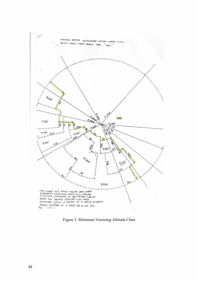
48
Figure 2. Minimum Vectoring Altitude Chart

49
Figure 3. Medan-Polonia Airport Chart (Jeppessen)
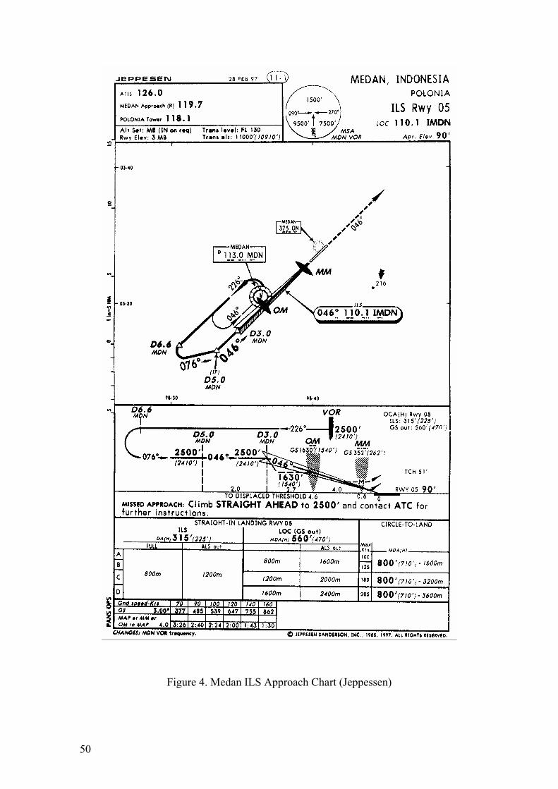
50
Figure 4. Medan ILS Approach Chart (Jeppessen)

51
Figure 5. A300-B4 Cutaway Drawing

52
Figure 6. A300-B4 Cockpit Instrumentation

53
Figure 7. A300-600 Cockpit Instrumentation

54
Figure 8. A300B4 Horizontal Situation Indicator
Figure 9. A300-600 Navigation Display

55
Figure 10. Initial impact tree, looking 060o M

56
Figure 11. Main crash site, looking 235o M
Figure 12. Main crash site- aft fuselage and empennage

57
Figure 13. Crash site (1), an area of abandoned rice paddy terraces

58
Figure 14. Crash site (2)

59
Figure 15. Crash site (3)

60
Figure 16. RH wing tip fairing and LE structure
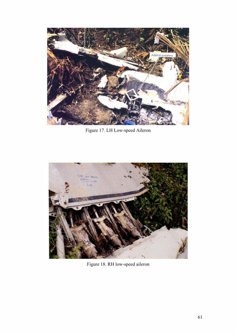
61
Figure 17. LH Low-speed Aileron
Figure 18. RH low-speed aileron

62
Figure 19. LH P&W JT9D engine, nose down
Figure 20. RH P&W JT9D engine, buried
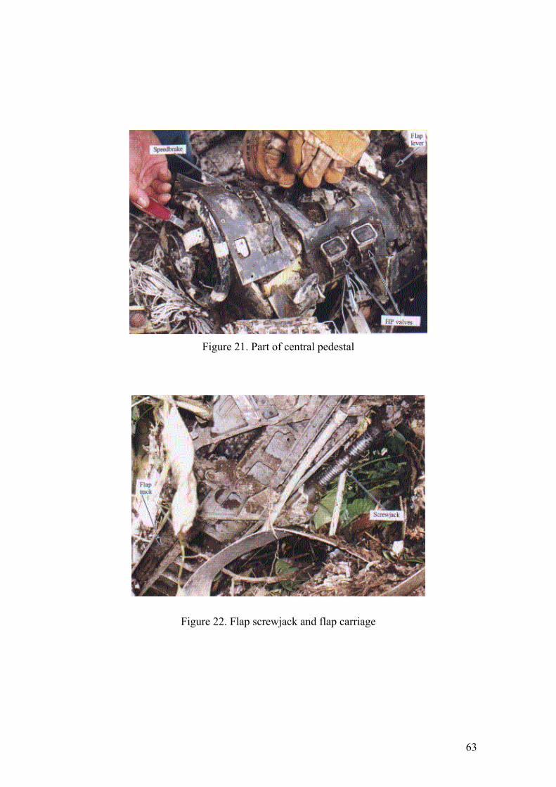
63
Figure 21. Part of central pedestal
Figure 22. Flap screwjack and flap carriage

64
Figure 23. Instrument – RMI
Figure 24. Instrument - Servo Altimeter

65
A B C D E F G H 2 A B C D E F G H 3 A B C D E F G H 4 A B C D E F G H 5 A B C D E F G H 6 A B C D E F G H 7 A B C D E F G H 8 A B C D E F G H 9 A B C D E F G H 10 A B C D E F G H 11 A B C D E F G H 12 A B C D E F G H 13 A B C D E F G H 14 A B C D E F G H 15 A B C D E F G H 16 A B C D E F G H 17 A B C D E F G H 18 A B C D E F G H 19 A B C D E F G H 20 A B C D E F G H 21 A B C D E F G H 22 A B C D E F G H 23 A B C D E F G H 24 A B C D E F G H 25 A B C D E F G H 26 A B C D E F G H 27 A B C D E F G H 28 A B C D E F G H 29 A B C D E F G H 30 A B C D E F G H 31 A B C D E F G H 32 A B C D E F G H 33 A B C D E F G H 34 A B C D E F G H 35 A B C D E F G H 36 A B C D E F G H 37 A B
C D E F
G H
Figure 25. Seat numbers of unidentified victims according to passenger list
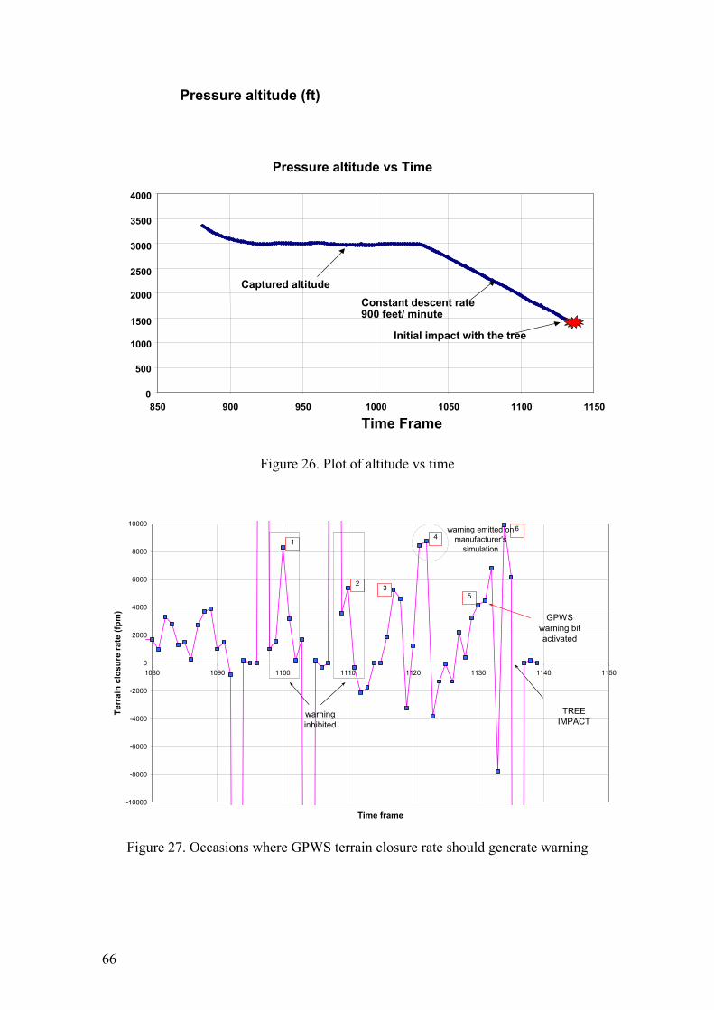
66
Figure 26. Plot of altitude vs time
-10000
-8000
-6000
-4000
-2000
0
2000
4000
6000
8000
10000
1080 1090 1100 1110 1120 1130 1140 1150
Time frame
Terr
ain
clos
ure
rate
(fpm
)
3
4
5
2
1
6
warning inhibited
warning emitted on manufacturer's
simulation
GPWS warning bit activated
TREE IMPACT
Figure 27. Occasions where GPWS terrain closure rate should generate warning
Pressure altitude vs Time
0
500
1000 1500
2000 2500
3000
3500
4000
850 900 950 1000 1050 1100 1150
Time Frame
Pressure altitude (ft)
Initial impact with the tree
Captured altitudeConstant descent rate 900 feet/ minute


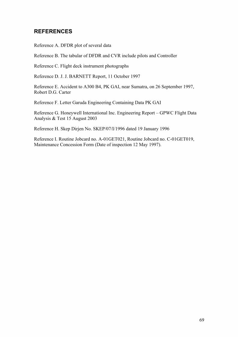
69
REFERENCES Reference A. DFDR plot of several data
Reference B. The tabular of DFDR and CVR include pilots and Controller
Reference C. Flight deck instrument photographs
Reference D. J. J. BARNETT Report, 11 October 1997
Reference E. Accident to A300 B4, PK GAI, near Sumatra, on 26 September 1997, Robert D.G. Carter
Reference F. Letter Garuda Engineering Containing Data PK GAI
Reference G. Honeywell International Inc. Engineering Report – GPWC Flight Data Analysis & Test 15 August 2003
Reference H. Skep Dirjen No. SKEP/07/I/1996 dated 19 January 1996
Reference I. Routine Jobcard no. A-01GET021, Routine Jobcard no. C-01GET019, Maintenance Concession Form (Date of inspection 12 May 1997).
70
APPENDICES
Appendix A. Wreckage Distribution
Appendix B. Transcript of the CVR recording
Appendix C. FDR Plot
Appendix D. NOTAM Class II no. 1-02/83
Appendix E. Approach Radar Vectoring Guidance for Visual and ILS Interception
Appendix F. Automatic Flight System – Relevant Longitudinal Modes
Appendix G. Automatic Flight System – Relevant Lateral Modes
Appendix H. GPWS Escape Maneuver Procedure

71
Appendix A. Wreckage Distribution
Figure A1. Wreckage distribution diagram

72
Table A1. Debris distribution
Ref
No
Distance
(m)
Bearing
(m from
rock)
X
(m)
Y
(m)
Description Remarks
1 43 192 -8.9 -42.1 Palm tree Reference plus limit
2 42 231 -32.6 -26.4 Twin burnt tree Reference plus limit
3 31 280 -30.5 5.4 Cut-off tree Reference plus limit
4 31 015 8.0 29.9 Large cut tree and fuel
control
Hit by left engine
5 28 316 -19.5 20.1 Twin tree ref point Reference plus limit
6 24 019 7.8 22.7 Engine (LH?) Intact and tail cone up
7 23 039 14.5 17.9 Limit of wreckage Knocked down vegetation
8 17 125 13.9 -9.8 Cockpit / flight deck area
9 43.5 226 -40.2 -72.3 Furthest extremity Portion of upper fuselage marked
'si' (part of word)
10 10 254 -9.6 -2.8 RH wing LE At engine mounting (RH)
11 23 254 -22.1 -6.3 RH wing tip
12 31 246 -28.3 -12.6 Emergency exit And portion of lower fuselage
13 51 244 -45.8 -22.4 Fuselage s'wall 3 windows (#109 - Airbus Industrie photo)
14 43 277 -42.7 5.2 Bulk cargo door (#115 - Airbus Industrie photo)
15 22 279 -21.7 3.4 Aft pressure bulkhead
16 28 318 -18.7 20.8 TE flap (LH?) (#118 - Airbus Industrie photo)
17 19 333 -8.6 16.9 Tail section (APU area) (#119 - Airbus Industrie photo)
18 21 353 -2.6 20.8 Lower tail fuselage (#120 - Airbus Industrie photo)
19 39 027 17.7 34.7 LH low speed aileron (#121 - Airbus Industrie photo)
20 51 027 23.2 45.4 Radome Item furthest away
21 12 035 6.9 9.8 Engine cowling (#122 - Airbus Industrie photo)
22 16 005 1.4 15.9 Tail cone with THS chafing plate
23 7 330 -3.5 6.1 LH MLG strut Gear retracted

73
Position of tree (1) at first impact and big broken tree (12) at the crash site
24
26
28
30
32
34
36
38
40
24 26 28 30 32 34 36 38 40 42
latitude (s)
longitude (s)
1
12
Figure A2, Coordinates of impact point and crash site
Table A2. Position of the first impact point and debris
Position of debris near first impact site
Points Item latitude (s)
longitude (s)
latitude (m)
longitude (m)
1 1st impact point 40.4 39.5 0.0 0.0 2 Aileron trailing edge 38.9 38.8 -46.3 -21.6 3 Wing trailing edge 38.5 38.8 -58.6 -21.6 4 Point at approximately 10 meters of the
second tree hit by the A/C 38.8 38.3 -49.4 -37.0
5 Aileron outboard end, leading edge part, trailing edge lower panel
37.8 38.6 -80.3 -27.8
6 Upper skin panel front spar 37 38.5 -104.9 -30.9 7 Leading edge part 36.8 38.3 -111.1 -37.0 8 Wing tip including primary structure 35.4 36.8 -154.3 -83.3 9
10 Rock used as reference 28.2 26.6 -376.6 -398.2 11 12 Big broken tree 29.1 27.3 -348.8 -376.6 13 14 Tree at the end of crash site 26.3 24.9 -435.2 -450.7 15 16 Structure part at the end of crash site 25.9 26.7 -447.6 -395.1

74

75

76

77
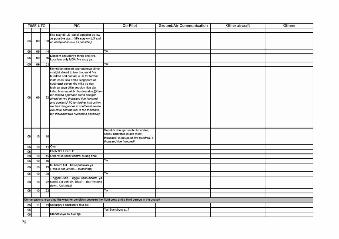
78

79

80

81

82

83

84

85

86

87
Appendix C. FDR Plot

88
Appendix B. NOTAM Class II no. 1-02/83

89
Appendix C. Approach Radar Vectoring Guidance for Visual and ILS Interception

90

91
Appendix D. Automatic Flight System – Relevant Longitudinal Modes
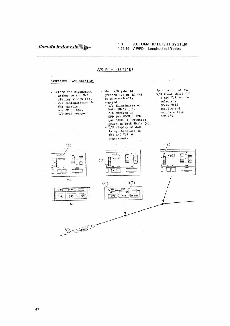
92

93
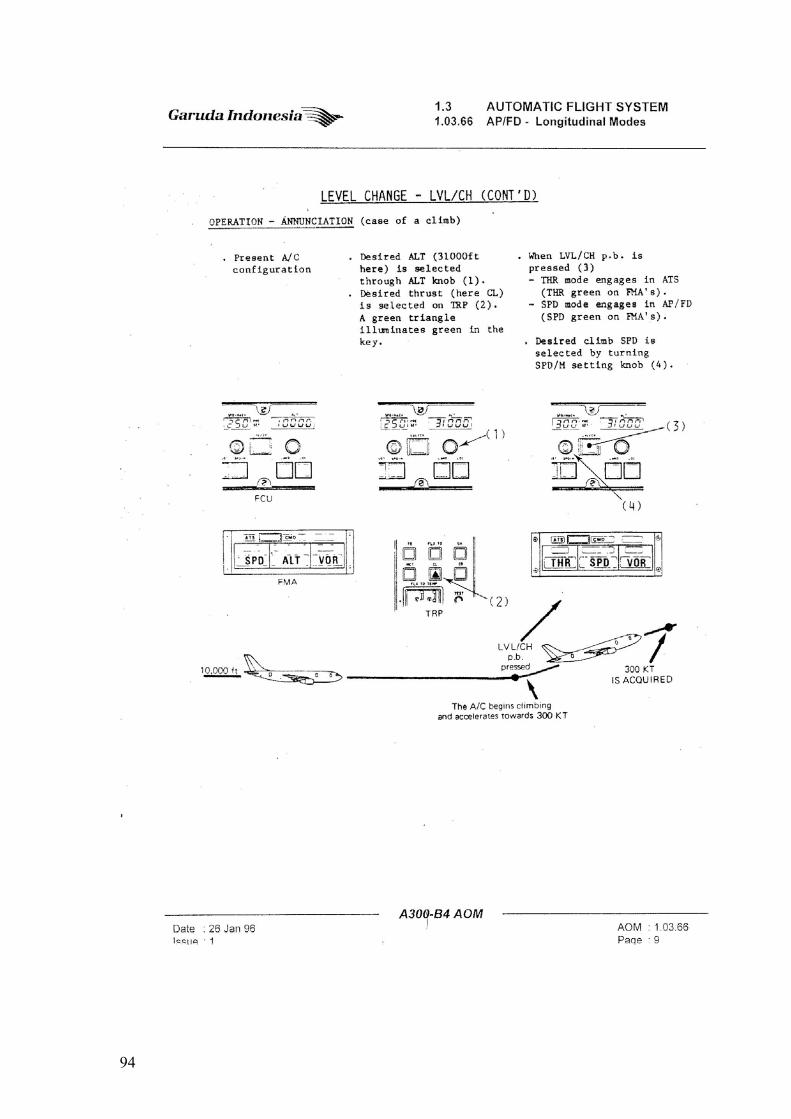
94
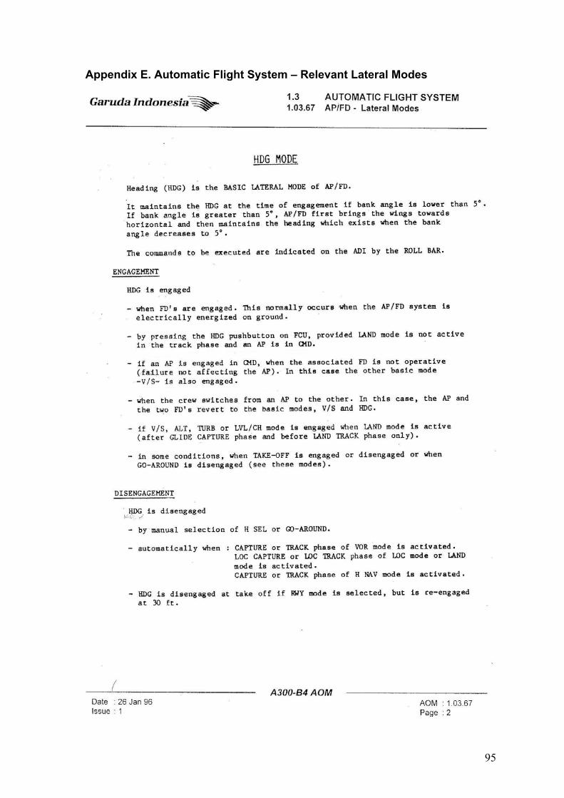
95
Appendix E. Automatic Flight System – Relevant Lateral Modes
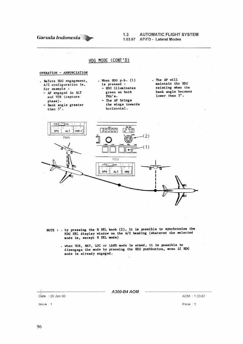
96

97
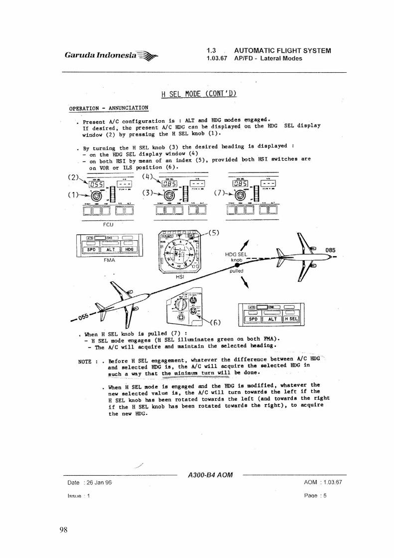
98

99
Appendix F. GPWS Escape Manouvre Procedure