Embed Size (px)
Citation preview

s1
Agilent 1100 Series Vacuum Degasser
Reference Manual

2 1100 Series VD Reference Manual
Notices© Agilent Technologies, Inc. 2002
No part of this manual may be reproduced in any form or by any means (including elec-tronic storage and retrieval or translation into a foreign language) without prior agree-ment and written consent from Agilent Technologies, Inc. as governed by United States and international copyright laws.
Manual Part NumberG1322-90004
EditionEdition 07/02
Printed in Germany
Agilent TechnologiesHewlett-Packard-Strasse 8 76337 Waldbronn, Germany
Software RevisionThis guide is valid for A.01.xx revisions of the Agilent 1100 Series Vacuum Degasser software, where xx refers to minor revisions of the software that do not affect the techni-cal accuracy of this guide.
WarrantyThe material contained in this docu-ment is provided “as is,” and is sub-ject to being changed, without notice, in future editions. Further, to the max-imum extent permitted by applicable law, Agilent disclaims all warranties, either express or implied, with regard to this manual and any information contained herein, including but not limited to the implied warranties of merchantability and fitness for a par-ticular purpose. Agilent shall not be liable for errors or for incidental or consequential damages in connec-tion with the furnishing, use, or per-formance of this document or of any information contained herein. Should Agilent and the user have a separate written agreement with warranty terms covering the material in this document that conflict with these terms, the warranty terms in the sep-arate agreement shall control.
Technology Licenses The hardware and/or software described in this document are furnished under a license and may be used or copied only in accor-dance with the terms of such license.
Restricted Rights LegendSoftware and technical data rights granted to federal government customers include only those rights customarily provided to end user Customers of Software. Agilent provides this customary commercial license in Software and technical data pursuant to FAR 12.211 (Technical Data) and FAR 12.212 (Computer Software) and, for Department of Defense purchases, DFARS 252.227-7015 (Technical Data - Commercial Items) and DFARS 227.7202-3 (Rights in Commercial Computer Software or Computer Software Documentation). If a federal government or other public sector Customer has a need for
rights not conveyed under these terms, it must negotiate with Agilent to establish acceptable terms in a written agreement executed by all relevant parties.
Safety Notices
CAUTION
A CAUTION notice denotes a haz-ard. It calls attention to an operat-ing procedure, practice, or the like that, if not correctly performed or adhered to, could result in damage to the product or loss of important data. Do not proceed beyond a CAUTION notice until the indicated conditions are fully understood and met.
WARNING
A WARNING notice denotes a hazard. It calls attention to an operating procedure, practice, or the like that, if not correctly per-formed or adhered to, could result in personal injury or death. Do not proceed beyond a WARNING notice until the indicated condi-tions are fully understood and met.
1100 Series VD Reference Manual 3
In This Guide…
1 Installing the Vacuum Degasser
How to install the vacuum degasser
2 Optimizing Performance
How to optimize the vacuum degasser to achieve best chromatographic results
3 Troubleshooting
Errors, their probable cause, and the action required to correct them
4 Repairing the Vacuum Degasser
Errors, their probable cause, and the action required to correct them
5 Parts and Materials
Instructions on how to repair the vacuum degasser
6 Theory of Operation
Detailed illustrations and listings for parts and materials identification
The vacuum degasser’s operation and electronics
7 Specifications
Performance specifications of the vacuum degasser

4 1100 Series VD Reference Manual

1100 Series VD Reference Manual 5
Contents
1 Installing the Vacuum Degasser
Site Requirements 10
Unpacking the Vacuum Degasser 13
Optimizing the Stack Configuration 15
Installing the Vacuum Degasser 17
Flow Connections to the Vacuum Degasser 19
Transporting the Vacuum Degasser 22
2 Optimizing Performance
Introduction to the Vacuum Degasser 24
When to Use a Vacuum Degasser? 25
Operation Modes of the Vacuum Degasser 26
Normal Operation Mode 1 27Normal Operation Mode 2 (Timing Mode) 27Continuous Mode 28Error Mode 28
Operational Hints for the Vacuum Degasser 29
Solvent Information 31
Prevent Blocking of Solvent Filters 32
3 Troubleshooting
Status Indicators 34
Hardware Symptoms 36
All Lamps are Off and the Vacuum Degasser Appears Dead 37
6 1100 Series VD Reference Manual
If the Status Indicator is Red 39If the Status Indicator is Yellow and the Vacuum Pump is not
Running 40If the Status Lamp is Yellow and the Vacuum Pump Runs
Continuously 41
4 Repairing the Vacuum Degasser
Overview of the Repair Procedures 46
Removing and Refitting the Top Cover 49Assembling the Main Cover 51Exchanging the Status Light Pipe 52
Overview of Internal Parts 53
Exchanging Internal Parts 54
Exchanging the Vacuum Chamber 55Exchanging the Vacuum Pump 56Exchanging the Solenoid Valve 58Exchanging the Degasser Control Assembly and the Sensor
Assembly 59
5 Parts and Materials
Vacuum Degasser Parts 62
Cover Parts 64
Sheet Metal Kit 65
Power and Status Light Pipes 66
Accessory Kit 67
Cable Overview 68
Remote Cables 69
Auxiliary Cable 71
6 Theory of Operation
How the Electronics Work 74
1100 Series VD Reference Manual 7
7 Specifications
Performance Specifications 80
A Safety Information
General Safety Information 82
Radio Interference 85
Sound Emission 86
Agilent Technologies on Internet 87
Index

8 1100 Series VD Reference Manual
9
Agilent 1100 Series Vacuum DegasserReference Manual
Agilent Technologies
1Installing the Vacuum Degasser
Site Requirements 10
Unpacking the Vacuum Degasser 13
Optimizing the Stack Configuration 15
Installing the Vacuum Degasser 17
Flow Connections to the Vacuum Degasser 19
Transporting the Vacuum Degasser 22
10 1100 Series VD Reference Manual
1 Installing the Vacuum Degasser
Site Requirements
A suitable environment is important to ensure optimum performance of the vacuum degasser.
Power Considerations
The vacuum degasser power supply has wide-ranging capability (see Table 1 on page 11). It accepts any line voltage in the range mentioned below. Consequently there is no voltage selector in the rear of the vacuum degasser. There are two externally accessible fuses, that protect the power supply.
Power Cords
Different power cords are offered as options with the vacuum degasser. The female end of each of the power cords is identical. It plugs into the power-input socket at the rear of the vacuum degasser. The male end of each of the power cords is different and designed to match the wall socket of a particular country or region.
WARNING Shock hazard or damage of your instrumentation can result, if the devices are connected to a line voltage higher than specified.
WARNING Never use cables other than the ones supplied by Agilent Technologies to ensure proper functionality and compliance with safety or EMC regulations.
WARNING Never operate your instrumentation from a power outlet that has no ground connection. Never use a power cord other than the power cord designed for your region.
Installing the Vacuum Degasser 1
1100 Series VD Reference Manual 11
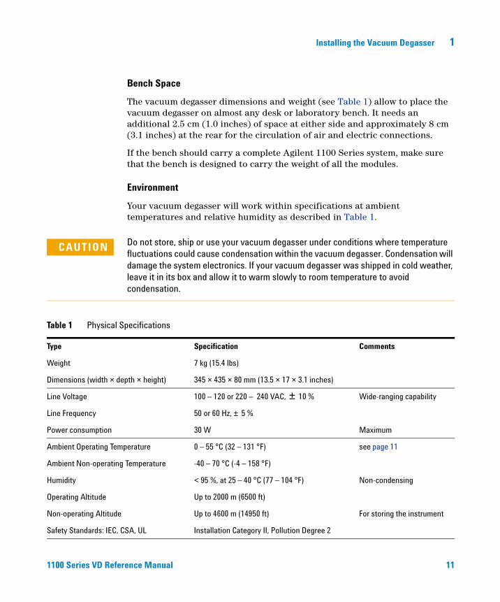
Bench Space
The vacuum degasser dimensions and weight (see Table 1) allow to place the vacuum degasser on almost any desk or laboratory bench. It needs an additional 2.5 cm (1.0 inches) of space at either side and approximately 8 cm (3.1 inches) at the rear for the circulation of air and electric connections.
If the bench should carry a complete Agilent 1100 Series system, make sure that the bench is designed to carry the weight of all the modules.
Environment
Your vacuum degasser will work within specifications at ambient temperatures and relative humidity as described in Table 1.
CAUTION Do not store, ship or use your vacuum degasser under conditions where temperature fluctuations could cause condensation within the vacuum degasser. Condensation will damage the system electronics. If your vacuum degasser was shipped in cold weather, leave it in its box and allow it to warm slowly to room temperature to avoid condensation.
Table 1 Physical Specifications
Type Specification Comments
Weight 7 kg (15.4 lbs)
Dimensions (width × depth × height) 345 × 435 × 80 mm (13.5 × 17 × 3.1 inches)
Line Voltage 100 – 120 or 220 – 240 VAC, ± 10 % Wide-ranging capability
Line Frequency 50 or 60 Hz, ± 5 %
Power consumption 30 W Maximum
Ambient Operating Temperature 0 – 55 °C (32 – 131 °F) see page 11
Ambient Non-operating Temperature -40 – 70 °C (-4 – 158 °F)
Humidity < 95 %, at 25 – 40 °C (77 – 104 °F) Non-condensing
Operating Altitude Up to 2000 m (6500 ft)
Non-operating Altitude Up to 4600 m (14950 ft) For storing the instrument
Safety Standards: IEC, CSA, UL Installation Category II, Pollution Degree 2
12 1100 Series VD Reference Manual
1 Installing the Vacuum Degasser
NOTE The Agilent 1100 Series vacuum degasser has been tested for evaporation of solvents into the atmosphere by an independent institute with approved methods. The tests were performed with Methanol (BIA Nr. 7810) and Acetonitrile (NIOSH, Nr. 1606). Evaporation of these solvents into the atmosphere when operating the degasser was below the limits of detection.
Installing the Vacuum Degasser 1
1100 Series VD Reference Manual 13
Unpacking the Vacuum Degasser
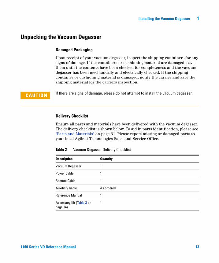
Damaged Packaging
Upon receipt of your vacuum degasser, inspect the shipping containers for any signs of damage. If the containers or cushioning material are damaged, save them until the contents have been checked for completeness and the vacuum degasser has been mechanically and electrically checked. If the shipping container or cushioning material is damaged, notify the carrier and save the shipping material for the carriers inspection.
Delivery Checklist
Ensure all parts and materials have been delivered with the vacuum degasser. The delivery checklist is shown below. To aid in parts identification, please see "Parts and Materials" on page 61. Please report missing or damaged parts to your local Agilent Technologies Sales and Service Office.
CAUTION If there are signs of damage, please do not attempt to install the vacuum degasser.
Table 2 Vacuum Degasser Delivery Checklist
Description Quantity
Vacuum Degasser 1
Power Cable 1
Remote Cable 1
Auxiliary Cable As ordered
Reference Manual 1
Accessory Kit (Table 3 on page 14)
1

14 1100 Series VD Reference Manual
1 Installing the Vacuum Degasser
Accessory Kit Contents
Table 3 Accessory Kit Contents G1322-68705
Description Part Number Quantity
Syringe*
* Reorder Number (pack of 10)
5062-8534 1
Syringe Adapter 9301-1337 1
Waste Tube**
** Reorder Number (5m)
5062-2463 1
Connecting Tubes labeled A to D G1322-67300 4
Installing the Vacuum Degasser 1
1100 Series VD Reference Manual 15
Optimizing the Stack Configuration
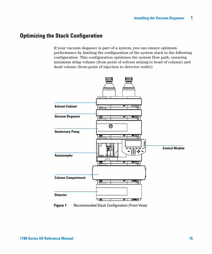
If your vacuum degasser is part of a system, you can ensure optimum performance by limiting the configuration of the system stack to the following configuration. This configuration optimizes the system flow path, ensuring minimum delay volume (from point of solvent mixing to head of column) and dead volume (from point of injection to detector outlet).
Figure 1 Recommended Stack Configuration (Front View)
Control Module
Detector
Column Compartment
Autosampler
Quaternary Pump
Vacuum Degasser
Solvent Cabinet
16 1100 Series VD Reference Manual
1 Installing the Vacuum Degasser
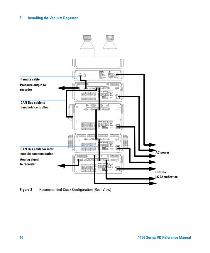
Figure 2 Recommended Stack Configuration (Rear View)
GPIB toLC ChemStation
AC power
Analog signal to recorder
Remote cable
CAN Bus cable to handheld controller
CAN Bus cable for inter module communication
Pressure output to recorder
Installing the Vacuum Degasser 1
1100 Series VD Reference Manual 17
Installing the Vacuum Degasser
1 Place the vacuum degasser on the bench.
2 Ensure the power switch on the front of the vacuum degasser is OFF (switch stands out).
3 Connect the power cable to the power connector at the rear of the vacuum degasser.
4 Connect the interface cable to the vacuum degasser. The interface cable (remote cable) is a one way connection to send a not-ready signal from the degasser to the other modules to shut down the whole system after an error condition of the degasser.
Parts required Vacuum degasserPower cableInterface cable as ordered, see "Cable Overview" on page 68
Preparation Locate bench spaceProvide power connectionsUnpack the vacuum degasser module
NOTE In an Agilent 1100 Series system, the individual modules are connected through a CAN cable. The Agilent 1100 Series vacuum degasser is an exception . The vacuum degasser can be connected via the APG remote connector to the other modules of the stack. The AUX output allows to monitor the vacuum pressure in the degasser chamber. An Agilent 1100 Series control module can be connected to the CAN bus at any of the modules in the system except for the degasser. The Agilent ChemStation can be connected to the system through one GPIB cable at any of the modules (except for the degasser), preferably at the detector. For more information about connecting the control module or Agilent ChemStation refer to the respective user manual.
18 1100 Series VD Reference Manual
1 Installing the Vacuum Degasser
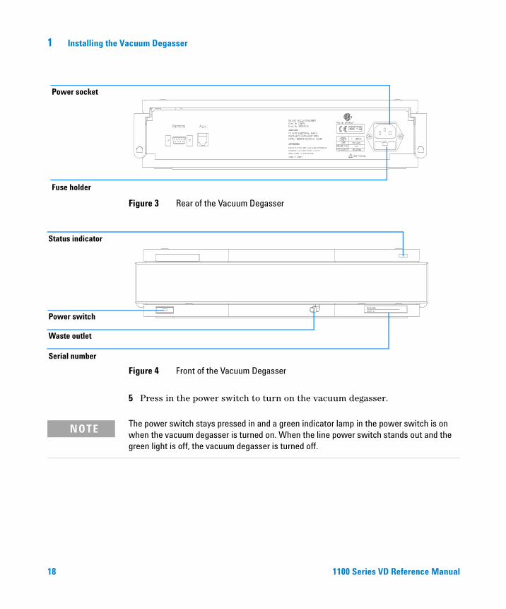
5 Press in the power switch to turn on the vacuum degasser.
Figure 3 Rear of the Vacuum Degasser
Figure 4 Front of the Vacuum Degasser
Power socket
Fuse holder
Power switch
Serial number
Waste outlet
Status indicator
NOTE The power switch stays pressed in and a green indicator lamp in the power switch is on when the vacuum degasser is turned on. When the line power switch stands out and the green light is off, the vacuum degasser is turned off.
Installing the Vacuum Degasser 1
1100 Series VD Reference Manual 19
Flow Connections to the Vacuum Degasser
1 Place solvent cabinet with the bottle(s) on top of the vacuum degasser.
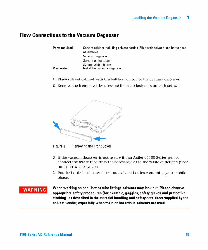
2 Remove the front cover by pressing the snap fasteners on both sides.
3 If the vacuum degasser is not used with an Agilent 1100 Series pump, connect the waste tube from the accessory kit to the waste outlet and place into your waste system.
4 Put the bottle head assemblies into solvent bottles containing your mobile phase.
Parts required Solvent cabinet including solvent bottles (filled with solvent) and bottle head assembliesVacuum degasserSolvent outlet tubesSyringe with adapter
Preparation Install the vacuum degasser
Figure 5 Removing the Front Cover
WARNING When working on capillary or tube fittings solvents may leak out. Please observe appropriate safety procedures (for example, goggles, safety gloves and protective clothing) as described in the material handling and safety data sheet supplied by the solvent vendor, especially when toxic or hazardous solvents are used.
20 1100 Series VD Reference Manual
1 Installing the Vacuum Degasser
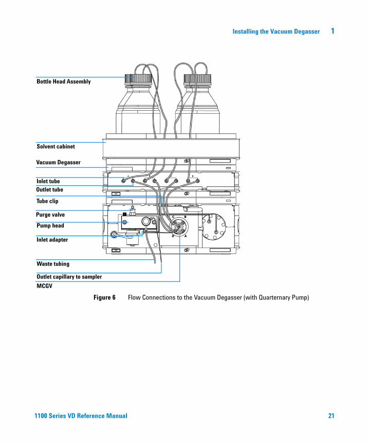
5 Connect the solvent tubes from the bottle head assemblies to the inlet connectors A to D (typically the left connection of the channel) of the vacuum degasser. Fix the tubes in the clips of the vacuum degasser.
6 Connect the outlet tubes to the output ports (typically right connection of the channel) of the vacuum degasser.
7 Prime the degasser before first use (see "Priming the Degasser" on page 29).
NOTE Atmospheric gases can diffuse through the tubing and dissolve in the mobile phase solvents. For best chromatographic results, keep the length of tubing between the vacuum degasser and your pump as short as possible.
Installing the Vacuum Degasser 1
1100 Series VD Reference Manual 21
Figure 6 Flow Connections to the Vacuum Degasser (with Quarternary Pump)
Bottle Head Assembly
Solvent cabinet
Vacuum Degasser
Outlet tubeInlet tube
Tube clip
Pump head
Inlet adapter
Waste tubing
Outlet capillary to sampler
MCGV
Purge valve
22 1100 Series VD Reference Manual
1 Installing the Vacuum Degasser
Transporting the Vacuum Degasser
1 Disconnect the solvent tubes from solvent inlets from front panel.
2 Disconnect one of the solvent tubes from your pump.
3 Connect syringe adapter to solvent tube of this solvent channel.
4 Push syringe adapter onto syringe.
5 Pull syringe plunger to draw solvent out of vacuum degasser and tubing. Continue to draw solvent into syringe until the solvent channel is completely empty.
6 Repeat step 2 through step 5 for the remaining solvent channels.
WARNING Drain any remaining solvents from the degassing channels before transporting the vacuum degasser.
23
Agilent 1100 Series Vacuum DegasserReference Manual
Agilent Technologies
2Optimizing Performance
Introduction to the Vacuum Degasser 24
When to Use a Vacuum Degasser? 25
Operation Modes of the Vacuum Degasser 26
Operational Hints for the Vacuum Degasser 29
Solvent Information 31
Prevent Blocking of Solvent Filters 32
24 1100 Series VD Reference Manual
2 Optimizing Performance
Introduction to the Vacuum Degasser
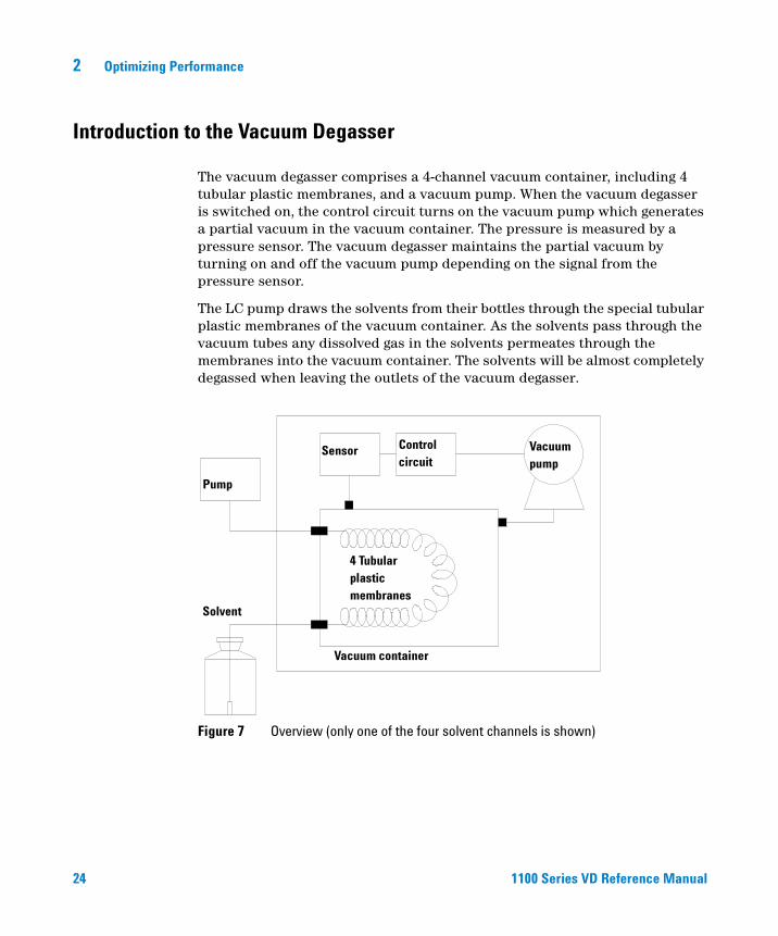
The vacuum degasser comprises a 4-channel vacuum container, including 4 tubular plastic membranes, and a vacuum pump. When the vacuum degasser is switched on, the control circuit turns on the vacuum pump which generates a partial vacuum in the vacuum container. The pressure is measured by a pressure sensor. The vacuum degasser maintains the partial vacuum by turning on and off the vacuum pump depending on the signal from the pressure sensor.
The LC pump draws the solvents from their bottles through the special tubular plastic membranes of the vacuum container. As the solvents pass through the vacuum tubes any dissolved gas in the solvents permeates through the membranes into the vacuum container. The solvents will be almost completely degassed when leaving the outlets of the vacuum degasser.
Figure 7 Overview (only one of the four solvent channels is shown)
Pump
Sensor Control circuit
Solvent
Vacuum container
4 Tubularplasticmembranes
Vacuumpump
Optimizing Performance 2
1100 Series VD Reference Manual 25
When to Use a Vacuum Degasser?
Pumps that mix the solvent on the low pressure side like the Agilent 1100 Series quaternary pump do need degassing and must be equipped with a vacuum degasser or alternative degassing systems (for example, helium). Isocratic pumps and high-pressure mixing pumps do not always require degassing. However for the following conditions the vacuum degasser is also recommended for an isocratic or a high pressure mixing pump:
• if your detector is used with maximum sensitivity in the low UV wavelength range,
• if your application requires optimum injection precision, or
• if your application requires highest retention time reproducibility (mandatory at flow rates below 0.5 ml/min),
• if your sample or detection is sensitive to dissolved oxygen in the mobile phase (degradation).
Generally a degasser should be used when negative effects due to dissolved gas in the mobile phase exceed the limits that are acceptable for the user. Negative effects that can be caused by dissolved gas are:
• Unstable flow due to unstable pumping conditions. This may result in a high ripple (unstable pressure at constant flow and with constant mobile phase composition) or high standard deviations of peak retention times and peak areas especially at low flow rates.
• Baseline noise on detectors that are sensitive to changes in the refractive index (e.g. RI detector or UV detector in the low UV range, both at maximum sensitivity).
• Sample degradation.
• Fluorescence Quenching due to dissolved oxygen.
• Baseline drift in electrochemical detectors due to dissolved oxygen especially in reduction mode.
26 1100 Series VD Reference Manual
2 Optimizing Performance
Operation Modes of the Vacuum Degasser
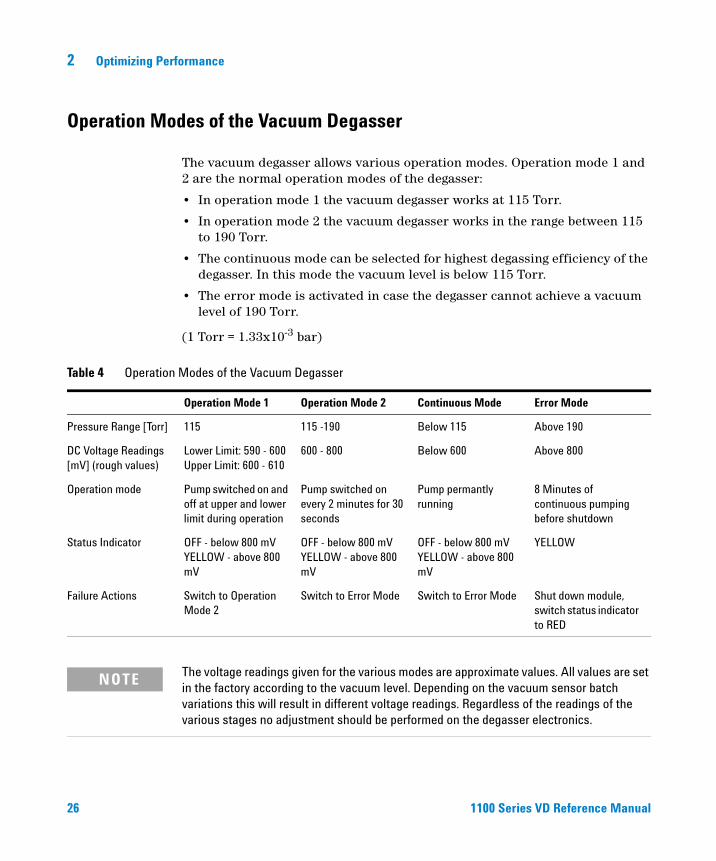
The vacuum degasser allows various operation modes. Operation mode 1 and 2 are the normal operation modes of the degasser:
• In operation mode 1 the vacuum degasser works at 115 Torr.
• In operation mode 2 the vacuum degasser works in the range between 115 to 190 Torr.
• The continuous mode can be selected for highest degassing efficiency of the degasser. In this mode the vacuum level is below 115 Torr.
• The error mode is activated in case the degasser cannot achieve a vacuum level of 190 Torr.
(1 Torr = 1.33x10⁻³ bar)
Table 4 Operation Modes of the Vacuum Degasser
Operation Mode 1 Operation Mode 2 Continuous Mode Error Mode
Pressure Range [Torr] 115 115 -190 Below 115 Above 190
DC Voltage Readings [mV] (rough values)
Lower Limit: 590 - 600 Upper Limit: 600 - 610
600 - 800 Below 600 Above 800
Operation mode Pump switched on and off at upper and lower limit during operation
Pump switched on every 2 minutes for 30 seconds
Pump permantly running
8 Minutes of continuous pumping before shutdown
Status Indicator OFF - below 800 mVYELLOW - above 800 mV
OFF - below 800 mVYELLOW - above 800 mV
OFF - below 800 mVYELLOW - above 800 mV
YELLOW
Failure Actions Switch to Operation Mode 2
Switch to Error Mode Switch to Error Mode Shut down module, switch status indicator to RED
NOTE The voltage readings given for the various modes are approximate values. All values are set in the factory according to the vacuum level. Depending on the vacuum sensor batch variations this will result in different voltage readings. Regardless of the readings of the various stages no adjustment should be performed on the degasser electronics.
Optimizing Performance 2
1100 Series VD Reference Manual 27
Normal Operation Mode 1
When the degasser is turned on, the vacuum pump runs and is connected to ambient through the solenoid valve. The solenoid valve activates about 15 seconds after turning on the degasser (you can hear it click). The vacuum pump then begins to pull a vacuum on the vacuum chamber. The voltage measurements begin to decrease rapidly. The yellow status LED turns off when the vacuum level reaches 190 Torr (DC voltage readings around 800mV). The normal operation mode vacuum level (115 Torr) is achieved when the DC voltage measures approximately 590 to 600 mV.After achieving the normal operation mode vacuum level, the solenoid valve turns off. The vacuum pump continues to run for a few seconds, then it turns off. When the DC voltage measurement rises back to approximately 600 to 610 mV, the turn on process begins again.If the vacuum level of normal operation mode one cannot be achieved within 8 minutes the instrument turns into normal operation mode 2.
Normal Operation Mode 2 (Timing Mode)
Under certain operational conditions (large amount of dissolved gas in mobile phase, high flow rates) the 115 Torr trigger level for operation mode 1 cannot be reached. The vacuum degasser automatically turns into operation mode 2. Normal operation mode 2 is a fixed timing mode. Every 2 minutes the degasser is turned on for 30 seconds. This assures a pressure level in the range from 115 to 190 Torr. The pressure signal measured with the auxiliary cable is in the range between 600 to 800 mV.If the vacuum level of normal operation mode two cannot be achieved within 8 minutes the instrument turns into error mode.
NOTE See "Preparing to Measure the Pressure Sensor Readings" on page 41 for setting up test meter connections to the degasser for reading the pressure sensor output.
28 1100 Series VD Reference Manual
2 Optimizing Performance
Continuous Mode
The continuous mode is activated either by switching SW1 on the main board to 1 (removal of cover is required, see "Removing and Refitting the Top Cover" on page 49, for identifying SW1, see "Overview of Internal Parts" on page 53), or by connecting pin 1 (white cable) and pin 3 (green cable) of the auxiliary cable to each other. When turning on the vacuum degasser the vacuum pump will run continuously. This will establish a vacuum level that is below the trigger level (600 mV / 115 Torr) of the normal operation mode 1. If the vacuum level of normal operation mode 2 cannot be achieved within 8 minutes the instrument turns into error mode.
When to use Continuous Mode
In continuous mode the vacuum pump runs continuously thus generating the highest degassing efficiency of the degasser. This mode is only recommended for very sensitive applications (e.g. RI detection).
Error Mode
The error level for the vacuum degasser is 190 Torr (approximately 800 mV). This level cannot be achieved when there is a failure in the degasser (for example, leaks, etc.). When the error level is exceeded the yellow status indicator lamp is turned on and the vacuum pump runs continuously. If the degasser cannot reach one of the normal operation modes within 8 minutes the status indicator turns red and the vacuum pump is turned off.
NOTE When set to continuous mode the life time of the vacuum pump will be significantly reduced.
Optimizing Performance 2
1100 Series VD Reference Manual 29
Operational Hints for the Vacuum Degasser
Priming the Degasser
The vacuum degasser can be primed either by drawing solvent through the degasser with a syringe or by pumping with the connected pump.
Priming the vacuum degasser with a syringe is recommended, when:
• vacuum degasser is used for the first time, or vacuum tubes are empty, or
• changing to solvents that are immiscible with the solvent currently in the vacuum tubes.
Priming the vacuum degasser by using the pump at high flow rate (3–5 ml/min) is recommended, when:
• pumping system was turned off for a length of time (for example, overnight) and if volatile solvent mixtures are used, or
• if solvents have been changed.
Priming with a Syringe
Before using a new degasser or new tubings for the first time:
1 Prime all tubings with at least 30 ml of iso-propanol no matter whether the channels will be used with organic mobile phase or with water.
If you are changing to a solvent that is immiscible with the solvent currently in the tubing continue as follows:
2 Replace the current solvent with iso-propanol, if current solvent is organic or with water, if current solvent is an inorganic buffer or contains salt.
3 Disconnect solvent outlet tube of the channel that is supposed to be primed from your pump.
4 Connect syringe adapter to solvent outlet tube.
5 Push syringe adapter onto syringe.
WARNING When opening capillary or tube fittings solvents may leak out. Please observe appropriate safety procedures (for example, goggles, safety gloves and protective clothing) as described in the material handling and safety data sheet supplied by the solvent vendor, especially when toxic or hazardous solvents are used.
30 1100 Series VD Reference Manual
2 Optimizing Performance
6 Pull syringe plunger to draw at least 30 ml of solvent through degasser and tubing.
7 Replace the priming solvent with the new solvent of your choice.
8 Pull syringe plunger to draw at least 30 ml of solvent through degasser and tubing.
9 Disconnect syringe adapter from solvent tube.
10 Connect solvent tube to your pump.
11 Repeat step 3 to step 10 for the other solvent channels.
Priming with the Pump
When the pumping system has been turned off for a certain time (for example, overnight) oxygen will rediffuse into the solvent channels between the vacuum degasser and the pump. Solvents containing volatile ingredients will slightly lose these, if left in the degasser without flow for a prolonged period of time. Therefore priming of the vacuum degasser and the pumping system is required before starting an application.
1 Open the purge valve of your pump and set flow rate to 5 ml/min.
2 Flush the vacuum degasser and all tubes with at least 30 ml of solvent.
3 Set flow to required value of your application and close the purge valve.
4 Pump for approximately 10 minutes before starting your application.
5 Repeat step 1 through step 4 with other channels, where needed.
NOTE When priming the vacuum degasser with a syringe the solvent is drawn through the degasser tubes very quickly. The solvent at the degasser outlet will therefore not be fully degassed. Pump for approximately 10 minutes with your selected flow rate before starting any application. This will allow the vacuum degasser to properly degas the solvent in the degasser tubes.
NOTE The pump should never be used for priming empty tubings (never let the pump run dry). Use the syringe to draw enough solvent for completely filling the tubings to the pump inlet before continueing to prime with the pump.

Optimizing Performance 2
1100 Series VD Reference Manual 31
Solvent Information
Always filter solvents through 0.4 µm filters, small particles can permanently block the capillaries. Avoid the use of the following steel-corrosive solvents:
• Solutions of alkali halides and their respective acids (for example, lithium iodide, potassium chloride, and so on).
• High concentrations of inorganic acids like sulfuric acid, especially at higher temperatures (replace, if your chromatography method allows, by phosphoric acid or phosphate buffer which are less corrosive against stainless steel).
• Halogenated solvents or mixtures which form radicals and/or acids, for example:
2CHCl3 + O2 → 2COCl2 + 2HCl
This reaction, in which stainless steel probably acts as a catalyst, occurs quickly with dried chloroform if the drying process removes the stabilizing alcohol.
• Chromatographic grade ethers, which can contain peroxides (for example, THF, dioxane, di-isopropylether) such ethers should be filtered through dry aluminium oxide which adsorbs the peroxides.
• Mixtures of carbon tetrachloride with 2-propanol or THF dissolve stainless steel.
32 1100 Series VD Reference Manual
2 Optimizing Performance
Prevent Blocking of Solvent Filters
Contaminated solvents or algae growth in the solvent bottle will reduce the lifetime of the solvent filter and will influence the performance of the pump. This is especially true for aqueous solvents or phosphate buffers (pH 4 to 7). The following suggestions will prolong lifetime of the solvent filter and will maintain the performance of the pump.
• Use sterile, if possible amber solvent bottles to slow down algae growth.
• Filter solvents through filters or membranes that remove algae.
• Exchange solvents every two days or refilter.
• If the application permits add 0.0001–0.001 M sodium azide to the solvent.
• Place a layer of argon on top of your solvent.
• Avoid exposure of the solvent bottles to direct sunlight.
Checking the Solvent Filters
The solvent filters are on the low-pressure side of the pumping system. A blocked filter therefore does not affect the pressure readings of the pump. The pressure readings cannot be used to indetify blocked filters. If the solvent cabinet is placed on top of the vacuum degasser the filter condition can be checked in the following way:
Remove the tubing at the inlet port of the vacuum degasser. If the filter is in good condition the solvent will freely drip out of the solvent tube (due to hydrostatic pressure). If the solvent filter is partly blocked no solvent or only very little solvent will drip out of the solvent tube.
Cleaning the Solvent Filters
• Remove the blocked solvent filter from the bottle-head assembly and place it in a beaker with concentrated nitric acid (35%) for one hour.
• Thoroughly flush the filter with bidistilled water (remove all nitric acid).
• Replace the filter.
NOTE Never use the system without solvent filter installed.
33
Agilent 1100 Series Vacuum DegasserReference Manual
Agilent Technologies
3Troubleshooting
Status Indicators 34
Hardware Symptoms 36
34 1100 Series VD Reference Manual
3 Troubleshooting
Status Indicators
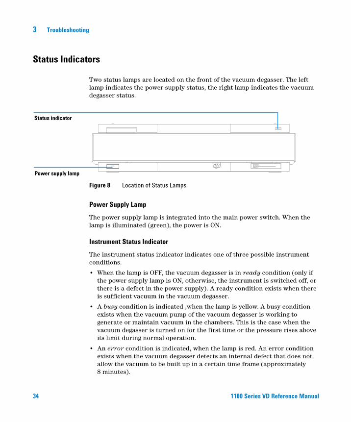
Two status lamps are located on the front of the vacuum degasser. The left lamp indicates the power supply status, the right lamp indicates the vacuum degasser status.
Power Supply Lamp
The power supply lamp is integrated into the main power switch. When the lamp is illuminated (green), the power is ON.
Instrument Status Indicator
The instrument status indicator indicates one of three possible instrument conditions.
• When the lamp is OFF, the vacuum degasser is in ready condition (only if the power supply lamp is ON, otherwise, the instrument is switched off, or there is a defect in the power supply). A ready condition exists when there is sufficient vacuum in the vacuum degasser.
• A busy condition is indicated ,when the lamp is yellow. A busy condition exists when the vacuum pump of the vacuum degasser is working to generate or maintain vacuum in the chambers. This is the case when the vacuum degasser is turned on for the first time or the pressure rises above its limit during normal operation.
• An error condition is indicated, when the lamp is red. An error condition exists when the vacuum degasser detects an internal defect that does not allow the vacuum to be built up in a certain time frame (approximately 8 minutes).
Figure 8 Location of Status Lamps
Power supply lamp
Status indicator
Troubleshooting 3
1100 Series VD Reference Manual 35
CAUTION If the error LED is on, there is either an internal leak in the vacuum system or an electronic failure. In case of an internal leak it is possible that solvent may enter the vacuum chamber and solvent may leak into the waste drain. To prevent any damage of the vacuum degasser, switch off the vacuum degasser and remove the solvent bottles from the solvent cabinet to stop any gravity-caused flow of solvent into the vacuum chamber.
36 1100 Series VD Reference Manual
3 Troubleshooting
Hardware Symptoms
In case of a problem with the vacuum system or the electronic control the vacuum degasser status lamp will be red. The vacuum degasser will generate an error output on the remote lines. This will shut down other system modules when connected via remote cable, see "Installing the Vacuum Degasser" on page 17. The vacuum degasser itself will not be able to generate any error messages in the system logbook of the Agilent 1100 Series. The following pages describe hardware symptoms which help you to isolate the cause of a hardware failure.
Troubleshooting 3
1100 Series VD Reference Manual 37
All Lamps are Off and the Vacuum Degasser Appears Dead
If all other modules in the system are on (power switch lamp is green) and are recognized by the connected user interface (module parameters can be set, module-specific screens appear, and so on), then do the following to determine the problem with the vacuum degasser:
• Ensure the power cable is connected to the degasser, and the power cable is connected to line power.
• Ensure the power switch on the front of the module is ON.
• Ensure the power fuses are OK.
The fuse holders are located on the rear panel of the vacuum degasser and are part of the power socket. Check the fuses, and change if necessary:
1 Switch off the power switch at the front of the instrument.
2 Remove the power cable from the power connector at the rear of the instrument.
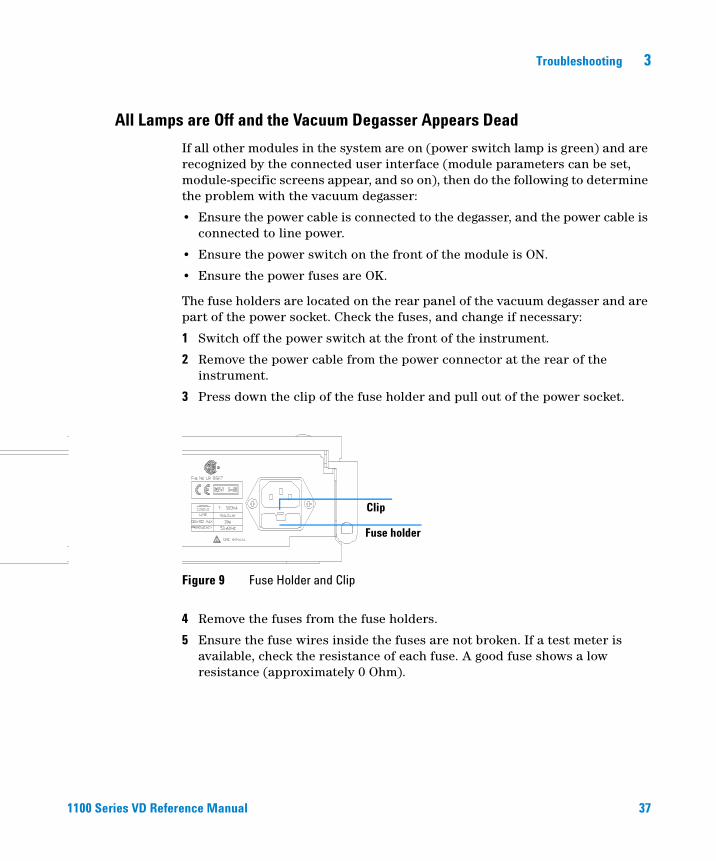
3 Press down the clip of the fuse holder and pull out of the power socket.
4 Remove the fuses from the fuse holders.
5 Ensure the fuse wires inside the fuses are not broken. If a test meter is available, check the resistance of each fuse. A good fuse shows a low resistance (approximately 0 Ohm).
Figure 9 Fuse Holder and Clip
Clip
Fuse holder
38 1100 Series VD Reference Manual
3 Troubleshooting
6 If a fuse is defective (wire broken or high resistance), insert a new fuse.
7 Reinsert the fuse holders and the power cable.
8 Switch on the power switch.
If the previous steps did not solve the problem, change the control assembly (see "Exchanging the Degasser Control Assembly and the Sensor Assembly" on page 59).
Troubleshooting 3
1100 Series VD Reference Manual 39
If the Status Indicator is Red
Sufficient vacuum is normally built up during the initial start-up and is maintained by turning on the vacuum pump whenever triggered by the vacuum sensor.
If the vacuum cannot be reached, or is lost faster than expected during operation, the vacuum degasser will be forced into an error state. Approximately 8 to 16 minutes after turning on the vacuum pump without reaching its normal operation modes the error LED is turned on and the vacuum pump and the solenoid will be disabled.
The error condition can be reset by turning the vacuum degasser off and on again. If the error condition persists the error will occur again after another 8 to 16 minutes.
The following described failure conditions will appear during the start-up procedure before the red error LED is turned on. Every power cycling of the degasser will give you 8 to 16 minutes of time to diagnose the failure conditions described on the following pages:
40 1100 Series VD Reference Manual
3 Troubleshooting
If the Status Indicator is Yellow and the Vacuum Pump is not Running
• Remove the top cover (see "Removing and Refitting the Top Cover" on page 49).
• Check the operation of the vacuum pump. Disconnect the vacuum tube from the sensor assembly to the vacuum chamber at the vacuum chamber (see "Overview of Internal Parts" on page 53) to adjust the pressure inside the vacuum chamber to ambient conditions. Switch the vacuum degasser off and on again. The vacuum pump should start immediately.
• Use a test meter to check for + 24 V DC on the connector CN2 of the control assembly between pin 1 and 2 ( see "Overview of Internal Parts" on page 53). This voltage is needed to operate the pump. If this voltage is low, exchange the control assembly (see "Exchanging the Degasser Control Assembly and the Sensor Assembly" on page 59).
• Check the resistance of the motor windings. The windings should have a resistance in the kOhm range (use a test meter to check resistance between red and blue, blue and black, black and red wires from connector CN2 to the pump). If the windings are broken or shortened replace the vacuum pump (see "Exchanging the Vacuum Pump" on page 56).
NOTE As long as there is sufficient vacuum in the chamber the pump will not be turned on until triggered by the vacuum sensor.
Troubleshooting 3
1100 Series VD Reference Manual 41
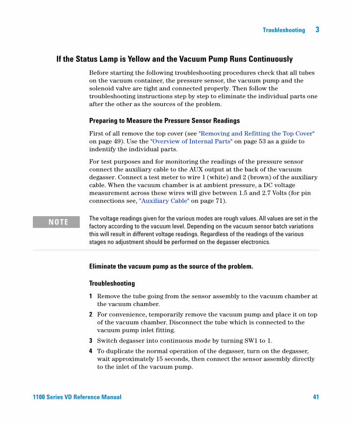
If the Status Lamp is Yellow and the Vacuum Pump Runs Continuously
Before starting the following troubleshooting procedures check that all tubes on the vacuum container, the pressure sensor, the vacuum pump and the solenoid valve are tight and connected properly. Then follow the troubleshooting instructions step by step to eliminate the individual parts one after the other as the sources of the problem.
Preparing to Measure the Pressure Sensor Readings
First of all remove the top cover (see "Removing and Refitting the Top Cover" on page 49). Use the "Overview of Internal Parts" on page 53 as a guide to indentify the individual parts.
For test purposes and for monitoring the readings of the pressure sensor connect the auxiliary cable to the AUX output at the back of the vacuum degasser. Connect a test meter to wire 1 (white) and 2 (brown) of the auxiliary cable. When the vacuum chamber is at ambient pressure, a DC voltage measurement across these wires will give between 1.5 and 2.7 Volts (for pin connections see, "Auxiliary Cable" on page 71).
Eliminate the vacuum pump as the source of the problem.
Troubleshooting
1 Remove the tube going from the sensor assembly to the vacuum chamber at the vacuum chamber.
2 For convenience, temporarily remove the vacuum pump and place it on top of the vacuum chamber. Disconnect the tube which is connected to the vacuum pump inlet fitting.
3 Switch degasser into continuous mode by turning SW1 to 1.
4 To duplicate the normal operation of the degasser, turn on the degasser, wait approximately 15 seconds, then connect the sensor assembly directly to the inlet of the vacuum pump.
NOTE The voltage readings given for the various modes are rough values. All values are set in the factory according to the vacuum level. Depending on the vacuum sensor batch variations this will result in different voltage readings. Regardless of the readings of the various stages no adjustment should be performed on the degasser electronics.
42 1100 Series VD Reference Manual
3 Troubleshooting
Results
A pressure reading below 500 mV indicates a good functioning vacuum pump.A pressure reading above 600 mV indicates that one of the pump chambers is contaminated or defective. In this case, disconnect the sensor tube and let the pump run without load for 5 minutes.Reconnect the sensor tube and repeat the measurement. If the correct vacuum is obtained the contamination has been flushed away and the vacuum pump is functioning correctly. If the pressure reading is still above 600 mV, the vacuum pump should be replaced (see "Exchanging the Vacuum Pump" on page 56).
5 Switch the degasser back to normal operation modes by turning SW1 back to 0.
6 Properly reconnect the tubings.
Eliminate the solenoid valve as the source of the problem.
Troubleshooting
1 Disconnect the outlet tubing from the solenoid valve (NC).
2 Remove the tube going from the sensor assembly to the vacuum chamber at the vacuum chamber.
3 For convenience remove the solenoid valve and place it on top of the vacuum chamber.
4 Connect the tubing from the sensor assembly directly to the outlet of the solenoid valve (NC).
5 Switch degasser into continuous mode by turning SW1 to 1.
Results
If the obtained pressure reading is similar to the result from the previous measurement (see above) when testing the pump (below 500 mV), the solenoid valve is functioning correctly.If the obtained pressure reading is different (above 500 mV) from the results obtained when testing the pump (see above), the solenoid valve is defective and needs replacing (see "Exchanging the Solenoid Valve" on page 58).
6 Switch the degasser back to normal operation modes by turning SW1 back to 0.
7 Properly reconnect the tubings and reinstall the solenoid valve.
Troubleshooting 3
1100 Series VD Reference Manual 43
Eliminate the vacuum chamber as the source of the problem.
Troubleshooting
1 Disconnect the outlet tube from the solenoid valve (NC) at the solenoid valve.
2 Disconnect the tube which is connected to the inlet of the vacuum pump.
3 Switch degasser into continuous mode by turning SW1 to 1.
4 To duplicate the normal operation of the degasser, turn on the degasser, wait approximately 15 seconds, then connect the outlet tube from the solenoid valve directly to the pump inlet.
Results
A pressure reading below 500 mV indicates a good working vacuum chamber. A pressure reading above 600 mV indicates a leak in the vacuum chamber. If necessary exchange the vacuum chamber (see "Exchanging the Vacuum Chamber" on page 55).
5 Switch the degasser back to normal operation modes by turning SW1 back to 0.
6 Properly reconnect the tubings and reinstall the pump.
Exchange the electronic control assembly
If the above described troubleshooting steps do not lead to an identification of the problem, replace the electronic control module with the pressure sensor assembly (see "Exchanging the Degasser Control Assembly and the Sensor Assembly" on page 59).

44 1100 Series VD Reference Manual
3 Troubleshooting
45
Agilent 1100 Series Vacuum DegasserReference Manual
Agilent Technologies
4Repairing the Vacuum Degasser
Overview of the Repair Procedures 46
Overview of Internal Parts 53
Exchanging Internal Parts 54
46 1100 Series VD Reference Manual
4 Repairing the Vacuum Degasser
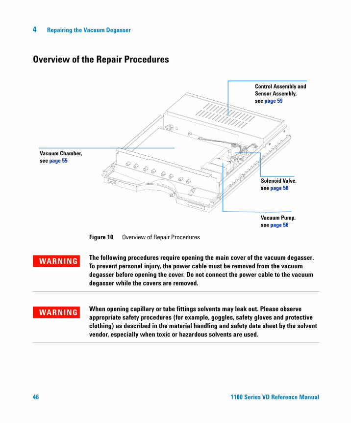
Overview of the Repair Procedures
Figure 10 Overview of Repair Procedures
Vacuum Chamber,see page 55
Control Assembly andSensor Assembly,see page 59
Vacuum Pump,see page 56
Solenoid Valve,see page 58
WARNING The following procedures require opening the main cover of the vacuum degasser. To prevent personal injury, the power cable must be removed from the vacuum degasser before opening the cover. Do not connect the power cable to the vacuum degasser while the covers are removed.
WARNING When opening capillary or tube fittings solvents may leak out. Please observe appropriate safety procedures (for example, goggles, safety gloves and protective clothing) as described in the material handling and safety data sheet by the solvent vendor, especially when toxic or hazardous solvents are used.
Repairing the Vacuum Degasser 4
1100 Series VD Reference Manual 47
The procedures in this section describe how to exchange internal parts. You must remove the vacuum degasser from the stack in order to open the main cover.
Cleaning the Instrument
The vacuum degasser case should be kept clean. Cleaning should be done with a soft cloth slightly dampened with water or a solution of water and a mild detergent. Do not use an excessively damp cloth that liquid can drip into the vacuum degasser.
CAUTION Electronic boards and components are sensitive to electrostatic discharge (ESD). In order to prevent damage always use an ESD protection (for example, the ESD wrist strap from the start up kit) when handling electronic boards and components.
CAUTION The plates of the sheet metal of the degasser are very thin. Although they have been deburred, they are still quite sharp, and it is possible that you may cut your hands or fingers if you slide them along the edges of the sheet metal of the enclosure.Therefore never slide your fingers along the edges of the enclosure.
WARNING Do not let liquid drip into the vacuum degasser. It could cause shock hazard and it could damage the vacuum degasser.
48 1100 Series VD Reference Manual
4 Repairing the Vacuum Degasser
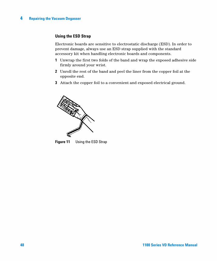
Using the ESD Strap
Electronic boards are sensitive to electrostatic discharge (ESD). In order to prevent damage, always use an ESD strap supplied with the standard accessory kit when handling electronic boards and components.
1 Unwrap the first two folds of the band and wrap the exposed adhesive side firmly around your wrist.
2 Unroll the rest of the band and peel the liner from the copper foil at the opposite end.
3 Attach the copper foil to a convenient and exposed electrical ground.
Figure 11 Using the ESD Strap

Repairing the Vacuum Degasser 4
1100 Series VD Reference Manual 49
Removing and Refitting the Top Cover
WARNING When opening capillary or tube fittings solvents may leak out. Please observe appropriate safety procedures (for example, goggles, safety gloves and protective clothing) as described in the material handling and safety data sheet by the solvent vendor, especially when toxic or hazardous solvents are used.
Tools required:
• Screwdriver Pozidriv #1
Preparations for this procedure:
• Switch off the vacuum degasser at the main power switch
• Disconnect the power cable and remote cable
• Disconnect all solvent tubes from the ports of the vacuum degasser
• Remove solvent cabinet from the vacuum degasser
• Remove vacuum degasser from the stack.
1 Remove the front panel.
2 Unclip the clips on the top cover . 3 Lift the cover away.
Clip
Clips
50 1100 Series VD Reference Manual
4 Repairing the Vacuum Degasser
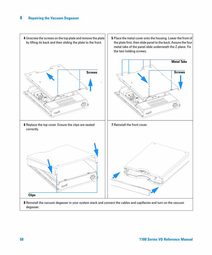
4 Unscrew the screws on the top plate and remove the plate by lifting its back and then sliding the plate to the front.
5 Place the metal cover onto the housing. Lower the front of the plate first, then slide panel to the back. Assure the four metal tabs of the panel slide underneath the Z-plane. Fix the two holding screws.
6 Replace the top cover. Ensure the clips are seated correctly.
7 Reinstall the front cover.
8 Reinstall the vacuum degasser in your system stack and connect the cables and capillaries and turn on the vacuum degasser.
Screws Screws
Metal Tabs
Clips

Repairing the Vacuum Degasser 4
1100 Series VD Reference Manual 51
Assembling the Main Cover
When required If cover is broken.Tools required None Parts required Cover kit 5062-8579 (includes base, top, left and right)
NOTE The cover kit contains all parts, but it is not assembled.
WARNING In case you insert the left or right side in the opposite position, you may not be able to remove the side from the top part.
1 Place the top part on the bench and insert the left and right side into the top part.
2 Replace the cover.
3 Replace the vacuum degasser in the stack and reconnect the cables and capillaries.
4 Turn on the vacuum degasser.
Front

52 1100 Series VD Reference Manual
4 Repairing the Vacuum Degasser
Exchanging the Status Light Pipe
When required If part is brokenTools required Screwdriver Pozidriv#1Part required Status light pipe 5041-8384
Preparation for this procedure:
• Remove the front cover and top cover, see "Removing and Refitting the Top Cover" on page 49.
1 The status light pipe is clipped into the top cover.
2 Replace the top cover, see "Removing and Refitting the Top Cover" on page 49.
Repairing the Vacuum Degasser 4
1100 Series VD Reference Manual 53
Overview of Internal Parts
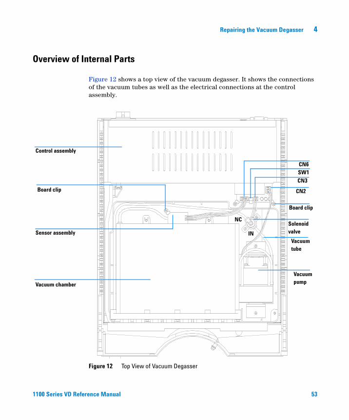
Figure 12 shows a top view of the vacuum degasser. It shows the connections of the vacuum tubes as well as the electrical connections at the control assembly.
Figure 12 Top View of Vacuum Degasser
Control assembly
Sensor assembly
Vacuum chamber
Solenoid valve
Vacuum pump
Board clip
Board clip
CN3
CN6
CN2
Vacuum tube
IN
NC
SW1
54 1100 Series VD Reference Manual
4 Repairing the Vacuum Degasser
Exchanging Internal Parts
WARNING The following procedures require opening the main cover of the detector. Always ensure the detector is disconnected from the line power when the main cover is removed. The security lever at the power input socket prevents the detector cover from being taken off when line power is still connected.
WARNING To disconnect the detector from line, unplug the power cord. The power supply still uses some power, even if the switch on the front panel is turned off.
WARNING When working with solvents please observe appropriate safety procedures (for example. goggles, safety gloves and protective clothing) as described in the material handling and safety data sheet by the solvent vendor, especially when using toxic or hazardous solvents.
NOTE The electronics of the detector will not allow operation of the detector when the top cover and the top foam are removed. A safety light switch on the main board will inhibit the operation of the fan immediately. Voltages for the other electronic components will be turned off after 30 seconds. The status lamp will light up red and an error will be logged into the logbook of the user interface. Always operate the detector with the top covers in place.
CAUTION Electronic boards and components are sensitive to electronic discharge (ESD). In order to prevent damage always use an ESD protection (for example, the ESD wrist strap from the accessory kit) when handling electronic boards and components, see "Using the ESD Strap" on page 48
WARNING Eye damage may result from directly viewing the light produced by the Deuterium lamp used in this product. Always turn off the deuterium lamp before removing it.
Repairing the Vacuum Degasser 4
1100 Series VD Reference Manual 55
Exchanging the Vacuum Chamber
1 Disconnect a solvent tube of one of the channels from your pump.
2 Connect syringe adapter to the disconnected solvent tube.
3 Push syringe adapter onto syringe.
4 Pull syringe plunger to draw solvent out of degasser and tubing. Continue to draw solvent into syringe until there is no solvent in the tubing.
5 Repeat step 1 to step 4 for other solvent channels.
6 Disconnect outlet tubes from the vacuum degasser.
7 Remove top cover, see "Removing and Refitting the Top Cover" on page 49.
8 Loosen the clip of the sensor board and remove it from its slot in the vacuum chamber (for identifying internal parts see "Overview of Internal Parts" on page 53).
9 Remove the two holding screws of the vacuum chamber.
10 Slide the vacuum chamber out of the front plate.
11 Disconnect the vacuum tubes from the vacuum chamber.
12 Reconnect the two vacuum tubes to the new vacuum chamber.
13 Slide the new vacuum chamber into the front plate and fix it with the two holding screws.
14 Slide the senor board back into the slots of the vacuum chamber and fix the clip.
15 Reconnect all inlet and outlet tubes to the vacuum chamber, see Figure 6 on page 21.
16 Refit the cover, see "Removing and Refitting the Top Cover" on page 49.
When required If internal membrane defective or vacuum chamber damaged Tools required Screwdriver Pozidriv #1Material Vacuum chamber, G1322-60001Preparation Disconnect the solvent inlet tubes at the degasser inlet ports
Remove the solvent cabinet from the vacuum degasser
WARNING Drain any remaining solvents from the degassing channels before removing the vacuum chamber from the vacuum degasser.
56 1100 Series VD Reference Manual
4 Repairing the Vacuum Degasser
Exchanging the Vacuum Pump
1 Remove Top Cover, see "Removing and Refitting the Top Cover" on page 49.
2 Disconnect vacuum pump cable from connector CN2 at the control assembly (for identifying internal parts see "Overview of Internal Parts" on page 53).
3 Using a Pozidriv screwdriver #1 loosen and remove the two holding screws of the vacuum pump.
4 Remove the fixing plates.
5 Lift the vacuum pump, disconnect the inlet tube (connected to the switching valve) and take the pump out of the unit.
6 Connect the tubing from the switching valve to the exchange vacuum pump inlet.
7 Place the vacuum pump in its position.
8 Place the fixing plates onto the rubber feet of the pump.
9 Insert the holding screws and fix them.
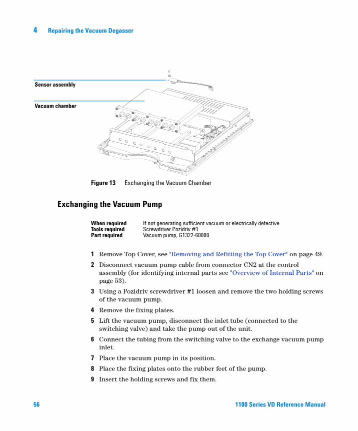
Figure 13 Exchanging the Vacuum Chamber
Vacuum chamber
Sensor assembly
When required If not generating sufficient vacuum or electrically defectiveTools required Screwdriver Pozidriv #1Part required Vacuum pump, G1322-60000
Repairing the Vacuum Degasser 4
1100 Series VD Reference Manual 57
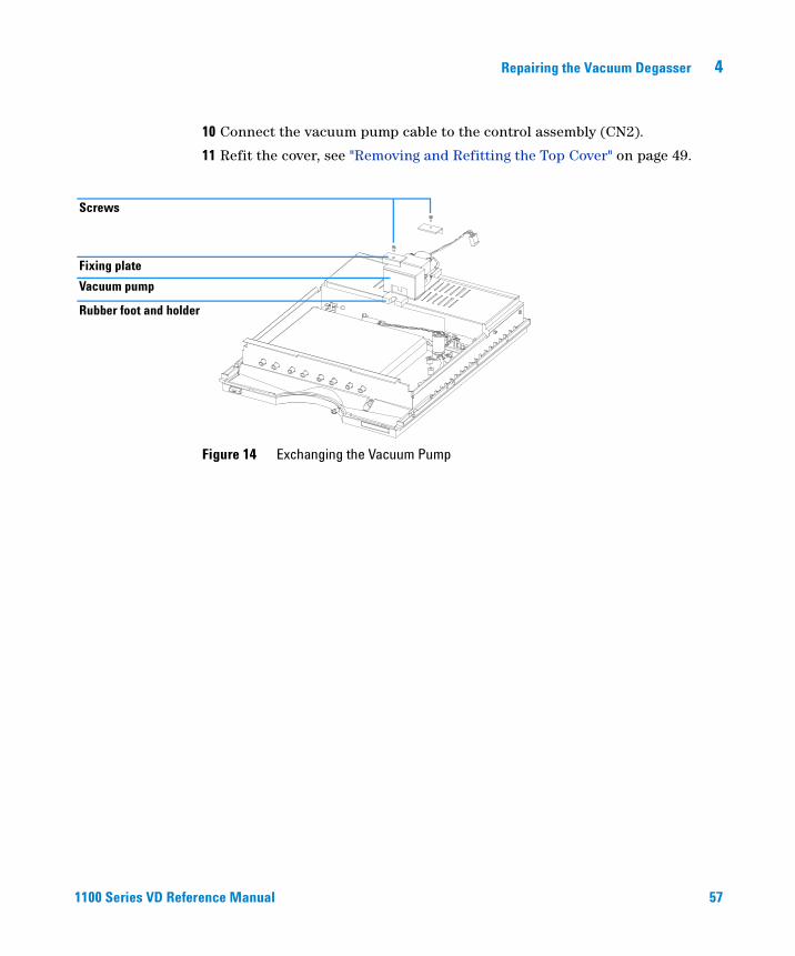
10 Connect the vacuum pump cable to the control assembly (CN2).
11 Refit the cover, see "Removing and Refitting the Top Cover" on page 49.
Figure 14 Exchanging the Vacuum Pump
Screws
Vacuum pump
Rubber foot and holder
Fixing plate
58 1100 Series VD Reference Manual
4 Repairing the Vacuum Degasser
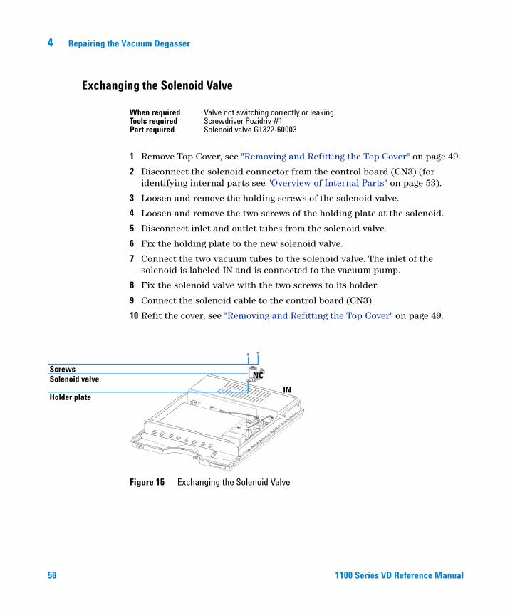
Exchanging the Solenoid Valve
1 Remove Top Cover, see "Removing and Refitting the Top Cover" on page 49.
2 Disconnect the solenoid connector from the control board (CN3) (for identifying internal parts see "Overview of Internal Parts" on page 53).
3 Loosen and remove the holding screws of the solenoid valve.
4 Loosen and remove the two screws of the holding plate at the solenoid.
5 Disconnect inlet and outlet tubes from the solenoid valve.
6 Fix the holding plate to the new solenoid valve.
7 Connect the two vacuum tubes to the solenoid valve. The inlet of the solenoid is labeled IN and is connected to the vacuum pump.
8 Fix the solenoid valve with the two screws to its holder.
9 Connect the solenoid cable to the control board (CN3).
10 Refit the cover, see "Removing and Refitting the Top Cover" on page 49.
When required Valve not switching correctly or leakingTools required Screwdriver Pozidriv #1Part required Solenoid valve G1322-60003
Figure 15 Exchanging the Solenoid Valve
Holder plate
Solenoid valveScrews
IN
NC
Repairing the Vacuum Degasser 4
1100 Series VD Reference Manual 59
Exchanging the Degasser Control Assembly and the Sensor Assembly
1 Remove Top Cover, see "Removing and Refitting the Top Cover" on page 49.
2 Disconnect all connectors at the control assembly board (for identifying internal parts see "Overview of Internal Parts" on page 53).
3 Loosen and remove the two holding clips at the control board of the control assembly.
4 Unclip the power switch light pipe at the degasser control assembly power switch.
5 Remove the four holding screws at the side panel — two at the left side, two on the right side of the vacuum degasser.
6 Lift the degasser control assembly out of the unit.
7 Remove the coupler from the control assembly and place it onto the power switch in the exchange control assembly.
8 Loosen the clip of the sensor board and remove it from its slot in the vacuum chamber.
9 Slide the new senor board into the slots of the vacuum chamber and the fix the clip.
10 Place a new degasser control assembly into the unit and fix with the four holding screws to the side panels.
11 Clip the power switch light pipe to the degasser control assembly power switch.
12 Replace the two holding clips and fix the holding screws.
When required No power available, vacuum pump or switching valve not activatedTools required Screwdriver Pozidriv #1Part required Degasser control assembly (includes the sensor assembly) G1322-66500
WARNING The degasser control assembly does not include any serviceable parts and should not be opened.
NOTE Sensor assembly and degasser control assembly are a matched pair and must be exchanged together.
60 1100 Series VD Reference Manual
4 Repairing the Vacuum Degasser
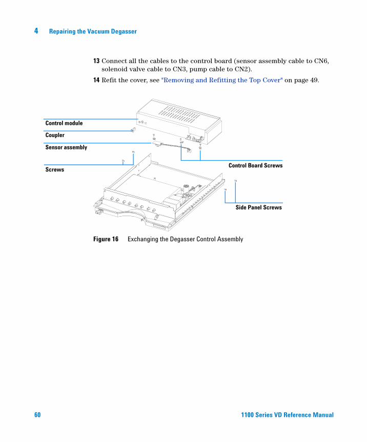
13 Connect all the cables to the control board (sensor assembly cable to CN6, solenoid valve cable to CN3, pump cable to CN2).
14 Refit the cover, see "Removing and Refitting the Top Cover" on page 49.
Figure 16 Exchanging the Degasser Control Assembly
Control module
Coupler
Screws
Side Panel Screws
Sensor assembly
Control Board Screws
61
Agilent 1100 Series Vacuum DegasserReference Manual
Agilent Technologies
5Parts and Materials
Vacuum Degasser Parts 62
Cover Parts 64
Sheet Metal Kit 65
Power and Status Light Pipes 66
Accessory Kit 67
Cable Overview 68
62 1100 Series VD Reference Manual
5 Parts and Materials
Vacuum Degasser Parts
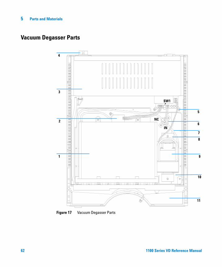
Figure 17 Vacuum Degasser Parts
1
2
3
5
6
7
8
9
11
4
10
IN
NC
SW1
Parts and Materials 5
1100 Series VD Reference Manual 63
Table 5 Repair Parts: Vacuum Degasser
Item Description Part Number
1 Vacuum chamber G1322-60001
2 Sensor assembly (included in the control assembly) no PN
3 Vacuum degasser control assembly G1322-66500
4 Fuse 500 mA 2110-0458
5 Board clip G1322-43100
6 Solenoid valve G1322-60003
7 Vacuum tubes G1322-60002
8 Fixing plate no PN
9 Vacuum pump G1322-60000
10 Leak tray G1322-44100
11 Leak pan, degasser 5042-1307
64 1100 Series VD Reference Manual
5 Parts and Materials
Cover Parts
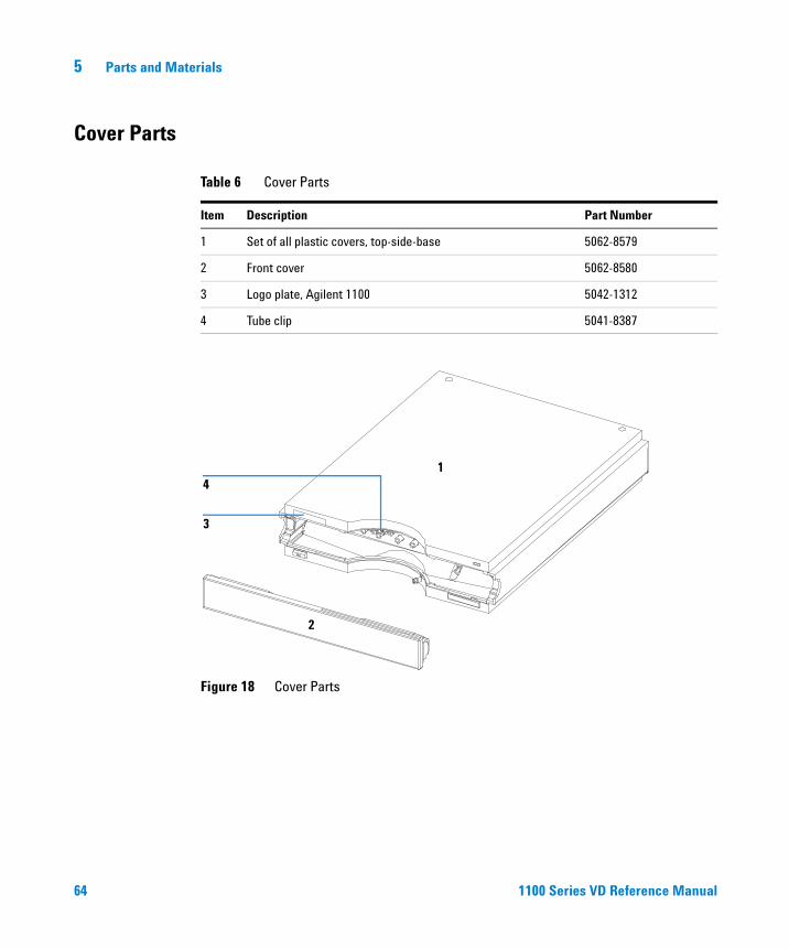
Table 6 Cover Parts
Item Description Part Number
1 Set of all plastic covers, top-side-base 5062-8579
2 Front cover 5062-8580
3 Logo plate, Agilent 1100 5042-1312
4 Tube clip 5041-8387
Figure 18 Cover Parts
1
2
3
4
Parts and Materials 5
1100 Series VD Reference Manual 65
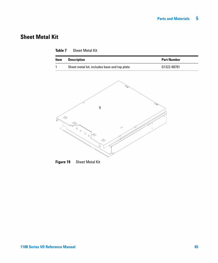
Sheet Metal Kit
Table 7 Sheet Metal Kit
Item Description Part Number
1 Sheet metal kit, includes base and top plate G1322-68701
Figure 19 Sheet Metal Kit
1
66 1100 Series VD Reference Manual
5 Parts and Materials
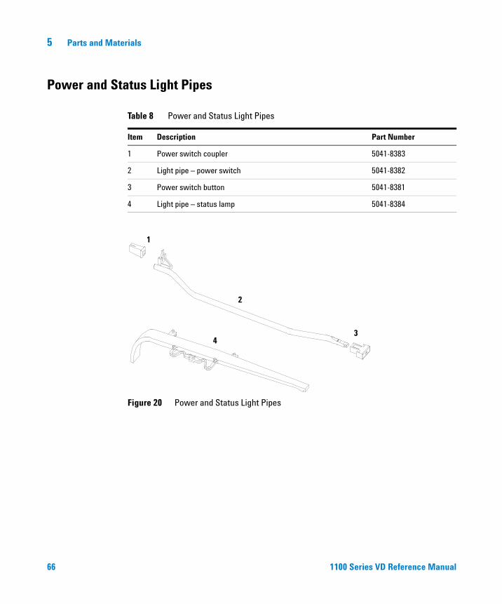
Power and Status Light Pipes
Table 8 Power and Status Light Pipes
Item Description Part Number
1 Power switch coupler 5041-8383
2 Light pipe – power switch 5041-8382
3 Power switch button 5041-8381
4 Light pipe – status lamp 5041-8384
Figure 20 Power and Status Light Pipes
1
2
34
Parts and Materials 5
1100 Series VD Reference Manual 67
Accessory Kit
Table 9 Accessory Kit G1322-68705
Item Description Part Number
1 Syringe*
* Reorder number (pack of 10)
**Reorder number (5m)
5062-8534
2 Syringe adapter 9301-1337
3 Solvent tubing kit (4 tubes degasser to pump) G1322-67300
4 Waste tube** 5062-2463
68 1100 Series VD Reference Manual
5 Parts and Materials
Cable Overview
WARNING Never use cables other than the ones supplied by Agilent Technologies to ensure proper functionality and compliance with safety or EMC regulations.
Table 10 Cable Overview
Type Description Part Number
Remote cables
Agilent 1100 modulesHP 1050 modulesHP 1046A FLD
5061-3378
General purpose 01046-60201
Auxiliary Agilent 1100 Series vacuum degasser G1322-61600
Parts and Materials 5
1100 Series VD Reference Manual 69
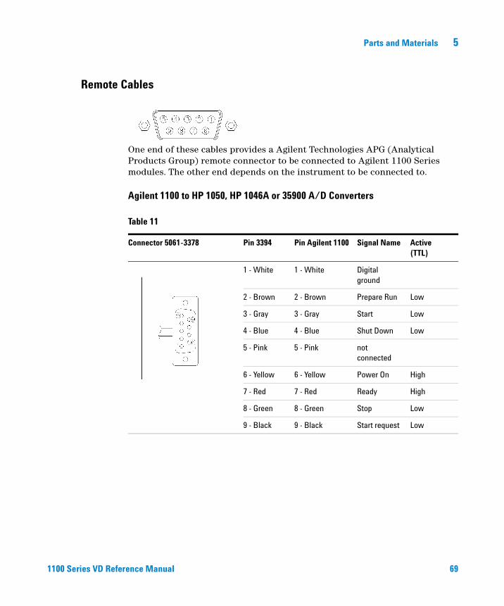
Remote Cables
One end of these cables provides a Agilent Technologies APG (Analytical Products Group) remote connector to be connected to Agilent 1100 Series modules. The other end depends on the instrument to be connected to.
Agilent 1100 to HP 1050, HP 1046A or 35900 A/D Converters
Table 11
Connector 5061-3378 Pin 3394 Pin Agilent 1100 Signal Name Active (TTL)
1 - White 1 - White Digital ground
2 - Brown 2 - Brown Prepare Run Low
3 - Gray 3 - Gray Start Low
4 - Blue 4 - Blue Shut Down Low
5 - Pink 5 - Pink not connected
6 - Yellow 6 - Yellow Power On High
7 - Red 7 - Red Ready High
8 - Green 8 - Green Stop Low
9 - Black 9 - Black Start request Low
70 1100 Series VD Reference Manual
5 Parts and Materials
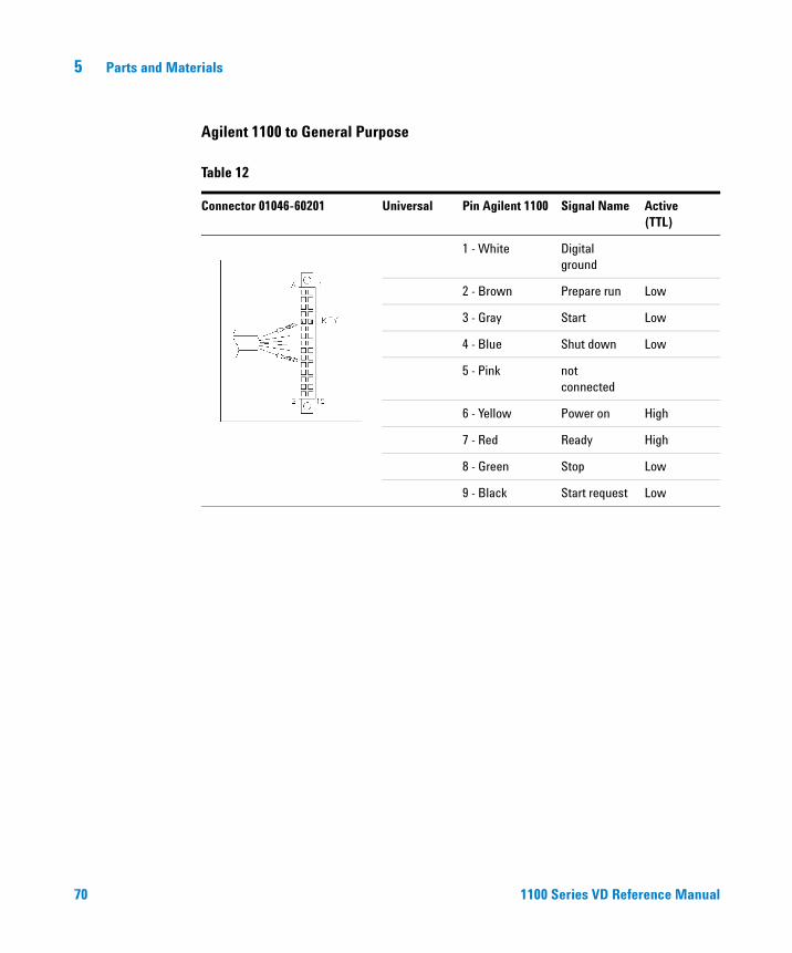
Agilent 1100 to General Purpose
Table 12
Connector 01046-60201 Universal Pin Agilent 1100 Signal Name Active (TTL)
1 - White Digital ground
2 - Brown Prepare run Low
3 - Gray Start Low
4 - Blue Shut down Low
5 - Pink not connected
6 - Yellow Power on High
7 - Red Ready High
8 - Green Stop Low
9 - Black Start request Low
Parts and Materials 5
1100 Series VD Reference Manual 71
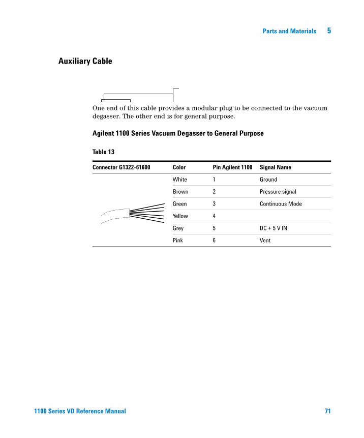
Auxiliary Cable
One end of this cable provides a modular plug to be connected to the vacuum degasser. The other end is for general purpose.
Agilent 1100 Series Vacuum Degasser to General Purpose
Table 13
Connector G1322-61600 Color Pin Agilent 1100 Signal Name
White 1 Ground
Brown 2 Pressure signal
Green 3 Continuous Mode
Yellow 4
Grey 5 DC + 5 V IN
Pink 6 Vent

72 1100 Series VD Reference Manual
5 Parts and Materials
73
Agilent 1100 Series Vacuum DegasserReference Manual
Agilent Technologies
6Theory of Operation
How the Electronics Work 74
74 1100 Series VD Reference Manual
6 Theory of Operation
How the Electronics Work
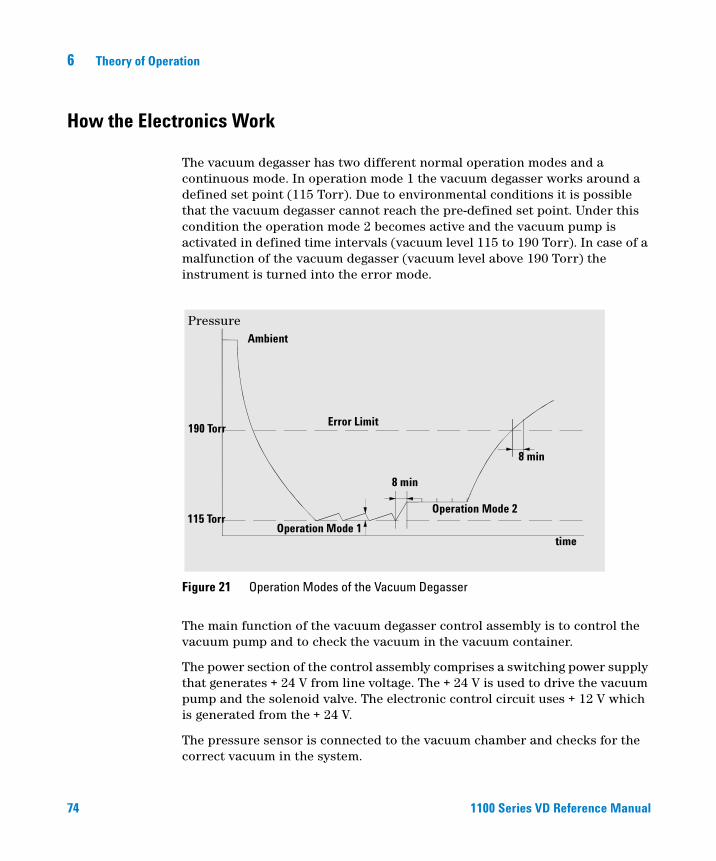
The vacuum degasser has two different normal operation modes and a continuous mode. In operation mode 1 the vacuum degasser works around a defined set point (115 Torr). Due to environmental conditions it is possible that the vacuum degasser cannot reach the pre-defined set point. Under this condition the operation mode 2 becomes active and the vacuum pump is activated in defined time intervals (vacuum level 115 to 190 Torr). In case of a malfunction of the vacuum degasser (vacuum level above 190 Torr) the instrument is turned into the error mode.
The main function of the vacuum degasser control assembly is to control the vacuum pump and to check the vacuum in the vacuum container.
The power section of the control assembly comprises a switching power supply that generates + 24 V from line voltage. The + 24 V is used to drive the vacuum pump and the solenoid valve. The electronic control circuit uses + 12 V which is generated from the + 24 V.
The pressure sensor is connected to the vacuum chamber and checks for the correct vacuum in the system.
Figure 21 Operation Modes of the Vacuum Degasser
time
Pressure
Error Limit
Operation Mode 2
Operation Mode 1
8 min
8 min
115 Torr
190 Torr
Ambient
Theory of Operation 6
1100 Series VD Reference Manual 75
The amplifier and comparator circuit determines the working range of the vacuum that has to be built up. When the vacuum degasser is turned on and the vacuum in the chamber is not within working range (above error limit of 190 Torr), the amplifier and comparator circuit sends a signal to the vacuum pump driver and the timers of the vacuum pump (timer 1) and the solenoid valve (timer 2).
The vacuum pump is turned on immediately while the solenoid valve closing is delayed by 15 seconds. This time delay allows the vacuum pump to start without load before it is connected to the vacuum chamber. The status indicator turns yellow when the pump is activated. The status lamp is turned off as soon as the vacuum is below the error limit.
When the vacuum in the chamber reaches its operation mode 1 (approximately 115 Torr) the amplifier and comparator circuit turns off the solenoid valve and the vacuum pump is turned off by a timer with a delay of 15 seconds.
As soon as the pressure sensor detects that the limit of the operation mode 1 has been exceeded (e.g. when dissolved gas from the solvent diffused into the vacuum chamber) the vacuum pump is started again as described before.
The pressure signal is available at the auxiliary output. It allows to monitor the vacuum system. The upper limit of operation mode 1 is 600 mV. Values below 600 mV on the pressure output indicate sufficient vacuum in the chamber. If the 600 mV are exceeded the vacuum pump will be started to keep the vacuum with in its working limit.
The amplifier and comparator circuit also activates the timer 3 when the vacuum in the vacuum chambers is below operation mode 1. The timer 3 is reset when operation mode 1 is reached within a maximum of 8 minutes. If operation mode 1 is not reached and the time (8 minutes) of timer 3 elapsed, the timer mode (operation mode 2) is activated. In this mode the vacuum pump is automatically turned on every 2 minutes for a time frame of 30 seconds. Timers 1 and 2 are activated as described earlier.
The error monitor continuously checks the error limit of the degasser (190 Torr). If the error limit is exceeded (for example, leak in chamber), the error timer is activated and the yellow status indicator lamp is turned on. The vacuum pump is turned on continuously. If the vacuum pump cannot reach either of its two operation modes within 8 minutes (error timer limit) the error driver is activated. The error driver will deactivate the vacuum pump and solenoid valve. The status lamp turns red and the error output on the remote connector will be activated.
76 1100 Series VD Reference Manual
6 Theory of Operation
The error output at the remote connector provides a contact closure (potential free open collector maximum load 35 V DC/50 mA) as long as the error condition is active. The error condition is set (closed) when the status light shows the error condition (red).
The continuous mode overwrites all other operation modes of the degasser. When activated (switch SW1 on the electronic board or via the auxiliary cable) the vacuum pump is forced into continuous mode and is turned on as long as the degasser is switched on.
Theory of Operation 6
1100 Series VD Reference Manual 77
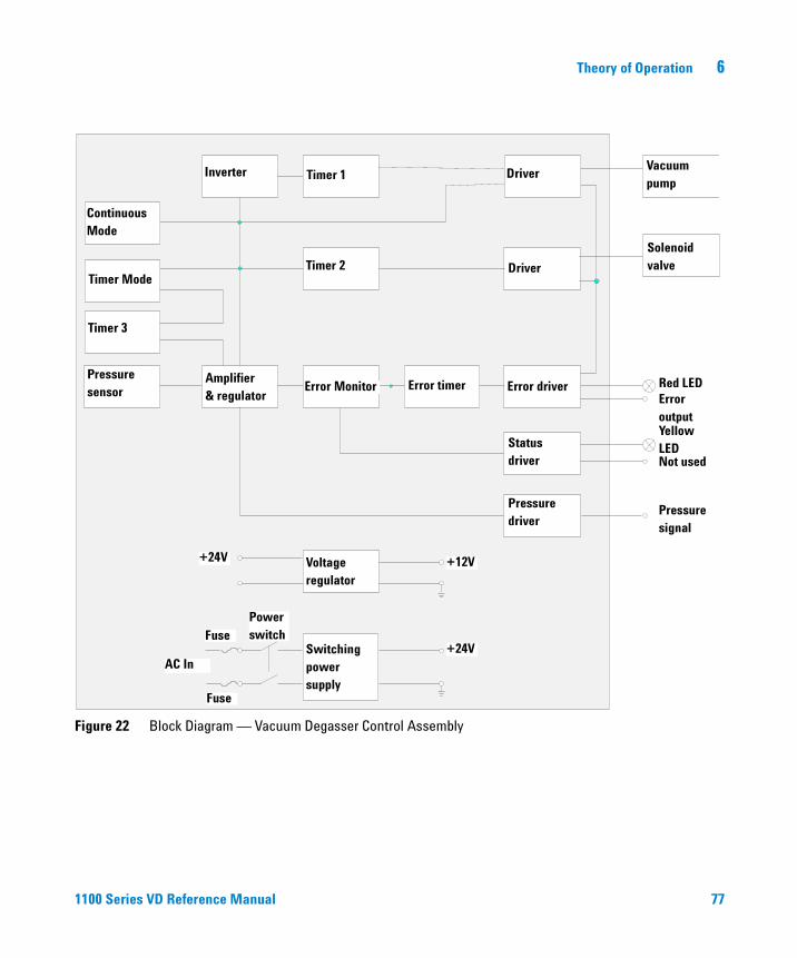
Figure 22 Block Diagram — Vacuum Degasser Control Assembly
Voltage regulator
Switching power supply
Pressure sensor
Amplifier& regulator
Error Monitor Error timer Error driver
Timer 2 Driver
Solenoid valve
Status driver
Pressure driver
Inverter Timer 1 DriverVacuum pump
Red LED
Yellow LED
Pressure signal
Error output
Not used
+24V +12V
+24VAC In
Fuse
FusePower switch
ContinuousMode
Timer Mode
Timer 3

78 1100 Series VD Reference Manual
6 Theory of Operation
79
Agilent 1100 Series Vacuum DegasserReference Manual
Agilent Technologies
7Specifications
Performance Specifications 80
80 1100 Series VD Reference Manual
7 Specifications
Performance Specifications
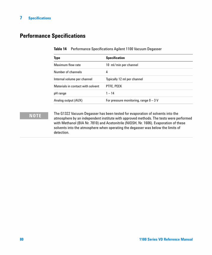
Table 14 Performance Specifications Agilent 1100 Vacuum Degasser
Type Specification
Maximum flow rate 10 ml/min per channel
Number of channels 4
Internal volume per channel Typically 12 ml per channel
Materials in contact with solvent PTFE, PEEK
pH range 1 – 14
Analog output (AUX) For pressure monitoring, range 0 – 3 V
NOTE The G1322 Vacuum Degasser has been tested for evaporation of solvents into the atmosphere by an independent institute with approved methods. The tests were performed with Methanol (BIA Nr. 7810) and Acetonitrile (NIOSH, Nr. 1606). Evaporation of these solvents into the atmosphere when operating the degasser was below the limits of detection.
81
Agilent 1100 Series Vacuum DegasserReference Manual
Agilent Technologies
ASafety Information
General Safety Information 82
Radio Interference 85
Sound Emission 86
Agilent Technologies on Internet 87
82 1100 Series VD Reference Manual
A Safety Information
General Safety Information
The following general safety precautions must be observed during all phases of operation, service, and repair of this instrument. Failure to comply with these precautions or with specific warnings elsewhere in this manual violates safety standards of design, manufacture, and intended use of the instrument. Agilent Technologies assumes no liability for the customer’s failure to comply with these requirements.
General
This is a Safety Class I instrument (provided with terminal for protective earthing) and has been manufactured and tested according to international safety standards.
Operation
Before applying power, comply with the installation section. Additionally the following must be observed.
Do not remove instrument covers when operating. Before the instrument is switched on, all protective earth terminals, extension cords, auto-transformers, and devices connected to it must be connected to a protective earth via a ground socket. Any interruption of the protective earth grounding will cause a potential shock hazard that could result in serious personal injury. Whenever it is likely that the protection has been impaired, the instrument must be made inoperative and be secured against any intended operation.
Make sure that only fuses with the required rated current and of the specified type (normal blow, time delay, and so on) are used for replacement. The use of repaired fuses and the short-circuiting of fuseholders must be avoided.
Some adjustments described in the manual, are made with power supplied to the instrument, and protective covers removed. Energy available at many points may, if contacted, result in personal injury.
Any adjustment, maintenance, and repair of the opened instrument under voltage should be avoided as much as possible. When inevitable, this should be carried out by a skilled person who is aware of the hazard involved. Do not
Safety Information A
1100 Series VD Reference Manual 83
attempt internal service or adjustment unless another person, capable of rendering first aid and resuscitation, is present. Do not replace components with power cable connected.
Do not operate the instrument in the presence of flammable gases or fumes. Operation of any electrical instrument in such an environment constitutes a definite safety hazard.
Do not install substitute parts or make any unauthorized modification to the instrument.
Capacitors inside the instrument may still be charged, even though the instrument has been disconnected from its source of supply. Dangerous voltages, capable of causing serious personal injury, are present in this instrument. Use extreme caution when handling, testing and adjusting.
When working with solvents please observe appropriate safety procedures (e.g. goggles, safety gloves and protective clothing) as described in the material handling and safety data sheet by the solvent vendor, especially when toxic or hazardous solvents are used.
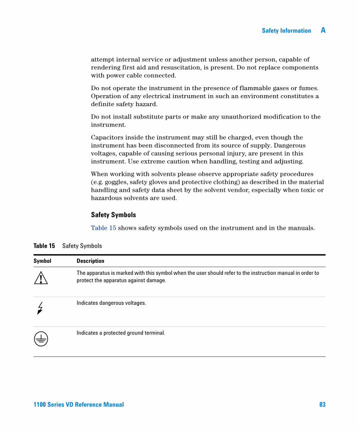
Safety Symbols
Table 15 shows safety symbols used on the instrument and in the manuals.
Table 15 Safety Symbols
Symbol Description
The apparatus is marked with this symbol when the user should refer to the instruction manual in order to protect the apparatus against damage.
Indicates dangerous voltages.
Indicates a protected ground terminal.
!
84 1100 Series VD Reference Manual
A Safety Information
WARNING A warning alerts you to situations that could cause physical injury or damage to the equipment. Do not proceed beyond a warning until you have fully understood and met the indicated conditions.
CAUTION A caution alerts you to situations that could cause a possible loss of data. Do not proceed beyond a caution until you have fully understood and met the indicated conditions.
Safety Information A
1100 Series VD Reference Manual 85
Radio Interference
Manufacturer’s Declaration
This is to certify that this equipment is in accordance with the Radio Interference Requirements of Directive FTZ 1046/1984. The German Bundespost was notified that this equipment was put into circulation, the right to check the series for compliance with the requirements was granted.
Test and Measurement
If test and measurement equipment is operated with equipment unscreened cables and/or used for measurements on open set-ups, the user has to assure that under operating conditions the radio interference limits are still met within the premises.
86 1100 Series VD Reference Manual
A Safety Information
Sound Emission
Manufacturer’s Declaration
This statement is provided to comply with the requirements of the German Sound Emission Directive of 18 January 1991.
This product has a sound pressure emission (at the operator position) < 70 dB.
• Sound Pressure Lp < 70 dB (A)
• At Operator Position
• Normal Operation
• According to ISO 7779:1988/EN 27779/1991 (Type Test)
Safety Information A
1100 Series VD Reference Manual 87
Agilent Technologies on Internet
For the latest information on products and services visit our worldwide web site on the Internet at:
http://www.agilent.com/go/chem

88 1100 Series VD Reference Manual
A Safety Information
1100 Series VD Reference Manual 89
Index
Aaccessory kit, 14, 48, 67Agilent on internet, 87algae growth, 32ambient non-operating temperature, 11ambient operating temperature, 11analog output, 80APG remote connector, 17AUX output, 17auxiliary cable, 41, 71
Bbench space, 11bottle, 19bottle-head assembly, 19busy condition, 34
Ccable, 68
auxiliary, 13, 41, 71CAN, 17GPIB, 17interface, 17power, 13, 37, 49remote, 13, 36, 68, 69
CAN cable, 17changing solvents, 29ChemStation, 17cleaning the instrument, 47connecting tube, 14control assembly, 59control circuit, 24cover, 64
Ddead volume, 15delay volume, 15delivery checklist, 13
dimensions, 11
Eelectronics
how does it work, 74electrostatic discharge (ESD), 47environment, 10, 11error condition, 34error state, 39exchanging
control asssembly, 59sensor assembly, 59solenoid valve, 58status light pipe, 52vacuum chamber, 55vacuum pump, 56
Fflow connections, 19flow rate, 80frequency range, 11front of the vacuum degasser, 18fuse, 10, 37
GGPIB cable, 17
Hhardware symptoms, 36highest injection precision, 25highest retention time reproducibility, 25humidity, 11
Iinstallation, 9, 17, 19interface cable, 17internal leak, 35
internet, 87introduction to the degasser, 24
Llaboratory bench, 11lamps
off, degasser appears dead, 37status indicator is red, 39status indicator is yellow, vacuum pump
not running, 40status indicator is yellow, vacuum pump
runs continuously, 41line frequency, 11line voltage, 11
Mmain cover, assembling, 51materials in contact with solvent, 80maximum flow rate, 80maximum sensitivity, 25
Nnon-operating altitude, 11number of channels, 80
Ooperating altitude, 11operational hints, 29
Pparts
accessory kit, 67cover, 64damaged, 13degasser, 62light pipes, 66missing, 13
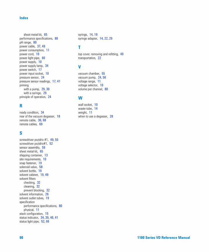
90 1100 Series VD Reference Manual
Index
sheet metal kit, 65performance specifications, 80pH range, 80power cable, 37, 49power consumption, 11power cord, 10power light pipe, 66power supply, 10power supply lamp, 34power switch, 17power-input socket, 10pressure sensor, 24pressure sensor readings, 17, 41priming
with a pump, 29, 30with a syringe, 29
principle of operation, 24
Rready condition, 34rear of the vacuum degasser, 18remote cable, 36, 68remote cables, 69
Sscrewdriver pozidriv #1, 49, 55screwdriver pozidriv#1, 52sensor assembly, 59sheet metal kit, 65shipping container, 13site requirements, 10snap fastener, 19solenoid valve, 58solvent bottle, 19solvent cabinet, 19, 49solvent filters
checking, 32cleaning, 32prevent blocking, 32
solvent information, 26solvent outlet tubes, 19specification
performance specifications, 80physical, 11
stack configuration, 15status indicator, 34, 39, 40, 41status light pipe, 52, 66
syringe, 14, 19syringe adapter, 14, 22, 29
Ttop cover, removing and refitting, 49transportation, 22
Vvacuum chamber, 55vacuum pump, 24, 56voltage range, 11voltage selector, 10volume per channel, 80
Wwall socket, 10waste tube, 14weight, 11when to use a degasser, 28

*G1322-90004**G1322-90004*G1322-90004
s1
In This Book
This manual contains technical reference information about the Agilent 1100 Series vacuum degasser. The manual describes the following:
• installation,
• optimizing performance,
• troubleshooting,
• repairing,
• parts and materials,
• theory of operation, and
• specifications.