Embed Size (px)
Citation preview
XCALI-97190 Revision B July 2007
Agilent®1100 Series
LC DevicesConnecting the Hardware and Triggering Data Acquisition

© 2007 Thermo Fisher Scientific Inc. All rights reserved.
Agilent® is a registered trademark of Agilent Technologies Inc. Hewlett-Packard® is a registered trademark of Hewlett-Packard Company. LCQ™, LTQ™, LXQ™, MSQ™, TSQ™, and Xcalibur™ are trademarks of Thermo Fisher Scientific Inc.
Thermo Fisher Scientific Inc. provides this document to its customers with a product purchase to use in the product operation. This document is copyright protected and any reproduction of the whole or any part of this document is strictly prohibited, except with the written authorization of Thermo Fisher Scientific Inc.
The contents of this document are subject to change without notice. All technical information in this document is for reference purposes only. System configurations and specifications in this document supersede all previous information received by the purchaser.
Thermo Fisher Scientific Inc. makes no representations that this document is complete, accurate or error-free and assumes no responsibility and will not be liable for any errors, omissions, damage or loss that might result from any use of this document, even if the information in the document is followed properly.
This document is not part of any sales contract between Thermo Fisher Scientific Inc. and a purchaser. This document shall in no way govern or modify any Terms and Conditions of Sale, which Terms and Conditions of Sale shall govern all conflicting information between the two documents.
Release history: First release February 2007, second release July 2007
For Research Use Only. Not regulated for medical or veterinary diagnostic use by U.S. Federal Drug Administration or other competent authorities.
C
Contents
Preface . . . . . . . . . . . . . . . . . . . . . . . . . . . . . . . . . . . . . . . . . . . . . . . . . . . . . . . . . . . . . . .vAbout This Guide. . . . . . . . . . . . . . . . . . . . . . . . . . . . . . . . . . . . . . . . . . . . . . . . vRelated Documentation . . . . . . . . . . . . . . . . . . . . . . . . . . . . . . . . . . . . . . . . . . . vSafety and Special Notices . . . . . . . . . . . . . . . . . . . . . . . . . . . . . . . . . . . . . . . . . vSafety Precautions . . . . . . . . . . . . . . . . . . . . . . . . . . . . . . . . . . . . . . . . . . . . . . . .viContacting Us . . . . . . . . . . . . . . . . . . . . . . . . . . . . . . . . . . . . . . . . . . . . . . . . . .vi
Chapter 1 Agilent Modules Supported by LC Devices Versions 2.0.2 and 2.1.0 . . . . . . . . . . .1
Chapter 2 Connecting the Hardware . . . . . . . . . . . . . . . . . . . . . . . . . . . . . . . . . . . . . . . . . . . . . . .3Ethernet Communication Kit . . . . . . . . . . . . . . . . . . . . . . . . . . . . . . . . . . . . . . . 3Installing a Network Card in an Agilent Module. . . . . . . . . . . . . . . . . . . . . . . . . 4Connecting the Ethernet Communication Cables . . . . . . . . . . . . . . . . . . . . . . . . 7Installing the External Contact Interface Board . . . . . . . . . . . . . . . . . . . . . . . . . . 8Connecting the Trigger Cable . . . . . . . . . . . . . . . . . . . . . . . . . . . . . . . . . . . . . . . 9
Chapter 3 Configuring the Autosampler for Contact Closure . . . . . . . . . . . . . . . . . . . . . . . . .11
Chapter 4 Triggering Data Acquisition with the Autosampler . . . . . . . . . . . . . . . . . . . . . . . .13
Chapter 5 Turning Off the Solvent Tracking Feature. . . . . . . . . . . . . . . . . . . . . . . . . . . . . . . . .15
Appendix A Upgrading an HP 1100 Series LC . . . . . . . . . . . . . . . . . . . . . . . . . . . . . . . . . . . . . . . .17
Index . . . . . . . . . . . . . . . . . . . . . . . . . . . . . . . . . . . . . . . . . . . . . . . . . . . . . . . . . . . . . . . .19
Thermo Scientific Agilent 1100 Series LC Devices Connecting the Hardware and Triggering Data Acquisition iii

P
Preface
About This GuideThis guide describes how to hardwire an Agilent® 1100 Series LC to a Thermo Scientific mass spectrometer and the data system computer, configure an Agilent autosampler for contact closure from within the Xcalibur Instrument Configuration program, and trigger data collection with an Agilent autosampler.
This guide also describes how to upgrade a Hewlett-Packard® 1100 Series LC to an Agilent 1100 Series LC with Ethernet communication.
Related DocumentationIn addition to this guide, Thermo Fisher Scientific provides Help available from within the Xcalibur software.
Safety and Special NoticesMake sure you follow the precautionary statements presented in this guide. The safety and other special notices appear in boxes.
Safety and special notices include the following:
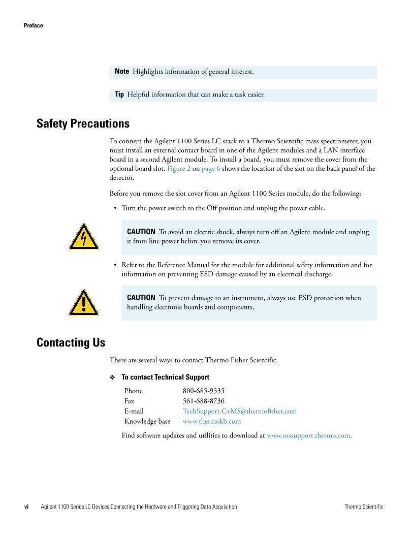
CAUTION Highlights hazards to humans, property, or the environment. Each CAUTION notice is accompanied by an appropriate CAUTION symbol.
CAUTION Highlights electric shock related hazards to human beings. Each electric shock notice is accompanied by the international High Voltage symbol.
IMPORTANT Highlights information necessary to prevent damage to software, loss of data, or invalid test results; or might contain information that is critical for optimal performance of the system.
Thermo Scientific Agilent 1100 Series LC Devices Connecting the Hardware and Triggering Data Acquisition v
Preface
vi
Safety PrecautionsTo connect the Agilent 1100 Series LC stack to a Thermo Scientific mass spectrometer, you must install an external contact board in one of the Agilent modules and a LAN interface board in a second Agilent module. To install a board, you must remove the cover from the optional board slot. Figure 2 on page 6 shows the location of the slot on the back panel of the detector.
Before you remove the slot cover from an Agilent 1100 Series module, do the following:
• Turn the power switch to the Off position and unplug the power cable.
• Refer to the Reference Manual for the module for additional safety information and for information on preventing ESD damage caused by an electrical discharge.
Contacting UsThere are several ways to contact Thermo Fisher Scientific.
To contact Technical Support
Find software updates and utilities to download at www.mssupport.thermo.com.
Note Highlights information of general interest.
Tip Helpful information that can make a task easier.
CAUTION To avoid an electric shock, always turn off an Agilent module and unplug it from line power before you remove its cover.
CAUTION To prevent damage to an instrument, always use ESD protection when handling electronic boards and components.
Phone 800-685-9535Fax 561-688-8736E-mail [email protected] base www.thermokb.com
Agilent 1100 Series LC Devices Connecting the Hardware and Triggering Data Acquisition Thermo Scientific
Preface
T
To contact Customer Service for ordering information
To suggest changes to documentation or to Help
• Fill out a reader survey online at www.thermo.com/lcms-techpubs.
• Send an e-mail message to the Technical Publications Editor at [email protected].
Phone 800-532-4752Fax 561-688-8731Web site www.thermo.com/finnigan
hermo Scientific Agilent 1100 Series LC Devices Connecting the Hardware and Triggering Data Acquisition vii

1
Agilent Modules Supported by LC Devices Versions 2.0.2 and 2.1.0
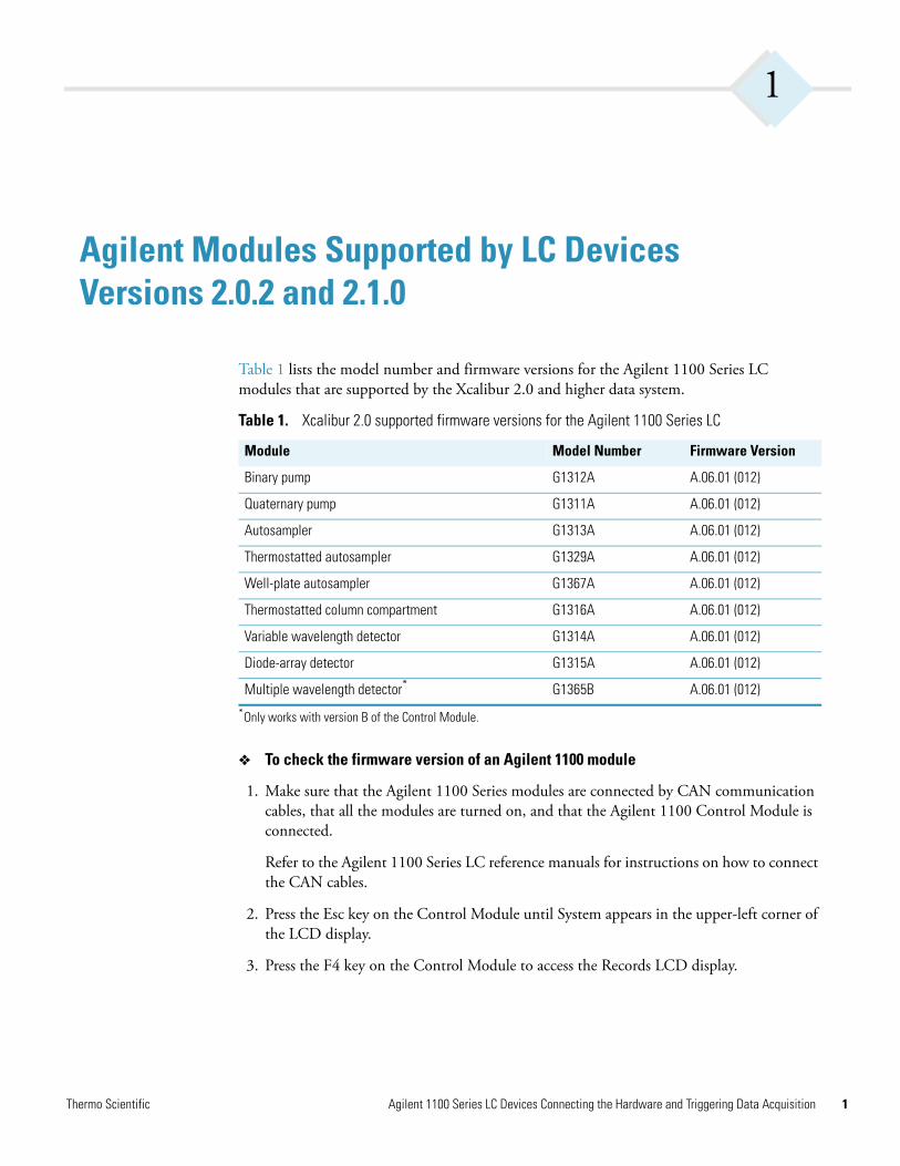
Table 1 lists the model number and firmware versions for the Agilent 1100 Series LC modules that are supported by the Xcalibur 2.0 and higher data system.
To check the firmware version of an Agilent 1100 module
1. Make sure that the Agilent 1100 Series modules are connected by CAN communication cables, that all the modules are turned on, and that the Agilent 1100 Control Module is connected.
Refer to the Agilent 1100 Series LC reference manuals for instructions on how to connect the CAN cables.
2. Press the Esc key on the Control Module until System appears in the upper-left corner of the LCD display.
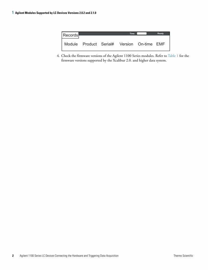
3. Press the F4 key on the Control Module to access the Records LCD display.
Table 1. Xcalibur 2.0 supported firmware versions for the Agilent 1100 Series LC
Module Model Number Firmware Version
Binary pump G1312A A.06.01 (012)
Quaternary pump G1311A A.06.01 (012)
Autosampler G1313A A.06.01 (012)
Thermostatted autosampler G1329A A.06.01 (012)
Well-plate autosampler G1367A A.06.01 (012)
Thermostatted column compartment G1316A A.06.01 (012)
Variable wavelength detector G1314A A.06.01 (012)
Diode-array detector G1315A A.06.01 (012)
Multiple wavelength detector*
*Only works with version B of the Control Module.
G1365B A.06.01 (012)
Thermo Scientific Agilent 1100 Series LC Devices Connecting the Hardware and Triggering Data Acquisition 1
1 Agilent Modules Supported by LC Devices Versions 2.0.2 and 2.1.0
2
4. Check the firmware versions of the Agilent 1100 Series modules. Refer to Table 1 for the firmware versions supported by the Xcalibur 2.0. and higher data system.
Records
Module Product Serial# Version On-time EMF
Time Ready
Agilent 1100 Series LC Devices Connecting the Hardware and Triggering Data Acquisition Thermo Scientific
2
Connecting the Hardware
This chapter describes how to install the interface boards, connect the Ethernet cables, and make the contact closure connections required to control an LC/MS system (Agilent LC/Thermo scientific MS) system from Xcalibur.
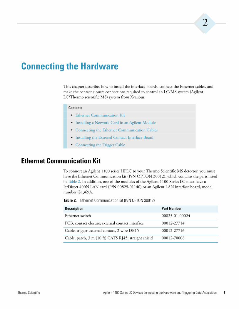
Ethernet Communication KitTo connect an Agilent 1100 series HPLC to your Thermo Scientific MS detector, you must have the Ethernet Communication kit (P/N OPTON 30012), which contains the parts listed in Table 2. In addition, one of the modules of the Agilent 1100 Series LC must have a JetDirect 400N LAN card (P/N 00825-01140) or an Agilent LAN interface board, model number G1369A.
Contents
• Ethernet Communication Kit
• Installing a Network Card in an Agilent Module
• Connecting the Ethernet Communication Cables
• Installing the External Contact Interface Board
• Connecting the Trigger Cable
Table 2. Ethernet Communication kit (P/N OPTON 30012)
Description Part Number
Ethernet switch 00825-01-00024
PCB, contact closure, external contact interface 00012-27714
Cable, trigger external contact, 2-wire DB15 00012-27716
Cable, patch, 3 m (10 ft) CAT5 RJ45, straight shield 00012-70008
Thermo Scientific Agilent 1100 Series LC Devices Connecting the Hardware and Triggering Data Acquisition 3
2 Connecting the HardwareInstalling a Network Card in an Agilent Module
4
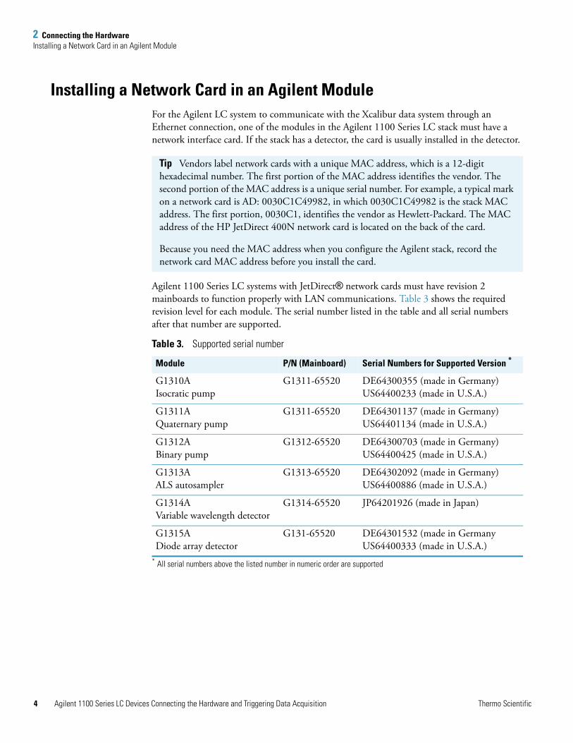
Installing a Network Card in an Agilent ModuleFor the Agilent LC system to communicate with the Xcalibur data system through an Ethernet connection, one of the modules in the Agilent 1100 Series LC stack must have a network interface card. If the stack has a detector, the card is usually installed in the detector.
Agilent 1100 Series LC systems with JetDirect® network cards must have revision 2 mainboards to function properly with LAN communications. Table 3 shows the required revision level for each module. The serial number listed in the table and all serial numbers after that number are supported.
Tip Vendors label network cards with a unique MAC address, which is a 12-digit hexadecimal number. The first portion of the MAC address identifies the vendor. The second portion of the MAC address is a unique serial number. For example, a typical mark on a network card is AD: 0030C1C49982, in which 0030C1C49982 is the stack MAC address. The first portion, 0030C1, identifies the vendor as Hewlett-Packard. The MAC address of the HP JetDirect 400N network card is located on the back of the card.
Because you need the MAC address when you configure the Agilent stack, record the network card MAC address before you install the card.
Table 3. Supported serial number
Module P/N (Mainboard) Serial Numbers for Supported Version *
* All serial numbers above the listed number in numeric order are supported
G1310A Isocratic pump
G1311-65520 DE64300355 (made in Germany)US64400233 (made in U.S.A.)
G1311A Quaternary pump
G1311-65520 DE64301137 (made in Germany)US64401134 (made in U.S.A.)
G1312A Binary pump
G1312-65520 DE64300703 (made in Germany)US64400425 (made in U.S.A.)
G1313A ALS autosampler
G1313-65520 DE64302092 (made in Germany)US64400886 (made in U.S.A.)
G1314A Variable wavelength detector
G1314-65520 JP64201926 (made in Japan)
G1315A Diode array detector
G131-65520 DE64301532 (made in GermanyUS64400333 (made in U.S.A.)
Agilent 1100 Series LC Devices Connecting the Hardware and Triggering Data Acquisition Thermo Scientific
2 Connecting the HardwareInstalling a Network Card in an Agilent Module
T
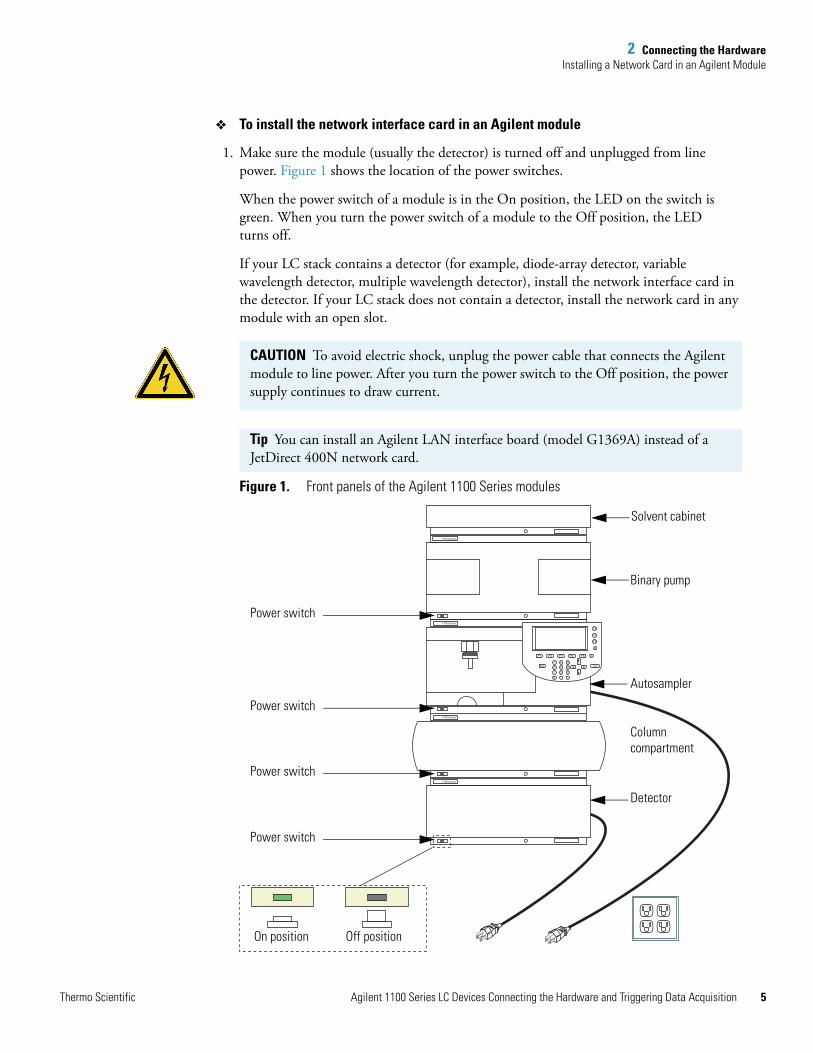
To install the network interface card in an Agilent module
1. Make sure the module (usually the detector) is turned off and unplugged from line power. Figure 1 shows the location of the power switches.
When the power switch of a module is in the On position, the LED on the switch is green. When you turn the power switch of a module to the Off position, the LED turns off.
If your LC stack contains a detector (for example, diode-array detector, variable wavelength detector, multiple wavelength detector), install the network interface card in the detector. If your LC stack does not contain a detector, install the network card in any module with an open slot.
Figure 1. Front panels of the Agilent 1100 Series modules
CAUTION To avoid electric shock, unplug the power cable that connects the Agilent module to line power. After you turn the power switch to the Off position, the power supply continues to draw current.
Tip You can install an Agilent LAN interface board (model G1369A) instead of a JetDirect 400N network card.
1100 Series
1100 Series
1100 Series
1100 Series
F1
F8
i
m
F7
F6
F2 F3 F4 F5
987
5 64
1 2 3
0 . -
Esc Enter◄
◄
Detector
Power switch
Column compartment
Autosampler
Binary pump
Solvent cabinet
Power switch
Power switch
Power switch
On position Off position
hermo Scientific Agilent 1100 Series LC Devices Connecting the Hardware and Triggering Data Acquisition 5
2 Connecting the HardwareInstalling a Network Card in an Agilent Module
6
2. To prevent damage to the interface board, ensure that you are using ESD protection. For more information on preventing damage caused by an electric discharge, refer to the Reference Manual for the Agilent module.
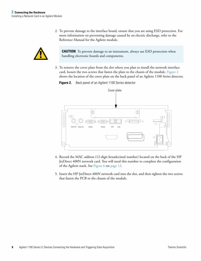
3. To remove the cover plate from the slot where you plan to install the network interface card, loosen the two screws that fasten the plate to the chassis of the module. Figure 2 shows the location of the cover plate on the back panel of an Agilent 1100 Series detector.
Figure 2. Back panel of an Agilent 1100 Series detector
4. Record the MAC address (12-digit hexadecimal number) located on the back of the HP JetDirect 400N network card. You will need this number to complete the configuration of the Agilent stack. See Figure 6 on page 12.
5. Insert the HP JetDirect 400N network card into the slot, and then tighten the two screws that fasten the PCB to the chassis of the module.
CAUTION To prevent damage to an instrument, always use ESD protection when handling electronic boards and components.
ANALOG ANALOG RS232 RS232 CAN CAN
Cover plate
Agilent 1100 Series LC Devices Connecting the Hardware and Triggering Data Acquisition Thermo Scientific
2 Connecting the HardwareConnecting the Ethernet Communication Cables
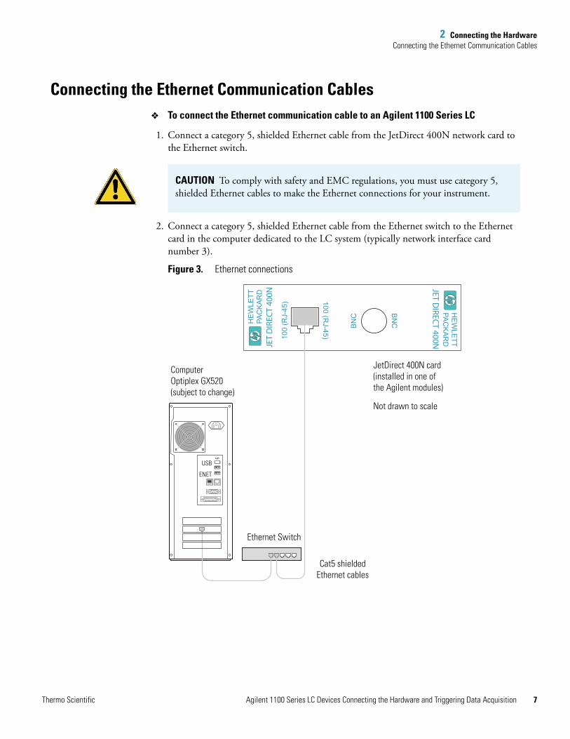
Connecting the Ethernet Communication CablesTo connect the Ethernet communication cable to an Agilent 1100 Series LC
1. Connect a category 5, shielded Ethernet cable from the JetDirect 400N network card to the Ethernet switch.
2. Connect a category 5, shielded Ethernet cable from the Ethernet switch to the Ethernet card in the computer dedicated to the LC system (typically network interface card number 3).
Figure 3. Ethernet connections
CAUTION To comply with safety and EMC regulations, you must use category 5, shielded Ethernet cables to make the Ethernet connections for your instrument.
HE
WLE
TTPA
CK
AR
DJET D
IRECT 400N
BN
C
BN
C
100 (RJ-45)10
0 (R
J-45
)
HE
WLE
TTPA
CK
AR
DJE
T D
IREC
T 40
0N
Not drawn to scale
USB
ENET
Cat5 shieldedEthernet cables
Ethernet Switch
JetDirect 400N card(installed in one of the Agilent modules)
ComputerOptiplex GX520(subject to change)
Thermo Scientific Agilent 1100 Series LC Devices Connecting the Hardware and Triggering Data Acquisition 7
2 Connecting the HardwareInstalling the External Contact Interface Board
8
Installing the External Contact Interface BoardIf your Agilent 1100 Series Autosampler is not already equipped with an external contact interface board, install one as described below.
To install the external contact interface board
1. If you have not already done so, turn off the autosampler and unplug it from line power.
2. To prevent damage to the interface board, ensure that you are using ESD protection. For more information on preventing damage caused by an electric discharge, refer to the Reference Manual for the Agilent module.
3. To remove the cover plate from the slot where you plan to install the external contact interface board, loosen the two screws that fasten the plate to the chassis of the autosampler.
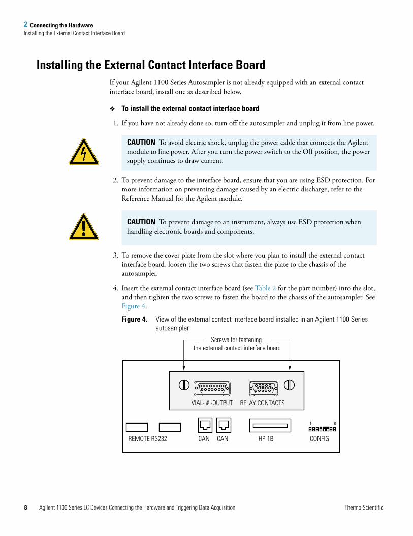
4. Insert the external contact interface board (see Table 2 for the part number) into the slot, and then tighten the two screws to fasten the board to the chassis of the autosampler. See Figure 4.
Figure 4. View of the external contact interface board installed in an Agilent 1100 Series autosampler
CAUTION To avoid electric shock, unplug the power cable that connects the Agilent module to line power. After you turn the power switch to the Off position, the power supply continues to draw current.
CAUTION To prevent damage to an instrument, always use ESD protection when handling electronic boards and components.
1 8
Screws for fastening the external contact interface board
CAN CAN HP-1B CONFIG
RELAY CONTACTS
REMOTE RS232
VIAL- # -OUTPUT
Agilent 1100 Series LC Devices Connecting the Hardware and Triggering Data Acquisition Thermo Scientific
2 Connecting the HardwareConnecting the Trigger Cable
T
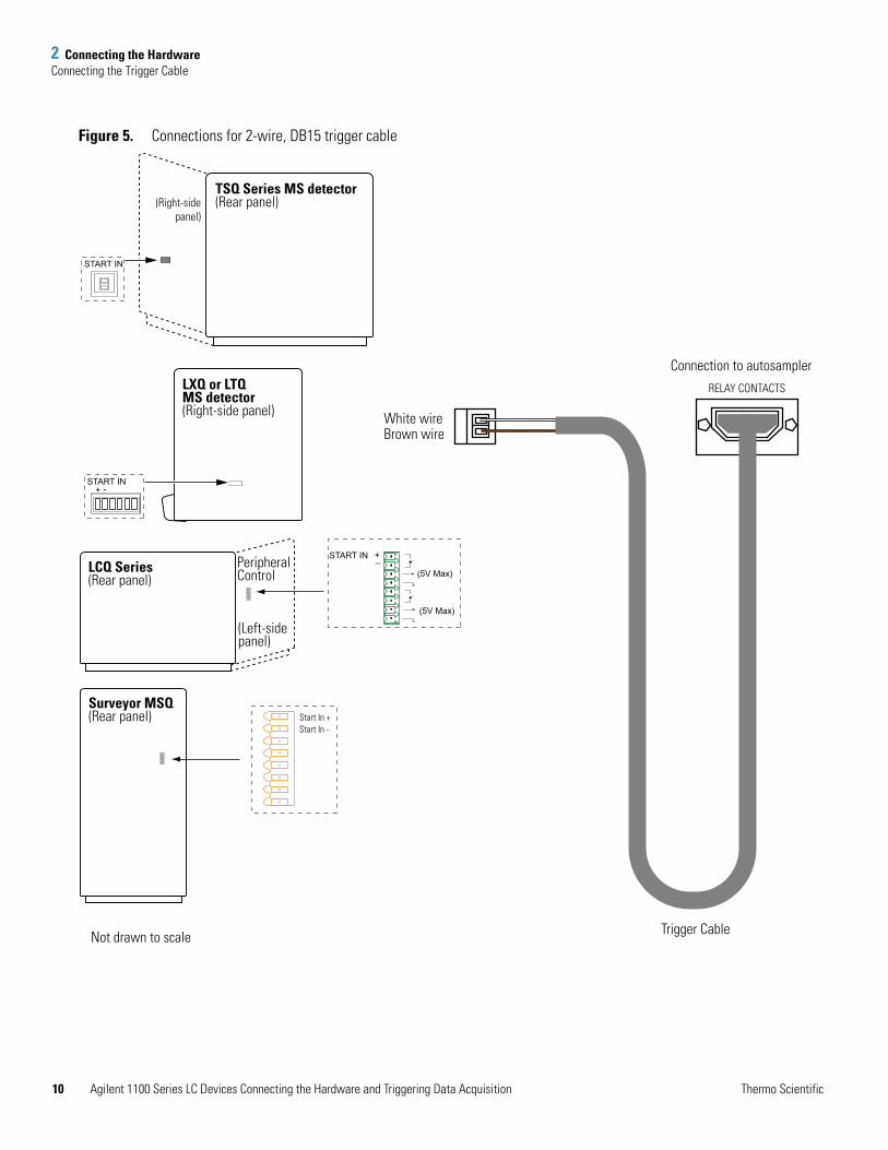
Connecting the Trigger CableA trigger cable with a DB15 connector relays the start signal from the autosampler to the MS detector.
To connect the trigger cable to the Agilent autosampler and the MS detector
1. If you have not already done so, install the external contact interface board as described in “Installing the External Contact Interface Board.”
2. Connect the 2-pin connector to the I/O panel of the MS detector, such that the white wire is connected to the Start In+ pin and the brown wire is connected to the Start In– pin.
3. Connect the DB15 connector to the RELAY CONTACTS receptacle located on the external contact interface board of the Agilent 1100 Series autosampler. See Figure 5.
hermo Scientific Agilent 1100 Series LC Devices Connecting the Hardware and Triggering Data Acquisition 9
2 Connecting the HardwareConnecting the Trigger Cable
10
Figure 5. Connections for 2-wire, DB15 trigger cable
Surveyor MSQ(Rear panel)
+ -
Not drawn to scale
LXQ or LTQMS detector(Right-side panel)
START IN
START IN
TSQ Series MS detector(Rear panel)(Right-side
panel)
LCQ Series(Rear panel)
(Left-sidepanel)
PeripheralControl
RELAY CONTACTS
White wireBrown wire
Trigger Cable
Connection to autosampler
Start In +Start In -
START IN
(5V Max)
(5V Max)
+–
Agilent 1100 Series LC Devices Connecting the Hardware and Triggering Data Acquisition Thermo Scientific
3
Configuring the Autosampler for Contact Closure
The Agilent 1100 Series devices query the PC for the stack IP address only during their start up procedure. Therefore, complete the following procedure, and ensure that the Xcalibur Home Page window is open before you turn on the Agilent 1100 Series devices.
To assign contact closure control to the Agilent 1100 Series autosampler
1. Choose Start > All Programs > Xcalibur > Instrument Configuration.
The Instrument Configuration dialog box appears.
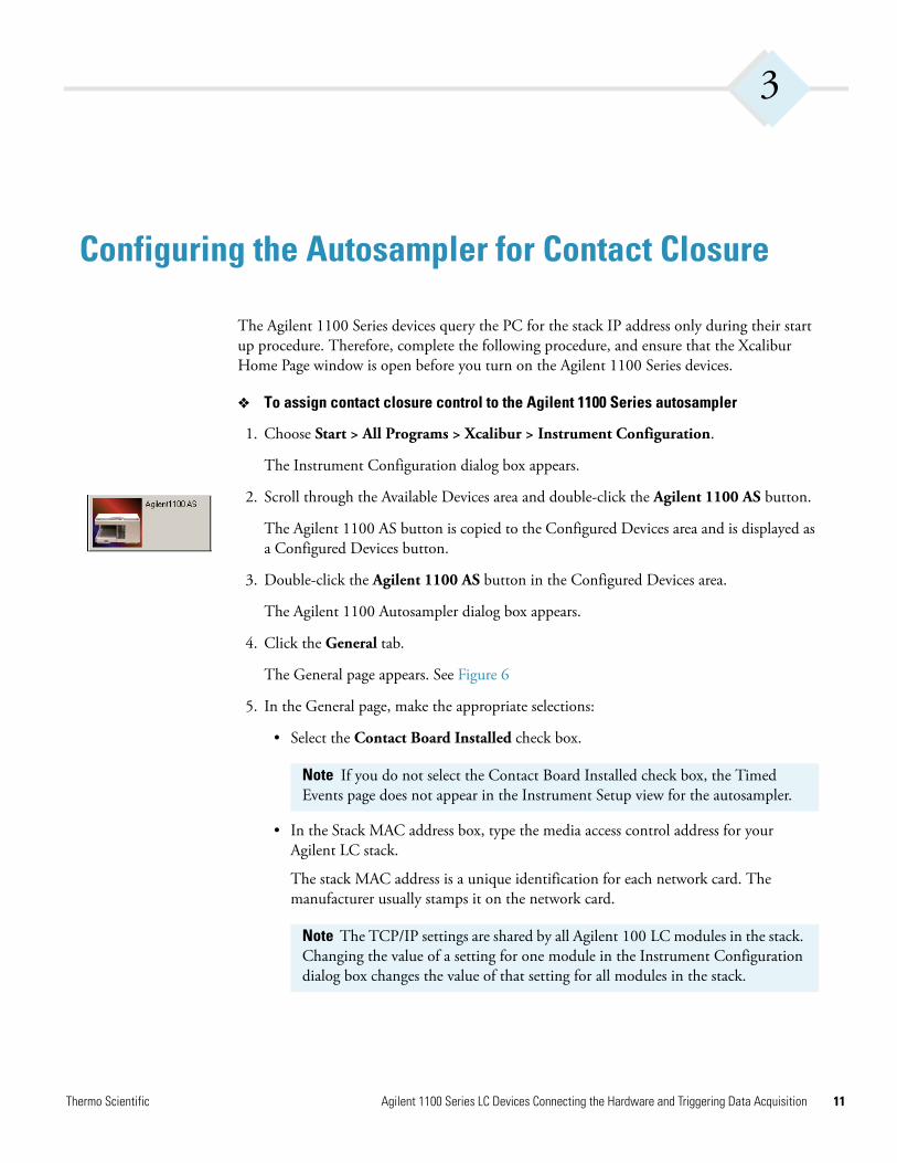
2. Scroll through the Available Devices area and double-click the Agilent 1100 AS button.
The Agilent 1100 AS button is copied to the Configured Devices area and is displayed as a Configured Devices button.
3. Double-click the Agilent 1100 AS button in the Configured Devices area.
The Agilent 1100 Autosampler dialog box appears.
4. Click the General tab.
The General page appears. See Figure 6
5. In the General page, make the appropriate selections:
• Select the Contact Board Installed check box.
• In the Stack MAC address box, type the media access control address for your Agilent LC stack.
The stack MAC address is a unique identification for each network card. The manufacturer usually stamps it on the network card.
Note If you do not select the Contact Board Installed check box, the Timed Events page does not appear in the Instrument Setup view for the autosampler.
Note The TCP/IP settings are shared by all Agilent 100 LC modules in the stack. Changing the value of a setting for one module in the Instrument Configuration dialog box changes the value of that setting for all modules in the stack.
Thermo Scientific Agilent 1100 Series LC Devices Connecting the Hardware and Triggering Data Acquisition 11
3 Configuring the Autosampler for Contact Closure
12
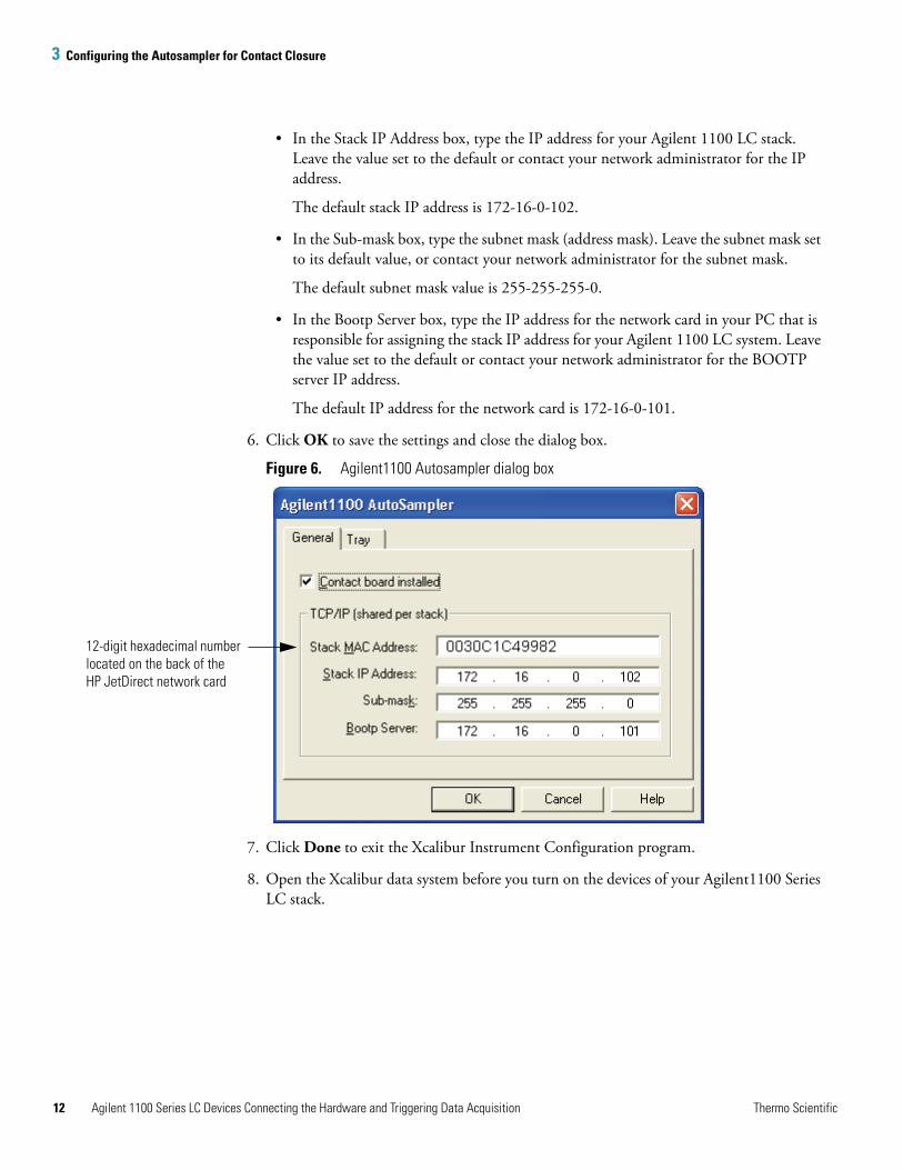
• In the Stack IP Address box, type the IP address for your Agilent 1100 LC stack. Leave the value set to the default or contact your network administrator for the IP address.
The default stack IP address is 172-16-0-102.
• In the Sub-mask box, type the subnet mask (address mask). Leave the subnet mask set to its default value, or contact your network administrator for the subnet mask.
The default subnet mask value is 255-255-255-0.
• In the Bootp Server box, type the IP address for the network card in your PC that is responsible for assigning the stack IP address for your Agilent 1100 LC system. Leave the value set to the default or contact your network administrator for the BOOTP server IP address.
The default IP address for the network card is 172-16-0-101.
6. Click OK to save the settings and close the dialog box.
Figure 6. Agilent1100 Autosampler dialog box
7. Click Done to exit the Xcalibur Instrument Configuration program.
8. Open the Xcalibur data system before you turn on the devices of your Agilent1100 Series LC stack.
12-digit hexadecimal number located on the back of the HP JetDirect network card
Agilent 1100 Series LC Devices Connecting the Hardware and Triggering Data Acquisition Thermo Scientific
4
Triggering Data Acquisition with the Autosampler
If you want the Agilent 1100 series autosampler to trigger data acquisition, you must make the appropriate selections in the Timed Events page for the autosampler for each instrument method you create. Instrument methods contain the contact closure signals, the chromatographic conditions, and the MS detector settings for an LC/MS application.
To trigger data acquisition with the Agilent 1100 Series autosampler
1. Choose Start > All Programs > Xcalibur > Xcalibur.
The Home Page appears.
2. Click the Instrument Setup button.
The Instrument Setup window appears.
3. Click the Agilent 1100 AS button in the Instrument Setup viewbar located on the left side of the window.
The Instrument Setup view for the Agilent 1100 AS appears.
4. Click the Timed Events tab.
The Timed Events page appears.
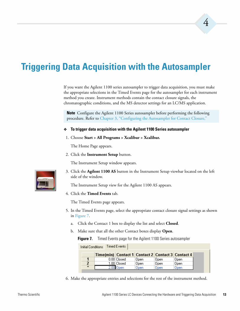
5. In the Timed Events page, select the appropriate contact closure signal settings as shown in Figure 7.
a. Click the Contact 1 box to display the list and select Closed.
b. Make sure that all the other Contact boxes display Open.
Figure 7. Timed Events page for the Agilent 1100 Series autosampler
6. Make the appropriate entries and selections for the rest of the instrument method.
Note Configure the Agilent 1100 Series autosampler before performing the following procedure. Refer to Chapter 3, “Configuring the Autosampler for Contact Closure,”
Thermo Scientific Agilent 1100 Series LC Devices Connecting the Hardware and Triggering Data Acquisition 13

4 Triggering Data Acquisition with the Autosampler
14
7. Save your method with an appropriate name.
8. Choose File > Exit to close the Instrument Setup window. Xcalibur prompts you with the Save As dialog box, the File Summary Information Dialog box, and the File Save - Audit Trail dialog box.
Agilent 1100 Series LC Devices Connecting the Hardware and Triggering Data Acquisition Thermo Scientific
5
Turning Off the Solvent Tracking Feature
The solvent tracking feature on the Agilent 1100 LC pumps is not supported by Xcalibur at this time. You must turn off this feature to prevent error messages from terminating the data acquisition.
To turn off the solvent tracking feature on the Agilent 1100 pump
1. If Xcalibur is open, close it.
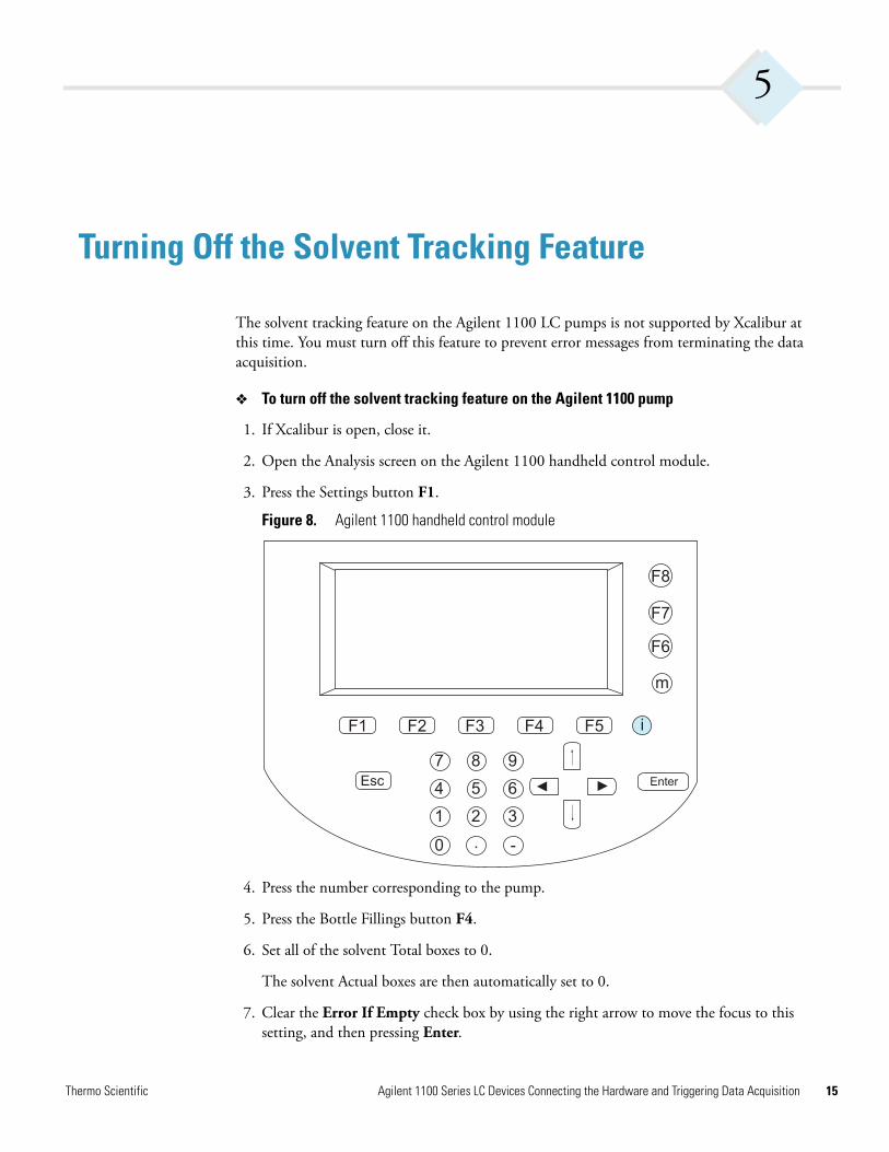
2. Open the Analysis screen on the Agilent 1100 handheld control module.
3. Press the Settings button F1.
Figure 8. Agilent 1100 handheld control module
4. Press the number corresponding to the pump.
5. Press the Bottle Fillings button F4.
6. Set all of the solvent Total boxes to 0.
The solvent Actual boxes are then automatically set to 0.
7. Clear the Error If Empty check box by using the right arrow to move the focus to this setting, and then pressing Enter.
F1
F8
i
m
F7
F6
F2 F3 F4 F5
987
5 64
1 2 3
0 . -
Esc Enter◄
◄
Thermo Scientific Agilent 1100 Series LC Devices Connecting the Hardware and Triggering Data Acquisition 15

5 Turning Off the Solvent Tracking Feature
16
8. Press the Done button F6.
9. From the Windows XP start menu, choose All Programs > Xcalibur > Xcalibur.
The Home Page appears.
The Agilent 1100 devices should reconnect and appropriately display their status.
10. If the Info view is not displayed, choose View > Info View.
Agilent 1100 Series LC Devices Connecting the Hardware and Triggering Data Acquisition Thermo Scientific
A
Upgrading an HP 1100 Series LC
The Xcalibur 2.0 and higher data system supports control of the Hewlett-Packard (HP) 1100 Series LC only if you upgrade the HP 1100 communication interface to an Ethernet interface.
To upgrade your HP 1100 Series LC
1. Order the appropriate upgrade parts from your local office for Thermo Electron San Jose products:
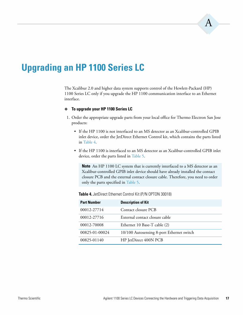
• If the HP 1100 is not interfaced to an MS detector as an Xcalibur-controlled GPIB inlet device, order the JetDirect Ethernet Control kit, which contains the parts listed in Table 4.
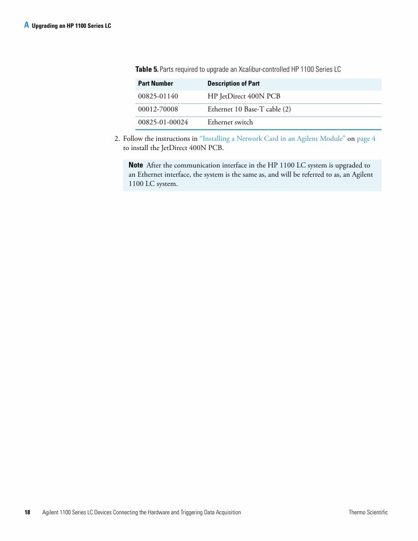
• If the HP 1100 is interfaced to an MS detector as an Xcalibur-controlled GPIB inlet device, order the parts listed in Table 5.
Note An HP 1100 LC system that is currently interfaced to a MS detector as an Xcalibur-controlled GPIB inlet device should have already installed the contact closure PCB and the external contact closure cable. Therefore, you need to order only the parts specified in Table 5.
Table 4. JetDirect Ethernet Control Kit (P/N OPTON 30018)
Part Number Description of Kit
00012-27714 Contact closure PCB
00012-27716 External contact closure cable
00012-70008 Ethernet 10 Base-T cable (2)
00825-01-00024 10/100 Autosensing 8-port Ethernet switch
00825-01140 HP JetDirect 400N PCB
Thermo Scientific Agilent 1100 Series LC Devices Connecting the Hardware and Triggering Data Acquisition 17
A Upgrading an HP 1100 Series LC
18
2. Follow the instructions in “Installing a Network Card in an Agilent Module” on page 4 to install the JetDirect 400N PCB.
Table 5. Parts required to upgrade an Xcalibur-controlled HP 1100 Series LC
Part Number Description of Part
00825-01140 HP JetDirect 400N PCB
00012-70008 Ethernet 10 Base-T cable (2)
00825-01-00024 Ethernet switch
Note After the communication interface in the HP 1100 LC system is upgraded to an Ethernet interface, the system is the same as, and will be referred to as, an Agilent 1100 LC system.
Agilent 1100 Series LC Devices Connecting the Hardware and Triggering Data Acquisition Thermo Scientific
I
Index
AAgilent 1100 Series LC
configuring autosampler for contact closure 11external contact interface PCB, installing 8solvent tracking feature, deactivating 15supported mainboards for JetDirect cards 4
Agilent LAN interface board (G1369A) 5
Cconfiguring the Agilent 1100 Series Autosampler 11contact board 11contact closure, configuring the Agilent Autosampler for 11Contacting vi
Ddata acquisition, triggering 13deactivating the solvent tracking feature for Agilent 1100 LC pumps 15
EElectric shock safety precaution 5, 8ESD precaution vi, 6, 8Ethernet cable connections 7Ethernet card for upgrading HP 1100 LC 17
Ffirmware for Agilent LC 1
HHP 1100 Series LC, upgrading to Ethernet interface 17
Iinstrument methods, triggering data acquisition 13
JJetDirect boards, supported 4
MMAC address 4mainboards supported for JetDirect Cards 4
Ssafety precautions vislot cover, removing from an Agilent module visolvent tracking feature for Agilent pumps 15stack IP address 12stack MAC address 4, 12
XXcalibur data system
Instrument Configuration program, configuring the Agilent 1100 series autosampler for contact closure 11
Instrument Setup view 13
Thermo Scientific Agilent 1100 Series LC Devices Connecting the Hardware and Triggering Data Acquisition 19