Embed Size (px)
Citation preview

s
Agilent 1100 SeriesNano Pump
User Manual
1

ii 1100 Series Nano Pump User Manual
Notices© Agilent Technologies, Inc. 2002
No part of this manual may be reproduced in any form or by any means (including elec-tronic storage and retrieval or translation into a foreign language) without prior agree-ment and written consent from Agilent Technologies, Inc. as governed by United States and international copyright laws.
Manual Part NumberG2226-90000
EditionEdition 07/02
Printed in Germany
Agilent Technologies, Deutschland GmbHHewlett-Packard Strasse 8 76337 Waldbronn
WarrantyThe material contained in this docu-ment is provided “as is,” and is sub-ject to being changed, without notice, in future editions. Further, to the max-imum extent permitted by applicable law, Agilent disclaims all warranties, either express or implied, with regard to this manual and any information contained herein, including but not limited to the implied warranties of merchantability and fitness for a par-ticular purpose. Agilent shall not be liable for errors or for incidental or consequential damages in connec-tion with the furnishing, use, or per-formance of this document or of any information contained herein. Should Agilent and the user have a separate written agreement with warranty terms covering the material in this document that conflict with these terms, the warranty terms in the sep-arate agreement shall control.
Technology Licenses The hardware and/or software described in this document are furnished under a license and may be used or copied only in accor-dance with the terms of such license.
Safety Notices
CAUTION
A CAUTION notice denotes a hazard. It calls attention to an operating pro-cedure, practice, or the like that, if not correctly performed or adhered to, could result in damage to the product or loss of important data. Do not proceed beyond a CAUTION notice until the indicated conditions are fully understood and met.
WARNING
A WARNING notice denotes a haz-ard. It calls attention to an operat-ing procedure, practice, or the like that, if not correctly performed or adhered to, could result in personal injury or death. Do not proceed beyond a WARNING notice until the indicated conditions are fully understood and met.
Warning Symbols Used on the Instrument
The apparatus is marked with this symbol when the user should refer to the instruction manual in order to prevent risk of harm to the operator and to protect the apparatus against damage.
!

In This Manual…
1100 Series Nano Pump User Manua
This manual contains information for using your Nano Pump.
1
Introduction - Around your nano pumpIn this chapter you will find an introduction to the nano pump and some hardware details to identify the parts of the pump and their function.
2
Getting startedIn this chapter you will find road maps to help you to start an analysis with the nano pump. In addition it provides different ChemStation screens necessary to configure and start an analysis with the nano pump.
Follow the step by step priming procedure before using the nano pump in micro mode.
3
Become an expertIn this chapter you will find hints to optimize your nano LC system to achieve best chromatographic results. It also offers diagnosis and build-in tests for maintenance features.
Annex A
Safety Informationl iii

iv
1100 Series Nano Pump User Manual
Contents
1 Introduction - Around your Nano Pump
1100 Series Nano Pump User Manua
Introduction to the nano pump 2
Nano Pump Main Overview 3
Pumphead Overview 4
Flow connections 5
Fittings and ferrules 6
Electrical connections 7
2 Getting started
Road maps to start an analysis with the nano pump 10
Road map to configure the nano pump 10Road map to prepare the nano pump for an analysis 10Road map to start an analysis 11
Using the ChemStation to Configure your Pump 12
Pump configuration screen 12Pump auxiliary screen 13Setup pump parameter screen 15
Priming the pump for best results 20
Manually Priming the Solvent Channels. 20Purging the Pump 21
3 Become an expert
Hints for Successful Use of the Capillaries 26
Hints for Successful Use of the Micro Vacuum Degasser 28
l v
vi
Hints for Successful Use of the Nano Pump 29
Hints for Using the Fast Composition Change/Reconditioning 30
Purpose 30How the Function Works 30
Hints for Successful Use of the Micro Well Plate Sampler 32
Hints for Successful Use of the Column and Switching Valve Compartment 33
Best Practices for Filters 34
The solvent inlet filters 34Inline filter 35
Hints for Successful use of Solvents and Mobile Phase 36
Hints for Choosing the Primary Flow 37
Hints to Optimize the Compressibility Compensation Setting 39
Diagnosis screens 41
Test screens 44
EMF Screen 45
A Safety Information
Safety Information 48
General 48Operation 48Safety Symbols 49
Lithium Batteries Information 51
Danish Information 51
Radio Interference 52
Test and Measurement 52
Sound Emission 53
Manufacturer’s Declaration 53
1100 Series Nano Pump User Manual

1100 Series Nano Pump User Manua
Solvent Information 54
Solvents 54
Agilent Technologies on Internet 55
Index 57
l vii

viii
1100 Series Nano Pump User Manual
Agilent 1100 Series Nano PumpUser Manual
1Introduction - Around your Nano Pump
Introduction to the nano pump 2
Nano Pump Main Overview 3
Pumphead Overview 4
Flow connections 5
Fittings and ferrules 6
Electrical connections 7
In this chapter you will find an introduction to the nano pump and hardware details to identify the parts of the pump and their function.
For more information on how to install a nano pump in direct injection mode, refer to the Service Manual G2226-60100 Chapter 1, Installing the Pump.
For more information on the different stacking possibilities, for a nano pump included in an online sample enrichment LC/Ion trap MS, refer to the Orientation Guide G2228-90000.
1Agilent Technologies

1 Introduction - Around your Nano Pump
Introduction to the nano pump
2
The nano pump consists of two identical pumping units in a single housing. It generates gradients by high-pressure mixing. A solvent selection valve provides flexibility in the choice of solvents.
Mobile phase composition is produced by mixing the outputs of pump A and pump B. The solvent selection valve allows the pump A output to originate from either channel A1 or channel A2. The pump B output may originate from either channel B1 or channel B2.
The primary flow produced by the two pumping units is proportioned in an electromagnetic proportional valve (EMPV). The remaining column flow is measured in a mass flow sensitive flow sensor. The measured flow is compared with the user-entered column flow setpoint. The flow sensor controls the EMPV current, causing the EMPV to correctly proportion the column flow. The primary flow in excess of the required column flow volume is directed to the waste.
Solvent degassing is not done directly in the pump. A 4-channel, low volume micro vacuum degasser, available as a separate module, provides degassed solvents to the pump channel inputs. Solvent degassing is required for best flow stability and detector stability, especially at the low flow rates required to run nano LC applications.
The flow range of the nano pump is between 0.1 µl/min and 1 µl/min.
1100 Series Nano Pump User Manual

Introduction - Around your Nano Pump 1
Nano Pump Main Overview
1100 Series Nano P
1
2
3
4
5
6
7
Figure 1 Nano pump main overview
1 Pumpdrive A 8 Main Board
2 Damper 9 Power Supply
3 EMPV 10 Fan
4 Outlet Ball Valve A 11 Flow Sensor
5 Pumphead A 12 Pumphead B
6 Solvent Selection Valve 13 Active Inlet Valve B
7 Leak Sensor
8
9
10
11
12
13
ump User Manual 3

1 Introduction - Around your Nano Pump
Pumphead Overview
4
1
2
3
4
5
Figure 2 Pumphead overview
Pumphead assembly G1311-60004
1 Outlet ball valve G1312-60012
2 Outlet ball valve to piston 2 capillary G1312-67300
3 Support ring 5001-3739
4 Plunger housing (including springs) G1311-60002
5 Sapphire plunger 5063-6586
6 Screw M5, 60 mm 0515-2118
7 Adapter G1312-23201
8 Screw lock 5042-1303
9 Pump chamber housing G1311-25200
10 Seal (pack of 2)Seal (pack of 2), normal phase applications
5063-65890905-1420
11 Active inlet valve (complete with cartridge)Replacement cartridge for active inlet valve
G1312-600105062-8562
6
7
8
9
11
10
1100 Series Nano Pump User Manual

Introduction - Around your Nano Pump 1
Flow connections
1100 Series Nano P
Figure 3 Flow connections
1 Connection tube A/A G1311-67304
2 Outlet ball valve to piston 2 capillary A/A G1312-67300
3 Mixing capillary A/A G1312-67302
4 Restriction capillary A/A G1312-67304
5 Damper to Filter capillary A/A 250 µm 130 mm 01090-87308
6 Filter to EMPV capillary A/A 170 µm 280 mm G1375-87400
7 EMPV to Flow Sensor capillary D/D 25 µm 220 mm G1375-87321
8 Flow Sensor to Sampler capillary D/C 25 µm 350 mm G1375-87322
9 Flow Sensor to Sampler capillary D/C 25 µm 550 mm G1375-87323
1 1
2 2
3 3
4
5 6 7
8
ump User Manual 5

1 Introduction - Around your Nano Pump
Fittings and ferrules
6
A SwagelockFitting+front and back ferrule 5062-2418 (10/pk)
B Lite TouchFitting
Ferrule and lock ring
5063-6593 (10/pk)
5065-4423 (10/pk)
C Rheodyne PEEK fitting 5065-4410 (6 fit/2 plug)
D Fingertight Double winged nut 5065-4422 (10/pk)
1100 Series Nano Pump User Manual

Introduction - Around your Nano Pump 1
Electrical connections
Figure 4 Electrical connections
1
2
3
4
5
6
7
8
9
1100 Series Nano P
1 Configuration switch
2 GPIB
3 Slot interface board
4 RS232
5 Analog output
6 Remote
7 CAN-bus
8 Power plug
9 Security lever
ump User Manual 7

8
1 Introduction - Around your Nano Pump
1100 Series Nano Pump User Manual

Agilent 1100 Series Nano PumpUser Manual
2Getting started
Road maps to start an analysis with the nano pump 10
Road map to configure the nano pump 10
Road map to prepare the nano pump for an analysis 10
Road map to start an analysis 11
Using the ChemStation to Configure your Pump 12
Pump configuration screen 12
Pump auxiliary screen 13
Setup pump parameter screen 15
Priming the pump for best results 20
Manually Priming the Solvent Channels. 20
Purging the Pump 21
9Agilent Technologies

2 Getting started
Road maps to start an analysis with the nano pump
Road map to configure the nano pump
10
The road map below guides you through all parameters you may need to configure your nano pump.
Setup the Primary Flow
page 13
Setup the Column Flow Ready Condition page 13
Setup theMinimum Strokepage 14
Setup the Solvent Compressibilitypage 14
Setup the Mixer Volume page 12
To configure the nano pump
Setup the Solvent Calibration page 18
Start Here!
Road map to prepare the nano pump for an analysis
The road map below gives you an overview of the necessary steps to prepare the nano pump before starting an analysis.
When the pump is used for the first time or has been turned off for a certain time, it is
NOTErecommended to purge each channel at 2500 µl/min for 1 minute at least.Before running the pump in micro mode, run it in normal mode until the system pressure is stable.
1100 Series Nano Pump User Manual

1100 Series Nano P
Getting started 2
PurgeSet the Purge Time page 22
PurgeSet the Purge Flow Rate page 22
PurgeStart the purge
page 22
2. Normal ModeSet the Normal Mode page 16
1. PurgeSet the Purge Channel page 22
Before starting an analysis with the nano pump
Normal ModeSet the Column Flow page 17
Start Here!
Normal ModeSet the Pressure Limit page 19
Normal ModeSet the Solvent Composition page 18
Road map to start an analysis
The road map below provides an overview of all different parameters you may need to configure when you run an analysis in micro mode.
Set the Column Flow
page 17
Set the Stop Time
page 17
Set the Fast reconditioning ON or OFFpage 17
Set the Solvent Compositionpage 18
Set the Micro Modepage 16
Starting an analysis with the nano pump
Set the Solvent Calibrationpage 18
Start Here!
Set thePressure Limit
page 19
Set the Gradient Timetablepage 18
ump User Manual 11
2 Getting started
Using the ChemStation to Configure your Pump
Pump configuration screen
12
Step 2
Step 1
To get to this screen, select:
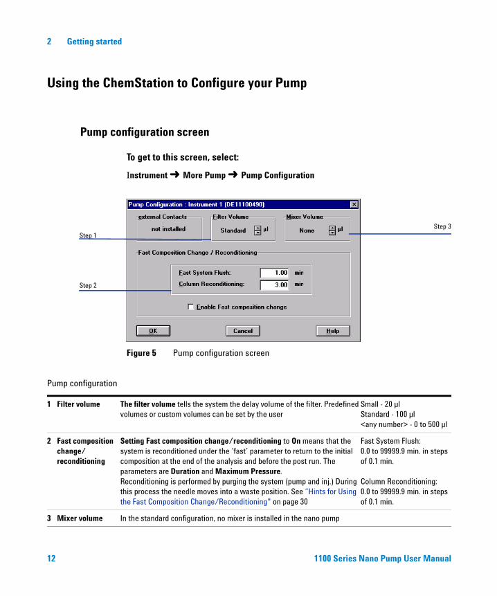
Instrument ➜ More Pump ➜ Pump Configuration
Figure 5 Pump configuration screen
Step 3
Pump configuration
1 Filter volume The filter volume tells the system the delay volume of the filter. Predefined volumes or custom volumes can be set by the user
Small - 20 µlStandard - 100 µl<any number> - 0 to 500 µl
2 Fast composition change/reconditioning
Setting Fast composition change/reconditioning to On means that the system is reconditioned under the ‘fast’ parameter to return to the initial composition at the end of the analysis and before the post run. The parameters are Duration and Maximum Pressure.Reconditioning is performed by purging the system (pump and inj.) During this process the needle moves into a waste position. See “Hints for Using the Fast Composition Change/Reconditioning" on page 30
Fast System Flush: 0.0 to 99999.9 min. in steps of 0.1 min.
Column Reconditioning: 0.0 to 99999.9 min. in steps of 0.1 min.
3 Mixer volume In the standard configuration, no mixer is installed in the nano pump
1100 Series Nano Pump User Manual

Getting started 2
Pump auxiliary screen
1100 Series Nano P
1
2
To get to this screen, select:
Instrument ➜ More Pump ➜ Pump auxiliary
Figure 6 Pump auxiliary screen
3
4
Pump auxiliary
1 Primary Flow The primary flow is the flow before the EMPV.
Depending on the requirements of the analysis it can be set to:• Low solvent consumption mode• Standard mode• Fast gradients modeFor more information see “Hints for Choosing the Primary Flow" on page 37.
Low solvent consumption200 to 500 µl/min.
Default value500 to 800 µl/min.
Fast gradients800 to 1300 µl/min.
2 Column Flow Ready condition
If the column flow cannot reach the desired setpoint, the start of the analysis can be interrupted. You may specify the condition as “%” which determines the percentage range where the pump is allowed to start the analysis, or “Always ready”, which starts the analysis independent of the column flow.
ump User Manual 13

2 Getting started
3 Minimum Stroke The minimum stroke defines the volume of mobile phase displaced by one stroke of piston 1. The stroke volume of the pump influences the mixing performance and gradient linearity. The stroke of each channel is based on the flow rate per channel, not on the total flow. If you select a minimum stroke that is smaller than the one that would be used by the pump operating in AUTO mode, the pump will use the higher stroke volume.
AUTO (default):The pump selects a stroke volume based on the set flow rate.
Between 20 and 100 µl:• 20 µl for best gradient.• 100 µl for a longer seal
lifetime.
4 Compressibility The compressibility of the mobile phase has an effect on the performance of the pump. For best flow accuracy and mixing performance you can set the parameter according to the mobile phase being used.
The default value is 50 × 10-6 for channel A and 115 × 10-6 for channel B. Always set the compressibility value for both channels.
Limits: 0 through 150.
Solvent Compressibility (10-6 per bar).
The compressibility parameter is stored in your method.For more information see “Hints to Optimize the Compressibility Compensation Setting" on page 39
Acetone 126Acetonitrile 115Benzene 95Carbon tetrachloride 110Chloroform 100Cyclohexane 118Ethanol 114Ethyl acetate 104Heptane 120Hexane 150Isobutanol 100Isopropanol (2-Propanol) 100Methanol 1201-Propanol 100Toluene 87Water 46
Pump auxiliary (continued)
14
1100 Series Nano Pump User Manual
Getting started 2
Setup pump parameter screen
1100 Series Nano P
1
2
3
4
To get to this screen, select:
Instrument ➜ Setup pump
Figure 7 Setup pump parameter screen
5
ump User Manual 15

2 Getting started
Setup pump
1 Mode
• Micro Mode
• Normal Mode
The nano pump can be set in 2 modes:• The micro flow mode• The normal flow mode
In micro flow mode, the primary flow produced by the two pumping units is proportioned in the EMPV. The remaining column flow is measured in the flow sensor. The measured flow is compared with the user-entered column flow setpoint. The flow sensor controls the EMPV current, causing the EMPV to correctly proportion the column flow. The primary flow in excess of the required column flow volume is directed to the waste.
In normal mode, the EMPV is completely closed to the waste and the flow sensor measures not the flow. The complete primary flow produced by the two pumping units goes to the column and is not proportioned in the EMPV.
Micro flow modeFrom 0.1 to 1 µl/min.
Normal flow modeFrom 0.00 to 2500 µl/min.
16 1100 Series Nano Pump User Manual

Getting started 2
2 Control • Column Flow
• Stoptime
• Fast reconditioning
• Post Time
The column flow sets the volume of solvent / time which reaches the column.
The stoptime sets a time limit for the analysis. After the stoptime, all gradients are stopped and the pump parameters return to their initial values. The pump can be used as a stoptime master for the complete analytical system.
Setting Fast Reconditioning to On means that the system is reconditioned under the ‘fast’ parameter to return to the initial composition at the end of the analysis. This is performed prior to the post run time. The necessary parameters for the reconditioning are configured using the Pump Configuration dialog box. The parameters are Duration and Maximum Pressure. Reconditioning is performed by purging the system (including the injector) in cooperation with the micro wellplate sampler, which is able to move its needle into a waste position during this process. Fast Reconditioning is supported only in conjunction with the micro wellplate autosampler. For more information see “Hints for Using the Fast Composition Change/Reconditioning" on page 30
The post time sets a not ready state for the pump, to delay the start of the next analysis. You can use Post time to allow your column to equilibrate after changes in solvent composition (for example after gradient elution).
Recommended column flow:Micro flow modeFrom 0.1 to 1 µl/min.
Normal flow modeFrom 0.00 to 2500 µl/min.
Stop time limits:0.0 to 99999 min.No Limit (infinite run time).
Post time limits:0.0 to 99999 min.OFF (0.0 min.).
Setup pump (continued)
1100 Series Nano Pump User Manual 17

2 Getting started
3 Solvents• Solvent composition
• Solvent calibration
For each channel, you may select which of the two solvents to deliver. You can set the percentage of Solvent B to any value from 0 through 100%. Solvent A always delivers the remaining volume, calculated as 100% - %B. The Solvent B scrollbar allows you to turn Solvent B ON or OFF. The text boxes allow you to type a brief description for each of the solvents.If you turn a solvent channel OFF, it will not be used in the timetable.
If Micro Flow mode is selected, you may select a calibration curve out of a set of predefined calibration tables that correct the calibration for the composition of most standard solvent combinations.
4 Timetable You can use the Timetable to program changes in the Pump parameters during the analysis by entering a time in the Time field and appropriate values in the following fields of the timetable. The values in the Pump timetable change linearly with respect to time from the initial value to the value at the time defined in the timetable
Select the Insert button to insert a line above the currently-selected line.Select the Append button to add a line to the end of the table.Select the Cut button to delete the currently-selected line and place it on the clipboard.Select the Copy button to copy the currently selected line to the clipboard.Select the Paste button to paste the line on the clipboard at the current position.Select the Display combination box and select Flow/Press or Solvents to display graphical representations of the flow rate/pressure limit or solvent compositions, or Timetable to display the table for editing. In the graphics mode, select Legend to display the graph titles.
Parameters which can be changed:
TimeTime at which the change occurs.
%B Solvent composition (0 to 100%). The residual percentage is solvent A.
FlowSolvent flow rate.
Max. PressureSystem max pressure limit.
Setup pump (continued)
18 1100 Series Nano Pump User Manual

Getting started 2
5 Pressure limits Sets the maximum and minimum pressure limits for the pump.
Max is the maximum pressure limit at which the pump will switch itself off, protecting the analytical system against over-pressure.
Min is the minimum limit at which the pump will switch itself off, for example, if any solvent reservoir is empty, this prevents system damage through pumping air.
NOTE: The minimum pressure limit becomes active only when the actual pressure rises above the limit. For the system to create an error, the limits must be exceeded for a few seconds.
The maximum pressure limit for the nano pump is 400 bar.
The minimum pressure limit for the nano pump can be any value from 0 through (P-1) bar, where P is the maximum pressure setting.
Setup pump (continued)
1100 Series Nano P
ump User Manual 19
2 Getting started
Priming the pump for best results
20
When you are using the pump for the first time after installation, best results are obtained by performing the following steps:
1 Manually priming the solvent channels.
2 Purging the pump.
Manually Priming the Solvent Channels.
WARNING When opening capillary or tube fittings, solvents may leak. Please observe appropriate safety precautions (such as eye protection, safety gloves, protective clothing) as described in the material handling information and safety data sheet supplied by the solvent vendor, especially when hazardous solvents are used.
NOTE This procedure should be done before the modules are turned on.
1 The degasser accessory kit contains a 20ml plastic syringe and a solvent tube adapter for this syringe. Push the adapter onto the syringe.
2 Pour the intended analytical solvents into the solvent bottles, and install the bottles on the desired solvent channels. Install Isopropanol on channels which will not be used right away.
3 Put a paper towel over the leak sensor in the pump leak tray.
4 Disconnect the channel A solvent tube from the A1 port of the pump solvent selection valve.
WARNING Liquid may drip from the disconnected solvent tube. Make sure to follow appropriate safety precautions.
1100 Series Nano Pump User Manual

1100 Series Nano P
Getting started 2
5 Connect the end of the solvent tube to the syringe adapter. Slowly draw a syringe volume (20 ml) from the solvent tube.
6 Disconnect the solvent tube from the syringe adapter, and reconnect the tube to the A1 port of the solvent selection valve. Eject the syringe contents into an appropriate waste container.
7 Repeat steps 4 to 6 for the three remaining solvent channels.
8 When all 4 solvent channels are manually primed, remove the paper towel from the pump leak tray. Make sure that the pump leak sensor is dry before turning on the pump.
Purging the Pump
1 Make sure that the 1/8 inch plastic waste tube is tightly connected to the barbed waste fitting of the pump EMPV, and routed to an appropriate waste container.
2 Turn on the LC System. All system parameters should be set to default. The degasser should also be turned on at this time.
3 Initialize the system. Then, access the pump controls and make sure the pump mode is set to Normal.
4 Access the pump Purge control. Set up a purge table which will purge all channels for 5 minutes each, at a flow of 2500 µl/min. Then, start the purge.
When the pump has been turned off for
NOTE When the pump has been turned off for a certain time (for example, overnight), oxygen will re-diffuse into the channels between the degasser and the pump. It is suggested to purge each channel at 2500 µl/min for 1 minute at the beginning of each day.
ump User Manual 21

22
2 Getting started
1
2
The Pump Purge mode is used to wash out any kind of contamination, including air bubbles from any or all channels. In this mode, the EMPV is completely open to the waste. The degasser, the pump heads, and the damper are in the flush flowpath.
Figure 8 Purge pump screen
4
3
Purge pump
1 Channel Select the channels to be purged by selecting the appropriate check box.
The channels are purged in sequence.After each channel has been separately purged, you can also select to purge the complete pump system for a specified time with the solvent composition set by the current method.
2 Start Purge Starts the defined purge sequence.
3 Flow Rate Defines the flow rate for the purge in µl/min. Flow rate:from 0.0 to 2500 µl/min
4 Purge Time Defines the purge time in minutes
1100 Series Nano Pump User Manual

1100 Series Nano P
Getting started 2
Table 1 Choice of Priming Solvents for Different Purposes
Activity Solvent Comments
After an installation Isopropanol Best solvent to flush air out of the system
After an installation (second choice)
Ethanol or Methanol Alternative to Isopropanol if no Isopropanol is available
When switching between reverse phase and normal phase (both times)
Isopropanol Best solvent to flush air out of the system
To clean the system when using buffers
Bidistilled water Best solvent to re-dissolve salts
After a solvent change Bidistilled water Best solvent to re-dissolve salts
To clean the capillaries Acetone Best solvent to remove impurities from the capillaries
ump User Manual 23

24
2 Getting started
1100 Series Nano Pump User Manual

Agilent 1100 Series Nano PumpUser Manual
3Become an expert
Hints for Successful Use of the Capillaries 26
Hints for Successful Use of the Micro Vacuum Degasser 28
Hints for Successful Use of the Nano Pump 29
Hints for Successful Use of the Micro Well Plate Sampler 32
Hints for Using the Fast Composition Change/Reconditioning 30
Hints to Optimize the Compressibility Compensation Setting 39
Best Practices for Filters 34
Hints to Optimize the Compressibility Compensation Setting 39
Diagnosis screens 41
Test screens 44
This chapter helps you to optimize your nano LC system to achieve best chromatographic results and describes the diagnosis and build-in tests for maintenance features.
25Agilent Technologies

3 Become an expert
Hints for Successful Use of the Capillaries
26
• When connecting the capillary to a fitting or the column push the capillary into the fitting firmly and smoothly to avoid gaps. Incorrect setting will result in sample dispersion which can cause peak dispersion and reduce the chromatographic fidelity.
• When configuring and installing FS tubing, be careful to avoid shutting doors or inserting cover panels onto the interconnecting FS tubing. Should a door or panel cause a kink or sharp bend in the tubing, set the pump to zero, remove the tubing at once and replace to avoid distributing silica particles through-out the flow circuit.
• When installing for the first time, or tubing replacement, clean both fitting and fused silica tube with isopropanol or acetone in small amount to remove particles before connecting to fittings.
• Tighten fittings until snug, but not overtight so as to cause the fused silica capillaries to be crushed. When bending the fused silica tubing, do not bend or coil into a diameter smaller than 40 mm, to avoid breaking the tubing.
• Should fused silica tubing/fitting be suspected of leaking, set column flow to zero, loosen the fitting, reinsert the fused silica tube and retighten the fitting. Tighten the fitting without re-seating the fused silica tube may allow a gap to remain between the fused silica and the fitting, resulting in peak dispersion and poor chromatographic fidelity. Avoid over-tighten of fittings to avoid crushing the fused silica tubing.
• Inspect fused silica capillaries under a microscope. If at the surface it looks milky, the capillary must be replaced. Crushed fused silica tubing will distribute small particles throughout the down stream flow path and require complete flushing of all fittings and valves from the point of the damaged tube.
40 mm
1100 Series Nano Pump User Manual

1100 Series Nano P
Become an expert 3
• Blocked capillaries will result from the small particles moving downstream. Partly blocked capillaries can be unblocked by removing and reversing the tube, and pumping on the new inlet. Most blocking will take place at the high pressure side of the fused silica tubing and not within the tubing. Reversing the tubing and pumping liquid through the tube before reconnecting into the flow circuit, will remove the particles and clear the tube.
• Avoid the use of alkaline solutions (pH > 8.5) which can attack the fused silica from the capillaries.
• Partially blocked capillaries may generate flow oscillations when the sampler is in mainpass mode and the sample is injected directly onto the analytical column. These oscillations are not observed when the trapping mode configuration is used.
ump User Manual 27
3 Become an expert
Hints for Successful Use of the Micro Vacuum Degasser
28
If you are using the vacuum degasser for the first time, if the vacuum degasser was switched off for any length of time (for example, overnight), or if the vacuum degasser lines are empty, you should prime the vacuum degasser before running an analysis.
The vacuum degasser can be primed by pumping solvent with the nano pump at high flow rate (2.5 ml/min). Priming the degasser is recommended, when:
• vacuum degasser is used for the first time, or vacuum chambers are empty.
• changing to solvent that are immiscible with the solvent currently in the vacuum chambers.
• nano pump was turned OFF for a length of time (for example during night) and volatile solvent mixtures are used.
For more information see the Reference Manual for the Agilent 1100 series micro vacuum degasser.
1100 Series Nano Pump User Manual

Become an expert 3
Hints for Successful Use of the Nano Pump
1100 Series Nano P
• Flush the pump extensively in the purge mode. It is recommended to do this for 4 min each, first with 100% A and then 100% B. Small residual bubbles are removed by pumping in micro mode with the column installed.
• Place the aqueous solvent on channel A and the organic solvent on channel B. The default compressibility and solvent flow sensor calibration settings are set accordingly. Always use the correct calibration values.
• Place solvent cabinet with the solvent bottles always on top (or at a higher level) of the nano pump.
• The system pressure must be higher than 20 Bar at the pump outlet to achieve stable flow rates.
• In micro mode abnormally high column flow variations are an indication of small particles within the system, partially blocked filters or capillaries.
• Prevent blocking of solvent inlet filters (never use the pump without solvent inlet filter). Growth of algae must be avoided, either by using acidic (pH=3) media and/or changing solvent every day.
ump User Manual 29

3 Become an expert
Hints for Using the Fast Composition Change/Reconditioning
30
Fast composition/reconditioning function can not be used for nanospray with MS. If the
Purpose
NOTEflow stops and the needle is not removed from the near-by heated electrode, the needle will plug. Fast composition can not be used between runs because it eliminates the liquid flow to the nanospray tip, which will get plugged or damaged by the counter electrode plate.
The nano pump and the micro well plate sampler are recommended for nano LC applications. Nano LC methods have very low column flow rates, typically around 300 nl/min. At such low flow rates, re-equilibrating the column with a new composition in direct injection mode takes a long time. Therefore it is useful in method development when the autosampler is in mainpass and a new composition is set, to use the fast composition mode and flush the micro well plate sampler loop at high flow rates. The new composition will reach the column much faster.
The Fast Composition Change/Reconditioning function is available only in a system that includes both a nano pump and a micro well plate sampler. This function can be set up to occur automatically between runs, and/or to occur automatically after any manual composition change. Primary Flow is a parameter which exists only when the nano pump is used in the Micro mode. Primary flow is defined as the flow volume and composition available at the inlet to the EMPV. Using this available primary flow, the EMPV and flow sensor work together to deliver and control the requested column flow. All primary flow in excess of the column flow is delivered to waste via the 1/8 inch plastic waste tube connected to the EMPV barbed waste fitting.
The Fast Composition Change/Reconditioning function is available only when the nano
How the Function Works
NOTEpump is operated in the micro mode.
Regardless of when it occurs, the Fast Composition Change/ Reconditioning function is always a 2-step process:
1100 Series Nano Pump User Manual

1100 Series Nano P
Become an expert 3
1 The micro well plate sampler needle is placed over the waste position of the flushport. The pump delivers a high flow rate at the new composition (fast composition change) / at the initial composition (reconditioning) defined in the current method. This flow is maintained for the Fast System Flush time defined in the user interface. During this time, the system is being re-equilibrated, up to the sampler needle outlet.
The high flow rate used for Fast System Flush is not user-defined. For the Fast System
NOTEFlush, the pump operates in pressure control mode at a predefined pressure.The flow rate used for Fast System Flush is the highest flow which can be delivered at the predefined pressure.
2 When the Fast System Flush time has elapsed, the micro well plate sampler needle is returned to the needle-seat. The pump returns to the normal operating mode, reconditioning the column at the flow and initial composition defined in the current method. The column is reconditioned for the Column Reconditioning time defined in the user interface.
In a sequence, the next injection will begin when Fast Composition Change/Reconditioning is completed.
ump User Manual 31

3 Become an expert
Hints for Successful Use of the Micro Well Plate Sampler
32
• For direct injection without trapping columns the valve to bypass function must be used after the sample is transferred to the column. This function results in smaller delay times and sharper gradient curves. The starting time of the gradient should be coincident with the valve to bypass switch time for correct sample transfer.
• For Direct Injection Mode using one column and one pump, set the Micro Well Plate Sampler to use a programmed injection mode and a needle wash. Using both features, the injected sample reaches the analytical column in the shortest time and minimizes sample carry-over from the needle.
• Pressure drop with injector valve in bypass (e.g. during drawing sample) should be comparable to mainpass mode, otherwise the seat or the capillary might be blocked.
1100 Series Nano Pump User Manual

Become an expert 3
Hints for Successful Use of the Column and Switching Valve Compartment
1100 Series Nano P
• When using the Direct Injection Mode, i.e. one column and one pump, the column compartment which also contains the six port micro switching valve, is un-used. The nano LC column (analytical column) is housed within the Nanospray ion source chamber via the Nanospray needle holder.
• When two dimensional (2-D Mode) chromatographic separations are required, the column compartment is used to house either or both the trapping column and the ion exchange columns. The column compartment also houses the 6-port micro switching valve necessary to switch and control the direction of flow of the mobile phases during multi-dimensional separations using two pumps and either two or three columns.
ump User Manual 33

3 Become an expert
Best Practices for Filters
34
Contaminated solvents or algae growth in the solvent bottle will reduce the lifetime of the solvent filter and will influence the performance of the nano pump. This is especially true for aqueous solvents, especially phosphate buffers (pH 4 to 7). The following suggestions will prolong lifetime of the solvent filter and will maintain the performance of the nano pump.
• Use sterile, if possible amber, solvent bottles to slow down algae growth.
• Filter solvents through filters or membranes that remove algae.
• Exchange solvents every two days or refilter.
• If the application permits add 0.1 to 1 milli-Molar sodium acid to the solvent.
• Place a layer of argon on top of your solvent.
• Avoid exposure of the solvent bottles to direct sunlight.
The solvent inlet filtersR
WARNING When opening capillary or tube fittings solvents may leak out. Please observe appropriate safety procedures (for example, goggles, safety gloves and protective clothing) as described in the material handling and safety data sheet supplied by the solvent vendor, especially when toxic or hazardous solvents are used.
The solvent filters are located on the low-pressure side of the nano pump. A blocked filter therefore does not affect the pressure readings of the nano pump. The pressure readings cannot be used to check whether the filter is blocked or not. If the solvent cabinet is placed on top of the nano pump, the filter condition can be checked in the following way:
Remove the solvent inlet tube from the inlet port of the solvent selection valve or the adapter at the active inlet valve. If the filter is in good condition the solvent will freely drip out of the solvent tube (due to hydrostatic pressure). If the solvent filter is partly blocked only very little solvent will drip out of the solvent tube.
1100 Series Nano Pump User Manual
1100 Series Nano P
Become an expert 3
Cleaning the Solvent Filters
• Remove the blocked solvent filter from the bottle-head assembly and place it in a beaker with concentrated nitric acid (65%) for one hour.
• Thoroughly flush the filter with bidistilled water (remove all nitric acid, some columns can be damaged by nitric acid).
• Replace the filter.
Inline filter
CAUTION Never use the system without solvent filters. This could cause damage to the pump valves
The nano pump is equipped with a filter in front of the EMPV.
The standard filter has a volume of typically 100 µl. If the application needs a reduced volume (e.g. for fast gradient) the 20 µl low volume filter (01090-68703) is recommended. Be aware that the filter efficiency and capacity is significantly reduced compared to the standard one.
NOTE Never run the nano pump without an inline filter.
The Nano LC/MS does not require a mixer, since baseline ripples as known from UV detection are not issue for the MS.
ump User Manual 35

3 Become an expert
Hints for Successful use of Solvents and Mobile Phase
36
Always filter solvents through 0.4 µm filters, small particles can permanently block the capillaries, the valves and damage or cause corrosion of parts.
• Avoid the use of alkaline solutions (pH > 8.5) which can attack the fused silica from the capillaries.
• Avoid exposure of the solvent bottles to direct sunlight.
• Avoid the use of the following steel-corrosive solvents:
• Solutions of alkali halides and their respective acids (for example, lithium iodide, potassium chloride, and so on).
• High concentrations of inorganic acids like sulfuric and nitric acid, especially at higher temperatures (replace, if your chromatography method allows, by phosphoric acid or phosphate buffer which are less corrosive against stainless steel).
• Halogenated solvents or mixtures which form radicals and/or acids, for example:
• 2CHCl3 + O2 & 2COCl2 + 2HCl
• This reaction, in which stainless steel probably acts as a catalyst, occurs quickly with dried chloroform if the drying process removes the stabilizing alcohol.
• Chromatographic grade ethers, which can contain peroxides (for example, THF, dioxane, di-isopropylether) such ethers should be filtered through dry aluminium oxide which adsorbs the peroxides.
• Solvents containing strong complexing agents (e.g. EDTA).
• Mixtures of carbon tetrachloride and 2-propanol dissolve stainless steel.
• Mixture of THF and 2-Propanol, can dissolve stainless steel.
• Mobile phase for Nanoflow and proteomics, as a starting point should consist of a mobile phase A,B and a needle wash solvent. The composition would be as follows:
• A = 0.1% Formic acid
• B = 0.1% Formic acid
• Needle wash = 15% Methanol, 84.9 %Water, 0.1 % Formic acid.
1100 Series Nano Pump User Manual

Become an expert 3
Hints for Choosing the Primary Flow
1100 Series Nano P
• Primary Flow is a parameter which exists only when the nano pump is used in the Micro mode. Primary flow is defined as the flow volume and composition available at the inlet to the EMPV. Using this available primary flow, the EMPV and flow sensor work together to deliver and control the requested column flow. All primary flow in excess of the column flow is delivered to waste via the 1/8 inch plastic waste tube connected to the EMPV barbed waste fitting.
NOTE In all cases, primary flow is much higher than column flow. This must be considered when calculating the amount of solvent needed for unattended operation
The user cannot request a specific primary flow value. However, one of three available primary flow ranges can be selected by the user:
Default range (500-800 µl/min)
The default range is the best compromise between performance and solvent savings.
Low Solvent Consumption range (200-500 µl/min)
Since we use very shallow gradients and the time for analysis is usually greater than 10 minutes, we will choose the low solvent consumption mode for the Nanoflow, nanospray configuration.
Fast Gradients range (800-1300 µl/min)
In this range, the pump gradient delay time is as short as possible. This range is specifically recommended for fast-gradient analyses (<3 min.). Solvent consumption is highest in this range.
Table 2 on page 38 gives approximate primary flow values (in µl/min) as a function of selected primary flow range vs. system pressure:
ump User Manual 37

38
3 Become an expert
Actual primary flow values may vary from system to system. If the standard configuration is changed, the primary flow may be higher than the values given in Table 2.
Table 2 Primary flow overview for standard pump configuration
0 barSystem pressure
100 barSystem pressure
200 barSystem pressure
300 barSystem pressure
400 barSystem pressure
Low consumption range
200 225 250 275 300
Default range 500 570 640 710 780
Fast gradient range 800 995 1190 385 1580
1100 Series Nano Pump User Manual

Become an expert 3
Hints to Optimize the Compressibility Compensation Setting
1100 Series Nano P
The compressibility compensation default settings are 50 × 10-6 /bar (best for most aqueous solutions) for pump head A and 115 × 10-6 /bar (to suit organic solvents) for pump head B. The settings represent average values for aqueous solvents (A side) and organic solvents (B side). Therefore it is always recommended to use the aqueous solvent on the A side of the pump and the organic solvent on the B side. Under normal conditions the default settings reduce the pressure pulsation to values (below 1 % of system pressure) that will be sufficient for most applications. If the compressibility values for the solvents used differ from the default settings, it is recommended to change the compressibility values accordingly. Compressibility settings can be optimized by using the values for various solvents described in Table 3 on page 40. If the solvent in use is not listed in the compressibility table, when using premixed solvents and if the default settings are not sufficient for your application the following procedure can be used to optimize the compressibility settings:
Use the nano pump in the Normal Mode at least at 100 µl/min.
NOTE1 Start channel A of the nano pump with the adequate flow rate. The system pressure must be between 50 and 250 bar
2 Before starting the optimization procedure, the flow must be stable. Use degassed solvent only. Check the tightness of the system with the pressure test.
3 Your pump must be connected to a ChemStation or handheld controller, the pressure and%-ripple can be monitored with one of these instruments,otherwise connect a signal cable between the pressure output of the pump and a recording device (for example, 339X integrator) and set parameters.
Zero 50 % Att 23
Chart Speed 10 cm/min
4 Start the recording device with the plot mode.
5 Starting with a compressibility setting of 10 × 10-6 /bar increase the value in steps of 10. Re-zero the integrator as required. The compressibility compensation setting that generates the smallest pressure ripple is the optimum value for your solvent composition.
ump User Manual 39

40
3 Become an expert
6 Repeat step 1 through step 5 for the B channel of your nano pump.
Optimize your compressibility settings by using the values for various solvents listed in the following table:
.
Table 3 Solvent Compressibility
Solvent (pure) Compressibility (10-6/bar)
Acetone 126
Acetonitrile 115
Benzene 95
Carbon tetrachloride 110
Chloroform 100
Cyclohexane 118
Ethanol 114
Ethyl acetate 104
Heptane 120
Hexane 150
Isobutanol 100
Isopropanol 100
Methanol 120
1-Propanol 100
Toluene 87
THF 95
Water 46
1100 Series Nano Pump User Manual

Become an expert 3
Diagnosis screens
1100 Series Nano P
To get to this screen, select:
Diagnosis ➜ ➜ right mouse-click:
Figure 9 Diagnosis system screen
Diagnosis system screen
1 Nano pump - general information General information relative to the pump
• Product Number• Pump Firmware Revision• Manufacturing Date• Serial Number• Pump On Time
1
ump User Manual 41

42
3 Become an expert
1
2
3
4
5
To get to this screen, select:
Diagnosis ➜ ➜ right mouse-click:
Figure 10 Diagnosis pump screen
6
7
8
9
1100 Series Nano Pump User Manual

1100 Series Nano P
Become an expert 3
Diagnosis pump screen
The diagram represents the flow path in the pump. By clicking on the different location a box with following commands appears:
• Update variable display• Switch to top level• Show module tests
On the left side are the parts for pumphead A. On the right side are the parts for pumphead B.
1 Damper • System pressure• Pressure ripple• Pressure plot
2 Outlet ball valve • Outlet ball valve cycles (A)• Outlet ball valve reset log (A)
3 Piston • Liquimeter (A)• Seal wear (A)
4 Active inlet valve • Active inlet valve cycles (A)
5 Solvent selection valve • Solvent selection valve cycles
6 Logbook • Error logbook• Run logbook• Maintenance logbook• Date changes logbook
7 Book • Setup pump• Control• Auxiliary• Data curves• Configuration• Purge
8 Thermometer • Pump mainboard temperature history
9 Identify • LED blink on the module
ump User Manual 43

3 Become an expert
Test screens
44
1
To get to this screen, select:
Diagnosis ➜ Diagnosis ➜ Test
Figure 11 Pump test selection
Pump test selection
1 Available tests The different test give the possibility to check the pump for good working
For more information about these tests see the Service Manual G2226-90100 Chapter 3, Troubleshooting and Test Functions.
• Micro mode pressure test• Normal mode pressure test• Leak test• Nano pump EMPV test• Nano pump flow sensor accuracy
calibration
1100 Series Nano Pump User Manual

Become an expert 3
EMF Screen
1100 Series Nano P
To get to this screen, select:
Diagnosis ➜ ➜
Figure 12 EMF screen
EMF screen
1 EMF info pad The Early Maintenance Feedback Information Pad contains the list of the limits and actual values of the parameters used to assess the current state of maintenance of the system.
You can set a limit for the parameter by entering the value in the edit field.
A value is reset when an entry for the associated part is made in the Maintenance Logbook.
Parameters:
• Seal wear (A)• Liquimeter (A)• Seal wear (B)• Liquimeter (B)
ump User Manual 45

46
3 Become an expert
1100 Series Nano Pump User Manual

Agilent 1100 Series Nano PumpUser Manual
ASafety Information
Safety Information 48
Lithium Batteries Information 51
Danish Information 51
Radio Interference 52
Sound Emission 53
Solvent Information 54
Agilent Technologies on Internet 55
The following general safety precautions must be observed during all phases of operation, service, and repair of this instrument. Failure to comply with these precautions or with specific warnings elsewhere in this manual violates safety standards of design, manufacture, and intended use of the instrument. Agilent Technologies assumes no liability for the customer’s failure to comply with these requirements.
47Agilent Technologies

A Safety Information
Safety Information
48
The following general safety precautions must be observed during all phases of operation, service, and repair of this instrument. Failure to comply with these precautions or with specific warnings elsewhere in this manual violates safety standards of design, manufacture, and intended use of the instrument. Agilent Technologies assumes no liability for the customer’s failure to comply with these requirements.
General
This is a Safety Class I instrument (provided with terminal for protective earthing) and has been manufactured and tested according to international safety standards.
This instrument is designed as a laboratory equipment. Use it in an analytical
Operation
WARNINGenvironment only.
Use this instrument in a manner described in this manual.
Before applying power, comply with the installation section. Additionally the following must be observed.
Do not remove instrument covers when operating. Before the instrument is switched on, all protective earth terminals, extension cords, auto-transformers, and devices connected to it must be connected to a protective earth via a ground socket. Any interruption of the protective earth grounding will cause a potential shock hazard that could result in serious personal injury. Whenever it is likely that the protection has been impaired, the instrument must be made inoperative and be secured against any intended operation.
Make sure that only fuses with the required rated current and of the specified type (normal blow, time delay, and so on) are used for replacement. The use of repaired fuses and the short-circuiting of fuseholders must be avoided.
Any adjustment, maintenance, and repair of the opened instrument under voltage is
WARNINGforbidden.1100 Series Nano Pump User Manual

1100 Series Nano P
Safety Information A
Disconnect the instrument from the line and unplug the power cord before
WARNINGmaintenance.Do not operate the instrument in the presence of flammable gases or fumes. Operation of any electrical instrument in such an environment constitutes a definite safety hazard.
Do not install substitute parts or make any unauthorized modification to the instrument.
Capacitors inside the instrument may still be charged, even though the instrument has been disconnected from its source of supply. Dangerous voltages, capable of causing serious personal injury, are present in this instrument. Use extreme caution when handling, testing and adjusting.
Safety Symbols
Table 4 shows safety symbols used on the instrument and in the manuals.
Table 4 Safety Symbols
Symbol Description
The apparatus is marked with this symbol when the user should refer to the instruction manual in order to prevent risk of harm to the operator and to protect the apparatus against damage.
Indicates dangerous voltages.
Indicates a protected conductor terminal.
Eye damage may result from directly viewing the light produced by the Xenon flash lamp used in this product. Always turn the xenon flash lamp off before removing it.
�
ump User Manual 49

50
A Safety Information
A WARNING notice denotes a hazard. It calls attention to an operating procedure,
WARNINGpractice, or the like that, if not correctly performed or adhered to, could result in personal injury or death.Do not proceed beyond a WARNING notice until the indicated conditions are fully understood and met.
A CAUTION notice denotes a hazard. It calls attention to an operating procedure,
CAUTIONpractice, or the like that, if not correctly performed or adhered to, could result in damage to the product or loss of important data.Do not proceed beyond a CAUTION notice until the indicated conditions are fully understood and met.
1100 Series Nano Pump User Manual

Safety Information A
Lithium Batteries Information
1100 Series Nano P
Danger of explosion if battery is incorrectly replaced. Replace only with the same or
Danish Information
WARNINGequivalent type recommended by the equipment manufacturer. Lithium batteries may not be disposed-off into the domestic waste.
Transportation of discharged Lithium batteries through carriers regulated by IATA/ICAO, ADR, RID, IMDG is not allowed. Discharged Lithium batteries shall be disposed off locally according to national waste disposal regulations for batteries.
Lithiumbatteri - Eksplosionsfare ved fejlagtic handtering. Udskiftning ma kun ske
WARNINGmed batteri af samme fabrikat og type. Lever det brugte batteri tilbage til leverandoren.Lithiumbatteri - Eksplosionsfare. Ved udskiftning benyttes kun batteri som anbefalt
WARNINGav apparatfabrikanten. Brukt batteri returneres appararleverandoren.Bij dit apparaat zijn batterijen geleverd. Wanneer deze leeg zijn, moet u ze niet weggooien
NOTEmaar inleveren als KCA.ump User Manual 51
A Safety Information
Radio Interference
52
Never use cables other than the ones supplied by Agilent Technologies to ensure proper functionality and compliance with safety or EMC regulations.
Test and Measurement
If test and measurement equipment is operated with equipment unscreened cables and/or used for measurements on open set-ups, the user has to assure that under operating conditions the radio interference limits are still met within the premises.
1100 Series Nano Pump User Manual
Safety Information A
Sound Emission
Manufacturer’s Declaration
1100 Series Nano P
This statement is provided to comply with the requirements of the German Sound Emission Directive of 18 January 1991.
This product has a sound pressure emission (at the operator position) < 70 dB.
• Sound Pressure Lp < 70 dB (A)
• At Operator Position
• Normal Operation
• According to ISO 7779:1988/EN 27779/1991 (Type Test)
ump User Manual 53

A Safety Information
Solvent Information
54
Observe the following recommendations on the use of solvents.
Solvents
Brown glass ware can avoid growth of algae.
Always filter solvents, small particles can permanently block the capillaries. Avoid the use of the following steel-corrosive solvents:
• Solutions of alkali halides and their respective acids (for example, lithium iodide, potassium chloride, and so on).
• High concentrations of inorganic acids like nitric acid, sulfuric acid especially at higher temperatures (replace, if your chromatography method allows, by phosphoric acid or phosphate buffer which are less corrosive against stainless steel).
• Halogenated solvents or mixtures which form radicals and/or acids, for example:
2CHCl3 + O2 → 2COCl2 + 2HCl
This reaction, in which stainless steel probably acts as a catalyst, occurs quickly with dried chloroform if the drying process removes the stabilizing alcohol.
• Chromatographic grade ethers, which can contain peroxides (for example, THF, dioxane, di-isopropylether) such ethers should be filtered through dry aluminium oxide which adsorbs the peroxides.
• Solutions of organic acids (acetic acid, formic acid, and so on) in organic solvents. For example, a 1-% solution of acetic acid in methanol will attack steel.
• Solutions containing strong complexing agents (for example, EDTA, ethylene diamine tetra-acetic acid).
• Mixtures of carbon tetrachloride with 2-propanol or THF.
• Avoid the use of alkaline solutions (pH > 8.5) which can attack the fuse silica from the capillaries.
1100 Series Nano Pump User Manual

Safety Information A
Agilent Technologies on Internet
1100 Series Nano P
For the latest information on products and services visit our worldwide web site on the Internet at:
http://www.agilent.com
Select “Products” - “Chemical Analysis”
It will provide also the latest firmware of the Agilent 1100 series modules for download.
ump User Manual 55

56
A Safety Information
1100 Series Nano Pump User Manual

Index
Numerics2-D Mode, 33
AAgilent on internet, 55algae, 29, 34alkaline solutions, 27
Bbattery
safety information, 51
Ccalibration curve, 18capillaries, blocked, 27capillary, 26channels, 22column, 33column flow, 13, 17compressibility, 14compressibility compensation, 39configuration screen, 12
Ddiagnosis, 41direct injection mode, 33
Ffast composition change, 12fast composition/reconditioning, 30fast reconditioning, 17filter, 34filter volume, 12
1100 Series Nano Pump User Manua
flow connections, 5flow range, 2flow rate, 14FS tubing, 26
Ggradient linearity, 14
Hhints for successful use, 26
Iinlet filter, 34internet, 55introduction, 1
Llithium batteries, 51
Mmicro mode, 29minimum stroke, 14mixer volume, 12mixing performance, 14mobile phase, 36mobile phase composition, 2mobile phase, volume, 14
Ooptimize your system, 25overview, nano pump, 3
l
Ppost time, 17pressure limits, 19pressure pulsation, 39primary flow, 2, 13, 37priming, 20priming, manually, 20proteomics, 36pump auxiliary screen, 13pumphead, 4pumping units, 2purge mode, 29purge time, 22purging, pump, 21
Rradio interference, 52reconditioning, 12
Ssafety information, 47, 48
on lithium batteries, 51set up pump, 15solvent cabinet, 29solvent calibration, 18solvent channels, 20solvent composition, 18solvent compressibility, 14solvent degassing, 2solvent filter, 29, 34
cleaning, 35solvent information, 26, 54solvents, 18, 36sound emission, 53stoptime, 17
57
Index
switching valve compartment, 33
Ttimetable, 18tubing, 26
Vvacuum degasser, 28
58
1 100 Series Nano Pump User Manual

Agilent Technologies
In This Book
��������������������������G2226-90000


![Natural Circulation Salt Heat Transfer · 3-NaNO 2-NaNO 3 450 0.00075 -- [22] FC Experiment Validate system design; Develop principle prototypes of molten salt pump, valves, HX, etc](https://img.pdfslide.us/doc/110x75/5eaa39bbc03ddc77ca6ca339/natural-circulation-salt-heat-transfer-3-nano-2-nano-3-450-000075-22-fc-experiment.jpg)


![Drinking Hydraulic data€¦ · PUMP YOUR HOUSE Model D-EBOOST WiFi 1100/45 Electrical data P1 Power consumption [W] 1100 P2 Pump consumption [W] 750 Voltage [V] 1 ~ 220-240 AC](https://img.pdfslide.us/doc/110x75/5f8eda9731644859790b267e/drinking-hydraulic-pump-your-house-model-d-eboost-wifi-110045-electrical-data-p1.jpg)