Embed Size (px)
Citation preview
HP 1100 SeriesLC/MSD System
Getting Started
G sbook 4pdf.fm Pa g e 1 Thu rsday, M ay 14, 1998 1:19 PM
— 2 —
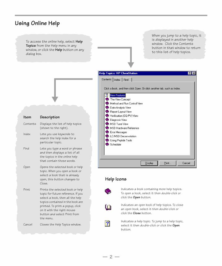
Using Online Help
To access the online help, select Help Topics from the Help menu in any window, or click the Help button on any dialog box.
Item Description
Contents Displays the list of help topics (shown to the right).
Index Lets you use keywords to search the help index for a particular topic.
Find Lets you type a word or phrase and then displays a list of all the topics in the online help that contain those words.
Open Opens the selected book or help topic. When you open a book or select a book that is already open, this button changes to Close.
Print Prints the selected book or help topic for future reference. If you select a book, then all the help topics contained in the book are printed. To print a popup, click on it with the right mouse button and select Print from the menu.
Cancel Closes the Help Topics window.
Indicates a book containing more help topics. To open a book, select it then double-click or click the Open button.
Indicates an open book of help topics. To close an open book, select it then double-click or click the Close button.
Indicates a help topic. To jump to a help topic, select it then double-click or click the Open button.
Help Icons
When you jump to a help topic, it is displayed in another help window. Click the Contents button in that window to return to this list of help topics.
Gsbook4pdf.fm Page 2 Thursday, May 14, 1998 8:45 AM
— 3 —
ChemStation Views
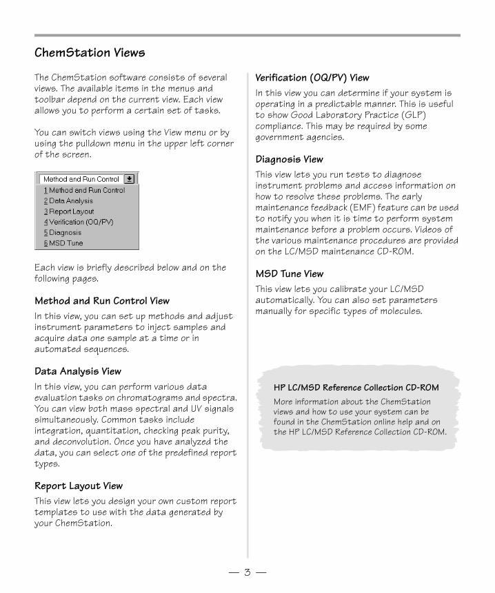
The ChemStation software consists of several views. The available items in the menus and toolbar depend on the current view. Each view allows you to perform a certain set of tasks.
You can switch views using the View menu or by using the pulldown menu in the upper left corner of the screen.
Each view is briefly described below and on the following pages.
Method and Run Control ViewIn this view, you can set up methods and adjust instrument parameters to inject samples and acquire data one sample at a time or in automated sequences.
Data Analysis ViewIn this view, you can perform various data evaluation tasks on chromatograms and spectra. You can view both mass spectral and UV signals simultaneously. Common tasks include integration, quantitation, checking peak purity, and deconvolution. Once you have analyzed the data, you can select one of the predefined report types.
Report Layout ViewThis view lets you design your own custom report templates to use with the data generated by your ChemStation.
Verification (OQ/PV) ViewIn this view you can determine if your system is operating in a predictable manner. This is useful to show Good Laboratory Practice (GLP) compliance. This may be required by some government agencies.
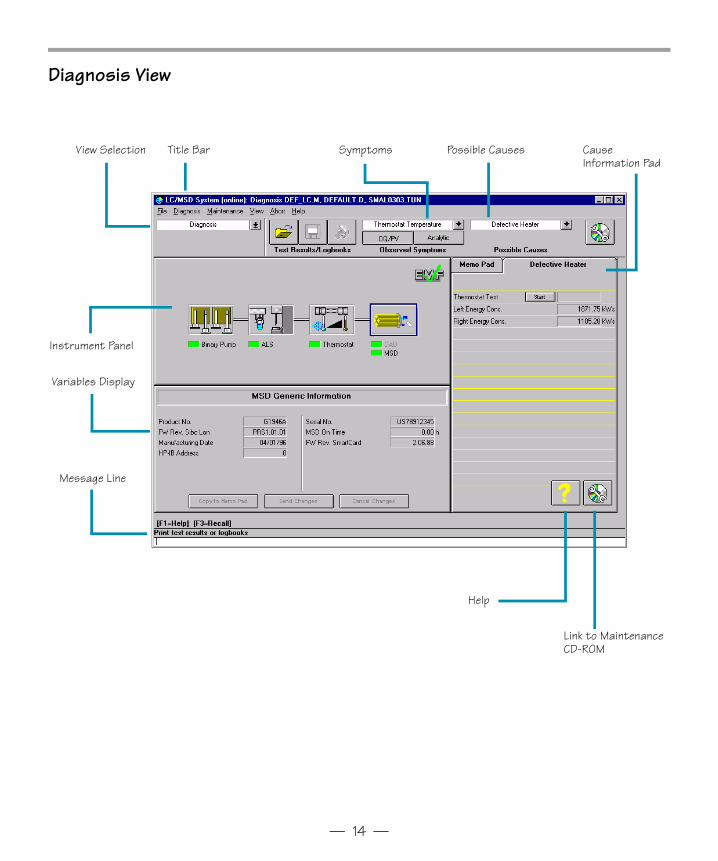
Diagnosis ViewThis view lets you run tests to diagnose instrument problems and access information on how to resolve these problems. The early maintenance feedback (EMF) feature can be used to notify you when it is time to perform system maintenance before a problem occurs. Videos of the various maintenance procedures are provided on the LC/MSD maintenance CD-ROM.
MSD Tune ViewThis view lets you calibrate your LC/MSD automatically. You can also set parameters manually for specific types of molecules.
HP LC/MSD Reference Collection CD-ROMMore information about the ChemStation views and how to use your system can be found in the ChemStation online help and on the HP LC/MSD Reference Collection CD-ROM.
Gsbook4pdf.fm Page 3 Thursday, May 14, 1998 8:45 AM
— 4 —
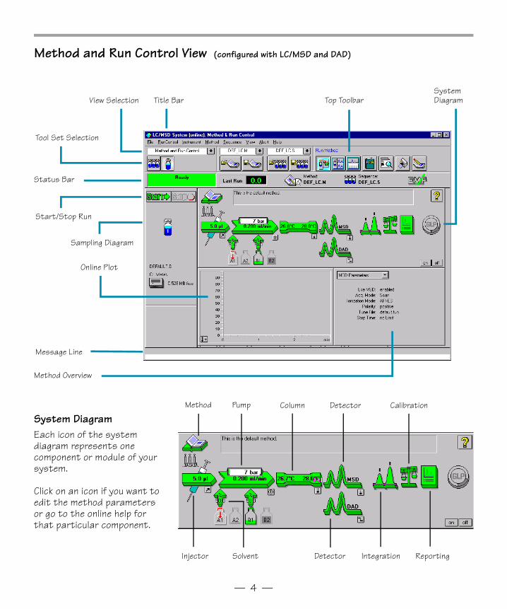
Method and Run Control View (configured with LC/MSD and DAD)
Title BarView Selection
Tool Set Selection
Message Line
Start/Stop Run
Sampling Diagram
Top ToolbarSystem Diagram
Status Bar
Online Plot
Method Overview
System DiagramEach icon of the system diagram represents one component or module of your system.
Click on an icon if you want to edit the method parameters or go to the online help for that particular component.
Method Pump Column Detector
DetectorInjector Solvent Integration
Calibration
Reporting
Gsbook4pdf.fm Page 4 Thursday, May 14, 1998 8:45 AM
— 5 —
Method Sequence
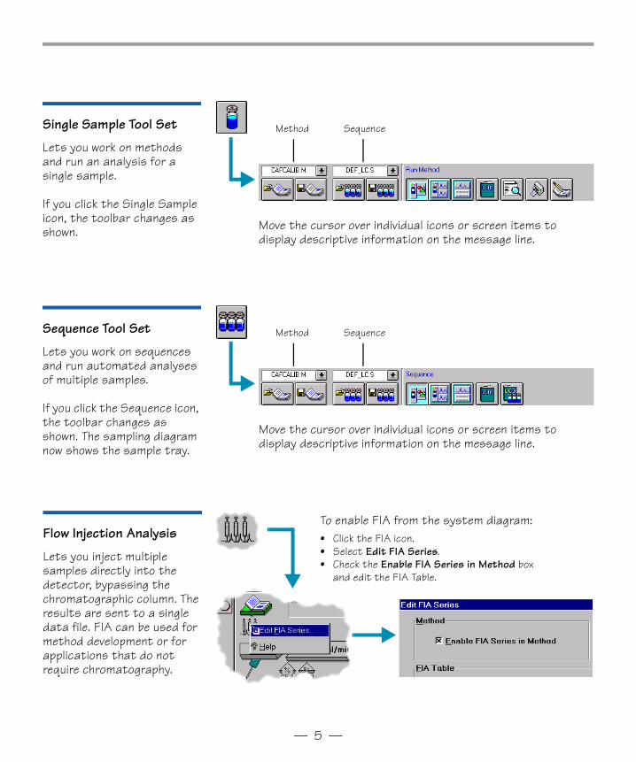
Move the cursor over individual icons or screen items to display descriptive information on the message line.
Move the cursor over individual icons or screen items to display descriptive information on the message line.
Method Sequence
Flow Injection Analysis
Lets you inject multiple samples directly into the detector, bypassing the chromatographic column. The results are sent to a single data file. FIA can be used for method development or for applications that do not require chromatography.
To enable FIA from the system diagram:• Click the FIA icon.• Select Edit FIA Series.• Check the Enable FIA Series in Method box
and edit the FIA Table.
Single Sample Tool Set
Lets you work on methods and run an analysis for a single sample.
If you click the Single Sample icon, the toolbar changes as shown.
Sequence Tool Set
Lets you work on sequences and run automated analyses of multiple samples.
If you click the Sequence icon, the toolbar changes as shown. The sampling diagram now shows the sample tray.
Gsbook4pdf.fm Page 5 Thursday, May 14, 1998 8:45 AM
— 6 —
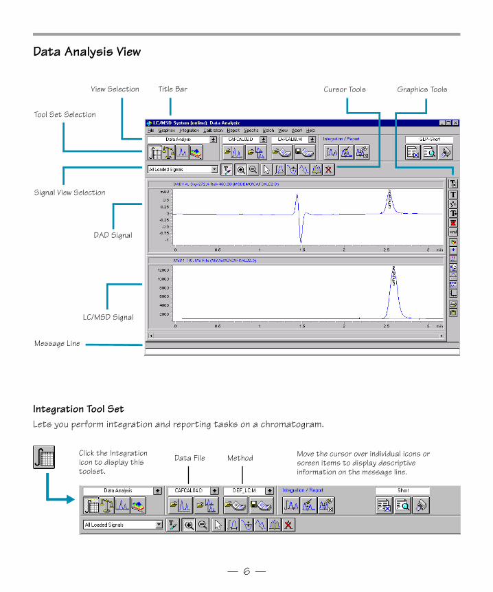
Data Analysis View
Integration Tool SetLets you perform integration and reporting tasks on a chromatogram.
Title BarView Selection Graphics Tools
Tool Set Selection
Cursor Tools
Signal View Selection
DAD Signal
LC/MSD Signal
Message Line
Data File Method Move the cursor over individual icons or screen items to display descriptive information on the message line.
Click the Integration icon to display this toolset.
Gsbook4pdf.fm Page 6 Thursday, May 14, 1998 8:45 AM
— 7 —
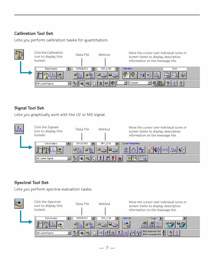
Calibration Tool SetLets you perform calibration tasks for quantitation.
Signal Tool SetLets you graphically work with the UV or MS signal.
Spectral Tool SetLets you perform spectra evaluation tasks.
Data File Method Move the cursor over individual icons or screen items to display descriptive information on the message line.
Click the Calibration icon to display this toolset.
Data File Method Move the cursor over individual icons or screen items to display descriptive information on the message line.
Click the Signals icon to display this toolset.
Data File Method Move the cursor over individual icons or screen items to display descriptive information on the message line.
Click the Spectral icon to display this toolset.
Gsbook4pdf.fm Page 7 Thursday, May 14, 1998 8:45 AM
— 8 —
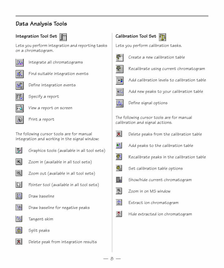
Data Analysis Tools
Integration Tool Set
Lets you perform integration and reporting tasks on a chromatogram.
Integrate all chromatograms
Find suitable integration events
Define integration events
Specify a report
View a report on screen
Print a report
The following cursor tools are for manual integration and working in the signal window:
Graphics tools (available in all tool sets)
Zoom in (available in all tool sets)
Zoom out (available in all tool sets)
Pointer tool (available in all tool sets)
Draw baseline
Draw baseline for negative peaks
Tangent skim
Split peaks
Delete peak from integration results
Calibration Tool Set
Lets you perform calibration tasks.
Create a new calibration table
Recalibrate using current chromatogram
Add calibration levels to calibration table
Add new peaks to your calibration table
Define signal options
The following cursor tools are for manual calibration and signal actions.
Delete peaks from the calibration table
Add peaks to the calibration table
Recalibrate peaks in the calibration table
Set calibration table options
Show/hide current chromatogram
Zoom in on MS window
Extract ion chromatogram
Hide extracted ion chromatogram
Gsbook4pdf.fm Page 8 Thursday, May 14, 1998 8:45 AM
— 9 —
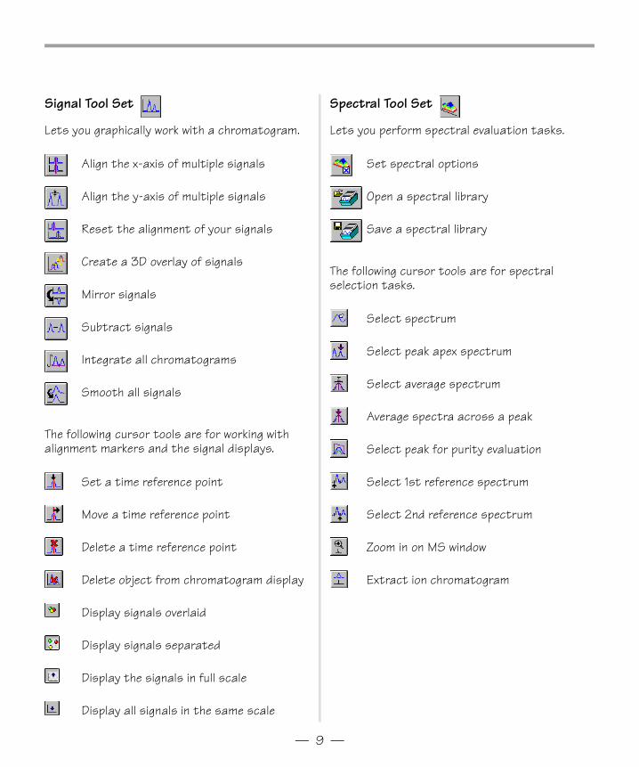
Signal Tool Set
Lets you graphically work with a chromatogram.
Align the x-axis of multiple signals
Align the y-axis of multiple signals
Reset the alignment of your signals
Create a 3D overlay of signals
Mirror signals
Subtract signals
Integrate all chromatograms
Smooth all signals
The following cursor tools are for working with alignment markers and the signal displays.
Set a time reference point
Move a time reference point
Delete a time reference point
Delete object from chromatogram display
Display signals overlaid
Display signals separated
Display the signals in full scale
Display all signals in the same scale
Spectral Tool Set
Lets you perform spectral evaluation tasks.
Set spectral options
Open a spectral library
Save a spectral library
The following cursor tools are for spectral selection tasks.
Select spectrum
Select peak apex spectrum
Select average spectrum
Average spectra across a peak
Select peak for purity evaluation
Select 1st reference spectrum
Select 2nd reference spectrum
Zoom in on MS window
Extract ion chromatogram
Gsbook4pdf.fm Page 9 Thursday, May 14, 1998 8:45 AM
— 10 —
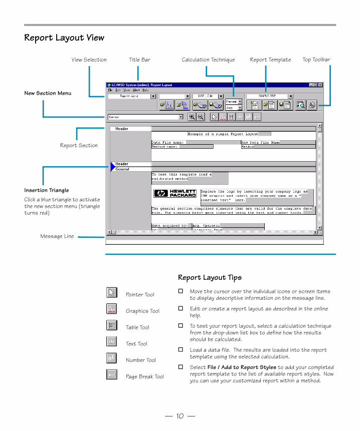
Report Layout View
Title BarView Selection Top Toolbar
New Section Menu
Message Line
Report TemplateCalculation Technique
Report Section
Insertion TriangleClick a blue triangle to activate the new section menu (triangle turns red)
Pointer Tool
Graphics Tool
Table Tool
Text Tool
Number Tool
Page Break Tool
Report Layout Tips
o Move the cursor over the individual icons or screen items to display descriptive information on the message line.
o Edit or create a report layout as described in the online help.
o To test your report layout, select a calculation technique from the drop-down list box to define how the results should be calculated.
o Load a data file. The results are loaded into the report template using the selected calculation.
o Select File / Add to Report Styles to add your completed report template to the list of available report styles. Now you can use your customized report within a method.
Gsbook4pdf.fm Page 10 Thursday, May 14, 1998 8:45 AM
— 11 —
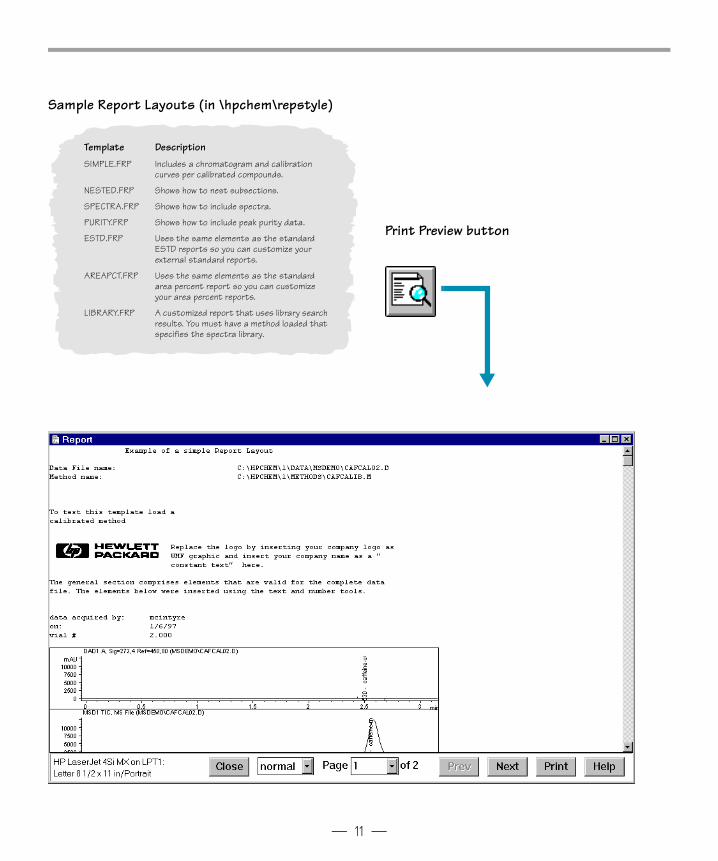
Sample Report Layouts (in \hpchem\repstyle)
Template DescriptionSIMPLE.FRP Includes a chromatogram and calibration
curves per calibrated compounds.
NESTED.FRP Shows how to nest subsections.
SPECTRA.FRP Shows how to include spectra.
PURITY.FRP Shows how to include peak purity data.
ESTD.FRP Uses the same elements as the standard ESTD reports so you can customize your external standard reports.
AREAPCT.FRP Uses the same elements as the standard area percent report so you can customize your area percent reports.
LIBRARY.FRP A customized report that uses library search results. You must have a method loaded that specifies the spectra library.
Print Preview button
Gsbook4pdf.fm Page 11 Thursday, May 14, 1998 8:45 AM
— 12 —
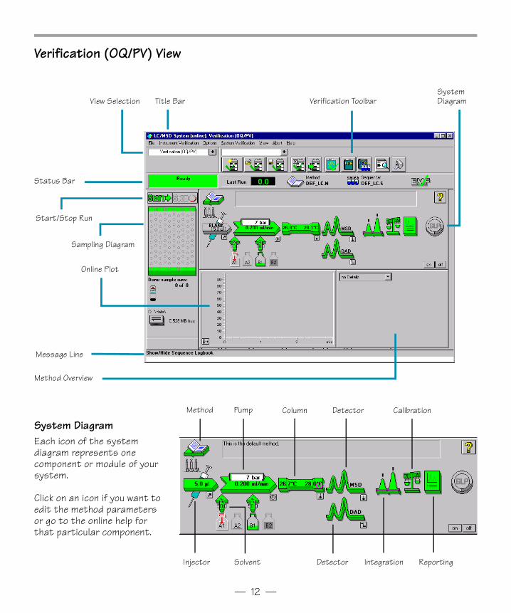
Verification (OQ/PV) View
Title BarView Selection
Message Line
Start/Stop Run
Sampling Diagram
Verification ToolbarSystem Diagram
Status Bar
Online Plot
Method Overview
System DiagramEach icon of the system diagram represents one component or module of your system.
Click on an icon if you want to edit the method parameters or go to the online help for that particular component.
Method Pump Column Detector
DetectorInjector Solvent Integration
Calibration
Reporting
Gsbook4pdf.fm Page 12 Thursday, May 14, 1998 8:45 AM
— 13 —
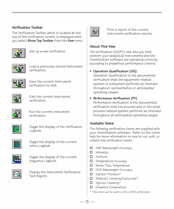
Verification ToolbarThe Verification Toolbar, which is located at the top of the Verification screen, is displayed when you select Show Top Toolbar from the View menu.
Set up a new verification.
Load a previously-stored instrument verification.
Save the current instrument verification to disk.
Edit the current instrument verification.
Run the current instrument verification.
Toggle the display of the Verification Logbook.
Toggle the display of the current online Logbook.
Toggle the display of the current Sequence Logbook.
Display the Instrument Verification Test Report.
About This ViewThe Verification (OQ/PV) view lets you test whether your analytical instruments and the ChemStation software are operating correctly according to predefined performance criteria.
• Operation Qualification (OQ)Operation Qualification is the documented verification that the equipment-related system or subsystem performs as intended throughout representative or anticipated operating ranges.
• Performance Verification (PV)Performance Verification is the documented verification that the process and or the total process-related system performs as intended throughout all anticipated operating ranges.
Available TestsThe following verification tests are supplied with your ChemStation software. Refer to the online help for more information on how to run, edit, or create new verification tests.
o VWD Wavelength Accuracyo Intensityo Holmiumo Temperature Accuracyo Noise, Flow, Temperatureo DAD Wavelength Accuracyo Injector Precision*o Detector Linearity/Carry-over*o Injector Linearity*o Gradient Composition* These tests can be used to verify LC/MSD performance.
Print a report of the current instrument verification results.
Gsbook4pdf.fm Page 13 Thursday, May 14, 1998 8:45 AM
— 14 —
Diagnosis View
Title BarView Selection
Message Line
Instrument Panel
Symptoms Cause Information Pad
Possible Causes
Variables Display
Link to Maintenance CD-ROM
Help
Gsbook4pdf.fm Page 14 Thursday, May 14, 1998 8:45 AM
— 15 —
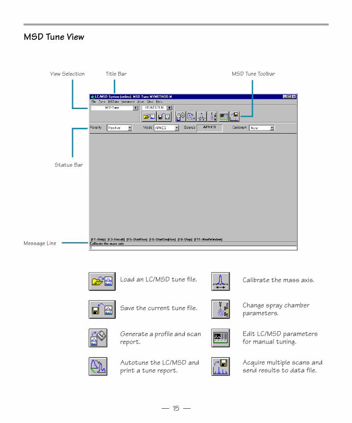
MSD Tune View
Title BarView Selection
Message Line
MSD Tune Toolbar
Status Bar
Load an LC/MSD tune file.
Save the current tune file.
Generate a profile and scan report.
Autotune the LC/MSD and print a tune report.
Calibrate the mass axis.
Change spray chamber parameters.
Edit LC/MSD parameters for manual tuning.
Acquire multiple scans and send results to data file.
Gsbook4pdf.fm Page 15 Thursday, May 14, 1998 8:45 AM
— 16 —
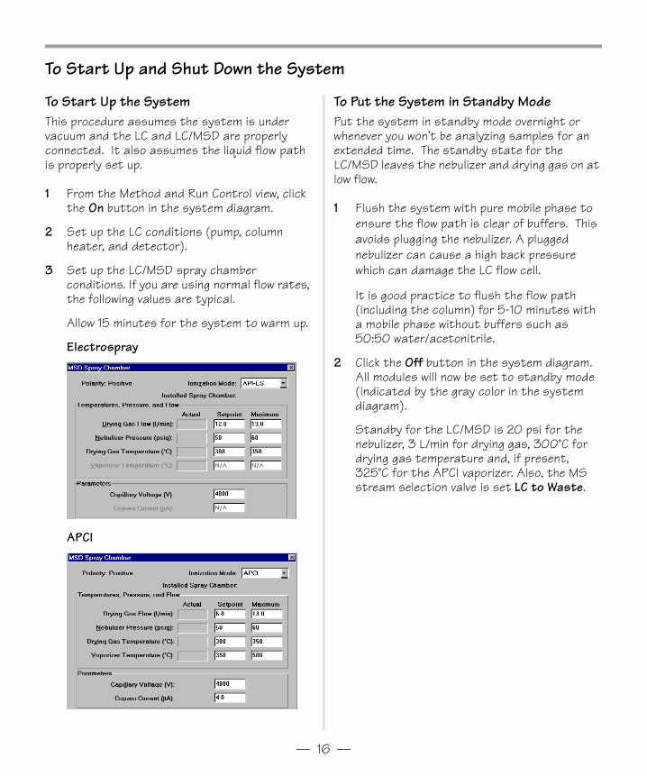
To Start Up and Shut Down the System
To Start Up the SystemThis procedure assumes the system is under vacuum and the LC and LC/MSD are properly connected. It also assumes the liquid flow path is properly set up.
1 From the Method and Run Control view, click the On button in the system diagram.
2 Set up the LC conditions (pump, column heater, and detector).
3 Set up the LC/MSD spray chamber conditions. If you are using normal flow rates, the following values are typical.
Allow 15 minutes for the system to warm up.
Electrospray
APCI
To Put the System in Standby ModePut the system in standby mode overnight or whenever you won’t be analyzing samples for an extended time. The standby state for the LC/MSD leaves the nebulizer and drying gas on at low flow.
1 Flush the system with pure mobile phase to ensure the flow path is clear of buffers. This avoids plugging the nebulizer. A plugged nebulizer can cause a high back pressure which can damage the LC flow cell.
It is good practice to flush the flow path (including the column) for 5-10 minutes with a mobile phase without buffers such as 50:50 water/acetonitrile.
2 Click the Off button in the system diagram. All modules will now be set to standby mode (indicated by the gray color in the system diagram).
Standby for the LC/MSD is 20 psi for the nebulizer, 3 L/min for drying gas, 300°C for drying gas temperature and, if present, 325°C for the APCI vaporizer. Also, the MS stream selection valve is set LC to Waste.
Gsbook4pdf.fm Page 16 Thursday, May 14, 1998 8:45 AM
— 17 —
To Tune the LC/MSD
What is Tuning?When the LC/MSD is used as a detector for the HPLC, a mass spectrum is associated with each data point in the LC chromatogram. To obtain high quality, accurate mass spectra, the LC/MSD must be optimized to:
• Maximize sensitivity • Maintain acceptable resolution• Ensure accurate mass assignment
Tuning is the process of adjusting LC/MSD parameters to achieve these goals. After the LC/MSD parameters have been optimized, they must be saved in a tune file (.tun). This tune file is then specified in the method that is used to acquire data for your samples.
Frequent tuning, automated or manual, is not required. Once tuned, the LC/MSD is very stable. Tuning should generally not be needed more often than monthly, or at most weekly.
Wait at least 4 hours after pumpdown before tuning or operating your LC/MSD. It takes the analyzer at least 4 hours to reach thermal equilibrium. Tune files created or data acquired before the LC/MSD is at thermal equilibrium may have incorrect mass assignments and other inaccuracies.
Using AutotuneUse autotune for automated adjustment of the LC/MSD performance.
1 From the MSD Tune view, select Tune / Autotune or click the Autotune icon.
2 Review the tune report which is printed automatically when tuning is completed.
Using Check TuneCheck Tune lets you quickly determine whether the LC/MSD is correctly tuned without performing a complete autotune. It performs a single profile scan of the tune masses and compares the peak widths and mass axes with target values.
1 Select Tune / Check Tune.
2 Review the Check Tune report. If any values are outside of acceptable ranges, Check Tune will suggest adjustments.
Using Manual TuneUse Manual Tune when you want to:• Achieve maximum sensitivity by sacrificing
some resolution
• Tune specifically for the very low end (<150 amu) of the mass range
• Tune with a compound other than the standard calibrants
Manual tuning involves 4 steps:
1 Optimizing ion transmission through the source ion optics (fragmentor, skim 2, lens 1, lens 2, octapole peak and octapole knee).
2 Setting the desired mass resolution (adjusting width gain and width offset).
3 Calibrating the mass axis (adjusting mass gain and mass offset).
4 Adjusting the signal strength (setting iris and adjusting the multiplier gain).
Note that fragmentor and gain are method parameters. The fragmentor affects ion transmission and fragmentation. For more information, see the online help.
Gsbook4pdf.fm Page 17 Thursday, May 14, 1998 8:45 AM
— 18 —
To Acquire LC/MS Data
Modes of AcquisitionThere are three modes of acquiring data:
• Running a method for a single sample• Running a sequence for multiple samples• Running an FIA series
Note the following about acquiring data:
• All three acquisition modes require an appropriate method.
• Samples may be injected either manually or with an ALS.
• A run must always be started from the software.
• An FIA method cannot be used in a sequence.
To Edit a Method and Start a RunOnce you know the acquisition mode you want to use, you need to set up an appropriate method. Methods are set up in the Method and Run Control view. New methods are created by editing existing ones.
1 Select Method / Load Method or click the Open Method button on the toolbar. Choose a method from the list.
2 Select Method / Edit Entire Method. This menu item is also available when you click the method icon on the system diagram.
Once you select to edit a method, a series of dialog boxes will be displayed that let you set up your method and instrument parameters.
Click the Help button on any of the following dialog boxes for descriptive information on the items available.
3 Select the method sections you want to edit (select all sections to become familiar with the method parameters that are available).
4 Add any method comments you want to appear on your reports.
5 Set up the instrument parameters:
– set up the pump parameters– set up the injector parameters– set up the DAD (or VWD) parameters– set up the column thermostat parameters– set up the MSD signals– set up the MSD spray chamber
6 Set up the Data Analysis parameters:
– set up the signal details– edit integration events– specify report parameters– select the instrument curves– select the calibration curves– set up the calibration table– find the ion parameters
7 Complete the Run Time Checklist.
8 Save the method using a different name. Select Method / Save Method As or click the Save Method button on the toolbar.
Once you are familiar with the options that are available, you can use the system diagram menus for quick access to particular method parameters, rather than using the edit entire method process.
9 When you are ready to begin a run, click the Start button.
Gsbook4pdf.fm Page 18 Thursday, May 14, 1998 8:45 AM
— 19 —
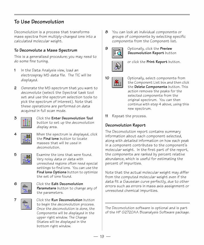
To Use Deconvolution
Deconvolution is a process that transforms mass spectra from multiply-charged ions into a calculated molecular weight.
To Deconvolute a Mass SpectrumThis is a generalized procedure; you may need to do some fine tuning.
1 In the Data Analysis view, load an electrospray MS data file. The TIC will be displayed.
2 Generate the MS spectrum that you want to deconvolute (select the Spectral task tool set and use the spectrum selection tools to pick the spectrum of interest). Note that these operations are performed on data acquired in full scan mode.
3 Click the Enter Deconvolution Tool button to set up the deconvolution display area.
4 When the spectrum is displayed, click the Find Ions button to locate masses that will be used in deconvolution.
5 Examine the ions that were found. Very noisy data or data with unresolved regions often need special settings to find ions. You can use the Find Ions Options button to optimize the set of ions found.
6 Click the Edit Deconvolution Parameters button to change any of the parameters.
7 Click the Run Deconvolution button to begin the deconvolution process. Once the deconvolution is done, the Components will be displayed in the upper right window. The Charge States will be displayed in the bottom right window.
8 You can look at individual components or groups of components by selecting specific components from the Component list.
9 Optionally, click the Preview Deconvolution Report button
or click the Print Report button.
10 Optionally, select components from the Component List box and then click the Delete Components button. This action removes the peaks for the selected components from the original spectrum. You can then continue with step 4 above, using this new spectrum.
11 Repeat the process.
Deconvolution ReportThe Deconvolution report contains summary information about each component selected, along with detailed information on how each peak in a component contributes to the component’s molecular weight. In the first part of the report, the components are ranked by percent relative abundance, which is useful for estimating the percent of impurities.
Note that the actual molecular weight may differ from the computed molecular weight even if the data fit a Gaussian curve perfectly, due to other errors such as errors in mass axis assignment or unresolved chemical impurities.
The Deconvolution software is optional and is part of the HP G2720AA Bioanalysis Software package.
Gsbook4pdf.fm Page 19 Thursday, May 14, 1998 8:45 AM
— 20 —
Operating Tips
Back up your data and methods regularly to avoid loss of data if the files are accidentally overwritten, deleted, or if a hardware problem develops with your disk drive.
Put the system in standby mode overnight or whenever you won’t be analyzing samples for an extended time.
Make sure the tune file you are using is appropriate for your samples.
Save Tune reports in an MS Logbook for future reference.
Regular system maintenance can reduce problems. Maintenance tasks are described on the HP 1100 Series LC/MSD Maintenance CD-ROM. Keep a maintenance record.
Use the Maintenance Logbook and EMF features (in the Diagnosis view) to help you keep track of when maintenance is needed and to keep an online maintenance record.
Flush the sample path and clean the spray chamber, capillary tip, and spray shield daily or at the end of each shift. Check the pump fluid level every week.
The spray chamber vent hose must be connected to a lab vent that is used only for the source (completely separate from the vent hose for the foreline pump). Otherwise, waste products can migrate into the spray chamber vent producing chemical noise.
Samples need to be filtered. They should be salt and detergent-free if no chromatography is used.
Use only filtered, HPLC-grade mobile phase.
If a UV detector is available, use it in series with the LC/MSD. Try to minimize chromatographic peak broadening by using low dispersion tubing.
To avoid chromatographic band broadening, make sure all tubing connections are free of dead volume. Use zero dead-volume (ZDV) fittings when possible. If using fingertight fittings, force tubing into unions and tees while tightening the fittings.
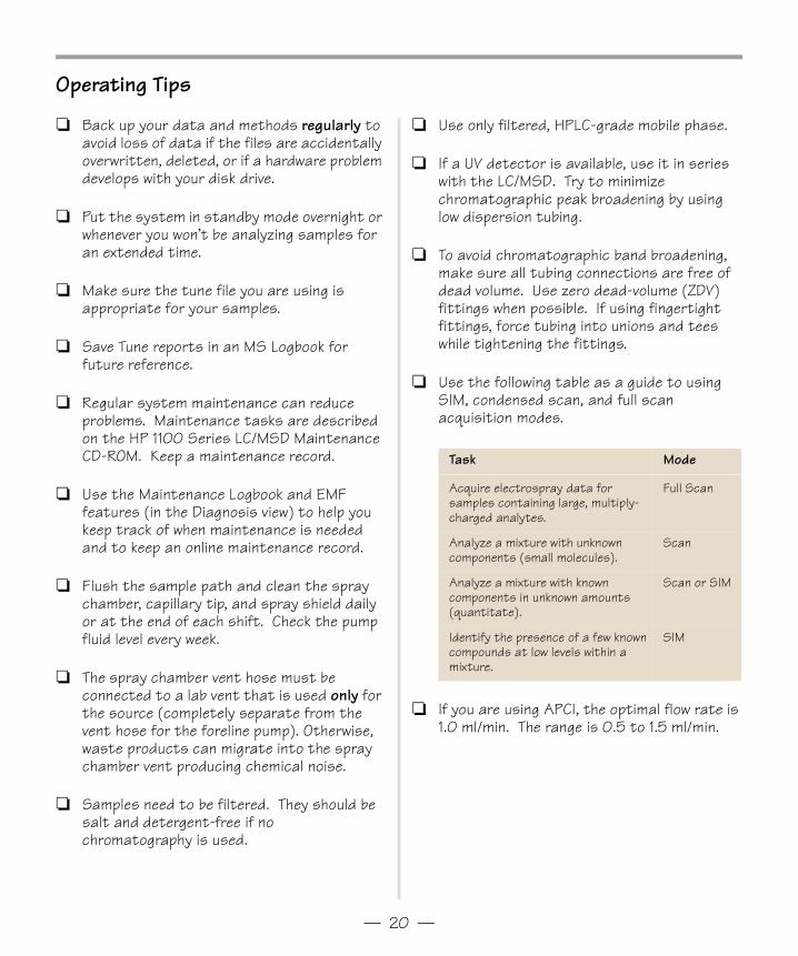
Use the following table as a guide to using SIM, condensed scan, and full scan acquisition modes.
If you are using APCI, the optimal flow rate is 1.0 ml/min. The range is 0.5 to 1.5 ml/min.
Task Mode
Acquire electrospray data for samples containing large, multiply-charged analytes.
Full Scan
Analyze a mixture with unknown components (small molecules).
Scan
Analyze a mixture with known components in unknown amounts (quantitate).
Scan or SIM
Identify the presence of a few known compounds at low levels within a mixture.
SIM
Gsbook4pdf.fm Page 20 Thursday, May 14, 1998 8:45 AM
— 21 —
Troubleshooting Tips
No peaks
o Make sure there is spray from the nebulizer.o Make sure the capillary voltage is set correctly.o Make sure the LC/MSD is tuned correctly.o Make sure LC/MSD pressures are within normal
ranges.o Check the drying gas flow and temperature.o Make sure the fragmentor is set correctly.
Poor mass accuracy
o Recalibrate the mass axis.o Make sure the ions used for tuning span the
mass range of the sample ions and that they show strong, stable signals.
Low signal
o Check the solution chemistry. Make sure the solvent you’re using is appropriate for your sample. Mixed samples can exhibit signal suppression of one or more components.
o Make sure the sample is fresh and has been stored correctly.
o Make sure the LC/MSD is tuned correctly.o Check the nebulizer condition.o Clean the capillary entrance.o Check the capillary for damage and
contamination.
Unstable signal
o Make sure the drying gas flow and temperature are correct for the solvent flow you are using.
o Make sure the solvent is thoroughly degassed. Do not use ultrasonic degassing with protein samples.
o Make sure the LC backpressure is steady; this indicates a steady solvent flow.
High spectral noise
o Use appropriate mass filter values.o Check the spray shape. Nebulizer may be
damaged or incorrectly set.o Make sure drying gas flow and temperature are
correct for the solvent flow you are using.o Make sure the solvent is thoroughly degassed.
Do not use ultrasonic degassing with protein samples.
o Make sure the LC backpressure is steady; this indicates a steady solvent flow.
o If you are using water as part of the mobile phase, make sure it is de-ionized (>18MΩ).
Droplets, not spray, exiting the nebulizer
o Make sure the nebulizing gas pressure is set high enough for the LC flow being used.
o Check the position of the needle in the nebulizer.o Stop the solvent flow and remove the nebulizer
assembly. Use a magnifying glass to examine the end of the nebulizer for damage.
No flow
o Make sure the LC is on and there is sufficient solvent in the correct bottle.
o Check for LC error messages.o Check for blockages. Repair or replace any
blocked components.o Check for leaks.o Make sure the MS stream selector valve is set
to LC to MSD.
Undesired fragmentation
o Fragmentor is set too high.o Ionization is causing fragmentation (APCI vs.
Electrospray).o APCI temperature is too high.
Gsbook4pdf.fm Page 21 Thursday, May 14, 1998 8:45 AM
— 22 —
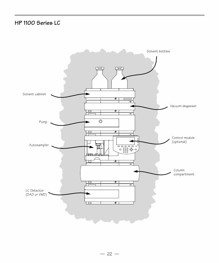
HP 1100 Series LC
Solvent bottles
LC Detector (DAD or VWD)
Control module(optional)
Vacuum degasser
Pump
Solvent cabinet
Column compartment
Autosampler
Gsbook4pdf.fm Page 22 Thursday, May 14, 1998 8:45 AM
— 23 —
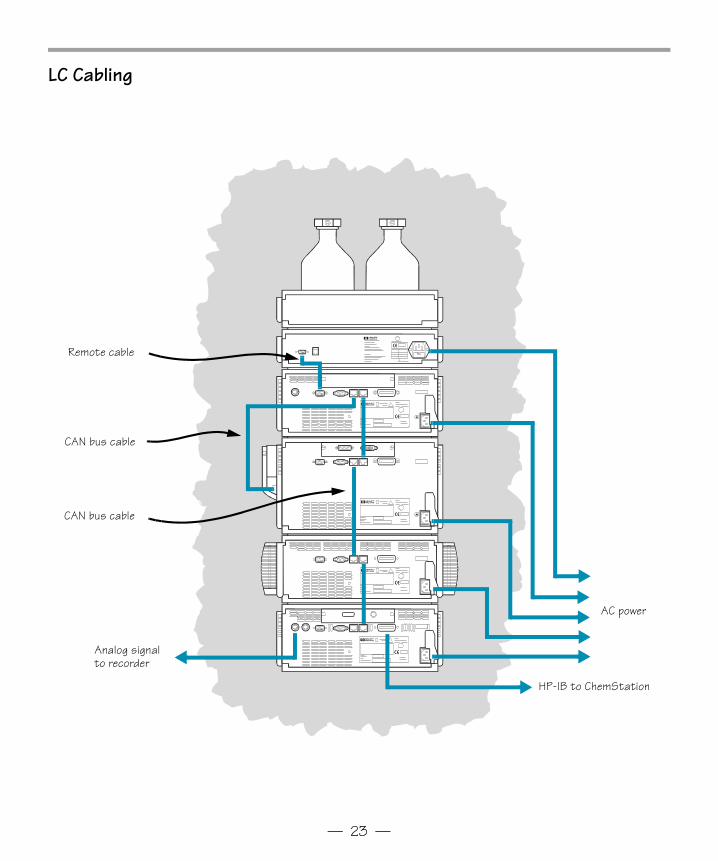
LC Cabling
Remote cable
CAN bus cable
AC power
HP-IB to ChemStation
CAN bus cable
Analog signal to recorder
Gsbook4pdf.fm Page 23 Thursday, May 14, 1998 8:45 AM
— 24 —
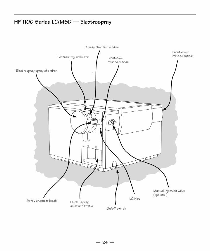
HP 1100 Series LC/MSD — Electrospray
Electrospray calibrant bottle
On/off switch
Spray chamber latch
Electrospray spray chamber
Electrospray nebulizer
Spray chamber window
Front cover release button
Front cover release button
Manual injection valve (optional)
LC inlet
Gsbook4pdf.fm Page 24 Thursday, May 14, 1998 8:45 AM
— 25 —
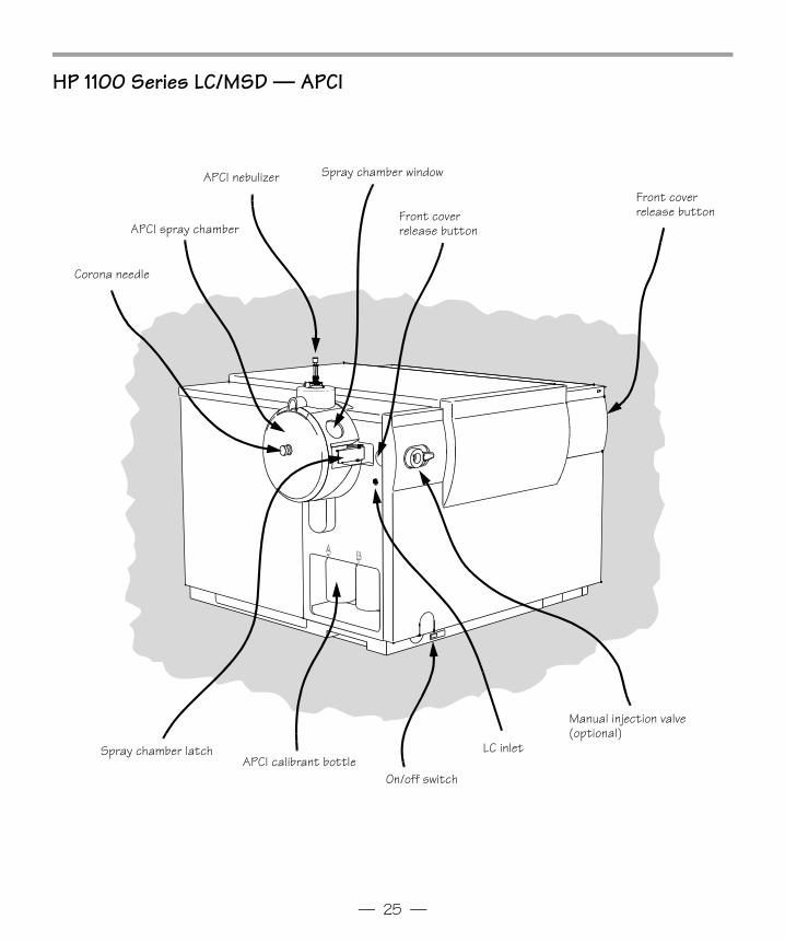
HP 1100 Series LC/MSD — APCI
APCI calibrant bottleOn/off switch
Spray chamber latch
APCI spray chamber
APCI nebulizer Spray chamber window
Front cover release button
Front cover release button
Manual injection valve (optional)
Corona needle
LC inlet
Gsbook4pdf.fm Page 25 Thursday, May 14, 1998 8:45 AM
— 26 —
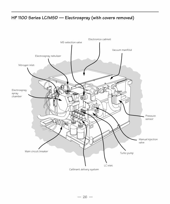
HP 1100 Series LC/MSD — Electrospray (with covers removed)
Electronics cabinetMS selection valve
Electrospray nebulizer
Vacuum manifold
Nitrogen inlet
Electrosprayspray chamber
Main circuit breaker
Calibrant delivery systemLC inlet
Turbo pump
Manual injection valve
Pressure sensor
Gsbook4pdf.fm Page 26 Thursday, May 14, 1998 8:45 AM
— 27 —
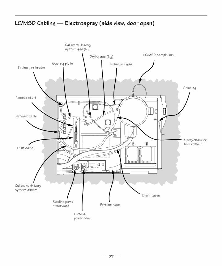
LC/MSD Cabling — Electrospray (side view, door open)
LC/MSD sample line
Remote start
Gas supply in
HP-IB cable
Foreline pump power cord Foreline hose
Drain tubes
LC/MSD power cord
LC tubing
Calibrant delivery system control
Network cable
Drying gas heater
Calibrant delivery system gas (N2)
Drying gas (N2)
Nebulizing gas
Spray chamber high voltage
Gsbook4pdf.fm Page 27 Thursday, May 14, 1998 8:45 AM
— 28 —
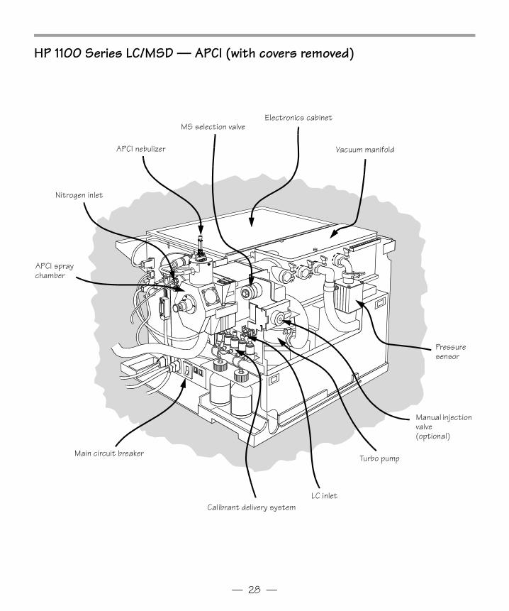
HP 1100 Series LC/MSD — APCI (with covers removed)
Electronics cabinetMS selection valve
APCI nebulizer Vacuum manifold
Nitrogen inlet
APCI spray chamber
Main circuit breaker
Calibrant delivery systemLC inlet
Turbo pump
Manual injection valve(optional)
Pressure sensor
Gsbook4pdf.fm Page 28 Thursday, May 14, 1998 8:45 AM
— 29 —
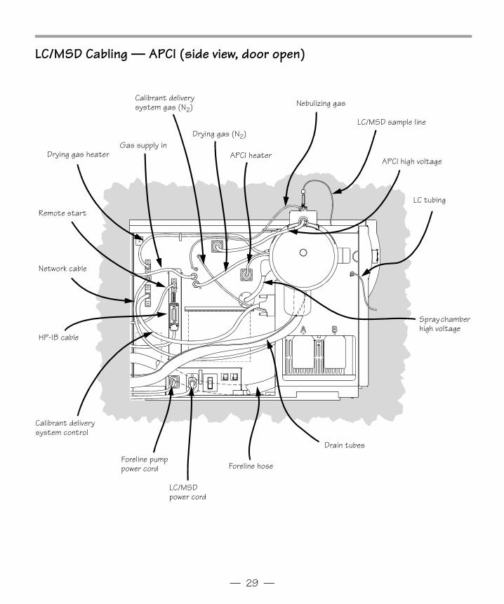
LC/MSD Cabling — APCI (side view, door open)
LC/MSD sample line
Remote start
Gas supply in
HP-IB cable
Foreline pump power cord Foreline hose
Drain tubes
LC/MSD power cord
LC tubing
Calibrant delivery system control
Network cable
Drying gas heater
Calibrant delivery system gas (N2)
Drying gas (N2)
Nebulizing gas
Spray chamber high voltage
APCI heaterAPCI high voltage
Gsbook4pdf.fm Page 29 Thursday, May 14, 1998 8:45 AM
— 30 —
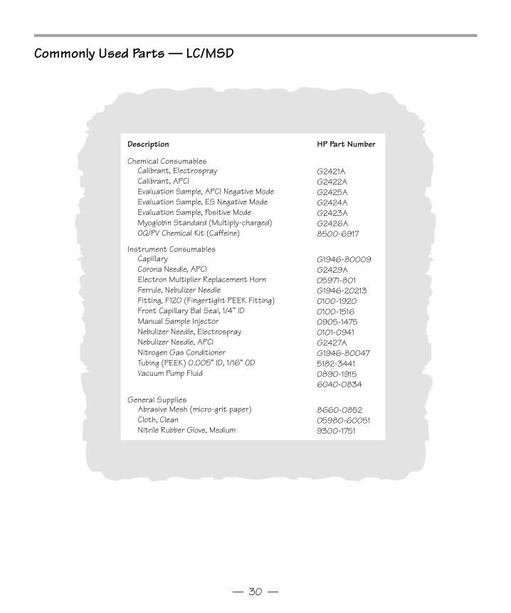
Commonly Used Parts — LC/MSD
Description HP Part Number
Chemical ConsumablesCalibrant, ElectrosprayCalibrant, APCIEvaluation Sample, APCI Negative ModeEvaluation Sample, ES Negative ModeEvaluation Sample, Positive ModeMyoglobin Standard (Multiply-charged)OQ/PV Chemical Kit (Caffeine)
G2421AG2422AG2425AG2424AG2423AG2426A8500-6917
Instrument ConsumablesCapillaryCorona Needle, APCIElectron Multiplier Replacement HornFerrule, Nebulizer NeedleFitting, F120 (Fingertight PEEK Fitting)Front Capillary Bal Seal, 1/4” IDManual Sample InjectorNebulizer Needle, ElectrosprayNebulizer Needle, APCINitrogen Gas ConditionerTubing (PEEK) 0.005” ID, 1/16” ODVacuum Pump Fluid
G1946-80009G2429A05971-801G1946-202130100-19200100-15160905-14750101-0941G2427AG1946-800475182-34410890-19156040-0834
General SuppliesAbrasive Mesh (micro-grit paper)Cloth, CleanNitrile Rubber Glove, Medium
8660-085205980-600519300-1751
Gsbook4pdf.fm Page 30 Thursday, May 14, 1998 8:45 AM
— 31 —
Safety Warnings
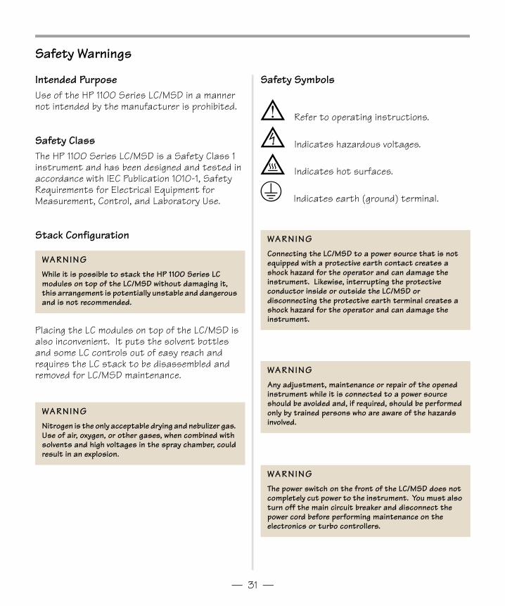
Intended PurposeUse of the HP 1100 Series LC/MSD in a manner not intended by the manufacturer is prohibited.
Safety ClassThe HP 1100 Series LC/MSD is a Safety Class 1 instrument and has been designed and tested in accordance with IEC Publication 1010-1, Safety Requirements for Electrical Equipment for Measurement, Control, and Laboratory Use.
Stack Configuration
Placing the LC modules on top of the LC/MSD is also inconvenient. It puts the solvent bottles and some LC controls out of easy reach and requires the LC stack to be disassembled and removed for LC/MSD maintenance.
WARNINGWhile it is possible to stack the HP 1100 Series LC modules on top of the LC/MSD without damaging it, this arrangement is potentially unstable and dangerous and is not recommended.
WARNINGNitrogen is the only acceptable drying and nebulizer gas. Use of air, oxygen, or other gases, when combined with solvents and high voltages in the spray chamber, could result in an explosion.
Safety Symbols
; Refer to operating instructions.
= Indicates hazardous voltages.
+ Indicates hot surfaces.
3 Indicates earth (ground) terminal.
WARNINGConnecting the LC/MSD to a power source that is not equipped with a protective earth contact creates a shock hazard for the operator and can damage the instrument. Likewise, interrupting the protective conductor inside or outside the LC/MSD or disconnecting the protective earth terminal creates a shock hazard for the operator and can damage the instrument.
WARNINGAny adjustment, maintenance or repair of the opened instrument while it is connected to a power source should be avoided and, if required, should be performed only by trained persons who are aware of the hazards involved.
WARNINGThe power switch on the front of the LC/MSD does not completely cut power to the instrument. You must also turn off the main circuit breaker and disconnect the power cord before performing maintenance on the electronics or turbo controllers.
Gsbook4pdf.fm Page 31 Thursday, May 14, 1998 8:45 AM

Document History
First Edition, 5/98HP G2710 LC/MSD ChemStation Software, Rev. A.06.01 and later until superseded
Copyright © 1998Hewlett-Packard CompanyPrinted in U.S.A. 5/98
*G1946-90035**G1946-90035*
Manual Part NumberG1946-90035
H
Gsbook4pdf.fm Page 32 Thursday, May 14, 1998 8:45 AM