Embed Size (px)
Citation preview

Advancements in Force Transfer Around Openings for Wood Framed Shear Walls
Karyn Beebe, P.E., LEED AP Disclaimer: This presentation was developed by a third party and is not funded by WoodWorks or the
Softwood Lumber Board.

“The Wood Products Council” is a Registered Provider with The American Ins<tute of Architects Con<nuing Educa<on Systems (AIA/CES), Provider #G516.
Credit(s) earned on comple<on of this course will be reported to AIA CES for AIA members. Cer<ficates of Comple<on for both AIA members and non-‐AIA members are available upon request.
This course is registered with AIA CES for con<nuing professional educa<on. As such, it does not include content that may be deemed or construed to be an approval or endorsement by the AIA of any material of construc<on or any method or manner of handling, using, distribu<ng, or dealing in any material or product.
______________________________ Ques<ons related to specific materials,
methods, and services will be addressed at the conclusion of this presenta<on.

Course Description
A joint research project of APA – The Engineered Wood Association, University of British Columbia (UBC), and USDA Forest Products Laboratory was initiated in 2009 to examine the variations of walls with code-allowable openings. Test results from the (8' x 12') full-scale wall configurations, in conjunction with the analytical results from a computer model developed by UBC, were used to develop and refine rational design methodologies in accordance with the International Building Code (IBC). This presentation provides an update of that research with a focus on asymmetric piers and multiple openings. Rational design methodologies in accordance with the IBC (and California Building Code) will be shared.

Learning Objectives
1. Investigate past and current methods for determining force transfer around openings for wood shear walls.
2. Compare the effects of different sizes of openings and full-height piers, and their relationships to the three industry standards for calculation of force transfer around openings.
3. Assess new design methodologies for accurately estimating the forces around multiple openings with asymmetric piers.
4. Estimate the deflections for shear walls designed using the force transfer around openings design method.

Agenda
Shear Wall Design Challenges History of FTAO Research at APA Advancements in FTAO § Asymmetric Pier Widths § Multiple Openings § C-shaped Panels § Deflection Calculations § Conceptual Keys § Benefits

Shear Wall Design Challenges
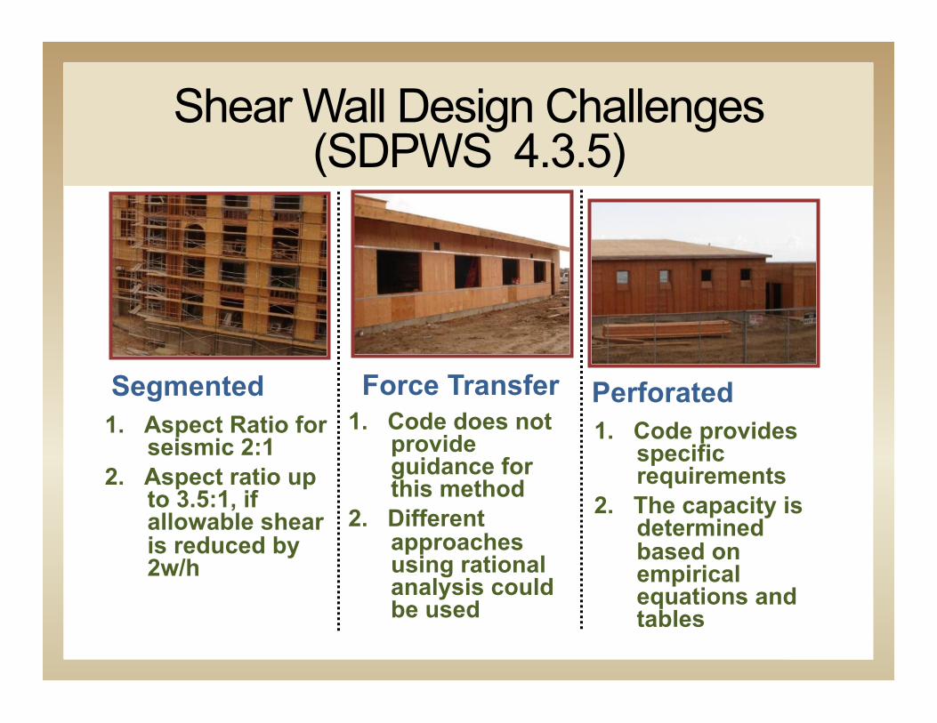
Shear Wall Design Challenges (SDPWS 4.3.5)
Segmented 1. Aspect Ratio for
seismic 2:1 2. Aspect ratio up
to 3.5:1, if allowable shear is reduced by 2w/h
Force Transfer 1. Code does not
provide guidance for this method
2. Different approaches using rational analysis could be used
Perforated 1. Code provides
specific requirements
2. The capacity is determined based on empirical equations and tables
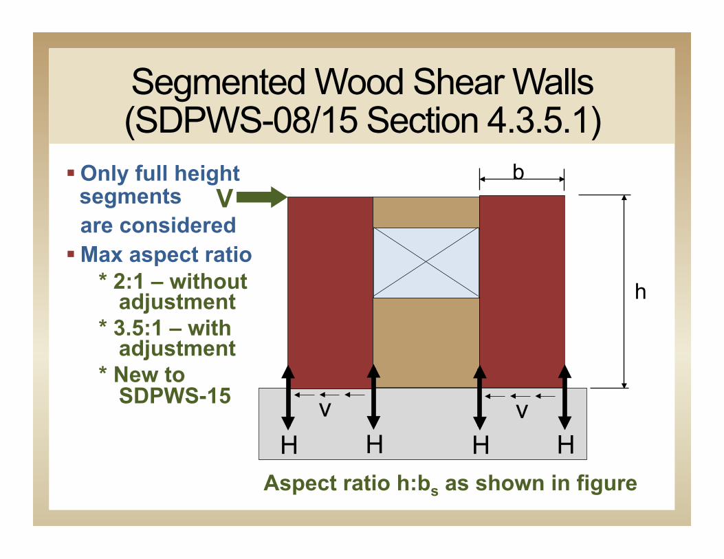
Segmented Wood Shear Walls (SDPWS-08/15 Section 4.3.5.1)
H H H H v v
V
h
b § Only full height segments are considered § Max aspect ratio
* 2:1 – without adjustment
* 3.5:1 – with adjustment
* New to SDPWS-15
Aspect ratio h:bs as shown in figure

FTAO (SDPWS-08/15 Section 4.3.5.2)
H H v
V
h
b § Openings accounted for by strapping or framing § “based on a
rational analysis” § Hold-downs only at ends
§ H/w ratio defined by wall pier
Aspect ratio h:b as shown in figure
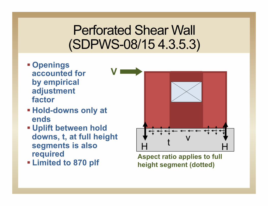
Perforated Shear Wall (SDPWS-08/15 4.3.5.3)
§ Openings accounted for by empirical adjustment factor
§ Hold-downs only at ends
§ Uplift between hold downs, t, at full height segments is also required
§ Limited to 870 plf Aspect ratio applies to full height segment (dotted)
H H v t
V

Aspect ratio (SDPWS-15 4.3.4.2)
§ Definition of h and w is the same as previous code
§ ALL shear walls with 2:1 < aspect ratios <= 3.5:1 shall apply reduction factor, aspect ratio factor
§ Aspect Ratio Factor (WSP) = 1.25-0.125h/bs § Formerly applied only to high seismic
Excerpt Fig. 4E h:w ratio FTAO
Excerpt Fig 4D h:w ratio Segmented
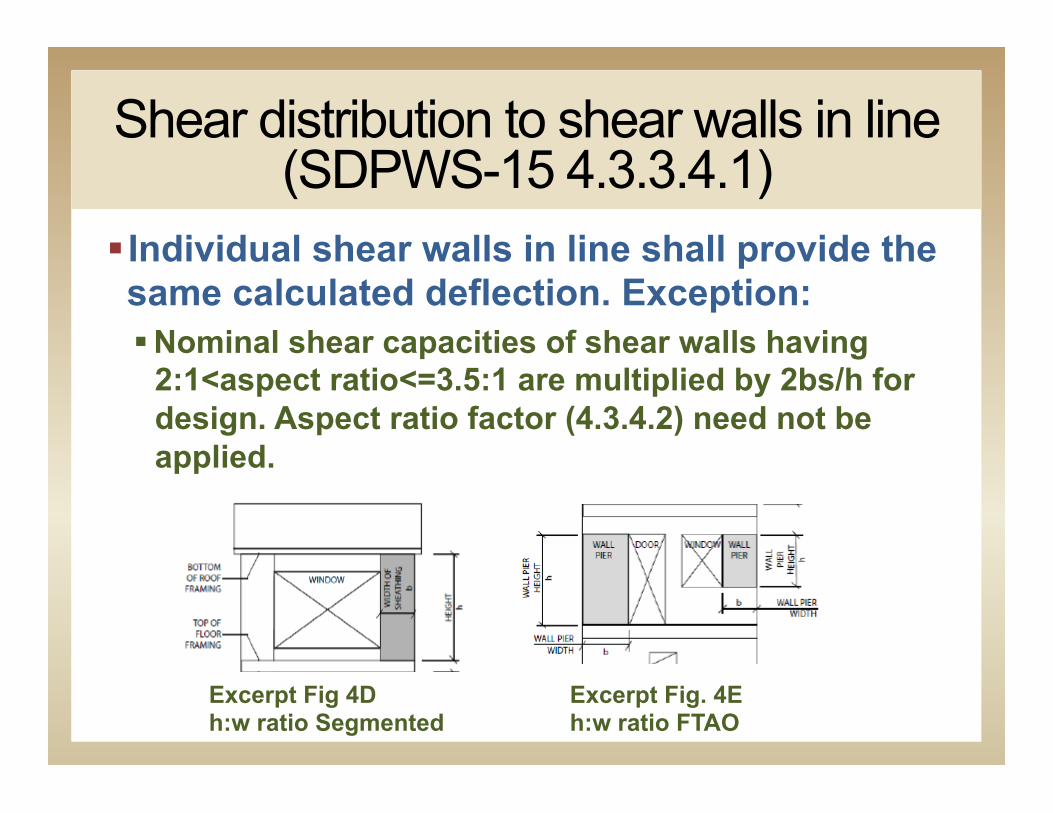
Shear distribution to shear walls in line (SDPWS-15 4.3.3.4.1)
§ Individual shear walls in line shall provide the same calculated deflection. Exception: § Nominal shear capacities of shear walls having
2:1<aspect ratio<=3.5:1 are multiplied by 2bs/h for design. Aspect ratio factor (4.3.4.2) need not be applied.
Excerpt Fig. 4E h:w ratio FTAO
Excerpt Fig 4D h:w ratio Segmented
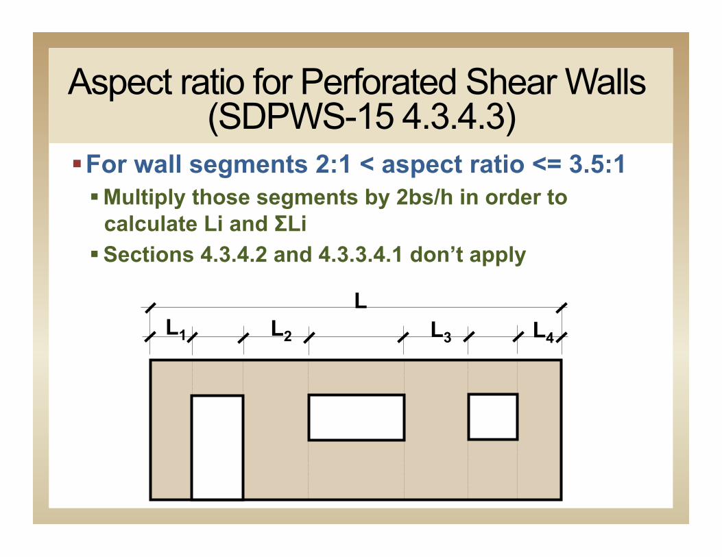
Aspect ratio for Perforated Shear Walls (SDPWS-15 4.3.4.3)
§ For wall segments 2:1 < aspect ratio <= 3.5:1 § Multiply those segments by 2bs/h in order to
calculate Li and ΣLi § Sections 4.3.4.2 and 4.3.3.4.1 don’t apply
L1 L2 L3 L4
L

Shear Wall Design Challenges
Typical FTAO Application § Residential, Multifamily
§ Single Opening § Design assumes equal pier width
§ Commercial § Strap continuous wall line above and below openings § Fully sheath wall
Field Survey § 18+ sites fall 2010 (LA, Orange and San Diego
Counties) § Multi-Family
§ 40-90% of all shear applications utilized FTAO § Single-Family
§ 80% Minimum 1-application on front or back elevation § 70% Multiple applications on front, back or both § 25% Side wall application in addition to front or back application

History of FTAO Research at APA
Joint research project § APA - The Engineered Wood Association (Skaggs & Yeh) § University of British Columbia (Lam & Li), § USDA Forest Products Laboratory (Rammer & Wacker)
Study was initiated in 2009 to: § Examine the variations of walls with code-allowable
openings § Examines the internal forces generated during full-scale
testing § Evaluate the effects of size of openings, size of full-height
piers, and different construction techniques § Create analytical modeling to mimic testing data

Research Overview Study results will be used to:
§ Support design methodologies in estimating the forces around the openings
§ Develop rational design methodologies for adoption in the building codes and supporting standards
§ Create new tools/methodology for designers to facilitate use of FTAO
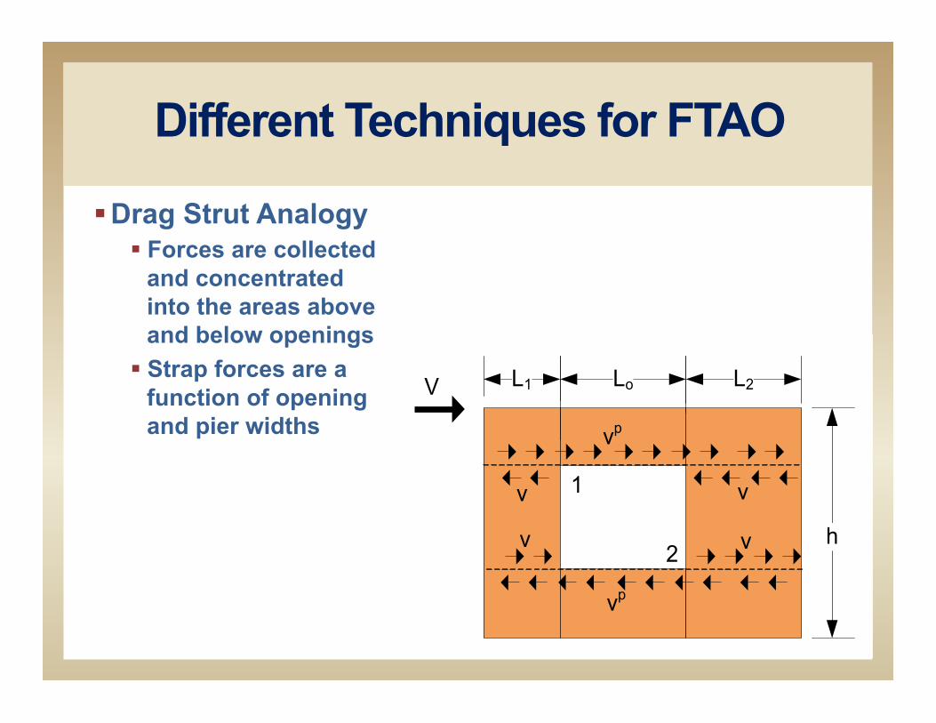
Different Techniques for FTAO
§ Drag Strut Analogy § Forces are collected
and concentrated into the areas above and below openings
§ Strap forces are a function of opening and pier widths
L1 Lo L2
h
V
vp
v v
vp
v v
1
2

Different Techniques for FTAO
§ Cantilever Beam Analogy § Forces are treated as
moment couples § Segmented panels
are piers at sides of openings
§ Strap forces are a function of height above and below opening and pier widths
ho/2 F1
V1
L1
h1
ho/2F2
V2
L2
hU1
2
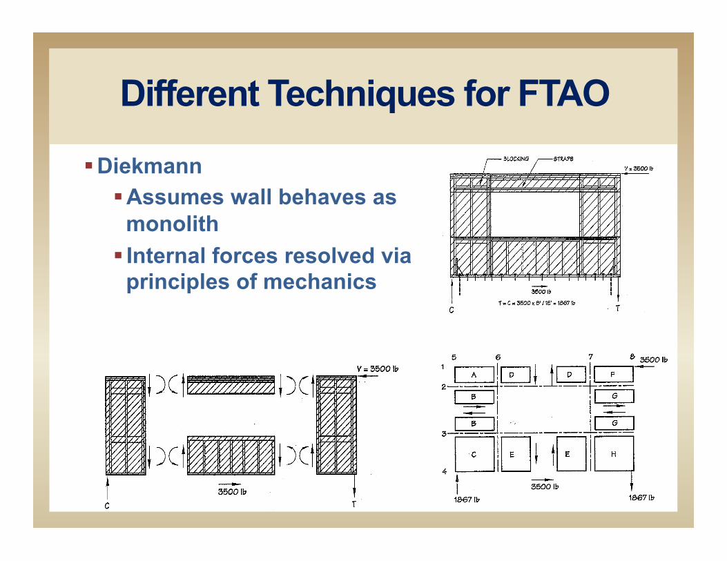
Different Techniques for FTAO
§ Diekmann § Assumes wall behaves as
monolith § Internal forces resolved via
principles of mechanics
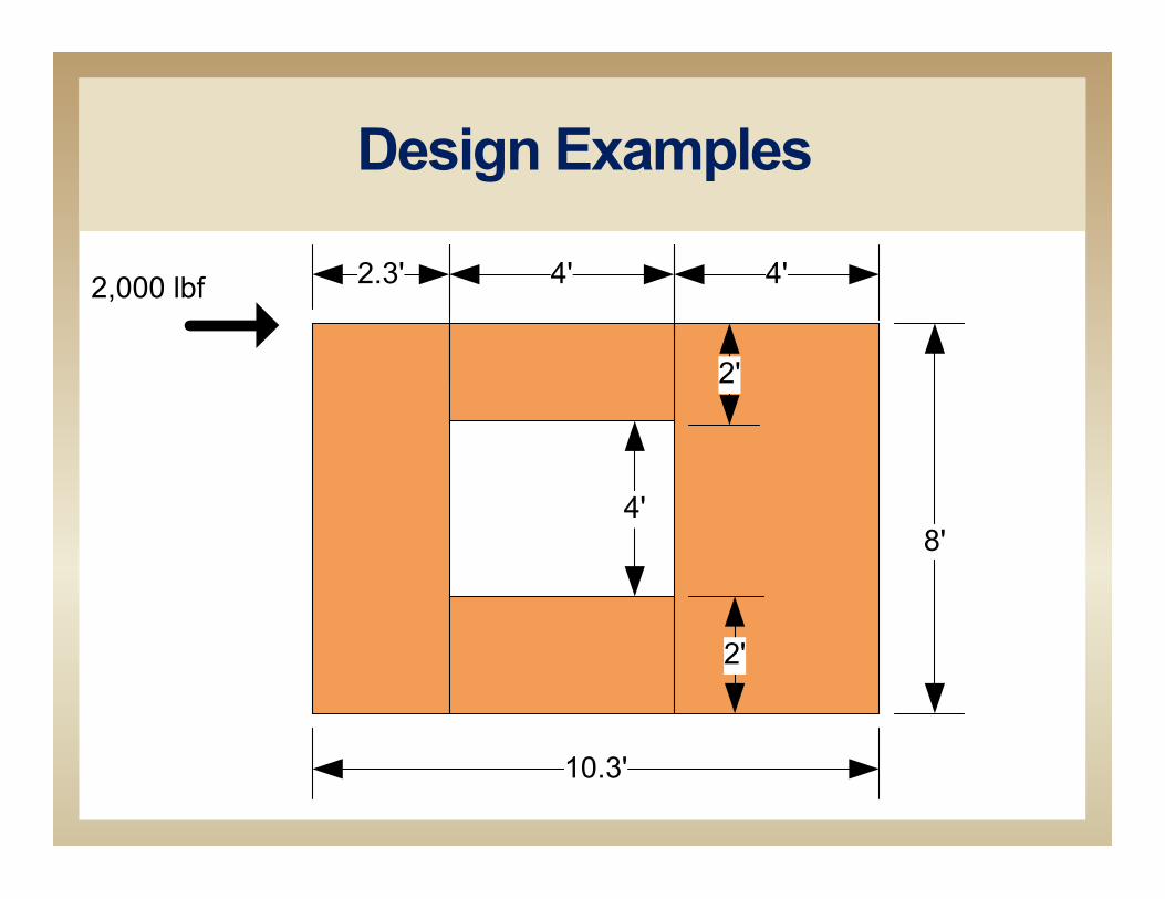
Design Examples
2.3' 4' 4'
8'4'
2'
2,000 lbf
2'
10.3'
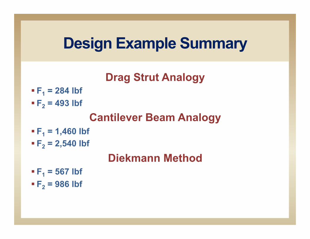
Design Example Summary
Drag Strut Analogy § F1 = 284 lbf § F2 = 493 lbf
Cantilever Beam Analogy § F1 = 1,460 lbf § F2 = 2,540 lbf
Diekmann Method § F1 = 567 lbf § F2 = 986 lbf

References Drag Strut Analogy
§ Martin, Z.A. 2005. Design of wood structural panel shear walls with openings: A comparison of methods. Wood Design Focus 15(1):18-20
Cantilever Beam Analogy § Martin, Z.A. (see above)
Diekmann Method § Diekmann, E. K. 2005. Discussion and Closure (Martin, above),
Wood Design Focus 15(3): 14-15 § Breyer, D.E., K.J. Fridley, K.E. Cobeen and D. G. Pollock. 2007.
Design of wood structures ASD/LRFD, 6th ed. McGraw Hill, New York.
SEAOC/Thompson Method § SEAOC. 2007. 2006 IBC Structural/Seismic Design Manual,
Volume 2: Building Design Examples for Light-frame, Tilt-up Masonry. Structural Engineers Association of California, Sacramento, CA
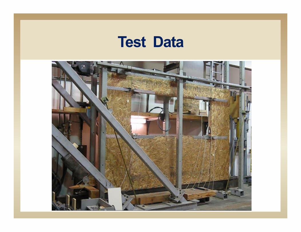
Test Data
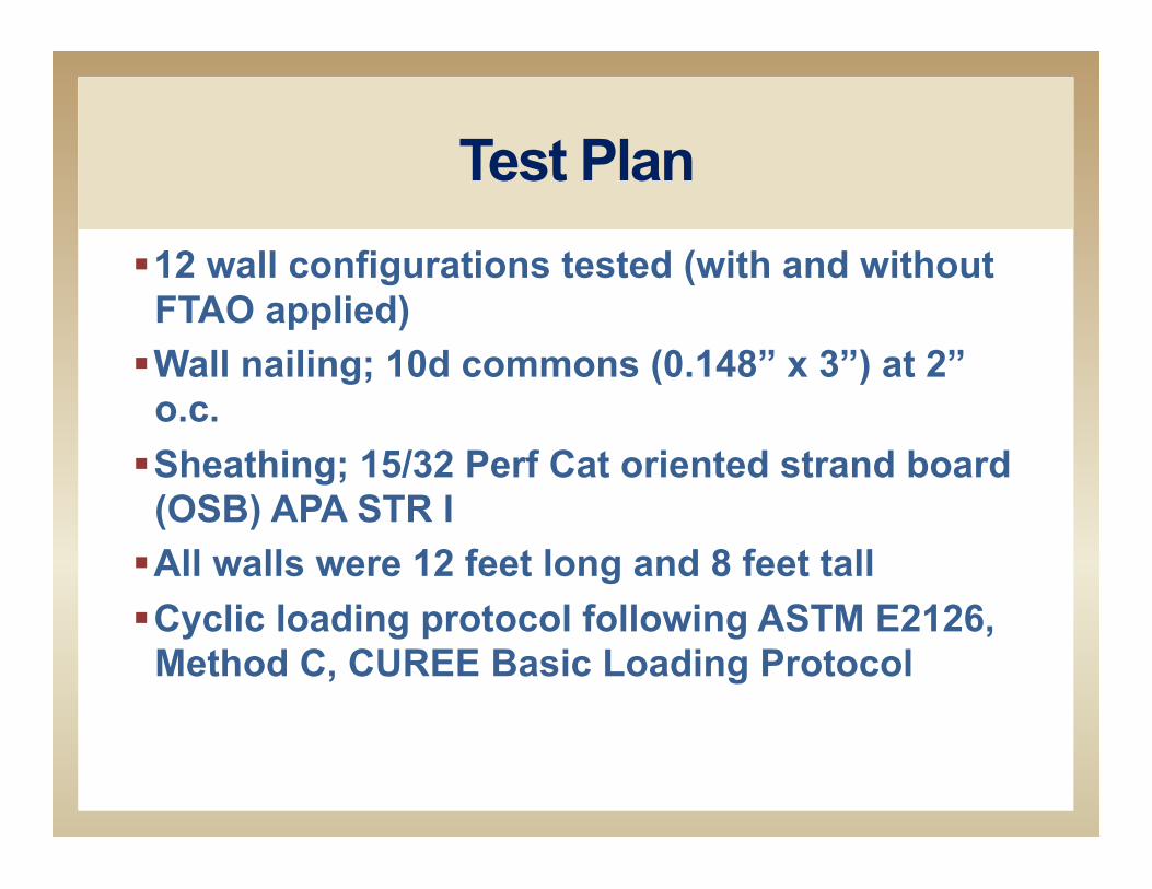
Test Plan § 12 wall configurations tested (with and without
FTAO applied) § Wall nailing; 10d commons (0.148” x 3”) at 2”
o.c. § Sheathing; 15/32 Perf Cat oriented strand board
(OSB) APA STR I § All walls were 12 feet long and 8 feet tall § Cyclic loading protocol following ASTM E2126,
Method C, CUREE Basic Loading Protocol
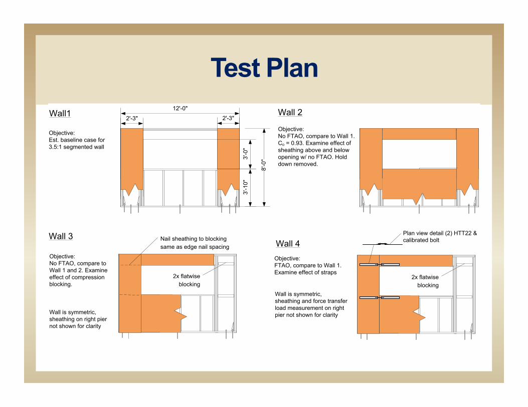
Wall 3
Objective:No FTAO, compare to Wall 1 and 2. Examine effect of compression blocking.
2x flatwise blocking
Nail sheathing to blocking same as edge nail spacing Wall 4
Objective:FTAO, compare to Wall 1. Examine effect of straps
Wall is symmetric, sheathing on right pier not shown for clarity
Wall is symmetric, sheathing and force transfer load measurement on right pier not shown for clarity
2x flatwise blocking
Plan view detail (2) HTT22 & calibrated bolt
12'-0"Wall1
Objective:Est. baseline case for 3.5:1 segmented wall
Wall 2
Objective:No FTAO, compare to Wall 1. Co = 0.93. Examine effect of sheathing above and below opening w/ no FTAO. Hold down removed.
2'-3" 2'-3"
8'-0
"3'-0
"3'
-10"
Test Plan
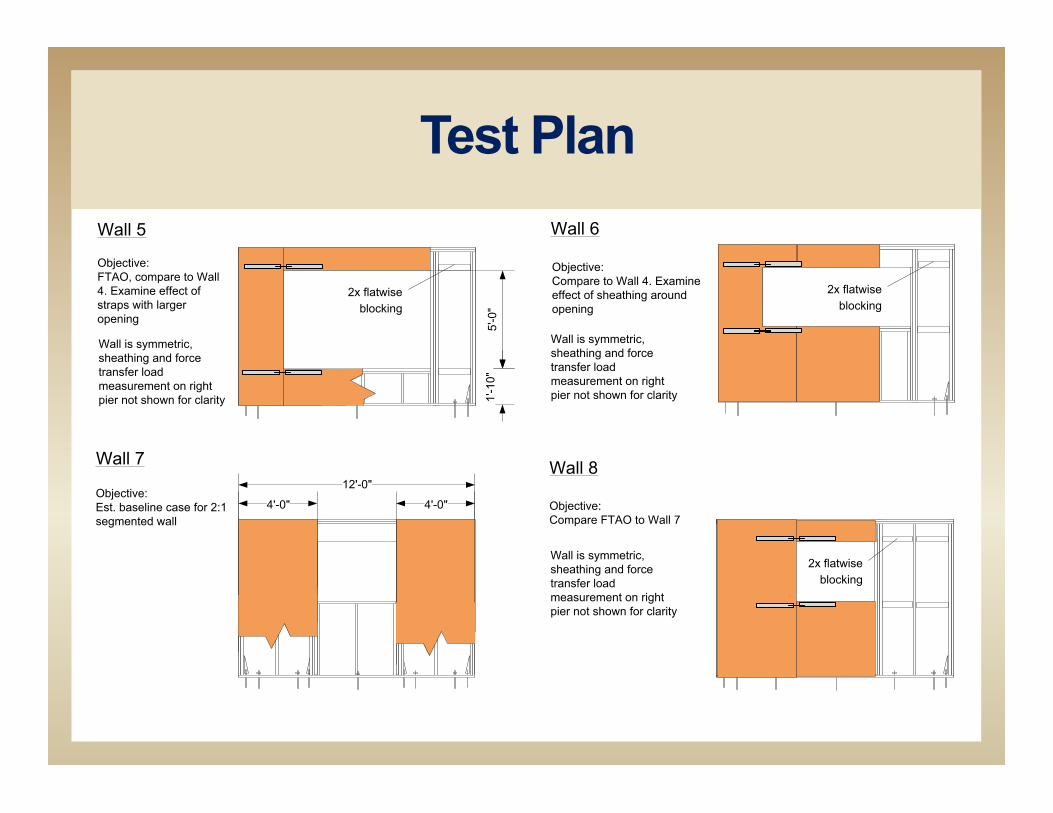
12'-0"
Wall 7
Objective:Est. baseline case for 2:1 segmented wall
4'-0" 4'-0"
Wall 8
Objective:Compare FTAO to Wall 7
Wall is symmetric, sheathing and force transfer load measurement on right pier not shown for clarity
2x flatwise blocking
Wall 5
Objective:FTAO, compare to Wall 4. Examine effect of straps with larger opening
5'-0
"
2'-0"
2x flatwise blocking
Wall is symmetric, sheathing and force transfer load measurement on right pier not shown for clarity
Wall 6
Objective:Compare to Wall 4. Examine effect of sheathing around opening
2x flatwise blocking
Wall is symmetric, sheathing and force transfer load measurement on right pier not shown for clarity1'
-10"
Test Plan
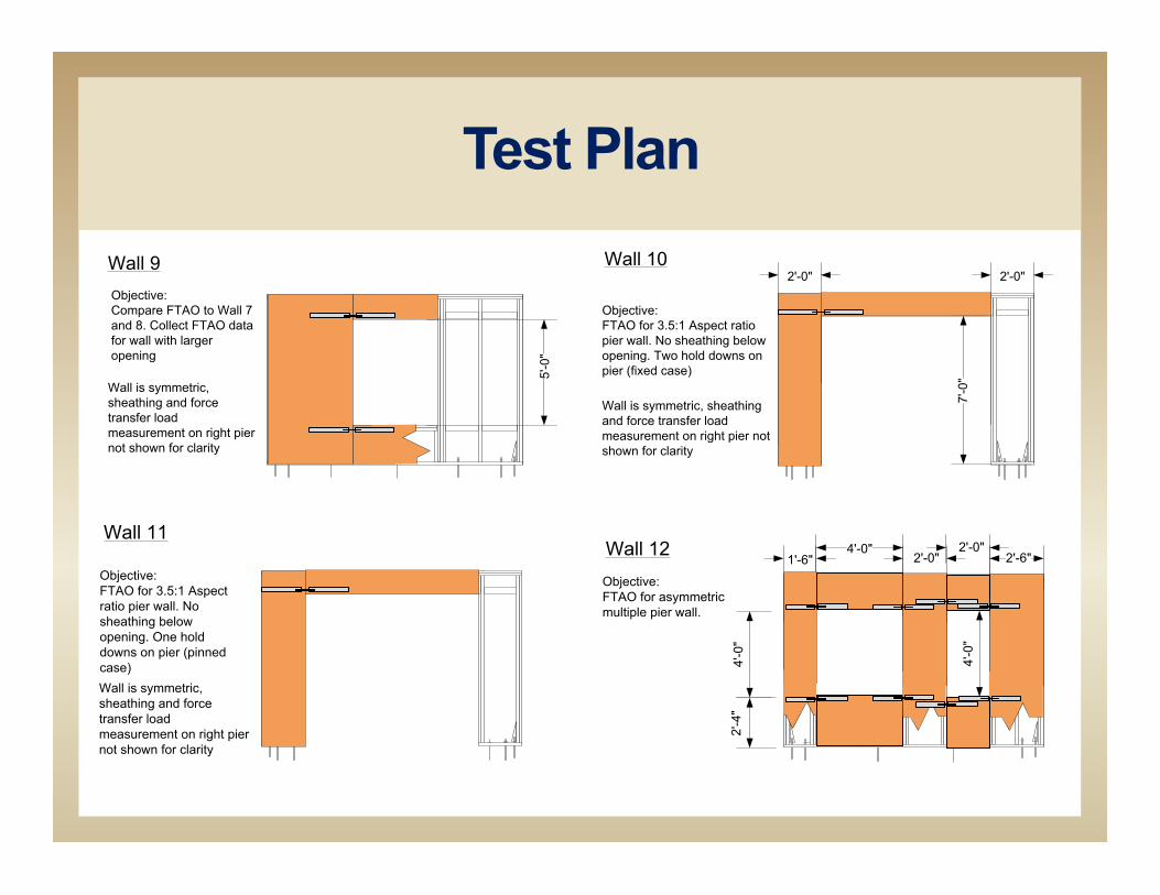
Wall 11Wall 12Objective:FTAO for asymmetric multiple pier wall.
Objective:FTAO for 3.5:1 Aspect ratio pier wall. No sheathing below opening. One hold downs on pier (pinned case)
4'-0"2'-6"2'-0"1'-6"
2'-0"
4'-0
"
Wall is symmetric, sheathing and force transfer load measurement on right pier not shown for clarity
2'-4
"4'
-0"
5'-0
"
Wall 9Objective:Compare FTAO to Wall 7 and 8. Collect FTAO data for wall with larger opening
Wall 10
Wall is symmetric, sheathing and force transfer load measurement on right pier not shown for clarity
Objective:FTAO for 3.5:1 Aspect ratio pier wall. No sheathing below opening. Two hold downs on pier (fixed case)
2'-0" 2'-0"
7'-0
"
Wall is symmetric, sheathing and force transfer load measurement on right pier not shown for clarity
Test Plan
Test Plan Information obtained
§ Cyclic hysteretic plots and various cyclic parameters of the individual walls
§ Hold down force plots § Anchor bolt forces plots § Hysteric plots of the applied load versus the displacement
of the walls § Hysteric plots of the applied load versus strap forces

CUREE Basic Loading Protocol
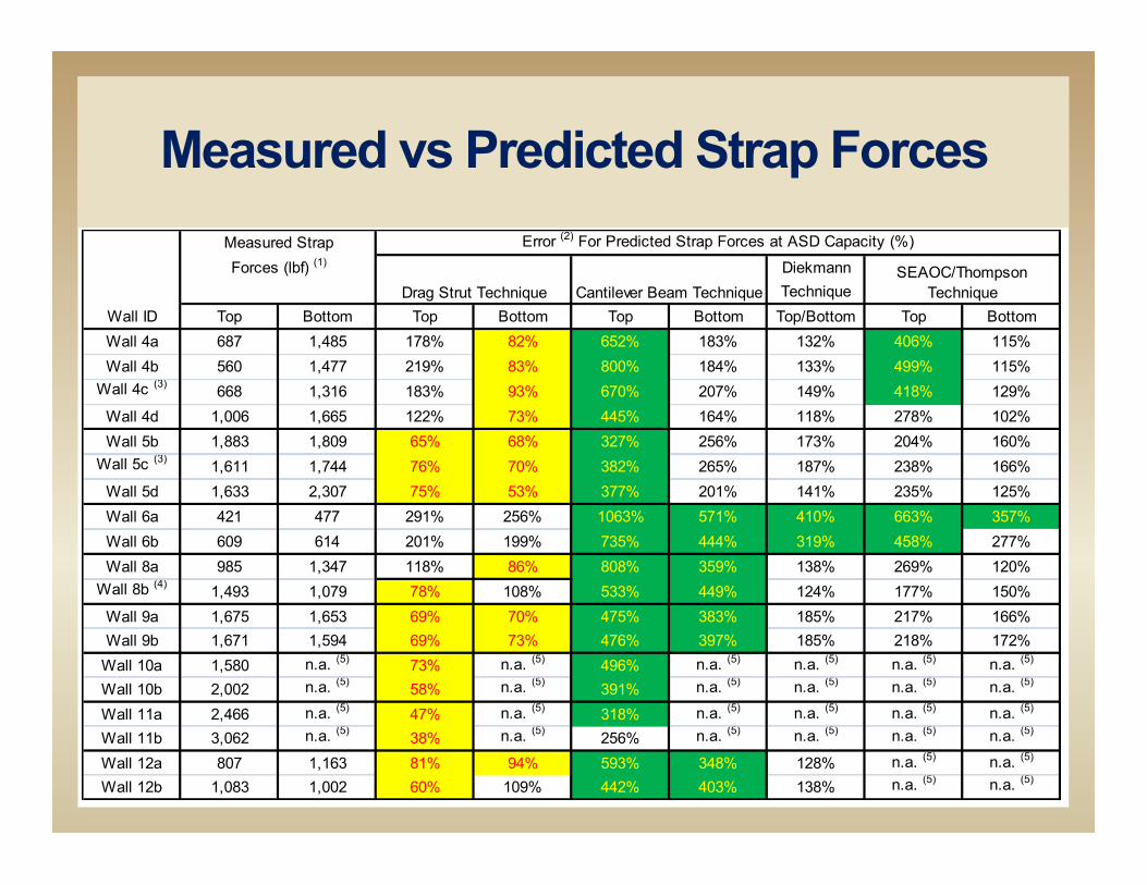
Measured vs Predicted Strap Forces
DiekmannTechnique
Top Bottom Top Bottom Top Bottom Top/Bottom Top BottomWall 4a 687 1,485 178% 82% 652% 183% 132% 406% 115%Wall 4b 560 1,477 219% 83% 800% 184% 133% 499% 115%
Wall 4c (3) 668 1,316 183% 93% 670% 207% 149% 418% 129%Wall 4d 1,006 1,665 122% 73% 445% 164% 118% 278% 102%Wall 5b 1,883 1,809 65% 68% 327% 256% 173% 204% 160%
Wall 5c (3) 1,611 1,744 76% 70% 382% 265% 187% 238% 166%Wall 5d 1,633 2,307 75% 53% 377% 201% 141% 235% 125%Wall 6a 421 477 291% 256% 1063% 571% 410% 663% 357%Wall 6b 609 614 201% 199% 735% 444% 319% 458% 277%Wall 8a 985 1,347 118% 86% 808% 359% 138% 269% 120%
Wall 8b (4) 1,493 1,079 78% 108% 533% 449% 124% 177% 150%Wall 9a 1,675 1,653 69% 70% 475% 383% 185% 217% 166%Wall 9b 1,671 1,594 69% 73% 476% 397% 185% 218% 172%
Wall 10a 1,580 n.a. (5) 73% n.a. (5) 496% n.a. (5) n.a. (5) n.a. (5) n.a. (5)
Wall 10b 2,002 n.a. (5) 58% n.a. (5) 391% n.a. (5) n.a. (5) n.a. (5) n.a. (5)
Wall 11a 2,466 n.a. (5) 47% n.a. (5) 318% n.a. (5) n.a. (5) n.a. (5) n.a. (5)
Wall 11b 3,062 n.a. (5) 38% n.a. (5) 256% n.a. (5) n.a. (5) n.a. (5) n.a. (5)
Wall 12a 807 1,163 81% 94% 593% 348% 128% n.a. (5) n.a. (5)
Wall 12b 1,083 1,002 60% 109% 442% 403% 138% n.a. (5) n.a. (5)
Error (2) For Predicted Strap Forces at ASD Capacity (%)
Wall ID
Measured StrapForces (lbf) (1)
Drag Strut Technique Cantilever Beam TechniqueSEAOC/Thompson
Technique
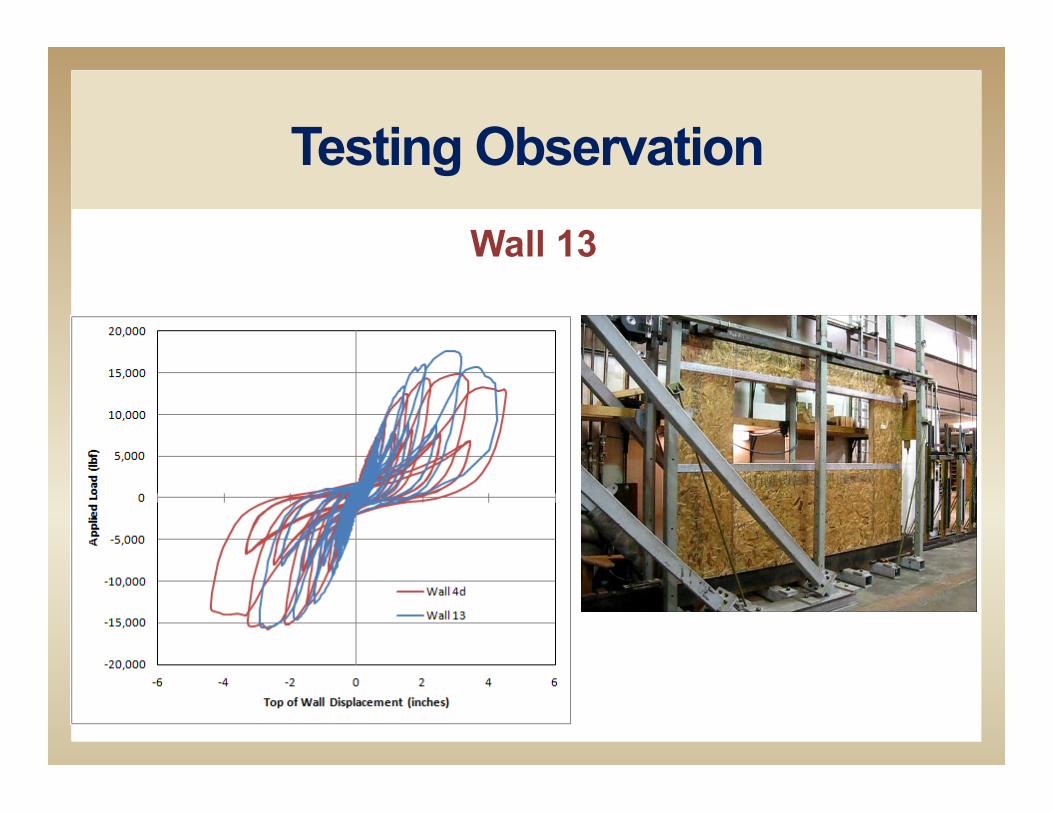
Testing Observation Wall 13
Click to Play
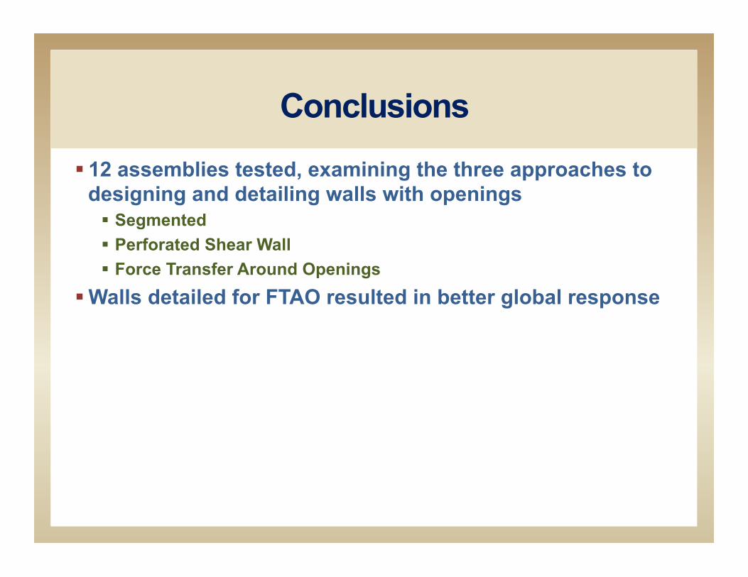
Conclusions § 12 assemblies tested, examining the three approaches to
designing and detailing walls with openings § Segmented § Perforated Shear Wall § Force Transfer Around Openings
§ Walls detailed for FTAO resulted in better global response
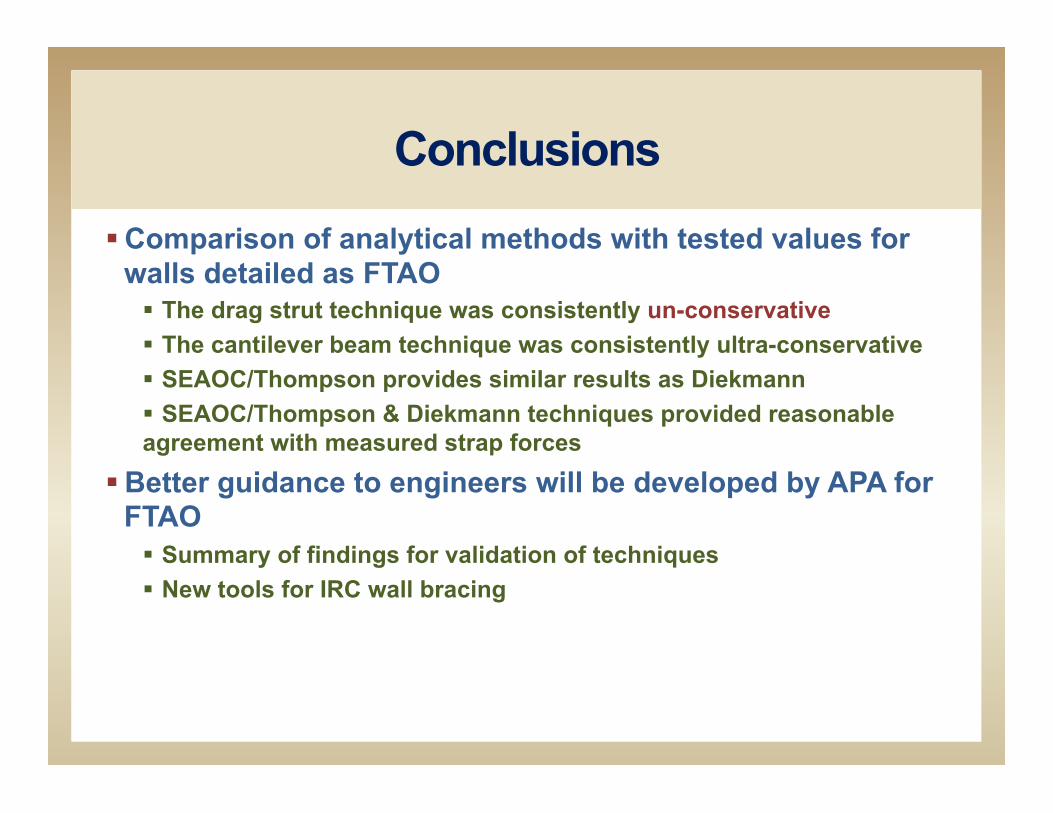
Conclusions § Comparison of analytical methods with tested values for
walls detailed as FTAO § The drag strut technique was consistently un-conservative § The cantilever beam technique was consistently ultra-conservative § SEAOC/Thompson provides similar results as Diekmann § SEAOC/Thompson & Diekmann techniques provided reasonable agreement with measured strap forces
§ Better guidance to engineers will be developed by APA for FTAO § Summary of findings for validation of techniques § New tools for IRC wall bracing

Report Available
§ www.apawood.org/publications § Report is 149 pages, 28.5 MB
Enter: “force transfer” or “M410”
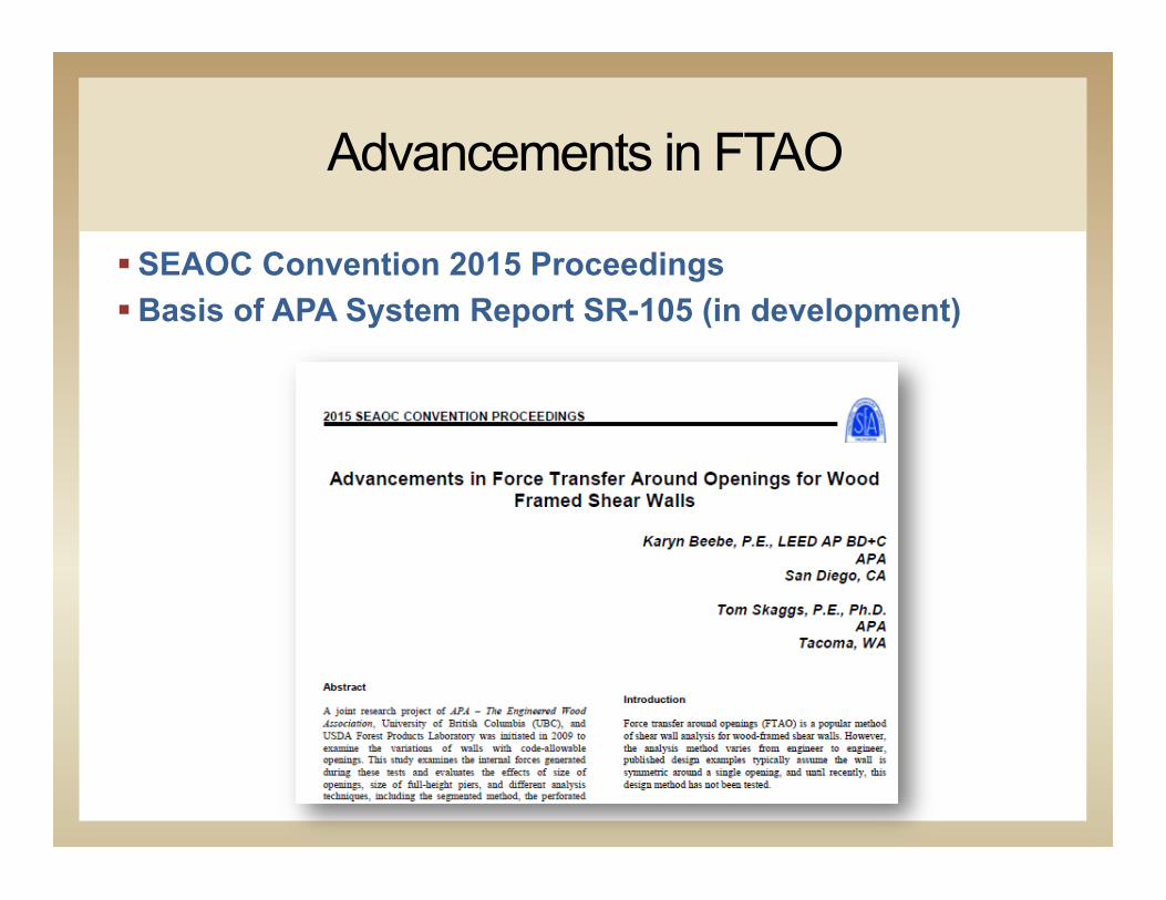
Advancements in FTAO
§ SEAOC Convention 2015 Proceedings § Basis of APA System Report SR-105 (in development)
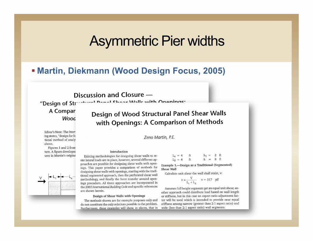
Asymmetric Pier widths
§ Martin, Diekmann (Wood Design Focus, 2005)

Multiple Openings
§ APA FTAO Testing Wall 12 § Multiple openings § Asymmetric pier widths
§ Diekmann Rational Analysis
Wall 11
Wall 12Objective:FTAO for asymmetric multiple pier wall.
Objective:FTAO for 3.5:1 Aspect ratio pier wall. No sheathing below opening. One hold downs on pier (pinned case)
4'-0"2'-6"2'-0"1'-6"
2'-0"
4'-0
"
Wall is symmetric, sheathing and force transfer load measurement on right pier not shown for clarity
2'-4
"4'
-0"

Conceptual Keys
The method assumes the following: § The unit shear above and below the openings is
equivalent. § The corner forces are based on the shear above and below
the openings and only the piers adjacent to that unique opening.
§ The tributary length of the opening is the basis for calculating the shear to each pier. This tributary length is the ratio of the length of the pier multiplied by the length of the opening it is adjacent to, then divided by the sum of the length of the pier and the length of the pier on the other side of the opening. § For example, T1 = (L1*Lo1)/(L1+L2)
Conceptual Keys
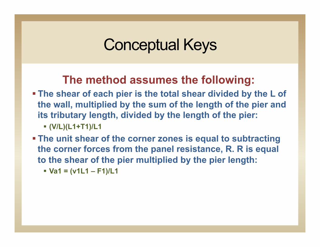
The method assumes the following: § The shear of each pier is the total shear divided by the L of
the wall, multiplied by the sum of the length of the pier and its tributary length, divided by the length of the pier: § (V/L)(L1+T1)/L1
§ The unit shear of the corner zones is equal to subtracting the corner forces from the panel resistance, R. R is equal to the shear of the pier multiplied by the pier length: § Va1 = (v1L1 – F1)/L1
Conceptual Keys
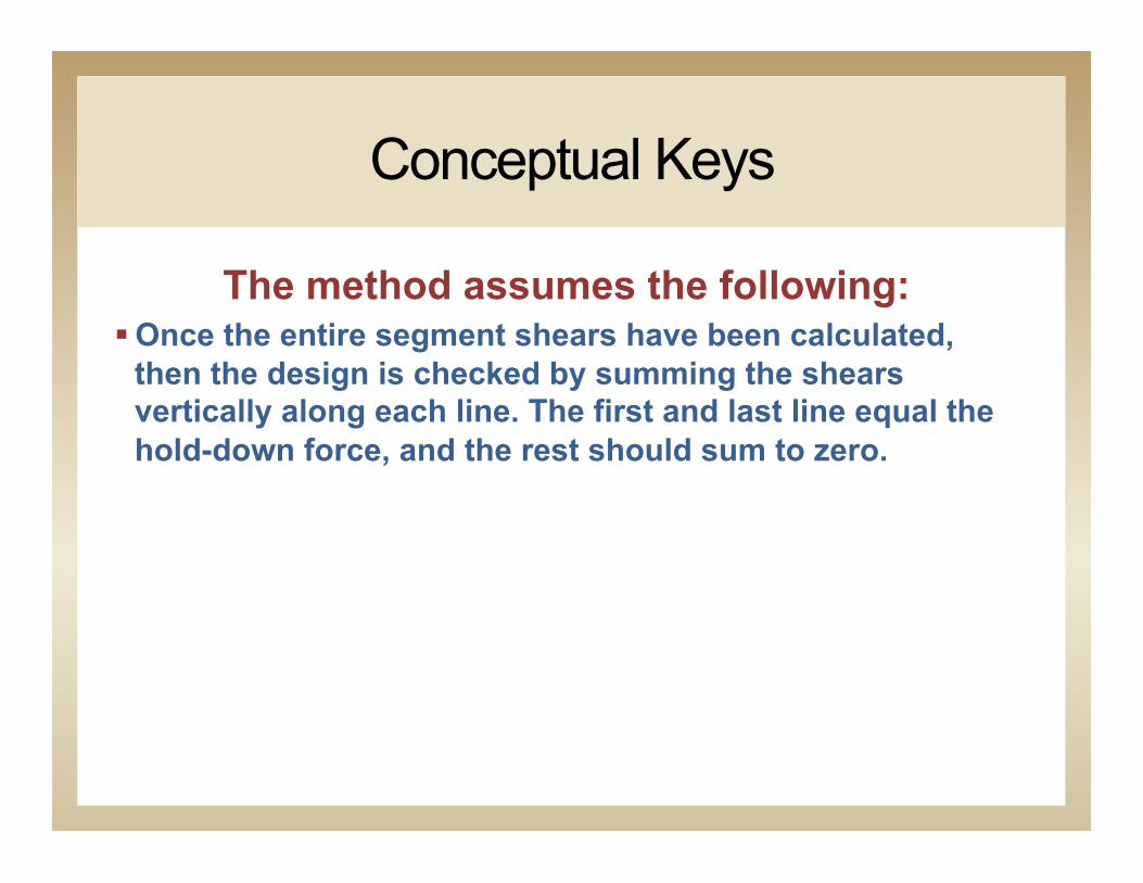
The method assumes the following: § Once the entire segment shears have been calculated,
then the design is checked by summing the shears vertically along each line. The first and last line equal the hold-down force, and the rest should sum to zero.
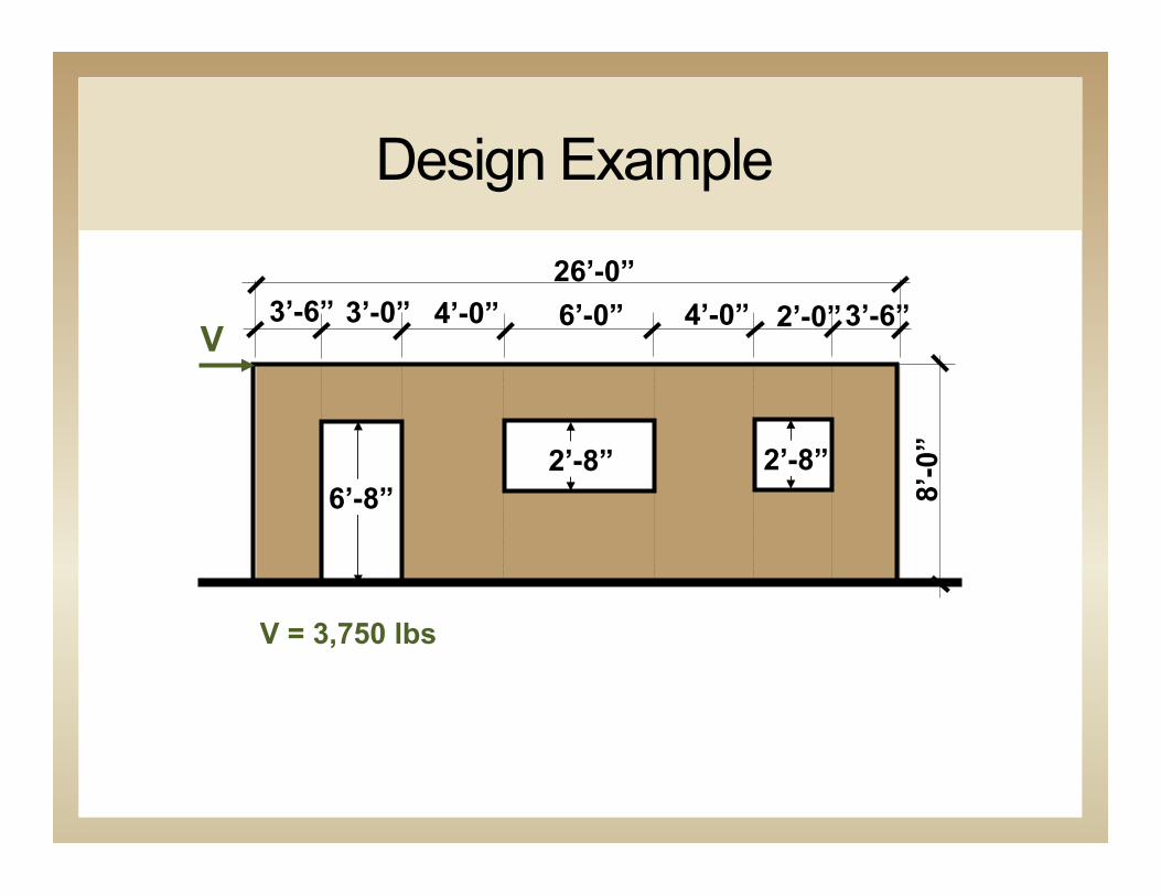
Design Example
3’-6” 3’-0” 4’-0” 6’-0” 4’-0” 3’-6” 2’-0”
6’-8” 2’-8” 2’-8”
8’-0
”
V
V = 3,750 lbs
26’-0”
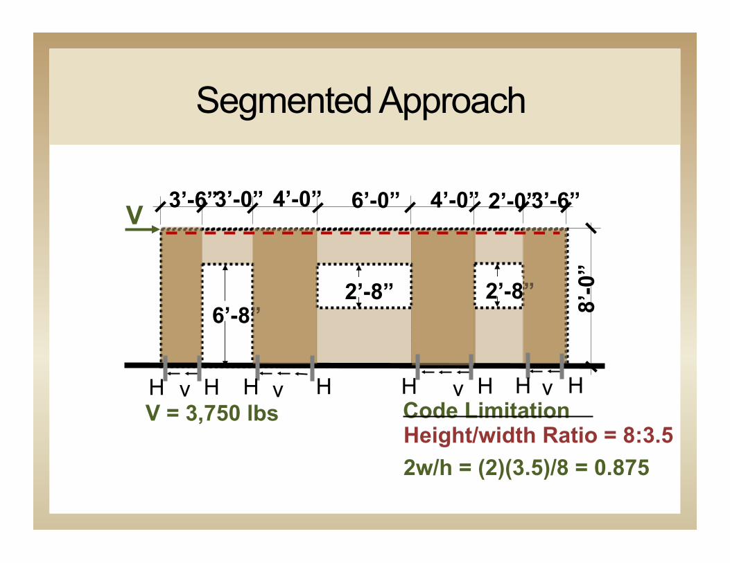
Segmented Approach
4’-0” 6’-0” 4’-0” 3’-6” 2’-0”
6’-8” 2’-8” 2’-8” 8’
-0”
V
V = 3,750 lbs Height/width Ratio = 8:3.5 2w/h = (2)(3.5)/8 = 0.875
v v v v H H H H H H H H Code Limitation
3’-6” 3’-0”
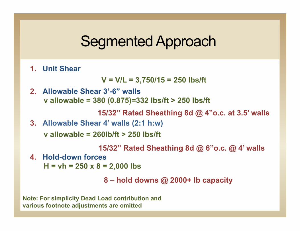
Segmented Approach 1. Unit Shear
V = V/L = 3,750/15 = 250 lbs/ft 2. Allowable Shear 3’-6” walls
v allowable = 380 (0.875)=332 lbs/ft > 250 lbs/ft
3. Allowable Shear 4’ walls (2:1 h:w) v allowable = 260lb/ft > 250 lbs/ft
4. Hold-down forces H = vh = 250 x 8 = 2,000 lbs
15/32” Rated Sheathing 8d @ 4”o.c. at 3.5’ walls
Note: For simplicity Dead Load contribution and various footnote adjustments are omitted
8 – hold downs @ 2000+ lb capacity
15/32” Rated Sheathing 8d @ 6”o.c. @ 4’ walls
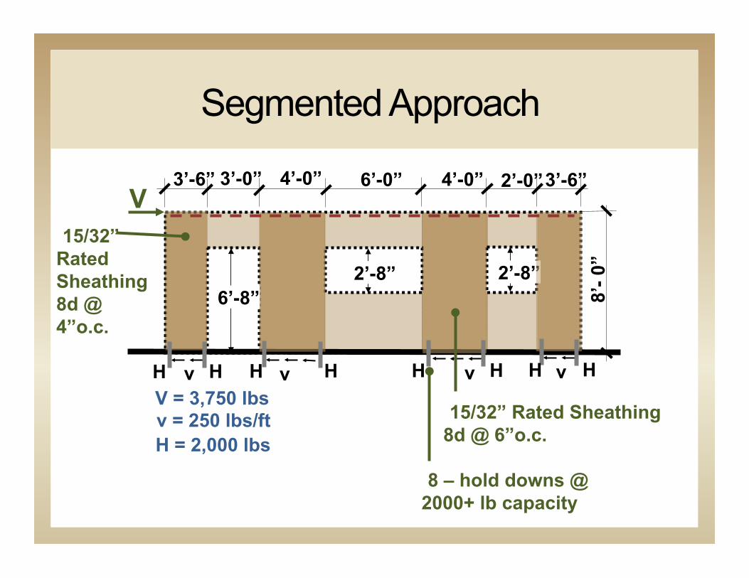
Segmented Approach
8 – hold downs @ 2000+ lb capacity
4’-0” 6’-0” 4’-0” 3’-6” 2’-0”
6’-8” 2’-8” 2’-8”
8’- 0
”
V
V = 3,750 lbs v = 250 lbs/ft H = 2,000 lbs
v v v v H H H H H H H H
3’-6” 3’-0”
15/32” Rated Sheathing 8d @ 6”o.c.
15/32” Rated Sheathing 8d @ 4”o.c.
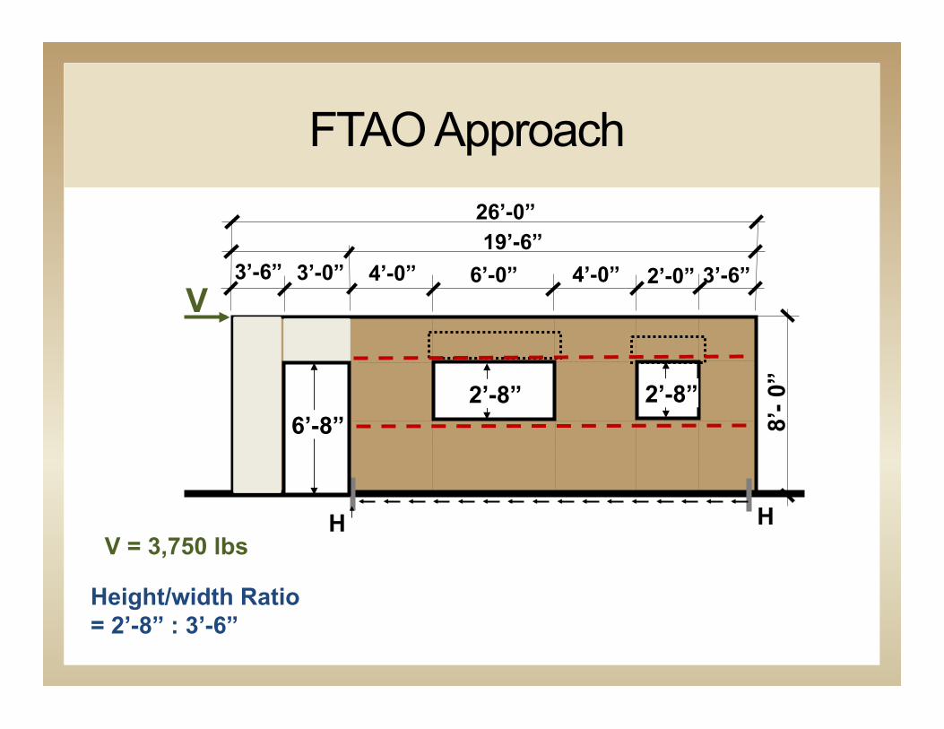
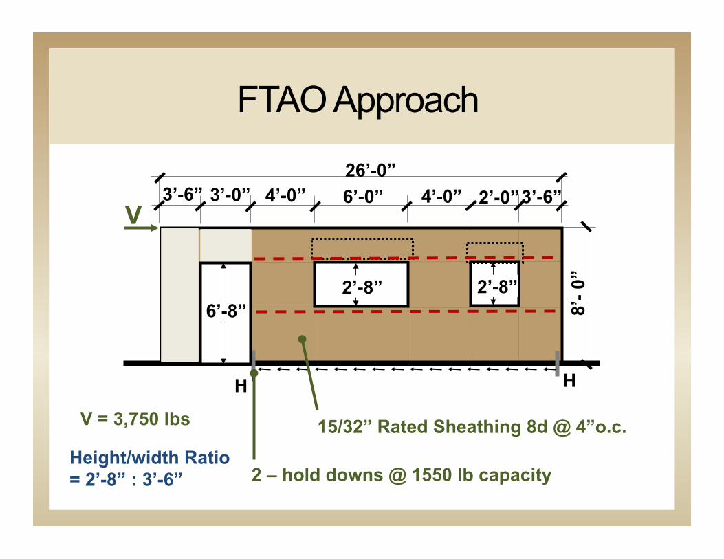
FTAO Approach
3’-6” 3’-0” 4’-0” 6’-0” 4’-0” 3’-6” 2’-0”
2’-8” 2’-8”
8’- 0
”
V
V = 3,750 lbs H H
26’-0”
Height/width Ratio = 2’-8” : 3’-6”
6’-8”
19’-6”
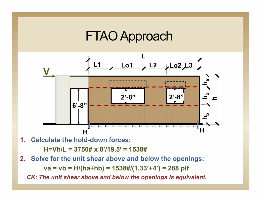
FTAO Approach
L1 Lo1 L2 L3 Lo2
2’-8” 2’-8”
V
H H
L
6’-8”
h h o
h a
h b
1. Calculate the hold-down forces: H=Vh/L = 3750# x 8’/19.5’ = 1538#
2. Solve for the unit shear above and below the openings: va = vb = H/(ha+hb) = 1538#/(1.33’+4’) = 288 plf
CK: The unit shear above and below the openings is equivalent.
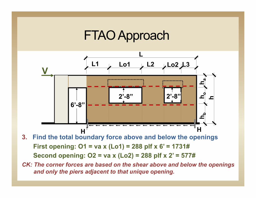
FTAO Approach
L1 Lo1 L2 L3 Lo2
2’-8” 2’-8”
V
H H
L
6’-8”
h h o
h a
h b
3. Find the total boundary force above and below the openings First opening: O1 = va x (Lo1) = 288 plf x 6’ = 1731# Second opening: O2 = va x (Lo2) = 288 plf x 2’ = 577#
CK: The corner forces are based on the shear above and below the openings and only the piers adjacent to that unique opening.

FTAO Approach
L1 Lo1 L2 L3 Lo2
2’-8” 2’-8”
V
H H
L
6’-8”
h h o
h a
h b
4. Calculate the corner forces: F1 = O1(L1)/(L1+L2) = 865# F2 = O1(L2)/(L1+L2) = 865# F3 = O2(L2)/(L2+L3) = 308# F4 = O2(L3)/(L2+L3) = 269#
CK: Strap forces
F1 F2 F3 F4
F1 F2 F3 F4
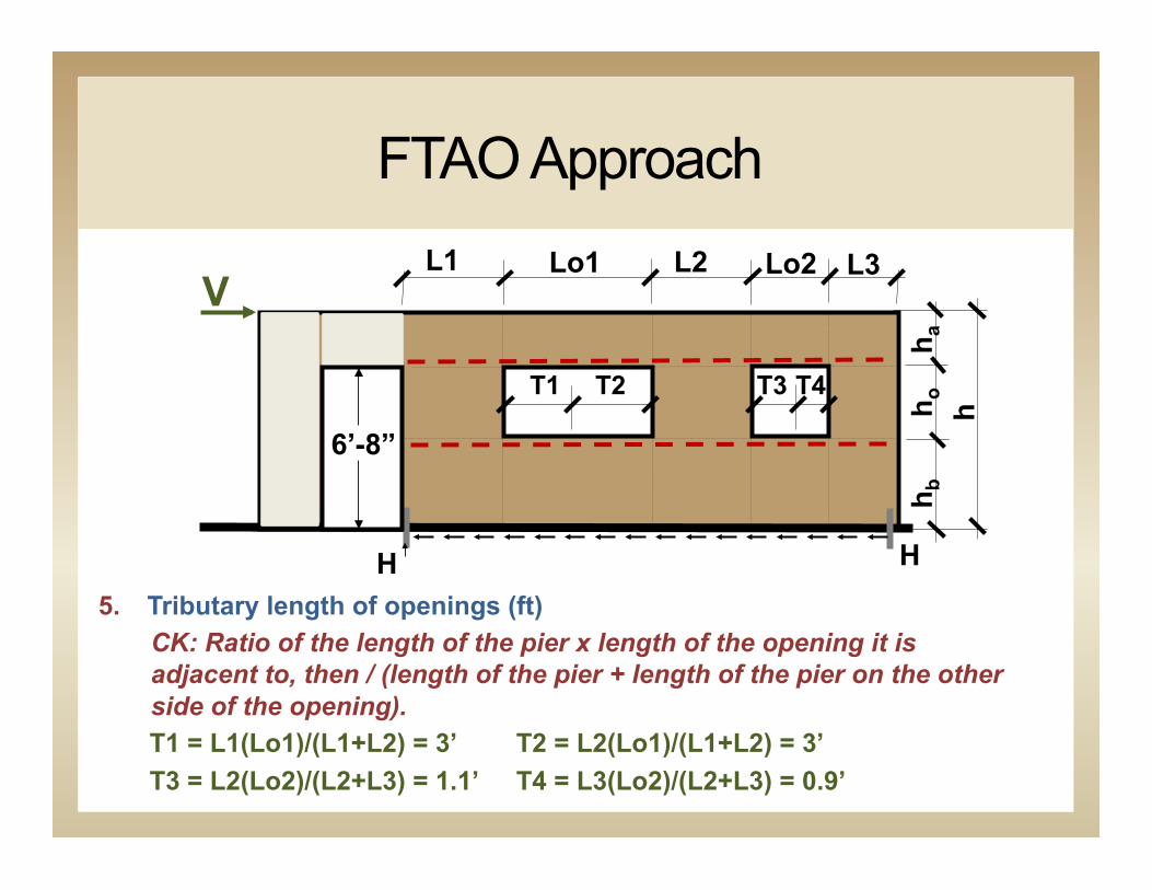
FTAO Approach L1 Lo1 L2 L3 Lo2
V
H H
6’-8”
h h o
h a
h b
5. Tributary length of openings (ft) CK: Ratio of the length of the pier x length of the opening it is adjacent to, then / (length of the pier + length of the pier on the other side of the opening).
T1 = L1(Lo1)/(L1+L2) = 3’ T2 = L2(Lo1)/(L1+L2) = 3’ T3 = L2(Lo2)/(L2+L3) = 1.1’ T4 = L3(Lo2)/(L2+L3) = 0.9’
T1 T2 T3 T4
FTAO Approach
L1 Lo1 L2 L3 Lo2 V
H H
L
6’-8”
h h o
h a
h b
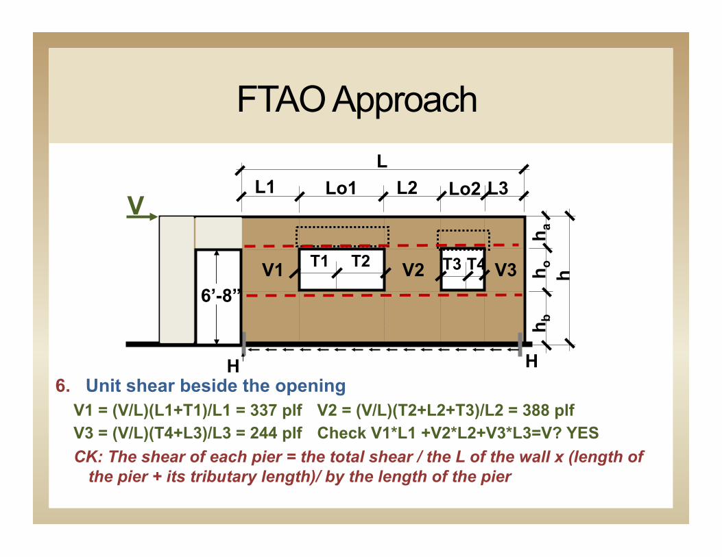
6. Unit shear beside the opening V1 = (V/L)(L1+T1)/L1 = 337 plf V2 = (V/L)(T2+L2+T3)/L2 = 388 plf V3 = (V/L)(T4+L3)/L3 = 244 plf Check V1*L1 +V2*L2+V3*L3=V? YES CK: The shear of each pier = the total shear / the L of the wall x (length of
the pier + its tributary length)/ by the length of the pier
T1 T2 T3 T4 V1 V2 V3
FTAO Approach
L1 Lo1 L2 L3 Lo2
2’-8” 2’-8”
V
H H
L
6’-8”
h h o
h a
h b
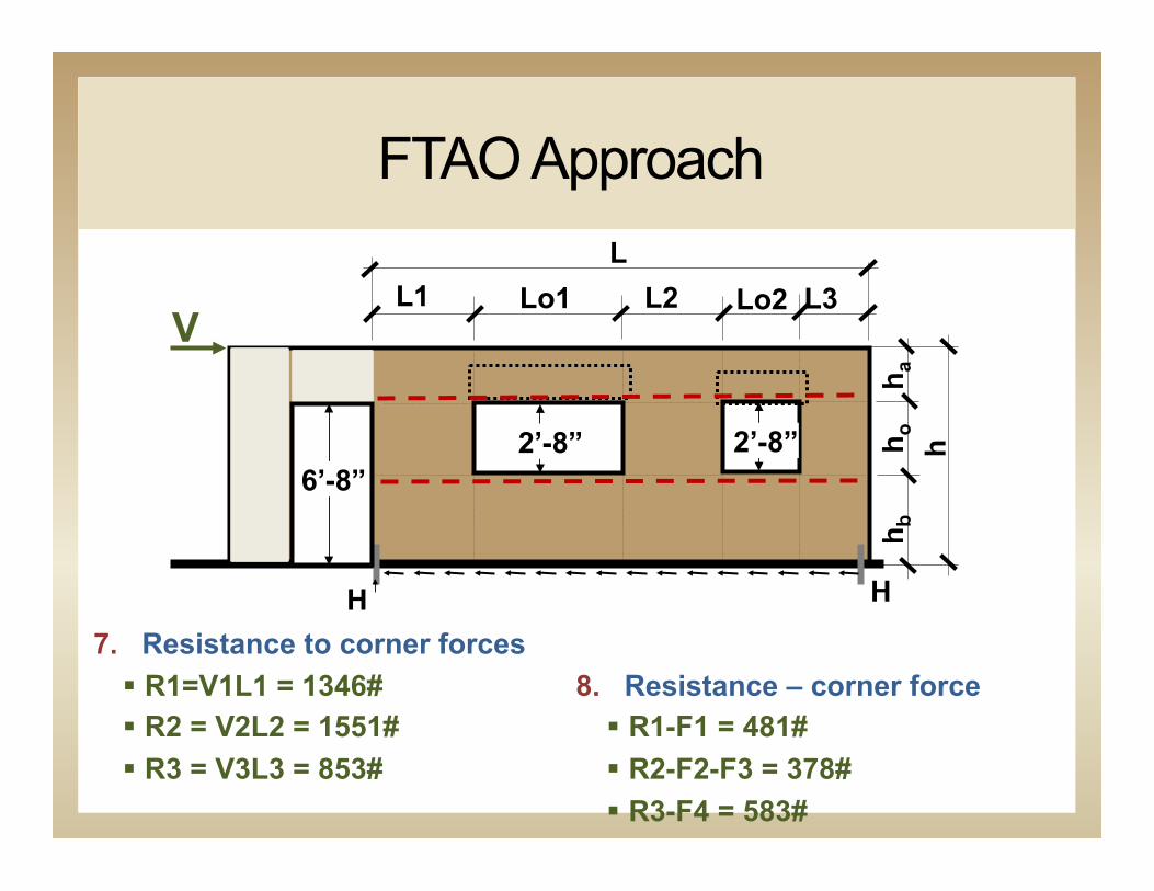
7. Resistance to corner forces § R1=V1L1 = 1346# § R2 = V2L2 = 1551# § R3 = V3L3 = 853#
8. Resistance – corner force § R1-F1 = 481# § R2-F2-F3 = 378# § R3-F4 = 583#
FTAO Approach
L1 Lo1 L2 L3 Lo2
2’-8” 2’-8”
V
H H
L
6’-8”
h h o
h a
h b
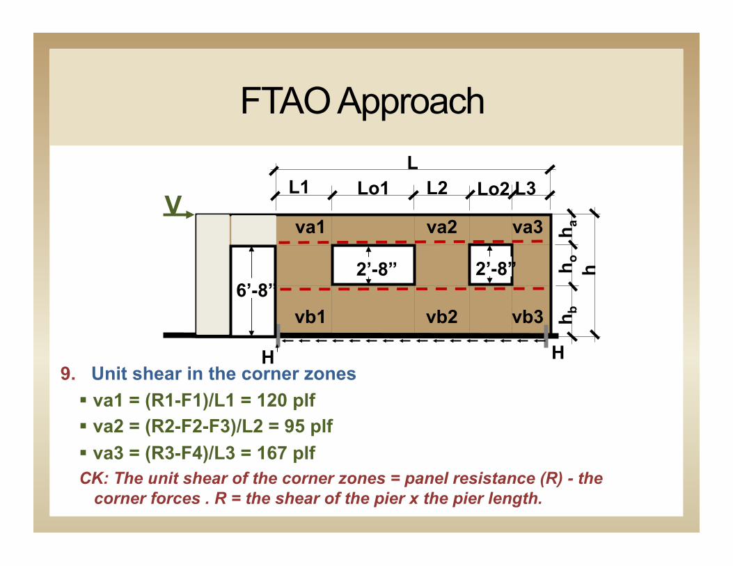
9. Unit shear in the corner zones § va1 = (R1-F1)/L1 = 120 plf § va2 = (R2-F2-F3)/L2 = 95 plf § va3 = (R3-F4)/L3 = 167 plf CK: The unit shear of the corner zones = panel resistance (R) - the
corner forces . R = the shear of the pier x the pier length.
va1 va2
vb1 vb2
va3
vb3
FTAO Approach
L1 Lo1 L2 L3 Lo2
2’-8” 2’-8”
V
H H
6’-8”
h h o
h a
h b
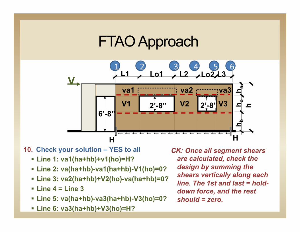
10. Check your solution – YES to all § Line 1: va1(ha+hb)+v1(ho)=H? § Line 2: va(ha+hb)-va1(ha+hb)-V1(ho)=0? § Line 3: va2(ha+hb)+V2(ho)-va(ha+hb)=0? § Line 4 = Line 3 § Line 5: va(ha+hb)-va3(ha+hb)-V3(ho)=0? § Line 6: va3(ha+hb)+V3(ho)=H?
1 2 43 5 6
CK: Once all segment shears are calculated, check the design by summing the shears vertically along each line. The 1st and last = hold-down force, and the rest should = zero.
va1 va2 va3
V1 V2 V3
FTAO Approach
3’-6” 3’-0” 4’-0” 6’-0” 4’-0” 3’-6” 2’-0”
2’-8” 2’-8”
8’- 0
”
V
V = 3,750 lbs
H H
26’-0”
Height/width Ratio = 2’-8” : 3’-6”
6’-8”
15/32” Rated Sheathing 8d @ 4”o.c.
2 – hold downs @ 1550 lb capacity
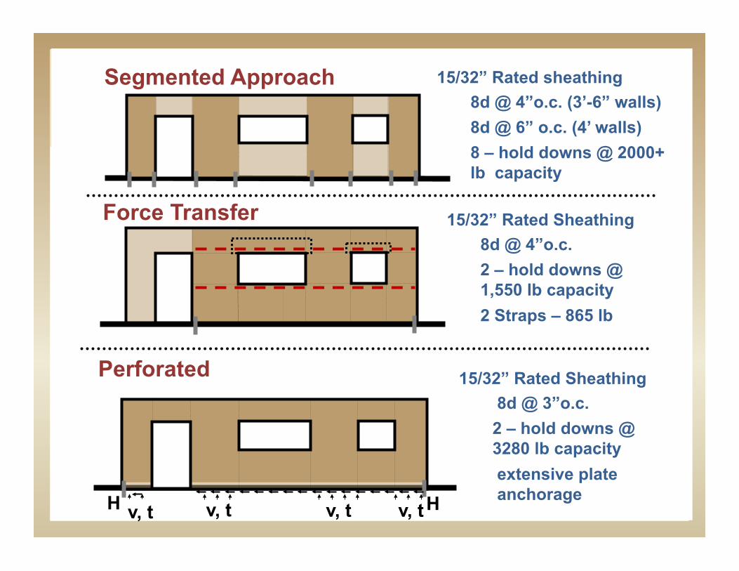
15/32” Rated sheathing 8d @ 4”o.c. (3’-6” walls) 8d @ 6” o.c. (4’ walls) 8 – hold downs @ 2000+ lb capacity
Segmented Approach
15/32” Rated Sheathing 8d @ 4”o.c. 2 – hold downs @ 1,550 lb capacity 2 Straps – 865 lb
Force Transfer
v, t H H v, t v, t
15/32” Rated Sheathing 8d @ 3”o.c. 2 – hold downs @ 3280 lb capacity extensive plate anchorage
Perforated
v, t

C-shaped Panels
§ APA FTAO Test Wall 6 § Framing status quo § Reduce/eliminate
strap force
Wall 5
Objective:FTAO, compare to Wall 4. Examine effect of straps with larger opening
5'-0
"
2'-0"
2x flatwise blocking
Wall is symmetric, sheathing and force transfer load measurement on right pier not shown for clarity
Wall 6
Objective:Compare to Wall 4. Examine effect of sheathing around opening
2x flatwise blocking
Wall is symmetric, sheathing and force transfer load measurement on right pier not shown for clarity1'
-10"

Deflection Calculations - Concept
V+
H H
h 2+
h 1+
h 3+
δ1+ δ2
+ δ3+
V-
H H h 2
-
h 1- h 3
-
δ1- δ2
- δ3-
Δ = average(δ1+, δ2
+ ,δ3+,
δ1-, δ2
-, δ3-)
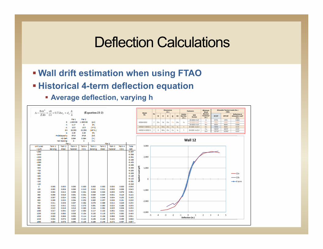
Deflection Calculations
§ Wall drift estimation when using FTAO § Historical 4-term deflection equation
§ Average deflection, varying h
-‐3,000
-‐2,000
-‐1,000
0
1,000
2,000
3,000
-‐5 -‐4 -‐3 -‐2 -‐1 0 1 2 3 4 5
Applied Load
(plf)
Deflection (in.)
Wall 12
12a
12b
4 term

Benefits of FTAO with Continuous WSPs
For the Structural Engineer… § Straightforward rational analysis § Easy to program: Excel, web based application, or other § Design check = confidence in calculations

Benefits of FTAO with Continuous WSPs
Architectural flexibility § Definition of aspect ratio § Building envelope
§ Uninterrupted drainage plane § Minimize water intrusion
Four D's of Design
3. Drying
4. Durable
1. Deflection
2. Drainage

Benefits of FTAO with Continuous WSPs
§ High Performance Wall Systems § 2x6 Advanced Framing § Insulated headers
and corners
Min R10.7 header
R19 batts (=R18) Min 7/16 CAT WSP
R4 (1” EPS) WRB
1-coat stucco
Structural Systems that Enhance Energy Efficiency

Benefits of FTAO with Continuous WSPs
Air Infiltration = Energy Loss § Air barrier should be continuous § Joints need to be sealed (i.e. blocked panel edges) § Need water resistive barrier
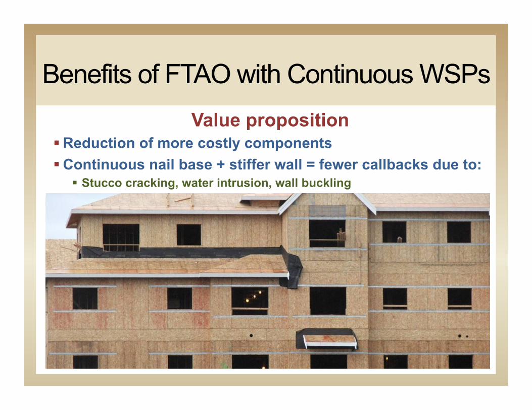
Benefits of FTAO with Continuous WSPs Value proposition
§ Reduction of more costly components § Continuous nail base + stiffer wall = fewer callbacks due to:
§ Stucco cracking, water intrusion, wall buckling

Questions/ Comments?
Karyn A. Beebe, P.E., LEED AP [email protected] (858) 668-7161 www.apawood.org
• This concludes The American Ins<tute of Architects Con<nuing Educa<on Systems Course