Embed Size (px)
Citation preview
Advanced Design System 2002
IFF Translation for Mentor Graphics
February 2002
Notice
The information contained in this document is subject to change without notice.
Agilent Technologies makes no warranty of any kind with regard to this material,including, but not limited to, the implied warranties of merchantability and fitnessfor a particular purpose. Agilent Technologies shall not be liable for errors containedherein or for incidental or consequential damages in connection with the furnishing,performance, or use of this material.
Warranty
A copy of the specific warranty terms that apply to this software product is availableupon request from your Agilent Technologies representative.
Restricted Rights Legend
Use, duplication or disclosure by the U. S. Government is subject to restrictions as setforth in subparagraph (c) (1) (ii) of the Rights in Technical Data and ComputerSoftware clause at DFARS 252.227-7013 for DoD agencies, and subparagraphs (c) (1)and (c) (2) of the Commercial Computer Software Restricted Rights clause at FAR52.227-19 for other agencies.
Agilent Technologies395 Page Mill RoadPalo Alto, CA 94304 U.S.A.
Copyright © 2002, Agilent Technologies. All Rights Reserved.
Acknowledgments
Mentor Graphics®, Boardstation® and Design Architect® are registered trademarksof Mentor Graphics Incorporated.
Copyright © 1997-2001 Mentor Graphics Incorporated. All rights reserved.
ii
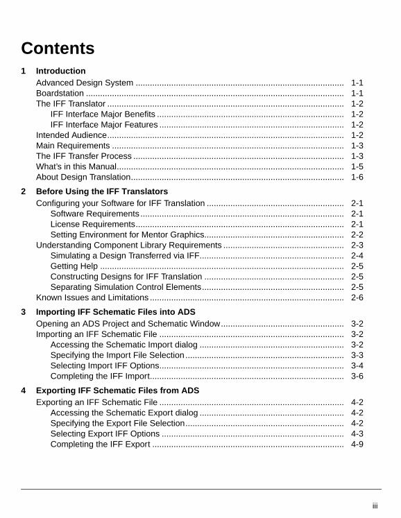
Contents1 Introduction
Advanced Design System ........................................................................................ 1-1Boardstation ............................................................................................................. 1-1The IFF Translator .................................................................................................... 1-2
IFF Interface Major Benefits ............................................................................... 1-2IFF Interface Major Features .............................................................................. 1-2
Intended Audience.................................................................................................... 1-2Main Requirements .................................................................................................. 1-3The IFF Transfer Process ......................................................................................... 1-3What’s in this Manual................................................................................................ 1-5About Design Translation.......................................................................................... 1-6
2 Before Using the IFF TranslatorsConfiguring your Software for IFF Translation .......................................................... 2-1
Software Requirements ...................................................................................... 2-1License Requirements........................................................................................ 2-1Setting Environment for Mentor Graphics........................................................... 2-2
Understanding Component Library Requirements ................................................... 2-3Simulating a Design Transferred via IFF............................................................. 2-4Getting Help ....................................................................................................... 2-5Constructing Designs for IFF Translation ........................................................... 2-5Separating Simulation Control Elements............................................................ 2-5
Known Issues and Limitations .................................................................................. 2-6
3 Importing IFF Schematic Files into ADSOpening an ADS Project and Schematic Window.................................................... 3-2Importing an IFF Schematic File .............................................................................. 3-2
Accessing the Schematic Import dialog ............................................................. 3-2Specifying the Import File Selection ................................................................... 3-3Selecting Import IFF Options.............................................................................. 3-4Completing the IFF Import.................................................................................. 3-6
4 Exporting IFF Schematic Files from ADSExporting an IFF Schematic File .............................................................................. 4-2
Accessing the Schematic Export dialog ............................................................. 4-2Specifying the Export File Selection................................................................... 4-2Selecting Export IFF Options ............................................................................. 4-3Completing the IFF Export ................................................................................. 4-9
iii
5 Importing IFF Files into Mentor GraphicsImporting an IFF Schematic File .............................................................................. 5-2
Accessing the Framework Input Transfer Form .................................................. 5-2Specifying the File Name and Setting Import Options........................................ 5-4Completing the Import ........................................................................................ 5-5Setting Up a Library Search Path ....................................................................... 5-5
Importing an IFF Layout File..................................................................................... 5-6Completing the Layout Import ............................................................................ 5-6
6 Exporting Designs to IFF from BoardstationExporting an IFF Schematic File .............................................................................. 6-1
Accessing the IFF Write Dialog in Design Architect ........................................... 6-2Completing the Export........................................................................................ 6-4
Exporting an IFF Layout File .................................................................................... 6-4Accessing the IFF Write Dialog in RF Layout ........................................................... 6-5
Completing the IFF Export ................................................................................. 6-6
7 Importing IFF Layout Files into ADSOpening an ADS Project and Layout Window .......................................................... 7-2Importing an IFF Layout File..................................................................................... 7-2
Accessing the Layout Import dialog.................................................................... 7-2Specifying the Import File Selection ................................................................... 7-3Selecting Import IFF Options.............................................................................. 7-4Completing the IFF Import.................................................................................. 7-7
8 Exporting IFF Layout Files from ADSExporting an IFF Layout File .................................................................................... 8-2
Accessing the MGC/PCB Export dialog ............................................................. 8-2Where do the files go? ....................................................................................... 8-2Selecting MGC/PCB Export Options .................................................................. 8-3Completing the MGC/PCB Export ...................................................................... 8-8
Index
iv
Chapter 1: IntroductionAgilent Technologies and Mentor Graphics Corporation both offer powerful EDAdesign tools. Many of today’s design engineers prefer to use a combination of thesetools to take advantage of the strengths of both design environments. Because of thisdesire to use multiple tools, Agilent Technologies has developed the Intermediate FileFormat translators as a method for transferring designs between the AdvancedDesign System (ADS) and Mentor Graphics environments.
Intermediate File Format (IFF) is an ASCII file format that is both platform andapplication independent. The file has a simple, line-oriented command structure witha fairly rich set of constructs, thus simplifying design transfer. The IFF translatorsoffered by Agilent Technologies provide a means for transferring IFF files betweenAdvanced Design System and third-party electronic design automation (EDA) toolssuch as Boardstation from Mentor Graphics Corporation.
Advanced Design SystemAdvanced Design System has been developed specifically to simulate the entirecommunications signal path. This unique solution integrates the widest variety ofproven RF, DSP, and electromagnetic design tools into a single, flexible environment.Building on years of expertise developing new technologies for our EDA tools, such asSeries IV and MDS, Advanced Design System provides a broad range ofhigh-performance capability. This makes it easy to explore design ideas, then modelthe electrical and physical design of the best candidates.
BoardstationBoardstation from Mentor Graphics Corporation is an integrated environment forgeneration of PC Boards. Boardstation contains both a schematic tool (DesignArchitect), and a physical layout tool. The IFF interface to Boardstation willspecifically only work with Library Management System (LMS) libraries, and thespecial library that is provided with Mentor’s RF Architect product. RF Architect is aspecial add-on to the Boardstation environment that allows the standard ADS paletteof components to be used within Mentor Graphics. Additionally, it enables the user tocreate parameterized layout instances, which is a requirement when generatingtransmission line components in a PC Board environment.
Advanced Design System 1-1
Introduction
The IFF TranslatorThe IFF translator provided by Agilent Technologies is an EDA frameworkintegration software product that stores circuit component and connectivityinformation. This product enables you to exchange design information between ADSand other EDA frameworks that provide an IFF interface. Agilent’s IFF Interfaceenables you to generate IFF files from ADS Schematic information as well as receiveIFF files from other design environments that support IFF translation. MentorGraphics has also created an IFF translator for use with Boardstation. Thecombination of these two translators enables you to share schematics between thetwo EDA design tools.
IFF Interface Major Benefits
The IFF Interface enables you to translate schematic information between AdvancedDesign System and the Mentor Graphics design environment resulting in thefollowing benefits:
• Avoids re-entry of designs
• Helps eliminate the possibility of errors in design re-entry
• Time savings
IFF Interface Major Features
Key features of the IFF Interface enable you to:
• Import IFF files into ADS from Boardstation and vice versa
• Export IFF files from ADS to Boardstation and vice versa
• Preserve circuit component and connectivity information during transfer
Intended AudienceThe audience intended for this manual consists of CAD System Administrators andRF-Board Designers. It is assumed that the designer using the IFF translators hassome working knowledge of both Advanced Design System and Mentor GraphicsBoardstation.
1-2 The IFF Translator
Main RequirementsTo enable the successful IFF translation of an RF Board design between ADS andMentor Graphics Boardstation, you must ensure that the following requirements aremet:
• The link between IFF and the Mentor Graphics design environment is availableand installed. The IFF translator for Mentor Graphics is a part of RF Architect.
• The component libraries used for creating the schematic in ADS and DesignArchitect have been implemented to support translation via IFF. For moredetailed information on library requirements, refer to “UnderstandingComponent Library Requirements” on page 2-3. If equivalent libraries have notbeen set up for Mentor Graphics components in ADS, the Mentor Graphicscomponents will not be usable in simulations.
Note Agilent Technologies supports the IFF Import and Export tools for ADS.Mentor Graphics is responsible for the RF Architect product, which includes ADSequivalent part libraries, as well as IFF Import and IFF export. ADS and Mentor IFFproducts are licensed separately. Contact Mentor Graphics for information on IFFtranslation availability for Boardstation.
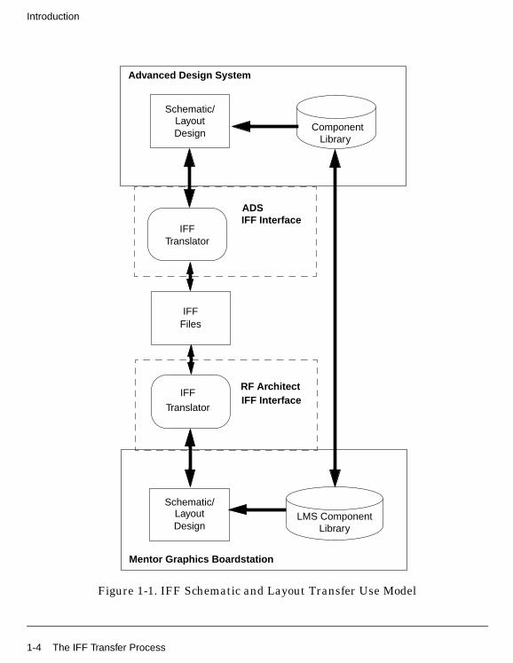
The IFF Transfer ProcessOnce the main requirements have been satisfied, your schematic can be transferredbetween Advanced Design System and Mentor Graphics Boardstation. Importing andexporting can be initiated from either EDA design environment.
The diagram shown in Figure 1-1 describes the general use model for translating adesign using the IFF Interface as it applies to Advanced Design System and MentorGraphics Boardstation. The link between the two EDA environments is establishedvia the ADS and Boardstation IFF Interface. The two component libraries in bothADS and Boardstation must be compatible to support an IFF translation.
For more information on the library requirements, refer to Chapter 2, Before Usingthe IFF Translators.
Main Requirements 1-3
Introduction
Figure 1-1. IFF Schematic and Layout Transfer Use Model
LayoutSchematic/
Design
IFFTranslator
IFF Interface
Advanced Design System
IFFFiles
LayoutSchematic/
Design
IFF
TranslatorIFF Interface
Mentor Graphics Boardstation
ADS
RF Architect
ComponentLibrary
LibraryLMS Component
1-4 The IFF Transfer Process
What’s in this ManualThe goal of this manual is to help you get started, providing relevant examples thatteach you how to set up and use the software, and showing you where you can getmore information as you need it. This manual contains the following:
• Chapter 2, Before Using the IFF Translators describes how to configure yourMentor Graphics environment to support IFF translation between ADS andBoardstation. This chapter also discusses some of the issues related to IFFschematic translation in the ADS and Boardstation environments.
• Chapter 3, Importing IFF Schematic Files into ADS describes the procedure forimporting an IFF file into an Advanced Design System Schematic.
• Chapter 4, Exporting IFF Schematic Files from ADS describes the procedure forexporting an ADS Schematic to an IFF file from Advanced Design System.
• Chapter 5, Importing IFF Files into Mentor Graphics describes the procedurefor importing an IFF file into Boardstation for use in Design Architect.
• Chapter 6, Exporting Designs to IFF from Boardstation describes the procedurefor exporting a Design Architect Schematic to an IFF file from Boardstation.
• Chapter 7, Importing IFF Layout Files into ADS describes the procedure forimporting an IFF file into an Advanced Design System Layout.
• Chapter 8, Exporting IFF Layout Files from ADS describes the procedure forexporting an ADS Layout to an IFF file from Advanced Design System.
What’s in this Manual 1-5
Introduction
About Design TranslationIt is highly recommended that the IFF Translator be used for schematic and layouttranslation only when compatible component libraries exist in the two environmentsthat have been developed to support this translation process. The IFF Translator canalso be used to perform partial translation of a Mentor Graphics library into an ADSlibrary and vice versa. To complete the translation task however, a significantamount of manual intervention is required.
This manual exclusively covers the schematic translation aspect of IFF translations.If you’re interested in translating a component library from Mentor Graphics to ADS,Agilent Technologies Solution Services can provide you with specialized tools andhelp. For more information, contact your Agilent Technologies sales representative.
1-6 About Design Translation
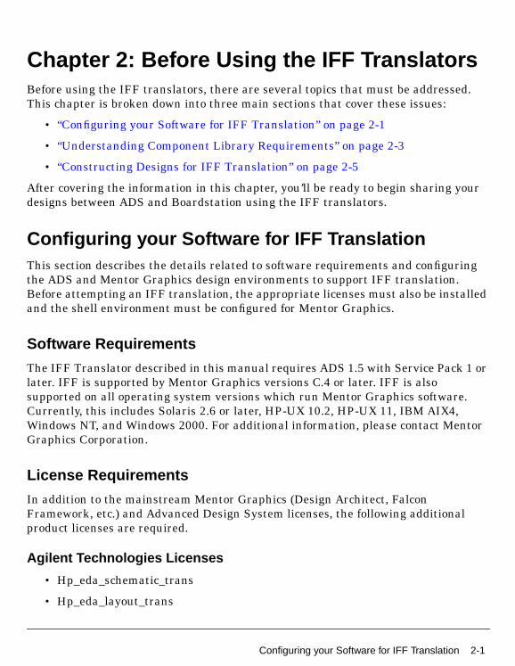
Chapter 2: Before Using the IFF TranslatorsBefore using the IFF translators, there are several topics that must be addressed.This chapter is broken down into three main sections that cover these issues:
• “Configuring your Software for IFF Translation” on page 2-1
• “Understanding Component Library Requirements” on page 2-3
• “Constructing Designs for IFF Translation” on page 2-5
After covering the information in this chapter, you’ll be ready to begin sharing yourdesigns between ADS and Boardstation using the IFF translators.
Configuring your Software for IFF TranslationThis section describes the details related to software requirements and configuringthe ADS and Mentor Graphics design environments to support IFF translation.Before attempting an IFF translation, the appropriate licenses must also be installedand the shell environment must be configured for Mentor Graphics.
Software Requirements
The IFF Translator described in this manual requires ADS 1.5 with Service Pack 1 orlater. IFF is supported by Mentor Graphics versions C.4 or later. IFF is alsosupported on all operating system versions which run Mentor Graphics software.Currently, this includes Solaris 2.6 or later, HP-UX 10.2, HP-UX 11, IBM AIX4,Windows NT, and Windows 2000. For additional information, please contact MentorGraphics Corporation.
License Requirements
In addition to the mainstream Mentor Graphics (Design Architect, FalconFramework, etc.) and Advanced Design System licenses, the following additionalproduct licenses are required.
Agilent Technologies Licenses
• Hp_eda_schematic_trans
• Hp_eda_layout_trans
Configuring your Software for IFF Translation 2-1
Before Using the IFF Translators
Note Before continuing, ensure that you have a valid license for the ADS schematicand layout environment. For more information on ADS Licenses, refer to “Setting upLicenses on UNIX Systems” in the ADS Installation on UNIX Systems manual.
Mentor Graphics Licenses
• RF Architect license (pcbrarch)
• RF Layout license (pcbrflayout)
Note This and all other Mentor Graphics licenses must be purchased from MentorGraphics Corporation.
Setting Environment for Mentor Graphics
Mentor Graphics requires some special environment variables to be set so that theirRF Architect product will be available in Design Architect. This section describes theinformation that must be added your environment, as well as the libraries thatshould be added to the Mentor Graphics location map file. This information isprovided for convenience only. To obtain up-to-date information, refer to MentorGraphic’s RF Design Tools User’s and Reference Manual (rf_useref.pdf), which isdistributed with Mentor Graphic’s RF Architect product.
The following environment variables must be set, either in your UNIX profile (.cshrcor .profile depending on your shell), or in the system environment on Windows NT:
• MGC_HOME - Set this to the Mentor Graphics installation directory
• MGC_LOCATION_MAP - Set this to the full path of the location map file youwish to use.
• AMPLE_PATH - Add the path $MGC_HOME/pkgs/pcb_rf/userware/En_na tothe value of AMPLE_PATH (delimit multiple paths with colons). On WindowsNT, add %MGC_HOME%\pkgs\pcb_rf\userware\En_na (delimit multiplepaths with semicolons). Including this directory in the Ample path will allowMentor Graphics to load the add on software required for doing IFF importsand exports from ADS.
• MGC_RF_SYSTEM - Set the value to ADS
2-2 Configuring your Software for IFF Translation
Note Ample is Mentor Graphic’s C/lisp-like interpretive programming language forframework and database integration.
Add the following libraries to your location map file:
• $MGC_ADSLIB - This is the Mentor Graphics equivalent library for ADSprimitive components. This library is primarily used for drawing transmissionline elements. A tar file containing this library is located at$MGC_HOME/pkgs/pcb_rf/data/lib. Consult your librarian to get the locationwhere the library has been installed.
• $HPEESOF_LIBS - This is the Mentor Graphics equivalent library for ADSconnectors. It contains ADS ports that can be used for generating hierarchicaldesigns. A tar file containing this library is located at$MGC_HOME/pkgs/hpeesof_int/data/lib. Consult your librarian to get thelocation where the library has been installed.
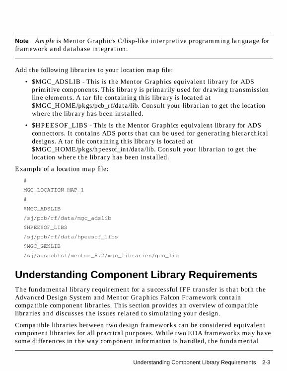
Example of a location map file:
#
MGC_LOCATION_MAP_1
#
$MGC_ADSLIB
/sj/pcb/rf/data/mgc_adslib
$HPEESOF_LIBS
/sj/pcb/rf/data/hpeesof_libs
$MGC_GENLIB
/sj/auspcbfs1/mentor_8.2/mgc_libraries/gen_lib
Understanding Component Library RequirementsThe fundamental library requirement for a successful IFF transfer is that both theAdvanced Design System and Mentor Graphics Falcon Framework containcompatible component libraries. This section provides an overview of compatiblelibraries and discusses the issues related to simulating your design.
Compatible libraries between two design frameworks can be considered equivalentcomponent libraries for all practical purposes. While two EDA frameworks may havesome differences in the way component information is handled, the fundamental
Understanding Component Library Requirements 2-3
Before Using the IFF Translators
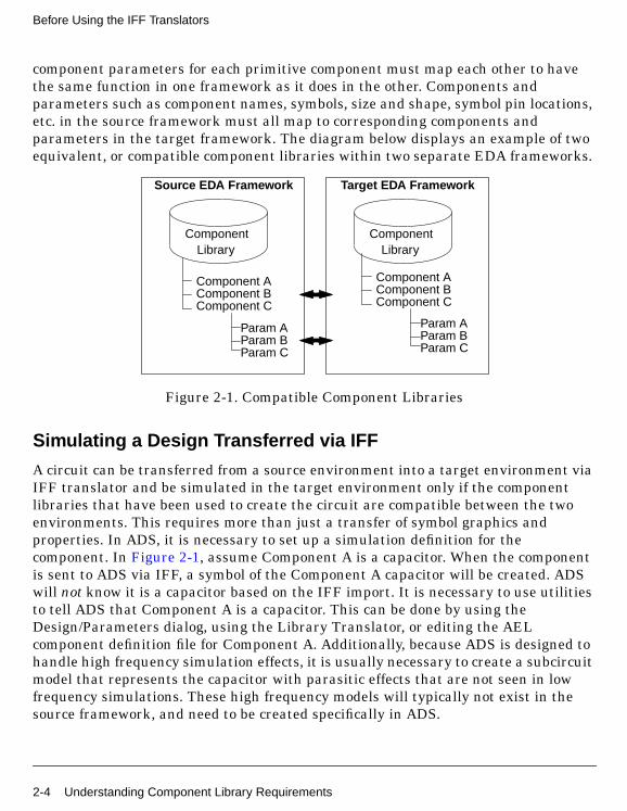
component parameters for each primitive component must map each other to havethe same function in one framework as it does in the other. Components andparameters such as component names, symbols, size and shape, symbol pin locations,etc. in the source framework must all map to corresponding components andparameters in the target framework. The diagram below displays an example of twoequivalent, or compatible component libraries within two separate EDA frameworks.
Figure 2-1. Compatible Component Libraries
Simulating a Design Transferred via IFF
A circuit can be transferred from a source environment into a target environment viaIFF translator and be simulated in the target environment only if the componentlibraries that have been used to create the circuit are compatible between the twoenvironments. This requires more than just a transfer of symbol graphics andproperties. In ADS, it is necessary to set up a simulation definition for thecomponent. In Figure 2-1, assume Component A is a capacitor. When the componentis sent to ADS via IFF, a symbol of the Component A capacitor will be created. ADSwill not know it is a capacitor based on the IFF import. It is necessary to use utilitiesto tell ADS that Component A is a capacitor. This can be done by using theDesign/Parameters dialog, using the Library Translator, or editing the AELcomponent definition file for Component A. Additionally, because ADS is designed tohandle high frequency simulation effects, it is usually necessary to create a subcircuitmodel that represents the capacitor with parasitic effects that are not seen in lowfrequency simulations. These high frequency models will typically not exist in thesource framework, and need to be created specifically in ADS.
ComponentLibrary
ComponentLibrary
Source EDA Framework Target EDA Framework
Component AComponent BComponent C
Component AComponent BComponent C
Param AParam BParam C
Param AParam BParam C
2-4 Understanding Component Library Requirements
Getting Help
Due to the detailed nature of creating compatible component libraries, it isrecommended that you consult Agilent EEsof-EDA Solution Services for moreinformation. Solution Services can provide training on how to configure compatiblecomponent libraries as well as complete library development solutions. Contact yourlocal Agilent Technologies sales representative for more information on working withSolution Services.
Constructing Designs for IFF Translation
The IFF translator module enables bi-directional, fully hierarchical schematic andlayout transfer between the ADS and Mentor Graphics Boardstation. You can edityour schematic and layout in either environment, and when you transfer editedmaterial to the other environment, all edits are preserved, including propertychanges.
Before attempting to transfer a design via IFF, ensure that all component librariesare compatible in all frameworks. This step is essential for a successful IFF transfer.For more information on compatible libraries, refer to “Understanding ComponentLibrary Requirements” on page 2-3.
To have a successful IFF transfer, it is required that only components that arecontained within the compatible libraries be used in your designs. A hierarchicaldesign approach is recommended for the implementation of RF Board designs inADS.
Separating Simulation Control Elements
Simulation control elements are not transferred between ADS and Mentor Graphics.Because of the different way the two environments handle simulation setup, it isrecommended that your simulation control elements in Advanced Design System beseparated from your circuit schematic information using a hierarchical approach (i.e.top level contains simulation control and instance(s) of subcircuits containing DUT).This enables you to transfer only the schematic information in the subcircuit and willrequire you to set up simulation controls independently in the Mentor Graphicsenvironment. For more information, refer to “Creating Hierarchical Designs” in theADS “User’s Guide”.
Understanding Component Library Requirements 2-5
Before Using the IFF Translators
Known Issues and LimitationsThere are several known issues or limitations that you should become familiar withbefore attempting to perform an IFF translation.
• Only one schematic is allowed per cell in Advanced Design System.
• Only one symbol is allowed per cell in Advanced Design System.
• Only one layout is allowed per cell in Advanced Design System.
• Schematic view points can not be exported from Mentor Graphics. Only thebase schematic can be translated. This means that package annotations thatare annotated to a view point can not be sent to Advanced Design System.
2-6 Known Issues and Limitations
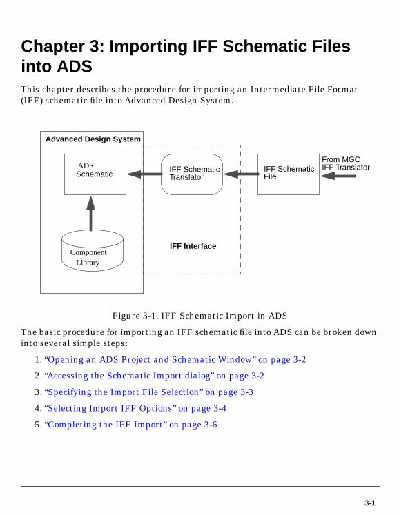
Chapter 3: Importing IFF Schematic Filesinto ADSThis chapter describes the procedure for importing an Intermediate File Format(IFF) schematic file into Advanced Design System.
Figure 3-1. IFF Schematic Import in ADS
The basic procedure for importing an IFF schematic file into ADS can be broken downinto several simple steps:
1. “Opening an ADS Project and Schematic Window” on page 3-2
2. “Accessing the Schematic Import dialog” on page 3-2
3. “Specifying the Import File Selection” on page 3-3
4. “Selecting Import IFF Options” on page 3-4
5. “Completing the IFF Import” on page 3-6
SchematicIFF SchematicIFF Schematic
Translator
Advanced Design System
IFF Interface
File
From MGCIFF TranslatorADS
ComponentLibrary
3-1
Importing IFF Schematic Files into ADS
Opening an ADS Project and Schematic WindowOpen a project in ADS before attempting to import your design. Working in projectdirectories enables the translator to organize design files in the standard ADS filestructure. The import option will not be active in the File menu unless you open aproject. From the ADS Main window:
1. Choose File > New Project to open a new project or File > Open Project to open anexisting project.
For more information on working in project directories, refer to “ManagingProjects and Designs” in the ADS “User’s Guide”.
2. Before invoking the import procedure, close any open designs to remove anyactive designs from memory. In the ADS Main window, choose File > Close All .
3. Open a new ADS Schematic window by clicking the New Schematic Windowicon in the ADS Main window tool bar.
A new ADS untitled schematic window appears.
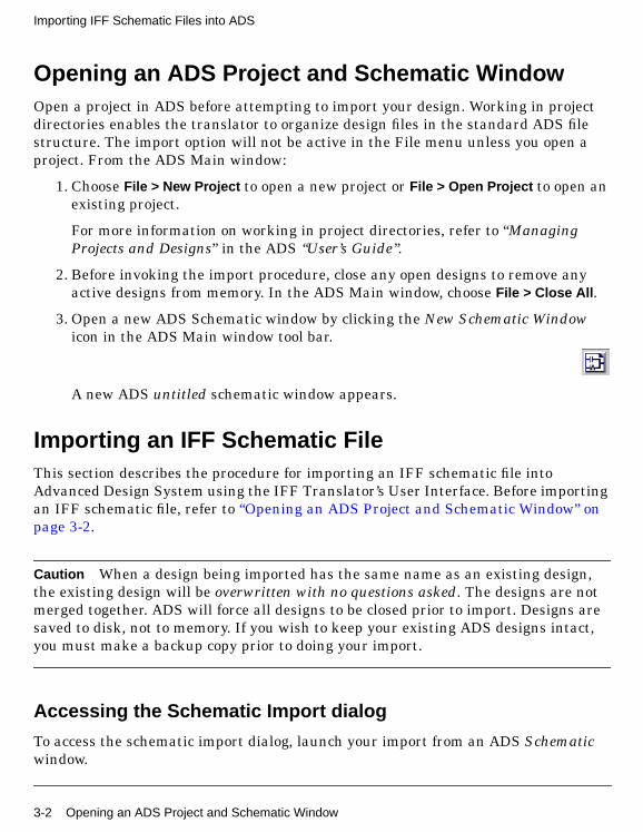
Importing an IFF Schematic FileThis section describes the procedure for importing an IFF schematic file intoAdvanced Design System using the IFF Translator’s User Interface. Before importingan IFF schematic file, refer to “Opening an ADS Project and Schematic Window” onpage 3-2.
Caution When a design being imported has the same name as an existing design,the existing design will be overwritten with no questions asked. The designs are notmerged together. ADS will force all designs to be closed prior to import. Designs aresaved to disk, not to memory. If you wish to keep your existing ADS designs intact,you must make a backup copy prior to doing your import.
Accessing the Schematic Import dialog
To access the schematic import dialog, launch your import from an ADS Schematicwindow.
3-2 Opening an ADS Project and Schematic Window
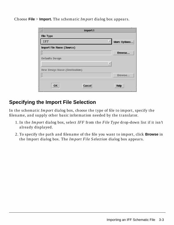
Choose File > Import. The schematic Import dialog box appears.
Specifying the Import File Selection
In the schematic Import dialog box, choose the type of file to import, specify thefilename, and supply other basic information needed by the translator.
1. In the Import dialog box, select IFF from the File Type drop-down list if it isn’talready displayed.
2. To specify the path and filename of the file you want to import, click Browse inthe Import dialog box. The Import File Selection dialog box appears.
Importing an IFF Schematic File 3-3
Importing IFF Schematic Files into ADS
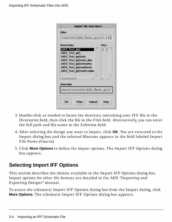
3. Double-click as needed to locate the directory containing your IFF file in theDirectories field, then click the file in the Files field. Alternatively, you can enterthe full path and file name in the Selection field.
4. After selecting the design you want to import, click OK. You are returned to theImport dialog box and the selected filename appears in the field labeled ImportFile Name (Source).
5. Click More Options to define the import options. The Import IFF Options dialogbox appears.
Selecting Import IFF Options
This section describes the choices available in the Import IFF Options dialog box.Import options for other file formats are detailed in the ADS “Importing andExporting Designs” manual.
To access the schematic Import IFF Options dialog box from the Import dialog, clickMore Options . The schematic Import IFF Options dialog box appears.
3-4 Importing an IFF Schematic File
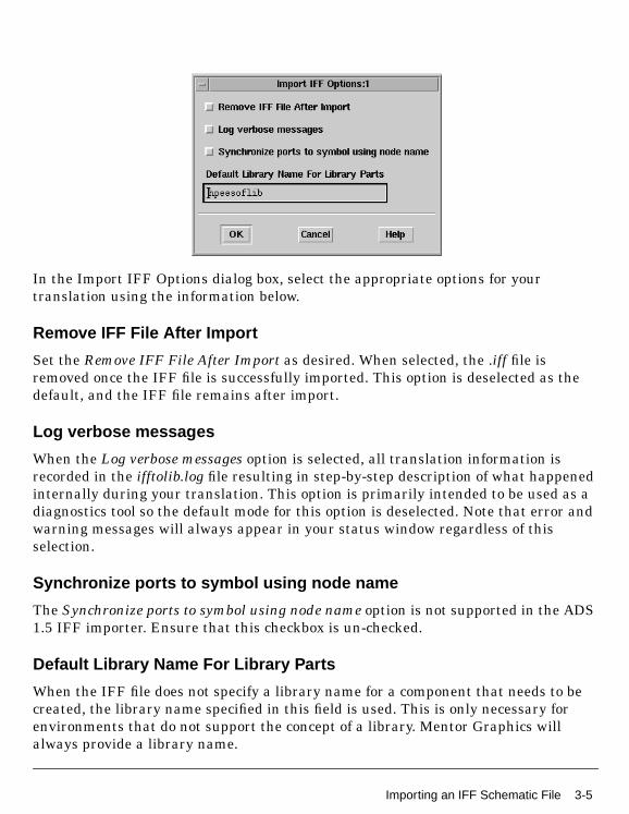
In the Import IFF Options dialog box, select the appropriate options for yourtranslation using the information below.
Remove IFF File After Import
Set the Remove IFF File After Import as desired. When selected, the .iff file isremoved once the IFF file is successfully imported. This option is deselected as thedefault, and the IFF file remains after import.
Log verbose messages
When the Log verbose messages option is selected, all translation information isrecorded in the ifftolib.log file resulting in step-by-step description of what happenedinternally during your translation. This option is primarily intended to be used as adiagnostics tool so the default mode for this option is deselected. Note that error andwarning messages will always appear in your status window regardless of thisselection.
Synchronize ports to symbol using node name
The Synchronize ports to symbol using node name option is not supported in the ADS1.5 IFF importer. Ensure that this checkbox is un-checked.
Default Library Name For Library Parts
When the IFF file does not specify a library name for a component that needs to becreated, the library name specified in this field is used. This is only necessary forenvironments that do not support the concept of a library. Mentor Graphics willalways provide a library name.
Importing an IFF Schematic File 3-5
Importing IFF Schematic Files into ADS
Note The Default Library Name For Library Parts field is identical to the field of thesame name in the Export IFF Options dialog box. Changes made to this field willmodify the contents of the field in the Export IFF Options dialog box. For moreinformation on Exporting IFF Schematic files, refer to “Exporting IFF SchematicFiles from ADS” on page 4-1.
About Component Libraries
A component library in Advanced Design System consists of a collection of componentdefinitions. Each primitive component has an associated component name, symboland predefined component parameters that include relevant physical and electricalcharacteristics.
The IFF translator can be used as the initial step in creating an ADS componentlibrary however; this topic is outside of the scope of this manual. Creating an ADScomponent library using IFF requires specialized tools and training. If you’reinterested in learning more about this topic, contact Agilent EEsof-EDA’s SolutionServices.
Completing the IFF Import
After specifying the IFF import options, click OK in the Import IFF Options dialog boxto save your settings or Cancel to retain the default settings. After clicking OK, youare returned to the Import dialog box. Click OK to begin the translation.
When translation is complete, an Information Message dialog box appears statingIFF Import Completed. The IFF Import log window also appears. Review the logmessage searching for any error messages or warnings generated during export.
3-6 Importing an IFF Schematic File
Chapter 4: Exporting IFF Schematic Filesfrom ADSThis chapter describes the procedure for exporting an Intermediate File Format (IFF)schematic from Advanced Design System.
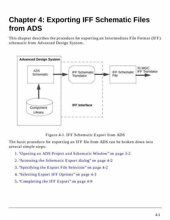
Figure 4-1. IFF Schematic Export from ADS
The basic procedure for exporting an IFF file from ADS can be broken down intoseveral simple steps:
1. “Opening an ADS Project and Schematic Window” on page 3-2
2. “Accessing the Schematic Export dialog” on page 4-2
3. “Specifying the Export File Selection” on page 4-2
4. “Selecting Export IFF Options” on page 4-3
5. “Completing the IFF Export” on page 4-9
Schematic
Component
IFF SchematicIFF SchematicTranslator
Advanced Design System
IFF Interface
File
To MGCIFF TranslatorADS
Library
4-1
Exporting IFF Schematic Files from ADS
Exporting an IFF Schematic FileThis section describes the procedure for exporting an IFF schematic file fromAdvanced Design System using the IFF Translator’s User Interface. Before exportingan IFF schematic file, refer to “Opening an ADS Project and Schematic Window” onpage 3-2.
Accessing the Schematic Export dialog
To access the schematic export dialog, launch your export from an ADS Schematicwindow.
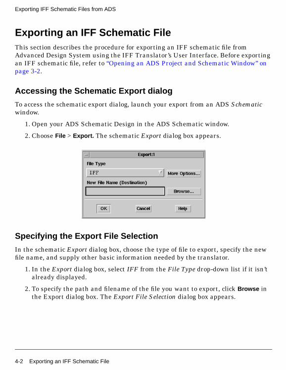
1. Open your ADS Schematic Design in the ADS Schematic window.
2. Choose File > Export. The schematic Export dialog box appears.
Specifying the Export File Selection
In the schematic Export dialog box, choose the type of file to export, specify the newfile name, and supply other basic information needed by the translator.
1. In the Export dialog box, select IFF from the File Type drop-down list if it isn’talready displayed.
2. To specify the path and filename of the file you want to export, click Browse inthe Export dialog box. The Export File Selection dialog box appears.
4-2 Exporting an IFF Schematic File
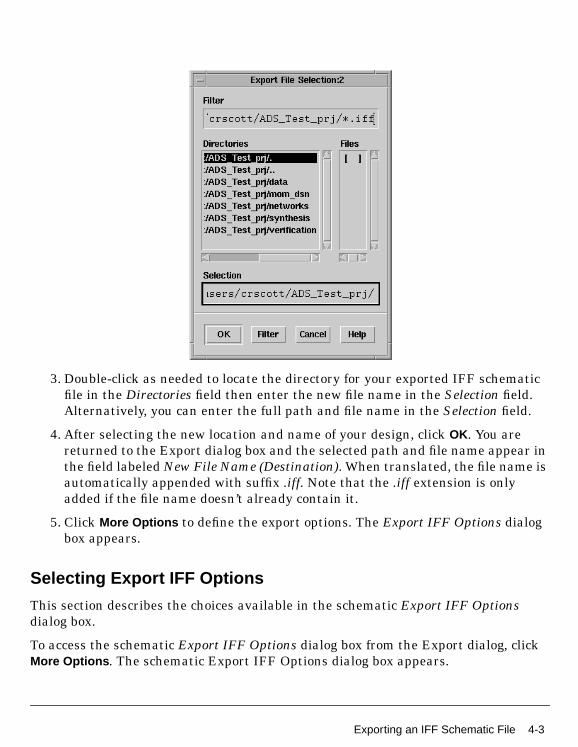
3. Double-click as needed to locate the directory for your exported IFF schematicfile in the Directories field then enter the new file name in the Selection field.Alternatively, you can enter the full path and file name in the Selection field.
4. After selecting the new location and name of your design, click OK. You arereturned to the Export dialog box and the selected path and file name appear inthe field labeled New File Name (Destination). When translated, the file name isautomatically appended with suffix .iff. Note that the .iff extension is onlyadded if the file name doesn’t already contain it.
5. Click More Options to define the export options. The Export IFF Options dialogbox appears.
Selecting Export IFF Options
This section describes the choices available in the schematic Export IFF Optionsdialog box.
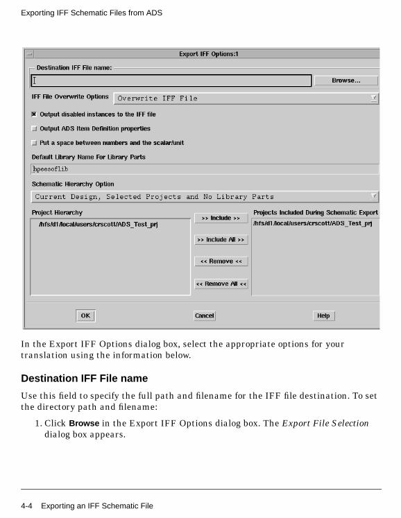
To access the schematic Export IFF Options dialog box from the Export dialog, clickMore Options . The schematic Export IFF Options dialog box appears.
Exporting an IFF Schematic File 4-3
Exporting IFF Schematic Files from ADS
In the Export IFF Options dialog box, select the appropriate options for yourtranslation using the information below.
Destination IFF File name
Use this field to specify the full path and filename for the IFF file destination. To setthe directory path and filename:
1. Click Browse in the Export IFF Options dialog box. The Export File Selectiondialog box appears.
4-4 Exporting an IFF Schematic File
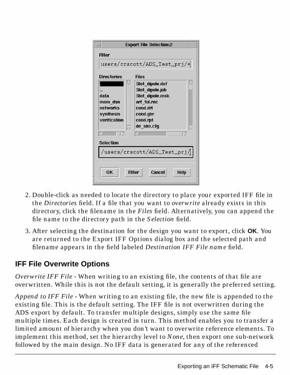
2. Double-click as needed to locate the directory to place your exported IFF file inthe Directories field. If a file that you want to overwrite already exists in thisdirectory, click the filename in the Files field. Alternatively, you can append thefile name to the directory path in the Selection field.
3. After selecting the destination for the design you want to export, click OK. Youare returned to the Export IFF Options dialog box and the selected path andfilename appears in the field labeled Destination IFF File name field.
IFF File Overwrite Options
Overwrite IFF File - When writing to an existing file, the contents of that file areoverwritten. While this is not the default setting, it is generally the preferred setting.
Append to IFF File - When writing to an existing file, the new file is appended to theexisting file. This is the default setting. The IFF file is not overwritten during theADS export by default. To transfer multiple designs, simply use the same filemultiple times. Each design is created in turn. This method enables you to transfer alimited amount of hierarchy when you don’t want to overwrite reference elements. Toimplement this method, set the hierarchy level to None, then export one sub-networkfollowed by the main design. No IFF data is generated for any of the referenced
Exporting an IFF Schematic File 4-5
Exporting IFF Schematic Files from ADS
components in either design, so the only two circuits overwritten during an importare the two designs transferred.
Output disabled instances to the IFF file
When this option is selected, if an instance is deactivated in the schematic, it will stillbe output into the IFF file. If the checkbox is deselected (default), deactivatedinstances will not be exported. This option can be utilized to omit certain componentsfrom being transferred to remote environments that might not support thecomponents (e.g. deactivate the simulation components prior to creating an IFF file tosend to Mentor Graphics, which does not have any definitions for the simulatorcomponents). Check this option if you want to get everything. Uncheck this option ifyou want to filter out the unused/unwanted components.
Output ADS Item Definition properties
When this option is selected, ADS Item Definition properties are utilized to recreatethe information necessary to simulate a component for ADS. For example, if you haveparameters on a resistor, some Item Definition properties are created in the IFF file(e.g. R_ADS_UNIT=1), which allow the IFF importer to exactly recreate thecomponent as it exists in ADS. However, other tools will not recognize the ItemDefinition parameters, and may misinterpret the properties as being separate. Iflibrary symbols are being exported to other environments that do not recognize theADS Item Definition parameters, the option should be turned off. This option isdeselected by default.
Put a space between numbers and the scalar/unit
When this option is selected, parameter values are exported as they normally appearin ADS (i.e. with a space between the number and the scalar, e.g. “1 pF”). If thecheckbox is deactivated, the exporter converts the values into the IFF valuespecification, which is to have no space between a number and a scalar (e.g. "1pF").Ideally, an IFF exporter should interpret either form of number, and set the valueinternally to whatever is normal for that environment. Some environments (e.g.Mentor Graphics) do not interpret the IFF property values in any way. For Mentor IC,this means the numbers need to have no space in them, because when they are usedwithin SPICE simulations, the space will cause syntax errors in the simulator.However, for Mentor Board, they require the ADS components to have a space inthem because the RF Architect ADS library is set up to expect values to have a spacebetween a number and a scalar/unit.
4-6 Exporting an IFF Schematic File
If you are exporting designs to Mentor Boardstation, you must select this option forIFF imports to work into their environment. An additional issue can come up if youcreate variables, and then assign scalar values to the variable (e.g. "R1 kOhms").When this is exported, if the option is not set, it would convert to "R1koh", whichcould no longer be interpreted correctly. Note that this second option is consideredbad practice (the scalar should be included in the variable value for R1, and no unitsshould be specified); however, ADS does allow you to format variables in this way. Ifyou are using variables in this way, you must set this option to true. This option isdeselected by default.
Default Library Name for Library Parts
When the IFF file does not specify a library name for a component that needs to becreated, the library name specified in this field is used. This is necessary forenvironments that do not support the concept of a library.
Design objects are stored in a group that uses the same name as the project directory,but library parts are stored in either the default library hpeesoflib or a library thatyou specify. The default library name can contain only alpha numeric characters.
Note The Default Library Name For Library Parts field is identical to the field of thesame name in the Import IFF Options dialog box. Changes made to this field willmodify the contents of the field in the Import IFF Options dialog box.
About Component Libraries
A component library in ADS consists of a collection of component definitions. Eachprimitive component has an associated component name, symbol and predefinedcomponent parameters that include relevant physical and electrical characteristics.
The IFF Translator can be used as the initial step in creating an ADS componentlibrary however, this topic is outside of the scope of this manual. Creating an ADScomponent library using IFF requires specialized tools and training. If you’reinterested in learning more about this topic, contact Agilent EEsof-EDA’s SolutionServices.
Schematic Hierarchy Option
The Schematic Hierarchy Option drop-down list enables you to establish how much ofthe schematic hierarchy is exported:
Exporting an IFF Schematic File 4-7
Exporting IFF Schematic Files from ADS
Current Design Only Write current level only. Complete design information for thecurrent design is exported. Instance-specific information (parameter values andcoordinates identifying position) is also exported. Detailed definitions of areferenced design are not exported.
Current Design, Selected Projects and No Library Parts Complete designinformation for the current design is exported. Referenced designs that reside in aproject selected for inclusion during export and are part of the current design’shierarchy are also exported. Library parts are not exported. This is the defaultsetting.
Current Design, Selected Projects and All Library Parts Complete designinformation for the current design is exported. Referenced designs that reside in aproject selected for inclusion during export and are part of the current design’shierarchy are also exported. In addition, library parts are exported.
Project Hierarchy
Displays the current project. If hierarchical, all included projects are listed in theappropriate order.
Projects Included During Schematic Export
This field contains the projects for which schematic design information is exported.You can customize this list if the current project is hierarchical.
To add a project to this list:
1. In the Project Hierarchy list, click the desired project.
2. Click the Include button. The project is added to the Projects Included list.
To include all projects, click Include All .
To remove a project from the Projects Included list:
1. In the Projects Included list, click the entry you want to remove.
2. Click the Remove button. The project is removed from the list.
To remove all entries from the Projects Included list, click Remove All .
This is an example of using the Project Hierarchy and Projects Included DuringSchematic Export fields. First you make a project called Proj_A that includes severaldesigns. Then you make another project called Proj_B and you want to reuse some of
4-8 Exporting an IFF Schematic File
the designs from project Proj_A in project Proj_B. You can then include Proj_A inProj_B by using the Include button to have access to all the designs in Proj_A afteryour export is complete.
Completing the IFF Export
After specifying the IFF export options, click OK in the Export IFF Options dialog boxto save your settings or Cancel to retain the default settings. After clicking OK, youare returned to the Export dialog box. Click OK to begin the translation.
When translation is complete, an Information Message dialog box appears stating,IFF Export Completed. The IFF Export log window also appears. Review the logmessage searching for any error messages or warnings generated during export.
Exporting an IFF Schematic File 4-9

Exporting IFF Schematic Files from ADS
4-10 Exporting an IFF Schematic File
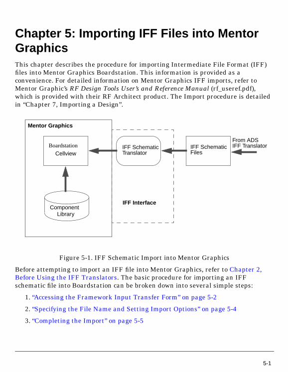
Chapter 5: Importing IFF Files into MentorGraphicsThis chapter describes the procedure for importing Intermediate File Format (IFF)files into Mentor Graphics Boardstation. This information is provided as aconvenience. For detailed information on Mentor Graphics IFF imports, refer toMentor Graphic’s RF Design Tools User’s and Reference Manual (rf_useref.pdf),which is provided with their RF Architect product. The Import procedure is detailedin “Chapter 7, Importing a Design”.
Figure 5-1. IFF Schematic Import into Mentor Graphics
Before attempting to import an IFF file into Mentor Graphics, refer to Chapter 2,Before Using the IFF Translators. The basic procedure for importing an IFFschematic file into Boardstation can be broken down into several simple steps:
1. “Accessing the Framework Input Transfer Form” on page 5-2
2. “Specifying the File Name and Setting Import Options” on page 5-4
3. “Completing the Import” on page 5-5
Cellview
Component
IFF SchematicIFF SchematicTranslator
Mentor Graphics
IFF Interface
Files
From ADSIFF TranslatorBoardstation
Library
5-1
Importing IFF Files into Mentor Graphics
Importing an IFF Schematic FileThis section describes the procedure for importing an IFF schematic file into theMentor Graphics Boardstation using the IFF Translator’s User Interface. Beforeimporting an IFF schematic file, refer to the beginning of Chapter 5, Importing IFFFiles into Mentor Graphics.
The menu items described in this section are only if the appropriate Ample path hasbeen set up for the RF Architect option of Design Architect. For more information,refer to Chapter 2, Before Using the IFF Translators.
Accessing the Framework Input Transfer Form
To access the schematic import dialog, launch your import from the BoardstationDesign Architect window.
1. In a terminal window, change to the appropriate directory.
2. Run Design Architect by typing the appropriate command (typically da orda_lms). The Mentor Graphics Design Architect window appears.
5-2 Importing an IFF Schematic File
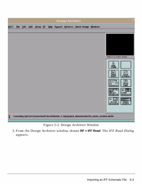
Figure 5-2. Design Architect Window
3. From the Design Architect window, choose RF > IFF Read. The IFF Read Dialogappears.
Importing an IFF Schematic File 5-3
Importing IFF Files into Mentor Graphics
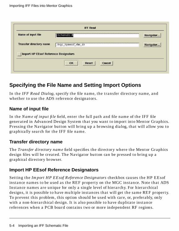
Specifying the File Name and Setting Import Options
In the IFF Read Dialog, specify the file name, the transfer directory name, andwhether to use the ADS reference designators.
Name of input file
In the Name of input file field, enter the full path and file name of the IFF filegenerated in Advanced Design System that you want to import into Mentor Graphics.Pressing the Navigator button will bring up a browsing dialog, that will allow you tographically search for the IFF file name.
Transfer directory name
The Transfer directory name field specifies the directory where the Mentor Graphicsdesign files will be created. The Navigator button can be pressed to bring up agraphical directory browser.
Import HP EEsof Reference Designators
Setting the Import HP EEsof Reference Designators checkbox causes the HP EEsofinstance names to be used as the REF property on the MGC instance. Note that ADSInstance names are unique for only a single level of hierarchy. For hierarchicaldesigns, it is possible to have multiple instances that will get the same REF property.To prevent this problem, this option should be used with care, or, preferably, onlywith a non-hierarchical design. It is also possible to have duplicate instancereferences when a PCB board contains two or more independent RF regions.
5-4 Importing an IFF Schematic File
Completing the Import
After you have filled in the fields of the IFF Read Dialog, click OK to begin thetranslation. You can also click Cancel to abort the import operation. The Reset tobutton will reset the fields to the default values (“./schematic.iff” and“./mgc_hpeesof_xfer_dir”).
After the translation begins, all import log information is displayed in the terminalwindow that Design Architect was started from. One of the log lines will display whatwas created. Any warnings or error messages encountered during the translation arealso displayed in the log messages. After the import is completed, the log informationwill be displayed in Notepad window.
While cells are created in the appropriate directory, the cell view is not automaticallydisplayed in the Design Architect. If full hierarchy was specified for the AdvancedDesign System export, existing schematics common to both program environmentsare overwritten on import.
Setting Up a Library Search Path
This information is repeated from Mentor Graphics RF Design Tools User’s andReference Manual. The RF LAYOUT, DA and LIBRARIAN options support searchingfor the library symbols used in a RF design in $HPEESOF_LIBS directory, based onan entry defined in the location map in Mentor Graphics environment. This is alsoapplicable to user-defined symbol libraries. Additionally, you can set theenvironmental variable $MGC_RF_LIB_SEARCH_PATH which makes all thesymbols for the packaged parts available. For example,
setenv MGC_RF_LIB_SEARCH_PATH /company_lib/resistors:/company_lib/caps:/company_lib/relays
Note that the colon (:) is required between the libraries.
This setup is essential if you use translated LMS parts in the HP EEsof environment.This search path provides the symbol mapping path information for the design IFFtranslation process.
Importing an IFF Schematic File 5-5

Importing IFF Files into Mentor Graphics
Importing an IFF Layout FileTo access the layout import dialog, launch your import from the Boardstation RFlayout window.
1. Start the RF Layout tool by typing the command layout design -rf. You mayneed to run the to_layout command on your schematic prior to running thiscommand. For more information on running to_layout for an RF design, refer toChapter 3 of Mentor Graphic’s RF Design Tools User’s and Reference Manual(rf_useref.pdf). Your PC Board layout must have an RF Region in it for you toimport a layout IFF file. You cannot create a new RF region through the layouttool, only the to_layout tool can create an RF region.
2. In the layout window, right click to bring up the popup menu, and select themenu option RF > Import IFF into Layout . Use the Navigator button to select anIFF file through a graphical browser.
3. The board you will be importing to must have an RF Region set up. This shouldhave been done by the to_layout command. Select the region you wish to importthe IFF file into. This region should correspond to the schematic that the layoutrepresented in ADS.
Completing the Layout Import
After you have filled in the fields of the Import IFF into LAYOUT Dialog, click OK tobegin the translation. You can also click Cancel to abort the import operation. TheReset to button will reset the fields to the default values.
5-6 Importing an IFF Layout File

After the translation begins, all import log information is displayed in the terminalwindow that RF Layout was started from. One of the log lines will display what wascreated. Any warnings or error messages encountered during the translation are alsodisplayed in the log messages. After the import finishes, the final layout will bedisplayed in the layout window.
Importing an IFF Layout File 5-7

Importing IFF Files into Mentor Graphics
5-8 Importing an IFF Layout File
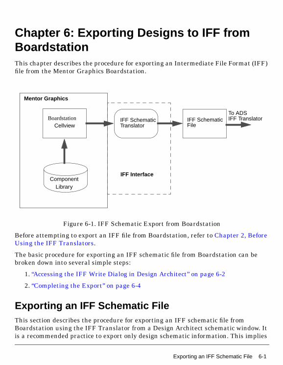
Chapter 6: Exporting Designs to IFF fromBoardstationThis chapter describes the procedure for exporting an Intermediate File Format (IFF)file from the Mentor Graphics Boardstation.
Figure 6-1. IFF Schematic Export from Boardstation
Before attempting to export an IFF file from Boardstation, refer to Chapter 2, BeforeUsing the IFF Translators.
The basic procedure for exporting an IFF schematic file from Boardstation can bebroken down into several simple steps:
1. “Accessing the IFF Write Dialog in Design Architect” on page 6-2
2. “Completing the Export” on page 6-4
Exporting an IFF Schematic FileThis section describes the procedure for exporting an IFF schematic file fromBoardstation using the IFF Translator from a Design Architect schematic window. Itis a recommended practice to export only design schematic information. This implies
Cellview
Component
IFF SchematicIFF SchematicTranslator
Mentor Graphics
IFF Interface
File
To ADSIFF TranslatorBoardstation
Library
Exporting an IFF Schematic File 6-1
Exporting Designs to IFF from Boardstation
excluding everything else from the export process such as simulation control blocksas well as any other elements that do not map directly to Advanced Design System.Such elements should exist at the top cell (symbol) view. To avoid complications,descend one level into this symbol view before beginning the export process.
The menu items described in this section are only available if the correct Ample pathhas been set up for the RF Architect option of Design Architect. For moreinformation, refer to Chapter 2, Before Using the IFF Translators.
Accessing the IFF Write Dialog in Design Architect
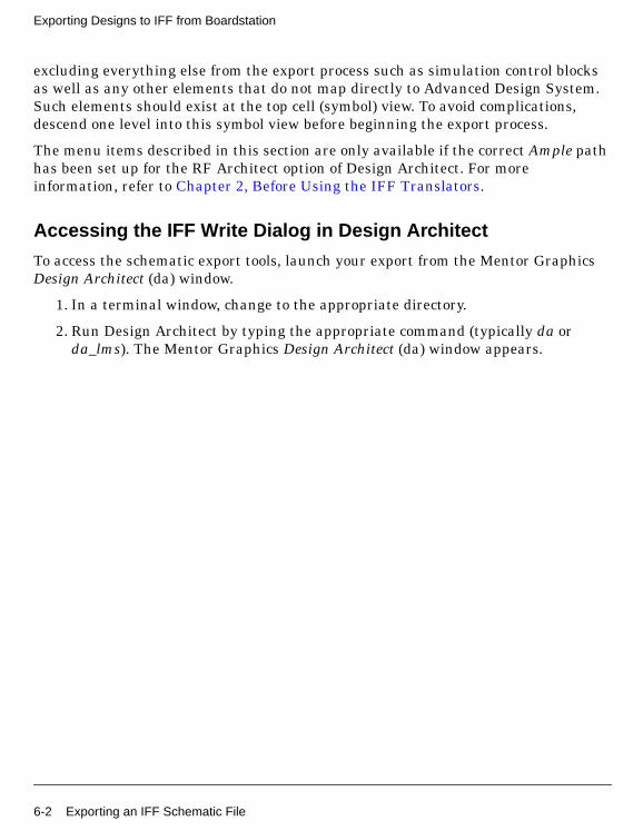
To access the schematic export tools, launch your export from the Mentor GraphicsDesign Architect (da) window.
1. In a terminal window, change to the appropriate directory.
2. Run Design Architect by typing the appropriate command (typically da orda_lms). The Mentor Graphics Design Architect (da) window appears.
6-2 Exporting an IFF Schematic File
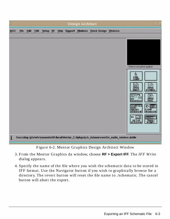
Figure 6-2. Mentor Graphics Design Architect Window
3. From the Mentor Graphics da window, choose RF > Export IFF . The IFF Writedialog appears.
4. Specify the name of the file where you wish the schematic data to be stored inIFF format. Use the Navigator button if you wish to graphically browse for adirectory. The revert button will reset the file name to ./schematic. The cancelbutton will abort the export.
Exporting an IFF Schematic File 6-3
Exporting Designs to IFF from Boardstation
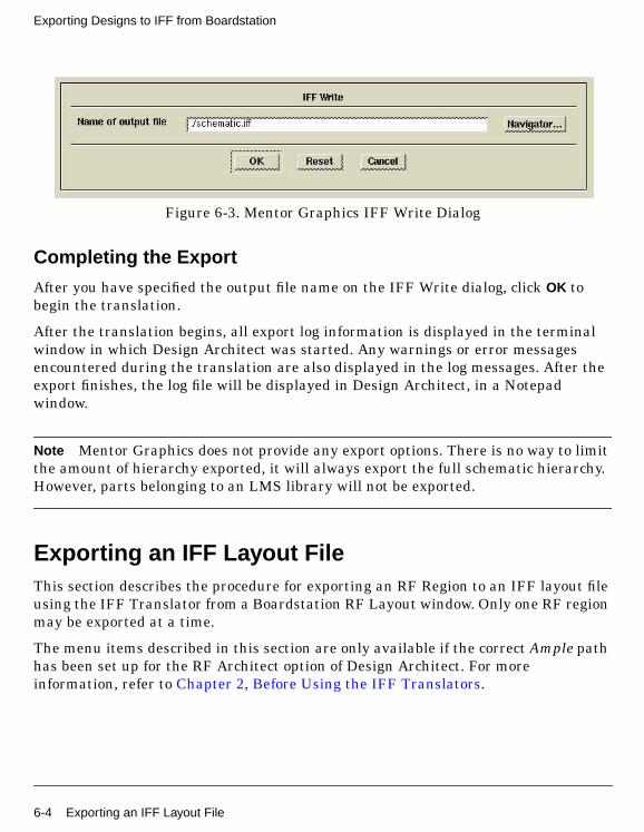
Figure 6-3. Mentor Graphics IFF Write Dialog
Completing the Export
After you have specified the output file name on the IFF Write dialog, click OK tobegin the translation.
After the translation begins, all export log information is displayed in the terminalwindow in which Design Architect was started. Any warnings or error messagesencountered during the translation are also displayed in the log messages. After theexport finishes, the log file will be displayed in Design Architect, in a Notepadwindow.
Note Mentor Graphics does not provide any export options. There is no way to limitthe amount of hierarchy exported, it will always export the full schematic hierarchy.However, parts belonging to an LMS library will not be exported.
Exporting an IFF Layout FileThis section describes the procedure for exporting an RF Region to an IFF layout fileusing the IFF Translator from a Boardstation RF Layout window. Only one RF regionmay be exported at a time.
The menu items described in this section are only available if the correct Ample pathhas been set up for the RF Architect option of Design Architect. For moreinformation, refer to Chapter 2, Before Using the IFF Translators.
6-4 Exporting an IFF Layout File
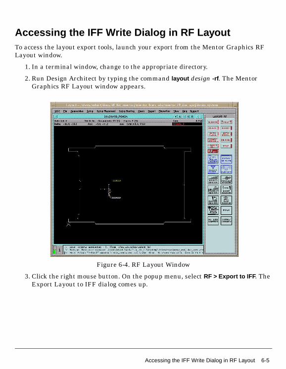
Accessing the IFF Write Dialog in RF LayoutTo access the layout export tools, launch your export from the Mentor Graphics RFLayout window.
1. In a terminal window, change to the appropriate directory.
2. Run Design Architect by typing the command layout design -rf. The MentorGraphics RF Layout window appears.
Figure 6-4. RF Layout Window
3. Click the right mouse button. On the popup menu, select RF > Export to IFF . TheExport Layout to IFF dialog comes up.
Accessing the IFF Write Dialog in RF Layout 6-5

Exporting Designs to IFF from Boardstation
Figure 6-5. Export Layout to IFF Dialog
Output File for IFF
There are two possible choices for this option, Default or Specify. If you leave Defaultchecked, the IFF file will be named automatically, using the naming formula<design>/eesof_pcbinfo/to_hp/<region>.xfer/layout.iff. If you would prefer to outputthe file to a different location, select the Specify radio button. This will change thedialog, so you can enter in your own file pathname. A Navigator button enables you tographically browse for a file name.
Region
There will additionally be a list box, that contains the RF Regions that exist for thecurrent board design. You must select one of these regions. The data for thatparticular RF Region will be output into the IFF file that was specified.
Completing the IFF Export
After specifying the options, click OK in the Export Layout to IFF dialog box to beginthe translation. Press Cancel to abort the export, or Reset to reset the dialog optionsto their original state. Log messages will be output into the terminal window wherethe RF Layout process was started.
6-6 Accessing the IFF Write Dialog in RF Layout
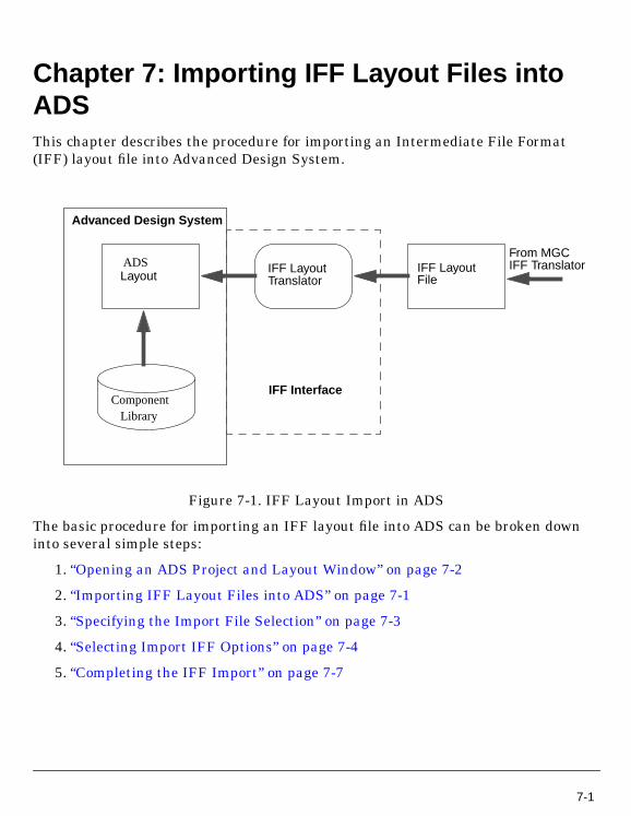
Chapter 7: Importing IFF Layout Files intoADSThis chapter describes the procedure for importing an Intermediate File Format(IFF) layout file into Advanced Design System.
Figure 7-1. IFF Layout Import in ADS
The basic procedure for importing an IFF layout file into ADS can be broken downinto several simple steps:
1. “Opening an ADS Project and Layout Window” on page 7-2
2. “Importing IFF Layout Files into ADS” on page 7-1
3. “Specifying the Import File Selection” on page 7-3
4. “Selecting Import IFF Options” on page 7-4
5. “Completing the IFF Import” on page 7-7
LayoutIFF LayoutIFF Layout
Translator
Advanced Design System
IFF Interface
File
From MGCIFF TranslatorADS
ComponentLibrary
7-1
Importing IFF Layout Files into ADS
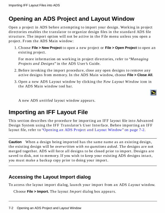
Opening an ADS Project and Layout WindowOpen a project in ADS before attempting to import your design. Working in projectdirectories enables the translator to organize design files in the standard ADS filestructure. The import option will not be active in the File menu unless you open aproject. From the ADS Main window:
1. Choose File > New Project to open a new project or File > Open Project to open anexisting project.
For more information on working in project directories, refer to “ManagingProjects and Designs” in the ADS User’s Guide.
2. Before invoking the import procedure, close any open designs to remove anyactive designs from memory. In the ADS Main window, choose File > Close All .
3. Open a new ADS Layout window by clicking the New Layout Window icon inthe ADS Main window tool bar.
A new ADS untitled layout window appears.
Importing an IFF Layout FileThis section describes the procedure for importing an IFF layout file into AdvancedDesign System using the IFF Translator’s User Interface. Before importing an IFFlayout file, refer to “Opening an ADS Project and Layout Window” on page 7-2.
Caution When a design being imported has the same name as an existing design,the existing design will be overwritten with no questions asked. The designs are notmerged together. ADS will force all designs to be closed prior to import. Designs aresaved to disk, not to memory. If you wish to keep your existing ADS designs intact,you must make a backup copy prior to doing your import.
Accessing the Layout Import dialog
To access the layout import dialog, launch your import from an ADS Layout window.
Choose File > Import. The layout Import dialog box appears.
7-2 Opening an ADS Project and Layout Window
Specifying the Import File Selection
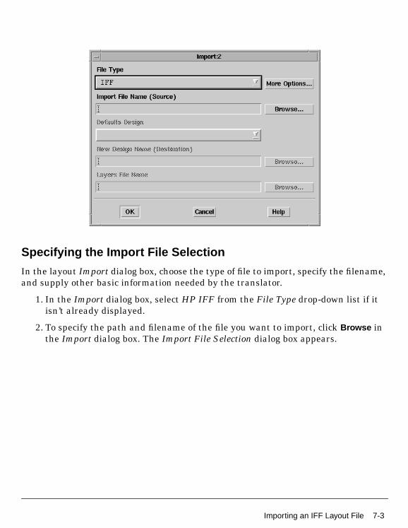
In the layout Import dialog box, choose the type of file to import, specify the filename,and supply other basic information needed by the translator.
1. In the Import dialog box, select HP IFF from the File Type drop-down list if itisn’t already displayed.
2. To specify the path and filename of the file you want to import, click Browse inthe Import dialog box. The Import File Selection dialog box appears.
Importing an IFF Layout File 7-3

Importing IFF Layout Files into ADS
3. Double-click as needed to locate the directory containing your IFF file in theDirectories field, then click the file in the Files field. Alternatively, you can enterthe full path and file name in the Selection field.
4. After selecting the design you want to import, click OK. You are returned to theImport dialog box and the selected filename appears in the field labeled ImportFile Name (Source).
5. Click More Options to define the import options. The Import HPIFF Optionsdialog box appears.
Selecting Import IFF Options
This section describes the choices available in the Import HPIFF Options dialog box.Import options for other file formats are detailed in the ADS “Importing andExporting Designs” manual.
To access the layout Import IFF Options dialog box from the Import dialog, click MoreOptions . The layout Import IFF Options dialog box appears.
7-4 Importing an IFF Layout File
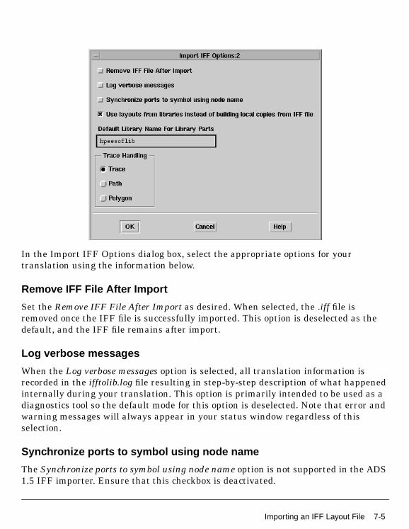
In the Import IFF Options dialog box, select the appropriate options for yourtranslation using the information below.
Remove IFF File After Import
Set the Remove IFF File After Import as desired. When selected, the .iff file isremoved once the IFF file is successfully imported. This option is deselected as thedefault, and the IFF file remains after import.
Log verbose messages
When the Log verbose messages option is selected, all translation information isrecorded in the ifftolib.log file resulting in step-by-step description of what happenedinternally during your translation. This option is primarily intended to be used as adiagnostics tool so the default mode for this option is deselected. Note that error andwarning messages will always appear in your status window regardless of thisselection.
Synchronize ports to symbol using node name
The Synchronize ports to symbol using node name option is not supported in the ADS1.5 IFF importer. Ensure that this checkbox is deactivated.
Importing an IFF Layout File 7-5
Importing IFF Layout Files into ADS
Default Library Name For Library Parts
When the IFF file does not specify a library name for a component that needs to becreated, the library name specified in this field is used. This is only necessary forenvironments that do not support the concept of a library. Mentor Graphics willalways provide a library name.
Use layouts from libraries instead of building local copies from IFF file
Layout IFF files contain all of the graphics primitives required to represent afootprint of a component. This is a historical requirement, dating back to when it wasnot possible to represent components parametrically in Mentor Graphics. When thisoption is not checked, all footprints and transmission line components will have newcomponents created for them in ADS. This will have the effect of flattening anyparametrically defined footprints/layouts (e.g. an MLIN component). Normally, thisoption should be checked. When checked, ADS will consult with the Library Browser,and get centrally defined layout definitions, including parameterized layoutdefinitions, for all footprints. If a definition cannot be found, the geometries in theIFF file will be used.
Trace Handling
ADS supports three different ways of interpreting metal lines, as a Trace, as a Path,or as a Polygon. This option allows you to specify how you wish to handle metal lines.Specifying trace means that there will be a connection point for the metal line oneach end, making the metal line similar to a microstrip element. Specifying a pathmeans that the metal line will be a path. Paths in ADS have a width, and are definedby points, but they do not have connectivity pins like a trace does. Specifying apolygon means the metal line will instead be created as a polygon.A polygon, like apath, also does not have any pins to define connectivity.
Note The Default Library Name For Library Parts field is identical to the field of thesame name in the Export IFF Options dialog box. Changes made to this field willmodify the contents of the field in the Export IFF Options dialog box. For moreinformation on Exporting IFF layout files, refer to “Exporting IFF Layout Files fromADS” on page 8-1.
7-6 Importing an IFF Layout File
About Component Libraries
A component library in Advanced Design System consists of a collection of componentdefinitions. Each primitive component has an associated component name, symboland predefined component parameters that include relevant physical and electricalcharacteristics.
The IFF translator can be used as the initial step in creating an ADS componentlibrary however; this topic is outside of the scope of this manual. Creating an ADScomponent library using IFF requires specialized tools and training. If you’reinterested in learning more about this topic, contact Agilent EEsof-EDA’s SolutionServices.
Completing the IFF Import
After specifying the IFF import options, click OK in the Import IFF Options dialog boxto save your settings or Cancel to retain the default settings. After clicking OK, youare returned to the Import dialog box. Click OK to begin the translation.
When translation is complete, an Information Message dialog box appears stating,IFF Import Completed. The IFF Import log window also appears. Review the logmessage searching for any error messages or warnings generated during export.
Importing an IFF Layout File 7-7

Importing IFF Layout Files into ADS
7-8 Importing an IFF Layout File
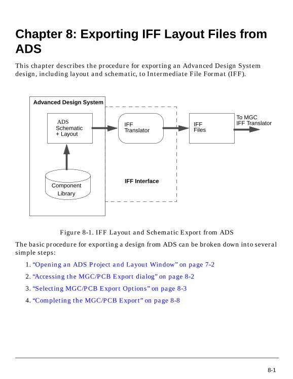
Chapter 8: Exporting IFF Layout Files fromADSThis chapter describes the procedure for exporting an Advanced Design Systemdesign, including layout and schematic, to Intermediate File Format (IFF).
Figure 8-1. IFF Layout and Schematic Export from ADS
The basic procedure for exporting a design from ADS can be broken down into severalsimple steps:
1. “Opening an ADS Project and Layout Window” on page 7-2
2. “Accessing the MGC/PCB Export dialog” on page 8-2
3. “Selecting MGC/PCB Export Options” on page 8-3
4. “Completing the MGC/PCB Export” on page 8-8
Schematic
Component
IFFIFFTranslator
Advanced Design System
IFF Interface
Files
To MGCIFF TranslatorADS
Library
+ Layout
8-1
Exporting IFF Layout Files from ADS
Exporting an IFF Layout FileThis section describes the procedure for exporting an IFF layout file from AdvancedDesign System using the MGC/PCB Translator’s User Interface. Before exporting anIFF layout file, refer to “Opening an ADS Project and Layout Window” on page 7-2.
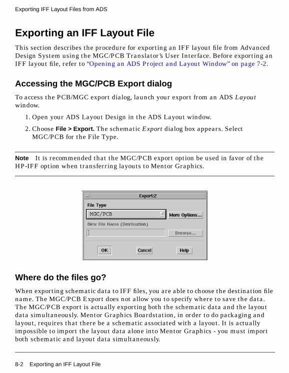
Accessing the MGC/PCB Export dialog
To access the PCB/MGC export dialog, launch your export from an ADS Layoutwindow.
1. Open your ADS Layout Design in the ADS Layout window.
2. Choose File > Export. The schematic Export dialog box appears. SelectMGC/PCB for the File Type.
Note It is recommended that the MGC/PCB export option be used in favor of theHP-IFF option when transferring layouts to Mentor Graphics.
Where do the files go?
When exporting schematic data to IFF files, you are able to choose the destination filename. The MGC/PCB Export does not allow you to specify where to save the data.The MGC/PCB export is actually exporting both the schematic data and the layoutdata simultaneously. Mentor Graphics Boardstation, in order to do packaging andlayout, requires that there be a schematic associated with a layout. It is actuallyimpossible to import the layout data alone into Mentor Graphics - you must importboth schematic and layout data simultaneously.
8-2 Exporting an IFF Layout File
Because both files are needed to do a successful import, the MGC/PCB export hardcodes the file names, so that they will be easily identified when you later choose toimport them into Mentor. In the project containing your design, a new directory,to_mgc, will be created. Within that directory, a directory will be created, called<design name>.hpxfer. Within that directory, there will be three files:
• design_info - contains optional user comments.
• layout.iff - contains the layout representation of the design.
• schematic.iff - contains the schematic representation of the design.
For example, if a design was created called demo, in the project directory, a newdirectory would be created called to_mgc. Within to_mgc, there would be a directorycalled demo.hpxfer. Within demo.hpxfer, there would be a file called design_info, a filecalled layout.iff, and a file called schematic.iff.
Selecting MGC/PCB Export Options
This section describes the choices available in the schematic MGC/PCB ExportOptions dialog box.
To access the MGC/PCB Export IFF Options dialog box from the Export dialog
1. Click More Options . The MGC/PCB Export IFF Options dialog box appears.
Exporting an IFF Layout File 8-3
Exporting IFF Layout Files from ADS
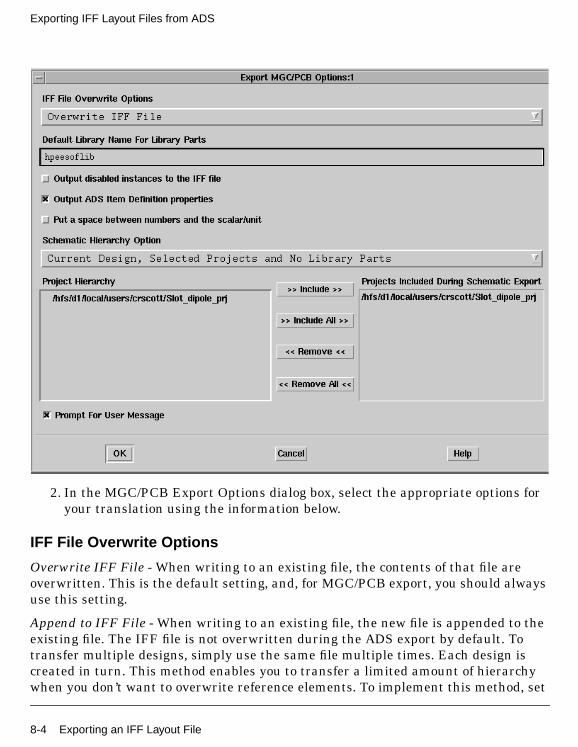
2. In the MGC/PCB Export Options dialog box, select the appropriate options foryour translation using the information below.
IFF File Overwrite Options
Overwrite IFF File - When writing to an existing file, the contents of that file areoverwritten. This is the default setting, and, for MGC/PCB export, you should alwaysuse this setting.
Append to IFF File - When writing to an existing file, the new file is appended to theexisting file. The IFF file is not overwritten during the ADS export by default. Totransfer multiple designs, simply use the same file multiple times. Each design iscreated in turn. This method enables you to transfer a limited amount of hierarchywhen you don’t want to overwrite reference elements. To implement this method, set
8-4 Exporting an IFF Layout File
the hierarchy level to None, then export one sub-network followed by the maindesign. No IFF data is generated for any of the referenced components in eitherdesign, so the only two circuits overwritten during an import are the two designstransferred.
Output disabled instances to the IFF file
When this option is selected, if an instance is disabled in the schematic, it will still beoutput into the IFF file. If the checkbox is deselected (default), disabled instances willnot be exported. This option can be utilized to omit certain components from beingtransferred to remote environments that might not support the components (e.g.disable the simulation components prior to creating an IFF file to send to MentorGraphics, which does not have any definitions for the simulator components).Activate this option if you want to get everything. Deactivate this option if you wantto filter out the unused/unwanted components.
Output ADS Item Definition properties
When this option is selected, ADS Item Definition properties are utilized to recreatethe information necessary to simulate a component for ADS. For example, if you haveparameters on a resistor, some Item Definition properties are created in the IFF file(e.g. R_ADS_UNIT=1), which allow the IFF importer to exactly recreate thecomponent as it exists in ADS. However, other tools will not recognize the ItemDefinition parameters, and may misinterpret the properties as being separate. Iflibrary symbols are being exported to other environments that do not recognize theADS Item Definition parameters, the option should be turned off. This option isdeselected by default.
Put a space between numbers and the scalar/unit
When this option is selected, parameter values are exported as they normally appearin ADS (i.e. with a space between the number and the scalar, e.g. “1 pF”). If thecheckbox is deactivated, the exporter converts the values into the IFF valuespecification, which is to have no space between a number and a scalar (e.g. "1pF").Ideally, an IFF exporter should interpret either form of number, and set the valueinternally to whatever is normal for that environment. Mentor Graphics does notinterpret the IFF property values in any way, and expects that the values from ADSwill have a space in them. The RF Architect ADS library is set up to expect values tohave a space between a number and a scalar/unit. If the space is not there, the ADS
Exporting an IFF Layout File 8-5
Exporting IFF Layout Files from ADS
components (e.g. MLIN) will not be placed properly. For an MGC/PCB transfer, thisoption should always be selected. This option is deselected by default.
Default Library Name for Library Parts
When the IFF file does not specify a library name for a component that needs to becreated, the library name specified in this field is used. This is necessary forenvironments that do not support the concept of a library.
Design objects are stored in a group that uses the same name as the project directory,but library parts are stored in either the default library hpeesoflib or a library thatyou specify. The default library name can contain only alpha numeric characters.
Note The Default Library Name For Library Parts field is identical to the field of thesame name in the Import IFF Options dialog box. Changes made to this field willmodify the contents of the field in the Import IFF Options dialog box.
About Component Libraries
A component library in ADS consists of a collection of component definitions. Eachprimitive component has an associated component name, symbol and predefinedcomponent parameters that include relevant physical and electrical characteristics.
The IFF Translator can be used as the initial step in creating an ADS componentlibrary however, this topic is outside of the scope of this manual. Creating an ADScomponent library using IFF requires specialized tools and training. If you’reinterested in learning more about this topic, contact Agilent EEsof-EDA’s SolutionServices.
Schematic Hierarchy Option
The Schematic Hierarchy Option drop-down list enables you to establish how much ofthe design hierarchy is exported:
Current Design Only Write current level only. Complete design information for thecurrent design is exported. Instance-specific information (parameter values andcoordinates identifying position) is also exported. Detailed definitions of areferenced design are not exported.
Current Design, Selected Projects and No Library Parts Complete designinformation for the current design is exported. Referenced designs that reside in a
8-6 Exporting an IFF Layout File
project selected for inclusion during export and are part of the current design’shierarchy are also exported. Library parts are not exported. This is the defaultsetting.
Current Design, Selected Projects and All Library Parts Complete designinformation for the current design is exported. Referenced designs that reside in aproject selected for inclusion during export and are part of the current design’shierarchy are also exported. In addition, library parts are exported.
Project Hierarchy
Displays the current project. If hierarchical, all included projects are listed in theappropriate order.
Projects Included During Schematic Export
This field contains the projects for which schematic design information is exported.You can customize this list if the current project is hierarchical.
To add a project to this list:
1. In the Project Hierarchy list, click the desired project.
2. Click the Include button. The project is added to the Projects Included list.
To include all projects, click Include All .
To remove a project from the Projects Included list:
1. In the Projects Included list, click the entry you want to remove.
2. Click the Remove button. The project is removed from the list.
To remove all entries from the Projects Included list, click Remove All .
This is an example of using the Project Hierarchy and Projects Included DuringSchematic Export fields. First you make a project called Proj_A that includes severaldesigns. Then you make another project called Proj_B and you want to reuse some ofthe designs from project Proj_A in project Proj_B. You can then include Proj_A inProj_B by using the Include button to have access to all the designs in Proj_A afteryour export is complete.
Exporting an IFF Layout File 8-7
Exporting IFF Layout Files from ADS
Prompt for User Message
This option is selected by default. If the option is selected, a dialog will be brought upprior to the export of the layout and schematic files. You may enter as much text intothis dialog as you want. The text will be stored in the design_info file that is createdthe to_mgc/<design>.hpxfer directory.
Completing the MGC/PCB Export
After specifying the export options, click OK in the MGC/PCB Export Options dialogbox to save your settings or Cancel to retain the default settings. After clicking OK,you are returned to the Export dialog box. Click OK to begin the translation.
When translation is complete, an Information Message dialog box appears stating,IFF Export Completed. The IFF Export log window also appears. Review the logmessage searching for any error messages or warnings generated during export.
8-8 Exporting an IFF Layout File
Index
AADS, 1-1Item Definition properties, 4-6, 8-5layout, 8-2projects, 3-2, 7-2schematic, 3-2, 4-2, 7-2
Ample, 2-3BBoardstation, 1-1, 1-2, 5-2, 6-2
IFF Read Dialog, 5-4Ccomponent libraries, 1-3, 1-6
translation, 1-6components
mapping, 2-4parameters, 2-4translating, 4-6, 8-5
constructing designs for IFF translation, 2-5coordinates, 4-8, 8-6Dda, 5-2, 6-2, 6-5da_lms, 5-2, 6-2, 6-5Design Architect, 1-1, 5-2
da, 5-2designs
design objects, 4-7, 8-6identical names, 3-2, 7-2referenced designs, 4-8, 8-6transferring multiple designs, 4-5, 8-4
diagnostics, 3-5, 7-5EEDA, 1-1error messages, 3-5, 6-4, 7-5export log, 6-4exporting layouts, 8-1exporting schematics, 4-1, 6-1Ffiles
file destination, 4-4file selection, 3-3, 4-2, 7-3
For, 5-2Hhelp, 2-5Hewlett Packard, 2-1hierarchical
designs, 2-5projects, 4-8, 8-7
hpeesoflib, 4-7, 8-6IIBM, 2-1IFF, 1-1
export options, 4-3, 8-3import options, 3-4, 7-4layout file, 7-2, 8-2schematic file, 3-2, 4-2, 6-1translation availability, 1-3translators, 1-2, 2-1use model, 1-4write dialog in design architect, 6-2write dialog in RF layout, 6-5
ifftolib.log, 3-5, 7-5importing
layouts, 7-1schematics, 3-1, 5-1
input transfer form, 5-2Llayout
ADS, 8-2hierarchy, 8-6import, 7-1layout per cellview, 2-6
librariescompatible component libraries, 1-6, 2-3, 2-4component library requirements, 2-3, 3-6, 7-7default library name, 4-7, 8-6library development, 2-5library name, 3-5, 4-7, 7-6, 8-6
licenses, 2-1log messages, 6-4MMentor, 2-1
Design Architect, 6-2, 6-5Mentor Graphics, 5-2
Mentor Graphics Corporation, 2-2supported versions, 2-1
Oopening
ADS project and schematic window, 3-2operating system versions, 2-1
Index-1
Pparameter
spacing, 4-6, 8-5values, 4-8, 8-6
partial translation, 1-6PCB/MGC export dialog, 8-2pcbrarch, 2-2pcbrflayout, 2-2projects
ADS, 3-2, 7-2hierarchical, 4-8, 8-7
RRF Architect, 2-2RF Layout, 2-2Sschematic
ADS, 3-2, 4-2, 7-2export, 6-1hierarchy, 4-7import, 3-1, 5-1schematics per cell, 2-6symbol per cellview, 2-6translation, 1-6, 2-5
settingenvironment for mentor graphics, 2-2
simulation, 2-4control elements, 2-5
software requirements, 2-1specialized tools, 1-6subcircuits, 2-5Sun, 2-1Tthird party frameworks, 1-3translation
schematic, 2-5Wwarning messages, 3-5, 6-4, 7-5
Index-2