Embed Size (px)
Citation preview
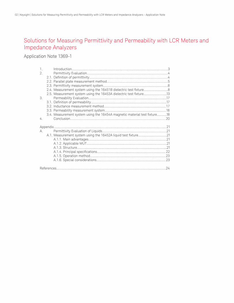
Keysight TechnologiesSolutions for Measuring Permittivity and Permeability with LCR Meters and Impedance Analyzers
Application Note
02 | Keysight | Solutions for Measuring Permittivity and Permeability with LCR Meters and Impedance Analyzers - Application Note
Solutions for Measuring Permittivity and Permeability with LCR Meters and Impedance Analyzers
1 Introduction32 Permittivity Evaluationhelliphelliphelliphelliphelliphelliphelliphelliphelliphelliphelliphelliphelliphelliphelliphelliphelliphelliphelliphelliphelliphelliphelliphelliphelliphelliphelliphelliphellip4 21 Definition of permittivityhelliphelliphelliphelliphelliphelliphelliphelliphelliphelliphelliphelliphelliphelliphelliphelliphelliphelliphelliphelliphelliphelliphelliphelliphelliphelliphelliphellip4 22 Parallel plate measurement methodhelliphelliphelliphelliphelliphelliphelliphelliphelliphelliphelliphelliphelliphelliphelliphelliphelliphelliphelliphelliphelliphellip5 23 Permittivity measurement systemhelliphelliphelliphelliphelliphelliphelliphelliphelliphelliphelliphelliphelliphelliphelliphelliphelliphelliphelliphelliphelliphelliphellip8 24 Measurement system using the 16451B dielectric test fixturehelliphelliphelliphelliphelliphelliphelliphellip8 25 Measurement system using the 16453A dielectric test fixturehelliphelliphelliphelliphelliphelliphelliphellip133 Permeability Evaluationhelliphelliphelliphelliphelliphelliphelliphelliphelliphelliphelliphelliphelliphelliphelliphelliphelliphelliphelliphelliphelliphelliphelliphelliphelliphelliphelliphellip17 31 Definition of permeabilityhelliphelliphelliphelliphelliphelliphelliphelliphelliphelliphelliphelliphelliphelliphelliphelliphelliphelliphelliphelliphelliphelliphelliphelliphelliphelliphellip17 32 Inductance measurement methodhelliphelliphelliphelliphelliphelliphelliphelliphelliphelliphelliphelliphelliphelliphelliphelliphelliphelliphelliphelliphelliphelliphellip17 33 Permeability measurement systemhelliphelliphelliphelliphelliphelliphelliphelliphelliphelliphelliphelliphelliphelliphelliphelliphelliphelliphelliphelliphelliphellip18 34 Measurement system using the 16454A magnetic material test fixturehelliphelliphellip184 Conclusionhelliphelliphelliphelliphelliphelliphelliphelliphelliphelliphelliphelliphelliphelliphelliphelliphelliphelliphelliphelliphelliphelliphelliphelliphelliphelliphelliphelliphelliphelliphelliphelliphelliphelliphellip20
Appendixhelliphelliphelliphelliphelliphelliphelliphelliphelliphelliphelliphelliphelliphelliphelliphelliphelliphelliphelliphelliphelliphelliphelliphelliphelliphelliphelliphelliphelliphelliphelliphelliphelliphelliphelliphelliphelliphelliphelliphelliphellip21A Permittivity Evaluation of Liquidshelliphelliphelliphelliphelliphelliphelliphelliphelliphelliphelliphelliphelliphelliphelliphelliphelliphelliphelliphelliphelliphelliphellip21 A1 Measurement system using the 16452A liquid test fixturehelliphelliphelliphelliphelliphelliphelliphelliphelliphellip21 A11 Main advantageshelliphelliphelliphelliphelliphelliphelliphelliphelliphelliphelliphelliphelliphelliphelliphelliphelliphelliphelliphelliphelliphelliphelliphelliphelliphelliphelliphellip21 A12 Applicable MUThelliphelliphelliphelliphelliphelliphelliphelliphelliphelliphelliphelliphelliphelliphelliphelliphelliphelliphelliphelliphelliphelliphelliphelliphelliphelliphelliphelliphellip21 A13 Structurehelliphelliphelliphelliphelliphelliphelliphelliphelliphelliphelliphelliphelliphelliphelliphelliphelliphelliphelliphelliphelliphelliphelliphelliphelliphelliphelliphelliphelliphelliphelliphelliphellip21 A14 Principal specificationshelliphelliphelliphelliphelliphelliphelliphelliphelliphelliphelliphelliphelliphelliphelliphelliphelliphelliphelliphelliphelliphelliphelliphelliphellip 22 A15 Operation methodhelliphelliphelliphelliphelliphelliphelliphelliphelliphelliphelliphelliphelliphelliphelliphelliphelliphelliphelliphelliphelliphelliphelliphelliphelliphelliphelliphellip23 A16 Special considerationshelliphelliphelliphelliphelliphelliphelliphelliphelliphelliphelliphelliphelliphelliphelliphelliphelliphelliphelliphelliphelliphelliphelliphelliphellip23
Referenceshelliphelliphelliphelliphelliphelliphelliphelliphelliphelliphelliphelliphelliphelliphelliphelliphelliphelliphelliphelliphelliphelliphelliphelliphelliphelliphelliphelliphelliphelliphelliphelliphelliphelliphelliphelliphelliphelliphelliphellip24
Application Note 1369-1
Table 1 Measurement technology and methods for permittivity and permeability parameters
Measurement parameter Measurement technology Measurement method
Impedance analysis Parallel plate
Permittivity S parameters
Cavity
Free space
Impedance analysis Inductance
Permeability Network analysis Reflection wave
S parameters
Cavity
1 Introduction
A material evaluation measurement system is comprised of three main pieces These elements include pre-cise measurement instruments test fixtures that hold the material under test and software that can calculate and display basic material parameters such as permittivity and permeability Various measurement methods for permittivity and permeability currently exist (see Table 1) However this notersquos primary focus will be on methods that employ impedance measurement technology which have the following advantages
ndash Wide frequency range from 20 Hz to 1 GHz
ndash High measurement accuracy ndash Simple preparations (fabrication
of material measurement setup) for measurement
This note begins by describing measurement methods systems and solutions for permittivity in Section 2 followed by permeability in Section 3 The resistivity measurement system and the permittivity measurement system for liquids are described later in the appendix
Recently electronic equipment technology has dramatically evolved to the point where an electronic componentrsquos material characteristics becomes a key factor in a circuitrsquos behavior For example in the manufacture of high capacitance multi-layer ceramic capacitors (ML-CCs) which are being used more in digital (media) appliances employing high κ (dielectric constant) material is required In addition various electri-cal performance evaluations such as frequency and temperature response must be performed before the materials are selected
In fields outside of electronic equipment evaluating the electri-cal characteristics of materials has become increasingly popular This is because composition and chemical variations of materials such as solids and liquids can adopt electrical characteristic responses as substituting performance parameters
04 | Keysight | Solutions for Measuring Permittivity and Permeability with LCR Meters and Impedance Analyzers - Application Note
2 Permittivity Evaluation
When complex permittivity is drawn as a simple vector diagram as shown in Figure 1 the real and imaginary components are 90deg out of phase The vector sum forms an angle δ with the real axis (εracute) The tangent of this angle tan δ or loss tangent is usually used to express the relative ldquolossinessrdquo of a
κ = εr = ε
εr
ε0
εε0
εrεr
= εr εε0
jj εr =(Real part)
(Real)
(Imaginary part)
(Imaginary)
tan δ =
tan δ = D (Dissibation factor)
κ = εr =ε0 =
Dielectic constant
Complex relative permitivity Permitivity of
free space1
36π X 10-9 [Fm]
δ
εr
εr
- -
material The term ldquodielectric constantrdquo is often called ldquopermittivityrdquo in techni-cal literature In this application note the term permittivity will be used to refer to dielectric constant and complex relative permittivity
Figure 1 Definition of relative complex permittivity (εr)
Permittivity describes the interaction of a material with an electric field The principal equations are shown in Figure 1 Dielectric constant (κ) is equivalent to the complex relative permittivity (εr) or the complex permittivity (ε) relative to the permittivity of free space (ε0) The real part of complex relative permittivity (εracute) is a measure of how much energy from an external field is stored in a material εracute gt 1 for most solids and liquids The imaginary part of complex relative permittivity (εracute) is called the loss factor and is a measure of how dissipative or lossy a material is to an external field εracute is always gt 0 and is usually much smaller than εracute The loss factor includes the effects of both dielectric loss and conductivity
21 Definition of permittivity
05 | Keysight | Solutions for Measuring Permittivity and Permeability with LCR Meters and Impedance Analyzers - Application Note
When using an impedance-measuring instrument to measure permittivity the parallel plate method is usually employed An overview of the parallel plate method is shown in Figure 2
The parallel plate method also called the three terminal method in ASTM D150 involves sandwiching a thin sheet of material or liquid between two electrodes to form a capacitor (Note Throughout the remainder of this document materials under test whether the material is a solid or a liquid will be referred to as MUT) The measured capacitance is then used to calculate permittivity In an actual test setup two electrodes are configured with a test fixture sandwiching dielectric material The impedance-measuring instrument would measure vector components of capacitance (C) and dissipation (D) and a software program would calculate permittivity and loss tangent
The flow of the electrical field in an actual measurement is shown in Figure 3 When simply measuring the dielectric material between two electrodes stray capacitance or edge capacitance is formed on the edges of the electrodes and consequently the measured capacitance is larger than the capacitance of the dielectric material The edge capacitance causes a measurement error since the current flows through the dielectric material and edge capacitor
A solution to the measurement error caused by edge capacitance is to use the guard electrode The guard electrode absorbs the electric field at the edge and the capacitance that is measured between the electrodes is only composed of the current that flows through the dielectric material Therefore accurate measurements are possible When the main electrode is used with a guard electrode the main electrode is called the guarded electrode
Figure 2 Parallel plate method
= ( ndash j )
Electrodes (Area = A)Equivalent
circuit
Cp G
Solidthickness = t Liquid
Y = G + jωCp
= jωCo ( ndash j )Co Air capacitance
CpCo
GωCo
CpCo
GωCo
t CpA εo
= ( )
εr
εr
εrt
ω Rp A εo= ( )
Figure 3 Effect of guard electrode
Edge capacitance (stray) Guard electrodes
Electrical fieldElectrical field+
-
+
-
22 Parallel plate measurement method of measuring permittivity
06 | Keysight | Solutions for Measuring Permittivity and Permeability with LCR Meters and Impedance Analyzers - Application Note
Contacting electrode meth-od
This method derives permittivity by measuring the capacitance of the electrodes contacting the MUT directly (see Figure 4) Permittivity and loss tangent are calculated using the equations below
Cp Equivalent parallel capacitance of MUT [F]D Dissipation factor (measured value)tm Average thickness of MUT [m]A Guarded electrodersquos surface area[m2]d Guarded electrodersquos diameter[m]ε0 Permittivity of free space = 8854 x 10-12 [Fm] Equations
tan δ = D
The contacting electrode method requires no material preparation and the operation involved when measuring is simple Therefore it is the most widely used method However a significant measurement error can occur if airgap and its effects are not considered when using this method
When contacting the MUT directly with the electrodes an airgap is formed between the MUT and the electrodes No matter how flat and parallel both sides of the MUT are fabricated an airgap will still form
This airgap is the cause for measurement error because the measured capacitance will be the series connection of the capacitance of the dielectric material and the airgap The relationship between the airgaprsquos thickness and measurement error is determined by the equation shown in Figure 5
An extra step is required for material preparation (fabricating a thin film electrode) but the most accurate measurements can be performed
Figure 5 Airgap effects
Capacitance of airgap
Capacitance of dielectric materialtm ta
Measured capacitance
Measured errordue to airgap
Co = εo
Cx = εx εo
= εerr εo
Ata
Atm
Atm + ta1
Co
εerrεx
1Cx
tmta
Cerr = +
1- = εx - 1εx +
1
Figure 4 Contacting electrode method
εr= =
t x CA x εm p t x Cm p
0 π d2
2
0 x ε
t MUT
d
m
g
Unguarded electrode
Guarded electrode
Guard electrode
Measurement error is a function of the relative permittivity (εracute) of the MUT thickness of the MUT (tm) and the airgaprsquos thickness (ta) Sample results of measurement error have been calculated in Table 2 Notice that the effect is greater with thin materials and high κ materials
This airgap effect can be eliminated by applying thin film electrodes to the surfaces of the dielectric material
εrrsquoTable 2 Measurement error caused by airgap
ta tm 2 5 10 20 50 100
0001 01 04 1 2 5 90005 05 2 4 9 20 33001 1 4 8 16 33 50005 5 16 30 48 70 8301 8 27 45 63 82 90
07 | Keysight | Solutions for Measuring Permittivity and Permeability with LCR Meters and Impedance Analyzers - Application Note
Non-contacting electrode method
This method was conceptualized to incorporate the advantages and exclude the disadvantages of the contacting electrode method It does not require thin film electrodes but still solves the airgap effect Per-mittivity is derived by using the results of two capacitance measurements obtained with the MUT and without it (Figure 6)
Theoretically the electrode gap (tg) should be a little bit larger than the thickness of the MUT (tm) In other words the airgap (tg ndash tm) should be extremely small when compared to the thickness of the MUT (tm) These requirements are necessary for the measurement to be performed appropriately Two capacitance measurements are necessary and the results are used to calculate permittivity The equation is shown at right
Cs1 Capacitance without MUT inserted[F] Cs2 Capacitance with MUT inserted[F]D1 Dissipation factor without MUT inserted D2 Dissipation factor with MUT inserted tg Gap between guardedguard electrode and unguarded electrode [m]tm Average thickness of MUT [m]
Equations
εr
= t g
t m
Cs1
1
1minus1minusCs2
minus1
x
t g
t mtan δ = D2 + εr x (D2 minus D1) x (when tan δ ltlt1)
Figure 6 Non-contacting electrode method
d g
tm
MUT
tg
Unguarded electrode
Guard electrodeGuarded electrode
Table 3 Comparison of parallel plate measurement methods
Method Contacting electrode (without thin film electrode)
Non-contacting electrode Contacting electrode (with thin film electrode)
Accuracy LOW MEDIUM HIGH
Application MUT Solid material with a flat and smooth surface
Solid material with a flat and smooth surface
Thin film electrode must be applied onto surfaces
Operation 1 measurement 2 measurements 1 measurement
08 | Keysight | Solutions for Measuring Permittivity and Permeability with LCR Meters and Impedance Analyzers - Application Note
23 Permittivity measurement system
Two measurement systems that employ the parallel plate method will be discussed here The first is the 16451B dielectric test fixture which has capabilities to measure solid materials up to 30 MHz The latter is the 16453A dielectric material test fix-ture which has capabilities to measure solid materials up to 1 GHz Details of measurement systems described in this note will follow the subheadings outlined below 1) Main advantages2) Applicable MUT3) Structure 4) Principal specifications5) Operation method6) Special considerations7) Sample measurements
24 Measurement system using the 16451B dielectric test fixture
241 Main advantages
ndash Precise measurements are possi-ble in the frequency range up to 30 MHz
ndash Four electrodes (A to D) are provided to accommodate the contacting and non-contacting electrode methods and various MUT sizes
ndash Guard electrode to eliminate the effect of edge capacitance
ndash Attachment simplifies open and short compensation
ndash Can be used with any imped-ance-measuring instrument with a 4-terminal pair configuration
Applicable measurement instruments E4990A 4285A E4980A and E4981A
09 | Keysight | Solutions for Measuring Permittivity and Permeability with LCR Meters and Impedance Analyzers - Application Note
242 Applicable MUT
The applicable dielectric material is a solid sheet that is smooth and has equal thickness from one end to the other The applicable dielectric materialrsquos size is determined by the measurement method and type of electrode to be used Electrodes A and B are used for the contacting electrode method without the fabrication of thin film electrodes Electrodes C and D are used for the contacting electrode method with the fabrication of thin film electrodes When employing the non-contacting electrode method electrodes A and B are used In this method it is recommended to process the dielectric material to a thickness of a few millimeters
The difference between electrodes A and B is the diameter (the same difference applies to electrodes C and D) Electrodes A and C are adapted for large MUT sizes and electrodes B and D are adapted for smaller MUT sizes The applicable MUT sizes for each electrode are shown in Tables 4 and 5 The dimensions of each electrode are shown in Figures 7 through 10
Table 4 Applicable MUT sizes for electrodes A and B
Table 5 Applicable MUT sizes for electrodes C and D
Figure 7 Electrode A dimensions Figure 8 Electrode B dimensions
Figure 9 Electrode C dimensions Figure 10 Electrode D dimensions
Electrode type Material diameter Material thickness Electrode diameter A 40mmto56mm tle10mm 38mm B 10mmto56mm tle10mm 5mm
Electrode type Material diameter Material thickness Electrode diameter C 56mm tle10mm 5to50mm D 20mmto56mm tle10mm 5to14mm
empty56empty52
empty7
Electrode-C
Test material
le 10
56Note empty signifies diameter Dimensions are in millimeters
Guard thin film electrode
Guarded thin film electrode
5 to 50
le 52The gap width shall be as small as practical
empty20empty16
empty7
Electrode-D
Test material
le 10
20 to 50Note empty signifies diameter Dimensions are in millimeters
5 to 14
le 16The gap width shall be as small as practical
empty56
empty38 02
Electrode-A
Test material
le 10
40 to 56Note empty signifies diameter Dimensions are in millimeters
empty20
empty5013
Electrode-B
Test material
le 10
10 to 56Note empty signifies diameter Dimensions are in millimeters
10 | Keysight | Solutions for Measuring Permittivity and Permeability with LCR Meters and Impedance Analyzers - Application Note
243 Structure
In order to eliminate the measurement error caused by edge capacitance a three-terminal configuration (including a guard terminal) is employed The struc-ture of the 16451B is shown in Figure 11
The electrodes in the 16451B are made up of the following
1 Unguarded electrode which is connected to the measurement instrumentrsquos high terminal 2 Guarded electrode which is connected to the measurement instrumentrsquos low terminal 3 Guard electrode which is connected to the measurement instrumentrsquos guard terminal (the outer conductor of the BNC connectors)
The guard electrode encompasses the guarded (or main) electrode and absorbs the electric field at the edge of the electrodes making accurate permittivity measurements possible
244 Principal specifications
The principal specifications are shown in Table 6 Figures 12 and 13 show the measurement accuracy when Keysightrsquos E4990A is used Further details about the measurement accuracy can be obtained from the Accessories Selection Guide for Impedance Measurements (literature number 5965-4792E)
Figure 11 Structure of the 16451B
Table 6 Principal specifications of the 16451B
Figure 12 Permittivity measurement accuracy (supplemental data)
Figure 13 Loss tangent measurement accuracy (supplemental data)
Unguarded electrodeGuard terminal
Guarded electrode
HcurHpotLputLcur
4-terminalpair
50454035302520151050
40 100 1 k 10 k 100 k 1 M 10 M 30 M
Electrode A
Frequency [Hz]
t = 1 [mm]Δ
ε r
ε
r [
]
er = 50er = 20er = 10er = 5er = 2
10
1
01
001
000140 100 1 k 10 k 100 k 1 M 10 M 30 M
Electrode A
Frequency [Hz]
t = 1 [mm]
tan
δ er
ror (
E a)
er = 50er = 20er = 10er = 5er = 2
When using the 4285A or E4990A above 5 MHz it is necessary to perform load compensation in addition to open and short compensation For more details please refer to Section 245 Operation method
Frequency le30MHzMax voltage plusmn42 VOperation temperature 0 degC to 55 degCTerminal configuration 4-terminal pair BNCCable length 1 mCompensation Openshort
11 | Keysight | Solutions for Measuring Permittivity and Permeability with LCR Meters and Impedance Analyzers - Application Note
245 Operation method
Figure 14 displays the flowchart when using the 16451B for permittivity mea-surements Each step in the flowchart is described here
Step 1 Prepare the dielectric material Fabricate the MUT to the appropriate size Use Figures 7 through 10 as references If the contacting electrode method with thin film electrodes is employed apply thin film electrodes to the surfaces of the MUT
Step 2 Attach the guarded electrode Select the appropriate electrode and fit it into the 16451B
Step 3 Connect the 16451B Connect the 16451B to the unknown terminals of the measurement instrument
Step 4 Cable length compensation Set the measurement instrumentrsquos cable length compensation function to 1 m Refer to the measurement instrumentrsquos operation manual for the setting procedure
Step 5 Compensate the residual impedance of the 16451B Use the furnished attachment to perform open and short compensation at a specified frequency This is necessary before adjusting the guarded and unguard-ed electrodes to be parallel to each other
Step 6 Adjust the electrodes To en-hance the measurement performance a mechanism is provided to adjust the guarded and unguarded electrodes to be parallel to each other By perform-ing this adjustment the occurrence of the airgap when using the contacting electrode method is minimized and an airgap with uniform thickness is created when using the non-contacting electrode method The adjustment procedure is discussed in the operation manual of the 16451B
Step 7 Set the measurement condi-tions Measurement conditions such as frequency and test voltage level are set on the measurement instru-ment Refer to the measurement instrumentrsquos operation manual for the setting procedure
Step 8 Compensate the residual impedance of the 16451B Use the furnished attachment to perform open and short compensation of the measurement conditions set in Step 7
When using the Keysight 4285A or E4990A above 5 MHz it is necessary to perform load compensation also This is because for high frequency measurements it is difficult to disregard the residual impedance which cannot be removed by open and short compensation
In order to compensate the frequency response of the 16451B a measured value at 100 kHz is used as a standard value and load compensation is performed at high frequencies The air capacitance formed by creating an airgap between the electrodes (with nothing inserted) is adopted as the load device for the 16451B Table 7 lists the recommended capacitance values that are obtained by adjusting the height of the airgap between the electrodes It is assumed that the air capacitance has no frequency depen-dency no loss and has a flat response The capacitance value (Cp) at 100 kHz (G is assumed to be zero) is used for load compensation
Step 9 Insert MUT Insert the MUT between the electrodes
Step 10 Cp-D measurement The ca-pacitance (Cp) and dissipation factor (D) is measured When employing the non-contacting electrode method two Cp-D measurements are performed with and without the MUT
Step 11 Calculate permittivity As previously discussed in Section 22 use the appropriate equation to calculate permittivity
Table 7 Load values
Measured Cp value at 100 kHz
Figure 14 Measurement procedure flowchart for the 16451B
START
END
1 Prepare the dielectric material
2 Attach the guarded electrode
3 Connect the 16451B
4 Cable length compensation
6 Adjust the electrodes
7 Set the measurement conditions
9 Insert the MUT
10 Cp-D measurement
11 Calculate permittivity
8 Compensate the residual impedance
5 Compensation for adjustment of electrodes
Electrode Recommended capacitance A 50 pF plusmn 05 pF B 5 pF plusmn 005 pF C D 15 pF plusmn 005 pF
12 | Keysight | Solutions for Measuring Permittivity and Permeability with LCR Meters and Impedance Analyzers - Application Note
246 Special considerations
As mentioned before to reduce the effect of the airgap which occurs between the MUT and the electrodes it is practical to employ the contacting electrode method with thin film electrodes (Refer to Section 22) Elec-trodes C and D are provided with the 16451B to carry out this method
Materials under test that transform under applied pressure cannot keep a fixed thickness This type of MUT is not suitable for the contacting electrode method Instead the non-contacting method should be employed
When the non-contacting method is employed the electrode gap tg is required to be at most 10 larger than the thickness of the MUT It is extreme-ly difficult to create a 10 electrode gap with thin film materials Therefore it is recommended that only materials thicker than a few millimeters be used with this method
The micrometer on the 16451B is designed to make a precise gap when using the non-contacting electrode method Accurate measurements of the thickness of MUT cannot be made when employing the contacting electrode method This is because the micrometer scale is very dependent upon the guard and the unguarded electrodes being parallel Using a separate micrometer for measuring thickness is recommended
13 | Keysight | Solutions for Measuring Permittivity and Permeability with LCR Meters and Impedance Analyzers - Application Note
25 Measurement system using the 16453A dielectric material test fixture
251 Main advantages
ndash Wide frequency range from 1 MHz ndash 1 GHz
ndash Option E4991B-002 (material measurement software) internal firmware in the E4991B solves edge capacitance effect
ndash Open short and load compensation
ndash Direct readouts of complex permittivity are possible with the Option E4991B-002 (material measurement software) internal firmware in the E4991B
ndash Temperature characteristics measurements are possible from ndash55 degC to +150 degC (with Options E4991B-002 and E4991B-007)
Figure 15 Applicable MUT size
Figure 16 Structure of the 16453A
d
t
t
d ge 15 mm03 mm le t le 3 mm
16453A
Upper electrode
Lower electrode
spring Diameteris 10 mm
MUT
Diameteris 7 mm
For temperature-response evaluation Option E4991B-007 temperature characteristic test kit is required A Microsoft Excel VBA sample program is pre-installed in the E4991B that provides chamber control and measurement setup functions The sample program can be copied to an external PC
Applicable measurement instruments E4991B (Option E4991B-002)
252 Applicable MUT
The applicable dielectric material is a solid sheet that is smooth and has equal thickness from one end to the other The applicable MUT size is shown in Figure 15
253 Structure The structure of the 16453A can be viewed in Figure 16 The upper electrode has an internal spring which allows the MUT to be fastened between the electrodes Applied pressure can be adjusted as well
The 16453A is not equipped with a guard electrode like the 16451B This is because a guard electrode at high frequency only causes greater residual impedance and poor frequency characteristics To lessen the effect of edge capacitance a correction function based on simulation results is used in the E4991B Option E4991B-002 (material measurement) firmware
Also residual impedance which is a major cause for measurement error cannot be entirely removed by open and short compensation This is why PTFE is provided as a load compensation device
14 | Keysight | Solutions for Measuring Permittivity and Permeability with LCR Meters and Impedance Analyzers - Application Note
The principal specifications are shown in Table 8 Figures 17 and 18 show the measurement accuracy when the E4991B is used Further details about the measurement accuracy can be obtained from the operation manual supplied with the instrument
255 Operation method
Figure 19 displays the flowchart when using the 16453A and E4991B for permittivity measurements The steps in the flowchart are described here For further details please refer to the Quick Start Guide for the E4991B
Figure 18 Loss tangent measurement accuracy (supplemental data)
Figure 17 Permittivity measurement accuracy (supplemental data)
Table 8 Principal specifications of the 16453A
Must be accompanied by the E4991B with Options E4991B-002 and E4991B-007
START
END
1 Select the measurement mode
2 Input thickness of MUT
3 Set the measurement conditions
4 Connect the 16453A
5 Input thickness of load device
6 Calibrate the measurement plane
8 Measure the MUT
7 Insert the MUT
Frequency 1MHzto1GHz Max voltage plusmn42 V Operating temperature -55 degC to +150 degC
Terminal configuration 7 mm Compensation Open short and load
Figure 19 Measurement procedure flowchart for the 16453A
Step 1 Select the measurement mode Select permittivity measurement in E4991Brsquos utility menu
Step 2 Input the thickness of MUT Enter the thickness of the MUT into the E4991B Use a micrometer to measure the thickness
Step 3 Set the measurement conditions of the E4991B Measurement conditions such as frequency test voltage level and measurement parameter are set on the measurement instrument
Step 4 Connect the 16453A Connect the 16453A to the 7 mm terminal of the E4991B
Step 5 Input the thickness of load device Before compensation enter the furnished load devicersquos (PTFE board) thickness into the E4991B
Step 6 Calibrate the measurement plane Perform open short and load calibration
Step 7 Insert MUT Insert the MUT between the electrodes
Step 8 Measure the MUT The measurement result will appear on the display The data can be analyzed using the marker functions
254 Principal specifications
15 | Keysight | Solutions for Measuring Permittivity and Permeability with LCR Meters and Impedance Analyzers - Application Note
256 Special considerations
As with the previous measurement system an airgap which is formed between the MUT and the electrodes can be a primary cause of measurement error Thin materials and high k materials are most prone to this effect Materials with rough surfaces (Figure 20) can be similarly affected by airgap
There is a technique to apply a thin film electrode onto the surfaces of the dielectric material in order to eliminate the airgap that occurs between the MUT and the electrodes This technique is shown in Figure 21 and 22 An electrode the exact shape and size to fit the 16453A is fabricated onto the dielectric material using either high-conductivity silver pastes or fired-on silver The MUT should be shaped as in Figure 21 with the thin film electrode thinner than the dielectric material In this case it is vital to appropriately position the fabricated thin film electrode onto the MUT to precisely contact the electrodes of the 16453A (Figure 22) Following this process will ensure a more accurate and reliable measurement
In addition if the MUTs are very thin for example close to 100 microm it is possible to stack 3 or 4 other MUTs and then make the measurement This will reduce the airgap and increase mea-surement precision The MUT must be smooth and not transform under applied pressure
Figure 20 Rough-surfaced dielectric material
Figure 22 Positioning of the fabricated thin film on the MUT
Figure 21 Fabricated thin film electrodersquos size
613
245
9999 25170
251
φ 7Cut-out for the positioning of the thin film electrode
Back
Unit mm
Electrode
Electrode
t1
t1
t 2
t 2 gt
Dielectricmaterial
φ 10
φ 2Front
Electrode
Electrode
MUT
Airgap
Another point to consider is the adjusting mechanism of the upper electrodersquos spring pressure The springrsquos pressure should be as strong as possible in order to minimize the occurrence of the airgap between the MUT and the electrodes However MUTs which transform under extreme pressure cannot be measured correctly since the thickness is affected To achieve stable measurements the spring pressure should be set at a level that does not transform the MUT
16 | Keysight | Solutions for Measuring Permittivity and Permeability with LCR Meters and Impedance Analyzers - Application Note
257 Sample measurements
As shown in Figure 23 a measurement result for glass epoxy frequency char-acteristic can be obtained by using the E4991B with the 16453A
Figure 23 Frequency response of glass epoxy (εr = 45)
17 | Keysight | Solutions for Measuring Permittivity and Permeability with LCR Meters and Impedance Analyzers - Application Note
31 Definition of permeability
Permeability describes the interaction of a material with a magnetic field It is the ratio of induction B to the applied magnetizing field H Complex relative permeability (micror) consists of the real part (microrrsquo) that represents the energy storage term and the imaginary part (microrrdquo) that represents the power dissipation term It is also the complex permeability (micro) relative to the permeability of free space (micro0) as shown in Figure 24
The inefficiency of magnetic material is expressed using the loss tangent tan δ The tan δ is the ratio of (microrrdquo) to (microrrsquo) The term ldquocomplex relative permeabilityrdquo is simply called ldquopermeabilityrdquo in technical literature In this application note the term permeability will be used to refer to complex relative permeability
32 Inductance measurement method
Relative permeability of magnetic material derived from the self-inductance of a cored inductor that has a closed loop (such as the toroidal core) is often called effective permeability The conventional method of measuring effective permeability is to wind some wire around the core and evaluate the inductance with re-spect to the ends of the wire This type of measurement is usually performed with an impedance measuring instrument Effective permeability is derived from the inductance measurement result using the following equations
Reff Equivalent resistance of magnetic core loss including wire resistance Leff Inductance of toroidal coilRw Resistance of wire only Lw Inductance of air-core coil inductanceN Turns
Average magnetic path length of toroidal core [m]A Cross-sectional area of toroidal core [m2]ω 2π f (frequency)micro0 4π x 10-7 [Hm]
Depending on the applied magnetic field and where the measurement is located on the hysteresis curve permeability can be classified in degree categories such as initial or maximum Initial permeability is the most commonly used parameter among manufacturers because most industrial applications involving magnetic material use low power levels
This application note focuses on effec-tive permeability and initial permeability derived from the inductance measurement method
Figure 25 Method of measuring effective permeability
Figure 24 Definition of complex permeability (m)
μr = μ
μ0
μμ0
= μr μμ0
- j j μr =(real part) (imaginary part)
μr
μrμr (real)
(imaginary)tan δ =
μr =μ =
μ0 =
Complex relative permeability
Permeability offree space 4π X 10-7 [Hm]
δ
μr
μr
BH
B
H
-
Equivalentcircuit
Lw Rw
Leff Reff
μμ
e
=
L
N 2 A
eff
0
μ
μe =
( R ndash R )
N 2 ω A
eff w
0
Some manufacturers use initial permeability even for magnetic materials that are employed at high power levels
3 Permeability Evaluation
18 | Keysight | Solutions for Measuring Permittivity and Permeability with LCR Meters and Impedance Analyzers - Application Note
33 Permeability measurement system The next section demonstrates a permeability measurement system using the 16454A magnetic material test fixture
34 Measurement system using the 16454A magnetic material test fixture
341 Main advantages
ndash Wide frequency range from 1 kHz to 1 GHz
ndash Simple measurements without needing a wire wound around the toroid
ndash Two fixture assemblies are ndash provided for different MUT sizes ndash Direct readouts of complex
permeability are possible with the E4991B (Option E4991B-002 material measurement software) or with the E4990A
Applicable instruments E4991B (Option E4991B-002) E4990A and 42942A
Figure 27 Structure of the 16454A and measurement concept
For temperature-response evaluation Option E4991B-007 temperature characteristic test kit is required A Microsoft Excel VBA sample program is pre-installed in the E4991B that provides chamber control and measurement setup functions The sample program can be copied to an external PC The E4990A does not have a high temperature test head
le 8 mm le 20 mm
Small size Large size
ge 5 mmge 31 mm
le 85 mmle 3 mm
Figure 26 Applicable MUT size
c b
E4991BE4990A
2πjωmicro0 h ln b
c + 1
Zm Measured impedance with toroidal core
micro
micro0
b ch
Permeability of free spaceHeight of MUT (material under test)Outer diameter of MUTInner diameter of MUT
Relative permeability
Zsm Measured impedance without toroidal core
bull
micro =bull
bull
(Zmbull
bull
Zsm)bull
minus
ndash Temperature characteristic measurements are possible from ndash55 degC to +150 degC (with the E4991B Options E4991B-002 and bE4991B-007)
342 Applicable MUT
The applicable magnetic material can only be a toroidal core The applicable MUT size is shown in Figure 26
343 Structure
The structure of the 16454A and the measurement concept are shown in Figure 27 When a toroidal core is in-serted into the 16454A an ideal
single-turn inductor with no flux leak-age is formed Permeability is derived from the inductance of the toroidal core with the fixture
19 | Keysight | Solutions for Measuring Permittivity and Permeability with LCR Meters and Impedance Analyzers - Application Note
344 Principal specifications
Principal specifications of the 16454A are shown in Table 9 above Figures 28 and 29 show the measurement accuracy when either the E4991B or the E4990A are used
345 Operation method
Figure 30 displays the flowchart when using the 16454A for permeability measurements Each step of the flowchart is described here
Step 1 Calibrate the measurement instrument When using the E4991B calibrate at the 7 mm terminal When using the E4990A perform SETUP on the 7 mm terminal of the 42942A Step 2 Connect the 16454A Connect the 16454A to the measurement in-strumentrsquos 7 mm terminal When using the E4991B select the permeability measurement mode
Step 3 Compensate the residual impedance of the 16454A Insert only the MUT holder and perform short compensation
Step 4 Input size of MUT Enter the size of the MUT into the measurement instrumentrsquos menu Use a micrometer to measure the size
Step 5 Insert MUT Insert the MUT with the holder into the 16454A
Step 6 Set the measurement condi-tions Measurement conditions such as frequency test signal level and measurement parameter are set on the measurement instrument
3000
2500
2000
2500
1000
500
01k 10k 100k 1M 10M 10M 1G
5
Frequency [Hz]
10
10
20
20
h In = 10 [mm]C b
μr
h In = 10 [mm]C b
100 E+01
100 E+00
00 E+00
00 E+00
00 E+00
tan δ
error
(Ea)
1k 10k 100k 1M 10M 100M 1GFrequency [Hz]
μr =3000
μr =1000
μr =300 μr =100
μr =30
μr =10
μr =3
START
END
1 Calibrate the instrument
2 Connect the 16454A
3 Compensate the residual impedance
4 Input the size of the MUT
5 Insert the MUT
6 Set the measurement conditions
7 Measure the MUT
Table 9 Principal specifications of the 16454A
Figure 28 Permeability measurement accuracy (supplemental data)
Figure 29 Loss tangent measurement accuracy (supplemental data)
Figure 30 Measurement procedure flowchart for the 16454A
Frequency 1kHzto1GHzMax dc bias current plusmn500 mAOperating temperature -55 degC to +150 degCTerminal configuration 7 mmCompensation Short
Step 7 Measure the MUT The measurement result will appear on the display The data can be analyzed using the marker functions
Internal firmware comes standard with the material measurement func-tion when using the E4991B (Option E4991B-002) For more details refer to the Operation Manual of the E4991B
20 | Keysight | Solutions for Measuring Permittivity and Permeability with LCR Meters and Impedance Analyzers - Application Note
346 Special considerations
When measuring a magnetic material with a high permittivity (near 10 or above) precise measurements cannot be performed near 1 GHz Permeability is derived from the inductance value of the combined impedance of the MUT and the fixture The measured impedance should be composed of inductance and a negligible amount of capacitance When the magnetic materialrsquos permittivity is high current flows through the space between the MUT and the fixture This is equivalent to a capacitor connected in parallel to the inductor (of the MUT) This parallel LC circuit causes an impedance-res-onance at a destined frequency The higher the permittivity the lower the resonant frequency will be and precise measurements will be difficult
347 Sample measurements
Frequency characteristic measurement results of a ferrite core are shown in Figure 31 The E4991B and the 16454A were used to obtain the results in Figure 31
4 Conclusion
In this application note permittivity and permeability measurement meth-ods using impedance measurement technology were discussed
The discussions covered various test fixturesrsquo structures applicable MUT sizes operation methods and special considerations By using this application note as a reference a measurement solution that satisfies measurement needs and conditions can be selected easily
Figure 31 Frequency response of ferrite core (μr = 120)
21 | Keysight | Solutions for Measuring Permittivity and Permeability with LCR Meters and Impedance Analyzers - Application Note
Appendix
A Permittivity Evaluation of Liquids
Permittivity measurements are often used for evaluation of liquid characteristics Permittivity measurements do not change the liquid physically and can be conducted rather simply and quickly As a result they are utilized in a wide array of research areas Here the 16452A liquid test fixture which employs the parallel plate method will be discussed as a permittivity measurement system for liquids
A1 Measurement system using the 16452A liquid test fixture
A11 Main advantages
ndash Wide frequency range from 20 Hz to 30 MHz
ndash Plastic resins oil-based chemical products and more can be measured
ndash Measurement is possible with a small volume of test liquid so MUT is not wasted
ndash Temperature characteristic measurements are possible from ndash20 degC to +125 degC
ndash Can be used with any impedance measuring instrument that has a 4-terminal configuration
A12 Applicable MUT
The sample liquid capacity is dependent upon which spacer is used The spacer adjusts the gap between the electrodes and causes the air capacitance to be altered as well Table 10 lists the available spacers and the corresponding sample liquid capacities
Applicable instruments E4990A and E4980A
Ceramic Ceramic
Spacer
Lo Hi
37 mm 85 mm
SMA SMA
S 85 mm
Figure 32 Structure of the 16452A
Table 10 Relationship between spacers and liquid capacitySample liquid capacity 34 ml 38 ml 48 ml 68 mlAir capacitance (no liquid present) 349 pF 212 pF 109 pF 55 pF plusmn25 plusmn15 plusmn10 plusmn10Spacer thickness 13 mm 15 mm 2 mm 3 mm
Table 11 1 m cables for the 16452A
Temperature Part number 0 degC to 55 degC 16048A -20 degC to 125 degC 16452-61601 -20 degC to 125 degC 16048G (E4990A only)
A13 Structure
The structure of the 16452A is shown in Figure 32 Three liquid inlets simplify pouring and draining and the fixture can be easily disassembled so that the electrodes can be washed Nickel is used for the electrodes spacers liquid inlet and outlet and fluoro-rubber is used for the O-rings
22 | Keysight | Solutions for Measuring Permittivity and Permeability with LCR Meters and Impedance Analyzers - Application Note
A14 Principal specifications
The principal specifications of the 16452A are shown in Table 12 and the measurement error is calculated using the following equation
Measurement accuracy = A + B + C []
Error A see Table 13Error B when εrrsquo= 1 see Figure 33Error C error of measurement instru-ment
MRP is measurement relative permittivity
100
10
01
20 100 1k 10k 100k 1M 10M 30M500k 2M 5M 15M 20M
015
02
10
20
50
1015
25
Frequency [Hz]
Erro
r B
Figure 33 Relative measurement accuracy (supplemental data)
Table 12 Principal specifications of the 16452A
Frequency 20Hzto30MHz Max voltage plusmn 42 V Operating temperatures -20 degC to 125 degC Terminal configuration 4-terminal pair SMA Compensation Short
Table 13 Error A
Spacer thickness (mm) B ()13 0005 x MRP15 0006 x MRP20 0008 x MRP30 0020 x MRP
23 | Keysight | Solutions for Measuring Permittivity and Permeability with LCR Meters and Impedance Analyzers - Application Note
A15 Operation method
Figure 34 displays the flowchart when using the 16452A for permittivity mea-surements of liquids Each step of the flowchart is described here
Step 1 Assemble the 16452A and insert the shorting plate While attaching the high and low electrodes insert the shorting plate between them Next prepare the 16452A for measurement by connecting the SMA-BNC adapters to the terminals of the fixture and putting the lid on the liquid outlet
Step 2 Connect the 16452A to the measurement instrument Select the appropriate 1 m cable depending on the operating temperature and the measurement instrument Connect the 16452A to the UNKNOWN terminals of the measurement instrument
Step 3 Compensate the cable length Set the measurement instrumentrsquos cable length compensation function to 1 m Refer to the measurement instru-mentrsquos operation manual for the setting procedure
Step 4 Check the short residual of the 16452A To verify whether the 16452A was assembled properly measure the shorting plate at 1 MHz and check if the value falls within the prescribed range Perform this verification before short compensation For further details refer to the Operation Manual provided with the 16452A
Step 5 Set the measurement conditions Measurement conditions such as frequency and test voltage level are set on the measurement instrument The measurement parameter should be set to Cp-Rp Refer to the measurement instrumentrsquos operation manual for the setting procedure
START
END
2 Connect the 16452A
3 Cable length compensation
4 Check the short residual
5 Set the measurement conditions
6 Perform short compensation
7 Measure the air capacitance
9 Measure the liquid
10 Calculate permittivity
11 Drain the liquid
8 Pour the liquid in
1 Assemble the 16452A and insert the shorting plate
Figure 34 Measurement procedure flowchart for the 16452A
Step 6 Perform short compensation Per-form short compensation with the shorting plate inserted between the electrodes
Step 7 Measure the air capacitance Remove the shorting plate and insert the appropriate spacer required for the sample liquid volume The air capacitance that exists between the electrodes is measured with the parameter Cp-Rp
Step 8 Pour liquid in Pour the liquid into the inlet of the fixture
Step 9 Measure liquid Perform a Cp-Rp measurement with the liquid in the fixture
Step 10 Calculate permittivity Permittiv-ity and loss factor is calculated using the following equations
Cp Equivalent parallel capacitance of MUT [F] C0 Equivalent parallel capacitance of air [F]Rp Equivalent parallel resistance of MUT [Ω]ω 2 π f (frequency)
Step 11 Drain liquid out Drain the liquid out from the outlet of the fixture
A16 Special considerations
There is a high possibility that liquids with bulk conductivity such as salt (Na+ Cl-) or ionic solutions cannot be measured This is due to the electrode polarization phenom-enon which causes incorrect capacitance measurements to occur for these types of liquids Even for low frequency mea-surements of liquids that do not have bulk conductivity such as water there is a high possibility that electrode polarization will occur
εr
=
C C
p
0
εr
= 1
ω C Rp0
24 | Keysight | Solutions for Measuring Permittivity and Permeability with LCR Meters and Impedance Analyzers - Application Note
1 ASTM ldquoTest methods for A-C loss characteristics and permittivity (dielectric constant) of solid electrical insulating materialsrdquo ASTM Standard D 150 American Society for Testing and Materials
2 ASTM ldquoTest methods for D-C resistance or conductance of insulating materialsrdquo ASTM Standard D 257 American Society for Testing and Materials
3 Application Note 1297 ldquoSolutions for measuring permittivity and permeabilityrdquo Keysight literature number 5965-9430E
4 Application Note 380-1 ldquoDielectric constant measurement of solid materials using the 16451B dielectric test fixturerdquo Keysight literature number 5950-2390
5 Accessories Selection Guide for Impedance Measurements Keysight literature number 5965-4792E
6 Keysight 16451B Operation and Service Manual PN 16451-90020
7 Keysight 16452A Operation and Service Manual PN 16452-90000
8 Keysight 16454A Operation and Service Manual PN 16454-90020
References
Web resources
Please visit our website atwwwkeysightcomfindimpedancefor more information about impedance test solutions wwwkeysightcomfindlcrmeters for more information about lcr meters
For more information about material analysis visitwwwkeysightcomfindmaterials
25 | Keysight | Solutions for Measuring Permittivity and Permeability with LCR Meters and Impedance Analyzers - Application Note
This information is subject to change without noticecopy Keysight Technologies 2013 - 2017Published in USA December 1 20175990-2862ENwwwkeysightcom
myKeysightwwwkeysightcomfindmykeysightA personalized view into the information most relevant to you
wwwkeysightcomfindemt_product_registrationRegister your products to get up-to-date product information and find warranty information
Keysight ServiceswwwkeysightcomfindserviceKeysight Services can help from acquisition to renewal across your instrumentrsquos lifecycle Our comprehensive service offeringsmdashone-stop calibration repair asset management technology refresh consulting training and moremdashhelps you improve product quality and lower costs
Keysight Assurance PlanswwwkeysightcomfindAssurancePlansUp to ten years of protection and no budgetary surprises to ensure your instruments are operating to specification so you can rely on accurate measurements
Keysight Channel PartnerswwwkeysightcomfindchannelpartnersGet the best of both worlds Keysightrsquos measurement expertise and product breadth combined with channel partner convenience
Evolving Since 1939Our unique combination of hardware software services and people can help you reach your next breakthrough We are unlocking the future of technology From Hewlett-Packard to Agilent to Keysight
For more information on Keysight Technologiesrsquo products applications or services please contact your local Keysight office The complete list is available atwwwkeysightcomfindcontactus
Americas Canada (877) 894 4414Brazil 55 11 3351 7010Mexico 001 800 254 2440United States (800) 829 4444
Asia PacificAustralia 1 800 629 485China 800 810 0189Hong Kong 800 938 693India 1 800 11 2626Japan 0120 (421) 345Korea 080 769 0800Malaysia 1 800 888 848Singapore 1 800 375 8100Taiwan 0800 047 866Other AP Countries (65) 6375 8100
Europe amp Middle EastAustria 0800 001122Belgium 0800 58580Finland 0800 523252France 0805 980333Germany 0800 6270999Ireland 1800 832700Israel 1 809 343051Italy 800 599100Luxembourg +32 800 58580Netherlands 0800 0233200Russia 8800 5009286Spain 800 000154Sweden 0200 882255Switzerland 0800 805353
Opt 1 (DE)Opt 2 (FR)Opt 3 (IT)
United Kingdom 0800 0260637
For other unlisted countrieswwwkeysightcomfindcontactus(BP-9-7-17)
DEKRA CertifiedISO9001 Quality Management System
wwwkeysightcomgoqualityKeysight Technologies IncDEKRA Certified ISO 90012015Quality Management System
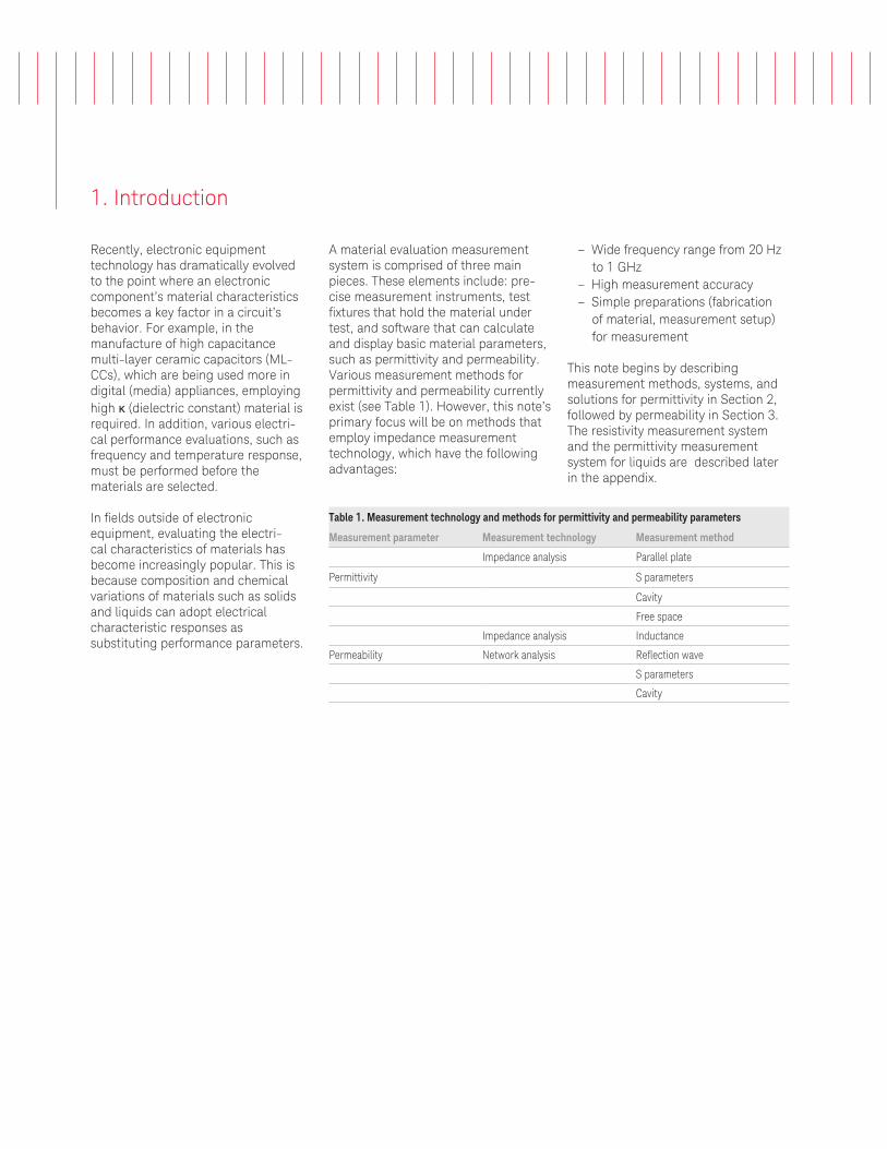
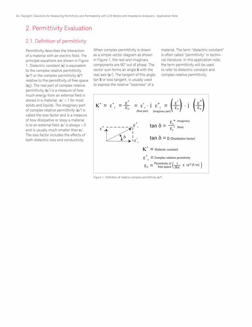
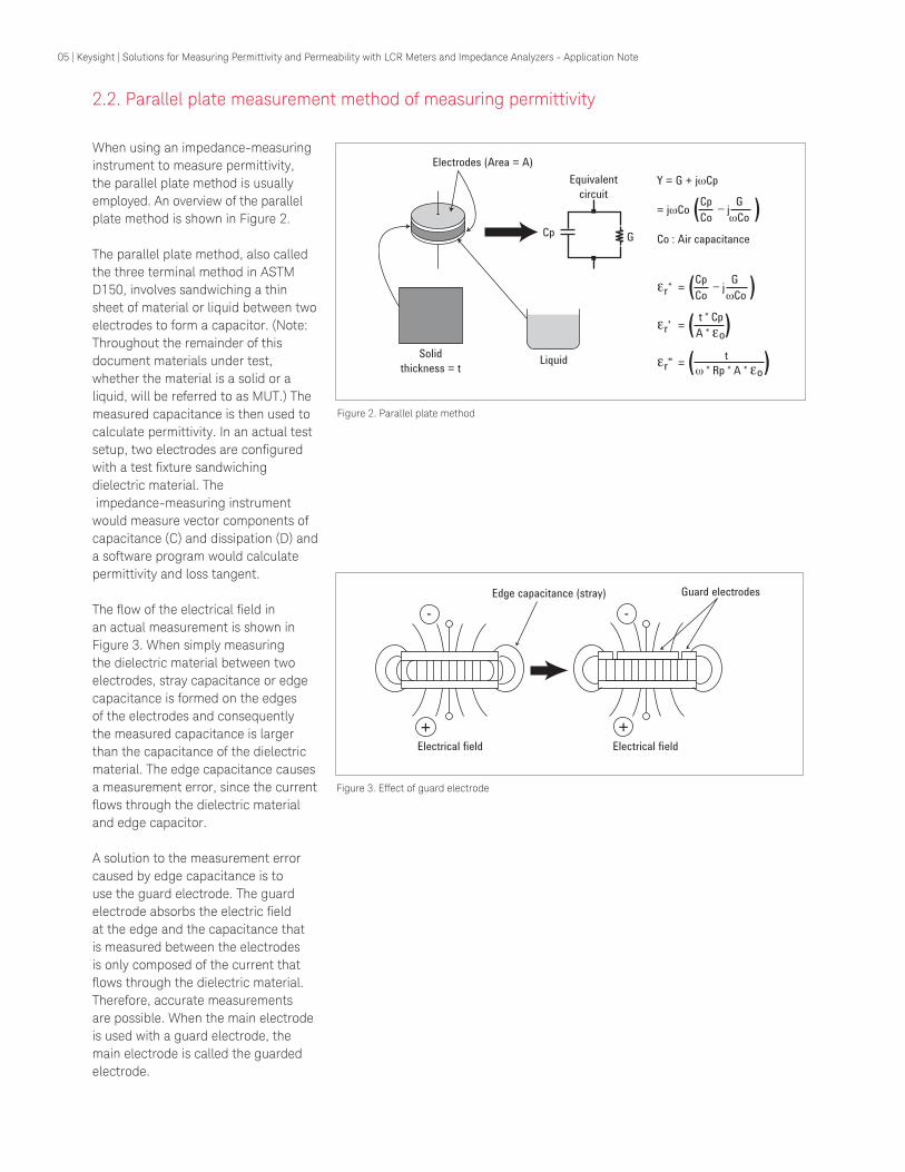
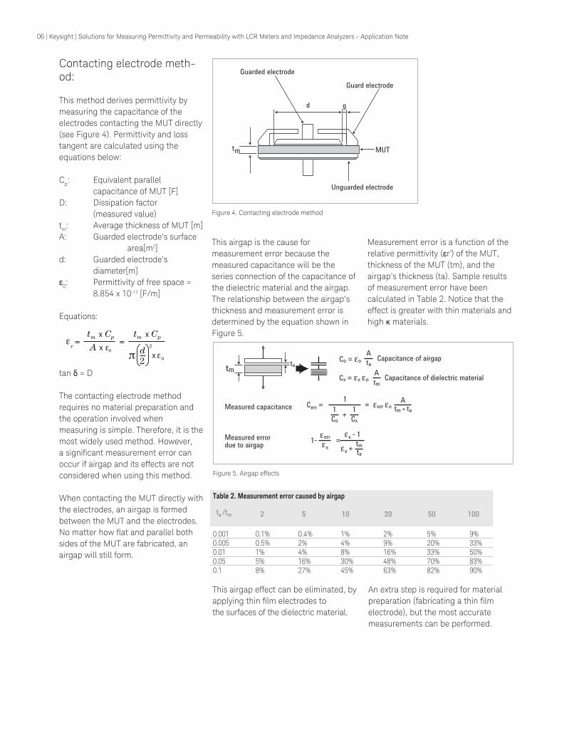
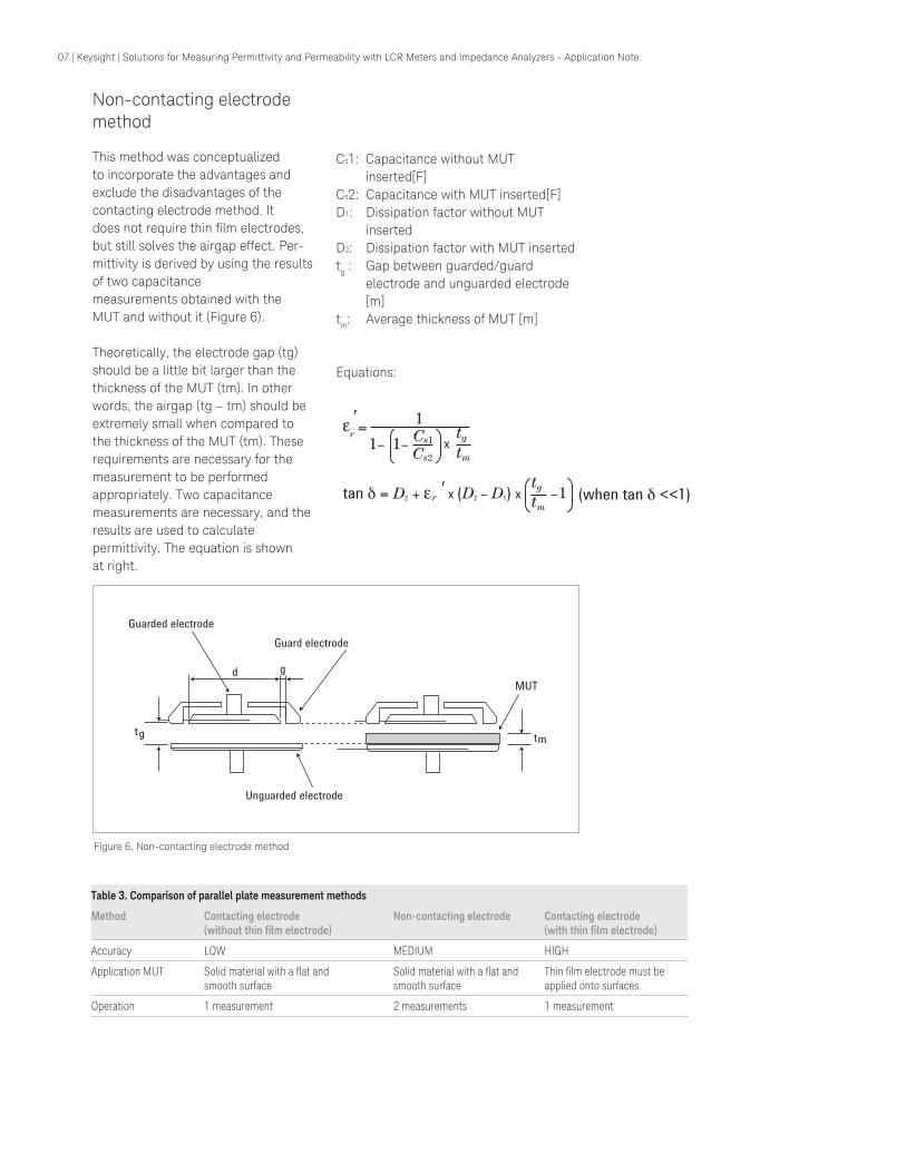
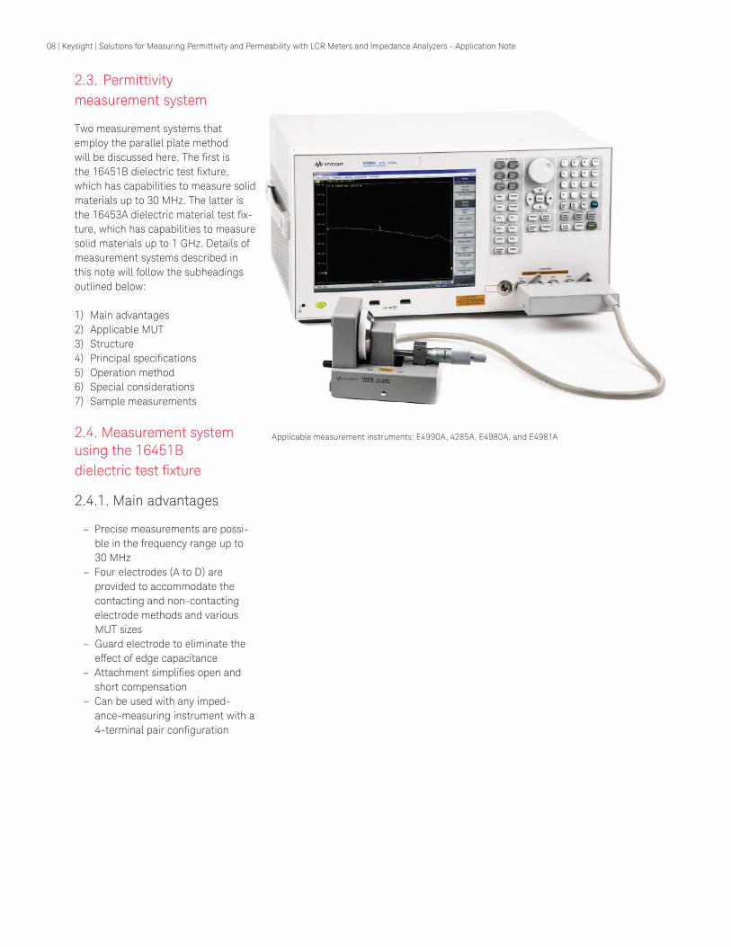
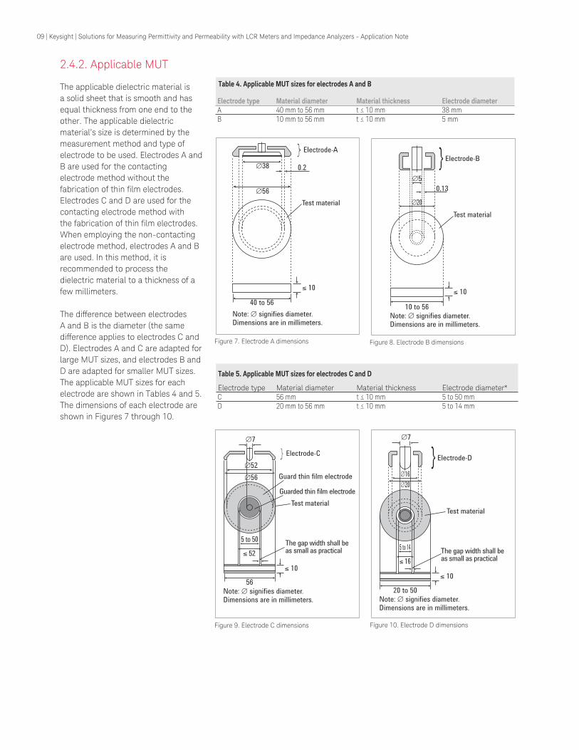
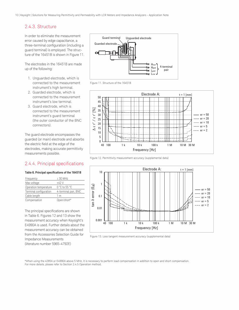
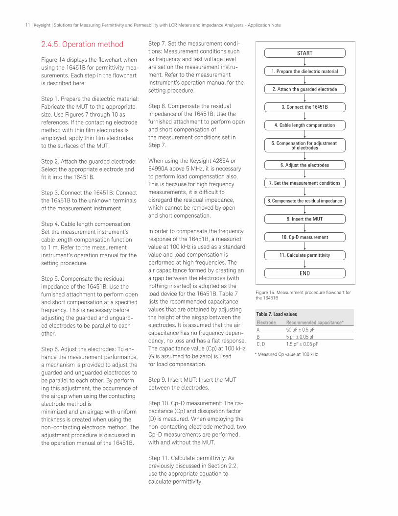
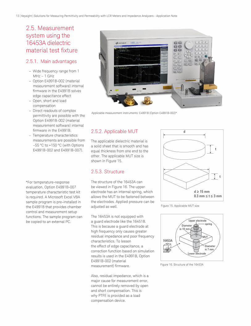
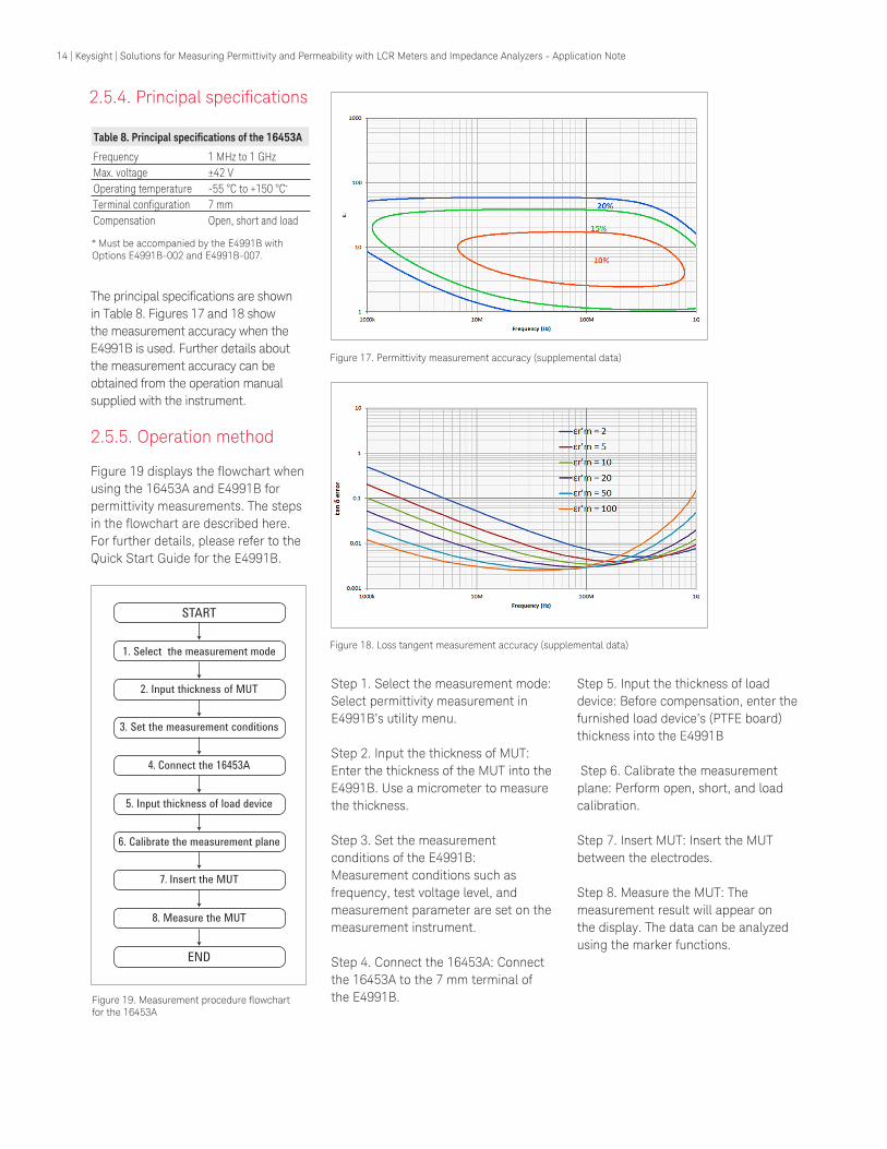
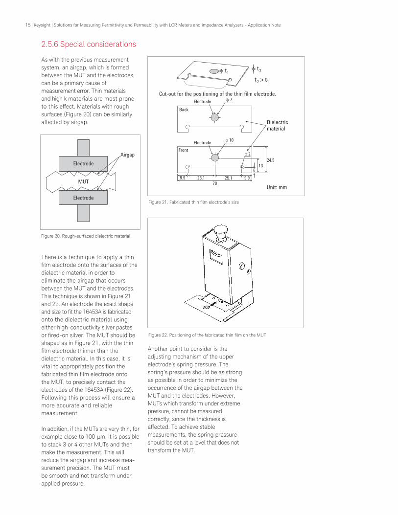
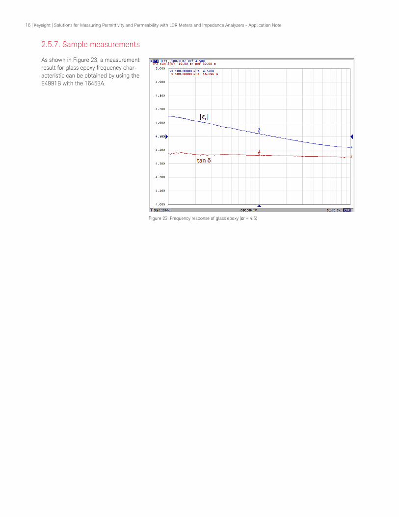
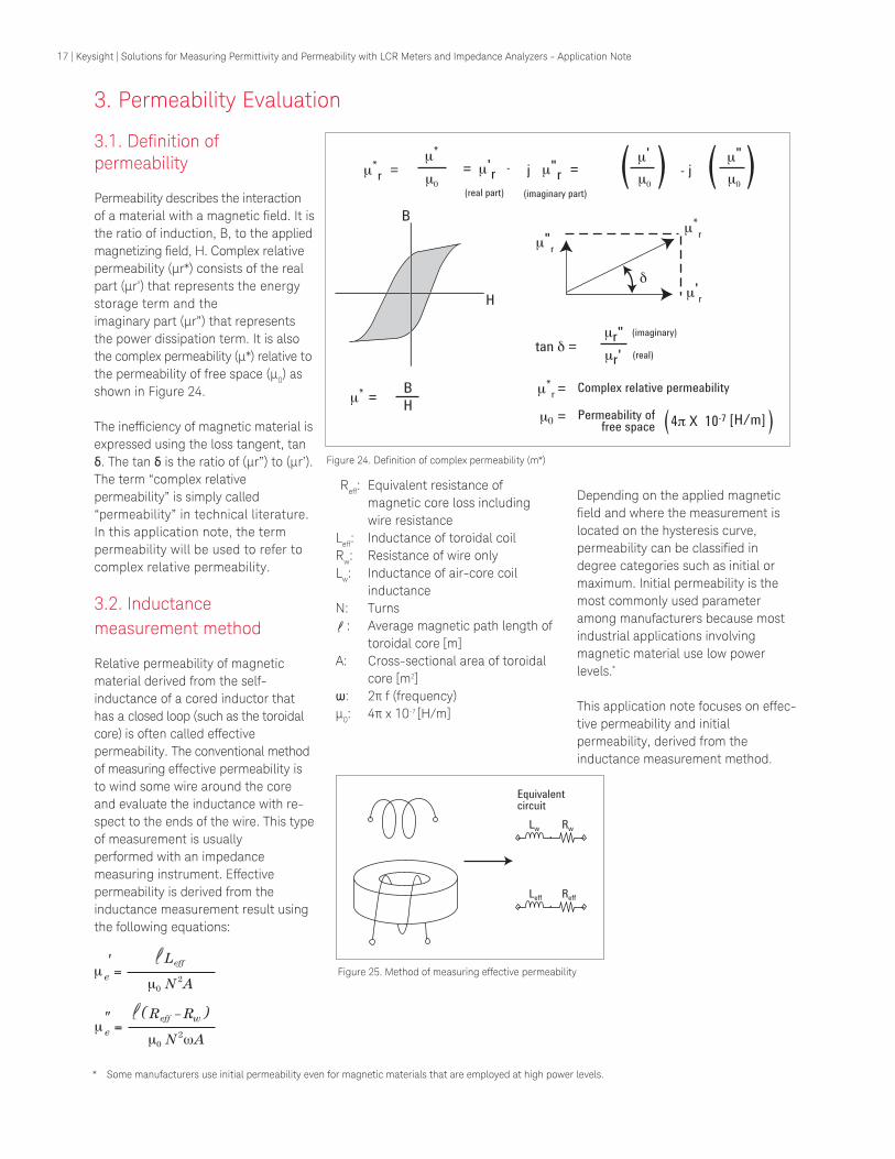
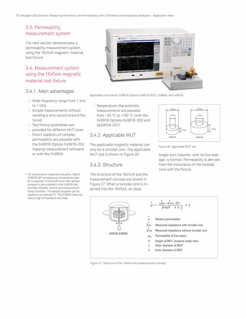
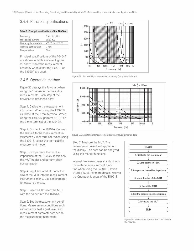
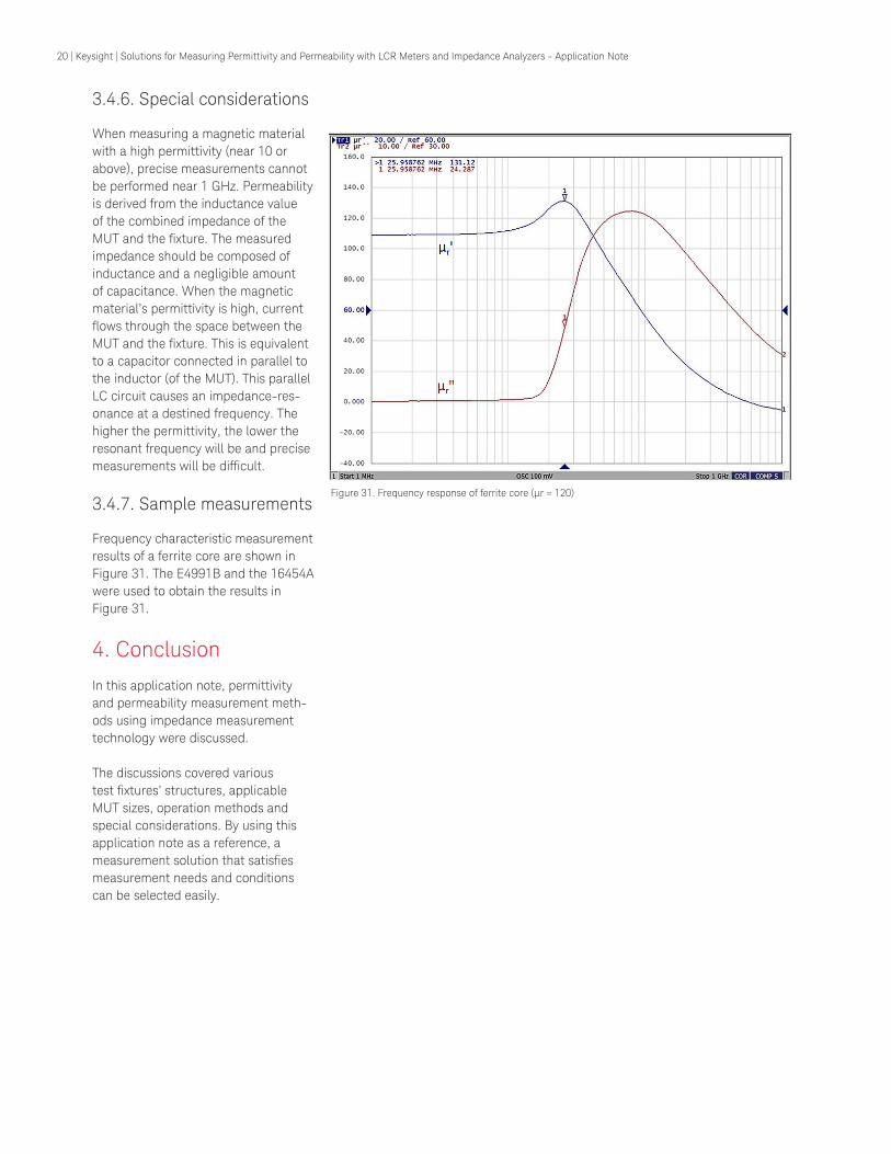
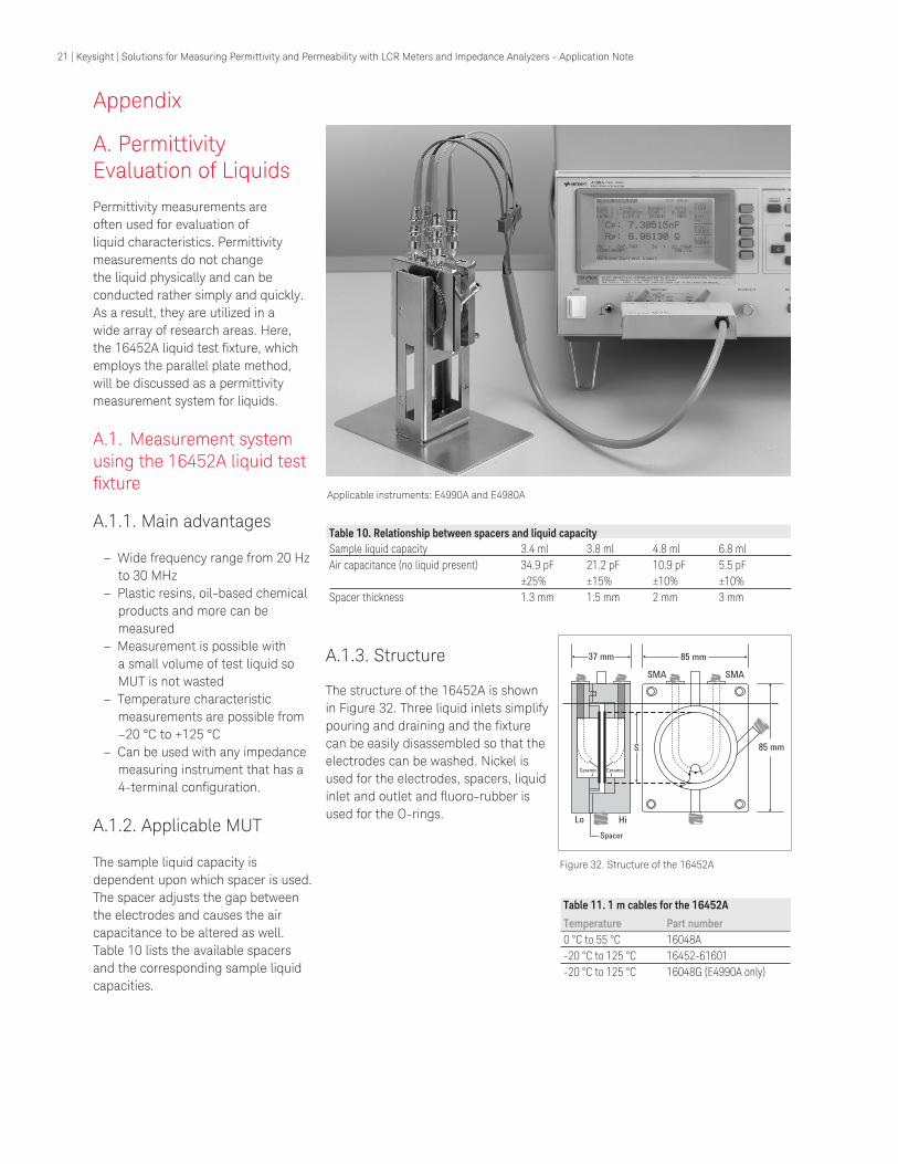
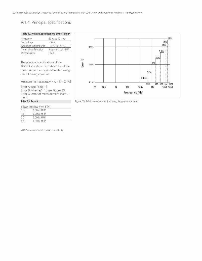
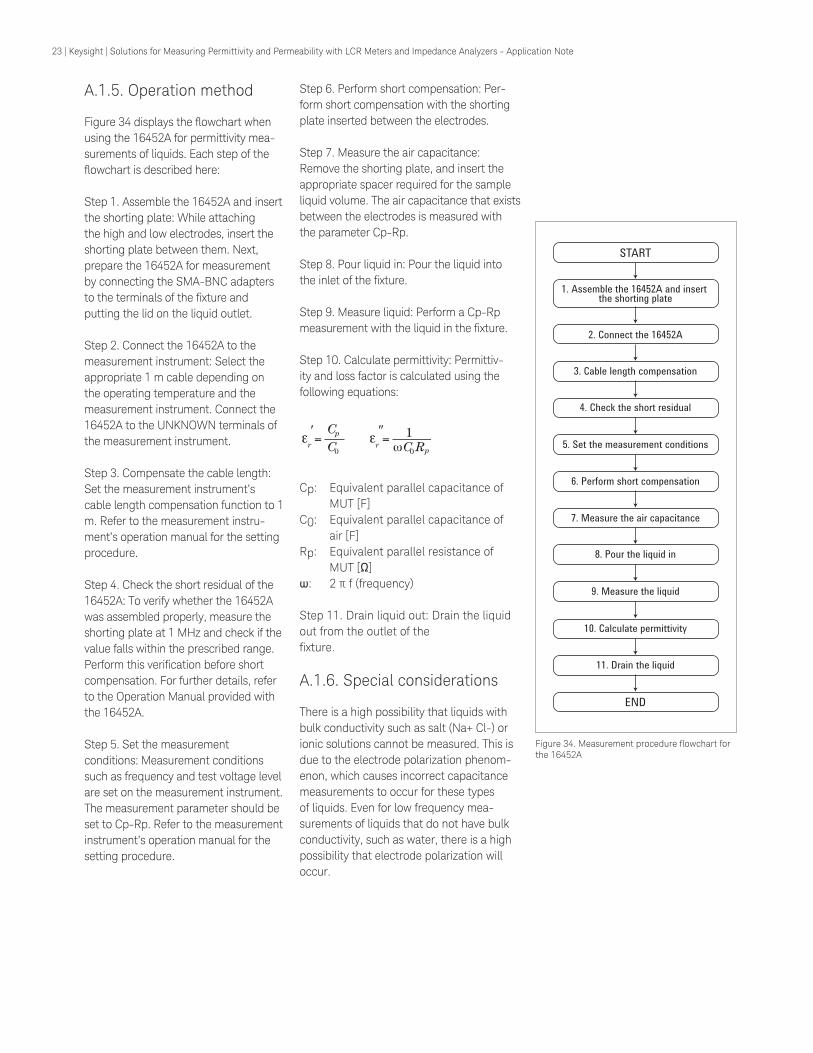