Embed Size (px)
Citation preview
Keysight TechnologiesCustom OFDM Signal Generation Using SystemVue
Application Note
Introduction
Orthogonal frequency-division multiplexing (OFDM) has developed into a
popular scheme for wideband digital communication, both wireless and over
cables (copper wires). This application note provides an introduction to OFDM
technology and explains how to use the Keysight Technologies, Inc. SystemVue
software to generate custom OFDM/OFDMA signals. It also details the method
for linking OFDM signals from 89600B SystemVue to the Keysight Vector Signal
Analysis (VSA) software for demodulation. Commercial availability of both
products is scheduled for Q1 2011.
A demonstration video for this application note can be found at
http://www.keysight.com/ind/eesof-systemvue-videos
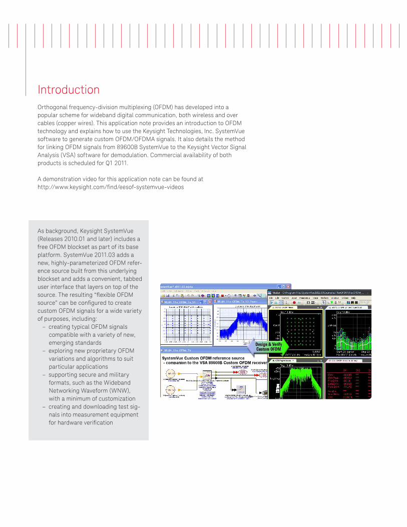
As background, Keysight SystemVue
(Releases 2010.01 and later) includes a
free OFDM blockset as part of its base
platform. SystemVue 2011.03 adds a
new, highly-parameterized OFDM refer-
ence source built from this underlying
blockset and adds a convenient, tabbed
user interface that layers on top of the
source. The resulting “lexible OFDM source” can be conigured to create custom OFDM signals for a wide variety
of purposes, including:
– creating typical OFDM signals
compatible with a variety of new,
emerging standards
– exploring new proprietary OFDM
variations and algorithms to suit
particular applications
– supporting secure and military
formats, such as the Wideband
Networking Waveform (WNW),
with a minimum of customization
– creating and downloading test sig-
nals into measurement equipment
for hardware veriication
3
OFDM is a frequency-division multiplexing (FDM) scheme used as a digital multi-carrier modulation method and is essen-
tially identical to coded OFDM (COFDM) and discrete multi-tone modulation (DMT). It is used in such diverse applications
as digital television and audio broadcasting, wireless networking and broadband internet access. OFDM has also been
adopted in some military communication systems. For example, the WNW format is the next generation high-throughput
military waveform developed under the Joint Tactical Radio System (JTRS) Ground Mobile Radio (GMR) program.
Orthogonal Frequency-Division Multiplexing (OFDM)
Cable
– ADSL and VDSL broadband
access, via POTS copper wiring.
– Power line communication
(G3-PLC, PRIME) used in “smart
grid” applications.
– Multimedia over Coax Alliance
(MoCA) home networking.
– ITU-T G.hn, a standard that
provides high-speed local area
networking over existing home
wiring (power lines, phone lines
and coaxial cables).
– DVB-C2, an enhanced version
of the DVB-C digital cable
TV standard.
Wireless
– Wireless LAN (WLAN) radio
interfaces IEEE 802.11a, g, n
and ac.
– Digital radio systems DAB/
EUREKA 147, DAB+, Digital Radio
Mondiale, HD Radio, T-DMB and
ISDB-TSB.
– Terrestrial digital TV systems
DVB-T and ISDB-T, DVB-T2, an
enhanced version of DVB-T.
– Terrestrial mobile TV systems DVB-
H, T-DMB, ISDB-T and MediaFLO
forward link.
– Wireless MAN/fixed broadband
wireless access (BWA) standard
IEEE 802.16 (WiMAX™).
– The mobile broadband wireless
access IEEE 802.16e (Mobile
WiMAX™) and WiBro.
– 3GPP Long Term Evolution
(LTE) fourth-generation mobile
broadband standard downlink.
– The wireless personal area
network (PAN) ultra-wideband
(UWB) IEEE 802.15.3a (802.11ad
implementation suggested by
WiMedia Alliance),
WiGIG/IEEE 802.
Flexible OFDM Structure
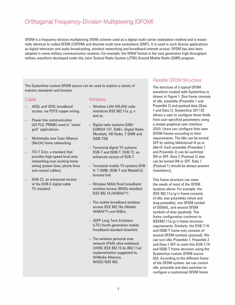
The structure of a typical OFDM
waveform created with SystemVue is
shown in Figure 1. One frame consists
of idle, preamble (Preamble 1 and
Preamble 2) and payload data (Data
1 and Data 2). SystemVue 2011.03
allows a user to configure these fields
from user-specified parameters using
a simple graphical user interface
(GUI). Users can configure their own
OFDM frames according to their
requirements. The Idle can be turned
OFF by setting IdleInterval=0 µs or
Idle=0. Each preamble (Preamble 1
and Preamble 2) can be switched
ON or OFF. Data 2 (Payload 2) also
can be turned ON or OFF. Data 1
(Payload 1) should be always present
(mandatory).
This frame structure can meet
the needs of most of the OFDM
systems above. For example, the
IEEE 802.11a/g/n frame consists
of idle, two preambles (short and
long preamble), one OFDM symbol
of SIGNAL, and several OFDM
symbols of data (payload). The
frame configuration conforms to
IEEE802.11a/g/n frame structure
requirements. Similarly, the DVB-T/H
and ISDB-T frame only consists of
several OFDM symbols (payload). We
can turn idle, Preamble 1, Preamble 2
and Data 2 OFF to meet this DVB-T/H
and ISDB-T frame structure using the
SystemVue custom OFDM source
GUI. According to the different frame
of the OFDM system, we can control
idle, preamble and data switches to
configure a customized OFDM frame.
The SystemVue custom OFDM source can be used to explore a variety of
industry standards and formats.
4
Idle Preamble 1 Preamble 2 Data 1 Data 2
Block Block Block
Block Block Block
OFDMsymbol
Idle can be turned ON/OFF
Preamble 1 can be turned ON/OFF
Preamble 2 can be turned ON/OFF
Data 1 is mandatory
Data 2 can be turned ON/OFF
OFDMsymbol
OFDMsymbol
OFDMsymbol
OFDMsymbol
OFDMsymbol
Figure 1: The frame structure of a flexible OFDM system
Both the Preamble 1 sequence and Preamble 2 sequence can be defined in the frequency domain or time domain,
according to the system specification in the flexible OFDM application. WLAN series standards (802.11a/g/n/ac)
define their preambles in the frequency domain and need to use the Inverse Fast Fourier Transform (IFFT) to trans-
fer the frequency-domain sequence into time-domain signals. WiGIG and MoCA define their preambles in the time
domain and therefore, do not need IFFT when transferring the frequency-domain sequence into the time domain.
According to different OFDM standards, we can set preambles to the frequency domain or time domain in a very
flexible way.
There are two kinds of pilots (Pilot1 and Pilot2) supported in Data 1 and Data 2 payloads. Both Pilot1 and Pilot2 can
be turned ON or OFF, separately. Each OFDM system has its own pilot structure.
In the following section, we introduce preamble structure, payload OFDM symbol structure and pilot structure,
respectively.
5
Preamble Structure
In most OFDM systems (including 802.xx series standards 11a/n/g/11ac, PLC standards G3-PLC, etc…), data transmission
is in burst (non-continuous) mode. Because of the burst nature of data transmission and the fast acquisition times needed,
these systems use preamble-based methods to acquire symbol timing and carrier frequency synchronization at the wire-
less receiver.
Moreover, the preambles are also used for things like automatic gain control (AGC) adaptation, channel estimation and
initial phase reference estimation. Audio (DAB, ISDB-TSB and etc) and video OFDM systems (DVB-T/H/T2/C2, ISDB-T and
etc) do not have any preamble because their data transmission is continuous. For these continuous OFDM systems, the
pilots (continuous and scattered pilots) are used for timing and frequency synchronization and channel estimation instead
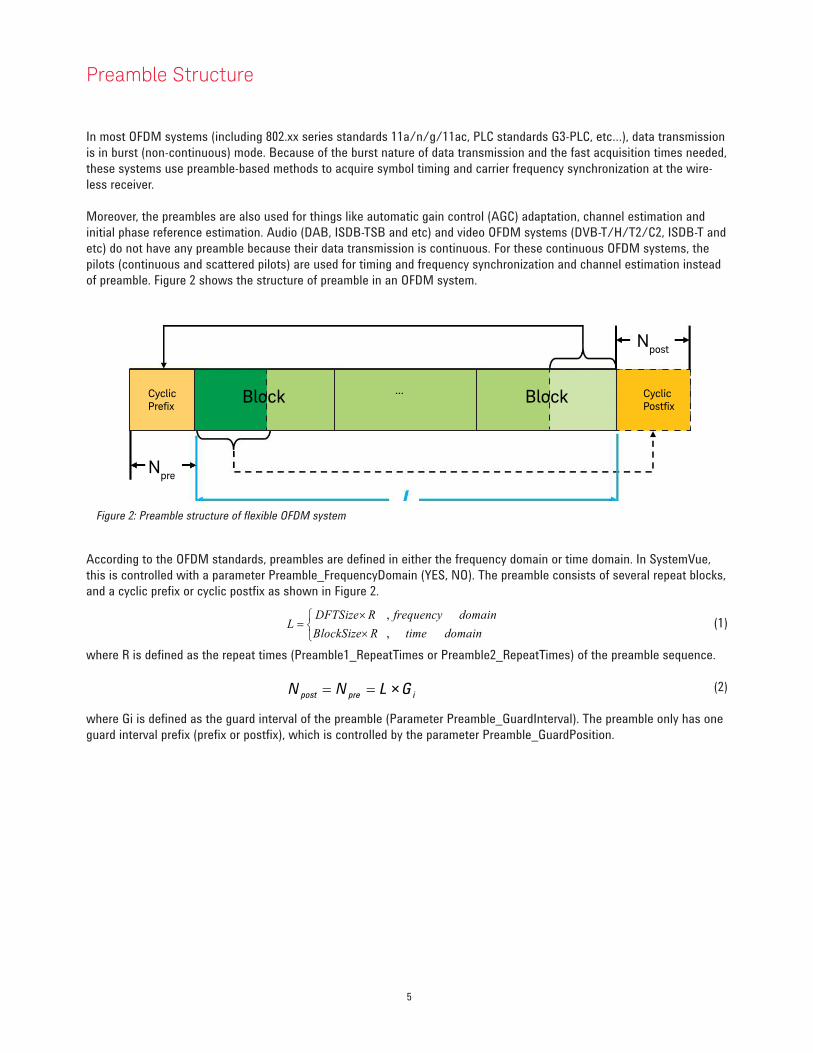
of preamble. Figure 2 shows the structure of preamble in an OFDM system.
Cyclic Prefix
Block ... Block Cyclic Postfix
Npre
Npost
Figure 2: Preamble structure of flexible OFDM system
According to the OFDM standards, preambles are defined in either the frequency domain or time domain. In SystemVue,
this is controlled with a parameter Preamble_FrequencyDomain (YES, NO). The preamble consists of several repeat blocks,
and a cyclic prefix or cyclic postfix as shown in Figure 2.
(1)
where R is defined as the repeat times (Preamble1_RepeatTimes or Preamble2_RepeatTimes) of the preamble sequence.
(2)
where Gi is defined as the guard interval of the preamble (Parameter Preamble_GuardInterval). The preamble only has one
guard interval prefix (prefix or postfix), which is controlled by the parameter Preamble_GuardPosition.
domaintime
domainfrequency
RBlockSize
RDFTSizeL
,
,
×
×=
iprepost GLNN ×==
6
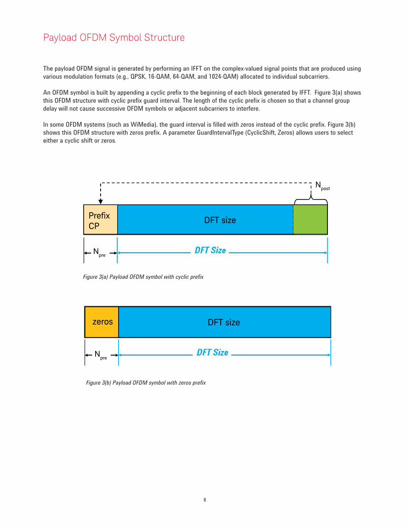
The payload OFDM signal is generated by performing an IFFT on the complex-valued signal points that are produced using
various modulation formats (e.g., QPSK, 16-QAM, 64-QAM, and 1024-QAM) allocated to individual subcarriers.
An OFDM symbol is built by appending a cyclic prefix to the beginning of each block generated by IFFT. Figure 3(a) shows
this OFDM structure with cyclic prefix guard interval. The length of the cyclic prefix is chosen so that a channel group
delay will not cause successive OFDM symbols or adjacent subcarriers to interfere.
In some OFDM systems (such as WiMedia), the guard interval is filled with zeros instead of the cyclic prefix. Figure 3(b)
shows this OFDM structure with zeros prefix. A parameter GuardIntervalType (CyclicShift, Zeros) allows users to select
either a cyclic shift or zeros.
Payload OFDM Symbol Structure
Npre
Npost
PrefixCP
DFT size
zeros DFT size
Npre
Figure 3(a) Payload OFDM symbol with cyclic prefix
Figure 3(b) Payload OFDM symbol with zeros prefix
7
Pilot Structure
There are two kinds of pilots (Pilot1 and Pilot2) supported in Data 1 and Data 2 payloads of the flexible OFDM system.
Each pilot (Pilot 1 or Pilot2) can be turned ON or OFF according to the requirement. The pilots can be used for such things
as phase tracking, channel estimation, and coarse and fine frequency synchronization. Each OFDM system has its own
unique pilot pattern requirements.
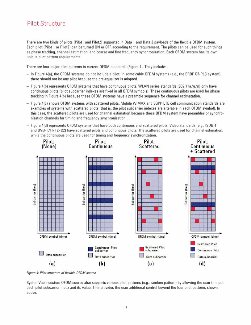
There are four major pilot patterns in current OFDM standards (Figure 4). They include:
– In Figure 4(a), the OFDM systems do not include a pilot. In some cable OFDM systems (e.g., the ERDF G3-PLC system),
there should not be any pilot because the pre-equalizer is adopted.
– Figure 4(b) represents OFDM systems that have continuous pilots. WLAN series standards (802.11a/g/n) only have
continuous pilots (pilot subcarrier indexes are fixed in all OFDM symbols). These continuous pilots are used for phase
tracking in Figure 4(b) because these OFDM systems have a preamble sequence for channel estimatation.
– Figure 4(c) shows OFDM systems with scattered pilots. Mobile WiMAX and 3GPP LTE cell communication standards are
examples of systems with scattered pilots (that is, the pilot subcarrier indexes are alterable in each OFDM symbol). In
this case, the scattered pilots are used for channel estimation because these OFDM system have preambles or synchro-
nization channels for timing and frequency synchronization.
– Figure 4(d) represents OFDM systems that have both continuous and scattered pilots. Video standards (e.g., ISDB-T
and DVB-T/H/T2/C2) have scattered pilots and continuous pilots. The scattered pilots are used for channel estimation,
while the continuous pilots are used for timing and frequency synchronization.
Figure 4: Pilot structure of flexible OFDM source
SystemVue’s custom OFDM source also supports various pilot patterns (e.g., random pattern) by allowing the user to input
each pilot subcarrier index and its value. This provides the user additional control beyond the four pilot patterns shown
above.
8
Mapping Relationship between the OFDM Subcarrier and IFFT Buffer
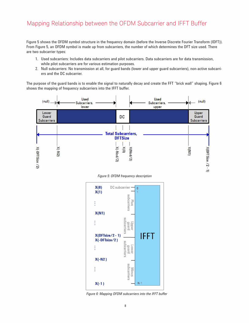
Figure 5 shows the OFDM symbol structure in the frequency domain (before the Inverse Discrete Fourier Transform (IDFT)).
From Figure 5, an OFDM symbol is made up from subcarriers, the number of which determines the DFT size used. There
are two subcarrier types:
1. Used subcarriers: Includes data subcarriers and pilot subcarriers. Data subcarriers are for data transmission,
while pilot subcarriers are for various estimation purposes.
2. Null subcarriers: No transmission at all, for guard bands (lower and upper guard subcarriers), non-active subcarri-
ers and the DC subcarrier.
The purpose of the guard bands is to enable the signal to naturally decay and create the FFT “brick wall” shaping. Figure 6
shows the mapping of frequency subcarriers into the IFFT buffer.
Figure 5: OFDM frequency description
Figure 6: Mapping OFDM subcarriers into the IFFT buffer
9
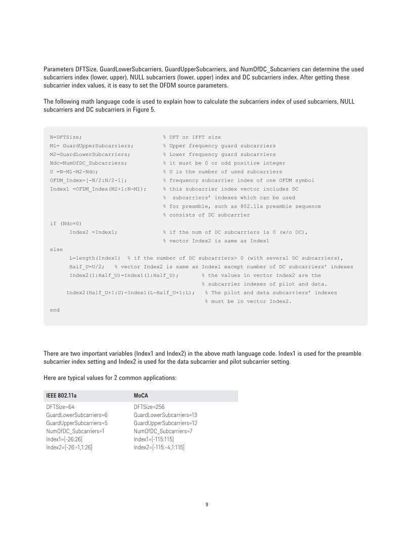
Parameters DFTSize, GuardLowerSubcarriers, GuardUpperSubcarriers, and NumOfDC_Subcarriers can determine the used
subcarriers index (lower, upper), NULL subcarriers (lower, upper) index and DC subcarriers index. After getting these
subcarrier index values, it is easy to set the OFDM source parameters.
The following math language code is used to explain how to calculate the subcarriers index of used subcarriers, NULL
subcarriers and DC subcarriers in Figure 5.
N=DFTSize; % DFT or IFFT size
M1= GuardUpperSubcarriers; % Upper frequency guard subcarriers
M2=GuardLowerSubcarriers; % Lower frequency guard subcarriers
Ndc=NumOfDC_Subcarriers; % it must be 0 or odd positive integer
U =N-M1-M2-Ndc; % U is the number of used subcarriers
OFDM_Index=[-N/2:N/2-1]; % frequency subcarrier index of one OFDM symbol
Index1 =OFDM_Index(M2+1:N-M1); % this subcarrier index vector includes DC
% subcarriers’ indexes which can be used
% for preamble, such as 802.11a preamble sequence
% consists of DC subcarrier
if (Ndc=0)
Index2 =Index1; % if the num of DC subcarriers is 0 (w/o DC),
% vector Index2 is same as Index1
else
L=length(Index1) % if the number of DC subcarriers> 0 (with several DC subcarriers),
Half_U=U/2; % vector Index2 is same as Index1 except number of DC subcarriers’ indexes
Index2(1:Half_U)=Index1(1:Half_U); % the values in vector Index2 are the
% subcarrier indexes of pilot and data.
Index2(Half_U+1:U)=Index1(L-Half_U+1:L); % The pilot and data subcarriers’ indexes
% must be in vector Index2.
end
There are two important variables (Index1 and Index2) in the above math language code. Index1 is used for the preamble
subcarrier index setting and Index2 is used for the data subcarrier and pilot subcarrier setting.
Here are typical values for 2 common applications:
IEEE 802.11a MoCA
DFTSize=64
GuardLowerSubcarriers=6
GuardUpperSubcarriers=5
NumOfDC_Subcarriers=1
Index1=[-26:26]
Index2=[-26:-1,1:26]
DFTSize=256
GuardLowerSubcarriers=13
GuardUpperSubcarriers=12
NumOfDC_Subcarriers=7
Index1=[-115:115]
Index2=[-115:-4,1:115]
10
The SystemVue Flexible OFDM User Interface
Parameter Relationships
In the user interface of the SystemVue custom OFDM source, several key top-level parameters enable or disable
sets of underlying values and settings. For example, the parameter OFDMSubcarrierAllocationType (values = “Fixed”
or “Alterable”) determines parameters Data_NumOfCarriers, Pilot1_NumOfCarriers if Pilot1_Enable=ON, Pilot2_
NumOfCarriers (if Pilot2_Enable=ON), and EVMRef_NumOfCarriers are a single value or row vector, respectively.
OFDM Subcarrier Allocation Type
If the data subcarrier and pilot subcarrier index are fixed (e.g., MoCA and 802.11a/n), then the parameter
OFDMSubcarrierAllocationType must be set to “Fixed.”
If data subcarrier and pilot subcarrier indexes can change in each OFDM symbol (such as LTE, DVB-T2/C2 and etc), then
the parameter OFDMSubcarrierAllocationType should be set to a value of “Alterable.”
These choices then turn on and off additional parameters and determine array sizes, which are documented in the manual
for the custom OFDM source.
Flexible OFDM GUI | System
When we place the FlexOFDM_Source_RF model into the schematic and double click on it, we see the GUI of
FlexOFDM_Source_RF. In the next several sections, we introduce each page of FlexOFDM_Source_RF GUI.
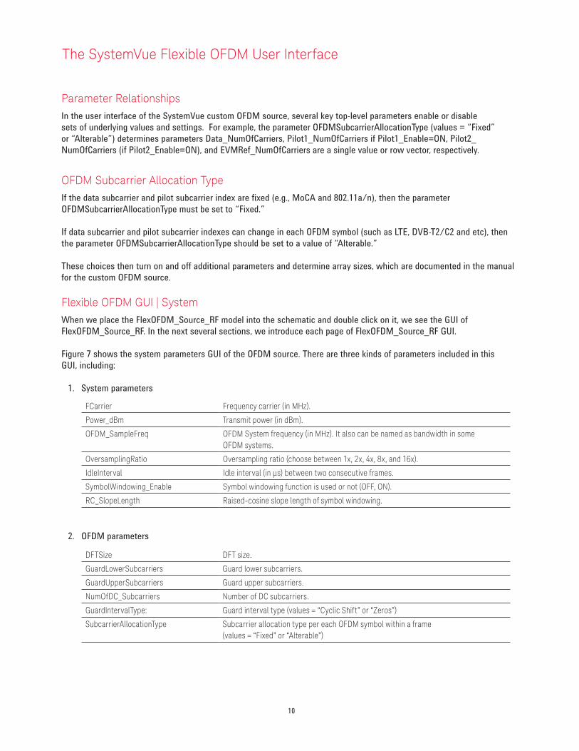
Figure 7 shows the system parameters GUI of the OFDM source. There are three kinds of parameters included in this
GUI, including:
1. System parameters
2. OFDM parameters
FCarrier Frequency carrier (in MHz).
Power_dBm Transmit power (in dBm).
OFDM_SampleFreq OFDM System frequency (in MHz). It also can be named as bandwidth in some
OFDM systems.
OversamplingRatio Oversampling ratio (choose between 1x, 2x, 4x, 8x, and 16x).
IdleInterval Idle interval (in µs) between two consecutive frames.
SymbolWindowing_Enable Symbol windowing function is used or not (OFF, ON).
RC_SlopeLength Raised-cosine slope length of symbol windowing.
DFTSize DFT size.
GuardLowerSubcarriers Guard lower subcarriers.
GuardUpperSubcarriers Guard upper subcarriers.
NumOfDC_Subcarriers Number of DC subcarriers.
GuardIntervalType: Guard interval type (values = “Cyclic Shift” or “Zeros”)
SubcarrierAllocationType Subcarrier allocation type per each OFDM symbol within a frame
(values = “Fixed” or “Alterable”)
11
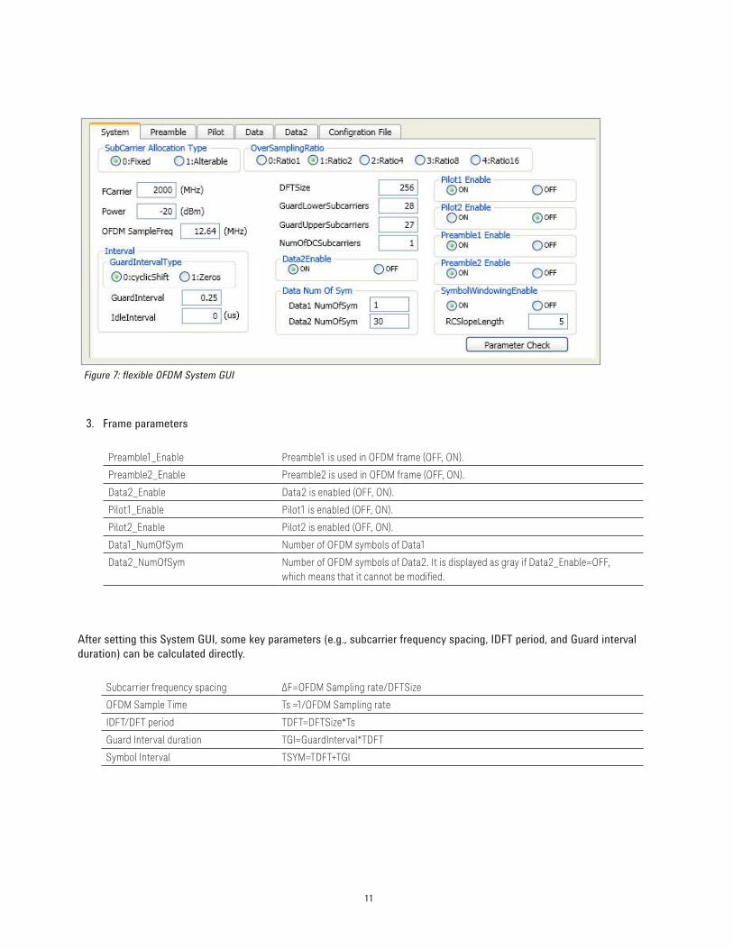
3. Frame parameters
After setting this System GUI, some key parameters (e.g., subcarrier frequency spacing, IDFT period, and Guard interval
duration) can be calculated directly.
Preamble1_Enable Preamble1 is used in OFDM frame (OFF, ON).
Preamble2_Enable Preamble2 is used in OFDM frame (OFF, ON).
Data2_Enable Data2 is enabled (OFF, ON).
Pilot1_Enable Pilot1 is enabled (OFF, ON).
Pilot2_Enable Pilot2 is enabled (OFF, ON).
Data1_NumOfSym Number of OFDM symbols of Data1
Data2_NumOfSym Number of OFDM symbols of Data2. It is displayed as gray if Data2_Enable=OFF,
which means that it cannot be modiied.
Figure 7: flexible OFDM System GUI
Subcarrier frequency spacing ΔF=OFDM Sampling rate/DFTSize
OFDM Sample Time Ts =1/OFDM Sampling rate
IDFT/DFT period TDFT=DFTSize*Ts
Guard Interval duration TGI=GuardInterval*TDFT
Symbol Interval TSYM=TDFT+TGI
12
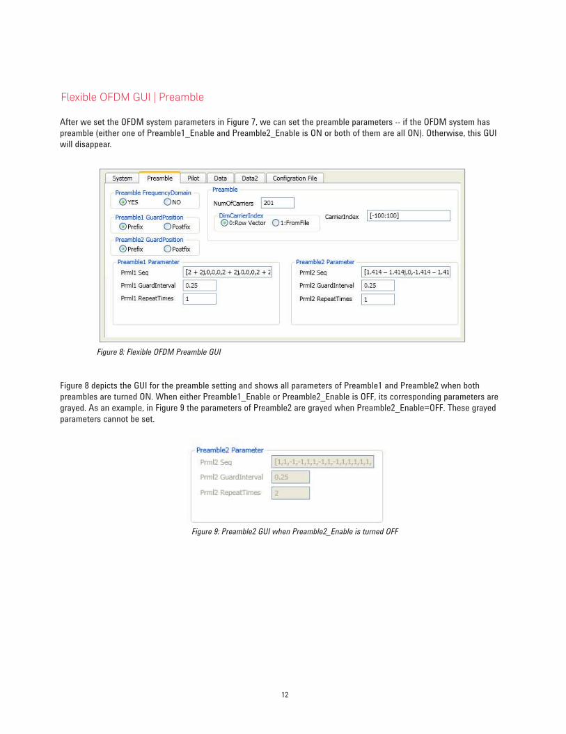
Flexible OFDM GUI | Preamble
After we set the OFDM system parameters in Figure 7, we can set the preamble parameters -- if the OFDM system has
preamble (either one of Preamble1_Enable and Preamble2_Enable is ON or both of them are all ON). Otherwise, this GUI
will disappear.
Figure 8: Flexible OFDM Preamble GUI
Figure 8 depicts the GUI for the preamble setting and shows all parameters of Preamble1 and Preamble2 when both
preambles are turned ON. When either Preamble1_Enable or Preamble2_Enable is OFF, its corresponding parameters are
grayed. As an example, in Figure 9 the parameters of Preamble2 are grayed when Preamble2_Enable=OFF. These grayed
parameters cannot be set.
Figure 9: Preamble2 GUI when Preamble2_Enable is turned OFF
13
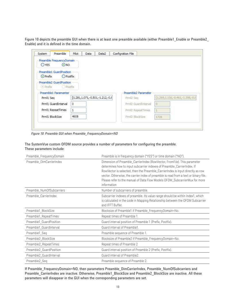
Figure 10 depicts the preamble GUI when there is at least one preamble available (either Preamble1_Enable or Preamble2_
Enable) and it is defined in the time domain.
Figure 10: Preamble GUI when Preamble_FrequencyDomain=NO
The SystemVue custom OFDM source provides a number of parameters for configuring the preamble.
These parameters include:
Preamble_FrequencyDomain Preamble is in frequency domain (“YES”) or time domain (“NO”).
Preamble_DimCarrierIndex Dimension of Preamble_CarrierIndex (RowVector, FromFile). This parameter
determines how to input subcarrier indexes of Preamble_CarrierIndex. If
RowVector is selected, then the Preamble_CarrierIndex is input directly as row
vector. Otherwise, the carrier index of preamble is read from a text or binary ile. Please refer to the manual of Data Flow Models OFDM_SubcarrierMux for more
information
Preamble_NumOfSubcarriers Number of subcarriers of preamble.
Preamble_CarrierIndex Subcarrier indexes of preamble. Its value range should be within Index1, which
is calculated in the code in Mapping Relationship between the OFDM Subcarrier
and IFFT Buffer.
Preamble1_BlockSize Blocksize of Preamble1 if Preamble_FrequencyDomain=No.
Preamble1_RepeatTimes Repeat times of Preamble 1.
Preamble1_GuardPosition Guard interval position of Preamble 1 (Preix, Postix).
Preamble1_GuardInterval Guard interval of Preamble1.
Preamble1_Seq Preamble sequence of Preamble 1.
Preamble2_BlockSize Blocksize of Preamble2 if Preamble_FrequencyDomain=No.
Preamble2_RepeatTimes Repeat times of Preamble 2
Preamble2_GuardPosition Guard interval position of Preamble 2 (Preix, Postix).
Preamble2_GuardInterval Guard interval of Preamble2.
Preamble2_Seq Preamble sequence of Preamble 2.
If Preamble_FrequencyDomain=NO, then parameters Preamble_DimCarrierIndex, Preamble_NumOfSubcarriers and
Preamble_CarrierIndex are inactive. Otherwise, Preamble1_BlockSize and Preamble2_BlockSize are inactive. All these
parameters will disappear in the GUI when the corresponding parameters are set.
14
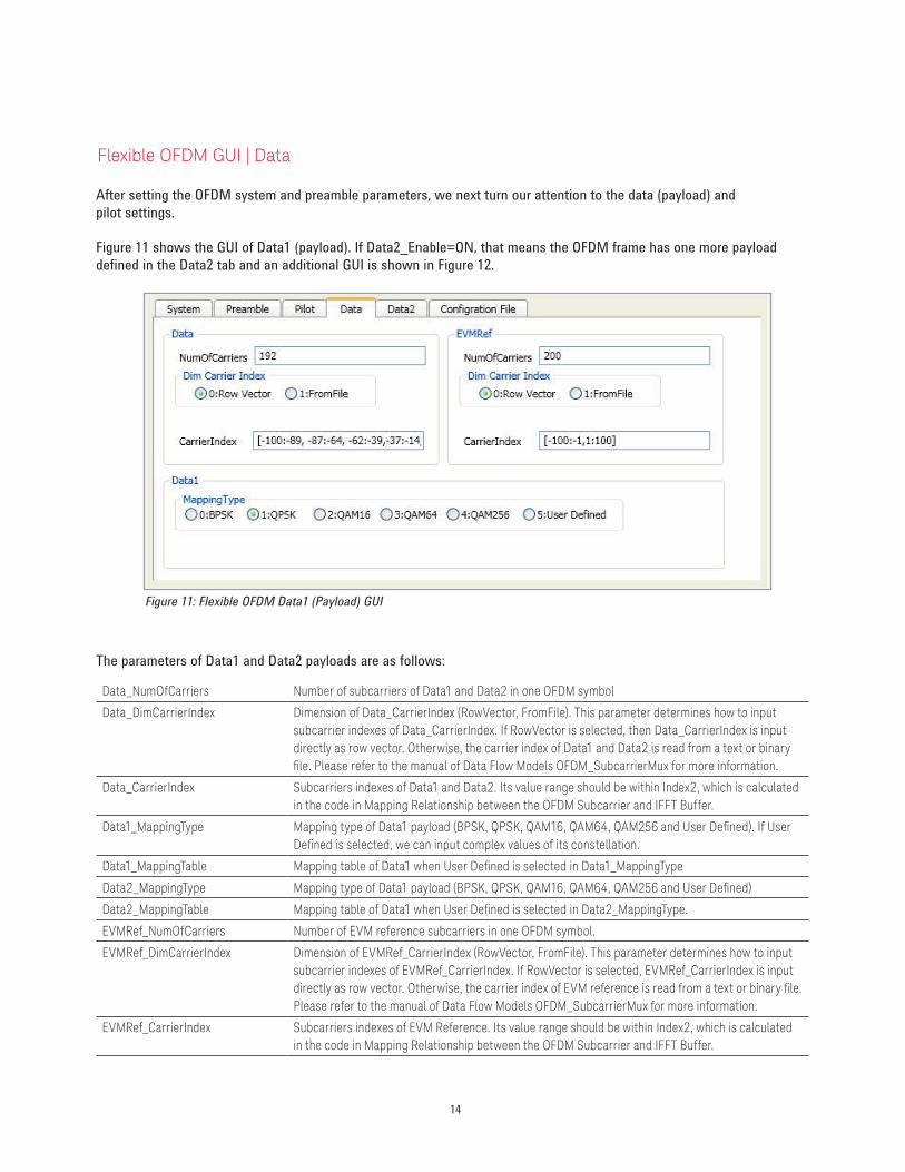
Flexible OFDM GUI | Data
After setting the OFDM system and preamble parameters, we next turn our attention to the data (payload) and
pilot settings.
Figure 11 shows the GUI of Data1 (payload). If Data2_Enable=ON, that means the OFDM frame has one more payload
defined in the Data2 tab and an additional GUI is shown in Figure 12.
Figure 11: Flexible OFDM Data1 (Payload) GUI
The parameters of Data1 and Data2 payloads are as follows:
Data_NumOfCarriers Number of subcarriers of Data1 and Data2 in one OFDM symbol
Data_DimCarrierIndex Dimension of Data_CarrierIndex (RowVector, FromFile). This parameter determines how to input
subcarrier indexes of Data_CarrierIndex. If RowVector is selected, then Data_CarrierIndex is input
directly as row vector. Otherwise, the carrier index of Data1 and Data2 is read from a text or binary
ile. Please refer to the manual of Data Flow Models OFDM_SubcarrierMux for more information.
Data_CarrierIndex Subcarriers indexes of Data1 and Data2. Its value range should be within Index2, which is calculated
in the code in Mapping Relationship between the OFDM Subcarrier and IFFT Buffer.
Data1_MappingType Mapping type of Data1 payload (BPSK, QPSK, QAM16, QAM64, QAM256 and User Deined). If User Deined is selected, we can input complex values of its constellation.
Data1_MappingTable Mapping table of Data1 when User Deined is selected in Data1_MappingType
Data2_MappingType Mapping type of Data1 payload (BPSK, QPSK, QAM16, QAM64, QAM256 and User Deined)
Data2_MappingTable Mapping table of Data1 when User Deined is selected in Data2_MappingType.
EVMRef_NumOfCarriers Number of EVM reference subcarriers in one OFDM symbol.
EVMRef_DimCarrierIndex Dimension of EVMRef_CarrierIndex (RowVector, FromFile). This parameter determines how to input
subcarrier indexes of EVMRef_CarrierIndex. If RowVector is selected, EVMRef_CarrierIndex is input
directly as row vector. Otherwise, the carrier index of EVM reference is read from a text or binary ile. Please refer to the manual of Data Flow Models OFDM_SubcarrierMux for more information.
EVMRef_CarrierIndex Subcarriers indexes of EVM Reference. Its value range should be within Index2, which is calculated
in the code in Mapping Relationship between the OFDM Subcarrier and IFFT Buffer.
15
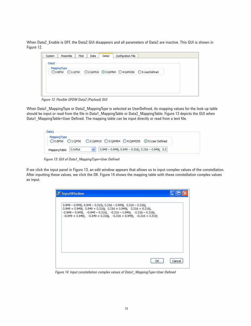
When Data2_Enable is OFF, the Data2 GUI disappears and all parameters of Data2 are inactive. This GUI is shown in
Figure 12.
Figure 12: Flexible OFDM Data2 (Payload) GUI
When Data1_MappingType or Data2_MappingType is selected as UserDefined, its mapping values for the look-up table
should be input or read from the file in Data1_MappingTable or Data2_MappingTable. Figure 13 depicts the GUI when
Data1_MappingTable=User Defined. The mapping table can be input directly or read from a text file.
Figure 13: GUI of Data1_MappingType=User Defined
If we click the input panel in Figure 13, an edit window appears that allows us to input complex values of the constellation.
After inputting these values, we click the OK. Figure 14 shows the mapping table with these constellation complex values
as input.
Figure 14: Input constellation complex values of Data1_MappingType=User Defined
16
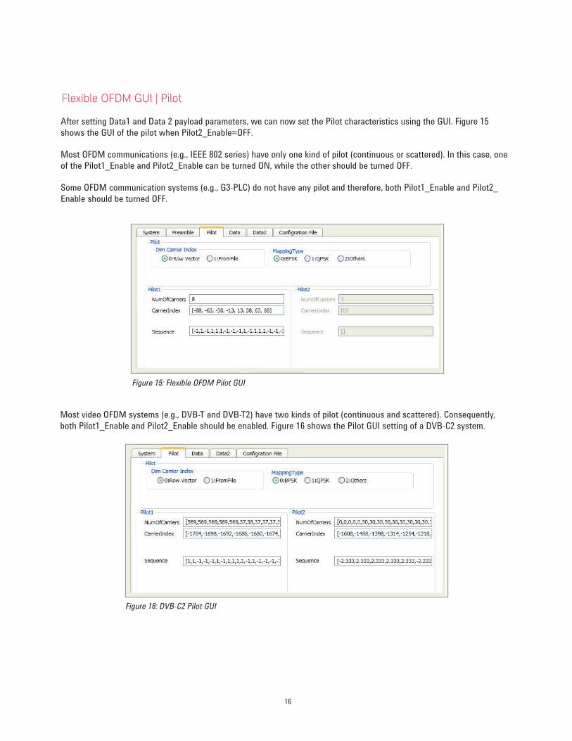
Flexible OFDM GUI | Pilot
After setting Data1 and Data 2 payload parameters, we can now set the Pilot characteristics using the GUI. Figure 15
shows the GUI of the pilot when Pilot2_Enable=OFF.
Most OFDM communications (e.g., IEEE 802 series) have only one kind of pilot (continuous or scattered). In this case, one
of the Pilot1_Enable and Pilot2_Enable can be turned ON, while the other should be turned OFF.
Some OFDM communication systems (e.g., G3-PLC) do not have any pilot and therefore, both Pilot1_Enable and Pilot2_
Enable should be turned OFF.
Figure 15: Flexible OFDM Pilot GUI
Most video OFDM systems (e.g., DVB-T and DVB-T2) have two kinds of pilot (continuous and scattered). Consequently,
both Pilot1_Enable and Pilot2_Enable should be enabled. Figure 16 shows the Pilot GUI setting of a DVB-C2 system.
Figure 16: DVB-C2 Pilot GUI
17
There are a number of parameters available to configure the pilot. These parameters include:
Pilot_MappingType Mapping type of Pilot (BPSK, QPSK, and others). This parameter is only used to generate external
coniguration iles for Keysight’s VSA 89600B software. The Keysight VSA S89600B needs to know the modulation type of the pilot when it demodulates the OFDM waveforms generated by the Sys-
temVue OFDM source.
Pilot_DimCarrierIndex Dimension of Pilot1_CarrierIndex and Pilot2_CarrierIndex (RowVector, FromFile). This parameter
determines how to input subcarrier indexes of Pilot1_CarrierIndex and Pilot2_CarrierIndex. If
RowVector is selected, Pilot1_CarrierIndex and Pilot2_CarrierIndex are input directly as row vector.
Otherwise, the carrier index of Pilot1 and Pilot2 is read from a text or binary ile. Please refer to the manual of Data Flow Models OFDM_SubcarrierMux for more information.
Pilot1_NumOfCarriers Number of subcarriers of Pilot1 in one OFDM symbol.
Pilot1_CarrierIndex Subcarriers indexes of Pilot1. Its value range should be within Index2, which is calculated in the code
shown in the Mapping Relationship between the OFDM Subcarrier and IFFT Buffer.
Pilot1_Seq Pilot1 sequence in all payload OFDM symbols (Data_NumOfSym in Equation 5).
Pilot2_NumOfCarriers Number of subcarriers of Pilot2 in one OFDM symbol.
Pilot2_CarrierIndex Subcarriers indexes of Pilot2. Its value range is deined in Index2.
Pilot2_Seq Pilot2 sequence in all payload OFDM symbols (Data_NumOfSym in Equation 5).
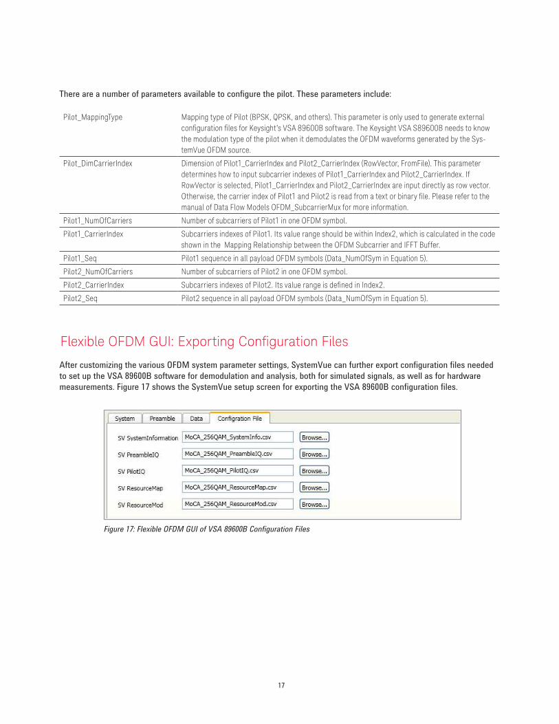
Flexible OFDM GUI: Exporting Coniguration Files
After customizing the various OFDM system parameter settings, SystemVue can further export configuration files needed
to set up the VSA 89600B software for demodulation and analysis, both for simulated signals, as well as for hardware
measurements. Figure 17 shows the SystemVue setup screen for exporting the VSA 89600B configuration files.
Figure 17: Flexible OFDM GUI of VSA 89600B Configuration Files
18
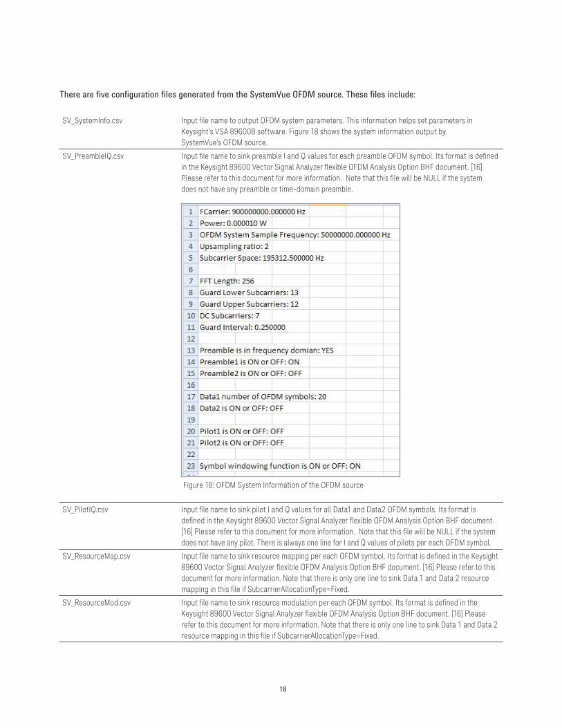
There are five configuration files generated from the SystemVue OFDM source. These files include:
SV_SystemInfo.csv Input ile name to output OFDM system parameters. This information helps set parameters in Keysight’s VSA 89600B software. Figure 18 shows the system information output by SystemVue’s OFDM source.
SV_PreambleIQ.csv Input ile name to sink preamble I and Q values for each preamble OFDM symbol. Its format is deined in the Keysight 89600 Vector Signal Analyzer lexible OFDM Analysis Option BHF document. [16] Please refer to this document for more information. Note that this ile will be NULL if the system does not have any preamble or time-domain preamble.
Figure 18: OFDM System Information of the OFDM source
SV_PilotIQ.csv Input ile name to sink pilot I and Q values for all Data1 and Data2 OFDM symbols. Its format is deined in the Keysight 89600 Vector Signal Analyzer lexible OFDM Analysis Option BHF document. [16] Please refer to this document for more information. Note that this ile will be NULL if the system does not have any pilot. There is always one line for I and Q values of pilots per each OFDM symbol.
SV_ResourceMap.csv Input ile name to sink resource mapping per each OFDM symbol. Its format is deined in the Keysight 89600 Vector Signal Analyzer lexible OFDM Analysis Option BHF document. [16] Please refer to this document for more information. Note that there is only one line to sink Data 1 and Data 2 resource
mapping in this ile if SubcarrierAllocationType=Fixed.
SV_ResourceMod.csv Input ile name to sink resource modulation per each OFDM symbol. Its format is deined in the Keysight 89600 Vector Signal Analyzer lexible OFDM Analysis Option BHF document. [16] Please refer to this document for more information. Note that there is only one line to sink Data 1 and Data 2
resource mapping in this ile if SubcarrierAllocationType=Fixed.
19
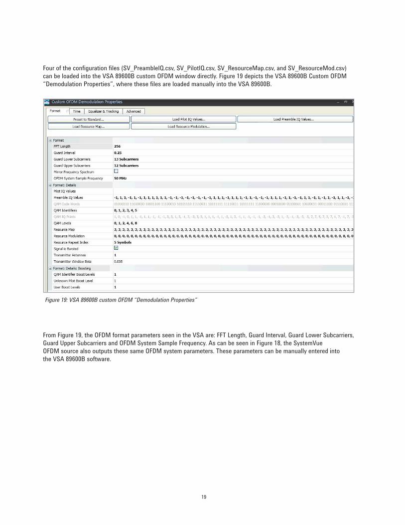
Four of the configuration files (SV_PreambleIQ.csv, SV_PilotIQ.csv, SV_ResourceMap.csv, and SV_ResourceMod.csv)
can be loaded into the VSA 89600B custom OFDM window directly. Figure 19 depicts the VSA 89600B Custom OFDM
“Demodulation Properties”, where these files are loaded manually into the VSA 89600B.
Figure 19: VSA 89600B custom OFDM “Demodulation Properties”
From Figure 19, the OFDM format parameters seen in the VSA are: FFT Length, Guard Interval, Guard Lower Subcarriers,
Guard Upper Subcarriers and OFDM System Sample Frequency. As can be seen in Figure 18, the SystemVue
OFDM source also outputs these same OFDM system parameters. These parameters can be manually entered into
the VSA 89600B software.
20
Examples
SystemVue provides examples with several pre-configured OFDM waveforms. These examples include:
– WLAN IEEE 802.11a;
– Fixed WiMAX™ IEEE 802.16;
– WiGIG/802.11ad (Wireless Gigabit Alliance);
– MoCA (Multimedia over Coax Alliance);
– DVB-C2;
– ERDF G3-PLC; and
– Berdrola PRIME-PLC.
All of these examples can be found in the C:\Program Files\SystemVue2011.03\Examples\Flex OFDM directory.
They show how the Keysight SystemVue OFDM source can generate various commercial OFDM waveforms (WLAN
802.11a/g/n, among others), as well as custom OFDM waveforms (such as the military communication WNW).
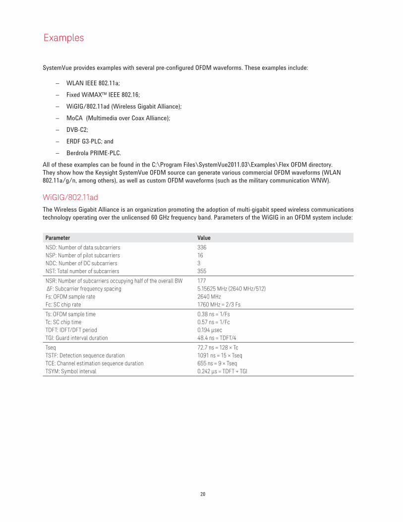
WiGIG/802.11ad
The Wireless Gigabit Alliance is an organization promoting the adoption of multi-gigabit speed wireless communications
technology operating over the unlicensed 60 GHz frequency band. Parameters of the WiGIG in an OFDM system include:
Parameter Value
NSD: Number of data subcarriers
NSP: Number of pilot subcarriers
NDC: Number of DC subcarriers
NST: Total number of subcarriers
336
16
3
355
NSR: Number of subcarriers occupying half of the overall BW
ΔF: Subcarrier frequency spacing Fs: OFDM sample rate
Fc: SC chip rate
177
5.15625 MHz (2640 MHz/512) 2640 MHz1760 MHz = 2/3 Fs
Ts: OFDM sample time
Tc: SC chip time
TDFT: IDFT/DFT period TGI: Guard interval duration
0.38 ns = 1/Fs0.57 ns = 1/Fc0.194 µsec48.4 ns = TDFT/4
Tseq
TSTF: Detection sequence duration
TCE: Channel estimation sequence duration
TSYM: Symbol interval
72.7 ns = 128 × Tc
1091 ns = 15 × Tseq655 ns = 9 × Tseq0.242 μs = TDFT + TGI
21
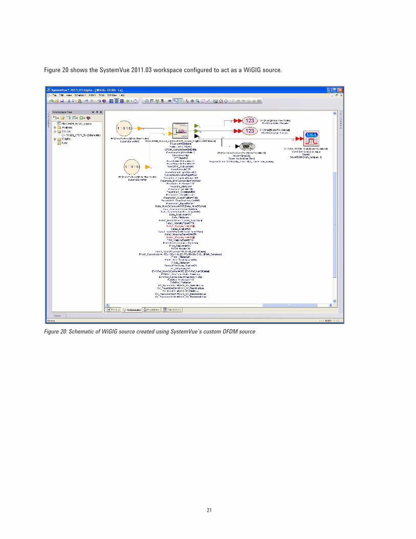
Figure 20 shows the SystemVue 2011.03 workspace configured to act as a WiGIG source.
Figure 20: Schematic of WiGIG source created using SystemVue’s custom OFDM source
22
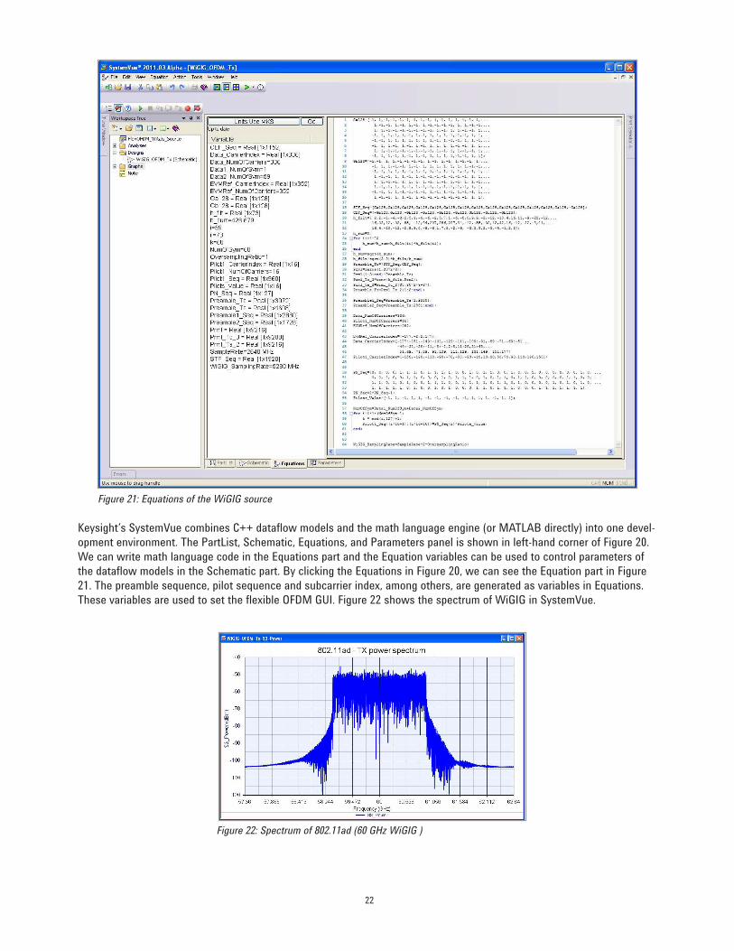
Figure 21: Equations of the WiGIG source
Keysight’s SystemVue combines C++ dataflow models and the math language engine (or MATLAB directly) into one devel-
opment environment. The PartList, Schematic, Equations, and Parameters panel is shown in left-hand corner of Figure 20.
We can write math language code in the Equations part and the Equation variables can be used to control parameters of
the dataflow models in the Schematic part. By clicking the Equations in Figure 20, we can see the Equation part in Figure
21. The preamble sequence, pilot sequence and subcarrier index, among others, are generated as variables in Equations.
These variables are used to set the flexible OFDM GUI. Figure 22 shows the spectrum of WiGIG in SystemVue.
Figure 22: Spectrum of 802.11ad (60 GHz WiGIG )
23
MoCA
MoCA is the universal standard for home entertainment networking. It is the only home entertainment networking
standard that appeals to all three pay TV segments – cable, satellite and Internet Protocol Television (IPTV). The current
MoCA specification can support multiple streams of HD video, deliver up to 175-Mbps net throughput and offer an
unparalleled user experience via parameterized quality of service (PQoS).
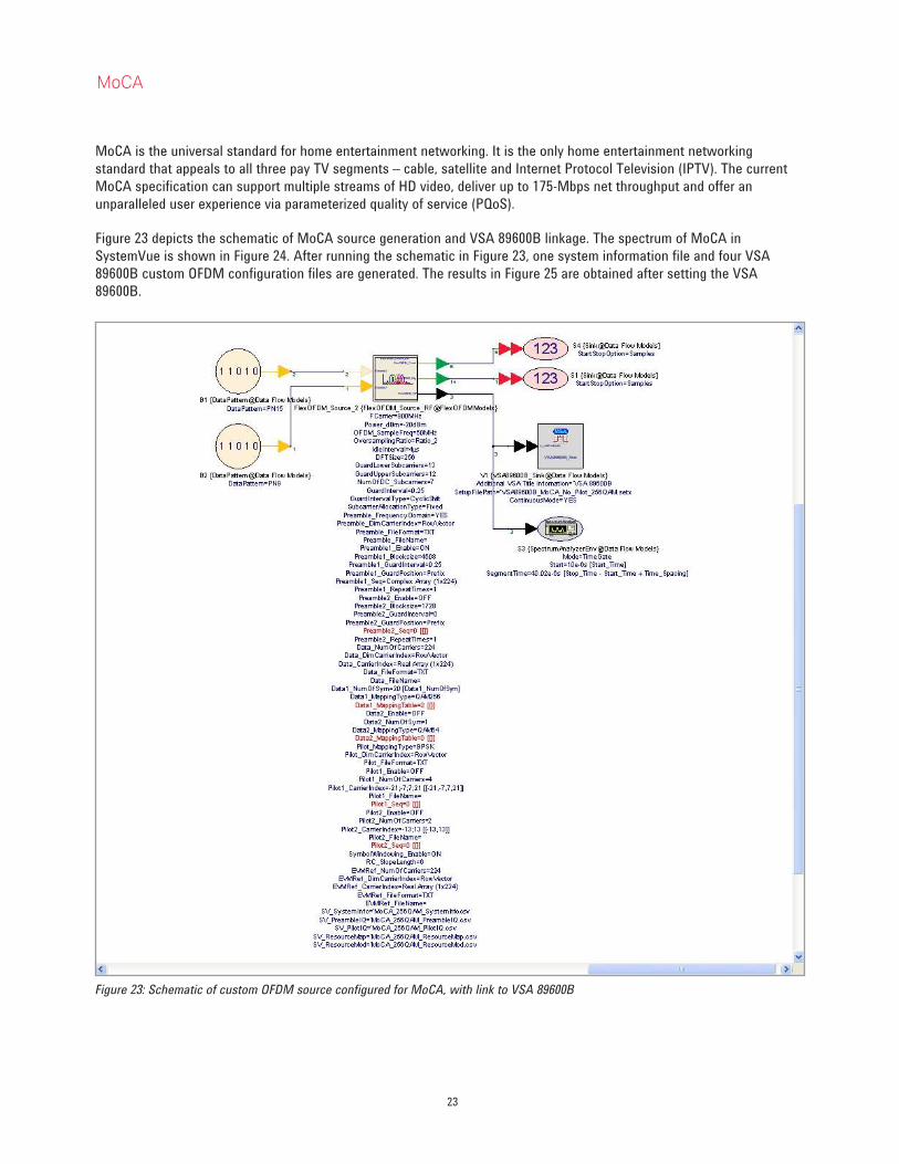
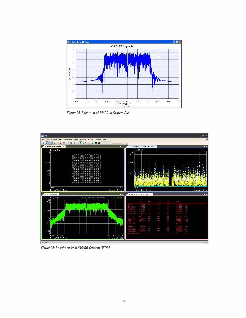
Figure 23 depicts the schematic of MoCA source generation and VSA 89600B linkage. The spectrum of MoCA in
SystemVue is shown in Figure 24. After running the schematic in Figure 23, one system information file and four VSA
89600B custom OFDM configuration files are generated. The results in Figure 25 are obtained after setting the VSA
89600B.
Figure 23: Schematic of custom OFDM source configured for MoCA, with link to VSA 89600B
24
Figure 24: Spectrum of MoCA in SystemVue
Figure 25: Results of VSA 89600B Custom OFDM
25
Summary
OFDM technology is a key enabling technique for wideband and emerging communication systems. The SystemVue OFDM
source capability can generate a variety of OFDM waveforms to meet custom requirements, as well as standard-compliant
waveforms. The SystemVue OFDM source also can be demodulated by Keysight’s VSA 89600B software using the
platform’s custom OFDM demodulation personality. This application note covered the basics of how to generate custom
OFDM waveforms using SystemVue. It also detailed how to link with the VSA 89600B software to create a complete
design-to-test capability for these complex systems.
“WiMAX,” “Fixed WiMAX,” “Mobile WiMAX,” “WiMAX Forum,” the WiMAX Forum logo, “WiMAX Forum Certified,” and
the WiMAX Forum Certified logo are trademarks of the WiMAX Forum. All other trademarks are the properties of their
respective owners.
References
1. IEEE 802.11, Supplement to Standard for Telecommunications and Information Exchange Between Systems-LAN/MAN Specific
Requirements - Part 11: Wireless MAC and PHY Specifications: High Speed Physical Layer in the 5 GHz Band, P802.11a, Dec. 1999.
2. IEEE 802.11n-2009, Supplement to Standard for Telecommunications and Information Exchange Between Systems-LAN/MAN
Specific Requirements - Part 11: Wireless LAN Medium Access Control (MAC) and Physical Layer (PHY) Specifications, Amendment
5: Enhancements for Higher Throughput, 2009.
3. IEEE 802.16-2004, IEEE Standard for Local and Metropolitan Area Networks - Part 16: Air Interface for Fixed Broadband Wireless
Access Systems, Oct. 2004.
4. IEEE P802.16e/D8, Amendment for Physical and Medium Access Control Layers for Combined Fixed and Mobile Operation in
Licensed Bands, May 2005.
5. IEEE P802.16-2004/Cor1/D3, Corrigendum to IEEE Standard for Local and Metropolitan Area Networks - Part 16: Air Interface for
Fixed Broadband Wireless Access Systems, May 2005.
6. ARIB STD-B31 Version 1.5, “Transmission System for Digital Terrestrial Television Broadcasting,” July 29, 2003.
7. ETSI EN300 744 v1.5.1, “Digital Video Broadcasting (DVB); Framing structure, channel coding and modulation for digital terrestrial
television.” European Telecommunication Standard, Nov. 2004.
8. ETSI EN 302 755: “Digital Video Broadcasting (DVB); Frame structure channel coding and modulation for a second generation digital
terrestrial television broadcasting system (DVB-T2).”
9. ETSI EN 302 769 V1.1.1 (2010-04): “Digital Video Broadcasting (DVB); Frame structure channel coding and modulation for a second
generation digital transmission system for cable systems (DVB-C2).”
10. http://www.erdfdistribution.fr/medias/Linky/PLC_G3_Physical_Layer_Specification.pdf
11. I. Berganza, A. Sendin and J. Arriola, “PRIME: powerline intelligent metering evolution,” CIRED Seminar, pp. 1-3, June 2008.
12. PRIME Project, PRIME Technology Whitepaper, July 2008,
http://www.iberdrola.es/webibd/gc/prod/en/doc/MAC_Spec_white_paper_1_0_080721.pdf.
13. WGA, Inc. Draft Specification D0.9r1, Mar. 2010.
14. PHY/MAC Complete Proposal Specification (approved as TGad D0.1 on May 20, 2010), 10433r2 at http://www.ieee802.org/11/
Reports/tgad_update.htm.
15. Shlomo Ovadia, Home Networking On Coax for Video and Multimedia: Overview for IEEE 802.1AVB, www.MoCAlliance.org,
May 2007.
16. Keysight 89600 Vector Signal Analyzer flexible OFDM Analysis Option BHF.
For more information about SystemVue, please visit us on the web:
Product information
http://www.keysight.com/find/eesof-systemvue
Product Conigurations http://www.keysight.com/find/eesof-systemvue-configs
Request a 30-day Evaluation
http://www.keysight.com/find/eesof-systemvue-evaluation
Downloads
http://www.keysight.com/find/eesof-systemvue-latest-downloads
Helpful Videos
http://www.keysight.com/find/eesof-systemvue-videos
Technical Support Forum
http://www.keysight.com/find/eesof-systemvue-forum
For more information on Keysight
Technologies’ products, applications or
services, please contact your local Keysight
office. The complete list is available at:
www.keysight.com/find/contactus
Americas
Canada (877) 894 4414Brazil 55 11 3351 7010Mexico 001 800 254 2440United States (800) 829 4444
Asia PaciicAustralia 1 800 629 485China 800 810 0189Hong Kong 800 938 693India 1 800 112 929Japan 0120 (421) 345Korea 080 769 0800Malaysia 1 800 888 848Singapore 1 800 375 8100Taiwan 0800 047 866Other AP Countries (65) 6375 8100
Europe & Middle East
Austria 0800 001122Belgium 0800 58580Finland 0800 523252France 0805 980333Germany 0800 6270999Ireland 1800 832700Israel 1 809 343051Italy 800 599100Luxembourg +32 800 58580Netherlands 0800 0233200Russia 8800 5009286Spain 0800 000154Sweden 0200 882255Switzerland 0800 805353
Opt. 1 (DE)Opt. 2 (FR)Opt. 3 (IT)
United Kingdom 0800 0260637
For other unlisted countries:
www.keysight.com/find/contactus
(BP-07-10-14)
This information is subject to change without notice.© Keysight Technologies, 2010-2014Published in USA, July 31, 20145990-6998ENwww.keysight.com
26 | Keysight | Custom OFDM Signal Generation Using SystemVue - Application Note


![Hard Decision-Based PWM for MIMO-OFDM Radar · 2. MIMO-OFDM Radar Signal Model-Based PWM 2.1. MIMO-OFDM Radar Systems Structure In [1], OFDM technique has the advantage of combating](https://img.pdfslide.us/doc/110x75/5e6a685a5002aa073940e3bf/hard-decision-based-pwm-for-mimo-ofdm-radar-2-mimo-ofdm-radar-signal-model-based.jpg)