Embed Size (px)
Citation preview
Administrative Changes to AFH 10-222, Volume 11, Contingency Water System Installation and
Operation
OPR: AFCEC/CXX
References throughout to “HQ AFCESA/CEXX” are hereby changed to “AFCEC/CXX.”
Delete reference throughout to “AFI 10-211, Civil Engineer Contingency Response Planning.”
References throughout to “Air Force Doctrine Document (AFDD)” are hereby changed to “Air
Force Doctrine Annex (AFDA).”
References throughout to “Air Force Civil Engineer Support Agency (AFCESA)” are hereby
changed to “Air Force Civil Engineer Center (AFCEC).”
Delete reference throughout to “AFH 10-222, Volume 9, Guide to Reverse Osmosis Water
Purification Unit Installation and Operation.”
Delete Term for “Air Force Civil Engineer Support Agency (AFCESA).”
31 MAY 2016

CONTINGENCY WATER SYSTEM INSTALLATION AND
OPERATION
AIR FORCE HANDBOOK 10-222, VOLUME 11
19 May 2011
DEPARTMENT OF THE AIR FORCE
BY ORDER OF THE AIR FORCE HANDBOOK 10-222
SECRETARY OF THE AIR FORCE VOLUME 11
19 May 2011
Operations
CONTINGENCY WATER SYSTEM
INSTALLATION AND OPERATION
ACCESSIBILITY: Publications and forms are available on the e-Publishing
website at www.e-publishing.af.mil for downloading or ordering.
RELEASABILITY: There are no releasability restrictions on this publication.
OPR: AFCESA/CEXX Certified by: AF/A7CX (Colonel Jeffery A. Vinger)
Pages: 154
This handbook provides USAF civil engineers with guidance on the
installation and use of Air Force contingency water systems. It addresses site
location and layout, assembly, and operation of water system components at
bare base or austere locations. When coupled with information contained in
applicable technical orders, Air Force Pamphlet (AFPAM) 10-219, Volume
5, Bare Base Conceptual Planning Guide, and instruction received at Silver
Flag training sites, personnel should be able to effectively set up and operate
all components of the water system. This publication applies to all Air Force
active duty, Air National Guard (ANG), and Air Force Reserve Command
Civil Engineer units. It supports Air Force Instruction (AFI) 10-210, Prime
Base Engineer Emergency Force (BEEF) Program, and AFI 10-211, Civil
Engineer Contingency Response Planning. Refer recommended changes
and questions about this publication to the O ffice of Primary
Responsibility (O PR) using AF Form 8 4 7 , Recommendation for Change
of Publication; route AF Form 8 4 7 from the field through the
appropriate functional chain of command and Major Command
(MAJCO M) publications/ forms managers. Ensure that all records created
as a result of processes prescribed in this publication are maintained in
Certified Current 4 May 2015
AFH 10-222 Volume 11, 19 May 2011
2
accordance with Air Force Manual (AFMAN) 33-363, Management of
Records, and disposed of in accordance with Air Force Records Disposition
Schedule (RDS) located at https://www.my.af.mil/gcss-af61a/afrims/afrims/.
The use of the name or mark of any specific manufacturer, commercial
product, commodity, or service in this publication does not imply
endorsement by the Air Force.
Chapter 1—INTRODUCTION .................................................................... 9
1.1. Scope ......................................................................................... 9
1.2. Overview ................................................................................... 9
1.3. General Information .................................................................. 9
Figure 1.1. Air Force Civil Engineer Publications Hierarchy .................. 10
1.4. Water System Design and Capacity ........................................ 11
Figure 1.2. Color-Coding of Subsystem Components .............................. 11
Figure 1.3. Contingency Water Subsystems ............................................. 12
1.5. Safety ...................................................................................... 13
1.6. Additional Information ............................................................ 13
Chapter 2—PLANNING AND PREPARATION ..................................... 14
2.1. General Information ................................................................ 14
2.2. Site Selection ........................................................................... 14
2.3. Layout ..................................................................................... 14
Figure 2.1.Illustration of Subsystems within a WOA .............................. 15
Table 2.1. WOA Layout Dimensions and Water Production Subsystems16
Figure 2.2. Location of WOA (Typical) ................................................... 16
2.4. Equipment Preparation ............................................................ 17
Figure 2.3. Heavy Equipment Needed to Preposition Water Subsystems 17
2.5. System Flexibility ................................................................... 17
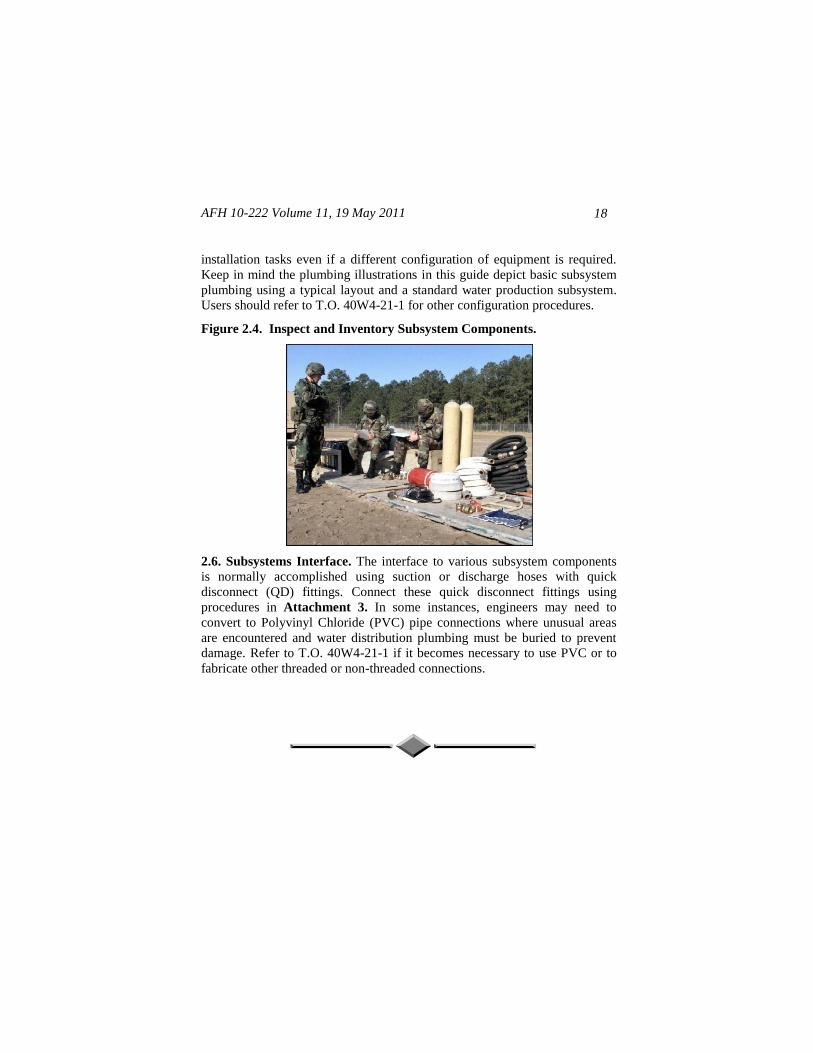
Figure 2.4. Inspect and Inventory Subsystem Components ..................... 18
2.6. Subsystems Interface ............................................................... 18
AFH 10-222 Volume 11, 19 May 2011 3
Chapter 3—SOURCE RUN SUBSYSTEM .............................................. 19
3.1. General Information ................................................................ 19
3.2. Components ............................................................................ 19
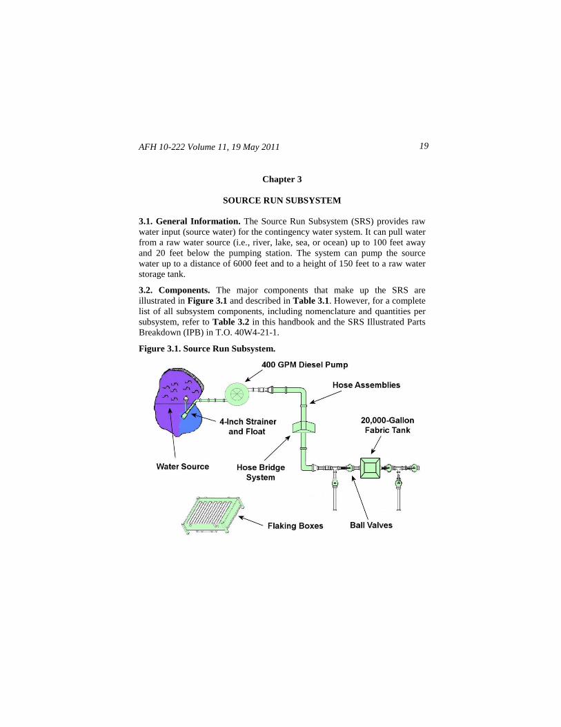
Figure 3.1. Source Run Subsystem .......................................................... 19
Table 3.1. SRS Major Components ......................................................... 20
3.3. Installation ............................................................................... 21
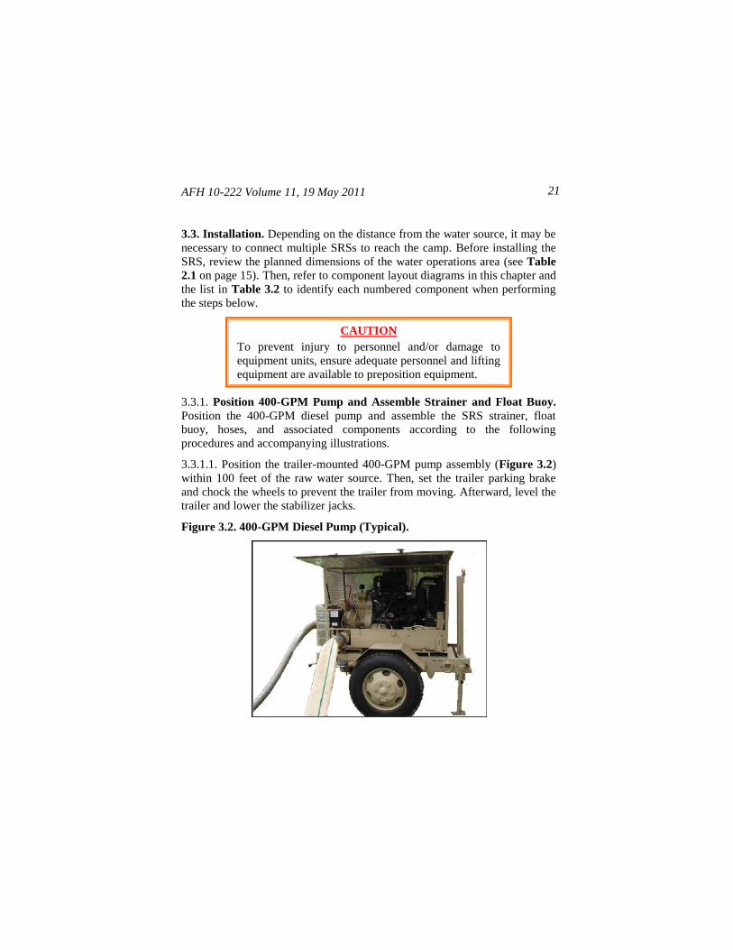
Figure 3.2. 400-GPM Diesel Pump (Typical) .......................................... 21
Figure 3.3. Positioning Float Buoy, Strainer, and Anchor ....................... 22
Figure 3.4. Strainer, Float Buoy, and Pump Inlet Component Layout ..... 23
Figure 3.5. Pump Outlet and 20,000-Gallon Tank Component Layout ... 24
Figure 3.6. SRS Tank Placement In WOA (Typical) ............................... 25
Figure 3.7. 20,000-Gallon Raw Water Tank ............................................ 25
Figure 3.8. 400-GPM Pump Connections ................................................ 26
Figure 3.9. Deploying 6-Inch Hose from Flaking Boxes ......................... 27
3.4. Operation ................................................................................. 27
3.5. Component Descriptions ......................................................... 28
Table 3.2. SRS Component Description and Item Number .................... 28
Chapter 4—WATER PRODUCTION SUBSYSTEM ............................. 31
4.1. General Information ................................................................ 31
Figure 4.1. 1500 ROWPU ........................................................................ 31
Figure 4.2. 600 ROWPU .......................................................................... 32
4.2. Components ............................................................................ 32
Table 4.1. WPS Major Components ....................................................... 32
Figure 4.3. WPS Illustration Using Three ROWPUs ............................... 34
4.3. Installation ............................................................................... 34
Figure 4.4. Location of WOA Water Tanks and ROWPUs (Typical) ...... 35
AFH 10-222 Volume 11, 19 May 2011
4
Figure 4.5. WPS and SRS Raw Water Tank Connections (Typical) ........ 36
Figure 4.6. Raw Water Hoses and Component Layout ............................ 37
Figure 4.7. Brine Hoses and Component Layout ..................................... 38
Figure 4.8. Wastewater Hoses and Component Layout ........................... 40
Figure 4.9. Potable Water Hoses and Component Layout........................ 41
Figure 4.10. Erecting a Potable Water Tank Farm ................................... 42
4.4. Operation ................................................................................. 43
4.5. WPS Component Descriptions ................................................ 45
Table 4.2. WPS Component Description and Item Number ................... 45
Chapter 5—550-INITIAL SUBSYSTEM.................................................. 51
5.1. General Information ................................................................ 51
5.2. Components ............................................................................ 51
Figure 5.1. 550-Initial Subsystem ............................................................ 52
Table 5.1. 550-Initial Subsystem Major Components ............................. 53
5.3. Installation ............................................................................... 54
Figure 5.2. Siting Dual Pump Station and 20,000-Gallon Tanks (Typical) 55
Figure 5.3. 550-Initial Subsystem Dual Pump Station and 20,000-
Gallon Potable Water Tanks Basic Component Layout .... 56
Figure 5.4. Sewage Ejector System Placement (Typical)......................... 57
Figure 5.5. 3,000-Gallon Potable Water Tank at User Facility ................ 58
Figure 5.6. Potable Water Distribution Loop Starting Point ................... 59
Figure 5.7. Water Distribution Loop Component Layout ....................... 60
Figure 5.8. Inlet Connections for 3,000-Gallon Facility Tanks ............... 61
Figure 5.9. Bladder Water Level Controller Connections (Typical) ........ 61
Figure 5.10. 3,000-Gallon Tank Outlet Connections (Shower/Latrine) ... 62
Figure 5.11. 3,000-Gallon Tank Outlet Connections (Laundry) .............. 63
Figure 5.12. 3,000-Gallon Tank Outlet Connections (Kitchen) ............... 63
AFH 10-222 Volume 11, 19 May 2011 5
Figure 5.13. Closed Water Distribution Loop (Typical) .......................... 64
Figure 5.14. Wastewater Lift Stations and Tank Component Layout ..... 65
Figure 5.15. Macerator Pump Lift Station ............................................... 67
Figure 5.16. Dual Pump Lift Station ....................................................... 68
Figure 5.17. 25,000-Gallon Wastewater Collection Tank ........................ 69
Figure 5.18. Extension Spring .................................................................. 70
Figure 5.19. Three Positioning Cables Attached to Outside Wall ............ 71
Figure 5.20. Configuration of Wastewater Tank and Mixing System ...... 72
Figure 5.21. Circulation Pump Positioned Below Circulation Manifold . 72
Figure 5.22. Shower and Laundry Waste Hose Component Layout ....... 73
Figure 5.23. Latrine Waste Hose Component Layout .............................. 74
Figure 5.24. Dual Pump Lift Station Inlet/Outlet Component Layout ..... 76
5.4. Operation ................................................................................. 76
Table 5.2. 550-Initial Subsystem Preoperational Checks ........................ 77
Figure 5.25. Maximum Fill Height (20,000-Gallon Bladder) .................. 80
Figure 5.26. Access Door on Chlorine Feed Tank ................................... 81
Figure 5.27. Dual Pumping Station Control Panel .................................. 82
Figure 5.28. Feed Pump Control Panel ................................................... 83
Figure 5.29. Prime Assist Valve (Priming Knob) .................................... 84
Figure 5.30. Pump Vent Plugs.................................................................. 84
Figure 5.31. Sample Water Ball Valve ..................................................... 85
Figure 5.32. Bladder Water Level Controls ............................................. 86
Table 5.3. Bladder Water Level Controller—Controls and Indicators .... 87
Figure 5.33. Macerator Pump Lift Station Control Box ........................... 88
Figure 5.34. Dual Pump Lift Station Control Box ................................... 89
5.5. Component Descriptions ......................................................... 90
AFH 10-222 Volume 11, 19 May 2011
6
Table 5.4. 550-Initial Component Description and Item Number ........... 90
Chapter 6—550-FOLLOW-ON SUBSYSTEM ........................................ 96
6.1. General Information ................................................................ 96
Figure 6.1. User Facilities (Typical) ........................................................ 96
6.2. Components ............................................................................ 96
Figure 6.2. 550-Follow-On Subsystem .................................................... 97
Table 6.1. 550-Follow-On Subsystem Major Components ..................... 98
6.3. Installation ............................................................................... 99
Figure 6.3. Initial Tank Farm Configuration (Typical) ............................ 99
Figure 6.4. 550-Follow-On Subsystem 20,000-Gallon Tank Alignment 100
Figure 6.5. Location of 20,000-Gallon Tank Connections ..................... 100
Figure 6.6. Assembly of 20,000-Gallon Tank Outlet Branches ............. 101
Figure 6.7. Tank Farm Isolation and Insertion of 550F Tank Outlet
Tees ...................................................................................... 102
Figure 6.8. Assembly of 20,000-Gallon Tank Inlet Branches ................ 103
Figure 6.9. Assembly of Water Feed Inlet Lines for Follow-On Tanks . 104
Figure 6.10. Positioning Ball Valves to Fill 550F Tanks and Recharge
Distribution Loop Using WPS and 550I Tanks .................. 105
Figure 6.11. Sewage Ejector System Installed Next to Latrine Facility . 106
Figure 6.12. Placement of 3,000-Gallon Potable Water Tanks (Typical)107
Figure 6.13. Expanded Water Distribution Loop Component Layout ... 109
Figure 6.14. Inlet Connections for 3,000-Gallon Facility Tanks ............ 110
Figure 6.15. 3,000-Gallon Tank Outlet Connections (Shower/Latrine) . 111
Figure 6.16. 3,000-Gallon Tank Outlet Connections (Laundry) ............ 111
Figure 6.17. 3,000-Gallon Tank Outlet Connections (Kitchen) ............. 112
Figure 6.18. Placement of Macerator Pump Lift Station (Typical) ........ 113
Figure 6.19. Installed Macerator Pump Lift Station ............................... 114
AFH 10-222 Volume 11, 19 May 2011 7
Figure 6.20. Shower and Laundry Waste Hose Component Layout ...... 115
Figure 6.21. Latrine Wastewater Hose Component Layout ................... 116
Figure 6.22. Kitchen Wastewater Hose Component Layout .................. 117
Figure 6.23. Wastewater Distribution Hose and Component Layout 1 .. 118
Figure 6.24. Wastewater Distribution Hose and Component Layout 2 .. 119
6.4. Operation ............................................................................... 120
Table 6.2. 550-Follow-On Subsystem Preoperational Checks .................. 121
6.5. Component Descriptions ....................................................... 124
Table 6.3. 550-Follow-On Component Description and Item Number . 124
Chapter 7— INDUSTRIAL OPERATIONS AND FLIGHTLINE
EXTENSION SUBSYSTEM ............................................... 130
7.1. General Information .............................................................. 130
7.2. Components .......................................................................... 130
Table 7.1. Industrial Operations and Flightline Extension Subsystem
Major Components............................................................... 130
Figure 7.1. Industrial Operations and Flightline Extension Subsystem . 131
7.3. Installation ............................................................................. 131
Figure 7.2. Extension Subsystem Potable Water Loop Connections ..... 132
Figure 7.3. Pump Placement and Connections Layout ........................... 133
Figure 7.4. Extension Subsystem User-Facility Connections ................ 134
7.4. Operation ............................................................................... 135
Table 7.2. Industrial Operations and Flightline Extension Subsystem
Preoperational Checks ......................................................... 135
7.5. Component Descriptions ....................................................... 137
Table 7.3. Industrial Operations and Flightline Extension Subsystem
Component Description and Item Number .......................... 137

AFH 10-222 Volume 11, 19 May 2011
8
Attachment 1—GLOSSARY OF REFERENCES AND SUPPORTING
INFORMATION ............................................................ 141
Attachment 2—COMPONENTS ILLUSTRATIONS ........................... 145
Attachment 3—HOSE QUICK- DISCONNECT (QD) COUPLING
CONNECTIONS ............................................................ 149
Attachment 4—HOSE BRIDGE SYSTEM ASSEMBLY ...................... 151
Attachment 5—NORMAL OPERATION OF THE CONTINGENCY
WATER SYSTEM ......................................................... 152

AFH 10-222 Volume 11, 19 May 2011 9
Chapter 1
INTRODUCTION
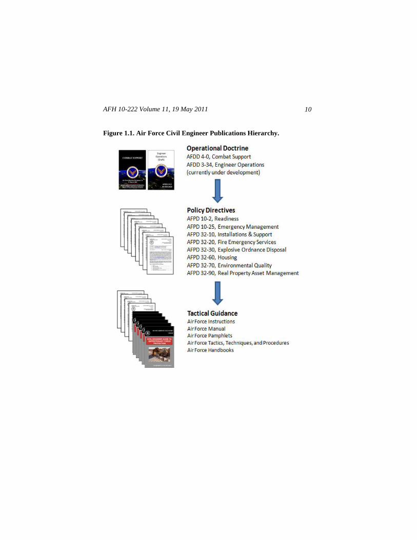
1.1. Scope. This handbook augments, but does not replace information
contained in technical orders for contingency water systems and subsystems.
Users should refer to applicable technical orders for all warnings and cautions
and complete assembly, maintenance, operation, and troubleshooting
information. Civil engineer (CE) tactics, techniques, and procedures (TTPs)
in this handbook supports precepts outlined in Air Force Doctrine Document
(AFDD) 4-0, Combat Support, and other published guidance related to
Engineer Operations. They also supports implementation of Air Force Policy
Directive (AFPD) 10-2, Readiness. This relationship is illustrated in Figure
1.1, the Air Force CE hierarchy of publications.
1.2. Overview. This handbook addresses general characteristics, setup, and
basic operating procedures for the contingency water system and targets civil
engineer utilities personnel while performing their beddown and sustainment
mission taskings under contingency conditions. Users without a fundamental
knowledge of this water system should also review the references in
Attachment 1.
1.3. General Information. The contingency water system fulfills potable
water and wastewater recovery needs at austere locations. The water system
provides water to support kitchens, latrines, showers, laundries, and other
bare base facilities and recovers the wastewater for appropriate disposal. The
system is semi-automatic in that the 3,000-gallon facility storage tanks will
fill automatically as long as the manually filled 20,000-gallon storage tanks
are kept at the appropriate level. Once the system has been filled to capacity,
water should be available for 5 days given 30 gallons per person per day
usage. The removal of facility wastewater is also automatic under normal
circumstances and does not require manual intervention.
AFH 10-222 Volume 11, 19 May 2011
10
Figure 1.1. Air Force Civil Engineer Publications Hierarchy.
AFH 10-222 Volume 11, 19 May 2011 11
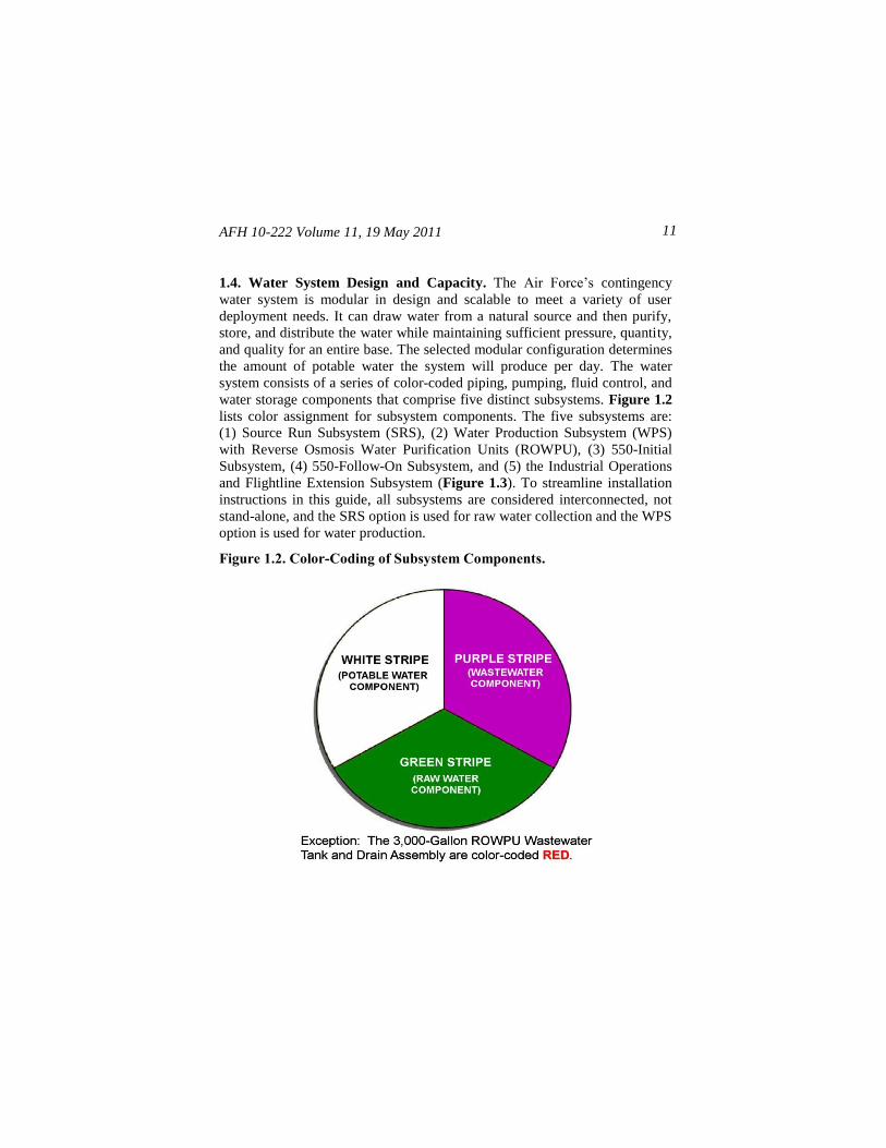
1.4. Water System Design and Capacity. The Air Force’s contingency
water system is modular in design and scalable to meet a variety of user
deployment needs. It can draw water from a natural source and then purify,
store, and distribute the water while maintaining sufficient pressure, quantity,
and quality for an entire base. The selected modular configuration determines
the amount of potable water the system will produce per day. The water
system consists of a series of color-coded piping, pumping, fluid control, and
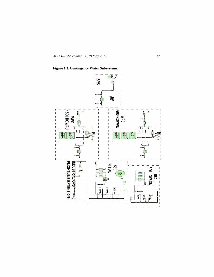
water storage components that comprise five distinct subsystems. Figure 1.2
lists color assignment for subsystem components. The five subsystems are:
(1) Source Run Subsystem (SRS), (2) Water Production Subsystem (WPS)
with Reverse Osmosis Water Purification Units (ROWPU), (3) 550-Initial
Subsystem, (4) 550-Follow-On Subsystem, and (5) the Industrial Operations
and Flightline Extension Subsystem (Figure 1.3). To streamline installation
instructions in this guide, all subsystems are considered interconnected, not
stand-alone, and the SRS option is used for raw water collection and the WPS
option is used for water production.
Figure 1.2. Color-Coding of Subsystem Components.
AFH 10-222 Volume 11, 19 May 2011
12
Figure 1.3. Contingency Water Subsystems.
AFH 10-222 Volume 11, 19 May 2011 13
1.5. Safety. All personnel must practice proper safety procedures when
setting up and operating water systems. Individuals should guard against
electrical, fire, tripping, and falling hazards. In particular, flammable fuels,
hazardous chemicals, and lethal voltages used in the operation of some water
system components are considerable hazards, and failure to comply with
technical order warnings could result in injury or death. Review procedures in
AFI 32-1064, Electrical Safe Practices, when dealing with lethal voltages. It
is also important to protect against other water system hazards such as highly
pressurized subsystems and components, harmful solvents and adhesives, and
infectious black and gray water products. Be sure to wear appropriate
personal protective equipment (PPE) according to applicable technical
information and standards.
1.6. Additional Information. Users should refer to Technical Order (T.O.)
40W4-21-1, Basic Expeditionary Airfield Resources (BEAR) Water System,
for additional information such as unpacking, preparation for use, safety, as-
sembly, operation, and maintenance instructions. In addition, contact the Air
Force Civil Engineer Support Agency (AFCESA) Reach-Back Center when
looking for information not found in this publication or references in At-
tachment 1. Contact the Reach-Back Center at 888-232-3721 (commercial),
DSN 523-6995, or email at [email protected].
AFH 10-222 Volume 11, 19 May 2011
14
Chapter 2
PLANNING AND PREPARATION
2.1. General Information. The installation and use of contingency water
subsystems vary from location to location and depend a great deal on the
terrain features and the type and quantity of users. Since potential locations or
sites may not need every available contingency water subsystem, the modular
design of the water system allows planners to select specific subsystems
based on the needs of the installation.
2.2. Site Selection. Before engineer work crews can begin constructing an
installation’s contingency water system, planners need to determine the site
location, equipment prepositioning requirements, size of the camp supported,
and whether there is access to an adequate water source to sustain operations.
Plans should be detailed enough to enable a work crew to off-load selected
subsystems at the designated location and assemble them in a minimum
amount of time. Planners should refer to AFPAM 10-219, Vol 5, Bare Base
Conceptual Planning Guide, for more information on siting contingency
water systems and other associated considerations. In addition, engineer
planners should take full advantage of Installation Geospatial Information and
Services (IGI&S) satellite imagery, global positioning system (GPS) data,
and common installation picture (CIP) databases, because these assets can
dramatically enhance their planning capabilities. Some of this information
can be accessed easily and securely through the Air Force Portal at the Air
Combat Command (ACC) IGI&S GeoBase web site. The web site is a good
resource for planning water systems in relation to camp layout, terrain, and
available water sources.
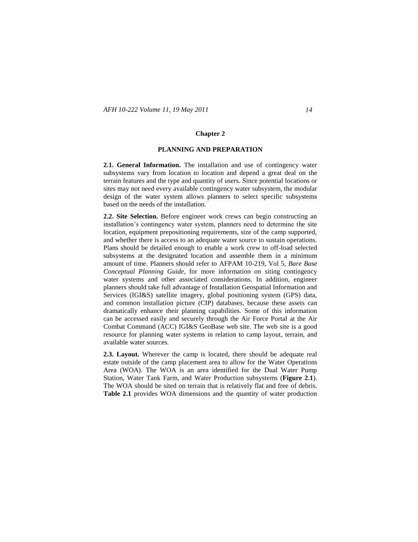
2.3. Layout. Wherever the camp is located, there should be adequate real
estate outside of the camp placement area to allow for the Water Operations
Area (WOA). The WOA is an area identified for the Dual Water Pump
Station, Water Tank Farm, and Water Production subsystems (Figure 2.1).
The WOA should be sited on terrain that is relatively flat and free of debris.
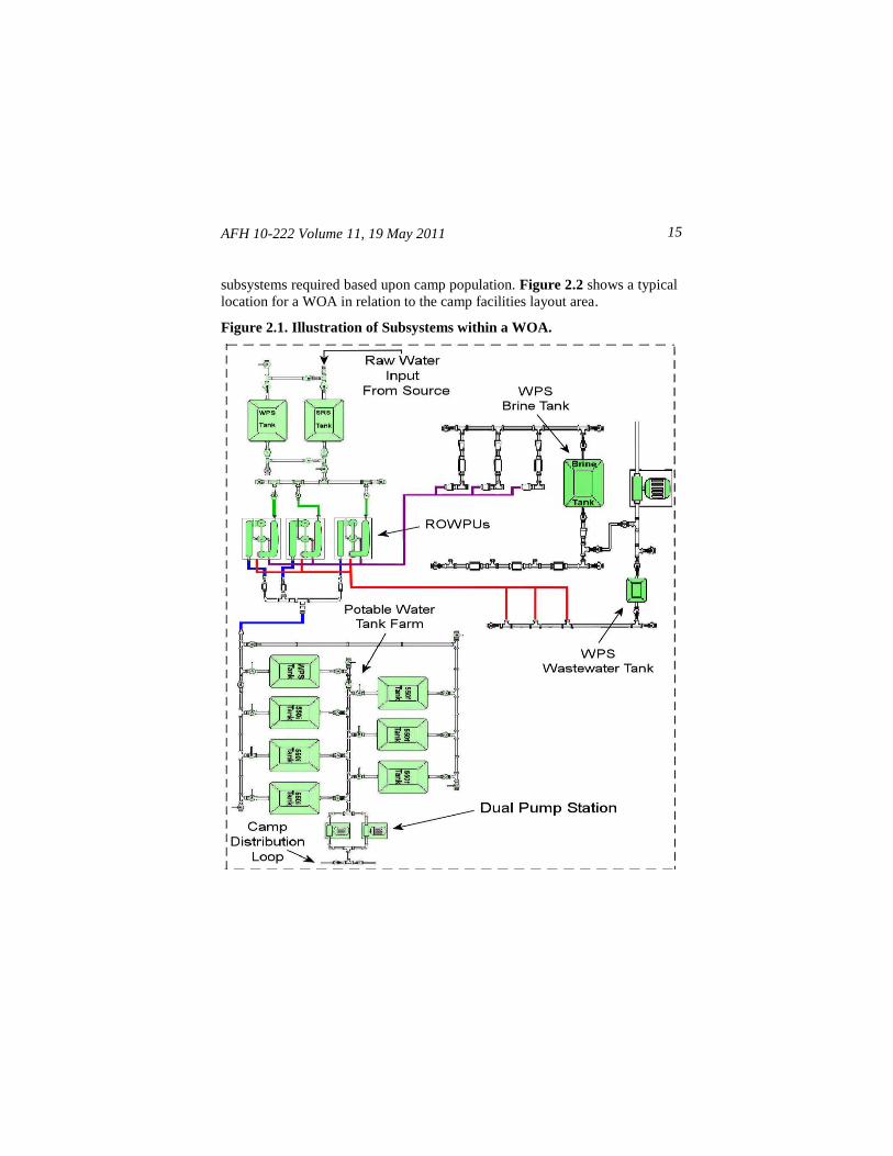
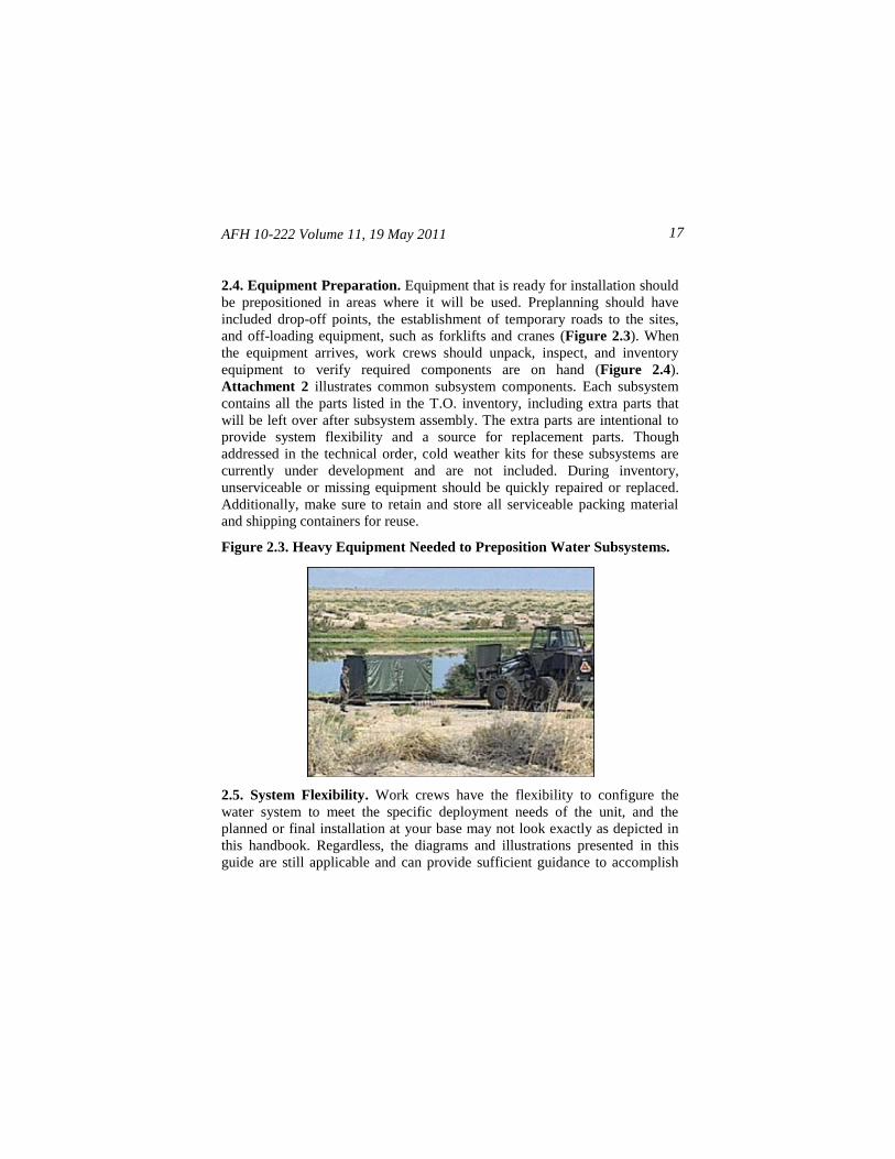
Table 2.1 provides WOA dimensions and the quantity of water production
AFH 10-222 Volume 11, 19 May 2011 15
subsystems required based upon camp population. Figure 2.2 shows a typical
location for a WOA in relation to the camp facilities layout area.
Figure 2.1. Illustration of Subsystems within a WOA.
AFH 10-222 Volume 11, 19 May 2011
16
Table 2.1. WOA Layout Dimensions and Water Production Subsystems.
Camp
Populace
Gallons
Required
Per Day
(30
GPPPD)
Tank
Farm (TF)
ONLY
Area in
Feet
(Width x
Length)
TF w/600
Water
Production
Subsystem
(WPS)
TF w/1500
Water
Production
Subsystem
(WPS)
600 WPS
Quantities
36,000
GPD (3 ROWPUs)
1500 WPS
Quantities
60,000
GPD (2 ROWPUs)
550 16,500 50 x 130 160 x 230 140 x 230 1 1
1100 33,000 80 x 130 160 x 230 140 x 230 1 1
1650 49,500 160 x 130 250 x 230 140 x 230 2 1
2200 66,000 160 x 160 250 x 260 210 x 260 2 2
2750 82,500 160 x 190 340 x 290 280 x 290 3 2
3300 99,000 160 x 190 340 x 290 280 x 290 3 2
4400 132,000 200 x 220 430 x 320 350 x 320 4 3
Figure 2.2. Location of WOA (Typical).
AFH 10-222 Volume 11, 19 May 2011 17
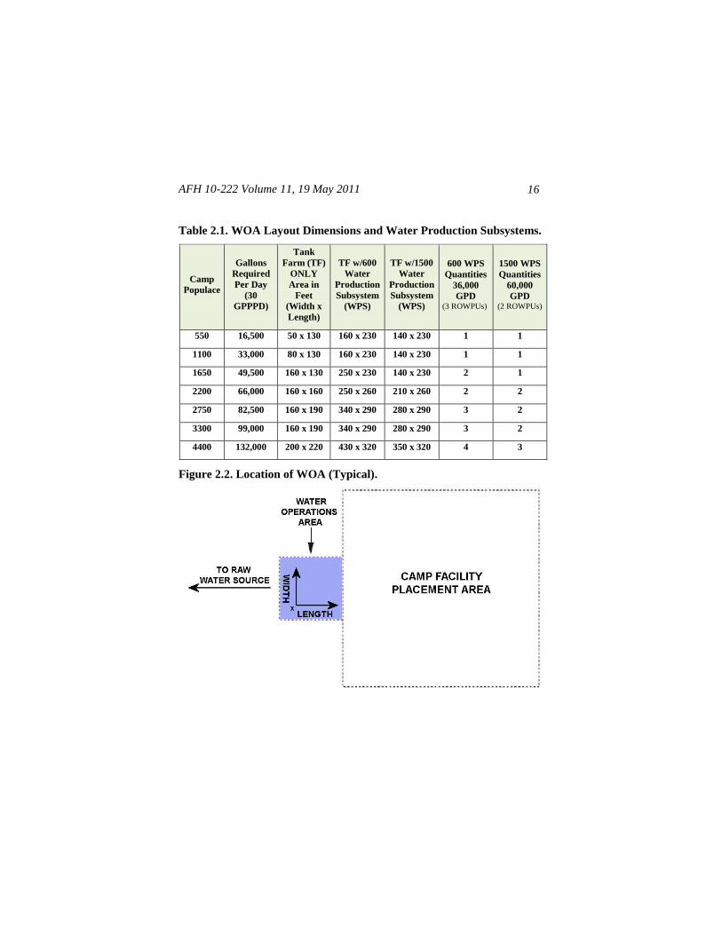
2.4. Equipment Preparation. Equipment that is ready for installation should
be prepositioned in areas where it will be used. Preplanning should have
included drop-off points, the establishment of temporary roads to the sites,
and off-loading equipment, such as forklifts and cranes (Figure 2.3). When
the equipment arrives, work crews should unpack, inspect, and inventory
equipment to verify required components are on hand (Figure 2.4).
Attachment 2 illustrates common subsystem components. Each subsystem
contains all the parts listed in the T.O. inventory, including extra parts that
will be left over after subsystem assembly. The extra parts are intentional to
provide system flexibility and a source for replacement parts. Though
addressed in the technical order, cold weather kits for these subsystems are
currently under development and are not included. During inventory,
unserviceable or missing equipment should be quickly repaired or replaced.
Additionally, make sure to retain and store all serviceable packing material
and shipping containers for reuse.
Figure 2.3. Heavy Equipment Needed to Preposition Water Subsystems.
2.5. System Flexibility. Work crews have the flexibility to configure the
water system to meet the specific deployment needs of the unit, and the
planned or final installation at your base may not look exactly as depicted in
this handbook. Regardless, the diagrams and illustrations presented in this
guide are still applicable and can provide sufficient guidance to accomplish
AFH 10-222 Volume 11, 19 May 2011
18
installation tasks even if a different configuration of equipment is required.
Keep in mind the plumbing illustrations in this guide depict basic subsystem
plumbing using a typical layout and a standard water production subsystem.
Users should refer to T.O. 40W4-21-1 for other configuration procedures.
Figure 2.4. Inspect and Inventory Subsystem Components.
2.6. Subsystems Interface. The interface to various subsystem components
is normally accomplished using suction or discharge hoses with quick
disconnect (QD) fittings. Connect these quick disconnect fittings using
procedures in Attachment 3. In some instances, engineers may need to
convert to Polyvinyl Chloride (PVC) pipe connections where unusual areas
are encountered and water distribution plumbing must be buried to prevent
damage. Refer to T.O. 40W4-21-1 if it becomes necessary to use PVC or to
fabricate other threaded or non-threaded connections.
AFH 10-222 Volume 11, 19 May 2011 19
Chapter 3
SOURCE RUN SUBSYSTEM
3.1. General Information. The Source Run Subsystem (SRS) provides raw
water input (source water) for the contingency water system. It can pull water
from a raw water source (i.e., river, lake, sea, or ocean) up to 100 feet away
and 20 feet below the pumping station. The system can pump the source
water up to a distance of 6000 feet and to a height of 150 feet to a raw water
storage tank.
3.2. Components. The major components that make up the SRS are
illustrated in Figure 3.1 and described in Table 3.1. However, for a complete
list of all subsystem components, including nomenclature and quantities per
subsystem, refer to Table 3.2 in this handbook and the SRS Illustrated Parts
Breakdown (IPB) in T.O. 40W4-21-1.
Figure 3.1. Source Run Subsystem.
AFH 10-222 Volume 11, 19 May 2011
20
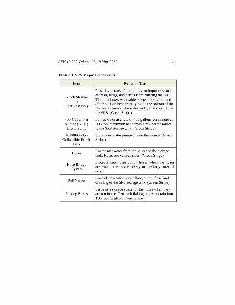
Table 3.1. SRS Major Components.
Item Function/Use
4-Inch Strainer
and
Float Assembly
Provides a coarse filter to prevent impurities such
as trash, twigs, and debris from entering the SRS.
The float buoy, with cable, keeps the strainer end
of the suction hose from lying on the bottom of the
raw water source where dirt and gravel could enter
the SRS. (Green Stripe)
400-Gallon Per
Minute (GPM)
Diesel Pump
Pumps water at a rate of 400 gallons per minute at
300-foot maximum head from a raw water source
to the SRS storage tank. (Green Stripe)
20,000-Gallon
Collapsible Fabric
Tank
Stores raw water pumped from the source. (Green
Stripe)
Hoses Routes raw water from the source to the storage
tank. Hoses are various sizes. (Green Stripe)
Hose Bridge
System
Protects water distribution hoses when the hoses
are routed across a roadway or similarly traveled
area.
Ball Valves Controls raw water input flow, output flow, and
draining of the SRS storage tank. (Green Stripe)
Flaking Boxes
Serve as a storage space for the hoses when they
are not in use. Ten each flaking boxes contain four
150-foot lengths of 6-inch hose.
AFH 10-222 Volume 11, 19 May 2011 21
3.3. Installation. Depending on the distance from the water source, it may be
necessary to connect multiple SRSs to reach the camp. Before installing the
SRS, review the planned dimensions of the water operations area (see Table
2.1 on page 15). Then, refer to component layout diagrams in this chapter and
the list in Table 3.2 to identify each numbered component when performing
the steps below.
3.3.1. Position 400-GPM Pump and Assemble Strainer and Float Buoy.
Position the 400-GPM diesel pump and assemble the SRS strainer, float
buoy, hoses, and associated components according to the following
procedures and accompanying illustrations.
3.3.1.1. Position the trailer-mounted 400-GPM pump assembly (Figure 3.2)
within 100 feet of the raw water source. Then, set the trailer parking brake
and chock the wheels to prevent the trailer from moving. Afterward, level the
trailer and lower the stabilizer jacks.
Figure 3.2. 400-GPM Diesel Pump (Typical).
CAUTION
To prevent injury to personnel and/or damage to
equipment units, ensure adequate personnel and lifting
equipment are available to preposition equipment.
AFH 10-222 Volume 11, 19 May 2011
22
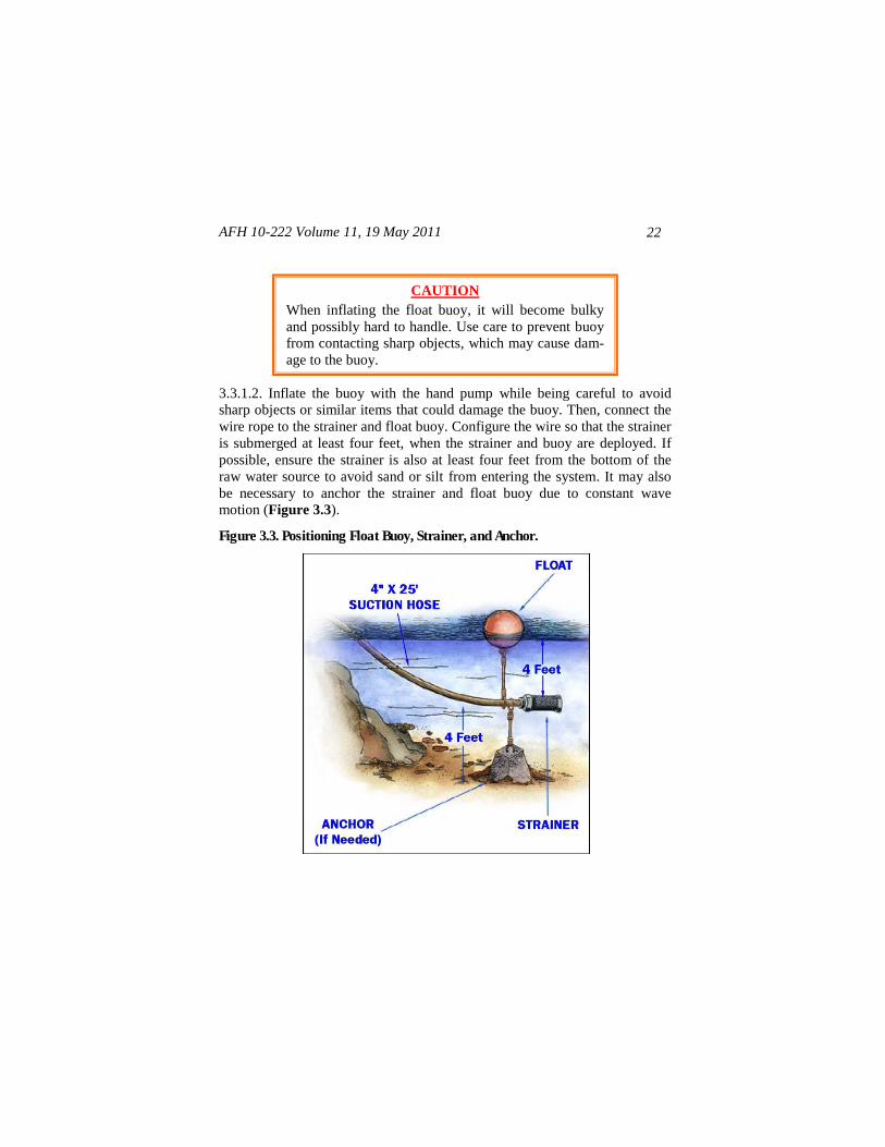
3.3.1.2. Inflate the buoy with the hand pump while being careful to avoid
sharp objects or similar items that could damage the buoy. Then, connect the
wire rope to the strainer and float buoy. Configure the wire so that the strainer
is submerged at least four feet, when the strainer and buoy are deployed. If
possible, ensure the strainer is also at least four feet from the bottom of the
raw water source to avoid sand or silt from entering the system. It may also
be necessary to anchor the strainer and float buoy due to constant wave
motion (Figure 3.3).
Figure 3.3. Positioning Float Buoy, Strainer, and Anchor.
CAUTION
When inflating the float buoy, it will become bulky
and possibly hard to handle. Use care to prevent buoy
from contacting sharp objects, which may cause dam-
age to the buoy.
AFH 10-222 Volume 11, 19 May 2011 23
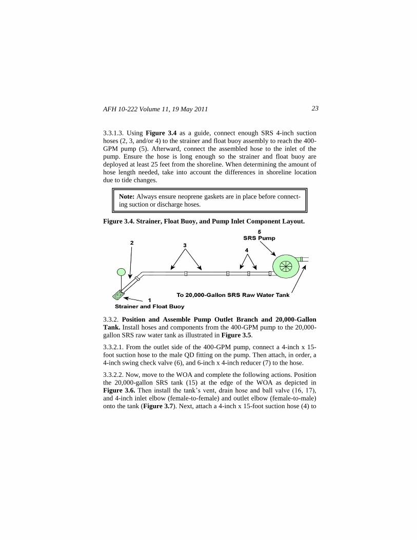
3.3.1.3. Using Figure 3.4 as a guide, connect enough SRS 4-inch suction
hoses (2, 3, and/or 4) to the strainer and float buoy assembly to reach the 400-
GPM pump (5). Afterward, connect the assembled hose to the inlet of the
pump. Ensure the hose is long enough so the strainer and float buoy are
deployed at least 25 feet from the shoreline. When determining the amount of
hose length needed, take into account the differences in shoreline location
due to tide changes.
Figure 3.4. Strainer, Float Buoy, and Pump Inlet Component Layout.
3.3.2. Position and Assemble Pump Outlet Branch and 20,000-Gallon
Tank. Install hoses and components from the 400-GPM pump to the 20,000-
gallon SRS raw water tank as illustrated in Figure 3.5.
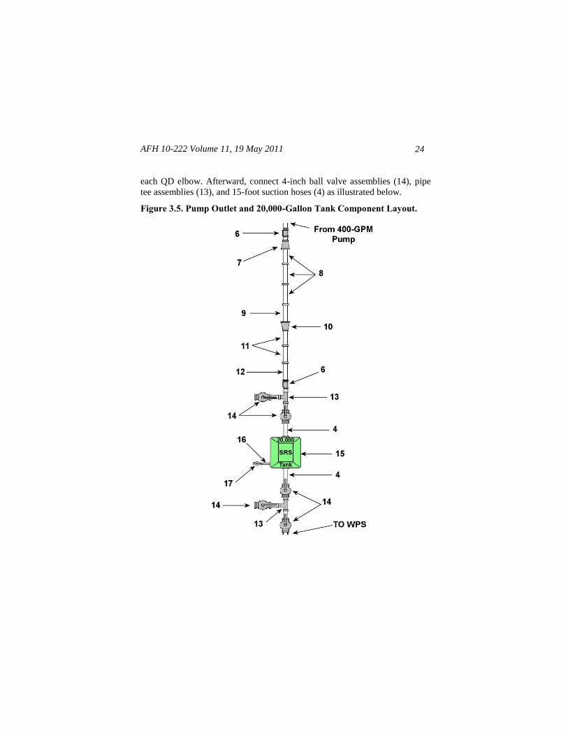
3.3.2.1. From the outlet side of the 400-GPM pump, connect a 4-inch x 15-
foot suction hose to the male QD fitting on the pump. Then attach, in order, a
4-inch swing check valve (6), and 6-inch x 4-inch reducer (7) to the hose.
3.3.2.2. Now, move to the WOA and complete the following actions. Position
the 20,000-gallon SRS tank (15) at the edge of the WOA as depicted in
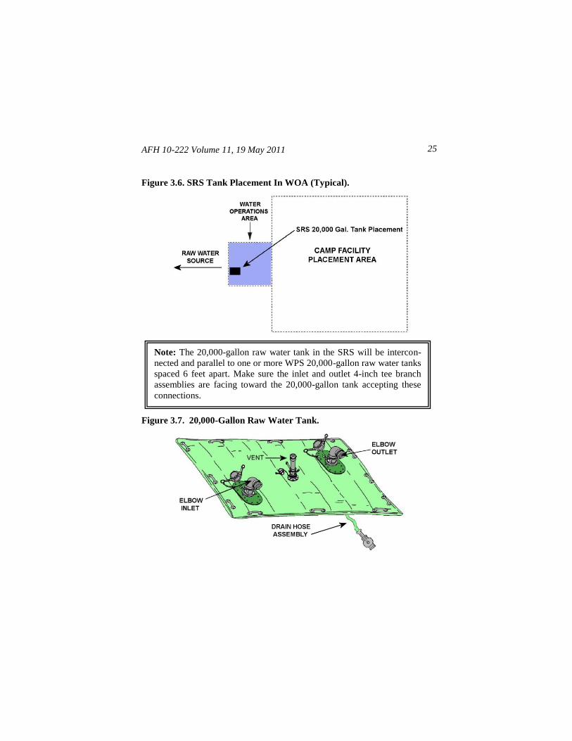
Figure 3.6. Then install the tank’s vent, drain hose and ball valve (16, 17),
and 4-inch inlet elbow (female-to-female) and outlet elbow (female-to-male)
onto the tank (Figure 3.7). Next, attach a 4-inch x 15-foot suction hose (4) to
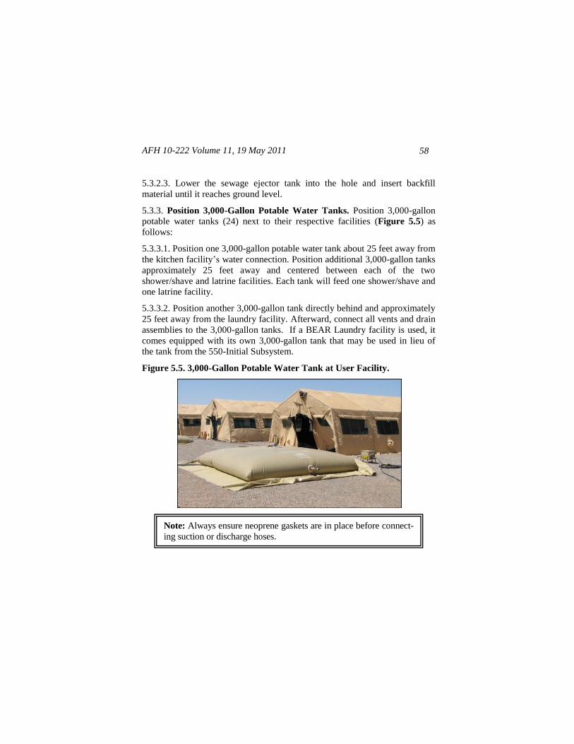
Note: Always ensure neoprene gaskets are in place before connect-
ing suction or discharge hoses.
AFH 10-222 Volume 11, 19 May 2011
24
each QD elbow. Afterward, connect 4-inch ball valve assemblies (14), pipe
tee assemblies (13), and 15-foot suction hoses (4) as illustrated below.
Figure 3.5. Pump Outlet and 20,000-Gallon Tank Component Layout.
AFH 10-222 Volume 11, 19 May 2011 25
Figure 3.6. SRS Tank Placement In WOA (Typical).
Figure 3.7. 20,000-Gallon Raw Water Tank.
Note: The 20,000-gallon raw water tank in the SRS will be intercon-
nected and parallel to one or more WPS 20,000-gallon raw water tanks
spaced 6 feet apart. Make sure the inlet and outlet 4-inch tee branch
assemblies are facing toward the 20,000-gallon tank accepting these
connections.
AFH 10-222 Volume 11, 19 May 2011
26
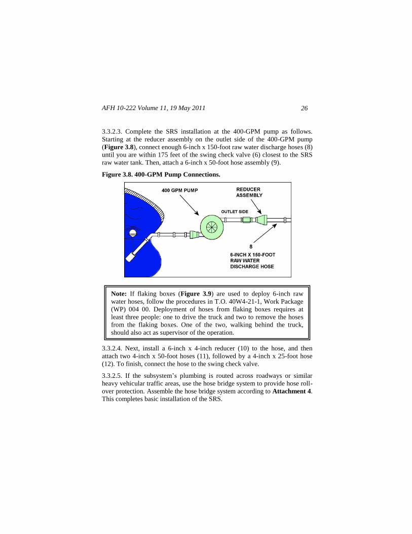
3.3.2.3. Complete the SRS installation at the 400-GPM pump as follows.
Starting at the reducer assembly on the outlet side of the 400-GPM pump
(Figure 3.8), connect enough 6-inch x 150-foot raw water discharge hoses (8)
until you are within 175 feet of the swing check valve (6) closest to the SRS
raw water tank. Then, attach a 6-inch x 50-foot hose assembly (9).
Figure 3.8. 400-GPM Pump Connections.
3.3.2.4. Next, install a 6-inch x 4-inch reducer (10) to the hose, and then
attach two 4-inch x 50-foot hoses (11), followed by a 4-inch x 25-foot hose
(12). To finish, connect the hose to the swing check valve.
3.3.2.5. If the subsystem’s plumbing is routed across roadways or similar
heavy vehicular traffic areas, use the hose bridge system to provide hose roll-
over protection. Assemble the hose bridge system according to Attachment 4.
This completes basic installation of the SRS.
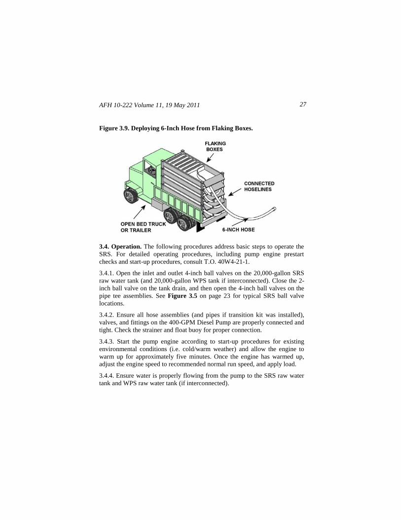
Note: If flaking boxes (Figure 3.9) are used to deploy 6-inch raw
water hoses, follow the procedures in T.O. 40W4-21-1, Work Package
(WP) 004 00. Deployment of hoses from flaking boxes requires at
least three people: one to drive the truck and two to remove the hoses
from the flaking boxes. One of the two, walking behind the truck,
should also act as supervisor of the operation.
AFH 10-222 Volume 11, 19 May 2011 27
Figure 3.9. Deploying 6-Inch Hose from Flaking Boxes.
3.4. Operation. The following procedures address basic steps to operate the
SRS. For detailed operating procedures, including pump engine prestart
checks and start-up procedures, consult T.O. 40W4-21-1.
3.4.1. Open the inlet and outlet 4-inch ball valves on the 20,000-gallon SRS
raw water tank (and 20,000-gallon WPS tank if interconnected). Close the 2-
inch ball valve on the tank drain, and then open the 4-inch ball valves on the
pipe tee assemblies. See Figure 3.5 on page 23 for typical SRS ball valve
locations.
3.4.2. Ensure all hose assemblies (and pipes if transition kit was installed),
valves, and fittings on the 400-GPM Diesel Pump are properly connected and
tight. Check the strainer and float buoy for proper connection.
3.4.3. Start the pump engine according to start-up procedures for existing
environmental conditions (i.e. cold/warm weather) and allow the engine to
warm up for approximately five minutes. Once the engine has warmed up,
adjust the engine speed to recommended normal run speed, and apply load.
3.4.4. Ensure water is properly flowing from the pump to the SRS raw water
tank and WPS raw water tank (if interconnected).
AFH 10-222 Volume 11, 19 May 2011
28
3.4.5. Once the pump is started and engaged, shut the pump down when the
raw water tanks are full; when service or maintenance is required; or when
the pump is likely to experience a dead head condition for more than a brief
period.
3.4.6. Be sure to periodically recheck all hoses, connections, pipes, valves,
fittings, and 20,000-gallon raw water tank(s) for leaks. Make needed repairs
and perform maintenance according to procedures in applicable technical
orders and manuals.
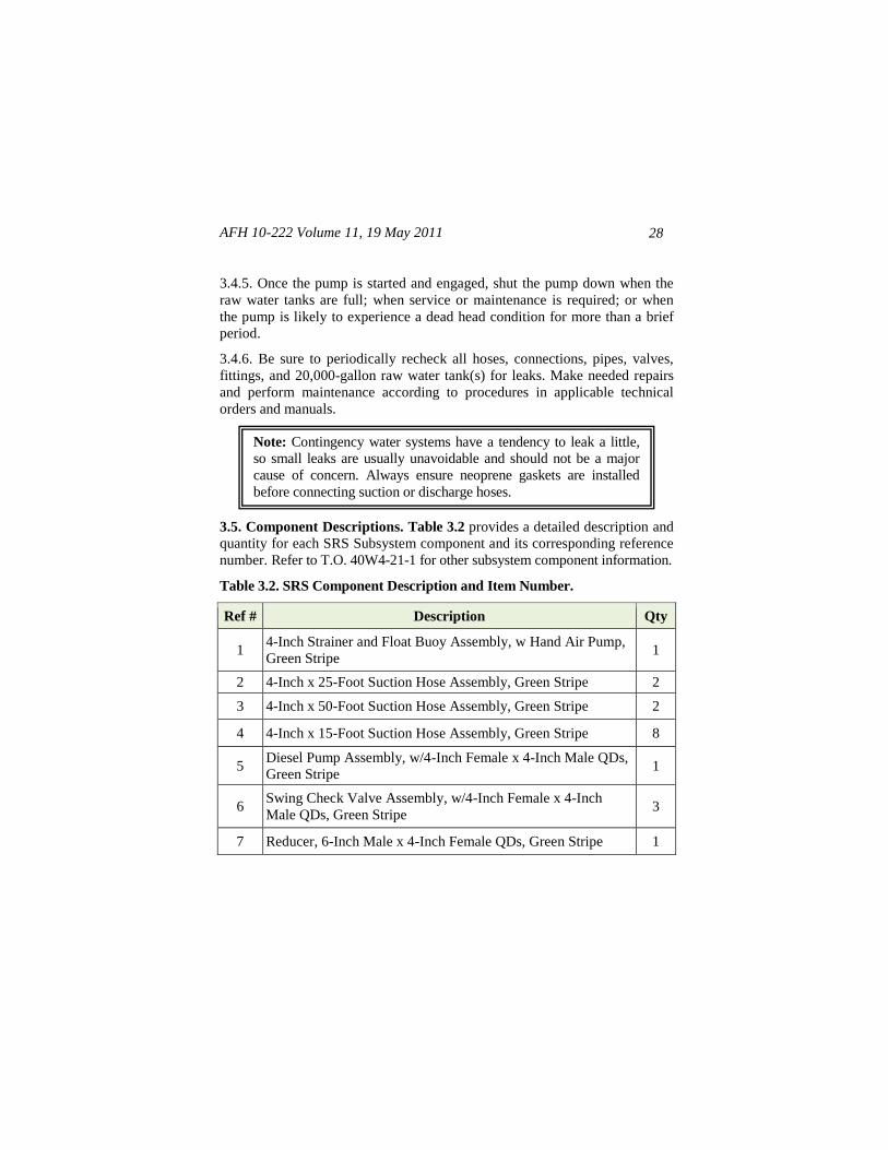
3.5. Component Descriptions. Table 3.2 provides a detailed description and
quantity for each SRS Subsystem component and its corresponding reference
number. Refer to T.O. 40W4-21-1 for other subsystem component information.
Table 3.2. SRS Component Description and Item Number.
Ref # Description Qty
1 4-Inch Strainer and Float Buoy Assembly, w Hand Air Pump,
Green Stripe 1
2 4-Inch x 25-Foot Suction Hose Assembly, Green Stripe 2
3 4-Inch x 50-Foot Suction Hose Assembly, Green Stripe 2
4 4-Inch x 15-Foot Suction Hose Assembly, Green Stripe 8
5 Diesel Pump Assembly, w/4-Inch Female x 4-Inch Male QDs,
Green Stripe 1
6 Swing Check Valve Assembly, w/4-Inch Female x 4-Inch
Male QDs, Green Stripe 3
7 Reducer, 6-Inch Male x 4-Inch Female QDs, Green Stripe 1
Note: Contingency water systems have a tendency to leak a little,
so small leaks are usually unavoidable and should not be a major
cause of concern. Always ensure neoprene gaskets are installed
before connecting suction or discharge hoses.
AFH 10-222 Volume 11, 19 May 2011 29
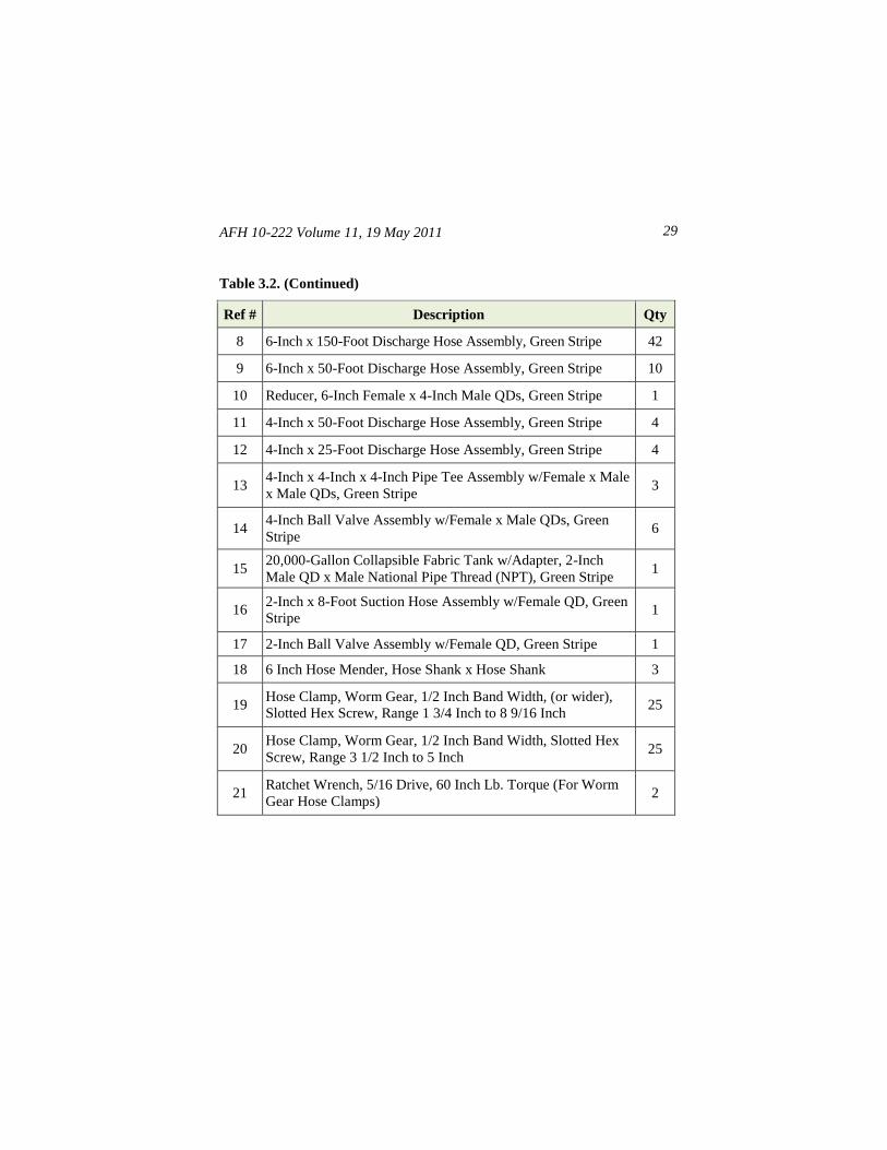
Table 3.2. (Continued)
Ref # Description Qty
8 6-Inch x 150-Foot Discharge Hose Assembly, Green Stripe 42
9 6-Inch x 50-Foot Discharge Hose Assembly, Green Stripe 10
10 Reducer, 6-Inch Female x 4-Inch Male QDs, Green Stripe 1
11 4-Inch x 50-Foot Discharge Hose Assembly, Green Stripe 4
12 4-Inch x 25-Foot Discharge Hose Assembly, Green Stripe 4
13 4-Inch x 4-Inch x 4-Inch Pipe Tee Assembly w/Female x Male
x Male QDs, Green Stripe 3
14 4-Inch Ball Valve Assembly w/Female x Male QDs, Green
Stripe 6
15 20,000-Gallon Collapsible Fabric Tank w/Adapter, 2-Inch
Male QD x Male National Pipe Thread (NPT), Green Stripe 1
16 2-Inch x 8-Foot Suction Hose Assembly w/Female QD, Green
Stripe 1
17 2-Inch Ball Valve Assembly w/Female QD, Green Stripe 1
18 6 Inch Hose Mender, Hose Shank x Hose Shank 3
19 Hose Clamp, Worm Gear, 1/2 Inch Band Width, (or wider),
Slotted Hex Screw, Range 1 3/4 Inch to 8 9/16 Inch 25
20 Hose Clamp, Worm Gear, 1/2 Inch Band Width, Slotted Hex
Screw, Range 3 1/2 Inch to 5 Inch 25
21 Ratchet Wrench, 5/16 Drive, 60 Inch Lb. Torque (For Worm
Gear Hose Clamps) 2
AFH 10-222 Volume 11, 19 May 2011
30
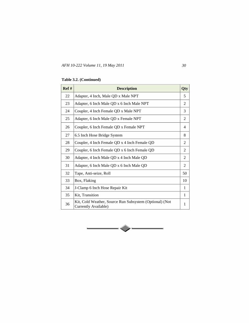
Table 3.2. (Continued)
Ref # Description Qty
22 Adapter, 4 Inch, Male QD x Male NPT 5
23 Adapter, 6 Inch Male QD x 6 Inch Male NPT 2
24 Coupler, 4 Inch Female QD x Male NPT 3
25 Adapter, 6 Inch Male QD x Female NPT 2
26 Coupler, 6 Inch Female QD x Female NPT 4
27 6.5 Inch Hose Bridge System 8
28 Coupler, 4 Inch Female QD x 4 Inch Female QD 2
29 Coupler, 6 Inch Female QD x 6 Inch Female QD 2
30 Adapter, 4 Inch Male QD x 4 Inch Male QD 2
31 Adapter, 6 Inch Male QD x 6 Inch Male QD 2
32 Tape, Anti-seize, Roll 50
33 Box, Flaking 10
34 J-Clamp 6 Inch Hose Repair Kit 1
35 Kit, Transition 1
36 Kit, Cold Weather, Source Run Subsystem (Optional) (Not
Currently Available) 1
AFH 10-222 Volume 11, 19 May 2011 31
Chapter 4
WATER PRODUCTION SUBSYSTEM
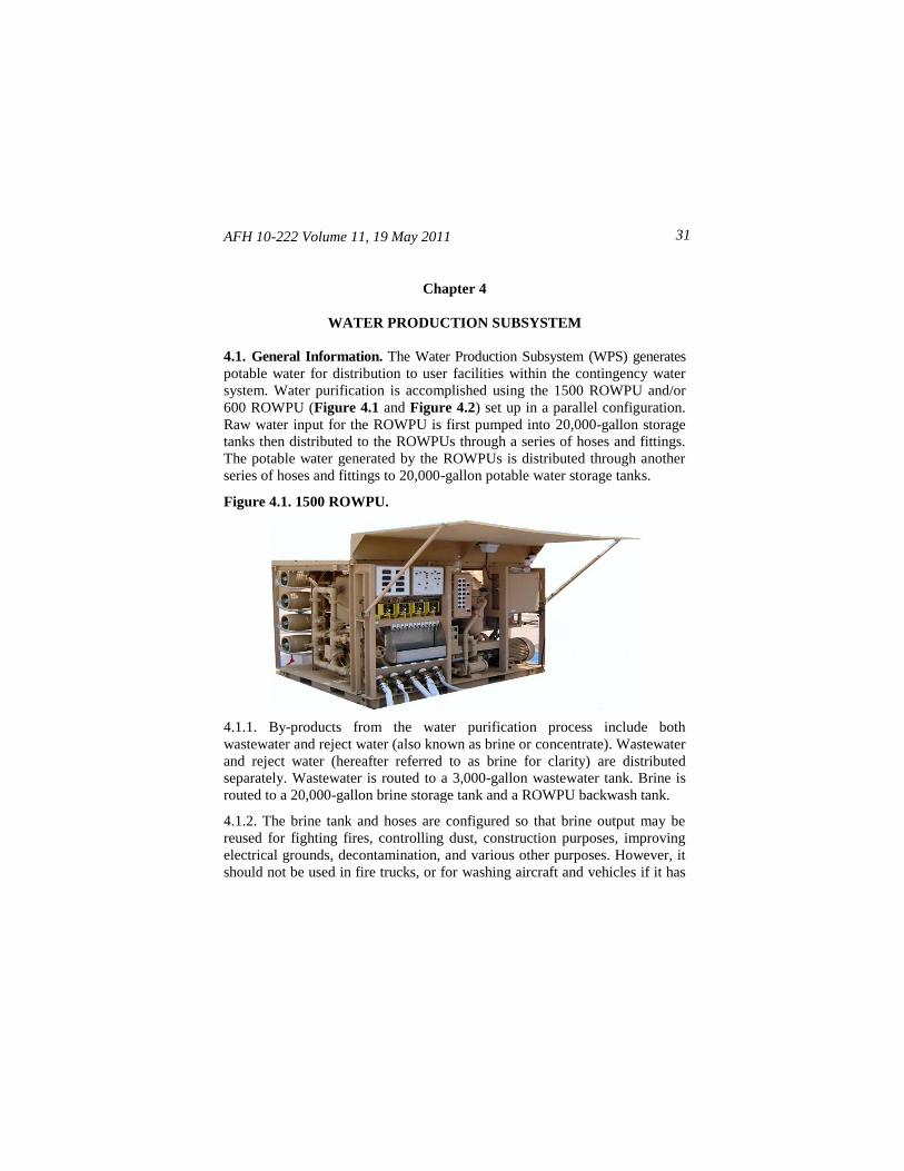
4.1. General Information. The Water Production Subsystem (WPS) generates
potable water for distribution to user facilities within the contingency water
system. Water purification is accomplished using the 1500 ROWPU and/or
600 ROWPU (Figure 4.1 and Figure 4.2) set up in a parallel configuration.
Raw water input for the ROWPU is first pumped into 20,000-gallon storage
tanks then distributed to the ROWPUs through a series of hoses and fittings.
The potable water generated by the ROWPUs is distributed through another
series of hoses and fittings to 20,000-gallon potable water storage tanks.
Figure 4.1. 1500 ROWPU.
4.1.1. By-products from the water purification process include both
wastewater and reject water (also known as brine or concentrate). Wastewater
and reject water (hereafter referred to as brine for clarity) are distributed
separately. Wastewater is routed to a 3,000-gallon wastewater tank. Brine is
routed to a 20,000-gallon brine storage tank and a ROWPU backwash tank.
4.1.2. The brine tank and hoses are configured so that brine output may be
reused for fighting fires, controlling dust, construction purposes, improving
electrical grounds, decontamination, and various other purposes. However, it
should not be used in fire trucks, or for washing aircraft and vehicles if it has
AFH 10-222 Volume 11, 19 May 2011
32
a high salt content. If brine is not reused, it, along with ROWPU wastewater
is distributed by a 35-GPM electric pump (or backup 125-GPM diesel pump)
to waste disposal.
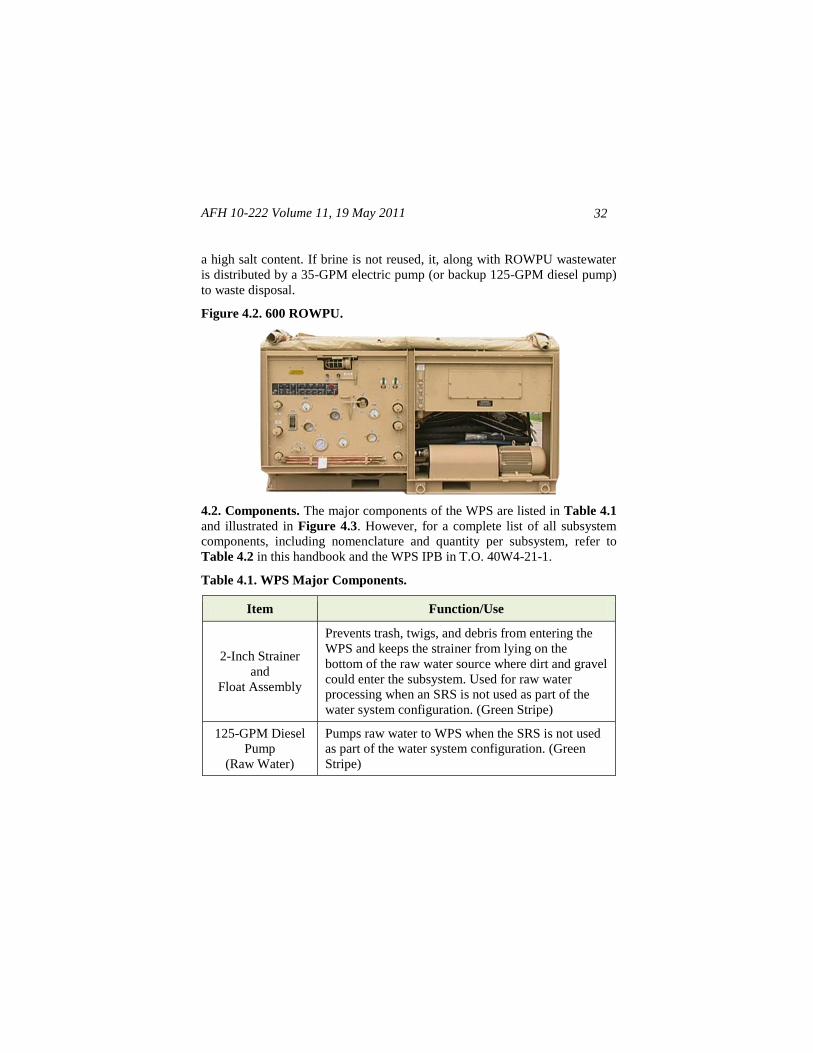
Figure 4.2. 600 ROWPU.
4.2. Components. The major components of the WPS are listed in Table 4.1
and illustrated in Figure 4.3. However, for a complete list of all subsystem
components, including nomenclature and quantity per subsystem, refer to
Table 4.2 in this handbook and the WPS IPB in T.O. 40W4-21-1.
Table 4.1. WPS Major Components.
Item Function/Use
2-Inch Strainer
and
Float Assembly
Prevents trash, twigs, and debris from entering the
WPS and keeps the strainer from lying on the
bottom of the raw water source where dirt and gravel
could enter the subsystem. Used for raw water
processing when an SRS is not used as part of the
water system configuration. (Green Stripe)
125-GPM Diesel
Pump
(Raw Water)
Pumps raw water to WPS when the SRS is not used
as part of the water system configuration. (Green
Stripe)
AFH 10-222 Volume 11, 19 May 2011 33
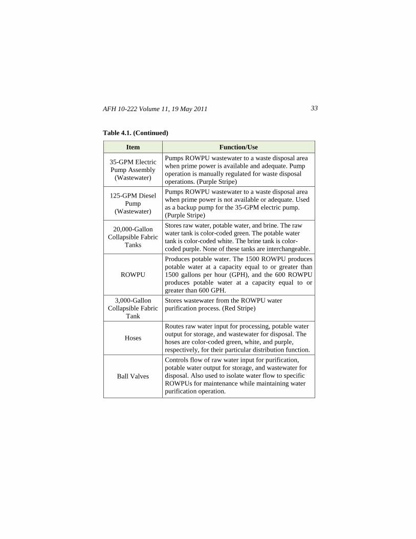
Table 4.1. (Continued)
Item Function/Use
35-GPM Electric
Pump Assembly
(Wastewater)
Pumps ROWPU wastewater to a waste disposal area
when prime power is available and adequate. Pump
operation is manually regulated for waste disposal
operations. (Purple Stripe)
125-GPM Diesel
Pump
(Wastewater)
Pumps ROWPU wastewater to a waste disposal area
when prime power is not available or adequate. Used
as a backup pump for the 35-GPM electric pump.
(Purple Stripe)
20,000-Gallon
Collapsible Fabric
Tanks
Stores raw water, potable water, and brine. The raw
water tank is color-coded green. The potable water
tank is color-coded white. The brine tank is color-
coded purple. None of these tanks are interchangeable.
ROWPU
Produces potable water. The 1500 ROWPU produces
potable water at a capacity equal to or greater than
1500 gallons per hour (GPH), and the 600 ROWPU
produces potable water at a capacity equal to or
greater than 600 GPH.
3,000-Gallon
Collapsible Fabric
Tank
Stores wastewater from the ROWPU water
purification process. (Red Stripe)
Hoses
Routes raw water input for processing, potable water
output for storage, and wastewater for disposal. The
hoses are color-coded green, white, and purple,
respectively, for their particular distribution function.
Ball Valves
Controls flow of raw water input for purification,
potable water output for storage, and wastewater for
disposal. Also used to isolate water flow to specific
ROWPUs for maintenance while maintaining water
purification operation.
AFH 10-222 Volume 11, 19 May 2011
34
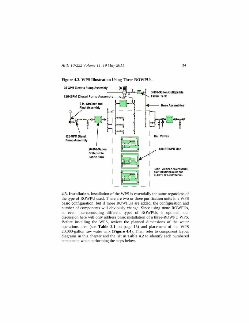
Figure 4.3. WPS Illustration Using Three ROWPUs.
4.3. Installation. Installation of the WPS is essentially the same regardless of
the type of ROWPU used. There are two or three purification units in a WPS
basic configuration, but if more ROWPUs are added, the configuration and
number of components will obviously change. Since using more ROWPUs,
or even interconnecting different types of ROWPUs is optional, our
discussion here will only address basic installation of a three-ROWPU WPS.
Before installing the WPS, review the planned dimensions of the water
operations area (see Table 2.1 on page 15) and placement of the WPS
20,000-gallon raw water tank (Figure 4.4). Then, refer to component layout
diagrams in this chapter and the list in Table 4.2 to identify each numbered
component when performing the steps below.
AFH 10-222 Volume 11, 19 May 2011 35
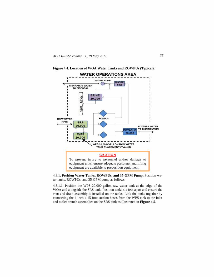
Figure 4.4. Location of WOA Water Tanks and ROWPUs (Typical).
4.3.1. Position Water Tanks, ROWPUs, and 35-GPM Pump. Position wa-
ter tanks, ROWPUs, and 35-GPM pump as follows:
4.3.1.1. Position the WPS 20,000-gallon raw water tank at the edge of the
WOA and alongside the SRS tank. Position tanks six feet apart and ensure the
vent and drain assembly is installed on the tanks. Link the tanks together by
connecting the 4-inch x 15-foot suction hoses from the WPS tank to the inlet
and outlet branch assemblies on the SRS tank as illustrated in Figure 4.5.
CAUTION
To prevent injury to personnel and/or damage to
equipment units, ensure adequate personnel and lifting
equipment are available to preposition equipment.
AFH 10-222 Volume 11, 19 May 2011
36
4.3.1.2. Before positioning ROWPUs verify that a 120-Volt Alternating
Current (VAC), 1-phase, 60-Hertz (Hz) and a 208-VAC, 3-phase, 60-Hz
power source is available. Then, position ROWPUs approximately 20 feet
from the WPS raw water tank and make sure to provide 10 feet of clearance
between each water purification unit.
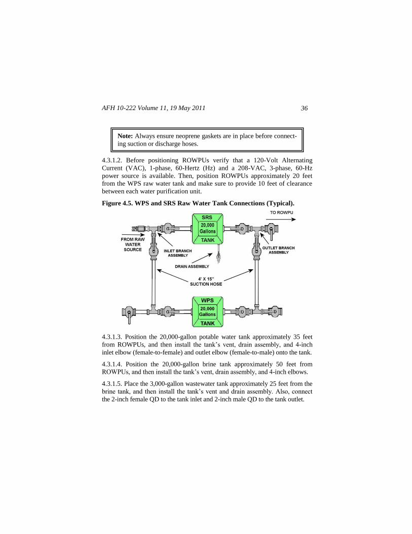
Figure 4.5. WPS and SRS Raw Water Tank Connections (Typical).
4.3.1.3. Position the 20,000-gallon potable water tank approximately 35 feet
from ROWPUs, and then install the tank’s vent, drain assembly, and 4-inch
inlet elbow (female-to-female) and outlet elbow (female-to-male) onto the tank.
4.3.1.4. Position the 20,000-gallon brine tank approximately 50 feet from
ROWPUs, and then install the tank’s vent, drain assembly, and 4-inch elbows.
4.3.1.5. Place the 3,000-gallon wastewater tank approximately 25 feet from the
brine tank, and then install the tank’s vent and drain assembly. Also, connect
the 2-inch female QD to the tank inlet and 2-inch male QD to the tank outlet.
Note: Always ensure neoprene gaskets are in place before connect-
ing suction or discharge hoses.
AFH 10-222 Volume 11, 19 May 2011 37
4.3.1.6. Before positioning the 35-GPM electric pump, verify that 208-VAC,
1-phase, 60-Hz power is available. Then, place the electric pump
approximately 25 feet from the 3,000-gallon wastewater tank. If power is not
available, use the backup 125-GPM diesel pump.
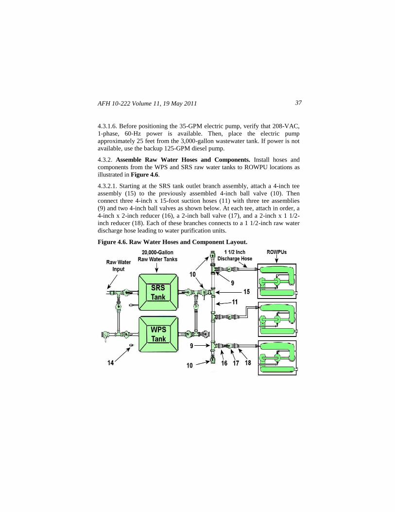
4.3.2. Assemble Raw Water Hoses and Components. Install hoses and
components from the WPS and SRS raw water tanks to ROWPU locations as
illustrated in Figure 4.6.
4.3.2.1. Starting at the SRS tank outlet branch assembly, attach a 4-inch tee
assembly (15) to the previously assembled 4-inch ball valve (10). Then
connect three 4-inch x 15-foot suction hoses (11) with three tee assemblies
(9) and two 4-inch ball valves as shown below. At each tee, attach in order, a
4-inch x 2-inch reducer (16), a 2-inch ball valve (17), and a 2-inch x 1 1/2-
inch reducer (18). Each of these branches connects to a 1 1/2-inch raw water
discharge hose leading to water purification units.
Figure 4.6. Raw Water Hoses and Component Layout.
AFH 10-222 Volume 11, 19 May 2011
38
4.3.2.2. After connecting the 1 1/2-inch reducer to the ROWPU hoses, ensure
the ball valves at the inlet and outlet sides of the WPS raw water tank are open
and the ball valves on the three branch outlets are closed. Then confirm the ball
valves (14) are closed on both WPS and SRS raw water tank drain hoses. After
that, ensure the ball valves on the valve inlets to the ROWPUs are also closed.
Keep this configuration until the subsystem is ready to begin water production
operations.
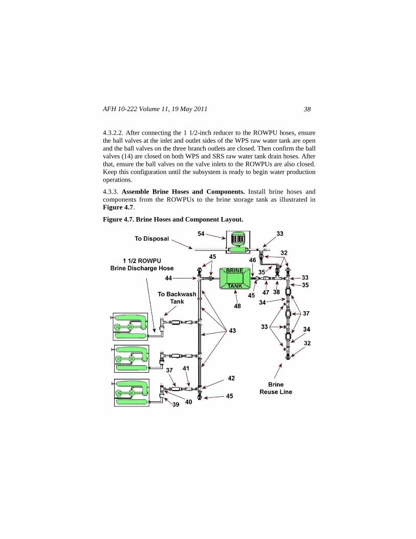
4.3.3. Assemble Brine Hoses and Components. Install brine hoses and
components from the ROWPUs to the brine storage tank as illustrated in
Figure 4.7.
Figure 4.7. Brine Hoses and Component Layout.
AFH 10-222 Volume 11, 19 May 2011 39
4.3.3.1. Starting at the 1 1/2-inch brine discharge hoses from the ROWPUs,
attach in order, a 2-inch x 1 1/2-inch reducer (39), a 2-inch tee (40), a check
valve (37), a 4-inch x 2-inch reducer (41), and a 4-inch tee (42) on each
output hose.
4.3.3.2. Next, connect the 4-inch x 25-foot brine hoses (43) to the tee
assemblies and position the hoses so they head towards the brine storage tank
(48).
4.3.3.3. Attach a 4-inch tee (44) on the end of the brine hose facing the brine
storage tank. Then, connect a ball valve (45) to the open end of each tee
assembly.
4.3.3.4. Next, connect one end of a 4-inch x 15-foot brine suction hose (46) to
the ball valve facing the brine tank. Attach the other end of the hose to the
tank inlet.
4.3.3.5. On the tank outlet, attach another 4-inch x 15-foot brine hose,
followed by a 4-inch ball valve (45), 4-inch x 2-inch reducer (47), and 2-inch
tee assembly (38).
4.3.3.6. For brine disposal, start at the 2-inch tee (38) and attach a 2-inch ball
valve (32) followed by a 2-inch x 50-foot discharge hose (35). Next, attach
another 2-inch ball valve and 2-inch tee (33). Afterward, connect the tee to
the 35-GPM wastewater pump (54) for disposal.
4.3.3.7. For brine reuse, start at the 2-inch tee (38) and attach another 2-inch
tee (33) followed by a 2-inch ball valve on one end (32) and a 2-inch x 50-
foot discharge hose (35) on the other. Next, attach a 2-inch check valve (37)
followed by three 2-inch x 25-foot discharge hoses (34), with 2-inch check
valves and tees installed. At the last tee on the end of the discharge hose,
attach another 2-inch ball valve. From this valve, brine can be drawn and
reused for washing vehicles, decontamination, firefighting, wetting dusty
roads, and other various user purposes.
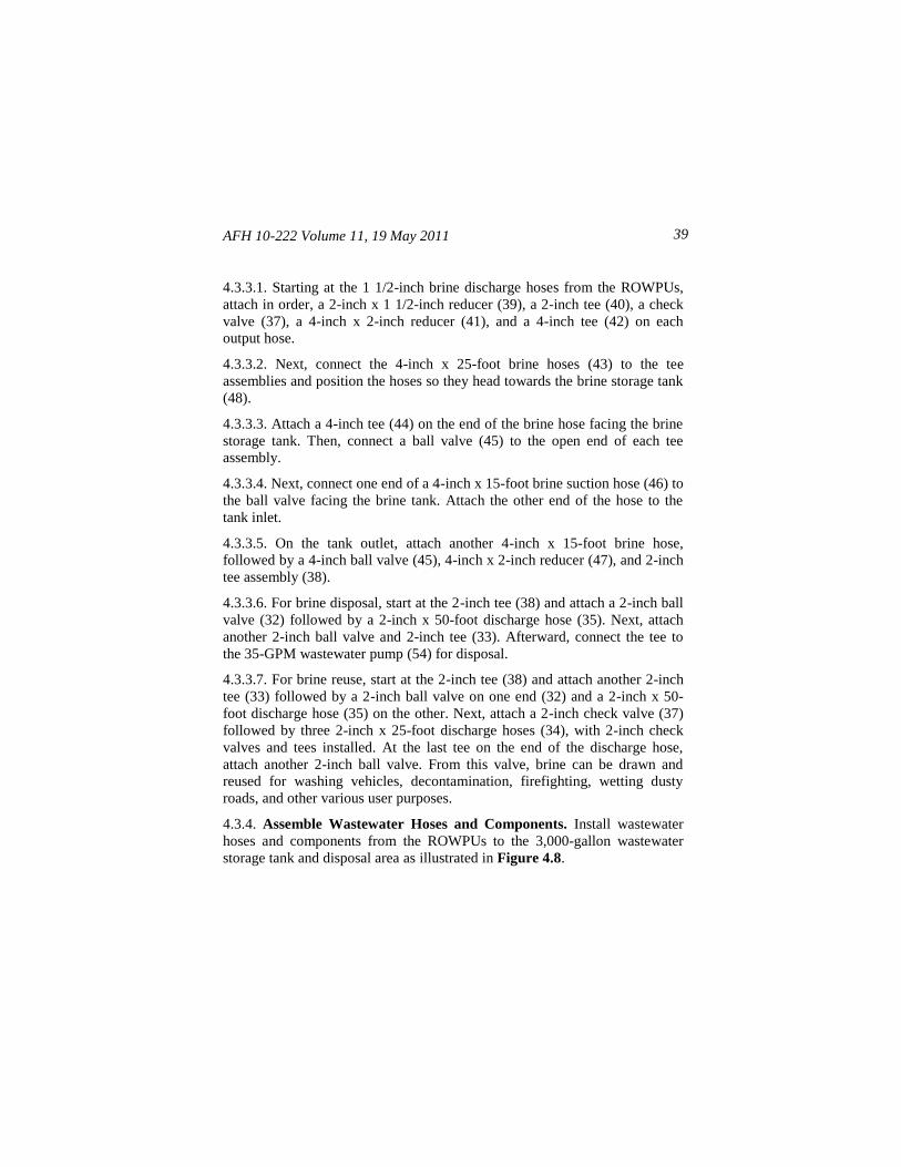
4.3.4. Assemble Wastewater Hoses and Components. Install wastewater
hoses and components from the ROWPUs to the 3,000-gallon wastewater
storage tank and disposal area as illustrated in Figure 4.8.
AFH 10-222 Volume 11, 19 May 2011
40
4.3.4.1. Starting at the ROWPUs’ 2-inch wastewater output hoses, attach a 2-
inch tee (33) to each hose end. Then, connect two 2-inch x 25-foot wastewater
discharge hoses (34) as shown below. Attach a 2-inch ball valve (32) on the
open end of the first tee. On the open end of the third tee assembly, connect
enough 2-inch x 25-foot suction hoses (36) to reach the wastewater tank.
Figure 4.8. Wastewater Hoses and Component Layout.
Note: Always ensure neoprene gaskets are in place before connect-
ing suction or discharge hoses.
AFH 10-222 Volume 11, 19 May 2011 41
4.3.4.2. At the end of the suction hose, connect another 2-inch tee (38),
followed by 2-inch ball valves (32) on the open ends of the tee. Afterward,
attach the ball valve nearest the tank to the wastewater tank (51) inlet.
4.3.4.3. On the wastewater tank outlet, attach a 2-inch ball valve followed by a
2-inch tee assembly and a 2-inch x 50-foot wastewater discharge hose (35).
Afterward, attach another 2-inch ball valve on the open end of the tee. Then,
attach the discharge hose to the tee (33) that is closest to the 35-GPM pump.
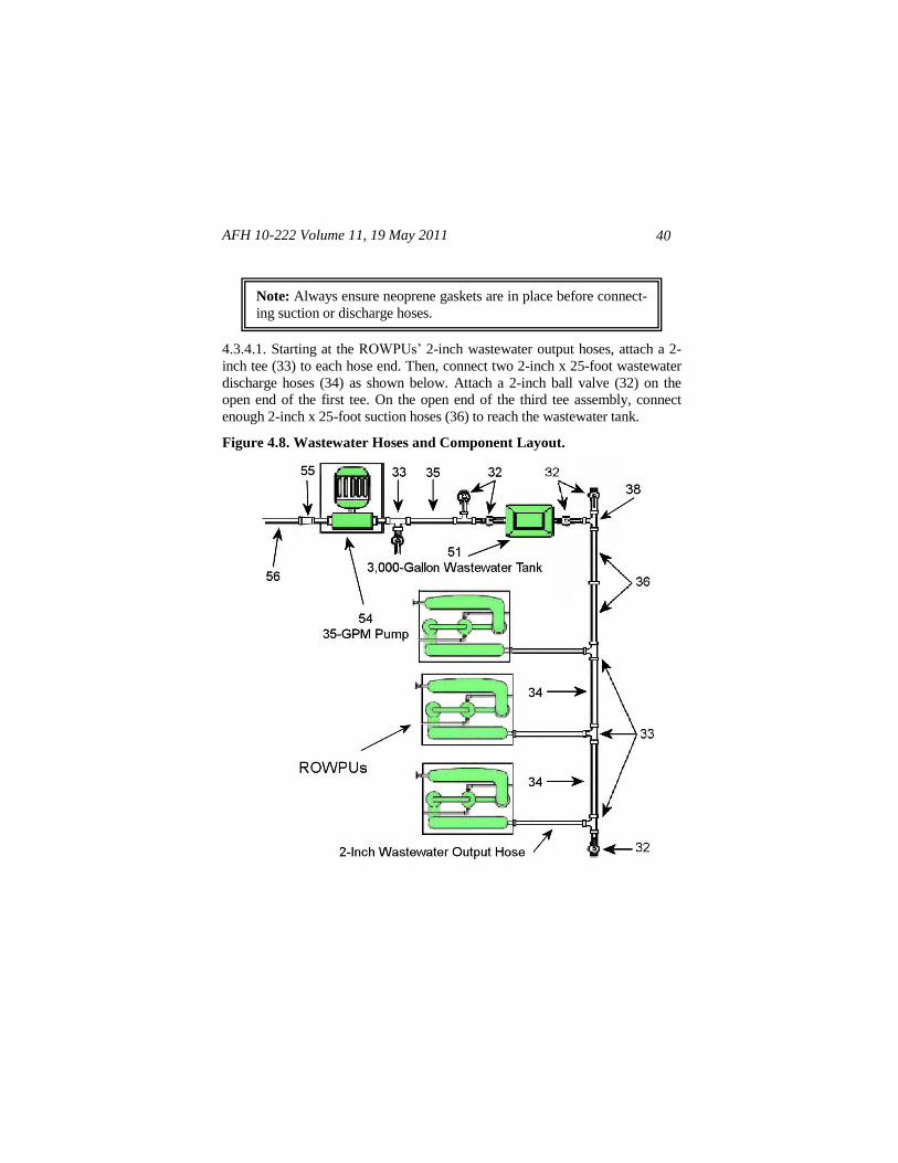
4.3.5. Assemble Potable Water Hoses and Components. Install potable
water hoses and components from the ROWPUs to the potable water storage
tank as illustrated in Figure 4.9.
Figure 4.9. Potable Water Hoses and Component Layout.
4.3.5.1. Starting at the 1 1/2-inch potable water output hoses from the ROWPUs,
attach a 2-inch x 1 1/2-inch reducer (20) and 2-inch check valve (21) to each
hose. Afterward, attach a 2-inch x 25-foot suction hose (22) to the first and
third (outside) lines and install the 2-inch tees (23, 24) as shown.
4.3.5.2. At the 2-inch tee (24), install a 4-inch x 2-inch reducer (25) followed
by a 4-inch tee (26) on the end of the reducer. Afterward, attach a 4-inch ball
valve (27) to the free ends of the tee.
AFH 10-222 Volume 11, 19 May 2011
42
4.3.5.3. From the 4-inch ball valves, attach three 4-inch x 15-foot suction
hoses (28): attach a line of two hoses to the ball valve that points towards the
potable water tank (29), and attach the other hose to the ball valve that points
away from the potable water tank. Afterward, connect the suction hose to the
potable water tank inlet.
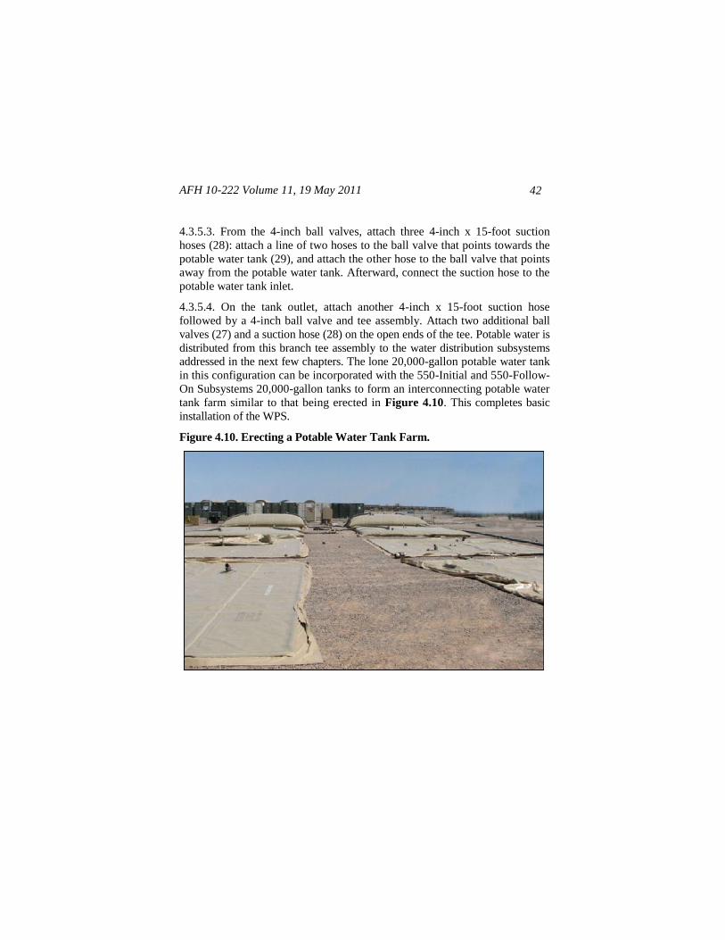
4.3.5.4. On the tank outlet, attach another 4-inch x 15-foot suction hose
followed by a 4-inch ball valve and tee assembly. Attach two additional ball
valves (27) and a suction hose (28) on the open ends of the tee. Potable water is
distributed from this branch tee assembly to the water distribution subsystems
addressed in the next few chapters. The lone 20,000-gallon potable water tank
in this configuration can be incorporated with the 550-Initial and 550-Follow-
On Subsystems 20,000-gallon tanks to form an interconnecting potable water
tank farm similar to that being erected in Figure 4.10. This completes basic
installation of the WPS.
Figure 4.10. Erecting a Potable Water Tank Farm.
AFH 10-222 Volume 11, 19 May 2011 43
4.4. Operation. The following procedures address basic steps to operate the
WPS after installation. If necessary, refer back to the basic layout diagrams
presented throughout this chapter for part identification when performing
these steps.
4.4.1. Open the inlet and outlet 4-inch ball valves on the 20,000-gallon WPS
raw water tank (and 20,000-gallon SRS tank if interconnected). Close the 2-
inch ball valve on the tank drain(s), and then open the 4-inch ball valves on
the branch tees. Ensure proper connection and tightness of all hose
assemblies, valves, and fittings for 20,000-gallon raw water tanks.
4.4.2. Repeat this procedure on the 20,000-gallon potable water tank. Also,
verify that all potable water fittings, valves, and hoses are color-coded white.
4.4.3. Open the 2-inch ball valve on the 3,000-gallon wastewater tank inlet
and close the 2-inch ball valve on the end of the inlet branch tee. Ensure all
hose assemblies, valves, and fittings associated with the wastewater tank is
properly connected and color-coded purple.
4.4.3.1. Close the 2-inch ball valves on the wastewater tank outlet, the branch
tee, and the tee leading to the brine system.
4.4.3.2. Ensure all hoses, valves, and fittings, associated with the wastewater
tank discharge system, are properly connected, and color-coded purple.
4.4.4. Check the 35-GPM Electric Pump for adequate power, and verify that
all fittings and connections are tight and color-coded purple. If adequate
power is not available, use the 125-GPM Diesel Pump.
Note: For ROWPU operating procedures, consult T.O. 40W4-21-1,
AFH 10-222, Volume 9, Guide to Reverse Osmosis Water Purifica-
tion Unit Installation and Operation, and the applicable technical
orders for the ROWPU (T.O. 40W4-13-41, Operation Manual—
Water Purification, Reverse Osmosis, 600GPH Skid Mounted
ROWPU Model WPES-20, and T.O. 40W4-20-1, Operation and
Maintenance Instruction With IPB – 1500 Reverse Osmosis Water
Purification Unit (ROWPU).
AFH 10-222 Volume 11, 19 May 2011
44
4.4.5. Open the 4-inch ball valve on the 20,000-gallon brine tank and close
the 4-inch ball valves on the branch tees.
4.4.5.1. Close the 2-inch ball valves on the branch tees and 2-inch ball valve
on the tank drain.
4.4.5.2. Ensure all hoses, valves, and fittings, associated with the outlet of the
20,000-gallon brine tank, are properly connected, and color-coded purple.
4.4.6. Recheck all hose assemblies, valves, fittings, and the 20,000-gallon raw
water tank for leaks and repair as required
4.4.7. Start up ROWPU units according to procedures in the applicable
ROWPU technical order (i.e. T.O. 40W4-13-41 for the WPES-20 and T.O.
40W4-20-1 for the 1500), and verify the flow of potable water into the
20,000-gallon potable water tank.
4.4.8. Recheck all hose assemblies, valves, fittings associated with the
potable water system, and the 20,000-gallon potable water tank for leaks and
repair as required. Repeat these procedures for the brine and wastewater
systems and tanks.
4.4.9. Recheck all hose assemblies, valves, and fittings connected to the 35-GPM
Electric Pump for leaks and repair as required.
4.4.10. When the 3,000-gallon wastewater tank reaches its capacity, turn ON
the 35-GPM pump to discharge wastewater from the tank. Turn the pump
OFF when the 3,000-gallon tank is empty. Restart as required to dispose of
wastewater. If the 125-GPM Diesel Pump was used in lieu of the 35-GPM
pump, refer to T.O. 40W4-21-1 for startup and shutdown procedures.
Note: Wastewater disposal should be accomplished according to
MAJCOM directives or local policies.
Note: Contingency water systems have a tendency to leak a little,
so small leaks are usually unavoidable and should not be a major
cause of concern. Always ensure neoprene gaskets are installed
before connecting suction or discharge hoses.
AFH 10-222 Volume 11, 19 May 2011 45
4.4.11. If potable water production exceeds demand and 20,000-gallon
potable water storage tanks are full, stop water production by shutting down
ROWPU operations according to the applicable ROWPU technical order and
terminate operation of the Source Run Subsystem’s 400-GPM Diesel Pump
according to instructions in the Commercial Operator's Manual for Power
Tech 4.5/6.8 L Tier 2 OEM Diesel Engines. See Attachment 1 for specific
references.
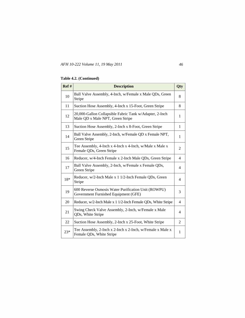
4.5. WPS Component Descriptions. Table 4.2 lists detailed descriptions and
quantities for WPS Subsystem components and their corresponding reference
number. Refer to T.O. 40W4-21-1 for other subsystem component
information.
Table 4.2. WPS Component Description and Item Number.
Ref # Description Qty
1 Strainer And Float Buoy Assembly, 2-Inch, w/Pump, Air,
Hand, Green Stripe 1
2 Suction Hose Assembly, 2-Inch x 25-Foot, Green Stripe 4
3 Pump Assembly, 2-Inch Diesel, w/Female x Male QDs,
Green Stripe 1
4 Reducer, w/3-Inch Male x 2-Inch Female QDs, Green Stripe 1
5 Discharge Hose Assembly, 3-Inch x 100-Foot, Green Stripe 5
6 Swing Check Valve Assembly, 3-Inch, PVC, w/Female x
Male QDs, Green Stripe 1
7 Reducer, w/4-Inch Male x 3-Inch Female, Green Stripe 2
8 Suction Hose Assembly, 4-Inch x 50-Foot, Green Stripe 2
9 Tee Assembly, 4-Inch x 4-Inch x 4-Inch, w/Female x Male x
Male QDs, Green Stripe 7
AFH 10-222 Volume 11, 19 May 2011
46
Table 4.2. (Continued)
Ref # Description Qty
10 Ball Valve Assembly, 4-Inch, w/Female x Male QDs, Green
Stripe 8
11 Suction Hose Assembly, 4-Inch x 15-Foot, Green Stripe 8
12 20,000-Gallon Collapsible Fabric Tank w/Adapter, 2-Inch
Male QD x Male NPT, Green Stripe 1
13 Suction Hose Assembly, 2-Inch x 8-Foot, Green Stripe 1
14 Ball Valve Assembly, 2-Inch, w/Female QD x Female NPT,
Green Stripe 1
15 Tee Assembly, 4-Inch x 4-Inch x 4-Inch, w/Male x Male x
Female QDs, Green Stripe 2
16 Reducer, w/4-Inch Female x 2-Inch Male QDs, Green Stripe 4
17 Ball Valve Assembly, 2-Inch, w/Female x Female QDs,
Green Stripe 4
18* Reducer, w/2-Inch Male x 1 1/2-Inch Female QDs, Green
Stripe 4
19 600 Reverse Osmosis Water Purification Unit (ROWPU)
Government Furnished Equipment (GFE) 3
20 Reducer, w/2-Inch Male x 1 1/2-Inch Female QDs, White Stripe 4
21 Swing Check Valve Assembly, 2-Inch, w/Female x Male
QDs, White Stripe 4
22 Suction Hose Assembly, 2-Inch x 25-Foot, White Stripe 2
23* Tee Assembly, 2-Inch x 2-Inch x 2-Inch, w/Female x Male x
Female QDs, White Stripe 1
AFH 10-222 Volume 11, 19 May 2011 47
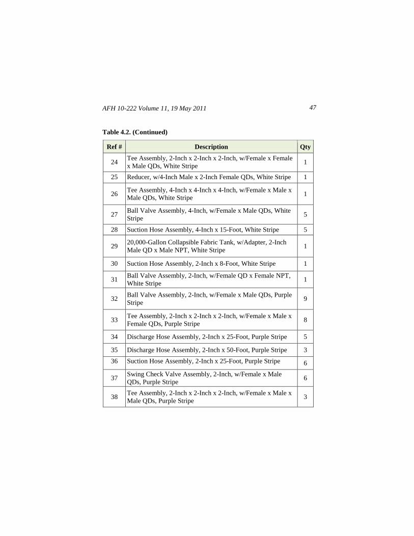
Table 4.2. (Continued)
Ref # Description Qty
24 Tee Assembly, 2-Inch x 2-Inch x 2-Inch, w/Female x Female
x Male QDs, White Stripe 1
25 Reducer, w/4-Inch Male x 2-Inch Female QDs, White Stripe 1
26 Tee Assembly, 4-Inch x 4-Inch x 4-Inch, w/Female x Male x
Male QDs, White Stripe 1
27 Ball Valve Assembly, 4-Inch, w/Female x Male QDs, White
Stripe 5
28 Suction Hose Assembly, 4-Inch x 15-Foot, White Stripe 5
29 20,000-Gallon Collapsible Fabric Tank, w/Adapter, 2-Inch
Male QD x Male NPT, White Stripe 1
30 Suction Hose Assembly, 2-Inch x 8-Foot, White Stripe 1
31 Ball Valve Assembly, 2-Inch, w/Female QD x Female NPT,
White Stripe 1
32 Ball Valve Assembly, 2-Inch, w/Female x Male QDs, Purple
Stripe 9
33 Tee Assembly, 2-Inch x 2-Inch x 2-Inch, w/Female x Male x
Female QDs, Purple Stripe 8
34 Discharge Hose Assembly, 2-Inch x 25-Foot, Purple Stripe 5
35 Discharge Hose Assembly, 2-Inch x 50-Foot, Purple Stripe 3
36 Suction Hose Assembly, 2-Inch x 25-Foot, Purple Stripe 6
37 Swing Check Valve Assembly, 2-Inch, w/Female x Male
QDs, Purple Stripe 6
38 Tee Assembly, 2-Inch x 2-Inch x 2-Inch, w/Female x Male x
Male QDs, Purple Stripe 3
AFH 10-222 Volume 11, 19 May 2011
48
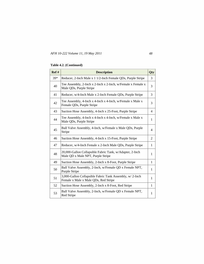
Table 4.2. (Continued)
Ref # Description Qty
39* Reducer, 2-Inch Male x 1 1/2-Inch Female QDs, Purple Stripe 3
40 Tee Assembly, 2-Inch x 2-Inch x 2-Inch, w/Female x Female x
Male QDs, Purple Stripe 3
41 Reducer, w/4-Inch Male x 2-Inch Female QDs, Purple Stripe 3
42 Tee Assembly, 4-Inch x 4-Inch x 4-Inch, w/Female x Male x
Female QDs, Purple Stripe 3
43 Suction Hose Assembly, 4-Inch x 25-Foot, Purple Stripe 4
44 Tee Assembly, 4-Inch x 4-Inch x 4-Inch, w/Female x Male x
Male QDs, Purple Stripe 1
45 Ball Valve Assembly, 4-Inch, w/Female x Male QDs, Purple
Stripe 4
46 Suction Hose Assembly, 4-Inch x 15-Foot, Purple Stripe 2
47 Reducer, w/4-Inch Female x 2-Inch Male QDs, Purple Stripe 1
48 20,000-Gallon Collapsible Fabric Tank, w/Adapter, 2-Inch
Male QD x Male NPT, Purple Stripe 1
49 Suction Hose Assembly, 2-Inch x 8-Foot, Purple Stripe 1
50 Ball Valve Assembly, 2-Inch, w/Female QD x Female NPT,
Purple Stripe 1
51 3,000-Gallon Collapsible Fabric Tank Assembly, w/ 2-Inch
Female x Male x Male QDs, Red Stripe 1
52 Suction Hose Assembly, 2-Inch x 8-Foot, Red Stripe 1
53 Ball Valve Assembly, 2-Inch, w/Female QD x Female NPT,
Red Stripe 1
AFH 10-222 Volume 11, 19 May 2011 49
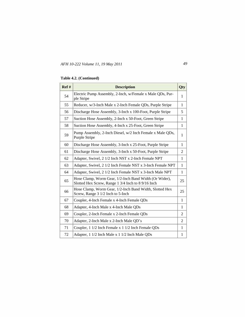
Table 4.2. (Continued)
Ref # Description Qty
54 Electric Pump Assembly, 2-Inch, w/Female x Male QDs, Pur-
ple Stripe 1
55 Reducer, w/3-Inch Male x 2-Inch Female QDs, Purple Stripe 1
56 Discharge Hose Assembly, 3-Inch x 100-Foot, Purple Stripe 5
57 Suction Hose Assembly, 2-Inch x 50-Foot, Green Stripe 1
58 Suction Hose Assembly, 4-Inch x 25-Foot, Green Stripe 1
59 Pump Assembly, 2-Inch Diesel, w/2 Inch Female x Male QDs,
Purple Stripe 1
60 Discharge Hose Assembly, 3-Inch x 25-Foot, Purple Stripe 1
61 Discharge Hose Assembly, 3-Inch x 50-Foot, Purple Stripe 2
62 Adapter, Swivel, 2 1/2 Inch NST x 2-Inch Female NPT 1
63 Adapter, Swivel, 2 1/2 Inch Female NST x 3-Inch Female NPT 1
64 Adapter, Swivel, 2 1/2 Inch Female NST x 3-Inch Male NPT 1
65 Hose Clamp, Worm Gear, 1/2-Inch Band Width (Or Wider),
Slotted Hex Screw, Range 1 3/4 Inch to 8 9/16 Inch 25
66 Hose Clamp, Worm Gear, 1/2-Inch Band Width, Slotted Hex
Screw, Range 3 1/2 Inch to 5-Inch 25
67 Coupler, 4-Inch Female x 4-Inch Female QDs 1
68 Adapter, 4-Inch Male x 4-Inch Male QDs 1
69 Coupler, 2-Inch Female x 2-Inch Female QDs 2
70 Adapter, 2-Inch Male x 2-Inch Male QD’s 2
71 Coupler, 1 1/2 Inch Female x 1 1/2 Inch Female QDs 1
72 Adapter, 1 1/2 Inch Male x 1 1/2 Inch Male QDs 1
AFH 10-222 Volume 11, 19 May 2011
50
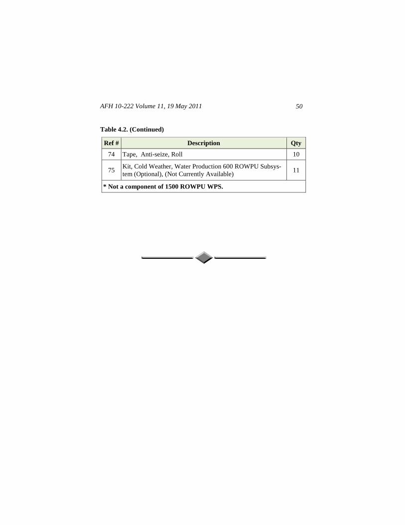
Table 4.2. (Continued)
Ref # Description Qty
74 Tape, Anti-seize, Roll 10
75 Kit, Cold Weather, Water Production 600 ROWPU Subsys-
tem (Optional), (Not Currently Available) 11
* Not a component of 1500 ROWPU WPS.
AFH 10-222 Volume 11, 19 May 2011 51
Chapter 5
550-INITIAL SUBSYSTEM
5.1. General Information. The 550-Initial Subsystem is the primary potable
water distribution subsystem of the contingency water system. The subsystem
may be deployed as a stand-alone potable water distribution subsystem;
however, it is designed for expansion and buildup to meet varying user
deployment and operational needs. The 550-Initial Subsystem (Figure 5.1)
normally receives potable water input from the Water Production Subsystem
discussed in Chapter 4. However, the adapters supplied with this subsystem
do provide a means to draw potable water from other similar potable water
sources. Potable water input to the subsystem is typically distributed to three
20,000-gallon fabric tanks for storage. The storage tanks, usually in tank farm
configuration, distribute the potable water to a variable speed dual pumping
station. The two pumps are parallel configured, enabling dual or single pump
operation, and single pump isolation for maintenance or repair purposes. The
remaining operational pump maintains water pressure in the distribution line.
Output from the pumping station is applied to a distribution line that is looped
and connected together to form a pressurized feed line. User facilities, such as
latrines, showers, and laundries, are branch fed from the pressurized feed line.
Waste output from the user facilities is processed by various lift pumps and
wastewater lines that distribute the wastewater to a wastewater collection
tank for disposal. Hose rollover protection ramps (hose bridges) are provided
in the event potable water distribution and/or wastewater distribution requires
crossing roadways or similar heavy vehicular traffic areas.
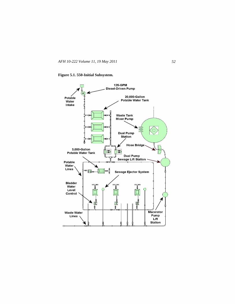
5.2. Components. The major components that make up the 550-Initial
Subsystem are illustrated in Figure 5.1 and listed in Table 5.1. However, for
a complete list of all subsystem components, including nomenclature and
quantity per subsystem, refer to Table 5.4 in this handbook and the 550-
Initial Subsystem IPB in T.O. 40W4-21-1.
AFH 10-222 Volume 11, 19 May 2011
52
Figure 5.1. 550-Initial Subsystem.
AFH 10-222 Volume 11, 19 May 2011 53
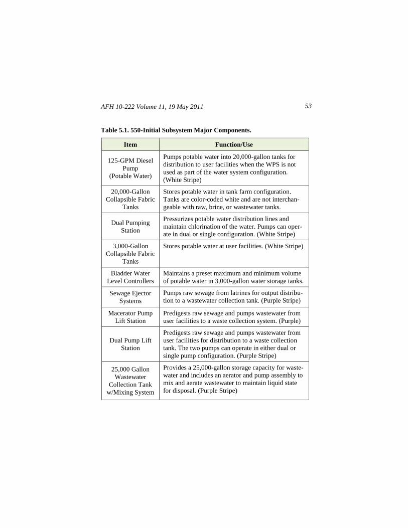
Table 5.1. 550-Initial Subsystem Major Components.
Item Function/Use
125-GPM Diesel
Pump
(Potable Water)
Pumps potable water into 20,000-gallon tanks for
distribution to user facilities when the WPS is not
used as part of the water system configuration.
(White Stripe)
20,000-Gallon
Collapsible Fabric
Tanks
Stores potable water in tank farm configuration.
Tanks are color-coded white and are not interchan-
geable with raw, brine, or wastewater tanks.
Dual Pumping
Station
Pressurizes potable water distribution lines and
maintain chlorination of the water. Pumps can oper-
ate in dual or single configuration. (White Stripe)
3,000-Gallon
Collapsible Fabric
Tanks
Stores potable water at user facilities. (White Stripe)
Bladder Water
Level Controllers
Maintains a preset maximum and minimum volume
of potable water in 3,000-gallon water storage tanks.
Sewage Ejector
Systems
Pumps raw sewage from latrines for output distribu-
tion to a wastewater collection tank. (Purple Stripe)
Macerator Pump
Lift Station
Predigests raw sewage and pumps wastewater from
user facilities to a waste collection system. (Purple)
Dual Pump Lift
Station
Predigests raw sewage and pumps wastewater from
user facilities for distribution to a waste collection
tank. The two pumps can operate in either dual or
single pump configuration. (Purple Stripe)
25,000 Gallon
Wastewater
Collection Tank
w/Mixing System
Provides a 25,000-gallon storage capacity for waste-
water and includes an aerator and pump assembly to
mix and aerate wastewater to maintain liquid state
for disposal. (Purple Stripe)
AFH 10-222 Volume 11, 19 May 2011
54
Table 5.1. (Continued)
Item Function/Use
Hose Bridge
System
Provides rollover protection for potable water and/
or wastewater distribution hoses when routed across
roadways or similar heavy vehicular traffic areas.
Hoses
Route potable water to storage or user facilities, and
routes wastewater for disposal. The hoses are color-
coded white for potable water and purple for waste-
water.
Ball Valves
Controls potable water flow. Also used to isolate
water flow to specific components and user facilities
to help facilitate maintenance and/or repair actions.
Check Valves
(Wastewater)
Prevents waste from flowing back into the facilities,
minimizes spills from unforeseen ruptures, and
prevents sewage pump systems from over tasking.
5.3. Installation. Before installing the 550-Initial Subsystem, review the
planned dimensions of the water operations area (see Table 2.1on page 15)
and the orientation of the subsystem in relation to the remaining subsystems.
Then, refer to component layout diagrams in this chapter and the list in Table
5.4 to identify each numbered component when performing the steps below.
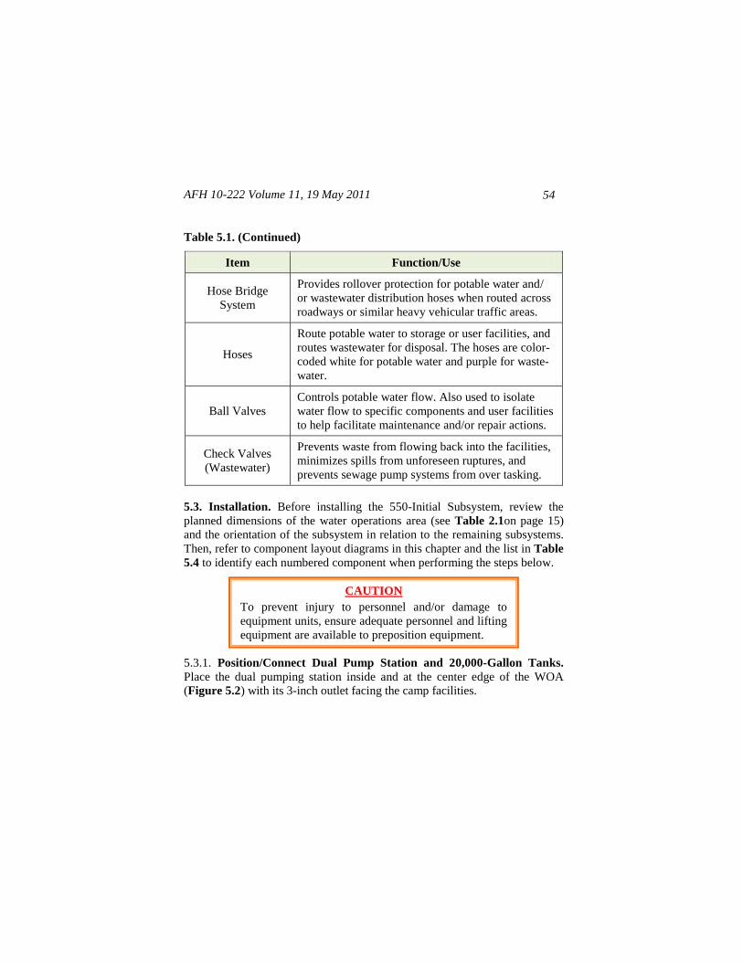
5.3.1. Position/Connect Dual Pump Station and 20,000-Gallon Tanks.
Place the dual pumping station inside and at the center edge of the WOA
(Figure 5.2) with its 3-inch outlet facing the camp facilities.
CAUTION
To prevent injury to personnel and/or damage to
equipment units, ensure adequate personnel and lifting
equipment are available to preposition equipment.
AFH 10-222 Volume 11, 19 May 2011 55
Figure 5.2. Siting Dual Pump Station and 20,000-Gallon Tanks (Typical).
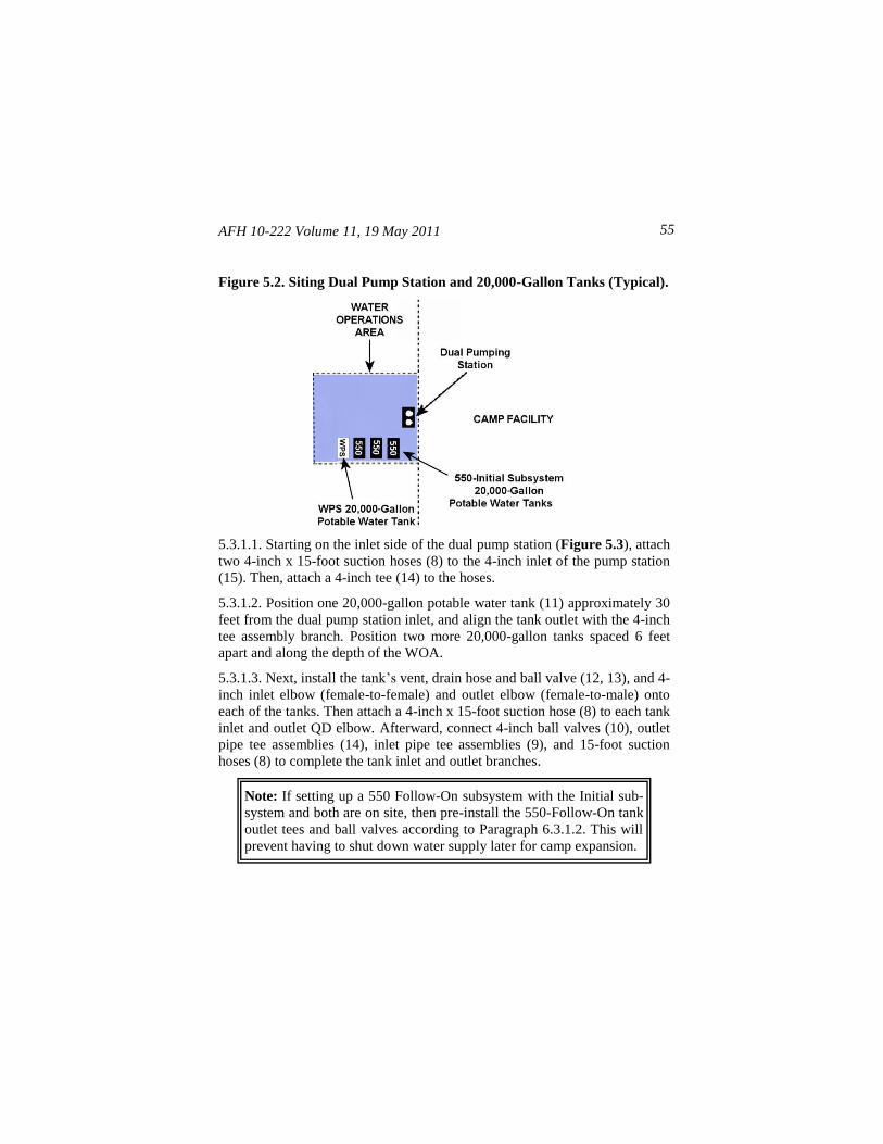
5.3.1.1. Starting on the inlet side of the dual pump station (Figure 5.3), attach
two 4-inch x 15-foot suction hoses (8) to the 4-inch inlet of the pump station
(15). Then, attach a 4-inch tee (14) to the hoses.
5.3.1.2. Position one 20,000-gallon potable water tank (11) approximately 30
feet from the dual pump station inlet, and align the tank outlet with the 4-inch
tee assembly branch. Position two more 20,000-gallon tanks spaced 6 feet
apart and along the depth of the WOA.
5.3.1.3. Next, install the tank’s vent, drain hose and ball valve (12, 13), and 4-
inch inlet elbow (female-to-female) and outlet elbow (female-to-male) onto
each of the tanks. Then attach a 4-inch x 15-foot suction hose (8) to each tank
inlet and outlet QD elbow. Afterward, connect 4-inch ball valves (10), outlet
pipe tee assemblies (14), inlet pipe tee assemblies (9), and 15-foot suction
hoses (8) to complete the tank inlet and outlet branches.
Note: If setting up a 550 Follow-On subsystem with the Initial sub-
system and both are on site, then pre-install the 550-Follow-On tank
outlet tees and ball valves according to Paragraph 6.3.1.2. This will
prevent having to shut down water supply later for camp expansion.
AFH 10-222 Volume 11, 19 May 2011
56
Note: When installing the sewage ejector system, a backhoe or
similar digging equipment may be necessary for excavation and
backfill operations.
Figure 5.3. 550-Initial Subsystem Dual Pump Station and 20,000-Gallon
Potable Water Tanks Basic Component Layout.
5.3.1.4. Link the 550-Initial potable water tanks and the WPS potable water
tank together by connecting the 4-inch x 15-foot suction hoses from the WPS
tank to the inlet and outlet branches of the 550-Initial tanks, resulting in a
four-tank farm configuration.
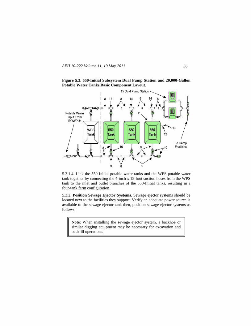
5.3.2. Position Sewage Ejector Systems. Sewage ejector systems should be
located next to the facilities they support. Verify an adequate power source is
available to the sewage ejector tank then, position sewage ejector systems as
follows:
AFH 10-222 Volume 11, 19 May 2011 57
5.3.2.1. Position sewage ejector systems alongside latrine facilities (Figure
5.4). To determine the exact location, first set up the latrine's drain system to
verify its exact ending point. Then, assemble the inlet and outlet components
to the sewage ejector tank and excavate a hole for the tank.
Figure 5.4. Sewage Ejector System Placement (Typical).
5.3.2.2. Excavate a hole large enough to accommodate the station tank to a
depth of at least 24 inches. Prepare the bottom of the hole with 6 inches of
backfill material of gravel or stone that is not less than 3/8 inch in diameter or
larger than 3/4 inch in diameter (if available). Ensure the base is level and
smooth.
CAUTION
In freezing conditions, backfill material must be dry
and free of ice. Do not use other backfill materials
unless approved by the manufacturer.
CAUTION
Damage and/or destruction of Sewage Ejector System
(Latrine) tank will result if accidental tip-over occurs due
to equipment or similar contact occurring as the result of
ground-level installation. To prevent tip-over damage, the
tank should be installed in-ground to a depth of 24 inches.
AFH 10-222 Volume 11, 19 May 2011
58
5.3.2.3. Lower the sewage ejector tank into the hole and insert backfill
material until it reaches ground level.
5.3.3. Position 3,000-Gallon Potable Water Tanks. Position 3,000-gallon
potable water tanks (24) next to their respective facilities (Figure 5.5) as
follows:
5.3.3.1. Position one 3,000-gallon potable water tank about 25 feet away from
the kitchen facility’s water connection. Position additional 3,000-gallon tanks
approximately 25 feet away and centered between each of the two
shower/shave and latrine facilities. Each tank will feed one shower/shave and
one latrine facility.
5.3.3.2. Position another 3,000-gallon tank directly behind and approximately
25 feet away from the laundry facility. Afterward, connect all vents and drain
assemblies to the 3,000-gallon tanks. If a BEAR Laundry facility is used, it
comes equipped with its own 3,000-gallon tank that may be used in lieu of
the tank from the 550-Initial Subsystem.
Figure 5.5. 3,000-Gallon Potable Water Tank at User Facility.
Note: Always ensure neoprene gaskets are in place before connect-
ing suction or discharge hoses.
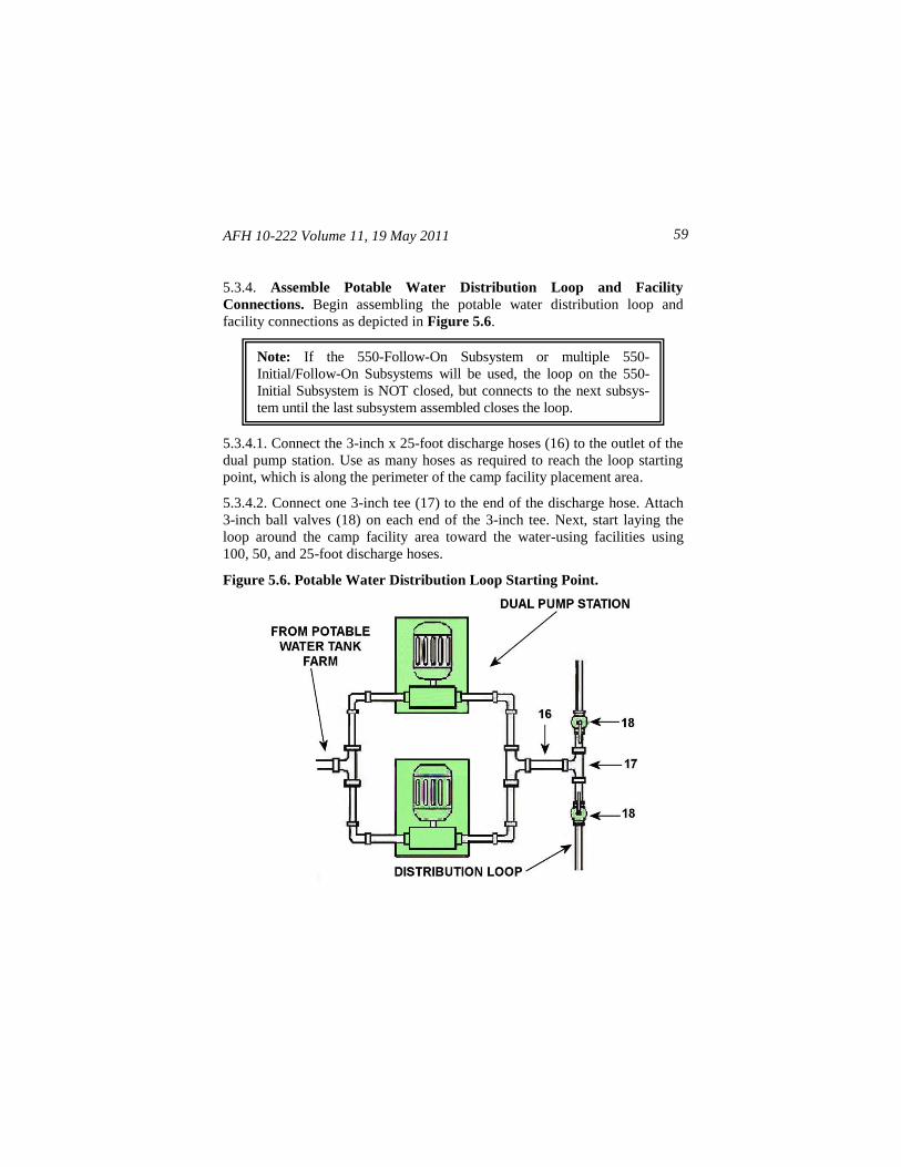
AFH 10-222 Volume 11, 19 May 2011 59
5.3.4. Assemble Potable Water Distribution Loop and Facility
Connections. Begin assembling the potable water distribution loop and
facility connections as depicted in Figure 5.6.
5.3.4.1. Connect the 3-inch x 25-foot discharge hoses (16) to the outlet of the
dual pump station. Use as many hoses as required to reach the loop starting
point, which is along the perimeter of the camp facility placement area.
5.3.4.2. Connect one 3-inch tee (17) to the end of the discharge hose. Attach
3-inch ball valves (18) on each end of the 3-inch tee. Next, start laying the
loop around the camp facility area toward the water-using facilities using
100, 50, and 25-foot discharge hoses.
Figure 5.6. Potable Water Distribution Loop Starting Point.
Note: If the 550-Follow-On Subsystem or multiple 550-
Initial/Follow-On Subsystems will be used, the loop on the 550-
Initial Subsystem is NOT closed, but connects to the next subsys-
tem until the last subsystem assembled closes the loop.
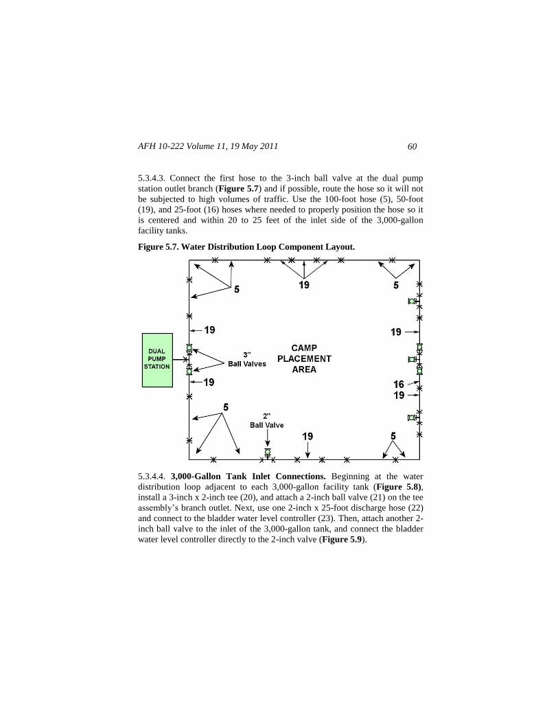
AFH 10-222 Volume 11, 19 May 2011
60
5.3.4.3. Connect the first hose to the 3-inch ball valve at the dual pump
station outlet branch (Figure 5.7) and if possible, route the hose so it will not
be subjected to high volumes of traffic. Use the 100-foot hose (5), 50-foot
(19), and 25-foot (16) hoses where needed to properly position the hose so it
is centered and within 20 to 25 feet of the inlet side of the 3,000-gallon
facility tanks.
Figure 5.7. Water Distribution Loop Component Layout.
5.3.4.4. 3,000-Gallon Tank Inlet Connections. Beginning at the water
distribution loop adjacent to each 3,000-gallon facility tank (Figure 5.8),
install a 3-inch x 2-inch tee (20), and attach a 2-inch ball valve (21) on the tee
assembly’s branch outlet. Next, use one 2-inch x 25-foot discharge hose (22)
and connect to the bladder water level controller (23). Then, attach another 2-
inch ball valve to the inlet of the 3,000-gallon tank, and connect the bladder
water level controller directly to the 2-inch valve (Figure 5.9).
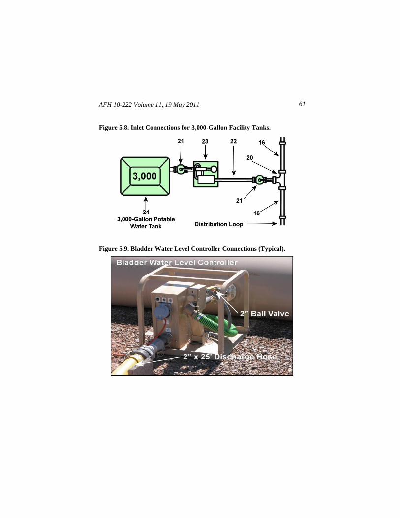
AFH 10-222 Volume 11, 19 May 2011 61
Figure 5.8. Inlet Connections for 3,000-Gallon Facility Tanks.
Figure 5.9. Bladder Water Level Controller Connections (Typical).
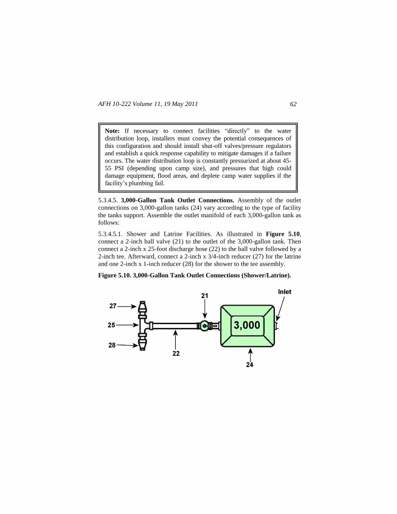
AFH 10-222 Volume 11, 19 May 2011
62
5.3.4.5. 3,000-Gallon Tank Outlet Connections. Assembly of the outlet
connections on 3,000-gallon tanks (24) vary according to the type of facility
the tanks support. Assemble the outlet manifold of each 3,000-gallon tank as
follows:
5.3.4.5.1. Shower and Latrine Facilities. As illustrated in Figure 5.10,
connect a 2-inch ball valve (21) to the outlet of the 3,000-gallon tank. Then
connect a 2-inch x 25-foot discharge hose (22) to the ball valve followed by a
2-inch tee. Afterward, connect a 2-inch x 3/4-inch reducer (27) for the latrine
and one 2-inch x 1-inch reducer (28) for the shower to the tee assembly.
Figure 5.10. 3,000-Gallon Tank Outlet Connections (Shower/Latrine).
Note: If necessary to connect facilities ―directly‖ to the water
distribution loop, installers must convey the potential consequences of
this configuration and should install shut-off valves/pressure regulators
and establish a quick response capability to mitigate damages if a failure
occurs. The water distribution loop is constantly pressurized at about 45-
55 PSI (depending upon camp size), and pressures that high could
damage equipment, flood areas, and deplete camp water supplies if the
facility’s plumbing fail.
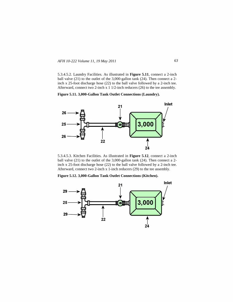
AFH 10-222 Volume 11, 19 May 2011 63
5.3.4.5.2. Laundry Facilities. As illustrated in Figure 5.11, connect a 2-inch
ball valve (21) to the outlet of the 3,000-gallon tank (24). Then connect a 2-
inch x 25-foot discharge hose (22) to the ball valve followed by a 2-inch tee.
Afterward, connect two 2-inch x 1 1/2-inch reducers (26) to the tee assembly.
Figure 5.11. 3,000-Gallon Tank Outlet Connections (Laundry).
5.3.4.5.3. Kitchen Facilities. As illustrated in Figure 5.12, connect a 2-inch
ball valve (21) to the outlet of the 3,000-gallon tank (24). Then connect a 2-
inch x 25-foot discharge hose (22) to the ball valve followed by a 2-inch tee.
Afterward, connect two 2-inch x 1-inch reducers (29) to the tee assembly.
Figure 5.12. 3,000-Gallon Tank Outlet Connections (Kitchen).
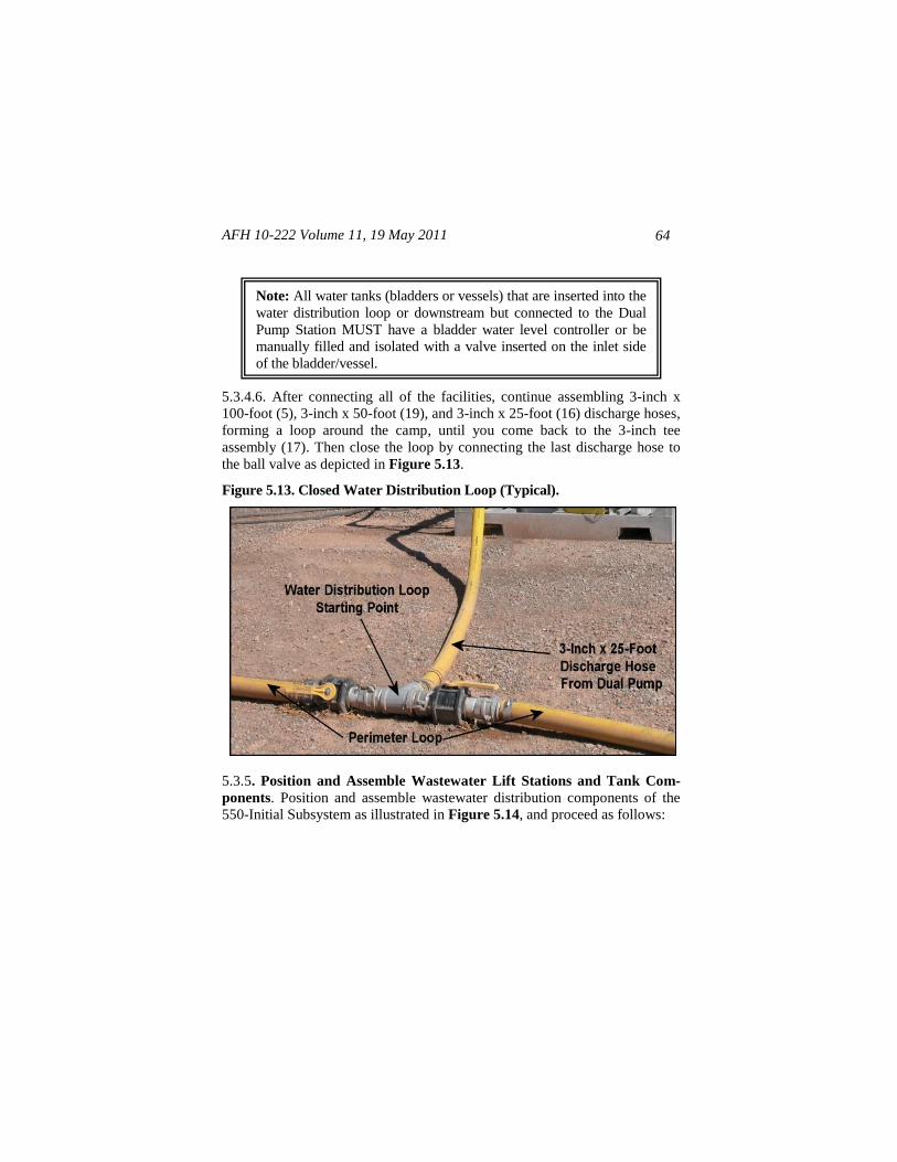
AFH 10-222 Volume 11, 19 May 2011
64
5.3.4.6. After connecting all of the facilities, continue assembling 3-inch x
100-foot (5), 3-inch x 50-foot (19), and 3-inch x 25-foot (16) discharge hoses,
forming a loop around the camp, until you come back to the 3-inch tee
assembly (17). Then close the loop by connecting the last discharge hose to
the ball valve as depicted in Figure 5.13.
Figure 5.13. Closed Water Distribution Loop (Typical).
5.3.5. Position and Assemble Wastewater Lift Stations and Tank Com-
ponents. Position and assemble wastewater distribution components of the
550-Initial Subsystem as illustrated in Figure 5.14, and proceed as follows:
Note: All water tanks (bladders or vessels) that are inserted into the
water distribution loop or downstream but connected to the Dual
Pump Station MUST have a bladder water level controller or be
manually filled and isolated with a valve inserted on the inlet side
of the bladder/vessel.
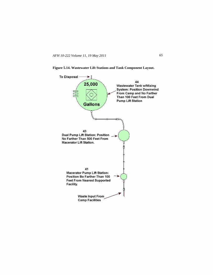
AFH 10-222 Volume 11, 19 May 2011 65
Figure 5.14. Wastewater Lift Stations and Tank Component Layout.
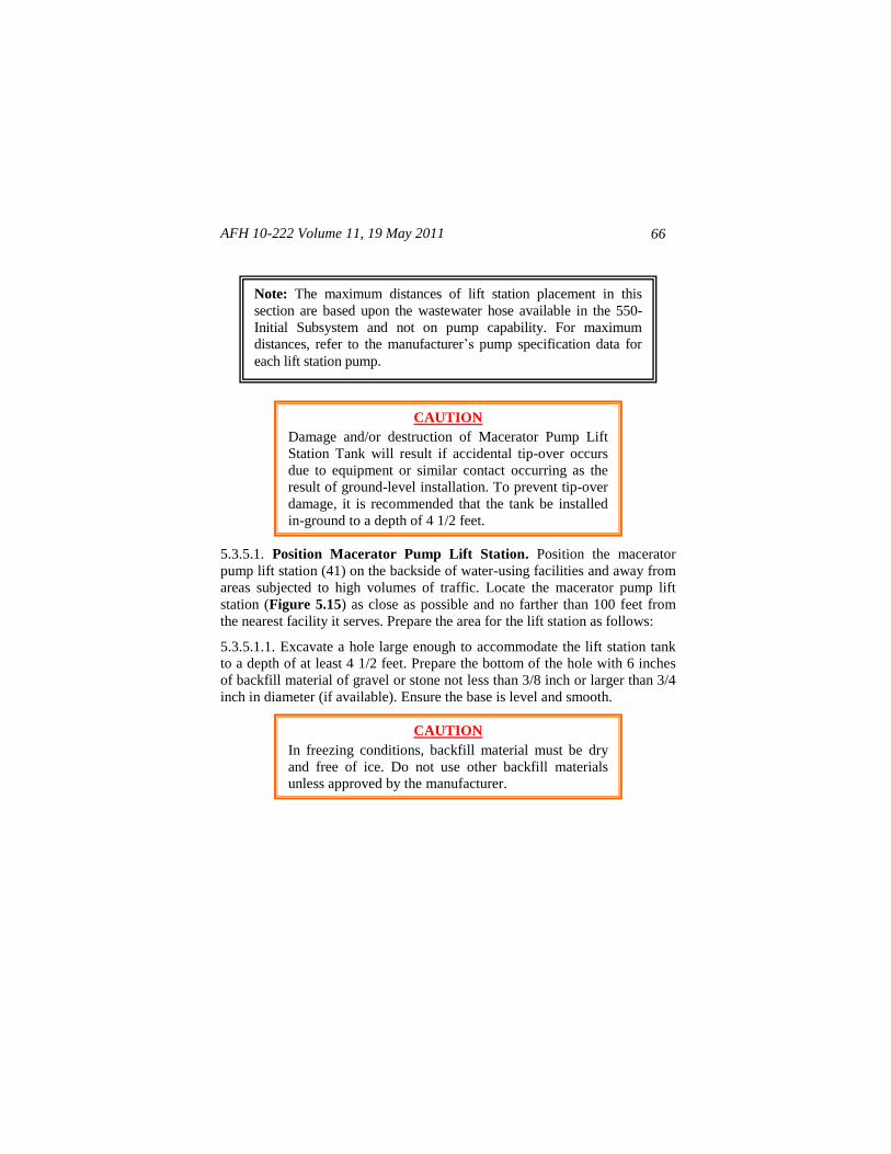
AFH 10-222 Volume 11, 19 May 2011
66
5.3.5.1. Position Macerator Pump Lift Station. Position the macerator
pump lift station (41) on the backside of water-using facilities and away from
areas subjected to high volumes of traffic. Locate the macerator pump lift
station (Figure 5.15) as close as possible and no farther than 100 feet from
the nearest facility it serves. Prepare the area for the lift station as follows:
5.3.5.1.1. Excavate a hole large enough to accommodate the lift station tank
to a depth of at least 4 1/2 feet. Prepare the bottom of the hole with 6 inches
of backfill material of gravel or stone not less than 3/8 inch or larger than 3/4
inch in diameter (if available). Ensure the base is level and smooth.
CAUTION
In freezing conditions, backfill material must be dry
and free of ice. Do not use other backfill materials
unless approved by the manufacturer.
CAUTION
Damage and/or destruction of Macerator Pump Lift
Station Tank will result if accidental tip-over occurs
due to equipment or similar contact occurring as the
result of ground-level installation. To prevent tip-over
damage, it is recommended that the tank be installed
in-ground to a depth of 4 1/2 feet.
Note: The maximum distances of lift station placement in this
section are based upon the wastewater hose available in the 550-
Initial Subsystem and not on pump capability. For maximum
distances, refer to the manufacturer’s pump specification data for
each lift station pump.
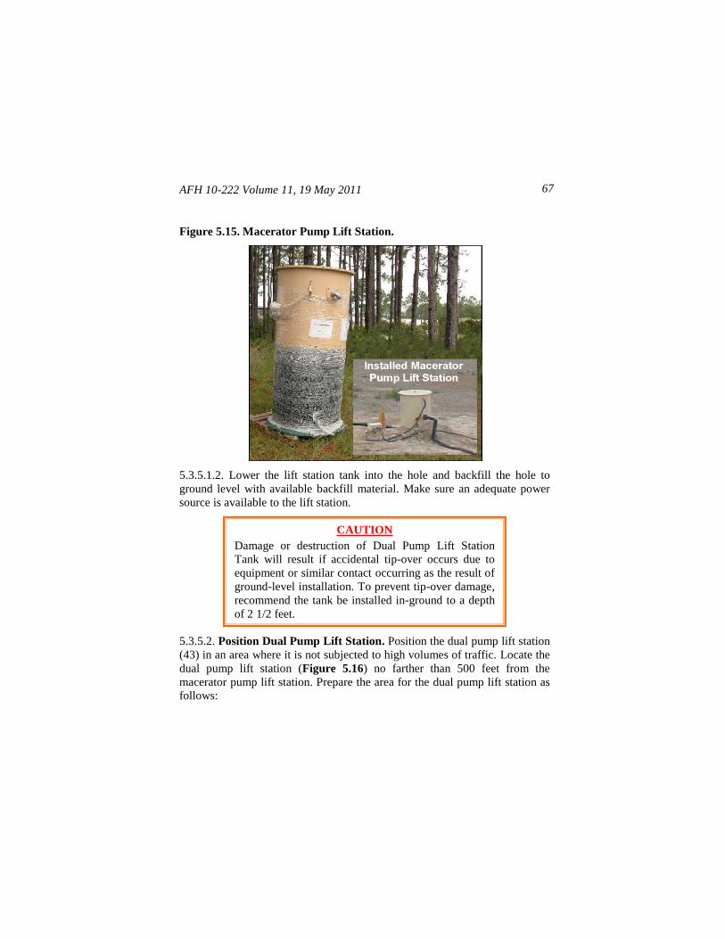
AFH 10-222 Volume 11, 19 May 2011 67
Figure 5.15. Macerator Pump Lift Station.
5.3.5.1.2. Lower the lift station tank into the hole and backfill the hole to
ground level with available backfill material. Make sure an adequate power
source is available to the lift station.
5.3.5.2. Position Dual Pump Lift Station. Position the dual pump lift station
(43) in an area where it is not subjected to high volumes of traffic. Locate the
dual pump lift station (Figure 5.16) no farther than 500 feet from the
macerator pump lift station. Prepare the area for the dual pump lift station as
follows:
CAUTION
Damage or destruction of Dual Pump Lift Station
Tank will result if accidental tip-over occurs due to
equipment or similar contact occurring as the result of
ground-level installation. To prevent tip-over damage,
recommend the tank be installed in-ground to a depth
of 2 1/2 feet.
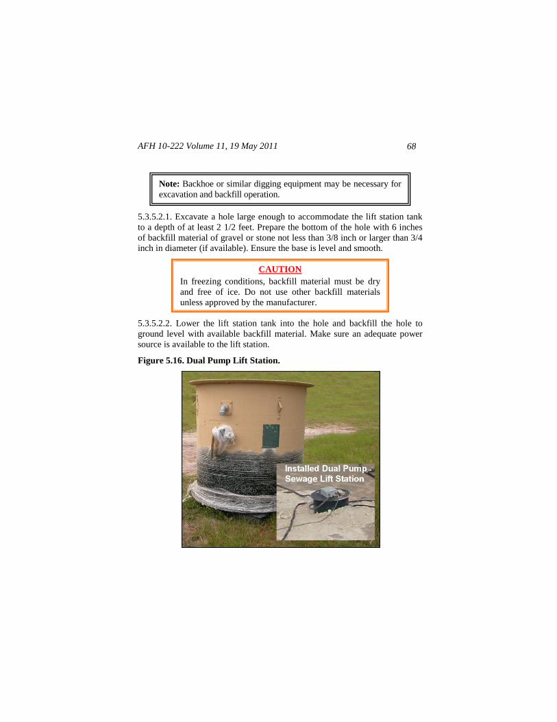
AFH 10-222 Volume 11, 19 May 2011
68
5.3.5.2.1. Excavate a hole large enough to accommodate the lift station tank
to a depth of at least 2 1/2 feet. Prepare the bottom of the hole with 6 inches
of backfill material of gravel or stone not less than 3/8 inch or larger than 3/4
inch in diameter (if available). Ensure the base is level and smooth.
5.3.5.2.2. Lower the lift station tank into the hole and backfill the hole to
ground level with available backfill material. Make sure an adequate power
source is available to the lift station.
Figure 5.16. Dual Pump Lift Station.
CAUTION
In freezing conditions, backfill material must be dry
and free of ice. Do not use other backfill materials
unless approved by the manufacturer.
Note: Backhoe or similar digging equipment may be necessary for
excavation and backfill operation.
AFH 10-222 Volume 11, 19 May 2011 69
5.3.5.3. Position and Assemble 25,000-Gallon Wastewater Collection
Tank. Determine the location for the 25,000-gallon wastewater collection
tank (44). Locate the tank (Figure 5.17) downwind of the camp and no
farther than 100 feet from the dual pump lift station (43). Ensure the area for
the tank is flat and level, circular, and at least 40 feet in diameter. Remove
any large rocks or sharp objects that could puncture the tank liner. Place the
wastewater collection tank components and mixing system components
adjacent to the selected location then proceed as follows:
5.3.5.3.1. Spread out the ground cloth, and verify there are no large wrinkles in
the cloth material—smooth out the cloth if necessary. Spread the tank liner on
the ground cloth, ensuring the liner is free of creases. When the liner is
positioned properly, place the aerator assembly in the center of the liner
material.
Figure 5.17. 25,000-Gallon Wastewater Collection Tank.
CAUTION
The wastewater mixing assembly (aerator) weighs
approximately 290 pounds. To prevent injury and/or
damage to equipment, ensure adequate (4 minimum)
personnel are available when positioning assembly
within 25,000-gallon tank liner.
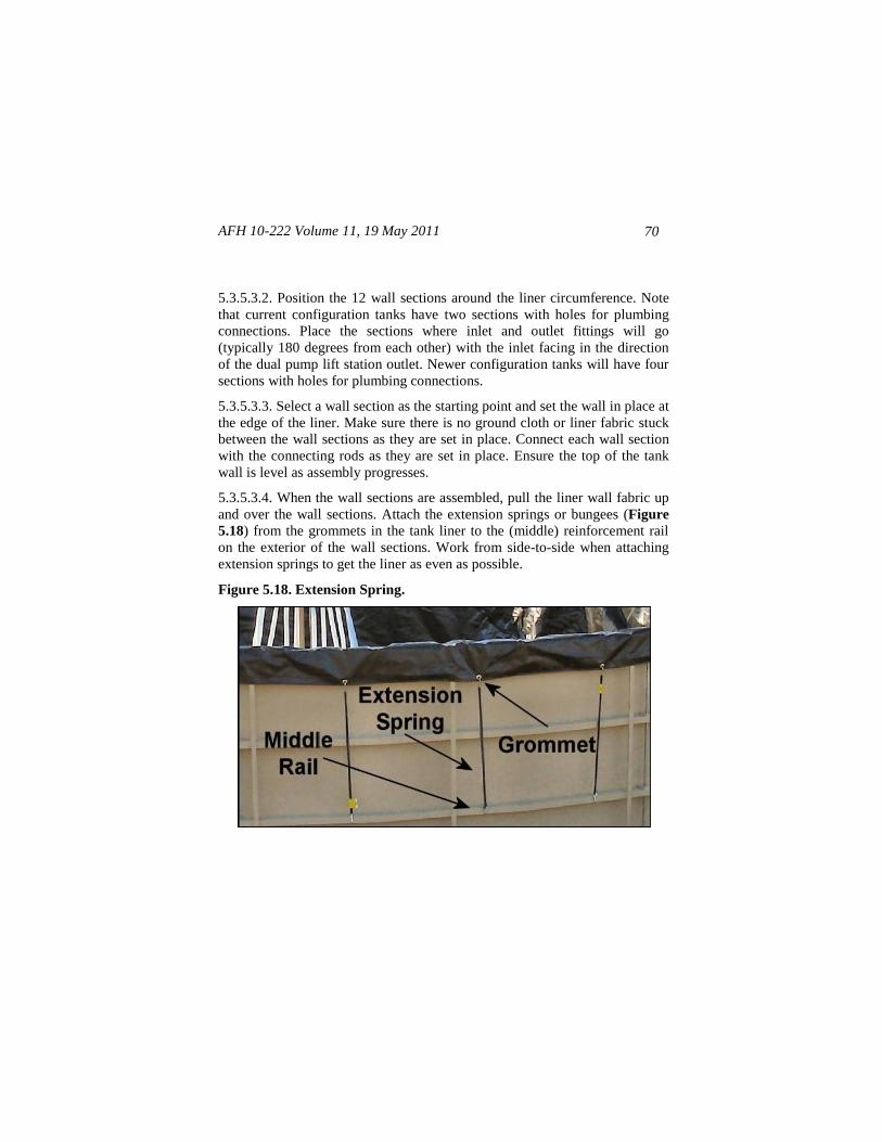
AFH 10-222 Volume 11, 19 May 2011
70
5.3.5.3.2. Position the 12 wall sections around the liner circumference. Note
that current configuration tanks have two sections with holes for plumbing
connections. Place the sections where inlet and outlet fittings will go
(typically 180 degrees from each other) with the inlet facing in the direction
of the dual pump lift station outlet. Newer configuration tanks will have four
sections with holes for plumbing connections.
5.3.5.3.3. Select a wall section as the starting point and set the wall in place at
the edge of the liner. Make sure there is no ground cloth or liner fabric stuck
between the wall sections as they are set in place. Connect each wall section
with the connecting rods as they are set in place. Ensure the top of the tank
wall is level as assembly progresses.
5.3.5.3.4. When the wall sections are assembled, pull the liner wall fabric up
and over the wall sections. Attach the extension springs or bungees (Figure
5.18) from the grommets in the tank liner to the (middle) reinforcement rail
on the exterior of the wall sections. Work from side-to-side when attaching
extension springs to get the liner as even as possible.
Figure 5.18. Extension Spring.
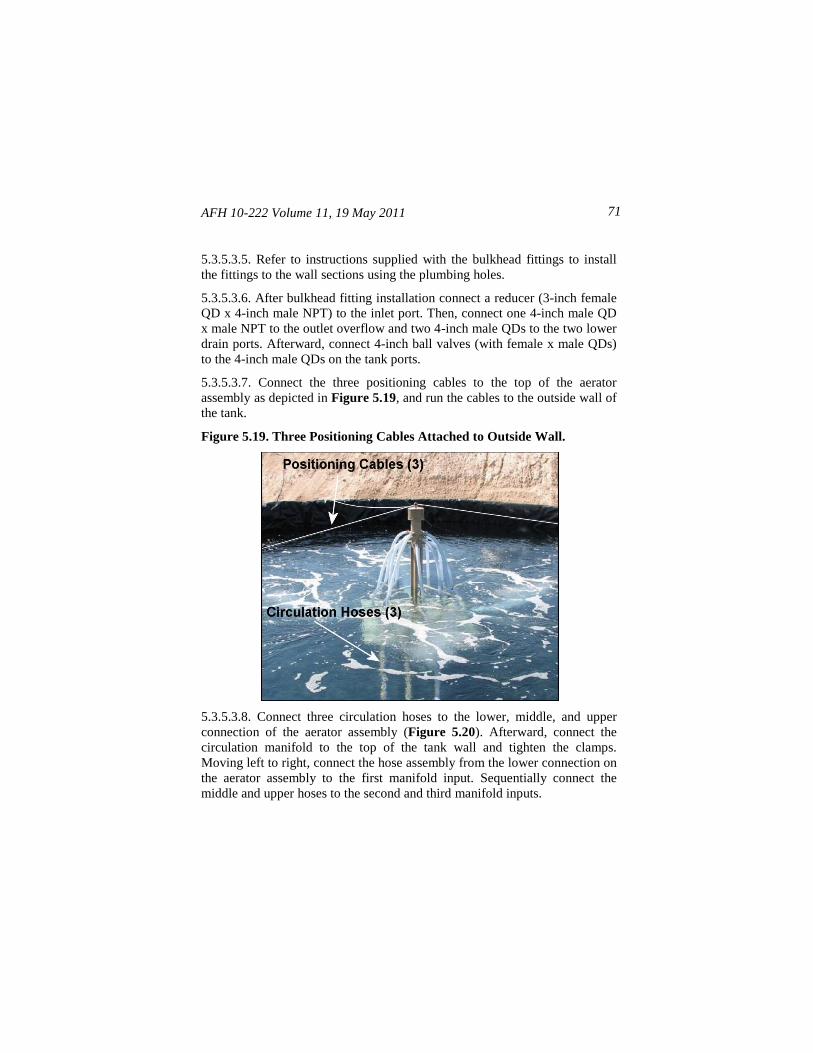
AFH 10-222 Volume 11, 19 May 2011 71
5.3.5.3.5. Refer to instructions supplied with the bulkhead fittings to install
the fittings to the wall sections using the plumbing holes.
5.3.5.3.6. After bulkhead fitting installation connect a reducer (3-inch female
QD x 4-inch male NPT) to the inlet port. Then, connect one 4-inch male QD
x male NPT to the outlet overflow and two 4-inch male QDs to the two lower
drain ports. Afterward, connect 4-inch ball valves (with female x male QDs)
to the 4-inch male QDs on the tank ports.
5.3.5.3.7. Connect the three positioning cables to the top of the aerator
assembly as depicted in Figure 5.19, and run the cables to the outside wall of
the tank.
Figure 5.19. Three Positioning Cables Attached to Outside Wall.
5.3.5.3.8. Connect three circulation hoses to the lower, middle, and upper
connection of the aerator assembly (Figure 5.20). Afterward, connect the
circulation manifold to the top of the tank wall and tighten the clamps.
Moving left to right, connect the hose assembly from the lower connection on
the aerator assembly to the first manifold input. Sequentially connect the
middle and upper hoses to the second and third manifold inputs.
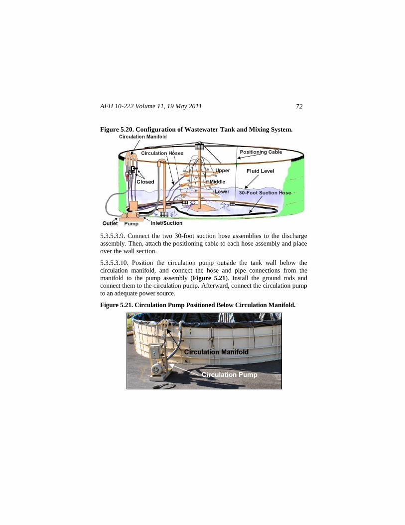
AFH 10-222 Volume 11, 19 May 2011
72
Figure 5.20. Configuration of Wastewater Tank and Mixing System.
5.3.5.3.9. Connect the two 30-foot suction hose assemblies to the discharge
assembly. Then, attach the positioning cable to each hose assembly and place
over the wall section.
5.3.5.3.10. Position the circulation pump outside the tank wall below the
circulation manifold, and connect the hose and pipe connections from the
manifold to the pump assembly (Figure 5.21). Install the ground rods and
connect them to the circulation pump. Afterward, connect the circulation pump
to an adequate power source.
Figure 5.21. Circulation Pump Positioned Below Circulation Manifold.
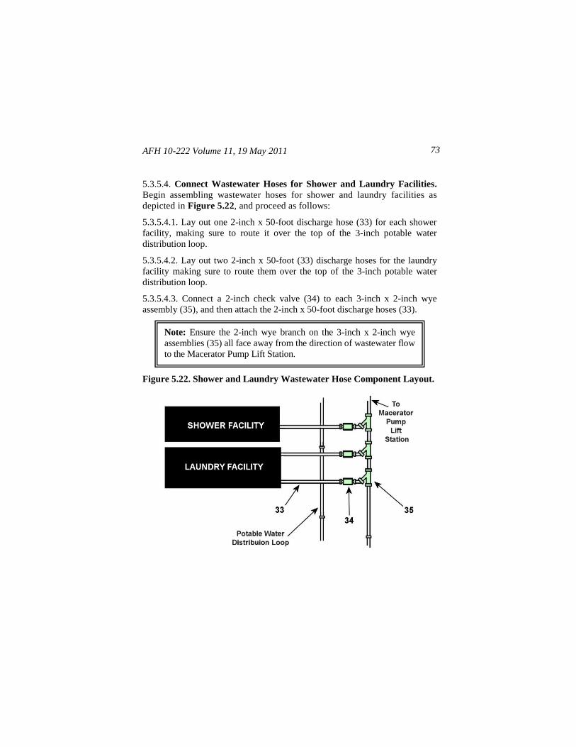
AFH 10-222 Volume 11, 19 May 2011 73
5.3.5.4. Connect Wastewater Hoses for Shower and Laundry Facilities.
Begin assembling wastewater hoses for shower and laundry facilities as
depicted in Figure 5.22, and proceed as follows:
5.3.5.4.1. Lay out one 2-inch x 50-foot discharge hose (33) for each shower
facility, making sure to route it over the top of the 3-inch potable water
distribution loop.
5.3.5.4.2. Lay out two 2-inch x 50-foot (33) discharge hoses for the laundry
facility making sure to route them over the top of the 3-inch potable water
distribution loop.
5.3.5.4.3. Connect a 2-inch check valve (34) to each 3-inch x 2-inch wye
assembly (35), and then attach the 2-inch x 50-foot discharge hoses (33).
Figure 5.22. Shower and Laundry Wastewater Hose Component Layout.
Note: Ensure the 2-inch wye branch on the 3-inch x 2-inch wye
assemblies (35) all face away from the direction of wastewater flow
to the Macerator Pump Lift Station.
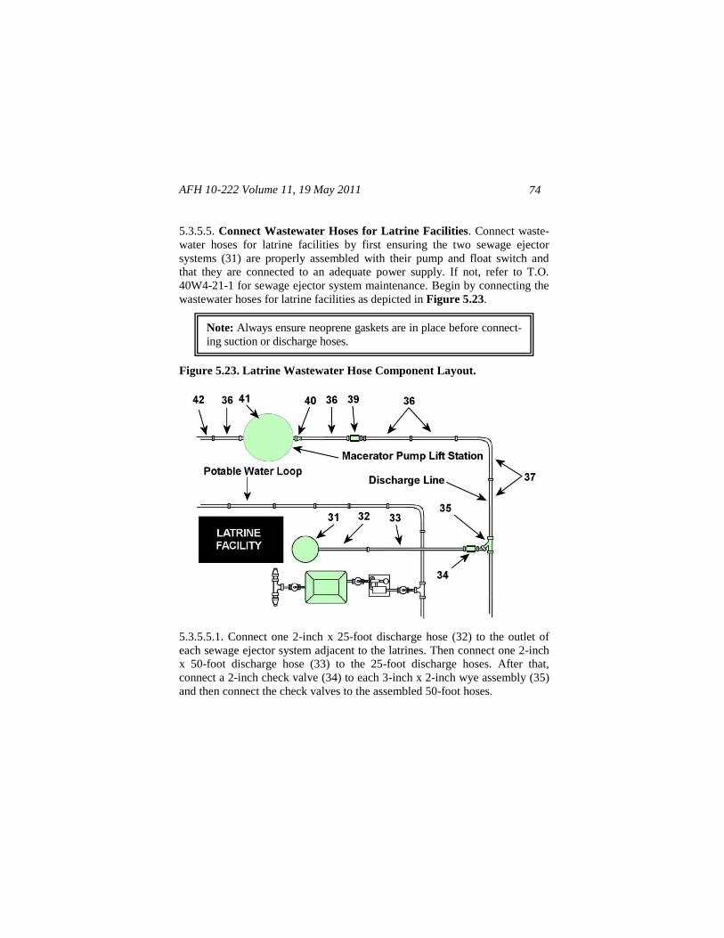
AFH 10-222 Volume 11, 19 May 2011
74
5.3.5.5. Connect Wastewater Hoses for Latrine Facilities. Connect waste-
water hoses for latrine facilities by first ensuring the two sewage ejector
systems (31) are properly assembled with their pump and float switch and
that they are connected to an adequate power supply. If not, refer to T.O.
40W4-21-1 for sewage ejector system maintenance. Begin by connecting the
wastewater hoses for latrine facilities as depicted in Figure 5.23.
Figure 5.23. Latrine Wastewater Hose Component Layout.
5.3.5.5.1. Connect one 2-inch x 25-foot discharge hose (32) to the outlet of
each sewage ejector system adjacent to the latrines. Then connect one 2-inch
x 50-foot discharge hose (33) to the 25-foot discharge hoses. After that,
connect a 2-inch check valve (34) to each 3-inch x 2-inch wye assembly (35)
and then connect the check valves to the assembled 50-foot hoses.
Note: Always ensure neoprene gaskets are in place before connect-
ing suction or discharge hoses.
AFH 10-222 Volume 11, 19 May 2011 75
5.3.5.5.2. Connect all wye assemblies together using necessary lengths of
3-inch discharge hoses (36, 37), and assemble the hoses until you are within
25 feet of the macerator pump lift station (41).
5.3.5.5.3. At the macerator pump lift station (41), install one 4-inch x 3-inch
reducer (40) onto the inlet of the lift station and attach a 3-inch x 25-foot
discharge hose (36) onto the reducer. Fasten a 3-inch check valve (39) onto
the discharge hose and connect the check valve to the discharge hose coming
from the facilities.
5.3.5.5.4. Connect one 3-inch x 25-foot discharge hose (36) to the outlet of
the macerator pump lift station, and then attach enough 3-inch x 100-foot
discharge hose assemblies (42) and other 3-inch discharge hose assemblies
(36, 37) until you are approximately 25 feet from the dual pump lift station.
5.3.5.6. Assemble Dual Pump Lift Station Inlet and Outlet Branches. Begin
assembling the dual pump lift station inlet and outlet branches as depicted in
Figure 5.24.
5.3.5.6.1. Starting at the dual pump lift station (43), attach one 4-inch x 3-inch
reducer (40) onto the inlet of the lift station, followed by a 3-inch x 25-foot
discharge hose (36). Fasten a 3-inch check valve (39) onto the discharge hose
and connect the check valve to the discharge hose coming from the macerator
pump lift station.
5.3.5.6.2. At the dual pump lift station outlet, connect one 3-inch x 25-foot
discharge hose (36), followed by a 3-inch check valve (39). Then attach
enough 3-inch discharge hoses (37) from the check valve to reach the inlet
of the 25,000-gallon wastewater collection tank (44).
5.3.5.6.3. At the upper port ball valve outlet of the 25,000-gallon wastewater
collection tank, connect the desired number of 4-inch x 50-foot discharge hose
assemblies (45) to serve as the wastewater tank overflow.
Note: If the 550-Follow-On Subsystem is going to be used, the 3-
inch check valve assembly (39) will attach to a 3-inch tee assembly
(Waste), supplied with the 550-Follow-On Subsystem.
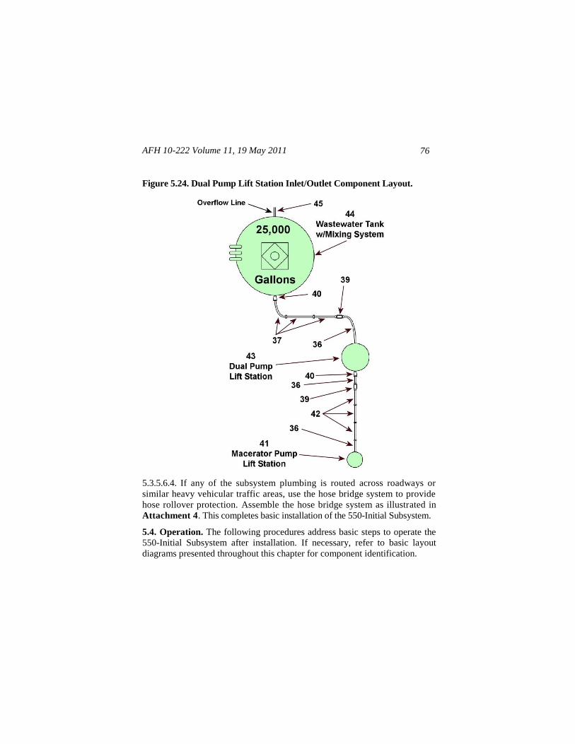
AFH 10-222 Volume 11, 19 May 2011
76
Figure 5.24. Dual Pump Lift Station Inlet/Outlet Component Layout.
5.3.5.6.4. If any of the subsystem plumbing is routed across roadways or
similar heavy vehicular traffic areas, use the hose bridge system to provide
hose rollover protection. Assemble the hose bridge system as illustrated in
Attachment 4. This completes basic installation of the 550-Initial Subsystem.
5.4. Operation. The following procedures address basic steps to operate the
550-Initial Subsystem after installation. If necessary, refer to basic layout
diagrams presented throughout this chapter for component identification.
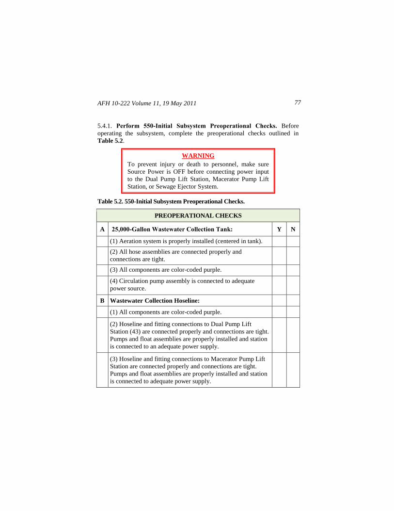
AFH 10-222 Volume 11, 19 May 2011 77
5.4.1. Perform 550-Initial Subsystem Preoperational Checks. Before
operating the subsystem, complete the preoperational checks outlined in
Table 5.2.
Table 5.2. 550-Initial Subsystem Preoperational Checks.
PREOPERATIONAL CHECKS
A 25,000-Gallon Wastewater Collection Tank: Y N
(1) Aeration system is properly installed (centered in tank).
(2) All hose assemblies are connected properly and
connections are tight.
(3) All components are color-coded purple.
(4) Circulation pump assembly is connected to adequate
power source.
B Wastewater Collection Hoseline:
(1) All components are color-coded purple.
(2) Hoseline and fitting connections to Dual Pump Lift
Station (43) are connected properly and connections are tight.
Pumps and float assemblies are properly installed and station
is connected to an adequate power supply.
(3) Hoseline and fitting connections to Macerator Pump Lift
Station are connected properly and connections are tight.
Pumps and float assemblies are properly installed and station
is connected to adequate power supply.
WARNING
To prevent injury or death to personnel, make sure
Source Power is OFF before connecting power input
to the Dual Pump Lift Station, Macerator Pump Lift
Station, or Sewage Ejector System.
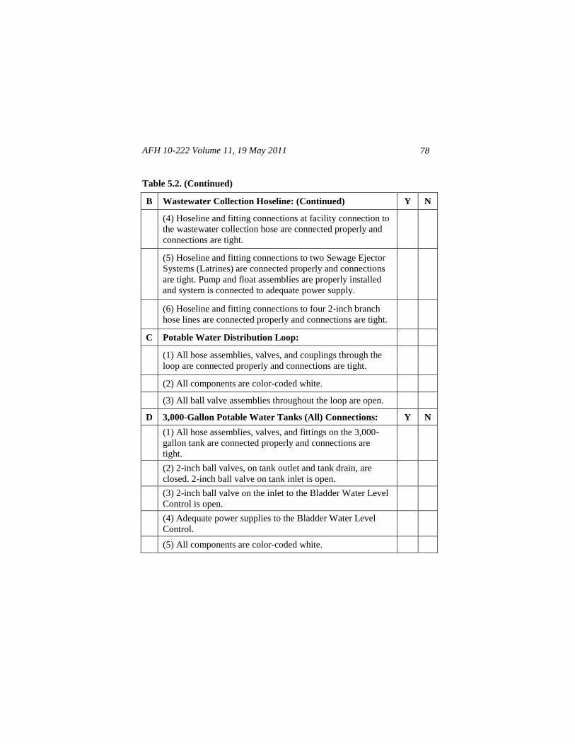
AFH 10-222 Volume 11, 19 May 2011
78
Table 5.2. (Continued)
B Wastewater Collection Hoseline: (Continued) Y N
(4) Hoseline and fitting connections at facility connection to
the wastewater collection hose are connected properly and
connections are tight.
(5) Hoseline and fitting connections to two Sewage Ejector
Systems (Latrines) are connected properly and connections
are tight. Pump and float assemblies are properly installed
and system is connected to adequate power supply.
(6) Hoseline and fitting connections to four 2-inch branch
hose lines are connected properly and connections are tight.
C Potable Water Distribution Loop:
(1) All hose assemblies, valves, and couplings through the
loop are connected properly and connections are tight.
(2) All components are color-coded white.
(3) All ball valve assemblies throughout the loop are open.
D 3,000-Gallon Potable Water Tanks (All) Connections: Y N
(1) All hose assemblies, valves, and fittings on the 3,000-
gallon tank are connected properly and connections are
tight.
(2) 2-inch ball valves, on tank outlet and tank drain, are
closed. 2-inch ball valve on tank inlet is open.
(3) 2-inch ball valve on the inlet to the Bladder Water Level
Control is open.
(4) Adequate power supplies to the Bladder Water Level
Control.
(5) All components are color-coded white.
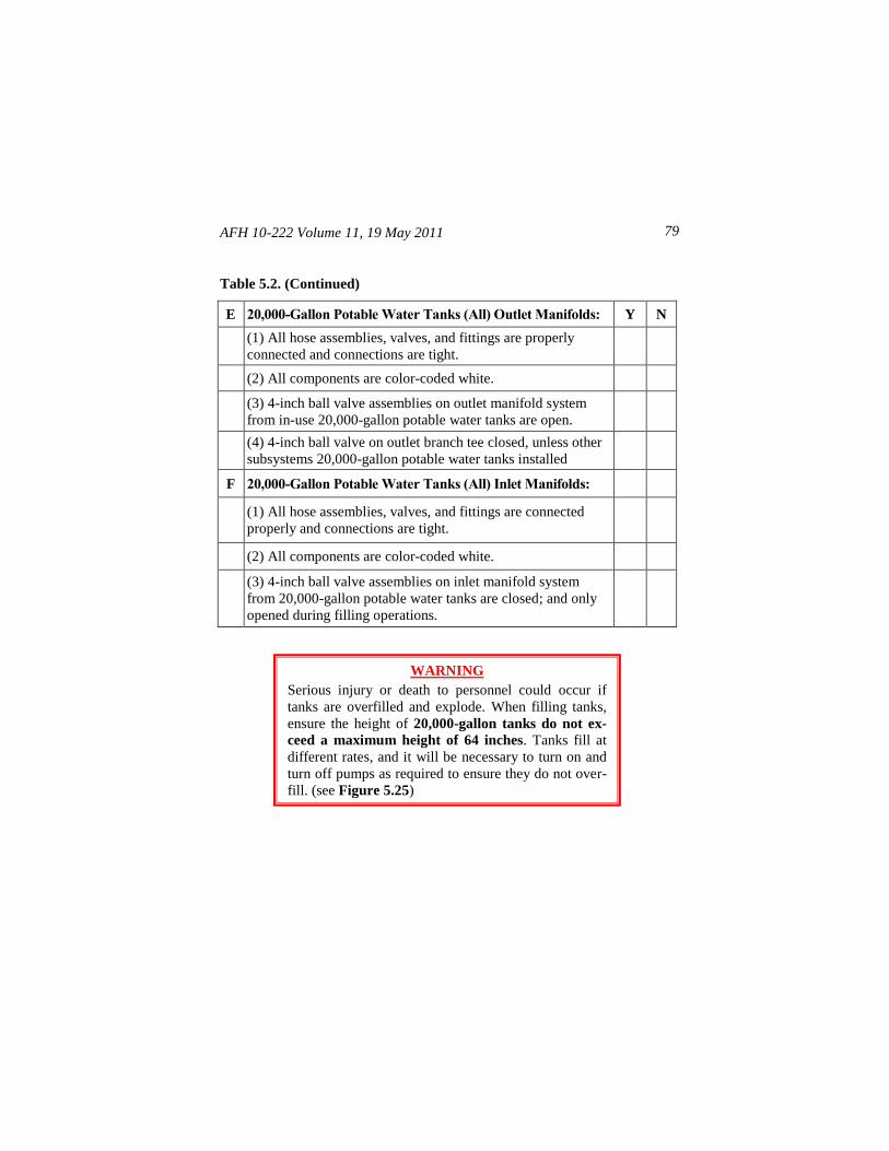
AFH 10-222 Volume 11, 19 May 2011 79
Table 5.2. (Continued)
E 20,000-Gallon Potable Water Tanks (All) Outlet Manifolds: Y N
(1) All hose assemblies, valves, and fittings are properly
connected and connections are tight.
(2) All components are color-coded white.
(3) 4-inch ball valve assemblies on outlet manifold system
from in-use 20,000-gallon potable water tanks are open.
(4) 4-inch ball valve on outlet branch tee closed, unless other
subsystems 20,000-gallon potable water tanks installed
F 20,000-Gallon Potable Water Tanks (All) Inlet Manifolds:
(1) All hose assemblies, valves, and fittings are connected
properly and connections are tight.
(2) All components are color-coded white.
(3) 4-inch ball valve assemblies on inlet manifold system
from 20,000-gallon potable water tanks are closed; and only
opened during filling operations.
WARNING
Serious injury or death to personnel could occur if
tanks are overfilled and explode. When filling tanks,
ensure the height of 20,000-gallon tanks do not ex-
ceed a maximum height of 64 inches. Tanks fill at
different rates, and it will be necessary to turn on and
turn off pumps as required to ensure they do not over-
fill. (see Figure 5.25)
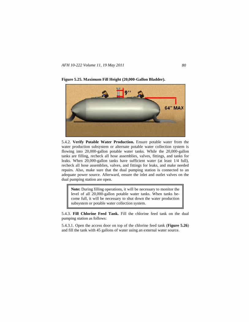
AFH 10-222 Volume 11, 19 May 2011
80
Figure 5.25. Maximum Fill Height (20,000-Gallon Bladder).
5.4.2. Verify Potable Water Production. Ensure potable water from the
water production subsystem or alternate potable water collection system is
flowing into 20,000-gallon potable water tanks. While the 20,000-gallon
tanks are filling, recheck all hose assemblies, valves, fittings, and tanks for
leaks. When 20,000-gallon tanks have sufficient water (at least 1/4 full),
recheck all hose assemblies, valves, and fittings for leaks, and make needed
repairs. Also, make sure that the dual pumping station is connected to an
adequate power source. Afterward, ensure the inlet and outlet valves on the
dual pumping station are open.
5.4.3. Fill Chlorine Feed Tank. Fill the chlorine feed tank on the dual
pumping station as follows:
5.4.3.1. Open the access door on top of the chlorine feed tank (Figure 5.26)
and fill the tank with 45 gallons of water using an external water source.
Note: During filling operations, it will be necessary to monitor the
level of all 20,000-gallon potable water tanks. When tanks be-
come full, it will be necessary to shut down the water production
subsystem or potable water collection system.
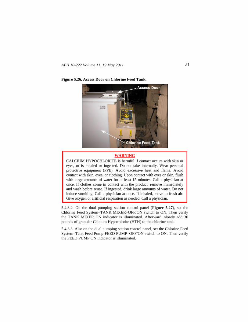
AFH 10-222 Volume 11, 19 May 2011 81
Figure 5.26. Access Door on Chlorine Feed Tank.
5.4.3.2. On the dual pumping station control panel (Figure 5.27), set the
Chlorine Feed System–TANK MIXER–OFF/ON switch to ON. Then verify
the TANK MIXER ON indicator is illuminated. Afterward, slowly add 30
pounds of granular Calcium Hypochlorite (HTH) to the chlorine tank.
5.4.3.3. Also on the dual pumping station control panel, set the Chlorine Feed
System–Tank Feed Pump-FEED PUMP–OFF/ON switch to ON. Then verify
the FEED PUMP ON indicator is illuminated.
WARNING
CALCIUM HYPOCHLORITE is harmful if contact occurs with skin or
eyes, or is inhaled or ingested. Do not take internally. Wear personal
protective equipment (PPE). Avoid excessive heat and flame. Avoid
contact with skin, eyes, or clothing. Upon contact with eyes or skin, flush
with large amounts of water for at least 15 minutes. Call a physician at
once. If clothes come in contact with the product, remove immediately
and wash before reuse. If ingested, drink large amounts of water. Do not
induce vomiting. Call a physician at once. If inhaled, move to fresh air.
Give oxygen or artificial respiration as needed. Call a physician.
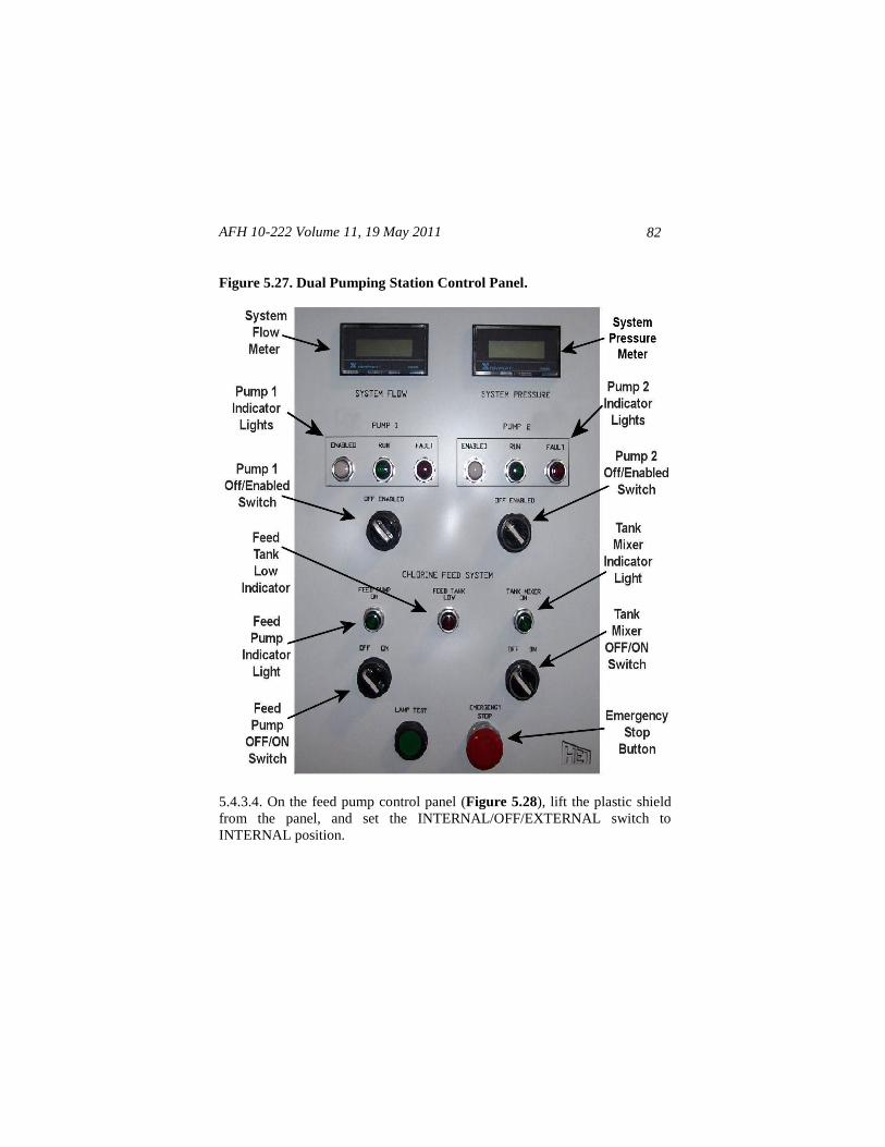
AFH 10-222 Volume 11, 19 May 2011
82
Figure 5.27. Dual Pumping Station Control Panel.
5.4.3.4. On the feed pump control panel (Figure 5.28), lift the plastic shield
from the panel, and set the INTERNAL/OFF/EXTERNAL switch to
INTERNAL position.
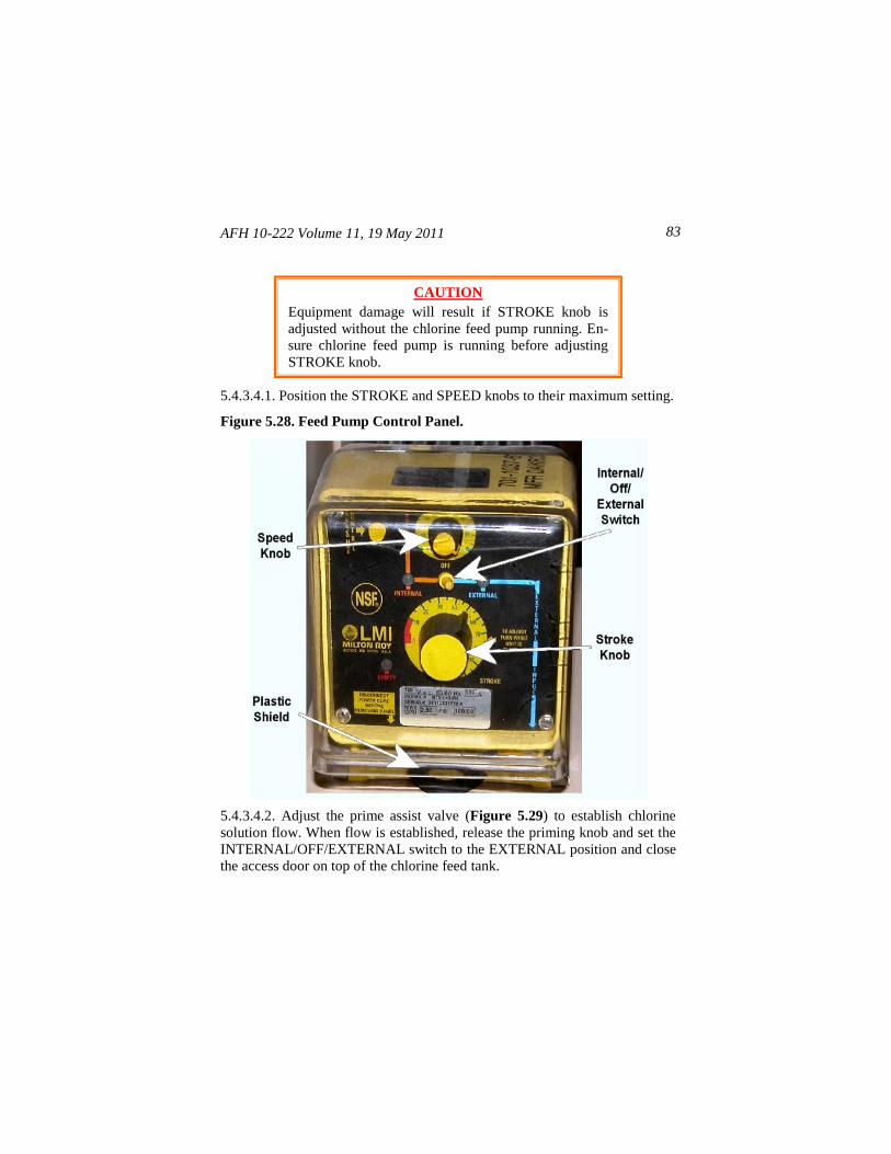
AFH 10-222 Volume 11, 19 May 2011 83
5.4.3.4.1. Position the STROKE and SPEED knobs to their maximum setting.
Figure 5.28. Feed Pump Control Panel.
5.4.3.4.2. Adjust the prime assist valve (Figure 5.29) to establish chlorine
solution flow. When flow is established, release the priming knob and set the
INTERNAL/OFF/EXTERNAL switch to the EXTERNAL position and close
the access door on top of the chlorine feed tank.
CAUTION
Equipment damage will result if STROKE knob is
adjusted without the chlorine feed pump running. En-
sure chlorine feed pump is running before adjusting
STROKE knob.
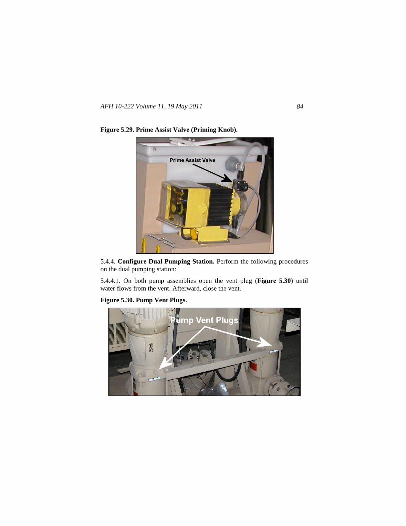
AFH 10-222 Volume 11, 19 May 2011
84
Figure 5.29. Prime Assist Valve (Priming Knob).
5.4.4. Configure Dual Pumping Station. Perform the following procedures
on the dual pumping station:
5.4.4.1. On both pump assemblies open the vent plug (Figure 5.30) until
water flows from the vent. Afterward, close the vent.
Figure 5.30. Pump Vent Plugs.
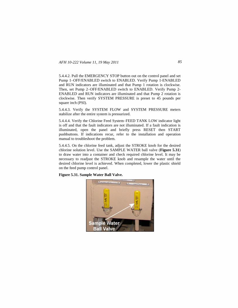
AFH 10-222 Volume 11, 19 May 2011 85
5.4.4.2. Pull the EMERGENCY STOP button out on the control panel and set
Pump 1–OFF/ENABLED switch to ENABLED. Verify Pump 1-ENABLED
and RUN indicators are illuminated and that Pump 1 rotation is clockwise.
Then, set Pump 2–OFF/ENABLED switch to ENABLED. Verify Pump 2-
ENABLED and RUN indicators are illuminated and that Pump 2 rotation is
clockwise. Then verify SYSTEM PRESSURE is preset to 45 pounds per
square inch (PSI).
5.4.4.3. Verify the SYSTEM FLOW and SYSTEM PRESSURE meters
stabilize after the entire system is pressurized.
5.4.4.4. Verify the Chlorine Feed System–FEED TANK LOW indicator light
is off and that the fault indicators are not illuminated. If a fault indication is
illuminated, open the panel and briefly press RESET then START
pushbuttons. If indications recur, refer to the installation and operation
manual to troubleshoot the problem.
5.4.4.5. On the chlorine feed tank, adjust the STROKE knob for the desired
chlorine solution level. Use the SAMPLE WATER ball valve (Figure 5.31)
to draw water into a container and check required chlorine level. It may be
necessary to readjust the STROKE knob and resample the water until the
desired chlorine level is achieved. When completed, lower the plastic shield
on the feed pump control panel.
Figure 5.31. Sample Water Ball Valve.
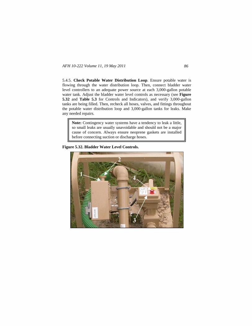
AFH 10-222 Volume 11, 19 May 2011
86
5.4.5. Check Potable Water Distribution Loop. Ensure potable water is
flowing through the water distribution loop. Then, connect bladder water
level controllers to an adequate power source at each 3,000-gallon potable
water tank. Adjust the bladder water level controls as necessary (see Figure
5.32 and Table 5.3 for Controls and Indicators), and verify 3,000-gallon
tanks are being filled. Then, recheck all hoses, valves, and fittings throughout
the potable water distribution loop and 3,000-gallon tanks for leaks. Make
any needed repairs.
Figure 5.32. Bladder Water Level Controls.
Note: Contingency water systems have a tendency to leak a little,
so small leaks are usually unavoidable and should not be a major
cause of concern. Always ensure neoprene gaskets are installed
before connecting suction or discharge hoses.
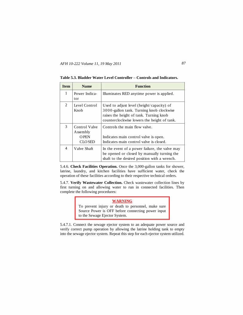
AFH 10-222 Volume 11, 19 May 2011 87
Table 5.3. Bladder Water Level Controller – Controls and Indicators.
Item Name Function
1 Power Indica-
tor
Illuminates RED anytime power is applied.
2 Level Control
Knob
Used to adjust level (height/ capacity) of
3 0 0 0 -gallon tank. Turning knob clockwise
raises the height of tank. Turning knob
counterclockwise lowers the height of tank.
3 Control Valve
Assembly
O PEN
CLO SED
Controls the main flow valve.
Indicates main control valve is open.
Indicates main control valve is closed.
4 Valve Shaft In the event of a power failure, the valve may
be opened or closed by manually turning the
shaft to the desired position with a wrench.
5.4.6. Check Facilities Operation. Once the 3,000-gallon tanks for shower,
latrine, laundry, and kitchen facilities have sufficient water, check the
operation of these facilities according to their respective technical orders.
5.4.7. Verify Wastewater Collection. Check wastewater collection lines by
first turning on and allowing water to run in connected facilities. Then
complete the following procedures:
5.4.7.1. Connect the sewage ejector system to an adequate power source and
verify correct pump operation by allowing the latrine holding tank to empty
into the sewage ejector system. Repeat this step for each ejector system utilized.
WARNING
To prevent injury or death to personnel, make sure
Source Power is OFF before connecting power input
to the Sewage Ejector System.
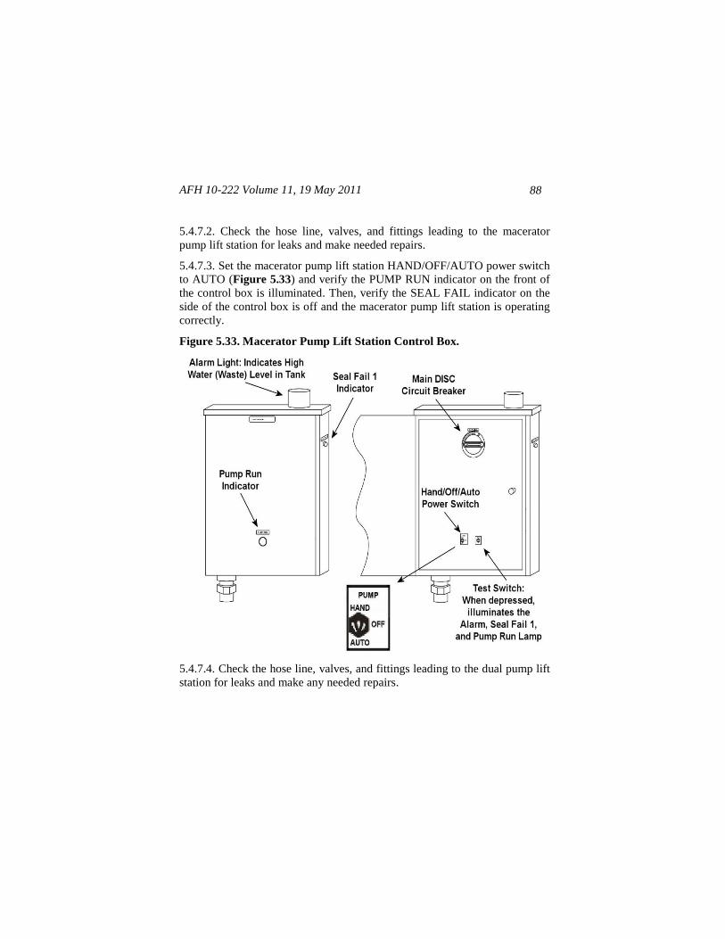
AFH 10-222 Volume 11, 19 May 2011
88
5.4.7.2. Check the hose line, valves, and fittings leading to the macerator
pump lift station for leaks and make needed repairs.
5.4.7.3. Set the macerator pump lift station HAND/OFF/AUTO power switch
to AUTO (Figure 5.33) and verify the PUMP RUN indicator on the front of
the control box is illuminated. Then, verify the SEAL FAIL indicator on the
side of the control box is off and the macerator pump lift station is operating
correctly.
Figure 5.33. Macerator Pump Lift Station Control Box.
5.4.7.4. Check the hose line, valves, and fittings leading to the dual pump lift
station for leaks and make any needed repairs.
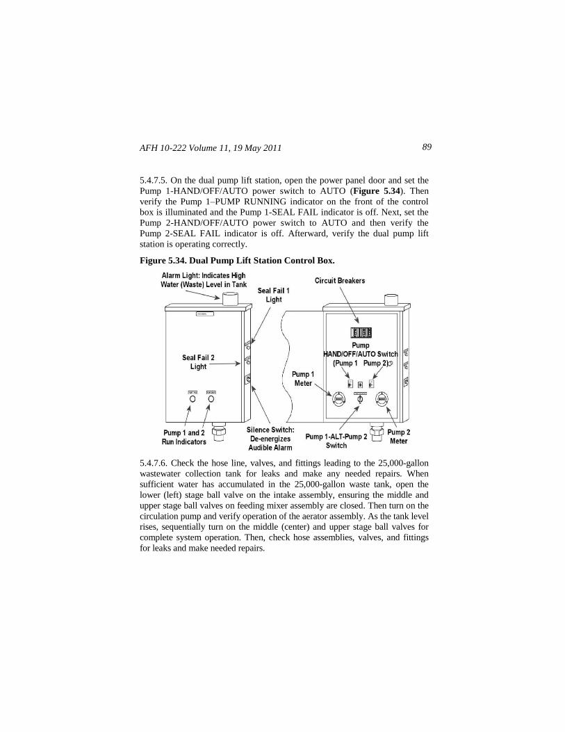
AFH 10-222 Volume 11, 19 May 2011 89
5.4.7.5. On the dual pump lift station, open the power panel door and set the
Pump 1-HAND/OFF/AUTO power switch to AUTO (Figure 5.34). Then
verify the Pump 1–PUMP RUNNING indicator on the front of the control
box is illuminated and the Pump 1-SEAL FAIL indicator is off. Next, set the
Pump 2-HAND/OFF/AUTO power switch to AUTO and then verify the
Pump 2-SEAL FAIL indicator is off. Afterward, verify the dual pump lift
station is operating correctly.
Figure 5.34. Dual Pump Lift Station Control Box.
5.4.7.6. Check the hose line, valves, and fittings leading to the 25,000-gallon
wastewater collection tank for leaks and make any needed repairs. When
sufficient water has accumulated in the 25,000-gallon waste tank, open the
lower (left) stage ball valve on the intake assembly, ensuring the middle and
upper stage ball valves on feeding mixer assembly are closed. Then turn on the
circulation pump and verify operation of the aerator assembly. As the tank level
rises, sequentially turn on the middle (center) and upper stage ball valves for
complete system operation. Then, check hose assemblies, valves, and fittings
for leaks and make needed repairs.
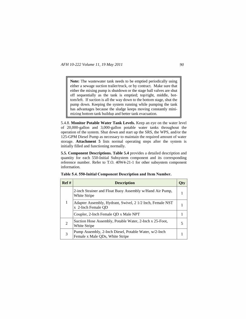
AFH 10-222 Volume 11, 19 May 2011
90
5.4.8. Monitor Potable Water Tank Levels. Keep an eye on the water level
of 20,000-gallon and 3,000-gallon potable water tanks throughout the
operation of the system. Shut down and start up the SRS, the WPS, and/or the
125-GPM Diesel Pump as necessary to maintain the required amount of water
storage. Attachment 5 lists normal operating steps after the system is
initially filled and functioning normally.
5.5. Component Descriptions. Table 5.4 provides a detailed description and
quantity for each 550-Initial Subsystem component and its corresponding
reference number. Refer to T.O. 40W4-21-1 for other subsystem component
information.
Table 5.4. 550-Initial Component Description and Item Number.
Ref # Description Qty
1
2-inch Strainer and Float Buoy Assembly w/Hand Air Pump,
White Stripe 1
Adapter Assembly, Hydrant, Swivel, 2 1/2 Inch, Female NST
x 2-Inch Female QD 1
Coupler, 2-Inch Female QD x Male NPT 1
2 Suction Hose Assembly, Potable Water, 2-Inch x 25-Foot,
White Stripe 5
3 Pump Assembly, 2-Inch Diesel, Potable Water, w/2-Inch
Female x Male QDs, White Stripe 1
Note: The wastewater tank needs to be emptied periodically using
either a sewage suction trailer/truck, or by contract. Make sure that
either the mixing pump is shutdown or the stage ball valves are shut
off sequentially as the tank is emptied; top/right, middle, bot-
tom/left. If suction is all the way down to the bottom stage, shut the
pump down. Keeping the system running while pumping the tank
has advantages because the sludge keeps moving constantly mini-
mizing bottom tank buildup and better tank evacuation.
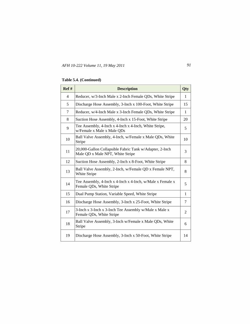
AFH 10-222 Volume 11, 19 May 2011 91
Table 5.4. (Continued)
Ref # Description Qty
4 Reducer, w/3-Inch Male x 2-Inch Female QDs, White Stripe 1
5 Discharge Hose Assembly, 3-Inch x 100-Foot, White Stripe 15
7 Reducer, w/4-Inch Male x 3-Inch Female QDs, White Stripe 1
8 Suction Hose Assembly, 4-Inch x 15-Foot, White Stripe 20
9 Tee Assembly, 4-Inch x 4-Inch x 4-Inch, White Stripe,
w/Female x Male x Male QDs 5
10 Ball Valve Assembly, 4-Inch, w/Female x Male QDs, White
Stripe 10
11 20,000-Gallon Collapsible Fabric Tank w/Adapter, 2-Inch
Male QD x Male NPT, White Stripe 3
12 Suction Hose Assembly, 2-Inch x 8-Foot, White Stripe 8
13 Ball Valve Assembly, 2-Inch, w/Female QD x Female NPT,
White Stripe 8
14 Tee Assembly, 4-Inch x 4-Inch x 4-Inch, w/Male x Female x
Female QDs, White Stripe 5
15 Dual Pump Station, Variable Speed, White Stripe 1
16 Discharge Hose Assembly, 3-Inch x 25-Foot, White Stripe 7
17 3-Inch x 3-Inch x 3-Inch Tee Assembly w/Male x Male x
Female QDs, White Stripe 2
18 Ball Valve Assembly, 3-Inch w/Female x Male QDs, White
Stripe 6
19 Discharge Hose Assembly, 3-Inch x 50-Foot, White Stripe 14
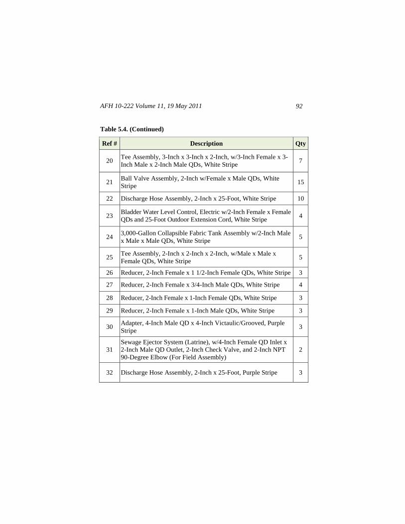
AFH 10-222 Volume 11, 19 May 2011
92
Table 5.4. (Continued)
Ref # Description Qty
20 Tee Assembly, 3-Inch x 3-Inch x 2-Inch, w/3-Inch Female x 3-
Inch Male x 2-Inch Male QDs, White Stripe 7
21 Ball Valve Assembly, 2-Inch w/Female x Male QDs, White
Stripe 15
22 Discharge Hose Assembly, 2-Inch x 25-Foot, White Stripe 10
23 Bladder Water Level Control, Electric w/2-Inch Female x Female
QDs and 25-Foot Outdoor Extension Cord, White Stripe 4
24 3,000-Gallon Collapsible Fabric Tank Assembly w/2-Inch Male
x Male x Male QDs, White Stripe 5
25 Tee Assembly, 2-Inch x 2-Inch x 2-Inch, w/Male x Male x
Female QDs, White Stripe 5
26 Reducer, 2-Inch Female x 1 1/2-Inch Female QDs, White Stripe 3
27 Reducer, 2-Inch Female x 3/4-Inch Male QDs, White Stripe 4
28 Reducer, 2-Inch Female x 1-Inch Female QDs, White Stripe 3
29 Reducer, 2-Inch Female x 1-Inch Male QDs, White Stripe 3
30 Adapter, 4-Inch Male QD x 4-Inch Victaulic/Grooved, Purple
Stripe 3
31
Sewage Ejector System (Latrine), w/4-Inch Female QD Inlet x
2-Inch Male QD Outlet, 2-Inch Check Valve, and 2-Inch NPT
90-Degree Elbow (For Field Assembly)
2
32 Discharge Hose Assembly, 2-Inch x 25-Foot, Purple Stripe 3
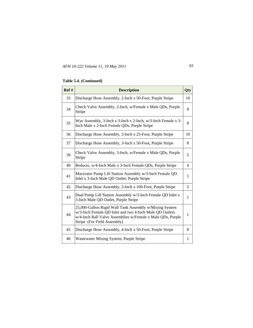
AFH 10-222 Volume 11, 19 May 2011 93
Table 5.4. (Continued)
Ref # Description Qty
33 Discharge Hose Assembly, 2-Inch x 50-Foot, Purple Stripe 10
34 Check Valve Assembly, 2-Inch, w/Female x Male QDs, Purple
Stripe 8
35 Wye Assembly, 3-Inch x 3-Inch x 2-Inch, w/3-Inch Female x 3-
Inch Male x 2-Inch Female QDs, Purple Stripe 8
36 Discharge Hose Assembly, 3-Inch x 25-Foot, Purple Stripe 10
37 Discharge Hose Assembly, 3-Inch x 50-Foot, Purple Stripe 8
39 Check Valve Assembly, 3-Inch, w/Female x Male QDs, Purple
Stripe 5
40 Reducer, w/4-Inch Male x 3-Inch Female QDs, Purple Stripe 4
41 Macerator Pump Lift Station Assembly w/3-Inch Female QD
Inlet x 3-Inch Male QD Outlet, Purple Stripe 1
42 Discharge Hose Assembly, 3-Inch x 100-Foot, Purple Stripe 5
43 Dual Pump Lift Station Assembly w/3-Inch Female QD Inlet x
3-Inch Male QD Outlet, Purple Stripe 1
44
25,000-Gallon Rigid Wall Tank Assembly w/Mixing System
w/3-Inch Female QD Inlet and two 4-Inch Male QD Outlets
w/4-Inch Ball Valve Assemblies w/Female x Male QDs, Purple
Stripe (For Field Assembly)
1
45 Discharge Hose Assembly, 4-Inch x 50-Foot, Purple Stripe 8
46 Wastewater Mixing System, Purple Stripe 1
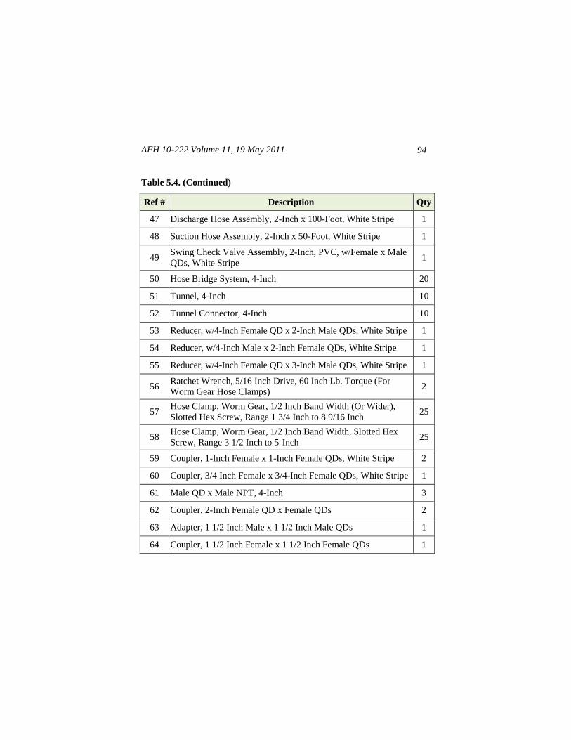
AFH 10-222 Volume 11, 19 May 2011
94
Table 5.4. (Continued)
Ref # Description Qty
47 Discharge Hose Assembly, 2-Inch x 100-Foot, White Stripe 1
48 Suction Hose Assembly, 2-Inch x 50-Foot, White Stripe 1
49 Swing Check Valve Assembly, 2-Inch, PVC, w/Female x Male
QDs, White Stripe 1
50 Hose Bridge System, 4-Inch 20
51 Tunnel, 4-Inch 10
52 Tunnel Connector, 4-Inch 10
53 Reducer, w/4-Inch Female QD x 2-Inch Male QDs, White Stripe 1
54 Reducer, w/4-Inch Male x 2-Inch Female QDs, White Stripe 1
55 Reducer, w/4-Inch Female QD x 3-Inch Male QDs, White Stripe 1
56 Ratchet Wrench, 5/16 Inch Drive, 60 Inch Lb. Torque (For
Worm Gear Hose Clamps) 2
57 Hose Clamp, Worm Gear, 1/2 Inch Band Width (Or Wider),
Slotted Hex Screw, Range 1 3/4 Inch to 8 9/16 Inch 25
58 Hose Clamp, Worm Gear, 1/2 Inch Band Width, Slotted Hex
Screw, Range 3 1/2 Inch to 5-Inch 25
59 Coupler, 1-Inch Female x 1-Inch Female QDs, White Stripe 2
60 Coupler, 3/4 Inch Female x 3/4-Inch Female QDs, White Stripe 1
61 Male QD x Male NPT, 4-Inch 3
62 Coupler, 2-Inch Female QD x Female QDs 2
63 Adapter, 1 1/2 Inch Male x 1 1/2 Inch Male QDs 1
64 Coupler, 1 1/2 Inch Female x 1 1/2 Inch Female QDs 1
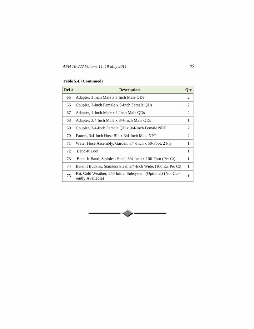
AFH 10-222 Volume 11, 19 May 2011 95
Table 5.4. (Continued)
Ref # Description Qty
65 Adapter, 3 Inch Male x 3 Inch Male QDs 2
66 Coupler, 3-Inch Female x 3-Inch Female QDs 2
67 Adapter, 1-Inch Male x 1-Inch Male QDs 2
68 Adapter, 3/4 Inch Male x 3/4-Inch Male QDs 1
69 Coupler, 3/4-Inch Female QD x 3/4-Inch Female NPT 2
70 Faucet, 3/4-Inch Hose Bib x 3/4-Inch Male NPT 2
71 Water Hose Assembly, Garden, 3/4-Inch x 50-Foot, 2 Ply 1
72 Band-It Tool 1
73 Band-It Band, Stainless Steel, 3/4-Inch x 100-Foot (Per Ct) 1
74 Band It Buckles, Stainless Steel, 3/4-Inch Wide, (100 Ea. Per Ct) 1
75 Kit, Cold Weather, 550 Initial Subsystem (Optional) (Not Cur-
rently Available) 1
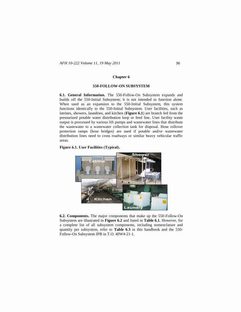
AFH 10-222 Volume 11, 19 May 2011
96
Chapter 6
550-FOLLOW-ON SUBSYSTEM
6.1. General Information. The 550-Follow-On Subsystem expands and
builds off the 550-Initial Subsystem; it is not intended to function alone.
When used as an expansion to the 550-Initial Subsystem, this system
functions identically to the 550-Initial Subsystem. User facilities, such as
latrines, showers, laundries, and kitchen (Figure 6.1) are branch fed from the
pressurized potable water distribution loop or feed line. User facility waste
output is processed by various lift pumps and wastewater lines that distribute
the wastewater to a wastewater collection tank for disposal. Hose rollover
protection ramps (hose bridges) are used if potable and/or wastewater
distribution lines need to cross roadways or similar heavy vehicular traffic
areas.
Figure 6.1. User Facilities (Typical).
6.2. Components. The major components that make up the 550-Follow-On
Subsystem are illustrated in Figure 6.2 and listed in Table 6.1. However, for
a complete list of all subsystem components, including nomenclature and
quantity per subsystem, refer to Table 6.3 in this handbook and the 550-
Follow-On Subsystem IPB in T.O. 40W4-21-1.
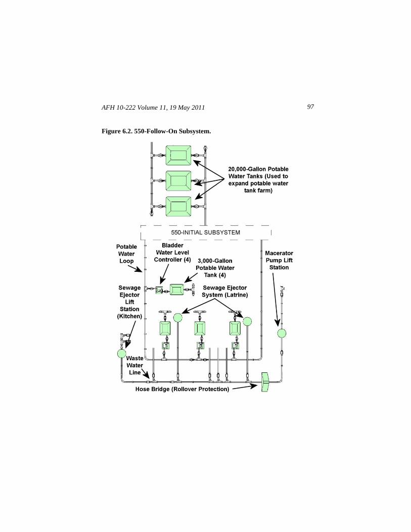
AFH 10-222 Volume 11, 19 May 2011 97
Figure 6.2. 550-Follow-On Subsystem.
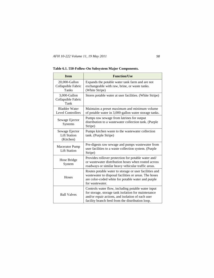
AFH 10-222 Volume 11, 19 May 2011
98
Table 6.1. 550-Follow-On Subsystem Major Components.
Item Function/Use
20,000-Gallon
Collapsible Fabric
Tanks
Expands the potable water tank farm and are not
exchangeable with raw, brine, or waste tanks.
(White Stripe)
3,000-Gallon
Collapsible Fabric
Tank
Stores potable water at user facilities. (White Stripe)
Bladder Water
Level Controllers
Maintains a preset maximum and minimum volume
of potable water in 3,000-gallon water storage tanks.
Sewage Ejector
Systems
Pumps raw sewage from latrines for output
distribution to a wastewater collection tank. (Purple
Stripe)
Sewage Ejector
Lift Station
(Kitchen)
Pumps kitchen waste to the wastewater collection
tank. (Purple Stripe)
Macerator Pump
Lift Station
Pre-digests raw sewage and pumps wastewater from
user facilities to a waste collection system. (Purple
Stripe)
Hose Bridge
System
Provides rollover protection for potable water and/
or wastewater distribution hoses when routed across
roadways or similar heavy vehicular traffic areas.
Hoses
Routes potable water to storage or user facilities and
wastewater to disposal facilities or areas. The hoses
are color-coded white for potable water and purple
for wastewater.
Ball Valves
Controls water flow, including potable water input
for storage, storage tank isolation for maintenance
and/or repair actions, and isolation of each user
facility branch feed from the distribution loop.
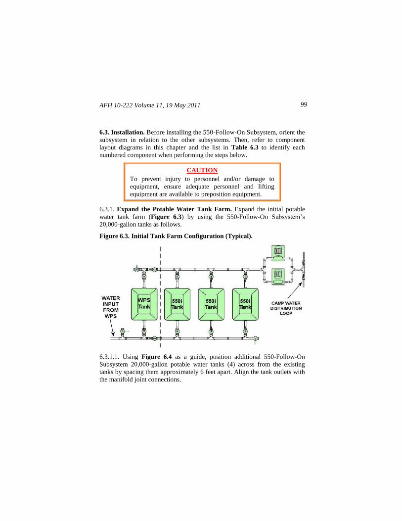
AFH 10-222 Volume 11, 19 May 2011 99
6.3. Installation. Before installing the 550-Follow-On Subsystem, orient the
subsystem in relation to the other subsystems. Then, refer to component
layout diagrams in this chapter and the list in Table 6.3 to identify each
numbered component when performing the steps below.
6.3.1. Expand the Potable Water Tank Farm. Expand the initial potable
water tank farm (Figure 6.3) by using the 550-Follow-On Subsystem’s
20,000-gallon tanks as follows.
Figure 6.3. Initial Tank Farm Configuration (Typical).
6.3.1.1. Using Figure 6.4 as a guide, position additional 550-Follow-On
Subsystem 20,000-gallon potable water tanks (4) across from the existing
tanks by spacing them approximately 6 feet apart. Align the tank outlets with
the manifold joint connections.
CAUTION
To prevent injury to personnel and/or damage to
equipment, ensure adequate personnel and lifting
equipment are available to preposition equipment.
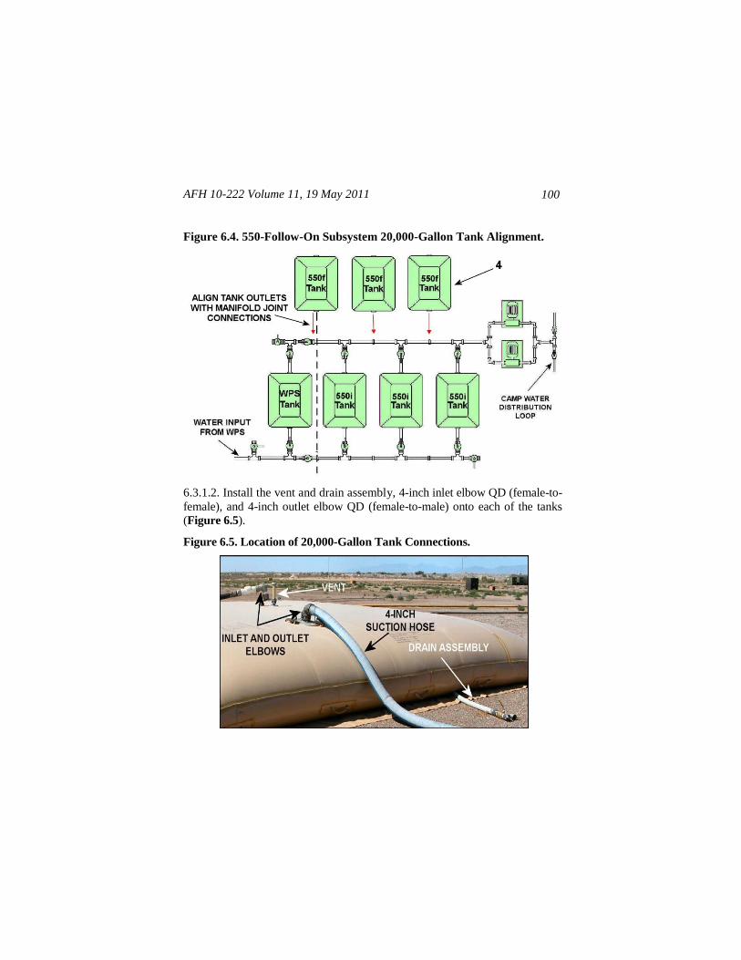
AFH 10-222 Volume 11, 19 May 2011
100
Figure 6.4. 550-Follow-On Subsystem 20,000-Gallon Tank Alignment.
6.3.1.2. Install the vent and drain assembly, 4-inch inlet elbow QD (female-to-
female), and 4-inch outlet elbow QD (female-to-male) onto each of the tanks
(Figure 6.5).
Figure 6.5. Location of 20,000-Gallon Tank Connections.
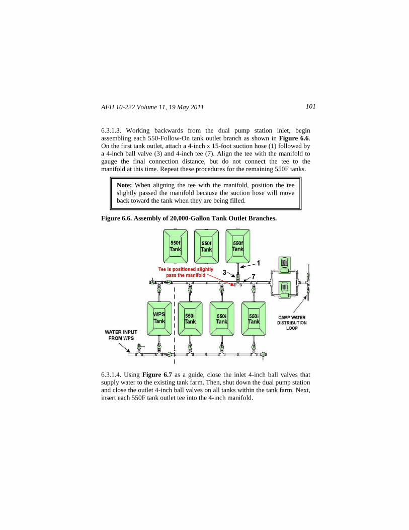
AFH 10-222 Volume 11, 19 May 2011 101
6.3.1.3. Working backwards from the dual pump station inlet, begin
assembling each 550-Follow-On tank outlet branch as shown in Figure 6.6.
On the first tank outlet, attach a 4-inch x 15-foot suction hose (1) followed by
a 4-inch ball valve (3) and 4-inch tee (7). Align the tee with the manifold to
gauge the final connection distance, but do not connect the tee to the
manifold at this time. Repeat these procedures for the remaining 550F tanks.
Figure 6.6. Assembly of 20,000-Gallon Tank Outlet Branches.
6.3.1.4. Using Figure 6.7 as a guide, close the inlet 4-inch ball valves that
supply water to the existing tank farm. Then, shut down the dual pump station
and close the outlet 4-inch ball valves on all tanks within the tank farm. Next,
insert each 550F tank outlet tee into the 4-inch manifold.
Note: When aligning the tee with the manifold, position the tee
slightly passed the manifold because the suction hose will move
back toward the tank when they are being filled.
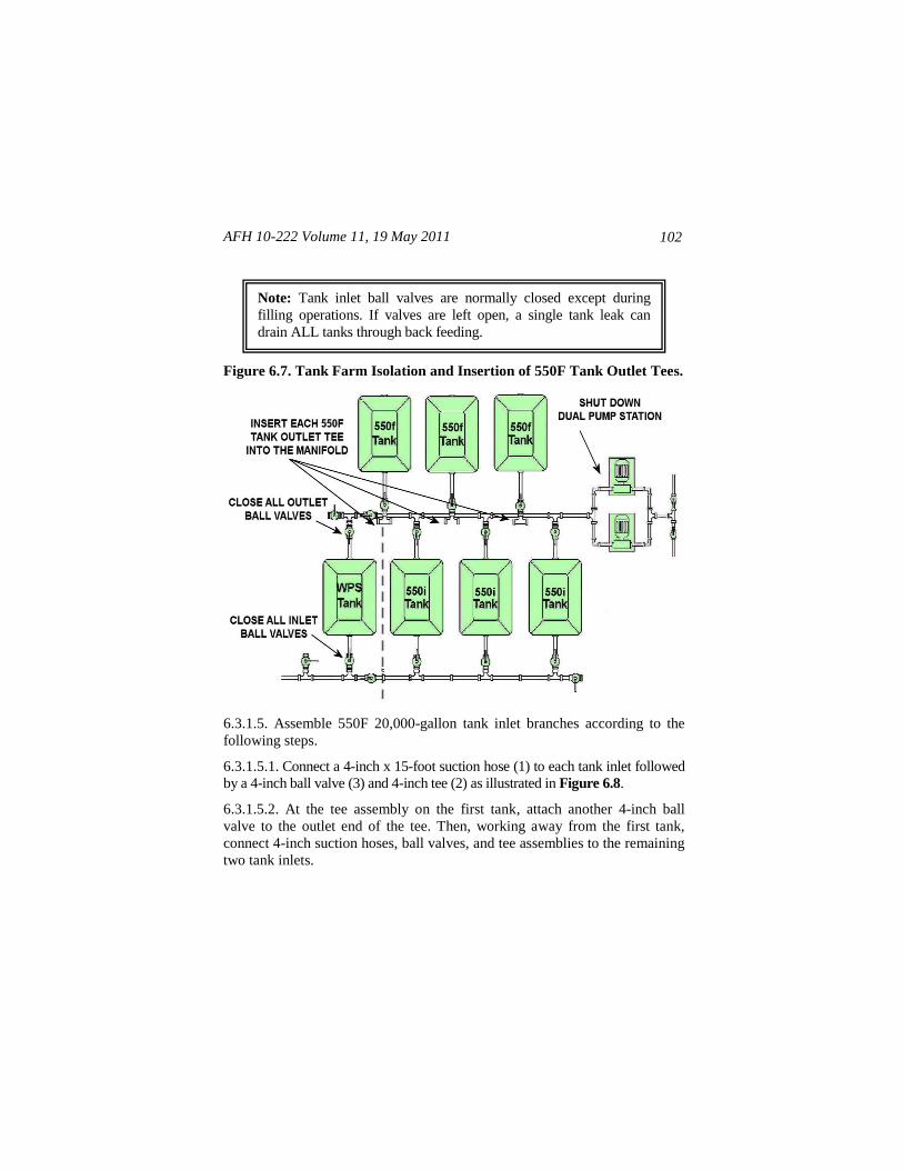
AFH 10-222 Volume 11, 19 May 2011
102
Figure 6.7. Tank Farm Isolation and Insertion of 550F Tank Outlet Tees.
6.3.1.5. Assemble 550F 20,000-gallon tank inlet branches according to the
following steps.
6.3.1.5.1. Connect a 4-inch x 15-foot suction hose (1) to each tank inlet followed
by a 4-inch ball valve (3) and 4-inch tee (2) as illustrated in Figure 6.8.
6.3.1.5.2. At the tee assembly on the first tank, attach another 4-inch ball
valve to the outlet end of the tee. Then, working away from the first tank,
connect 4-inch suction hoses, ball valves, and tee assemblies to the remaining
two tank inlets.
Note: Tank inlet ball valves are normally closed except during
filling operations. If valves are left open, a single tank leak can
drain ALL tanks through back feeding.
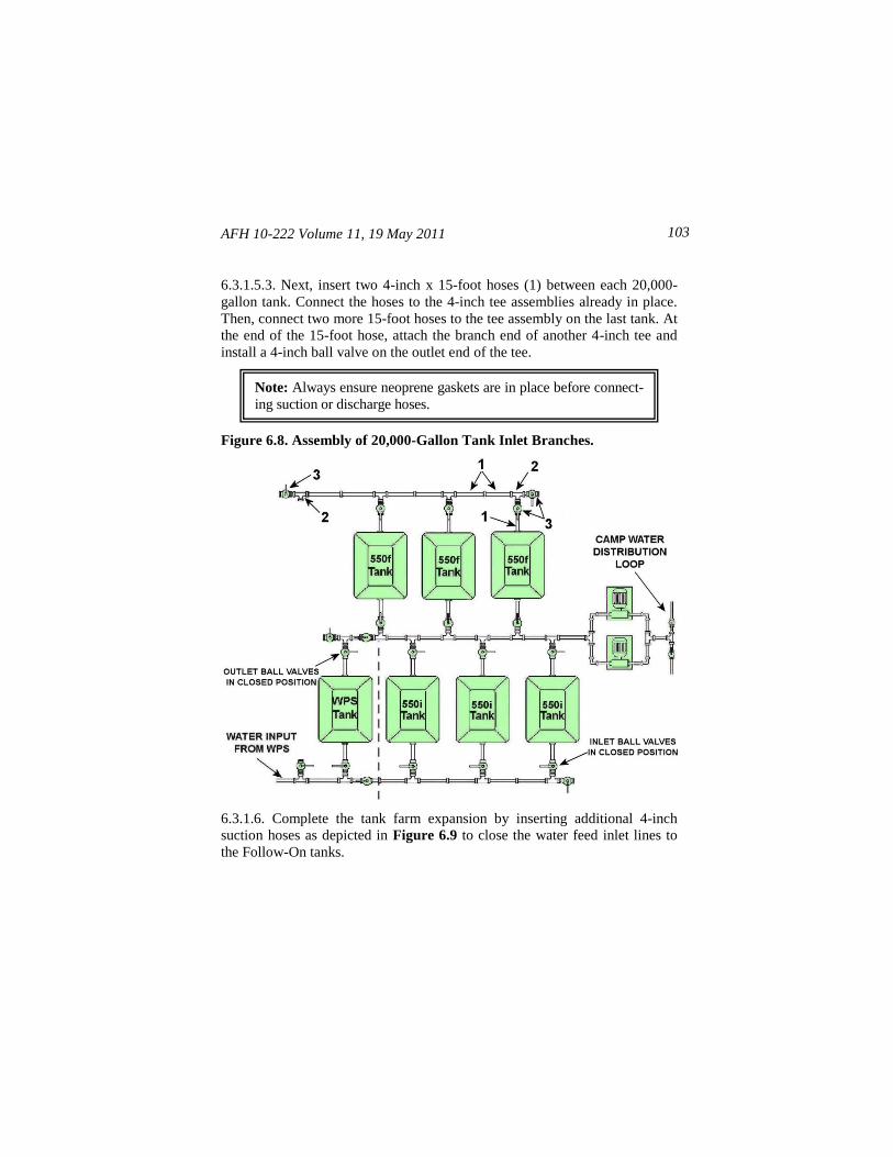
AFH 10-222 Volume 11, 19 May 2011 103
6.3.1.5.3. Next, insert two 4-inch x 15-foot hoses (1) between each 20,000-
gallon tank. Connect the hoses to the 4-inch tee assemblies already in place.
Then, connect two more 15-foot hoses to the tee assembly on the last tank. At
the end of the 15-foot hose, attach the branch end of another 4-inch tee and
install a 4-inch ball valve on the outlet end of the tee.
Figure 6.8. Assembly of 20,000-Gallon Tank Inlet Branches.
6.3.1.6. Complete the tank farm expansion by inserting additional 4-inch
suction hoses as depicted in Figure 6.9 to close the water feed inlet lines to
the Follow-On tanks.
Note: Always ensure neoprene gaskets are in place before connect-
ing suction or discharge hoses.
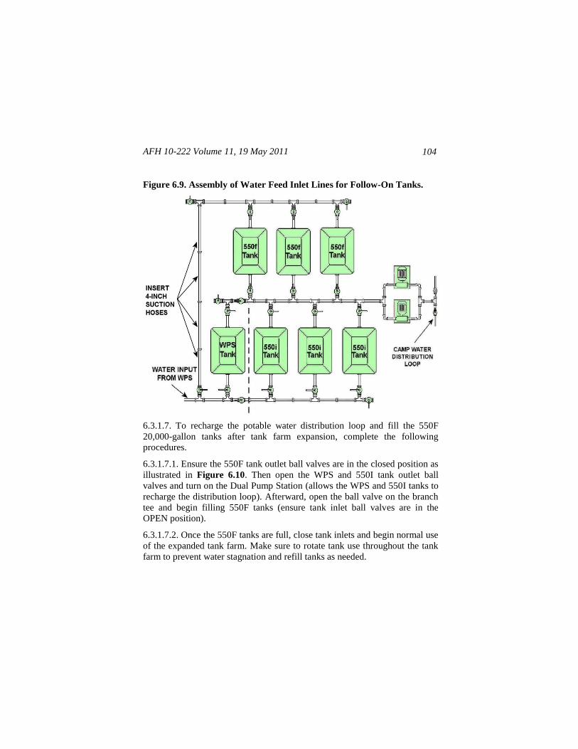
AFH 10-222 Volume 11, 19 May 2011
104
Figure 6.9. Assembly of Water Feed Inlet Lines for Follow-On Tanks.
6.3.1.7. To recharge the potable water distribution loop and fill the 550F
20,000-gallon tanks after tank farm expansion, complete the following
procedures.
6.3.1.7.1. Ensure the 550F tank outlet ball valves are in the closed position as
illustrated in Figure 6.10. Then open the WPS and 550I tank outlet ball
valves and turn on the Dual Pump Station (allows the WPS and 550I tanks to
recharge the distribution loop). Afterward, open the ball valve on the branch
tee and begin filling 550F tanks (ensure tank inlet ball valves are in the
OPEN position).
6.3.1.7.2. Once the 550F tanks are full, close tank inlets and begin normal use
of the expanded tank farm. Make sure to rotate tank use throughout the tank
farm to prevent water stagnation and refill tanks as needed.
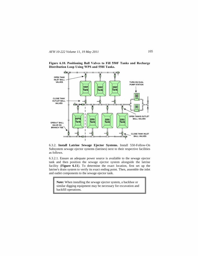
AFH 10-222 Volume 11, 19 May 2011 105
Figure 6.10. Positioning Ball Valves to Fill 550F Tanks and Recharge
Distribution Loop Using WPS and 550I Tanks.
6.3.2. Install Latrine Sewage Ejector Systems. Install 550-Follow-On
Subsystem sewage ejector systems (latrines) next to their respective facilities
as follows.
6.3.2.1. Ensure an adequate power source is available to the sewage ejector
tank and then position the sewage ejector system alongside the latrine
facility (Figure 6.11). To determine the exact location, first set up the
latrine's drain system to verify its exact ending point. Then, assemble the inlet
and outlet components to the sewage ejector tank.
Note: When installing the sewage ejector system, a backhoe or
similar digging equipment may be necessary for excavation and
backfill operations.
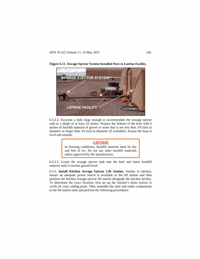
AFH 10-222 Volume 11, 19 May 2011
106
Figure 6.11. Sewage Ejector System Installed Next to Latrine Facility.
6.3.2.2. Excavate a hole large enough to accommodate the sewage ejector
tank to a depth of at least 24 inches. Prepare the bottom of the hole with 6
inches of backfill material of gravel or stone that is not less than 3/8 inch in
diameter or larger than 3/4 inch in diameter (if available). Ensure the base is
level and smooth.
6.3.2.3. Lower the sewage ejector tank into the hole and insert backfill
material until it reaches ground level.
6.3.3. Install Kitchen Sewage Ejector Lift Station. Similar to latrines,
ensure an adequate power source is available to the lift station and then
position the kitchen sewage ejector lift station alongside the kitchen facility.
To determine the exact location, first set up the kitchen’s drain system to
verify its exact ending point. Then assemble the inlet and outlet components
to the lift station tank and perform the following procedures:
CAUTION
In freezing conditions, backfill material must be dry
and free of ice. Do not use other backfill materials
unless approved by the manufacturer.
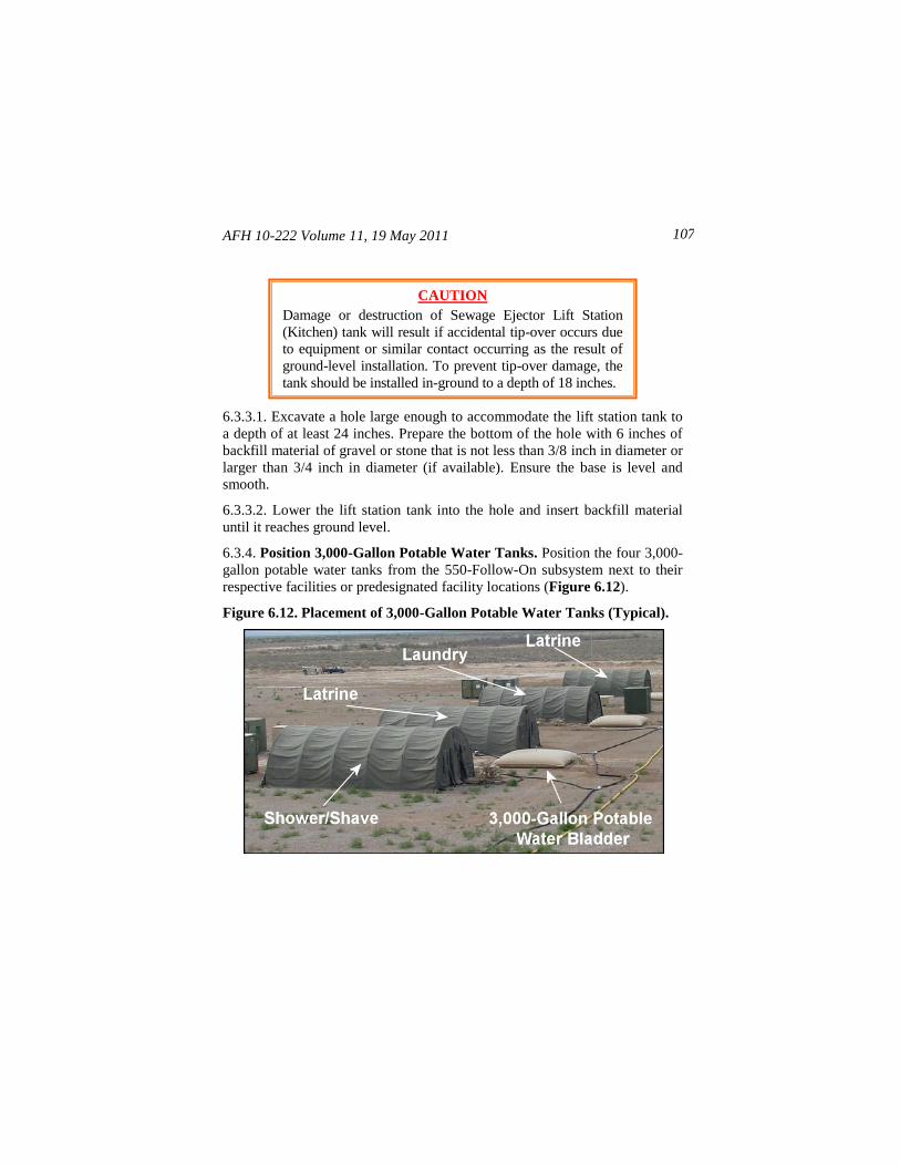
AFH 10-222 Volume 11, 19 May 2011 107
6.3.3.1. Excavate a hole large enough to accommodate the lift station tank to
a depth of at least 24 inches. Prepare the bottom of the hole with 6 inches of
backfill material of gravel or stone that is not less than 3/8 inch in diameter or
larger than 3/4 inch in diameter (if available). Ensure the base is level and
smooth.
6.3.3.2. Lower the lift station tank into the hole and insert backfill material
until it reaches ground level.
6.3.4. Position 3,000-Gallon Potable Water Tanks. Position the four 3,000-
gallon potable water tanks from the 550-Follow-On subsystem next to their
respective facilities or predesignated facility locations (Figure 6.12).
Figure 6.12. Placement of 3,000-Gallon Potable Water Tanks (Typical).
CAUTION
Damage or destruction of Sewage Ejector Lift Station
(Kitchen) tank will result if accidental tip-over occurs due
to equipment or similar contact occurring as the result of
ground-level installation. To prevent tip-over damage, the
tank should be installed in-ground to a depth of 18 inches.
AFH 10-222 Volume 11, 19 May 2011
108
6.3.4.1. Position one 3,000-gallon potable water tank approximately 25 feet
away from the kitchen’s water connection.
6.3.4.2. Position the next two 3,000-gallon potable water tanks approximately
25 feet away and centered between each of the two shower/shave and latrine
facilities to where each tank will feed one shower/shave and one latrine facility.
6.3.4.3. Position the last 3,000-gallon potable water tank directly behind and
approximately 25 feet away from the laundry facility.
6.3.4.4. Finally, connect vent and drain assemblies to all 3,000-gallon tanks.
6.3.5. Expand Potable Water Distribution Loop and Facility Connections.
Using the potable water components in the 550-Follow-On Subsystem,
expand the 550-Initial Subsystem potable water distribution loop and facility
connections according to requirements at the deployment location. Figure
6.13 provides a basic example of a distribution loop expansion.
6.3.5.1. Beginning at the outlet of the dual pump station’s 3-inch branch tee,
begin expanding the potable water distribution loop by connecting the 3-inch
x 100-foot discharge hoses (9) to the 3-inch ball valve on the branch tee.
6.3.5.2. Using 3-inch discharge hoses in lengths of 100 feet (9), 50 feet (8),
and 25 feet (11), lay out the potable water distribution loop toward the water-
using facilities. If possible, route the hose away from high traffic areas. It may
be preferable to use the 3-inch x 100-foot hoses first, and then the 50-foot and
25-foot hoses where needed to properly position the hose so it is centered and
within 20 to 25 feet of the inlet side of facility 3,000-gallon tanks.
Note: Always ensure neoprene gaskets are in place before connect-
ing suction or discharge hoses.
Note: All water tanks (bladders or vessels) that are inserted into the
water distribution loop or downstream but connected to the Dual
Pump Station MUST have a bladder water level controller or be
manually filled and isolated with a valve inserted on the inlet side
of the bladder/vessel.
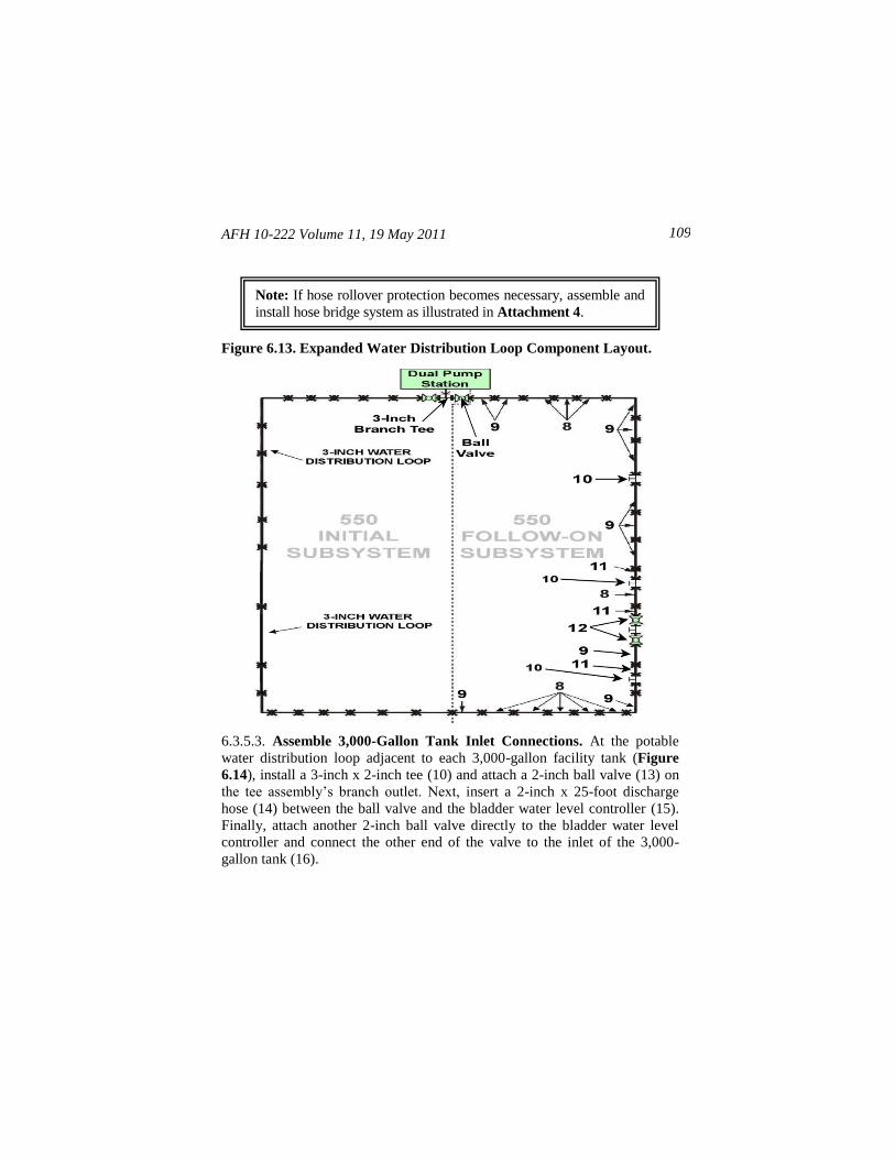
AFH 10-222 Volume 11, 19 May 2011 109
Figure 6.13. Expanded Water Distribution Loop Component Layout.
6.3.5.3. Assemble 3,000-Gallon Tank Inlet Connections. At the potable
water distribution loop adjacent to each 3,000-gallon facility tank (Figure
6.14), install a 3-inch x 2-inch tee (10) and attach a 2-inch ball valve (13) on
the tee assembly’s branch outlet. Next, insert a 2-inch x 25-foot discharge
hose (14) between the ball valve and the bladder water level controller (15).
Finally, attach another 2-inch ball valve directly to the bladder water level
controller and connect the other end of the valve to the inlet of the 3,000-
gallon tank (16).
Note: If hose rollover protection becomes necessary, assemble and
install hose bridge system as illustrated in Attachment 4.
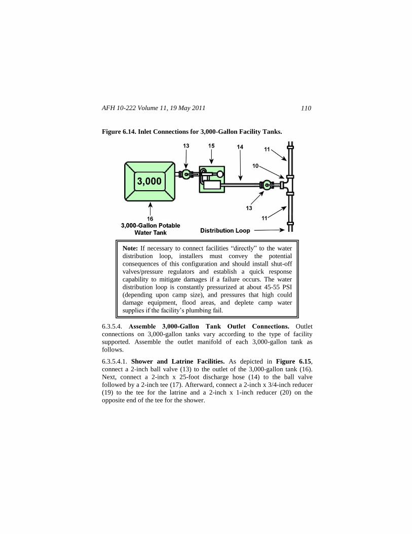
AFH 10-222 Volume 11, 19 May 2011
110
Figure 6.14. Inlet Connections for 3,000-Gallon Facility Tanks.
6.3.5.4. Assemble 3,000-Gallon Tank Outlet Connections. Outlet
connections on 3,000-gallon tanks vary according to the type of facility
supported. Assemble the outlet manifold of each 3,000-gallon tank as
follows.
6.3.5.4.1. Shower and Latrine Facilities. As depicted in Figure 6.15,
connect a 2-inch ball valve (13) to the outlet of the 3,000-gallon tank (16).
Next, connect a 2-inch x 25-foot discharge hose (14) to the ball valve
followed by a 2-inch tee (17). Afterward, connect a 2-inch x 3/4-inch reducer
(19) to the tee for the latrine and a 2-inch x 1-inch reducer (20) on the
opposite end of the tee for the shower.
Note: If necessary to connect facilities ―directly‖ to the water
distribution loop, installers must convey the potential
consequences of this configuration and should install shut-off
valves/pressure regulators and establish a quick response
capability to mitigate damages if a failure occurs. The water
distribution loop is constantly pressurized at about 45-55 PSI
(depending upon camp size), and pressures that high could
damage equipment, flood areas, and deplete camp water
supplies if the facility’s plumbing fail.
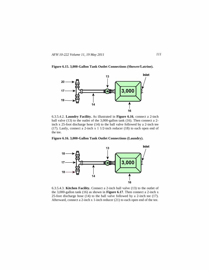
AFH 10-222 Volume 11, 19 May 2011 111
Figure 6.15. 3,000-Gallon Tank Outlet Connections (Shower/Latrine).
6.3.5.4.2. Laundry Facility. As illustrated in Figure 6.16, connect a 2-inch
ball valve (13) to the outlet of the 3,000-gallon tank (16). Then connect a 2-
inch x 25-foot discharge hose (14) to the ball valve followed by a 2-inch tee
(17). Lastly, connect a 2-inch x 1 1/2-inch reducer (18) to each open end of
the tee.
Figure 6.16. 3,000-Gallon Tank Outlet Connections (Laundry).
6.3.5.4.3. Kitchen Facility. Connect a 2-inch ball valve (13) to the outlet of
the 3,000-gallon tank (16) as shown in Figure 6.17. Then connect a 2-inch x
25-foot discharge hose (14) to the ball valve followed by a 2-inch tee (17).
Afterward, connect a 2-inch x 1-inch reducer (21) to each open end of the tee.
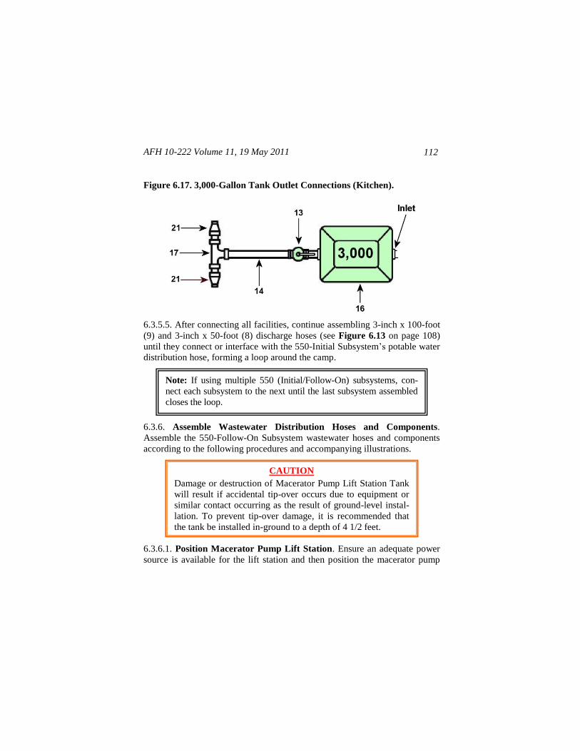
AFH 10-222 Volume 11, 19 May 2011
112
Figure 6.17. 3,000-Gallon Tank Outlet Connections (Kitchen).
6.3.5.5. After connecting all facilities, continue assembling 3-inch x 100-foot
(9) and 3-inch x 50-foot (8) discharge hoses (see Figure 6.13 on page 108)
until they connect or interface with the 550-Initial Subsystem’s potable water
distribution hose, forming a loop around the camp.
6.3.6. Assemble Wastewater Distribution Hoses and Components.
Assemble the 550-Follow-On Subsystem wastewater hoses and components
according to the following procedures and accompanying illustrations.
6.3.6.1. Position Macerator Pump Lift Station. Ensure an adequate power
source is available for the lift station and then position the macerator pump
CAUTION
Damage or destruction of Macerator Pump Lift Station Tank
will result if accidental tip-over occurs due to equipment or
similar contact occurring as the result of ground-level instal-
lation. To prevent tip-over damage, it is recommended that
the tank be installed in-ground to a depth of 4 1/2 feet.
Note: If using multiple 550 (Initial/Follow-On) subsystems, con-
nect each subsystem to the next until the last subsystem assembled
closes the loop.
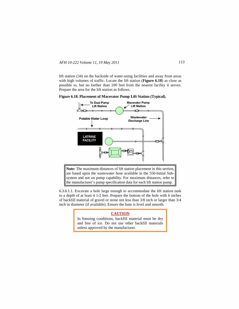
AFH 10-222 Volume 11, 19 May 2011 113
lift station (34) on the backside of water-using facilities and away from areas
with high volumes of traffic. Locate the lift station (Figure 6.18) as close as
possible to, but no farther than 100 feet from the nearest facility it serves.
Prepare the area for the lift station as follows.
Figure 6.18. Placement of Macerator Pump Lift Station (Typical).
6.3.6.1.1. Excavate a hole large enough to accommodate the lift station tank
to a depth of at least 4 1/2 feet. Prepare the bottom of the hole with 6 inches
of backfill material of gravel or stone not less than 3/8 inch or larger than 3/4
inch in diameter (if available). Ensure the base is level and smooth.
CAUTION
In freezing conditions, backfill material must be dry
and free of ice. Do not use other backfill materials
unless approved by the manufacturer.
Note: The maximum distances of lift station placement in this section,
are based upon the wastewater hose available in the 550-Initial Sub-
system and not on pump capability. For maximum distances, refer to
the manufacturer’s pump specification data for each lift station pump.
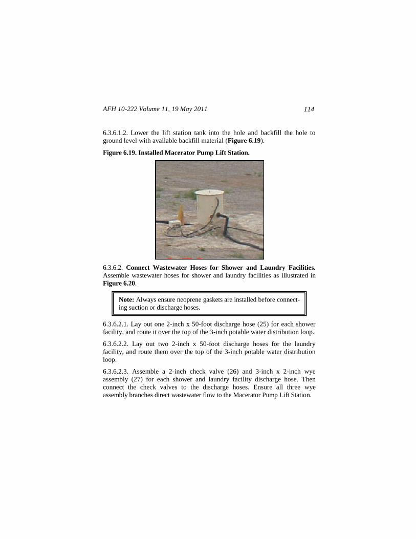
AFH 10-222 Volume 11, 19 May 2011
114
6.3.6.1.2. Lower the lift station tank into the hole and backfill the hole to
ground level with available backfill material (Figure 6.19).
Figure 6.19. Installed Macerator Pump Lift Station.
6.3.6.2. Connect Wastewater Hoses for Shower and Laundry Facilities.
Assemble wastewater hoses for shower and laundry facilities as illustrated in
Figure 6.20.
6.3.6.2.1. Lay out one 2-inch x 50-foot discharge hose (25) for each shower
facility, and route it over the top of the 3-inch potable water distribution loop.
6.3.6.2.2. Lay out two 2-inch x 50-foot discharge hoses for the laundry
facility, and route them over the top of the 3-inch potable water distribution
loop.
6.3.6.2.3. Assemble a 2-inch check valve (26) and 3-inch x 2-inch wye
assembly (27) for each shower and laundry facility discharge hose. Then
connect the check valves to the discharge hoses. Ensure all three wye
assembly branches direct wastewater flow to the Macerator Pump Lift Station.
Note: Always ensure neoprene gaskets are installed before connect-
ing suction or discharge hoses.
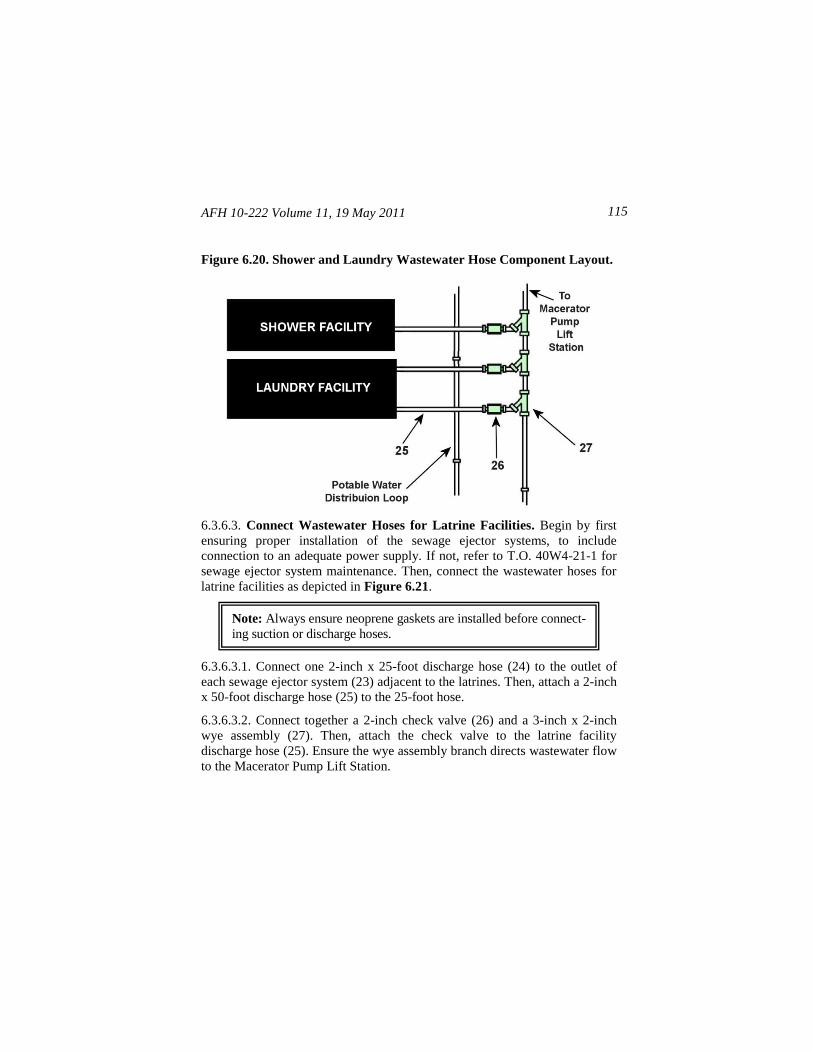
AFH 10-222 Volume 11, 19 May 2011 115
Figure 6.20. Shower and Laundry Wastewater Hose Component Layout.
6.3.6.3. Connect Wastewater Hoses for Latrine Facilities. Begin by first
ensuring proper installation of the sewage ejector systems, to include
connection to an adequate power supply. If not, refer to T.O. 40W4-21-1 for
sewage ejector system maintenance. Then, connect the wastewater hoses for
latrine facilities as depicted in Figure 6.21.
6.3.6.3.1. Connect one 2-inch x 25-foot discharge hose (24) to the outlet of
each sewage ejector system (23) adjacent to the latrines. Then, attach a 2-inch
x 50-foot discharge hose (25) to the 25-foot hose.
6.3.6.3.2. Connect together a 2-inch check valve (26) and a 3-inch x 2-inch
wye assembly (27). Then, attach the check valve to the latrine facility
discharge hose (25). Ensure the wye assembly branch directs wastewater flow
to the Macerator Pump Lift Station.
Note: Always ensure neoprene gaskets are installed before connect-
ing suction or discharge hoses.
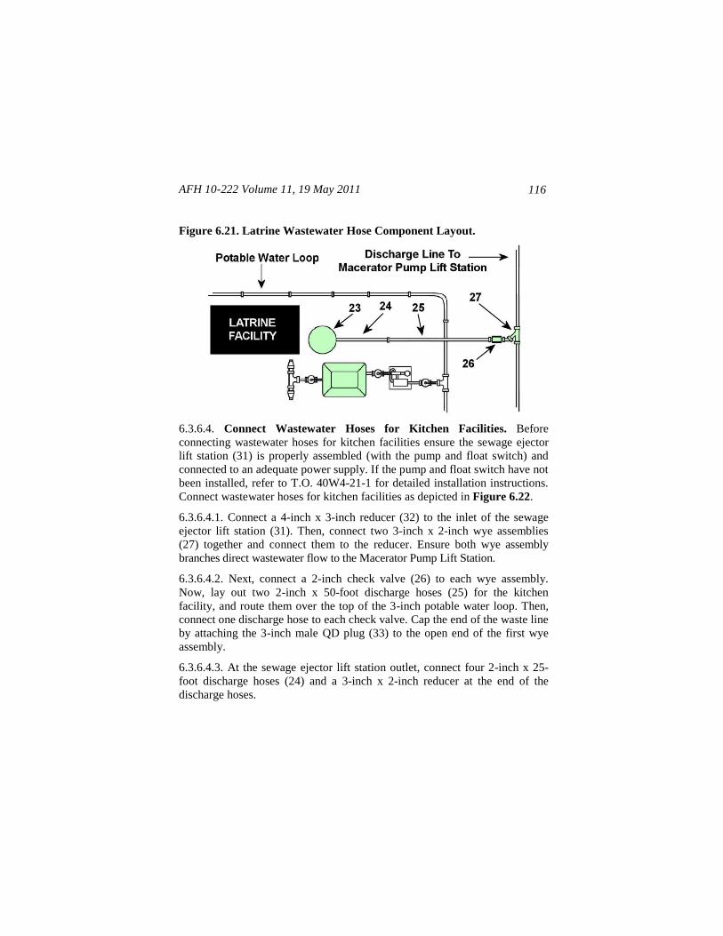
AFH 10-222 Volume 11, 19 May 2011
116
Figure 6.21. Latrine Wastewater Hose Component Layout.
6.3.6.4. Connect Wastewater Hoses for Kitchen Facilities. Before
connecting wastewater hoses for kitchen facilities ensure the sewage ejector
lift station (31) is properly assembled (with the pump and float switch) and
connected to an adequate power supply. If the pump and float switch have not
been installed, refer to T.O. 40W4-21-1 for detailed installation instructions.
Connect wastewater hoses for kitchen facilities as depicted in Figure 6.22.
6.3.6.4.1. Connect a 4-inch x 3-inch reducer (32) to the inlet of the sewage
ejector lift station (31). Then, connect two 3-inch x 2-inch wye assemblies
(27) together and connect them to the reducer. Ensure both wye assembly
branches direct wastewater flow to the Macerator Pump Lift Station.
6.3.6.4.2. Next, connect a 2-inch check valve (26) to each wye assembly.
Now, lay out two 2-inch x 50-foot discharge hoses (25) for the kitchen
facility, and route them over the top of the 3-inch potable water loop. Then,
connect one discharge hose to each check valve. Cap the end of the waste line
by attaching the 3-inch male QD plug (33) to the open end of the first wye
assembly.
6.3.6.4.3. At the sewage ejector lift station outlet, connect four 2-inch x 25-
foot discharge hoses (24) and a 3-inch x 2-inch reducer at the end of the
discharge hoses.
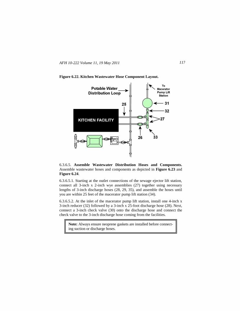
AFH 10-222 Volume 11, 19 May 2011 117
Figure 6.22. Kitchen Wastewater Hose Component Layout.
6.3.6.5. Assemble Wastewater Distribution Hoses and Components.
Assemble wastewater hoses and components as depicted in Figure 6.23 and
Figure 6.24.
6.3.6.5.1. Starting at the outlet connections of the sewage ejector lift station,
connect all 3-inch x 2-inch wye assemblies (27) together using necessary
lengths of 3-inch discharge hoses (28, 29, 35), and assemble the hoses until
you are within 25 feet of the macerator pump lift station (34).
6.3.6.5.2. At the inlet of the macerator pump lift station, install one 4-inch x
3-inch reducer (32) followed by a 3-inch x 25-foot discharge hose (28). Next,
connect a 3-inch check valve (30) onto the discharge hose and connect the
check valve to the 3-inch discharge hose coming from the facilities.
Note: Always ensure neoprene gaskets are installed before connect-
ing suction or discharge hoses.
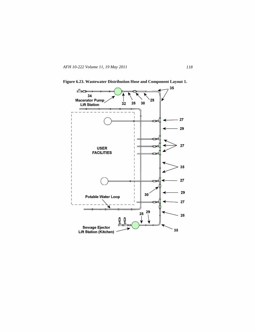
AFH 10-222 Volume 11, 19 May 2011
118
Figure 6.23. Wastewater Distribution Hose and Component Layout 1.
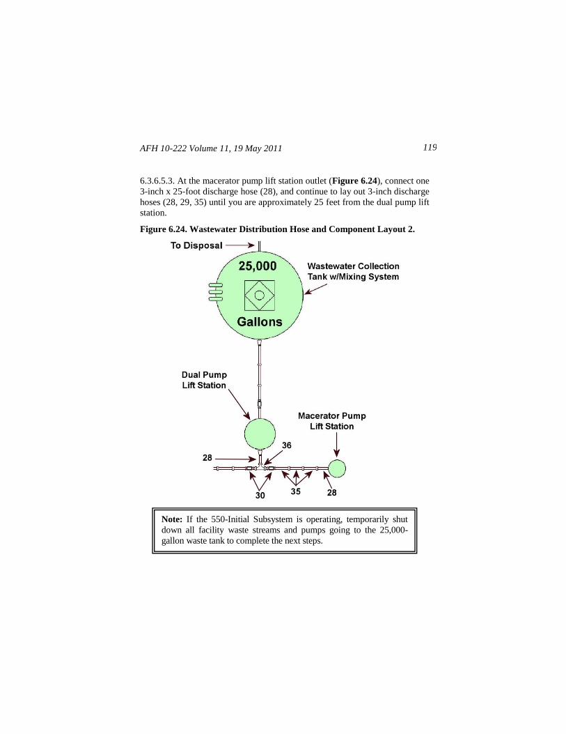
AFH 10-222 Volume 11, 19 May 2011 119
6.3.6.5.3. At the macerator pump lift station outlet (Figure 6.24), connect one
3-inch x 25-foot discharge hose (28), and continue to lay out 3-inch discharge
hoses (28, 29, 35) until you are approximately 25 feet from the dual pump lift
station.
Figure 6.24. Wastewater Distribution Hose and Component Layout 2.
Note: If the 550-Initial Subsystem is operating, temporarily shut
down all facility waste streams and pumps going to the 25,000-
gallon waste tank to complete the next steps.
AFH 10-222 Volume 11, 19 May 2011
120
6.3.6.5.4. At the dual pump lift station, insert the branch end of the 3-inch tee
(36) into the inlet side of the 3-inch x 25-foot discharge hose (28) that was
already assembled to the dual pump lift station during 550-Initial Subsystem
installation.
6.3.6.5.5. Connect a 3-inch check valve (30) from the 550-Initial Subsystem
onto one end of the 3-inch tee. If not already preassembled during the initial
subsystem installation, connect another 3-inch check valve onto the other end
of the 3-inch tee. Now, complete the 550-Follow-On Subsystem wastewater
piping by connecting the 3-inch x 100-foot discharge hose (35) from the
macerator pump lift station to the 3-inch check valve.
6.3.6.5.6. If any of the subsystem plumbing is routed across roadways or
similar heavy vehicular traffic areas, use the hose bridge system to provide
hose rollover protection. Assemble the hose bridge system as illustrated in
Attachment 4. This completes basic installation of the 550-Follow-On
Subsystem.
6.4. Operation. The following procedures address basic steps to operate the
550-Follow-On Subsystem when integrated with the 550-Initial Subsystem. If
necessary, refer to basic layout diagrams presented throughout this chapter
for component identification.
6.4.1. Perform Subsystem Preoperational Checks. Before operating the
subsystem, complete preoperational checks outlined in Table 6.2.
WARNING
To prevent injury or death to personnel, make sure
Source Power is OFF before connecting power input
to the Macerator Pump Lift Station or Sewage Ejector
System.
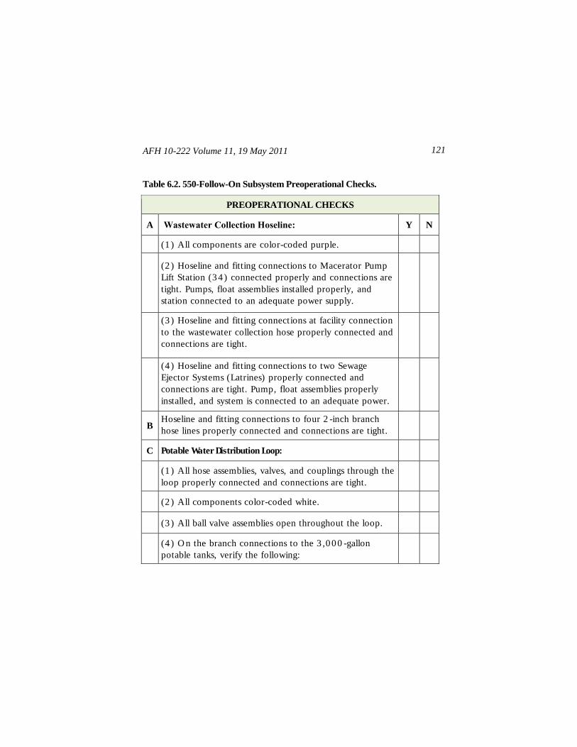
AFH 10-222 Volume 11, 19 May 2011 121
Table 6.2. 550-Follow-On Subsystem Preoperational Checks.
PREOPERATIONAL CHECKS
A Wastewater Collection Hoseline: Y N
(1 ) All components are color-coded purple.
(2 ) Hoseline and fitting connections to Macerator Pump
Lift Station (3 4 ) connected properly and connections are
tight. Pumps, float assemblies installed properly, and
station connected to an adequate power supply.
(3 ) Hoseline and fitting connections at facility connection
to the wastewater collection hose properly connected and
connections are tight.
(4 ) Hoseline and fitting connections to two Sewage
Ejector Systems (Latrines) properly connected and
connections are tight. Pump, float assemblies properly
installed, and system is connected to an adequate power.
B Hoseline and fitting connections to four 2 -inch branch
hose lines properly connected and connections are tight.
C Potable Water Distribution Loop:
(1 ) All hose assemblies, valves, and couplings through the
loop properly connected and connections are tight.
(2 ) All components color-coded white.
(3 ) All ball valve assemblies open throughout the loop.
(4 ) O n the branch connections to the 3 ,0 0 0 -gallon
potable tanks, verify the following:
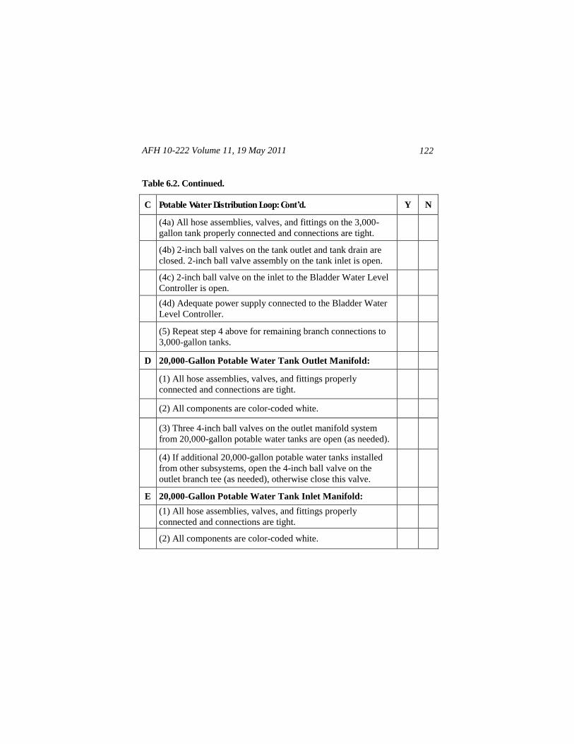
AFH 10-222 Volume 11, 19 May 2011
122
Table 6.2. Continued.
C Potable Water Distribution Loop: Cont’d. Y N
(4a) All hose assemblies, valves, and fittings on the 3,000-
gallon tank properly connected and connections are tight.
(4b) 2-inch ball valves on the tank outlet and tank drain are
closed. 2-inch ball valve assembly on the tank inlet is open.
(4c) 2-inch ball valve on the inlet to the Bladder Water Level
Controller is open.
(4d) Adequate power supply connected to the Bladder Water
Level Controller.
(5) Repeat step 4 above for remaining branch connections to
3,000-gallon tanks.
D 20,000-Gallon Potable Water Tank Outlet Manifold:
(1) All hose assemblies, valves, and fittings properly
connected and connections are tight.
(2) All components are color-coded white.
(3) Three 4-inch ball valves on the outlet manifold system
from 20,000-gallon potable water tanks are open (as needed).
(4) If additional 20,000-gallon potable water tanks installed
from other subsystems, open the 4-inch ball valve on the
outlet branch tee (as needed), otherwise close this valve.
E 20,000-Gallon Potable Water Tank Inlet Manifold:
(1) All hose assemblies, valves, and fittings properly
connected and connections are tight.
(2) All components are color-coded white.
AFH 10-222 Volume 11, 19 May 2011 123
6.4.2. Verify Potable Water Flow. Verify water is flowing in the 3-inch
potable water distribution loop. Ensure an adequate power source connection
to bladder water level controllers at each 3,000-gallon potable water tank.
Verify 3,000-gallon tanks are being filled. Recheck all hoses, valves, and
fittings throughout the 3-inch potable water loop and the 3,000-gallon tanks
for leaks. Make repairs as necessary.
6 .4 .3 . Check Facilities Operation. Once the 3,000-gallon tanks for shower,
latrine, laundry, and kitchen facilities have sufficient water, check the
operation of these facilities according to their respective technical orders.
6.4.4. Check Wastewater Collection. Check wastewater collection lines by
first turning on and allowing water to run in connected facilities. Then
complete the following procedures.
6.4.4.1. Connect the sewage ejector system (latrine) to an adequate power
source and verify correct pump operation by allowing the latrine holding tank
to empty into the sewage ejector system. Repeat this step for each sewage
ejector system (latrine) utilized.
6.4.4.2. Connect the sewage ejector system (kitchen) to an adequate power
source and verify correct pump operation by allowing the kitchen holding
tank to empty into the sewage ejector lift station (kitchen).
6.4.4.3. Check the hose line, valves, and fittings leading to the Macerator
Pump Lift Station for leaks and make needed repairs.
6.4.4.4. Set the macerator pump lift station HAND/OFF/AUTO power switch
(on the control box) to AUTO (see Figure 5.33 on page 87) and verify the
PUMP RUN indicator on the front of the control box is illuminated. Then,
verify the SEAL FAIL indicator on the side of the control box is OFF and the
macerator pump lift station is operating correctly.
WARNING
To prevent injury or death to personnel, make sure
Source Power is OFF before connecting power input
to the Sewage Ejector System (Latrine).
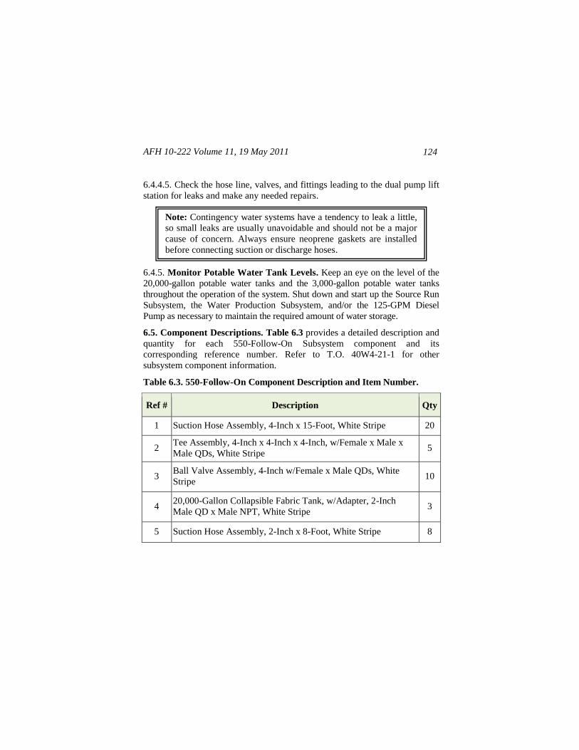
AFH 10-222 Volume 11, 19 May 2011
124
6.4.4.5. Check the hose line, valves, and fittings leading to the dual pump lift
station for leaks and make any needed repairs.
6.4.5. Monitor Potable Water Tank Levels. Keep an eye on the level of the
20,000-gallon potable water tanks and the 3,000-gallon potable water tanks
throughout the operation of the system. Shut down and start up the Source Run
Subsystem, the Water Production Subsystem, and/or the 125-GPM Diesel
Pump as necessary to maintain the required amount of water storage.
6.5. Component Descriptions. Table 6.3 provides a detailed description and
quantity for each 550-Follow-On Subsystem component and its
corresponding reference number. Refer to T.O. 40W4-21-1 for other
subsystem component information.
Table 6.3. 550-Follow-On Component Description and Item Number.
Ref # Description Qty
1 Suction Hose Assembly, 4-Inch x 15-Foot, White Stripe 20
2 Tee Assembly, 4-Inch x 4-Inch x 4-Inch, w/Female x Male x
Male QDs, White Stripe 5
3 Ball Valve Assembly, 4-Inch w/Female x Male QDs, White
Stripe 10
4 20,000-Gallon Collapsible Fabric Tank, w/Adapter, 2-Inch
Male QD x Male NPT, White Stripe 3
5 Suction Hose Assembly, 2-Inch x 8-Foot, White Stripe 8
Note: Contingency water systems have a tendency to leak a little,
so small leaks are usually unavoidable and should not be a major
cause of concern. Always ensure neoprene gaskets are installed
before connecting suction or discharge hoses.
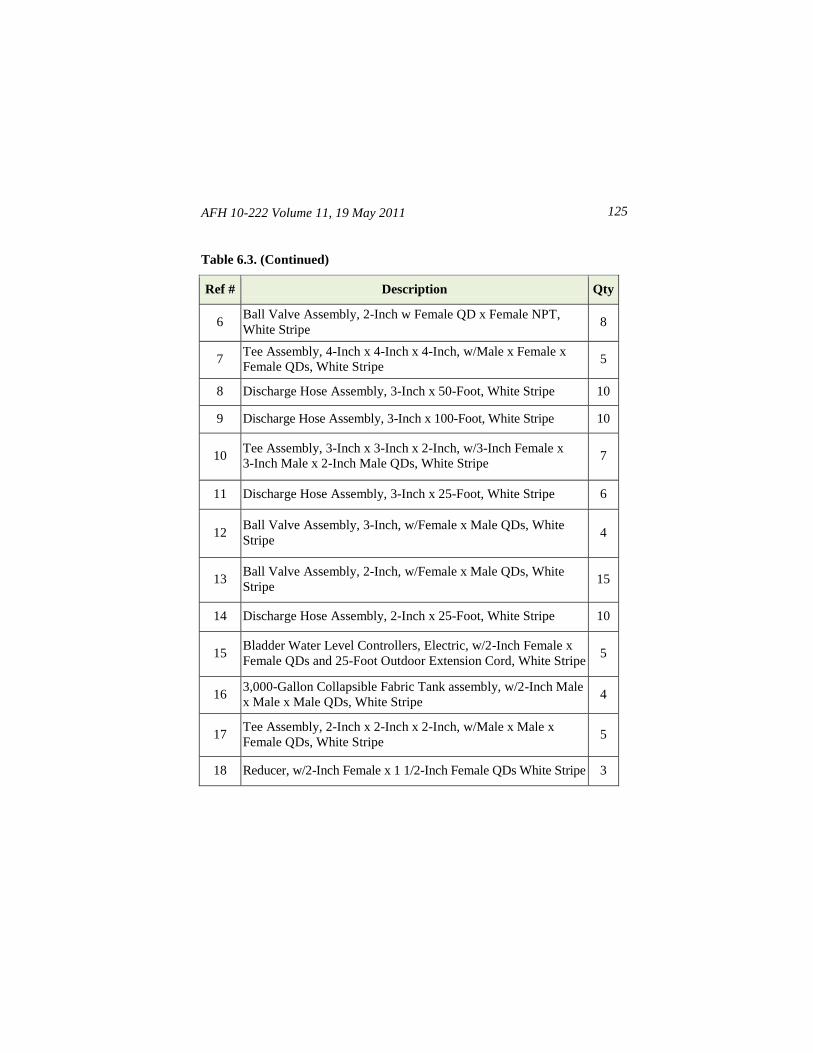
AFH 10-222 Volume 11, 19 May 2011 125
Table 6.3. (Continued)
Ref # Description Qty
6 Ball Valve Assembly, 2-Inch w Female QD x Female NPT,
White Stripe 8
7 Tee Assembly, 4-Inch x 4-Inch x 4-Inch, w/Male x Female x
Female QDs, White Stripe 5
8 Discharge Hose Assembly, 3-Inch x 50-Foot, White Stripe 10
9 Discharge Hose Assembly, 3-Inch x 100-Foot, White Stripe 10
10 Tee Assembly, 3-Inch x 3-Inch x 2-Inch, w/3-Inch Female x
3-Inch Male x 2-Inch Male QDs, White Stripe 7
11 Discharge Hose Assembly, 3-Inch x 25-Foot, White Stripe 6
12 Ball Valve Assembly, 3-Inch, w/Female x Male QDs, White
Stripe 4
13 Ball Valve Assembly, 2-Inch, w/Female x Male QDs, White
Stripe 15
14 Discharge Hose Assembly, 2-Inch x 25-Foot, White Stripe 10
15 Bladder Water Level Controllers, Electric, w/2-Inch Female x
Female QDs and 25-Foot Outdoor Extension Cord, White Stripe 5
16 3,000-Gallon Collapsible Fabric Tank assembly, w/2-Inch Male
x Male x Male QDs, White Stripe 4
17 Tee Assembly, 2-Inch x 2-Inch x 2-Inch, w/Male x Male x
Female QDs, White Stripe 5
18 Reducer, w/2-Inch Female x 1 1/2-Inch Female QDs White Stripe 3
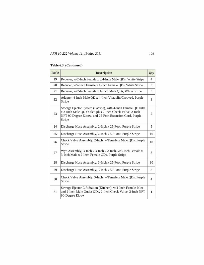
AFH 10-222 Volume 11, 19 May 2011
126
Table 6.3. (Continued)
Ref # Description Qty
19 Reducer, w/2-Inch Female x 3/4-Inch Male QDs, White Stripe 4
20 Reducer, w/2-Inch Female x 1-Inch Female QDs, White Stripe 3
21 Reducer, w/2-Inch Female x 1-Inch Male QDs, White Stripe 3
22 Adapter, 4-Inch Male QD x 4-Inch Victaulic/Grooved, Purple
Stripe 3
23
Sewage Ejector System (Latrine), with 4-inch Female QD Inlet
x 2-Inch Male QD Outlet, plus 2-Inch Check Valve, 2-Inch
NPT 90 Degree Elbow, and 25-Foot Extension Cord, Purple
Stripe
2
24 Discharge Hose Assembly, 2-Inch x 25-Foot, Purple Stripe 5
25 Discharge Hose Assembly, 2-Inch x 50-Foot, Purple Stripe 10
26 Check Valve Assembly, 2-Inch, w/Female x Male QDs, Purple
Stripe 10
27 Wye Assembly, 3-Inch x 3-Inch x 2-Inch, w/3-Inch Female x
3-Inch Male x 2-Inch Female QDs, Purple Stripe 8
28 Discharge Hose Assembly, 3-Inch x 25-Foot, Purple Stripe 10
29 Discharge Hose Assembly, 3-Inch x 50-Foot, Purple Stripe 8
30 Check Valve Assembly, 3-Inch, w/Female x Male QDs, Purple
Stripe 4
31
Sewage Ejector Lift Station (Kitchen), w/4-Inch Female Inlet
and 2-Inch Male Outlet QDs, 2-Inch Check Valve, 2-Inch NPT
90-Degree Elbow 1
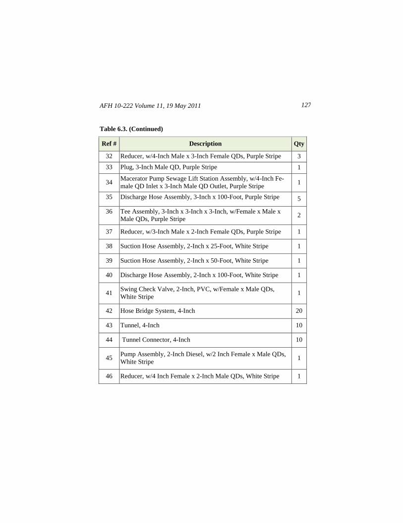
AFH 10-222 Volume 11, 19 May 2011 127
Table 6.3. (Continued)
Ref # Description Qty
32 Reducer, w/4-Inch Male x 3-Inch Female QDs, Purple Stripe 3
33 Plug, 3-Inch Male QD, Purple Stripe 1
34 Macerator Pump Sewage Lift Station Assembly, w/4-Inch Fe-
male QD Inlet x 3-Inch Male QD Outlet, Purple Stripe 1
35 Discharge Hose Assembly, 3-Inch x 100-Foot, Purple Stripe 5
36 Tee Assembly, 3-Inch x 3-Inch x 3-Inch, w/Female x Male x
Male QDs, Purple Stripe 2
37 Reducer, w/3-Inch Male x 2-Inch Female QDs, Purple Stripe 1
38 Suction Hose Assembly, 2-Inch x 25-Foot, White Stripe 1
39 Suction Hose Assembly, 2-Inch x 50-Foot, White Stripe 1
40 Discharge Hose Assembly, 2-Inch x 100-Foot, White Stripe 1
41 Swing Check Valve, 2-Inch, PVC, w/Female x Male QDs,
White Stripe 1
42 Hose Bridge System, 4-Inch 20
43 Tunnel, 4-Inch 10
44 Tunnel Connector, 4-Inch 10
45 Pump Assembly, 2-Inch Diesel, w/2 Inch Female x Male QDs,
White Stripe 1
46 Reducer, w/4 Inch Female x 2-Inch Male QDs, White Stripe 1
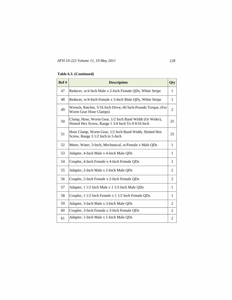
AFH 10-222 Volume 11, 19 May 2011
128
Table 6.3. (Continued)
Ref # Description Qty
47 Reducer, w/4 Inch Male x 2-Inch Female QDs, White Stripe 1
48 Reducer, w/4-Inch Female x 3-Inch Male QDs, White Stripe 1
49 Wrench, Ratchet, 5/16 Inch Drive, 60 Inch-Pounds Torque, (For
Worm Gear Hose Clamps) 2
50 Clamp, Hose, Worm Gear, 1/2 Inch Band Width (Or Wider),
Slotted Hex Screw, Range 1 3/4 Inch To 8 9/16 Inch 25
51 Hose Clamp, Worm Gear, 1/2 Inch Band Width, Slotted Hex
Screw, Range 3 1/2 Inch to 5-Inch 25
52 Meter, Water, 3-Inch, Mechanical, w/Female x Male QDs 1
53 Adapter, 4-Inch Male x 4-Inch Male QDs 1
54 Coupler, 4-Inch Female x 4-Inch Female QDs 1
55 Adapter, 2-Inch Male x 2-Inch Male QDs 2
56 Coupler, 2-Inch Female x 2-Inch Female QDs 2
57 Adapter, 1 1/2 Inch Male x 1 1/2-Inch Male QDs 1
58 Coupler, 1 1/2 Inch Female x 1 1/2 Inch Female QDs 1
59 Adapter, 3-Inch Male x 3-Inch Male QDs 2
60 Coupler, 3-Inch Female x 3-Inch Female QDs 2
61 Adapter, 1-Inch Male x 1-Inch Male QDs 2
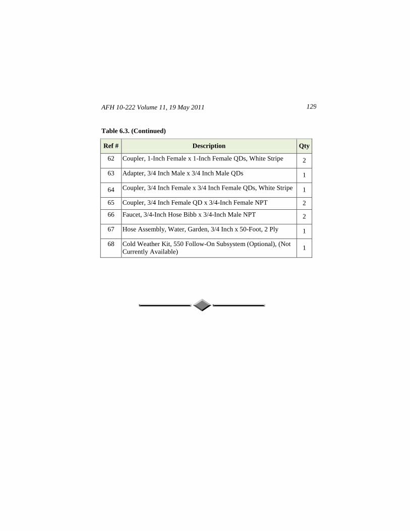
AFH 10-222 Volume 11, 19 May 2011 129
Table 6.3. (Continued)
Ref # Description Qty
62 Coupler, 1-Inch Female x 1-Inch Female QDs, White Stripe 2
63 Adapter, 3/4 Inch Male x 3/4 Inch Male QDs 1
64 Coupler, 3/4 Inch Female x 3/4 Inch Female QDs, White Stripe 1
65 Coupler, 3/4 Inch Female QD x 3/4-Inch Female NPT 2
66 Faucet, 3/4-Inch Hose Bibb x 3/4-Inch Male NPT 2
67 Hose Assembly, Water, Garden, 3/4 Inch x 50-Foot, 2 Ply 1
68 Cold Weather Kit, 550 Follow-On Subsystem (Optional), (Not
Currently Available) 1
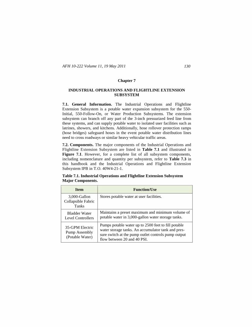
AFH 10-222 Volume 11, 19 May 2011
130
Chapter 7
INDUSTRIAL OPERATIONS AND FLIGHTLINE EXTENSION
SUBSYSTEM
7.1. General Information. The Industrial Operations and Flightline
Extension Subsystem is a potable water expansion subsystem for the 550-
Initial, 550-Follow-On, or Water Production Subsystems. The extension
subsystem can branch off any part of the 3-inch pressurized feed line from
these systems, and can supply potable water to isolated user facilities such as
latrines, showers, and kitchens. Additionally, hose rollover protection ramps
(hose bridges) safeguard hoses in the event potable water distribution lines
need to cross roadways or similar heavy vehicular traffic areas.
7.2. Components. The major components of the Industrial Operations and
Flightline Extension Subsystem are listed in Table 7.1 and illustrated in
Figure 7.1. However, for a complete list of all subsystem components,
including nomenclature and quantity per subsystem, refer to Table 7.3 in
this handbook and the Industrial Operations and Flightline Extension
Subsystem IPB in T.O. 40W4-21-1.
Table 7.1. Industrial Operations and Flightline Extension Subsystem
Major Components.
Item Function/Use
3,000-Gallon
Collapsible Fabric
Tanks
Stores potable water at user facilities.
Bladder Water
Level Controllers
Maintains a preset maximum and minimum volume of
potable water in 3,000-gallon water storage tanks.
35-GPM Electric
Pump Assembly
(Potable Water)
Pumps potable water up to 2500 feet to fill potable
water storage tanks. An accumulator tank and pres-
sure switch at the pump outlet controls pump output
flow between 20 and 40 PSI.
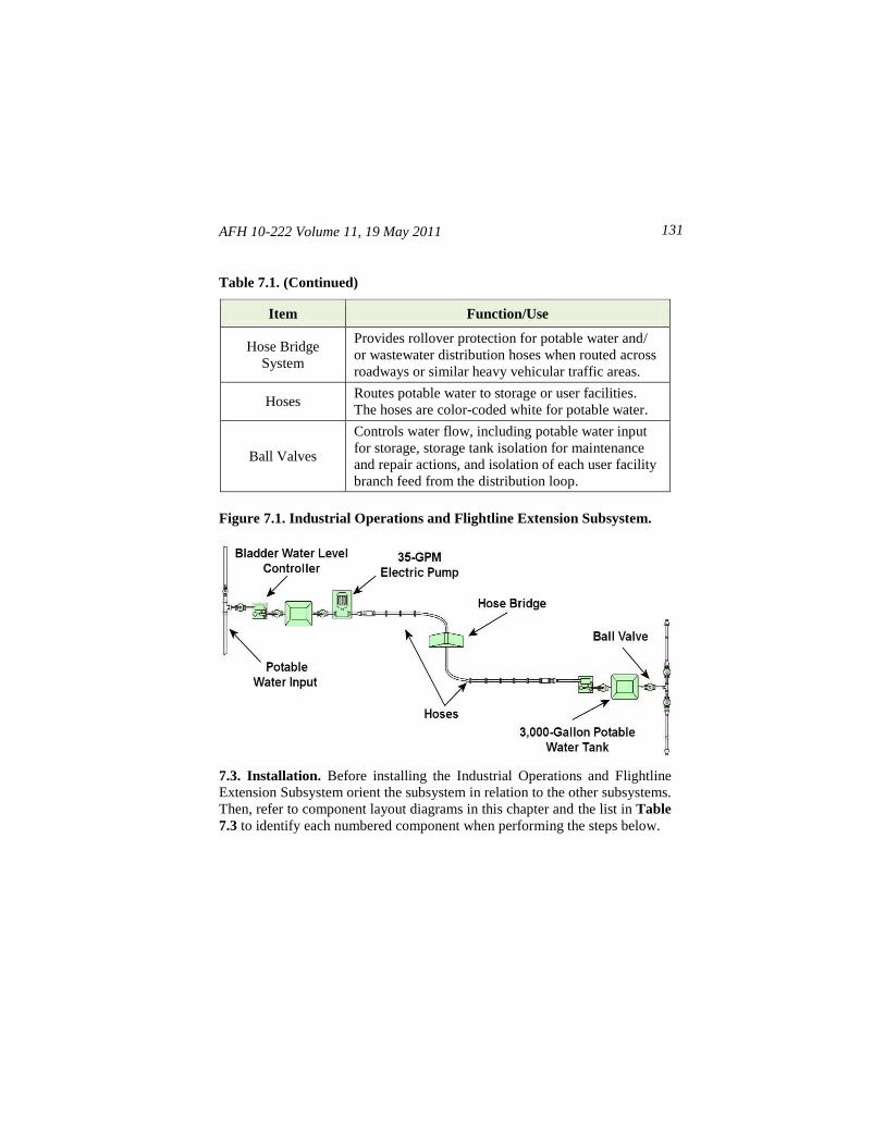
AFH 10-222 Volume 11, 19 May 2011 131
Table 7.1. (Continued)
Item Function/Use
Hose Bridge
System
Provides rollover protection for potable water and/
or wastewater distribution hoses when routed across
roadways or similar heavy vehicular traffic areas.
Hoses Routes potable water to storage or user facilities.
The hoses are color-coded white for potable water.
Ball Valves
Controls water flow, including potable water input
for storage, storage tank isolation for maintenance
and repair actions, and isolation of each user facility
branch feed from the distribution loop.
Figure 7.1. Industrial Operations and Flightline Extension Subsystem.
7.3. Installation. Before installing the Industrial Operations and Flightline
Extension Subsystem orient the subsystem in relation to the other subsystems.
Then, refer to component layout diagrams in this chapter and the list in Table
7.3 to identify each numbered component when performing the steps below.
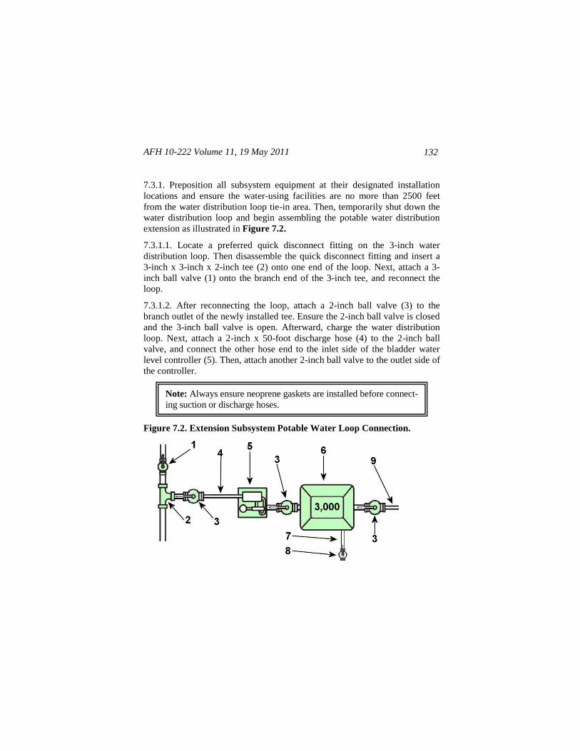
AFH 10-222 Volume 11, 19 May 2011
132
7.3.1. Preposition all subsystem equipment at their designated installation
locations and ensure the water-using facilities are no more than 2500 feet
from the water distribution loop tie-in area. Then, temporarily shut down the
water distribution loop and begin assembling the potable water distribution
extension as illustrated in Figure 7.2.
7.3.1.1. Locate a preferred quick disconnect fitting on the 3-inch water
distribution loop. Then disassemble the quick disconnect fitting and insert a
3-inch x 3-inch x 2-inch tee (2) onto one end of the loop. Next, attach a 3-
inch ball valve (1) onto the branch end of the 3-inch tee, and reconnect the
loop.
7.3.1.2. After reconnecting the loop, attach a 2-inch ball valve (3) to the
branch outlet of the newly installed tee. Ensure the 2-inch ball valve is closed
and the 3-inch ball valve is open. Afterward, charge the water distribution
loop. Next, attach a 2-inch x 50-foot discharge hose (4) to the 2-inch ball
valve, and connect the other hose end to the inlet side of the bladder water
level controller (5). Then, attach another 2-inch ball valve to the outlet side of
the controller.
Figure 7.2. Extension Subsystem Potable Water Loop Connection.
Note: Always ensure neoprene gaskets are installed before connect-
ing suction or discharge hoses.
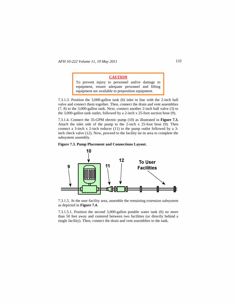
AFH 10-222 Volume 11, 19 May 2011 133
7.3.1.3. Position the 3,000-gallon tank (6) inlet in line with the 2-inch ball
valve and connect them together. Then, connect the drain and vent assemblies
(7, 8) to the 3,000-gallon tank. Next, connect another 2-inch ball valve (3) to
the 3,000-gallon tank outlet, followed by a 2-inch x 25-foot suction hose (9).
7.3.1.4. Connect the 35-GPM electric pump (10) as illustrated in Figure 7.3.
Attach the inlet side of the pump to the 2-inch x 25-foot hose (9). Then
connect a 3-inch x 2-inch reducer (11) to the pump outlet followed by a 3-
inch check valve (12). Now, proceed to the facility tie-in area to complete the
subsystem assembly.
Figure 7.3. Pump Placement and Connections Layout.
7.3.1.5. At the user-facility area, assemble the remaining extension subsystem
as depicted in Figure 7.4.
7.3.1.5.1. Position the second 3,000-gallon potable water tank (6) no more
than 50 feet away and centered between two facilities (or directly behind a
single facility). Then, connect the drain and vent assemblies to the tank.
CAUTION
To prevent injury to personnel and/or damage to
equipment, ensure adequate personnel and lifting
equipment are available to preposition equipment.
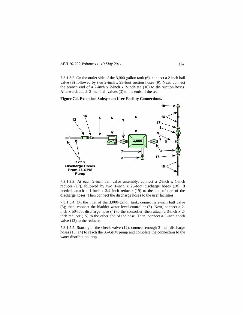
AFH 10-222 Volume 11, 19 May 2011
134
7.3.1.5.2. On the outlet side of the 3,000-gallon tank (6), connect a 2-inch ball
valve (3) followed by two 2-inch x 25-foot suction hoses (9). Next, connect
the branch end of a 2-inch x 2-inch x 2-inch tee (16) to the suction hoses.
Afterward, attach 2-inch ball valves (3) to the ends of the tee.
Figure 7.4. Extension Subsystem User-Facility Connections.
7.3.1.5.3. At each 2-inch ball valve assembly, connect a 2-inch x 1-inch
reducer (17), followed by two 1-inch x 25-foot discharge hoses (18). If
needed, attach a 1-inch x 3/4 inch reducer (19) to the end of one of the
discharge hoses. Then connect the discharge hoses to the user facilities.
7.3.1.5.4. On the inlet of the 3,000-gallon tank, connect a 2-inch ball valve
(3); then, connect the bladder water level controller (5). Next, connect a 2-
inch x 50-foot discharge hose (4) to the controller, then attach a 3-inch x 2-
inch reducer (15) to the other end of the hose. Then, connect a 3-inch check
valve (12) to the reducer.
7.3.1.5.5. Starting at the check valve (12), connect enough 3-inch discharge
hoses (13, 14) to reach the 35-GPM pump and complete the connection to the
water distribution loop.
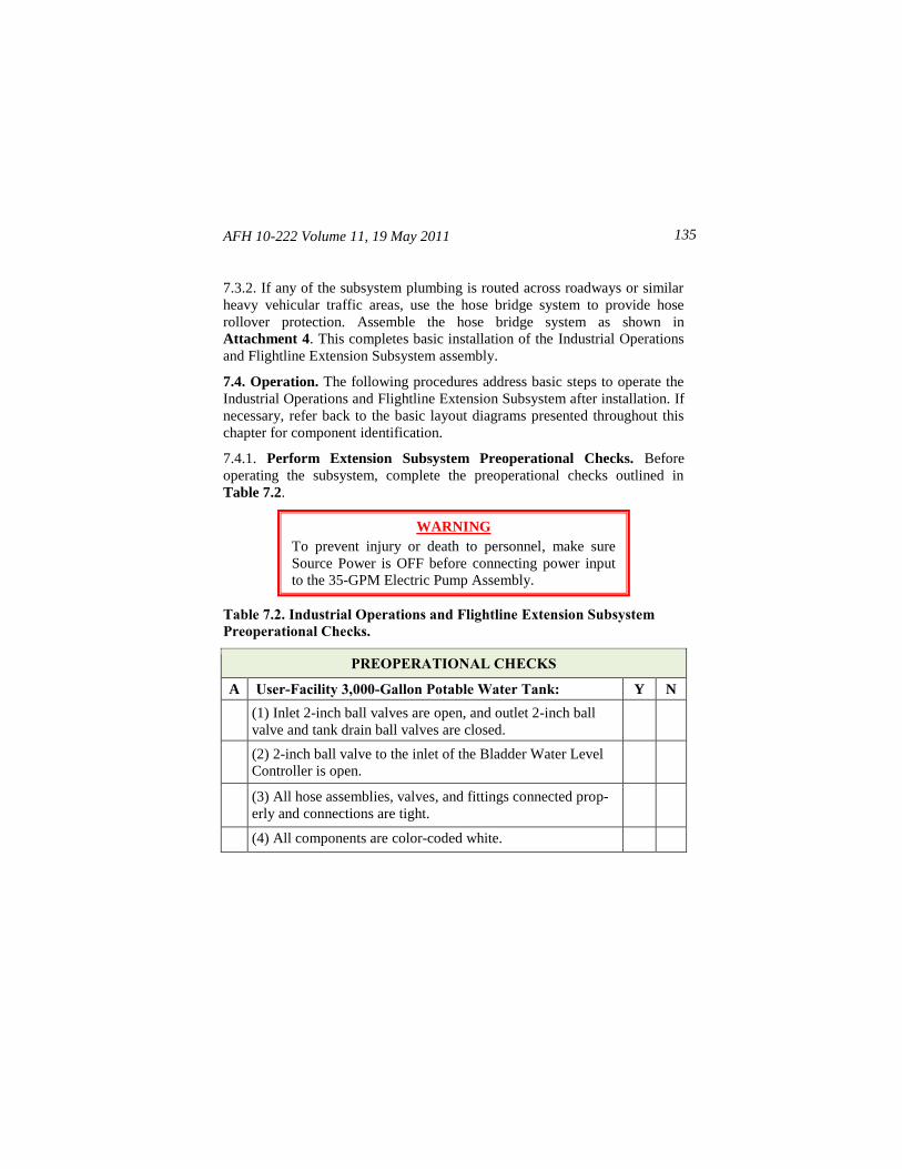
AFH 10-222 Volume 11, 19 May 2011 135
7.3.2. If any of the subsystem plumbing is routed across roadways or similar
heavy vehicular traffic areas, use the hose bridge system to provide hose
rollover protection. Assemble the hose bridge system as shown in
Attachment 4. This completes basic installation of the Industrial Operations
and Flightline Extension Subsystem assembly.
7.4. Operation. The following procedures address basic steps to operate the
Industrial Operations and Flightline Extension Subsystem after installation. If
necessary, refer back to the basic layout diagrams presented throughout this
chapter for component identification.
7.4.1. Perform Extension Subsystem Preoperational Checks. Before
operating the subsystem, complete the preoperational checks outlined in
Table 7.2.
Table 7.2. Industrial Operations and Flightline Extension Subsystem
Preoperational Checks.
PREOPERATIONAL CHECKS
A User-Facility 3,000-Gallon Potable Water Tank: Y N
(1) Inlet 2-inch ball valves are open, and outlet 2-inch ball
valve and tank drain ball valves are closed.
(2) 2-inch ball valve to the inlet of the Bladder Water Level
Controller is open.
(3) All hose assemblies, valves, and fittings connected prop-
erly and connections are tight.
(4) All components are color-coded white.
WARNING
To prevent injury or death to personnel, make sure
Source Power is OFF before connecting power input
to the 35-GPM Electric Pump Assembly.
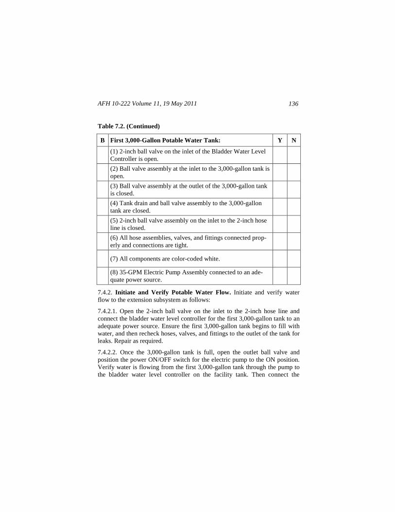
AFH 10-222 Volume 11, 19 May 2011
136
Table 7.2. (Continued)
B First 3,000-Gallon Potable Water Tank: Y N
(1) 2-inch ball valve on the inlet of the Bladder Water Level
Controller is open.
(2) Ball valve assembly at the inlet to the 3,000-gallon tank is
open.
(3) Ball valve assembly at the outlet of the 3,000-gallon tank
is closed.
(4) Tank drain and ball valve assembly to the 3,000-gallon
tank are closed.
(5) 2-inch ball valve assembly on the inlet to the 2-inch hose
line is closed.
(6) All hose assemblies, valves, and fittings connected prop-
erly and connections are tight.
(7) All components are color-coded white.
(8) 35-GPM Electric Pump Assembly connected to an ade-
quate power source.
7.4.2. Initiate and Verify Potable Water Flow. Initiate and verify water
flow to the extension subsystem as follows:
7.4.2.1. Open the 2-inch ball valve on the inlet to the 2-inch hose line and
connect the bladder water level controller for the first 3,000-gallon tank to an
adequate power source. Ensure the first 3,000-gallon tank begins to fill with
water, and then recheck hoses, valves, and fittings to the outlet of the tank for
leaks. Repair as required.
7.4.2.2. Once the 3,000-gallon tank is full, open the outlet ball valve and
position the power ON/OFF switch for the electric pump to the ON position.
Verify water is flowing from the first 3,000-gallon tank through the pump to
the bladder water level controller on the facility tank. Then connect the
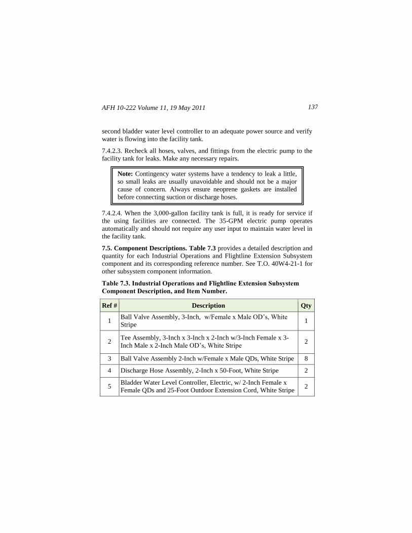
AFH 10-222 Volume 11, 19 May 2011 137
second bladder water level controller to an adequate power source and verify
water is flowing into the facility tank.
7.4.2.3. Recheck all hoses, valves, and fittings from the electric pump to the
facility tank for leaks. Make any necessary repairs.
7.4.2.4. When the 3,000-gallon facility tank is full, it is ready for service if
the using facilities are connected. The 35-GPM electric pump operates
automatically and should not require any user input to maintain water level in
the facility tank.
7.5. Component Descriptions. Table 7.3 provides a detailed description and
quantity for each Industrial Operations and Flightline Extension Subsystem
component and its corresponding reference number. See T.O. 40W4-21-1 for
other subsystem component information.
Table 7.3. Industrial Operations and Flightline Extension Subsystem
Component Description, and Item Number.
Ref # Description Qty
1 Ball Valve Assembly, 3-Inch, w/Female x Male OD’s, White
Stripe 1
2 Tee Assembly, 3-Inch x 3-Inch x 2-Inch w/3-Inch Female x 3-
Inch Male x 2-Inch Male OD’s, White Stripe 2
3 Ball Valve Assembly 2-Inch w/Female x Male QDs, White Stripe 8
4 Discharge Hose Assembly, 2-Inch x 50-Foot, White Stripe 2
5 Bladder Water Level Controller, Electric, w/ 2-Inch Female x
Female QDs and 25-Foot Outdoor Extension Cord, White Stripe 2
Note: Contingency water systems have a tendency to leak a little,
so small leaks are usually unavoidable and should not be a major
cause of concern. Always ensure neoprene gaskets are installed
before connecting suction or discharge hoses.
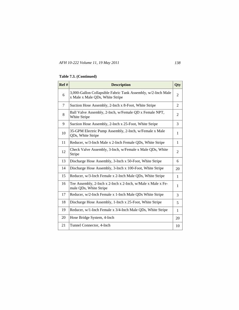
AFH 10-222 Volume 11, 19 May 2011
138
Table 7.3. (Continued)
Ref # Description Qty
6 3,000-Gallon Collapsible Fabric Tank Assembly, w/2-Inch Male
x Male x Male QDs, White Stripe 2
7 Suction Hose Assembly, 2-Inch x 8-Foot, White Stripe 2
8 Ball Valve Assembly, 2-Inch, w/Female QD x Female NPT,
White Stripe 2
9 Suction Hose Assembly, 2-Inch x 25-Foot, White Stripe 3
10 35-GPM Electric Pump Assembly, 2-Inch, w/Female x Male
QDs, White Stripe 1
11 Reducer, w/3-Inch Male x 2-Inch Female QDs, White Stripe 1
12 Check Valve Assembly, 3-Inch, w/Female x Male QDs, White
Stripe 2
13 Discharge Hose Assembly, 3-Inch x 50-Foot, White Stripe 6
14 Discharge Hose Assembly, 3-Inch x 100-Foot, White Stripe 20
15 Reducer, w/3-Inch Female x 2-Inch Male QDs, White Stripe 1
16 Tee Assembly, 2-Inch x 2-Inch x 2-Inch, w/Male x Male x Fe-
male QDs, White Stripe 1
17 Reducer, w/2-Inch Female x 1-Inch Male QDs White Stripe 3
18 Discharge Hose Assembly, 1-Inch x 25-Foot, White Stripe 5
19 Reducer, w/1-Inch Female x 3/4-Inch Male QDs, White Stripe 1
20 Hose Bridge System, 4-Inch 20
21 Tunnel Connector, 4-Inch 10
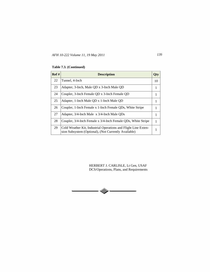
AFH 10-222 Volume 11, 19 May 2011 139
Table 7.3. (Continued)
Ref # Description Qty
22 Tunnel, 4-Inch 10
23 Adapter, 3-Inch, Male QD x 3-Inch Male QD 1
24 Coupler, 3-Inch Female QD x 3-Inch Female QD 1
25 Adapter, 1-Inch Male QD x 1-Inch Male QD 1
26 Coupler, 1-Inch Female x 1-Inch Female QDs, White Stripe 1
27 Adapter, 3/4-Inch Male x 3/4-Inch Male QDs 1
28 Coupler, 3/4-Inch Female x 3/4-Inch Female QDs, White Stripe 1
29 Cold Weather Kit, Industrial Operations and Flight Line Exten-
sion Subsystem (Optional), (Not Currently Available) 1
HERBERT J. CARLISLE, Lt Gen, USAF
DCS/Operations, Plans, and Requirements
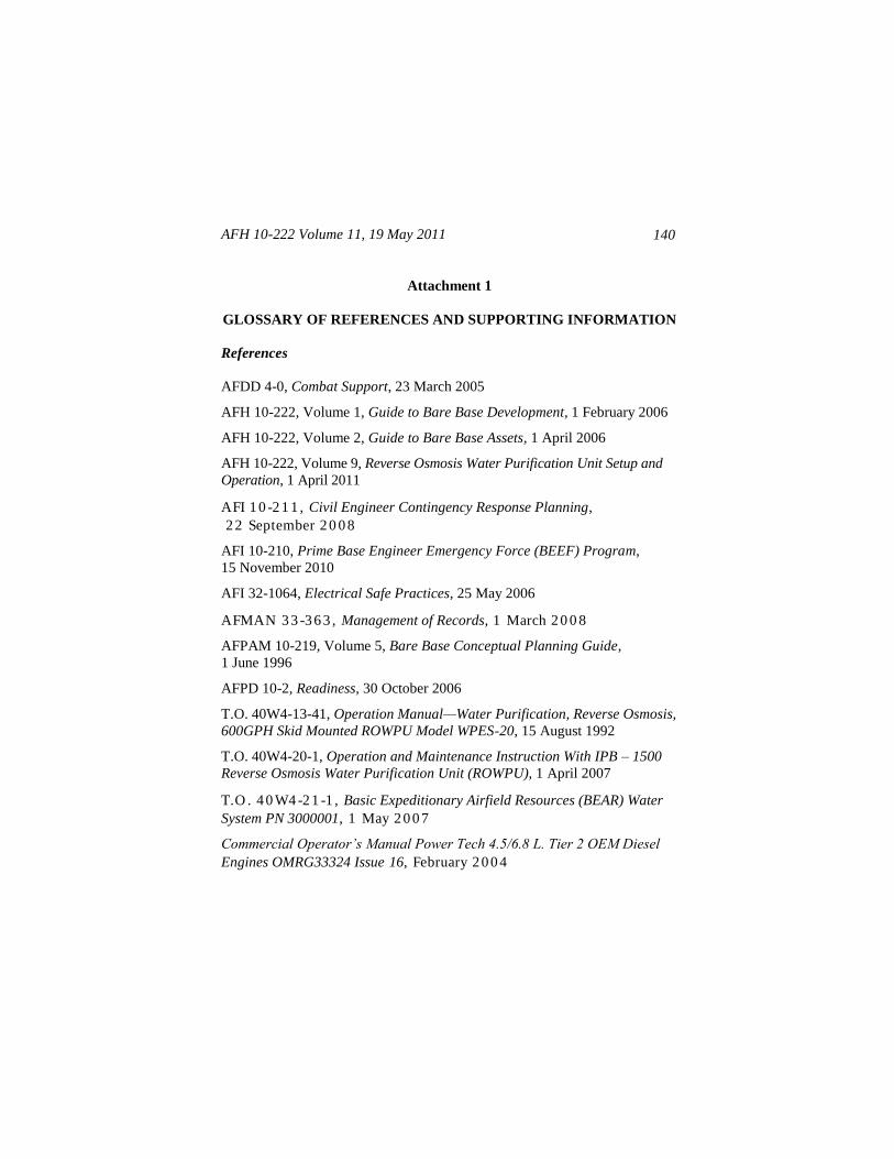
AFH 10-222 Volume 11, 19 May 2011
140
Attachment 1
GLOSSARY OF REFERENCES AND SUPPORTING INFORMATION
References
AFDD 4-0, Combat Support, 23 March 2005
AFH 10-222, Volume 1, Guide to Bare Base Development, 1 February 2006
AFH 10-222, Volume 2, Guide to Bare Base Assets, 1 April 2006
AFH 10-222, Volume 9, Reverse Osmosis Water Purification Unit Setup and
Operation, 1 April 2011
AFI 1 0 -2 1 1 , Civil Engineer Contingency Response Planning,
2 2 September 2 0 0 8
AFI 10-210, Prime Base Engineer Emergency Force (BEEF) Program,
15 November 2010
AFI 32-1064, Electrical Safe Practices, 25 May 2006
AFMAN 3 3 -3 6 3 , Management of Records, 1 March 2 0 0 8
AFPAM 10-219, Volume 5, Bare Base Conceptual Planning Guide,
1 June 1996
AFPD 10-2, Readiness, 30 October 2006
T.O. 40W4-13-41, Operation Manual—Water Purification, Reverse Osmosis,
600GPH Skid Mounted ROWPU Model WPES-20, 15 August 1992
T.O. 40W4-20-1, Operation and Maintenance Instruction With IPB – 1500
Reverse Osmosis Water Purification Unit (ROWPU), 1 April 2007
T.O . 4 0 W4 -2 1 -1 , Basic Expeditionary Airfield Resources (BEAR) Water
System PN 3000001, 1 May 2 0 0 7
Commercial Operator’s Manual Power Tech 4.5/6.8 L. Tier 2 OEM Diesel
Engines OMRG33324 Issue 16, February 2 0 0 4
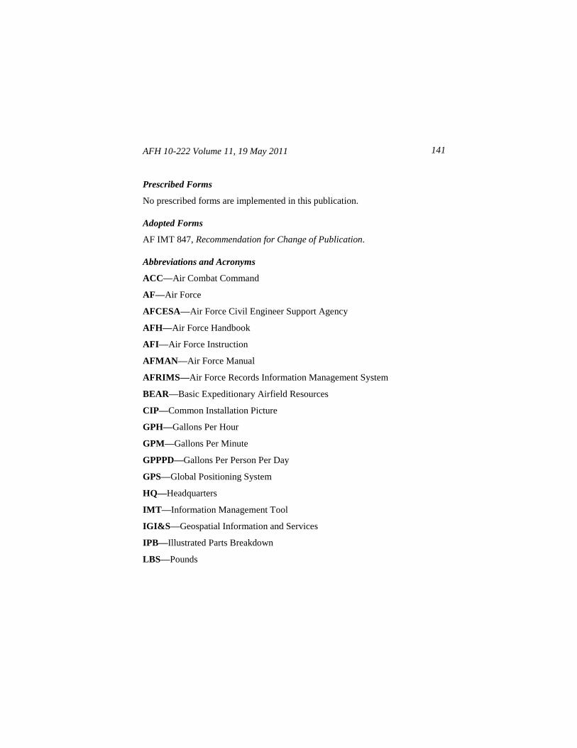
AFH 10-222 Volume 11, 19 May 2011 141
Prescribed Forms
No prescribed forms are implemented in this publication.
Adopted Forms
AF IMT 847, Recommendation for Change of Publication.
Abbreviations and Acronyms
ACC—Air Combat Command
AF—Air Force
AFCESA—Air Force Civil Engineer Support Agency
AFH—Air Force Handbook
AFI—Air Force Instruction
AFMAN—Air Force Manual
AFRIMS—Air Force Records Information Management System
BEAR—Basic Expeditionary Airfield Resources
CIP—Common Installation Picture
GPH—Gallons Per Hour
GPM—Gallons Per Minute
GPPPD—Gallons Per Person Per Day
GPS—Global Positioning System
HQ—Headquarters
IMT—Information Management Tool
IGI&S—Geospatial Information and Services
IPB—Illustrated Parts Breakdown
LBS—Pounds
AFH 10-222 Volume 11, 19 May 2011
142
MAJCOM—Major Command
NPT—National Pipe Thread
NST—National Standard Threads
OPR—Office of Primary Responsibility
PPE—Personal Protective Equipment
PSI—Pounds Per Square Inch
PVC—Polyvinyl Chloride
QD—Quick Disconnect
RBC—Reach-Back Center
RDS—Records Disposition Schedule
ROWPU—Reverse Osmosis Water Purification Unit
SRS—Source Run Subsystem
TF—Tank Farm
TM—Technical Manual
TO—Technical Order
V—Volts
VAC—Volts Alternating Current
WOA—Water Operations Area
WPS—Water Production Subsystem
Terms
Air Force Civil Engineer Support Agency (AFCESA)—A field operating
agency (FOA) located at Tyndall Air Force Base, Florida. The Directorate of
Readiness Support (HQ AFCESA/CEX) acts as the Air Force program
manager for Base Civil Engineer (BCE) Contingency Response Planning.
AFH 10-222 Volume 11, 19 May 2011 143
Bare Base—An installation having minimum essential facilities to house,
sustain, and support operations to include, if required, a stabilized runway,
taxiways, and aircraft parking areas. A bare base must have a source of water
that can be made potable. Other requirements to operate under bare base
conditions form a necessary part of the force package deployed to the bare
base.
Basic Expeditionary Airfield Resources (BEAR)—Facilities, equipment,
and basic infrastructure to support the beddown of deployed forces and aircraft
at austere locations; a critical capability to fielding expeditionary aerospace
forces. Also known as BEAR, the resources include tents, field kitchens, latrine
systems, shop equipment, electrical and power systems, runway systems,
aircraft shelters, and water distribution systems needed to sustain operations.
Chemical, Biological, Radiological and Nuclear (CBRN) Defense—The
methods, plans, procedures and training required to establish defense
measures against the effects of attack by nuclear weapons or chemical and
biological agents.
National Pipe Thread—A U.S. standard for tapered threads used to join pipes
and fittings.
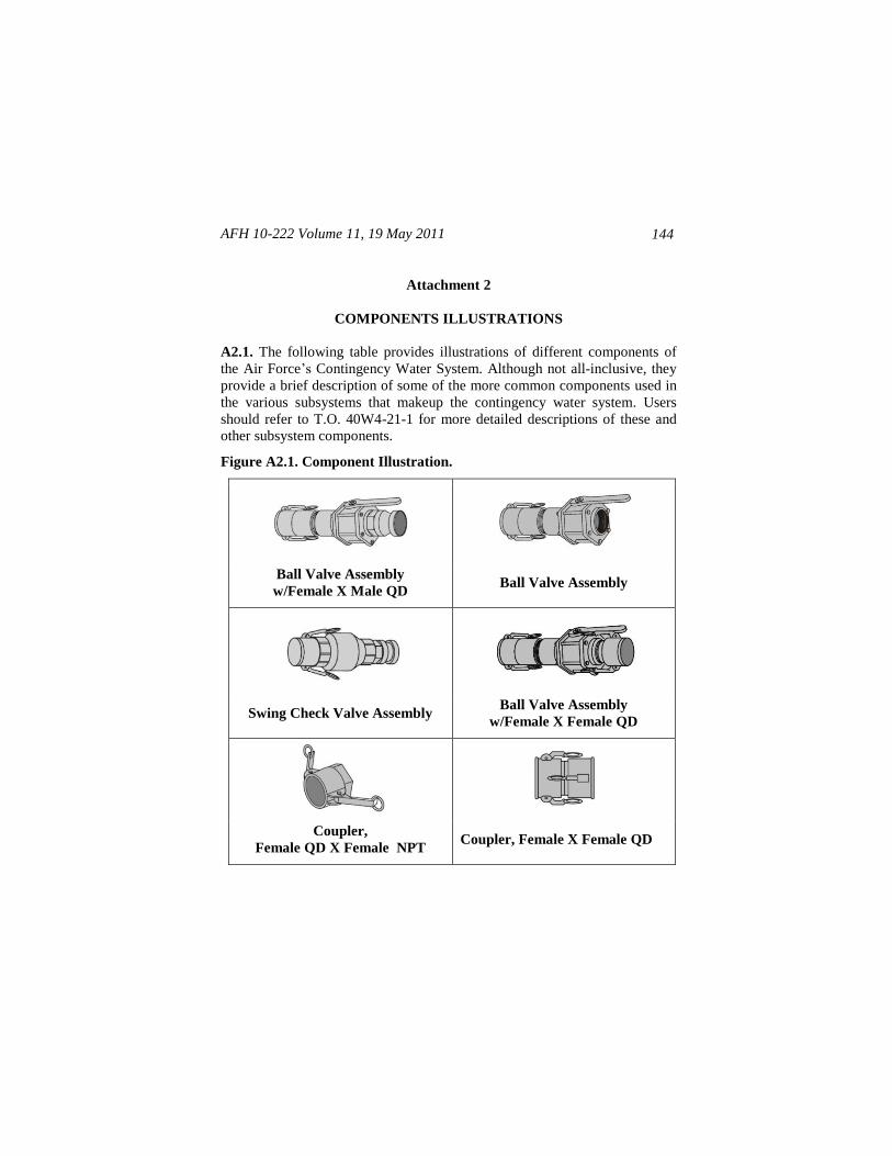
AFH 10-222 Volume 11, 19 May 2011
144
Attachment 2
COMPONENTS ILLUSTRATIONS
A2.1. The following table provides illustrations of different components of
the Air Force’s Contingency Water System. Although not all-inclusive, they
provide a brief description of some of the more common components used in
the various subsystems that makeup the contingency water system. Users
should refer to T.O. 40W4-21-1 for more detailed descriptions of these and
other subsystem components.
Figure A2.1. Component Illustration.
Ball Valve Assembly
w/Female X Male QD Ball Valve Assembly
Swing Check Valve Assembly Ball Valve Assembly
w/Female X Female QD
Coupler,
Female QD X Female NPT Coupler, Female X Female QD
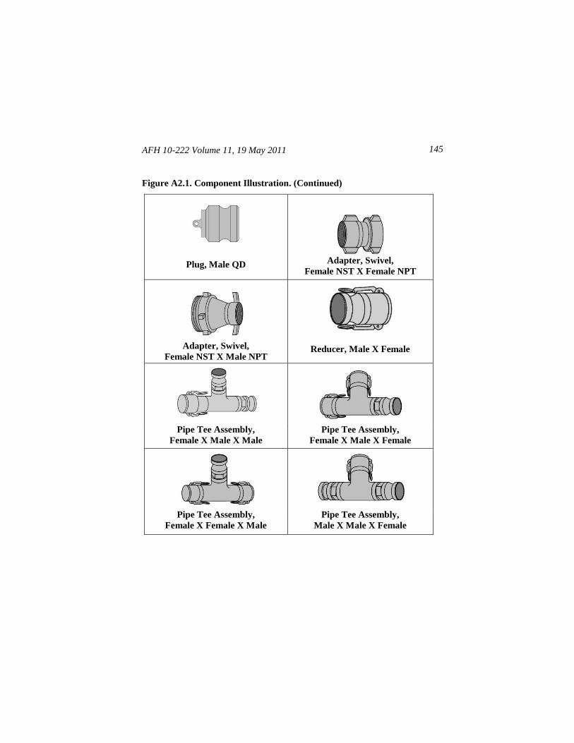
AFH 10-222 Volume 11, 19 May 2011 145
Figure A2.1. Component Illustration. (Continued)
Plug, Male QD Adapter, Swivel,
Female NST X Female NPT
Adapter, Swivel,
Female NST X Male NPT Reducer, Male X Female
Pipe Tee Assembly,
Female X Male X Male
Pipe Tee Assembly,
Female X Male X Female
Pipe Tee Assembly,
Female X Female X Male
Pipe Tee Assembly,
Male X Male X Female
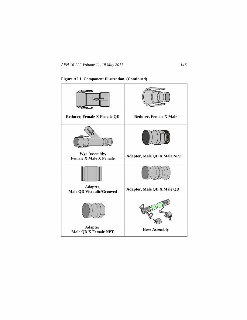
AFH 10-222 Volume 11, 19 May 2011
146
Figure A2.1. Component Illustration. (Continued)
Reducer, Female X Female QD Reducer, Female X Male
Wye Assembly,
Female X Male X Female Adapter, Male QD X Male NPT
Adapter,
Male QD Victaulic/Grooved Adapter, Male QD X Male QD
Adapter,
Male QD X Female NPT Hose Assembly
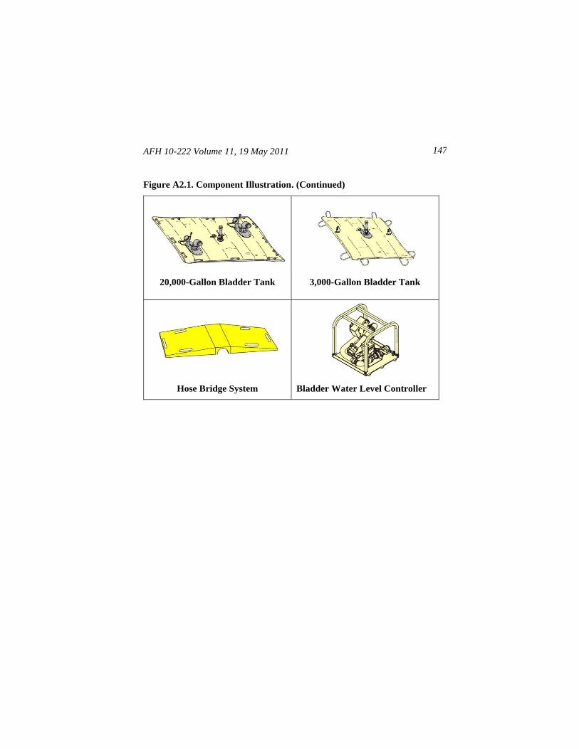
AFH 10-222 Volume 11, 19 May 2011 147
Figure A2.1. Component Illustration. (Continued)
20,000-Gallon Bladder Tank 3,000-Gallon Bladder Tank
Hose Bridge System Bladder Water Level Controller
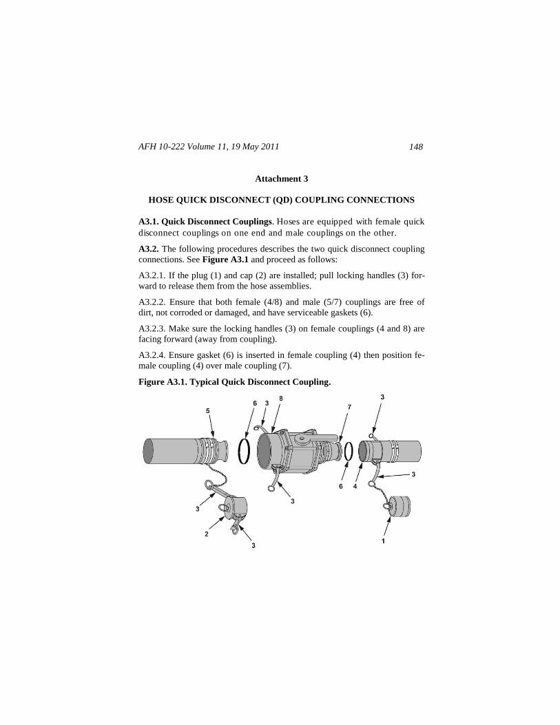
AFH 10-222 Volume 11, 19 May 2011
148
Attachment 3
HOSE QUICK DISCONNECT (QD) COUPLING CONNECTIONS
A3.1. Quick Disconnect Couplings. Hoses are equipped with female quick
disconnect couplings on one end and male couplings on the other.
A3.2. The following procedures describes the two quick disconnect coupling
connections. See Figure A3.1 and proceed as follows:
A3.2.1. If the plug (1) and cap (2) are installed; pull locking handles (3) for-
ward to release them from the hose assemblies.
A3.2.2. Ensure that both female (4/8) and male (5/7) couplings are free of
dirt, not corroded or damaged, and have serviceable gaskets (6).
A3.2.3. Make sure the locking handles (3) on female couplings (4 and 8) are
facing forward (away from coupling).
A3.2.4. Ensure gasket (6) is inserted in female coupling (4) then position fe-
male coupling (4) over male coupling (7).
Figure A3.1. Typical Quick Disconnect Coupling.
AFH 10-222 Volume 11, 19 May 2011 149
A3.2.5. Rotate locking handles (3) backward and press down until they are in
horizontal alignment with the hose assembly.
A3.2.6. Ensure gasket (6) is inserted in the female coupling (8), then position
male coupling (5) in female coupling (8).
A3.2.7. Rotate the locking handles (3) backward and press down until they
are in horizontal alignment with the hose assembly.
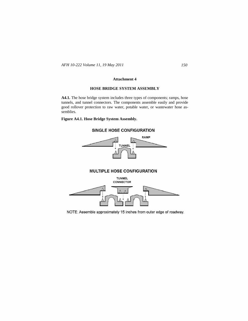
AFH 10-222 Volume 11, 19 May 2011
150
Attachment 4
HOSE BRIDGE SYSTEM ASSEMBLY
A4.1. The hose bridge system includes three types of components; ramps, hose
tunnels, and tunnel connectors. The components assemble easily and provide
good rollover protection to raw water, potable water, or wastewater hose as-
semblies.
Figure A4.1. Hose Bridge System Assembly.
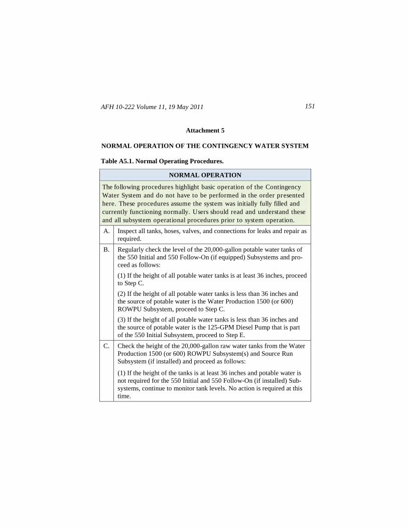
AFH 10-222 Volume 11, 19 May 2011 151
Attachment 5
NORMAL OPERATION OF THE CONTINGENCY WATER SYSTEM
Table A5.1. Normal Operating Procedures.
NORMAL OPERATION
The following procedures highlight basic operation of the Contingency
Water System and do not have to be performed in the order presented
here. These procedures assume the system was initially fully filled and
currently functioning normally. Users should read and understand these
and all subsystem operational procedures prior to system operation.
A. Inspect all tanks, hoses, valves, and connections for leaks and repair as
required.
B. Regularly check the level of the 20,000-gallon potable water tanks of
the 550 Initial and 550 Follow-On (if equipped) Subsystems and pro-
ceed as follows:
(1) If the height of all potable water tanks is at least 36 inches, proceed
to Step C.
(2) If the height of all potable water tanks is less than 36 inches and
the source of potable water is the Water Production 1500 (or 600)
ROWPU Subsystem, proceed to Step C.
(3) If the height of all potable water tanks is less than 36 inches and
the source of potable water is the 125-GPM Diesel Pump that is part
of the 550 Initial Subsystem, proceed to Step E.
C. Check the height of the 20,000-gallon raw water tanks from the Water
Production 1500 (or 600) ROWPU Subsystem(s) and Source Run
Subsystem (if installed) and proceed as follows:
(1) If the height of the tanks is at least 36 inches and potable water is
not required for the 550 Initial and 550 Follow-On (if installed) Sub-
systems, continue to monitor tank levels. No action is required at this
time.
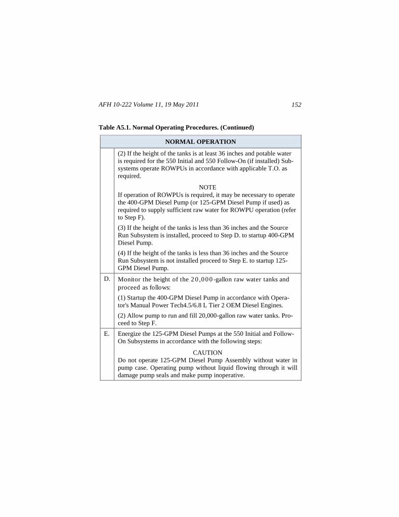
AFH 10-222 Volume 11, 19 May 2011
152
Table A5.1. Normal Operating Procedures. (Continued)
NORMAL OPERATION
(2) If the height of the tanks is at least 36 inches and potable water
is required for the 550 Initial and 550 Follow-On (if installed) Sub-
systems operate ROWPUs in accordance with applicable T.O. as
required.
NOTE
If operation of ROWPUs is required, it may be necessary to operate
the 400-GPM Diesel Pump (or 125-GPM Diesel Pump if used) as
required to supply sufficient raw water for ROWPU operation (refer
to Step F).
(3) If the height of the tanks is less than 36 inches and the Source
Run Subsystem is installed, proceed to Step D. to startup 400-GPM
Diesel Pump.
(4) If the height of the tanks is less than 36 inches and the Source
Run Subsystem is not installed proceed to Step E. to startup 125-
GPM Diesel Pump.
D. Monitor the height of the 2 0 ,0 0 0 -gallon raw water tanks and
proceed as follows:
(1) Startup the 400-GPM Diesel Pump in accordance with Opera-
tor's Manual Power Tech4.5/6.8 L Tier 2 OEM Diesel Engines.
(2) Allow pump to run and fill 20,000-gallon raw water tanks. Pro-
ceed to Step F.
E. Energize the 125-GPM Diesel Pumps at the 550 Initial and Follow-
On Subsystems in accordance with the following steps:
CAUTION
Do not operate 125-GPM Diesel Pump Assembly without water in
pump case. Operating pump without liquid flowing through it will
damage pump seals and make pump inoperative.
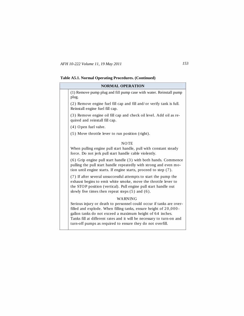
AFH 10-222 Volume 11, 19 May 2011 153
Table A5.1. Normal Operating Procedures. (Continued)
NORMAL OPERATION
(1) Remove pump plug and fill pump case with water. Reinstall pump
plug.
(2 ) Remove engine fuel fill cap and fill and/ or verify tank is full.
Reinstall engine fuel fill cap.
(3 ) Remove engine oil fill cap and check oil level. Add oil as re-
quired and reinstall fill cap.
(4 ) O pen fuel valve.
(5 ) Move throttle lever to run position (right).
NO TE
When pulling engine pull start handle, pull with constant steady
force. Do not jerk pull start handle cable violently.
(6 ) Grip engine pull start handle (3 ) with both hands. Commence
pulling the pull start handle repeatedly with strong and even mo-
tion until engine starts. If engine starts, proceed to step (7 ).
(7 ) If after several unsuccessful attempts to start the pump the
exhaust begins to emit white smoke, move the throttle lever to
the STO P position (vertical). Pull engine pull start handle out
slowly five times then repeat steps (5 ) and (6 ).
WARNING
Serious injury or death to personnel could occur if tanks are over-
filled and explode. When filling tanks, ensure height of 2 0 ,0 0 0 -
gallon tanks do not exceed a maximum height of 6 4 inches.
Tanks fill at different rates and it will be necessary to turn-on and
turn-off pumps as required to ensure they do not overfill.
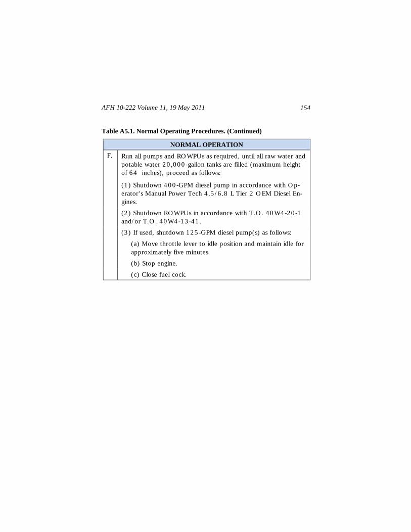
AFH 10-222 Volume 11, 19 May 2011
154
Table A5.1. Normal Operating Procedures. (Continued)
NORMAL OPERATION
F. Run all pumps and RO WPUs as required, until all raw water and
potable water 2 0 ,0 0 0 -gallon tanks are filled (maximum height
of 6 4 inches), proceed as follows:
(1 ) Shutdown 4 0 0 -GPM diesel pump in accordance with O p-
erator' s Manual Power Tech 4 .5 / 6 .8 L Tier 2 O EM Diesel En-
gines.
(2 ) Shutdown RO WPUs in accordance with T.O . 4 0 W4 -2 0 -1
and/ or T.O . 4 0 W4 -1 3 -4 1 .
(3 ) If used, shutdown 1 2 5 -GPM diesel pump(s) as follows:
(a) Move throttle lever to idle position and maintain idle for
approximately five minutes.
(b) Stop engine.
(c) Close fuel cock.