Embed Size (px)
Citation preview
AIR FORCE HANDBOOK 10-222, VOLUME 24
20 April 2011
THIS PUBLICATION CONTAINS COPYRIGHTED MATERIAL
BY ORDER OF THE AIR FORCE HANDBOOK 10-222
SECRETARY OF THE AIR FORCE VOLUME 24
20 April 2011
Operations
PAVEMENT MILLING OPERATIONS
ACCESSIBILITY: Publications and forms are available for downloading or
ordering on the e-Publishing website at www.e-publishing.af.mil.
RELEASABILITY: No releasability restrictions on this publication.
OPR: HQ AFCESA/CEXX Certified by: HQ USAF/A7CX
(Col Jeffery A. Vinger)
Pages: 69
This handbook supports Air Force Instruction (AFI) 10-209, RED HORSE
Program, and provides guidance on pavement milling operations for RED
HORSE personnel. This handbook applies to Air Force RED HORSE, or
other Civil Engineering, personnel including Air National Guard (ANG)
units and Air Force Reserve Command (AFRC) personnel whom may be
tasked to perform pavement milling operations. Refer recommended changes
and questions about this publication to the Office of Primary Responsibility
(OPR) using AF Form 847, Recommendation for Change of Publication;
route AF IMT 847s from the field through Major Command (MAJCOM)
publications/forms managers. Ensure that all records created as a result of
processes prescribed in this publication are maintained in accordance with
Air Force Manual (AFMAN) 33-363, Management of Records, and disposed
of in accordance with Air Force Records Disposition Schedule (RDS) in Air
Force Records Information Management System (AFRIMS) located at
https://www.my.af.mil/gcss-af61a/afrims/afrims/. The use of the name or
mark of any specific manufacturer, commercial product, commodity, or ser-
vice in this publication does not imply endorsement by the Air Force.
NOTE: Specific information about the Roadtec® RX-60C machine is from
the Operation, Service & Maintenance Manual, P.N. 200501 ©ROADTEC,
INC. 9/00. Reprinted with permission.
Certified Current 17 March 2015
AFH 10-222 Volume 24 20 April 2011 2
Page
Chapter 1—INTRODUCTION ................................................................... 6
1.1. Scope ............................................................................................ 6
1.2. Overview ...................................................................................... 6
Figure 1.1. Air Force Civil Engineer Publications Hierarchy ......................... 7
1.3. Cold Milling ................................................................................. 8
Figure 1.2. Milled Surface with Tack Coat Applied ....................................... 8
Table 1.1. Cold Milling Advantages and Disadvantages ............................... 9
1.4. Milling Machines .......................................................................... 9
Figure 1.3. Milling Machine In Action ........................................................ 10
1.5. Cutting Teeth .............................................................................. 10
Figure 1.4. Cutting Teeth ............................................................................. 10
1.6. Milling versus Heater-Planing .................................................... 10
1.7. Milled Surface ............................................................................ 11
1.8. Milled Material ........................................................................... 11
Figure 1.5. Secondary Road Surfaced with Recycled Asphalt ...................... 12
1.9. Base Course ................................................................................ 13
1.10. Reinforcing Fabric .................................................................... 13
Chapter 2—MILLING MACHINE SPECIFICATIONS ....................... 14
2.1. Machine Description .................................................................. 14
Figure 2.1. Roadtec® RX-60C Milling Machine .......................................... 14
2.2. Machine Features ........................................................................ 14
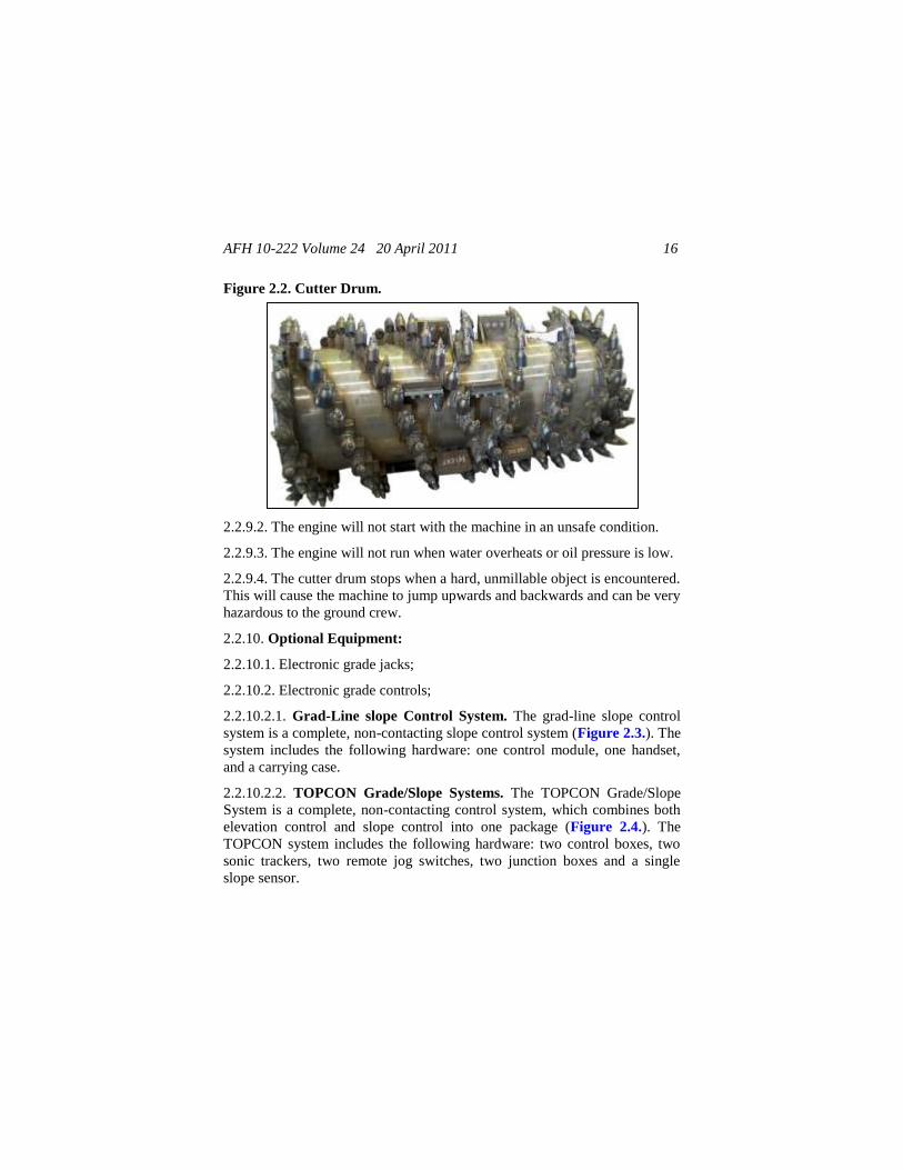
Figure 2.2. Cutter Drum ............................................................................... 16
Figure 2.3. Grad-Line Control Module and Handset .................................... 17
Figure 2.4. TOPCON Grade/Slope Control Box .......................................... 17
2.3. Component Nomenclature .......................................................... 17
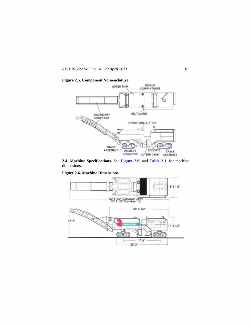
Figure 2.5. Component Nomenclature ......................................................... 18
2.4. Machine Specifications ............................................................... 18
AFH 10-222 Volume 24 20 April 2011 3
Figure 2.6. Machine Dimensions ................................................................. 18
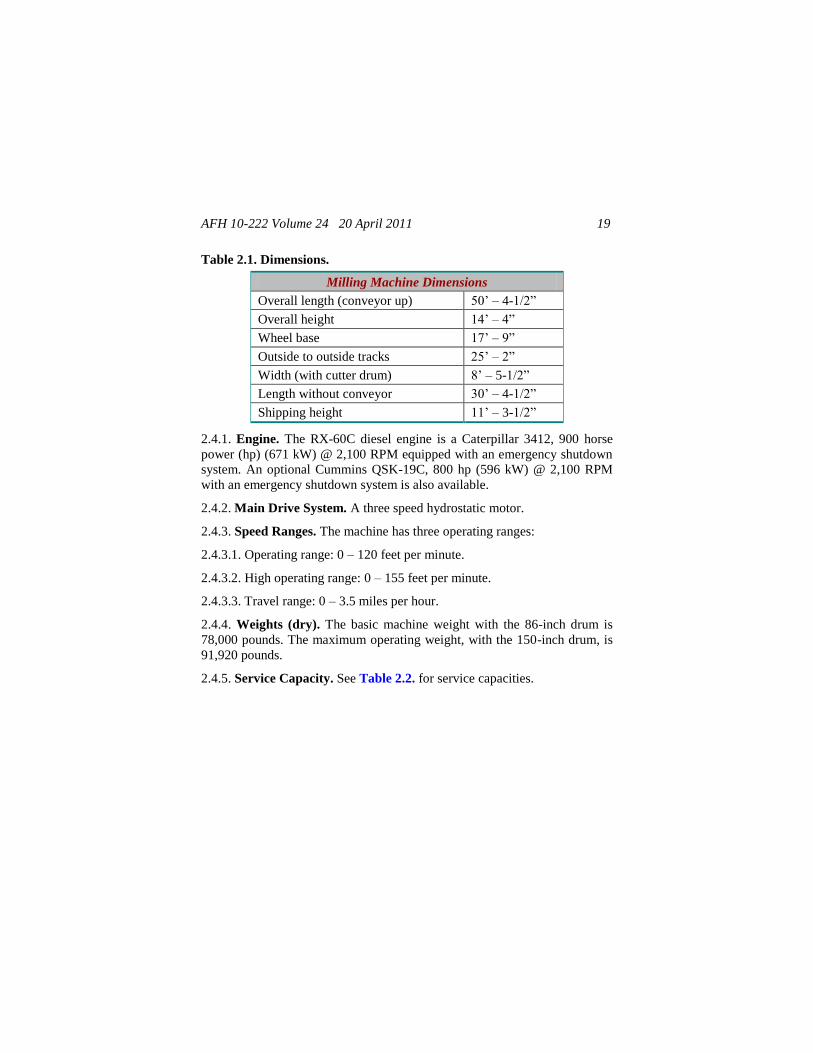
Table 2.1. Dimensions .................................................................................. 19
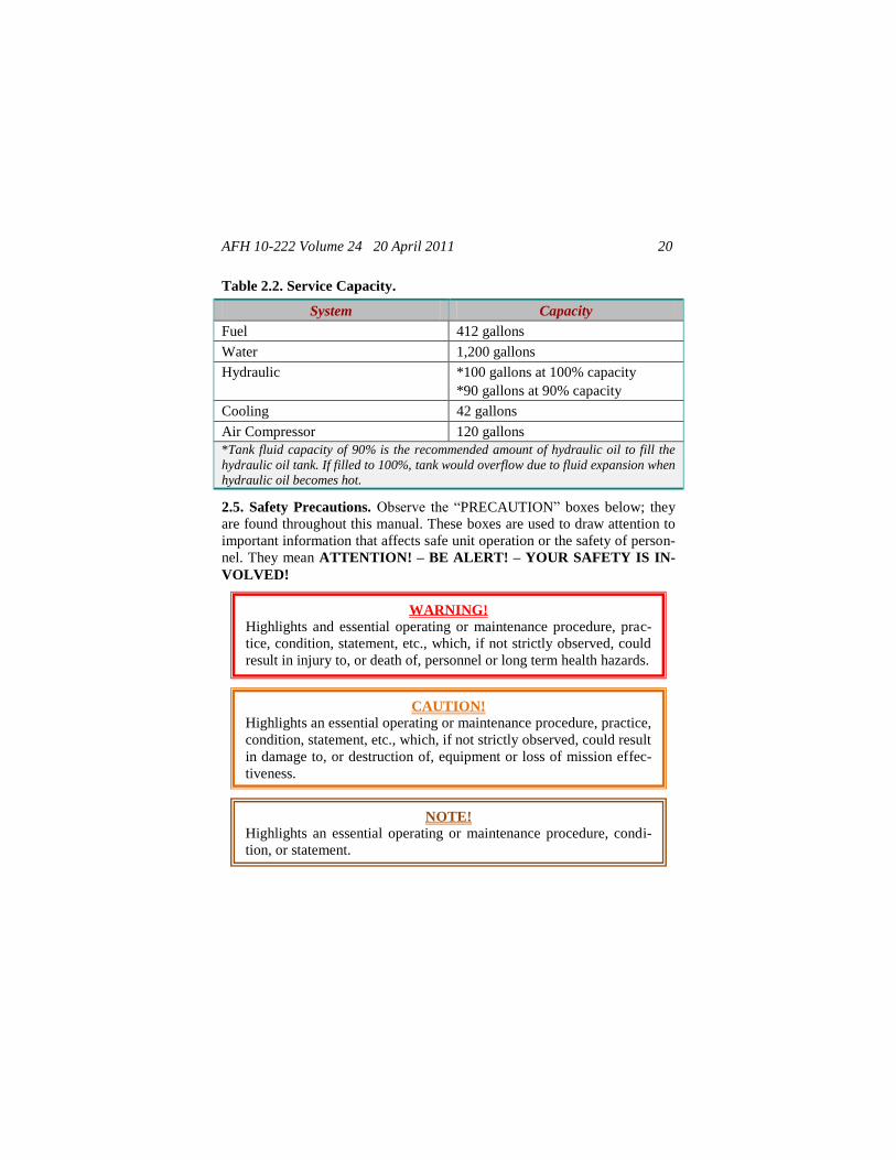
Table 2.2. Service Capacity .......................................................................... 20
2.5. Safety Precautions ...................................................................... 20
2.6. Detailed Systems Description ..................................................... 22
Figure 2.7. Caterpillar 3412E Diesel Engine ................................................ 22
Figure 2.8. Electrical Component Locations ................................................ 24
2.7. Aircraft Load Plan ...................................................................... 25
Chapter 3—MILLING MACHINE OPERATING AND
MAINTENANCE PROCEDURES ...................................... 26
3.1. Machine Familiarization .............................................................. 26
3.2. Pre-start Procedures .................................................................... 26
3.3. Starting the Engine ..................................................................... 27
3.4. Machine Operation ..................................................................... 28
Figure 3.1. Endgate Attachment ................................................................... 29
Figure 3.2. Caster Attachment ...................................................................... 29
Figure 3.3. Rear of Machine Lowered ......................................................... 30
Figure 3.4. Endgate and Caster Assembly .................................................... 30
Figure 3.5. Depth Indicator Scale ................................................................. 31
Figure 3.6. Location of Sensor Arm Locking Nut ........................................ 31
Figure 3.7. Clutch Pressure Reducing Valve ................................................ 33
Figure 3.8. Water Tank Valve Location ....................................................... 33
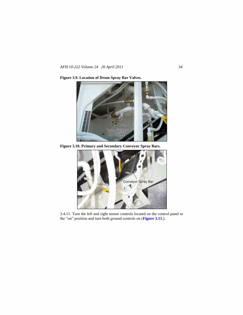
Figure 3.9. Location of Drum Spray Bar Valves .......................................... 34
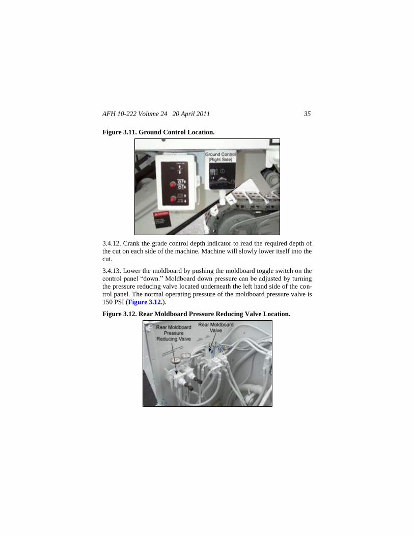
Figure 3.10. Primary and Secondary Conveyor Spray Bars ......................... 34
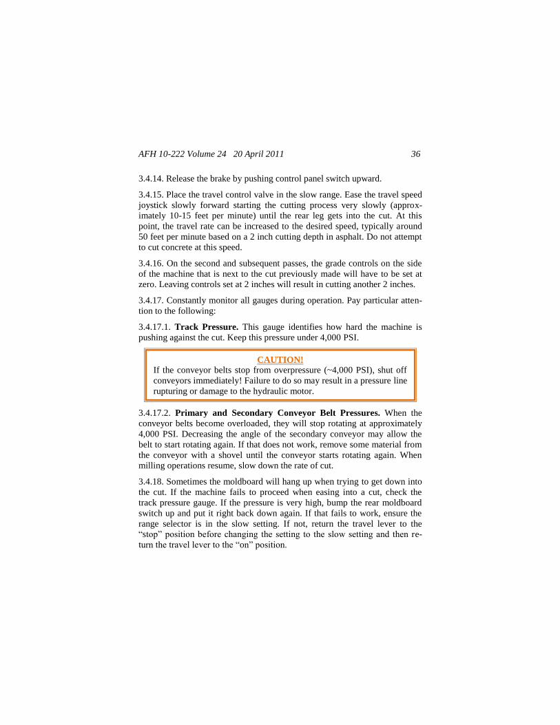
Figure 3.11. Ground Control Location ......................................................... 35
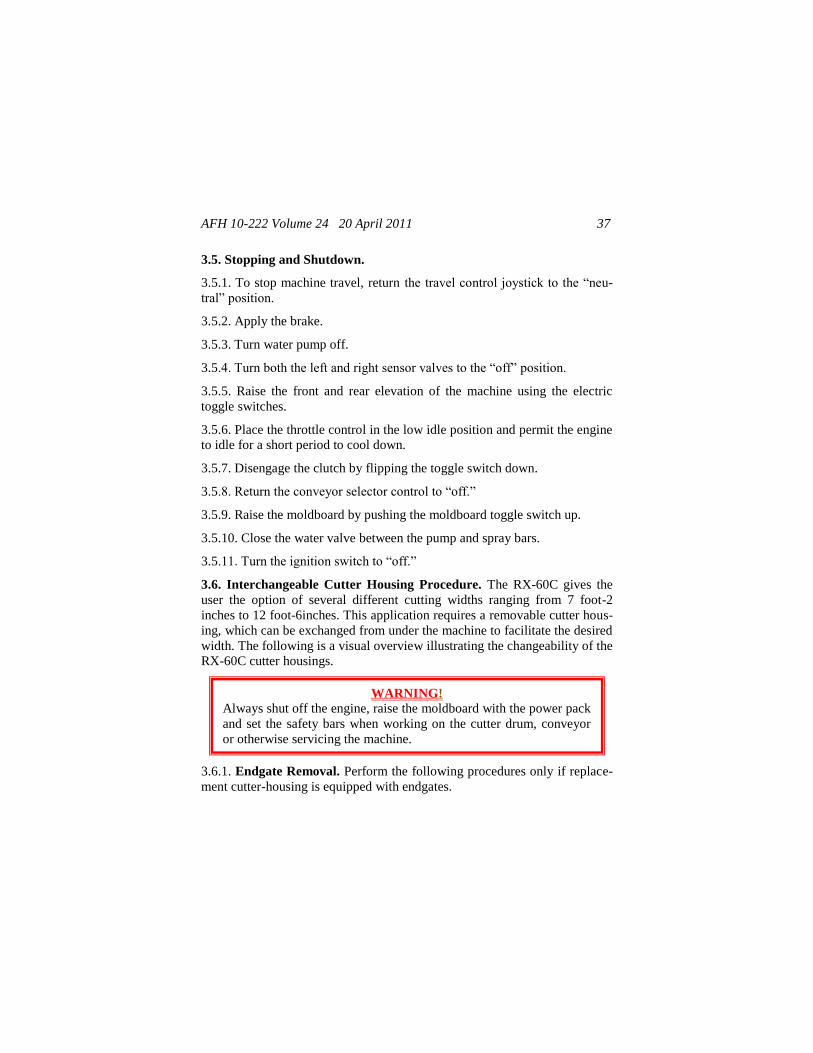
Figure 3.12. Rear Moldboard Pressure Reducing Valve Location ............... 35
3.5. Stopping and Shutdown .............................................................. 37
3.6. Interchangeable Cutter Housing Procedure ................................ 37
AFH 10-222 Volume 24 20 April 2011 4
Figure 3.13. Remove These Items for Endgate Removal ............................. 38
Figure 3.14. Endgate Bolt Location ............................................................. 38
Figure 3.15. Belt tension Cylinder and Pulley Location .............................. 39
Figure 3.16. Removing Rear Moldboard Cylinder ....................................... 40
Figure 3.17. Primary Conveyor Suspended with Side Hooks
and Chains ............................................................................... 40
Figure 3.18. Removing Primary Conveyor Suspension Pins ....................... 41
Figure 3.19. Rear Spray Bar Disconnect ...................................................... 41
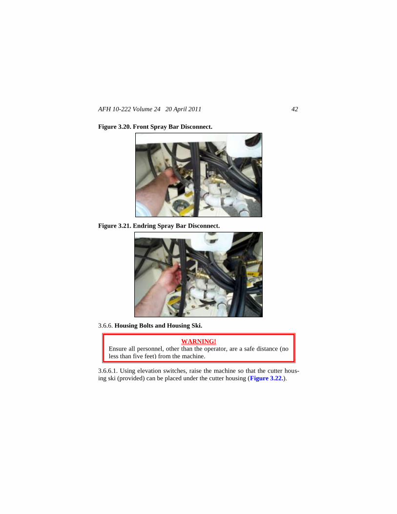
Figure 3.20. Front Spray Bar Disconnect ..................................................... 42
Figure 3.21. Endring Spray Bar Disconnect .................................................. 42
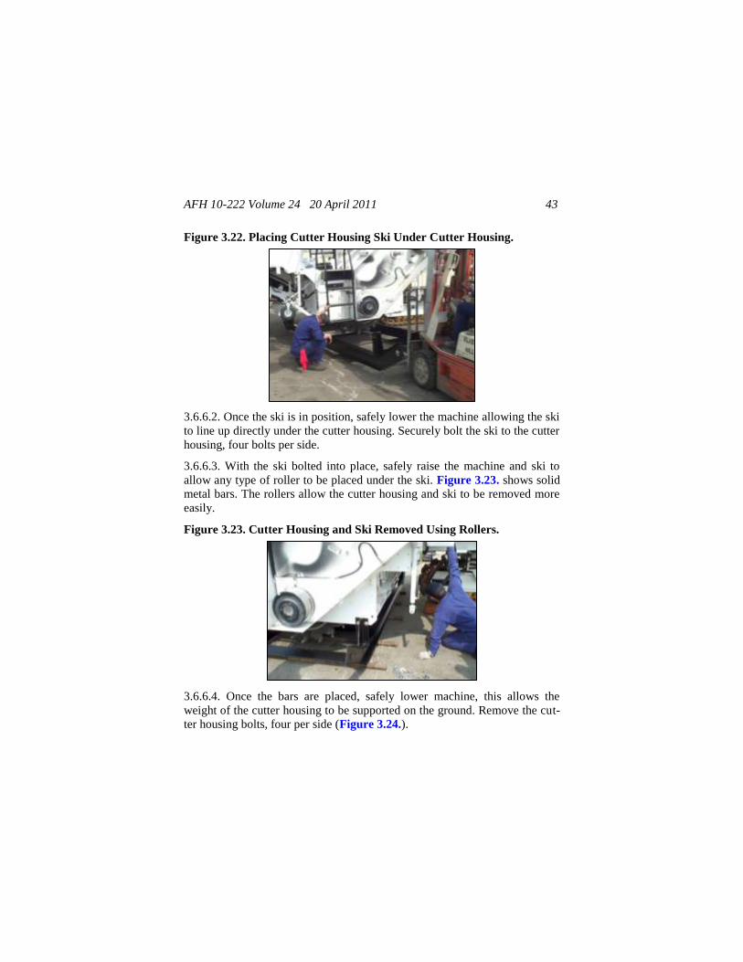
Figure 3.22. Placing Cutter Housing Ski Under Cutter Housing ................. 43
Figure 3.23. Cutter Housing and Ski Removed Using Rollers ..................... 43
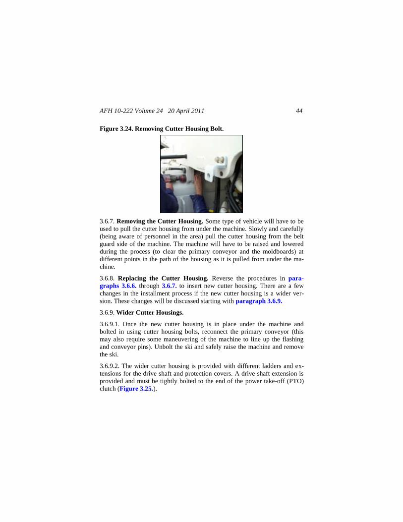
Figure 3.24. Removing Cutter Housing Bolt ................................................ 44
Figure 3.25. Preparing to Bolt Drive Shaft Extension to PTO Clutch ......... 45
3.7. Ground Level Controls ............................................................... 45
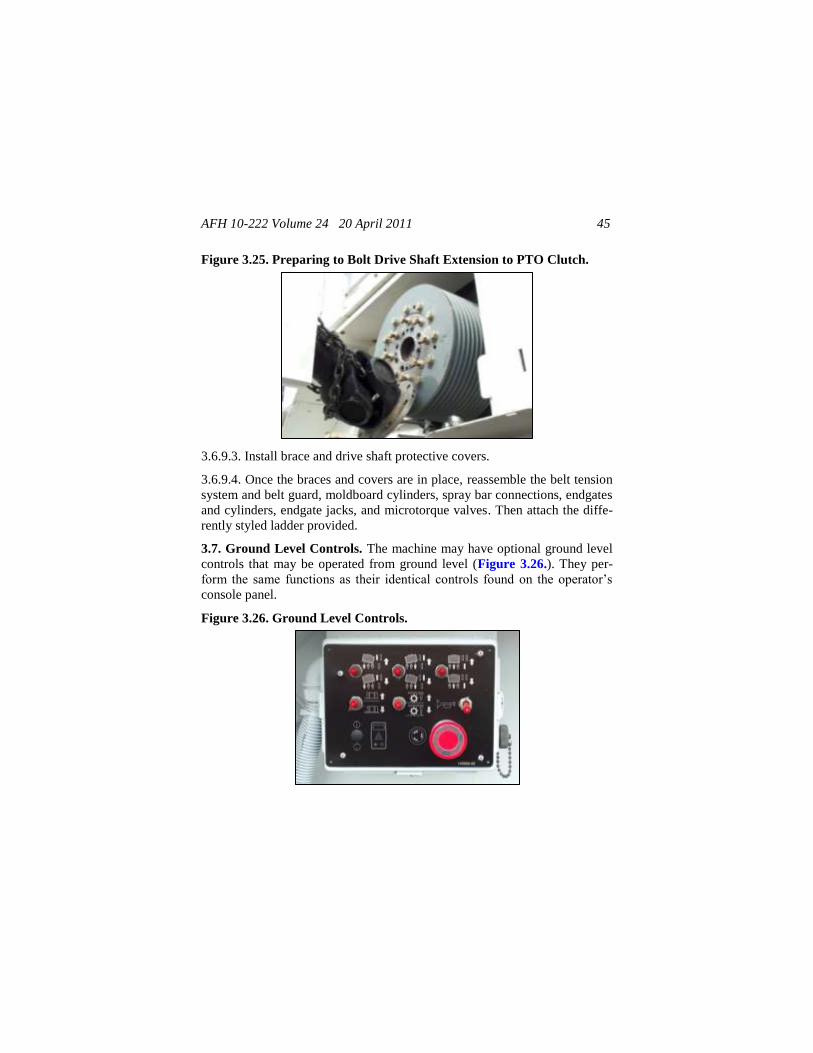
Figure 3.26. Ground Level Controls ............................................................ 45
3.8. Power Pack ................................................................................. 46
Figure 3.27. Location of On/Off Valve on Left Pressure Manifold ............. 46
Figure 3.28. Location of Power Pack Switch ............................................... 47
Figure 3.29. Location of Quick-Disconnect on Right Pressure Manifold .... 47
3.9. High Pressure Wash-down ......................................................... 48
Figure 3.30. Location of Wash-down Lever ................................................ 49
3.10. Grad-Line Slope Control System .............................................. 50
3.11. TOPCON Grade/Slope Systems ............................................... 52
3.12. Maintenance Safety Precautions ............................................... 56
Figure 3.31. Battery Disconnect Switch ....................................................... 57
3.13. Lubrication ............................................................................... 58
3.14. Changing Cutting Teeth ............................................................ 59
AFH 10-222 Volume 24 20 April 2011 5
Chapter 4—GENERAL MILLING PRACTICES .................................. 61
4.1. Milling Preparation ..................................................................... 61
4.2. Milling Operation ....................................................................... 61
4.3. Quality Control Requirements .................................................... 63
4.4. Post Operation ............................................................................ 64
Attachment 1—GLOSSARY OF REFERENCES AND SUPPORTING
INFORMATION ............................................................. 66
AFH 10-222 Volume 24 20 April 2011 6
Chapter 1
INTRODUCTION
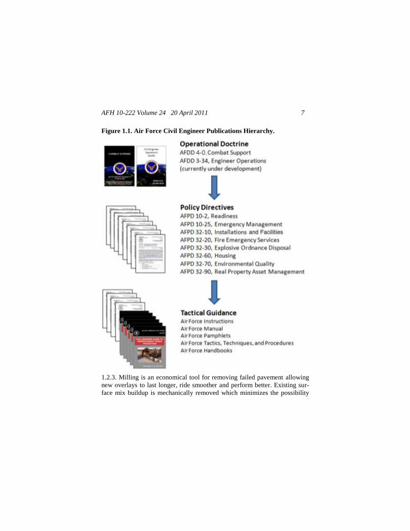
1.1. Scope. This handbook is not intended to be an all inclusive step-by-step
manual, but rather a document that will inspire additional thought during
pavement milling operations. This handbook contains tactics, techniques,
and procedures (TTPs) for use by civil engineers in supporting precepts out-
lined in Air Force Doctrine Document (AFDD) 4-0, Combat Support, and
published guidance related to Engineer Operations. It also supports imple-
mentation of Air Force Policy Directive (AFPD) 10-2, Readiness, and AFI
10-209, RED HORSE Program. This relationship is illustrated in Figure
1.1., the Air Force CE hierarchy of publications.
1.2. Overview. Worn, deteriorated roads with potholes, severe cracking, and
heavy rutting that traps water and causes hydroplaning and slick surfaces
(polished aggregate) with reduced skid resistance often require immediate
attention in the form of overlaying with new pavement. Before an existing
pavement is overlaid with new pavement the surface must be prepared.
Overlaid pavements constructed without adequate surface preparation may
not meet smoothness specifications, or may not bond to the existing pave-
ment.
1.2.1. The existing pavement should be made as smooth as possible before
being overlaid. It is difficult to make up elevation differences or smooth out
ruts by varying overlay thickness. Hot mix asphalt (HMA) tends to differen-
tially compact; a rule of thumb is that conventional mixes will initially
compact approximately 0.25 inches per 1 inch of thickness. Thus, thicker
pavements will compact more. Therefore, before applying the final surface
course the existing pavement is typically leveled by either applying a leve-
ling course or milling (also called grinding or cold planning).
1.2.2. For many situations, milling may be a superior alternative to a leveling
course. Leveling course quantities are difficult to accurately estimate and
leveling course thicknesses are usually small, precluding the use of nuclear
gauge density testing. Thus, adequate mix density is difficult to achieve and
measure.
AFH 10-222 Volume 24 20 April 2011 7
Figure 1.1. Air Force Civil Engineer Publications Hierarchy.
1.2.3. Milling is an economical tool for removing failed pavement allowing
new overlays to last longer, ride smoother and perform better. Existing sur-
face mix buildup is mechanically removed which minimizes the possibility
AFH 10-222 Volume 24 20 April 2011 8
of rutting and provides a better bonding surface for new paving material,
thus extending the life of the surface. By removing old layers of pavement to
a desired depth using specialized equipment, the surface is restored free of
bumps, ruts, wash-boarding and other cross-sectional imperfections. In addi-
tion, surface cracks and brittle oxidized asphalt surface materials can be re-
moved by milling, which will lessen the potential for reflective crack ap-
pearance in the overlay. The finished texture surface will immediately sup-
port traffic while awaiting the final overlay. Milling also saves on the need to
adjust inlet grates and replace curbs and gutters. By keeping the full height
of the original curbing the drainage capacity in the gutter pan is maintained
which precludes the potential spread of storm-water runoff into the travel-
way.
1.3. Cold Milling. The milling process, which does not use heat, is used to
mill a bituminous or Portland cement concrete pavement to a desired depth.
Since no heat is needed, the pollution problem caused by burning bitumen is
eliminated. However, a problem with dust may occur, but this problem can
usually be solved by spraying a small amount of water onto the pavement in
front of the machine.
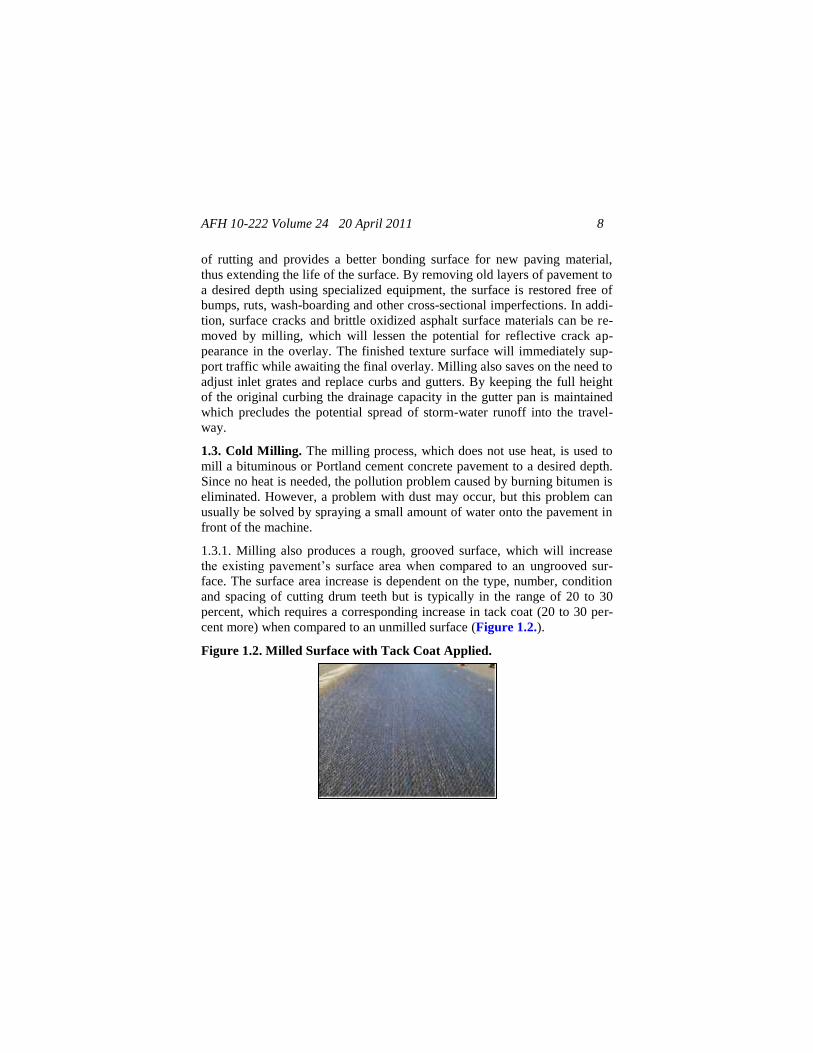
1.3.1. Milling also produces a rough, grooved surface, which will increase
the existing pavement’s surface area when compared to an ungrooved sur-
face. The surface area increase is dependent on the type, number, condition
and spacing of cutting drum teeth but is typically in the range of 20 to 30
percent, which requires a corresponding increase in tack coat (20 to 30 per-
cent more) when compared to an unmilled surface (Figure 1.2.).
Figure 1.2. Milled Surface with Tack Coat Applied.
AFH 10-222 Volume 24 20 April 2011 9
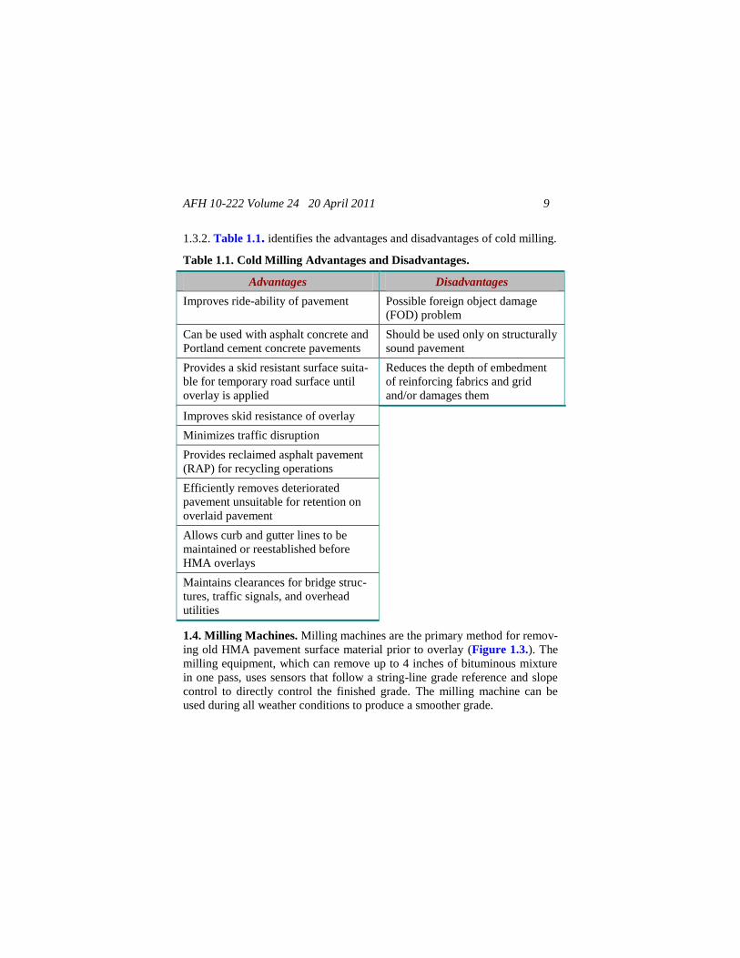
1.3.2. Table 1.1. identifies the advantages and disadvantages of cold milling.
Table 1.1. Cold Milling Advantages and Disadvantages.
Advantages Disadvantages
Improves ride-ability of pavement Possible foreign object damage
(FOD) problem
Can be used with asphalt concrete and
Portland cement concrete pavements
Should be used only on structurally
sound pavement
Provides a skid resistant surface suita-
ble for temporary road surface until
overlay is applied
Reduces the depth of embedment
of reinforcing fabrics and grid
and/or damages them
Improves skid resistance of overlay
Minimizes traffic disruption
Provides reclaimed asphalt pavement
(RAP) for recycling operations
Efficiently removes deteriorated
pavement unsuitable for retention on
overlaid pavement
Allows curb and gutter lines to be
maintained or reestablished before
HMA overlays
Maintains clearances for bridge struc-
tures, traffic signals, and overhead
utilities
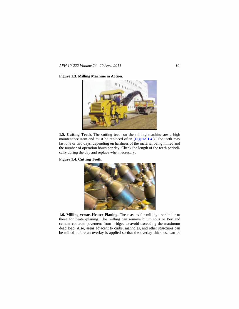
1.4. Milling Machines. Milling machines are the primary method for remov-
ing old HMA pavement surface material prior to overlay (Figure 1.3.). The
milling equipment, which can remove up to 4 inches of bituminous mixture
in one pass, uses sensors that follow a string-line grade reference and slope
control to directly control the finished grade. The milling machine can be
used during all weather conditions to produce a smoother grade.
AFH 10-222 Volume 24 20 April 2011 10
Figure 1.3. Milling Machine in Action.
1.5. Cutting Teeth. The cutting teeth on the milling machine are a high
maintenance item and must be replaced often (Figure 1.4.). The teeth may
last one or two days, depending on hardness of the material being milled and
the number of operation hours per day. Check the length of the teeth periodi-
cally during the day and replace when necessary.
Figure 1.4. Cutting Teeth.
1.6. Milling versus Heater-Planing. The reasons for milling are similar to
those for heater-planing. The milling can remove bituminous or Portland
cement concrete pavement from bridges to avoid exceeding the maximum
dead load. Also, areas adjacent to curbs, manholes, and other structures can
be milled before an overlay is applied so that the overlay thickness can be
AFH 10-222 Volume 24 20 April 2011 11
maintained adjacent to these structures. One advantage the pavement milling
machine has over the heater-planer is its ability to remove Portland cement
concrete pavement. This is particularly advantageous when milling a pave-
ment that has some Portland cement concrete along with the bituminous ma-
terial that must be planed or removed, such as in areas adjacent to manholes
or patches. The most extensive use of the milling machine is in pavement
recycling. The removed materials can be mixed with new aggregate and new
asphalt, per engineer’s mix design, to produce recycled cold mix or recycled
hot mix.
1.7. Milled Surface. Occasionally, when a pavement surface has been
milled, the surface is used as the riding surface for a period of time. For in-
stance, when a pavement does not have adequate skid resistance but no im-
mediate funds are available to overlay this pavement, one alternative is to
mill the surface to give it a rough surface texture and thereby provide ade-
quate skid resistance until it can be overlaid or otherwise repaired. An exces-
sive amount of material should not be removed because the pavement struc-
ture would be weakened. Raveling may become a problem with asphalt con-
crete pavements after the milling process; for that reason it is recommended
that the pavement be overlaid as soon after the milling as possible. On air-
fields, raveling could result in FOD to the aircraft. Therefore, an overlay
should be applied immediately after the milling operation is completed.
1.8. Milled Material. The material obtained from milling operations can be
used in pavement construction. The milled material can be stockpiled, but
care must be exercised not to stockpile it too high, especially in hot weather,
since the asphalt concrete material will have a tendency to bond thus making
it difficult to use. In most cases, the material should not be stockpiled over
10 feet. The milled material can be used for producing recycled cold mix,
recycled hot mix, and other mixes. Materials milled from different pavement
sections should be stored in separate homogeneous stockpiles rather than
conglomerate stockpiles. Homogeneous RAP sources are more consistent in
terms of asphalt binder and aggregate type and properties, and will lead to
improved consistency in mixture design and a better finished product. Milled
materials should be fractionated (separated/sieved) when used in RAP to
ensure proper mix design and production control.
AFH 10-222 Volume 24 20 April 2011 12
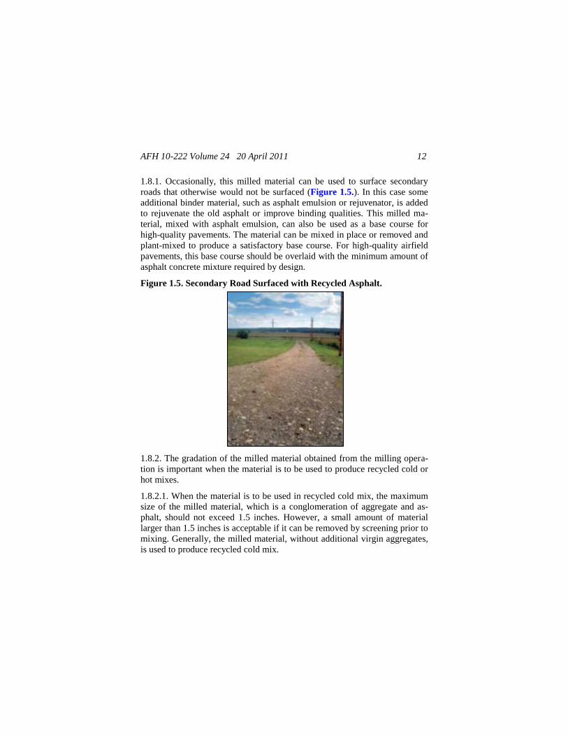
1.8.1. Occasionally, this milled material can be used to surface secondary
roads that otherwise would not be surfaced (Figure 1.5.). In this case some
additional binder material, such as asphalt emulsion or rejuvenator, is added
to rejuvenate the old asphalt or improve binding qualities. This milled ma-
terial, mixed with asphalt emulsion, can also be used as a base course for
high-quality pavements. The material can be mixed in place or removed and
plant-mixed to produce a satisfactory base course. For high-quality airfield
pavements, this base course should be overlaid with the minimum amount of
asphalt concrete mixture required by design.
Figure 1.5. Secondary Road Surfaced with Recycled Asphalt.
1.8.2. The gradation of the milled material obtained from the milling opera-
tion is important when the material is to be used to produce recycled cold or
hot mixes.
1.8.2.1. When the material is to be used in recycled cold mix, the maximum
size of the milled material, which is a conglomeration of aggregate and as-
phalt, should not exceed 1.5 inches. However, a small amount of material
larger than 1.5 inches is acceptable if it can be removed by screening prior to
mixing. Generally, the milled material, without additional virgin aggregates,
is used to produce recycled cold mix.
AFH 10-222 Volume 24 20 April 2011 13
1.8.2.2. When the milled material is to be used in recycled hot mix, the gra-
dation of the milled material after extraction of the asphalt cement is impor-
tant. Very little breakdown of the aggregate should occur during the milling
operation. It is important that the maximum size of the material as milled
does not exceed 1.5 to 2 inches to ensure that it will break up and satisfacto-
rily mix with the new materials in the production of recycled hot mix.
1.8.2.3. Some filler material passing the No.200 sieve will be manufactured
during the milling operation. Depending on the aggregate type, 1 to 3 percent
additional filler may be manufactured. One of the problems in designing a
recycled mixture is not to exceed the maximum amount of filler allowed.
Generally, new aggregates that are to be added to a recycled mixture are re-
quired to have little or no filler. Therefore, washing of new aggregate is of-
ten required to remove the filler prior to producing the recycled mixture.
1.9. Base Course. When the asphalt pavement material is to be removed
down to the base course, care should be taken to prevent damage to the base
course. Any damage to the base course should be corrected prior to placing
the recycled mixture. Generally, approximately 0.5 inch of asphalt mixture
should be left in place to prevent damage to the base course by the milling
equipment or by rain.
1.10. Reinforcing Fabric. When a paving fabric or grid is known to exist in
the underlying pavement structure that is being milled, either leave the fabric
or grid in place and mill no closer to the fabric or grid than a distance equal
to the top size of the in place aggregate (typically .5 to .75 inches), or com-
pletely remove the fabric or grid. In the latter case, the type of fabric or grid
used will be important, as many of the existing textiles and steel netting rein-
forcement layers will pose problems to the milling operation. In some cases,
reversing the normal rotational direction of the drum will lead to improved
results. The manufacturer of the reinforcement or grid product, if known,
should be consulted prior to milling.
AFH 10-222 Volume 24 20 April 2011 14
Chapter 2
MILLING MACHINE SPECIFICATIONS
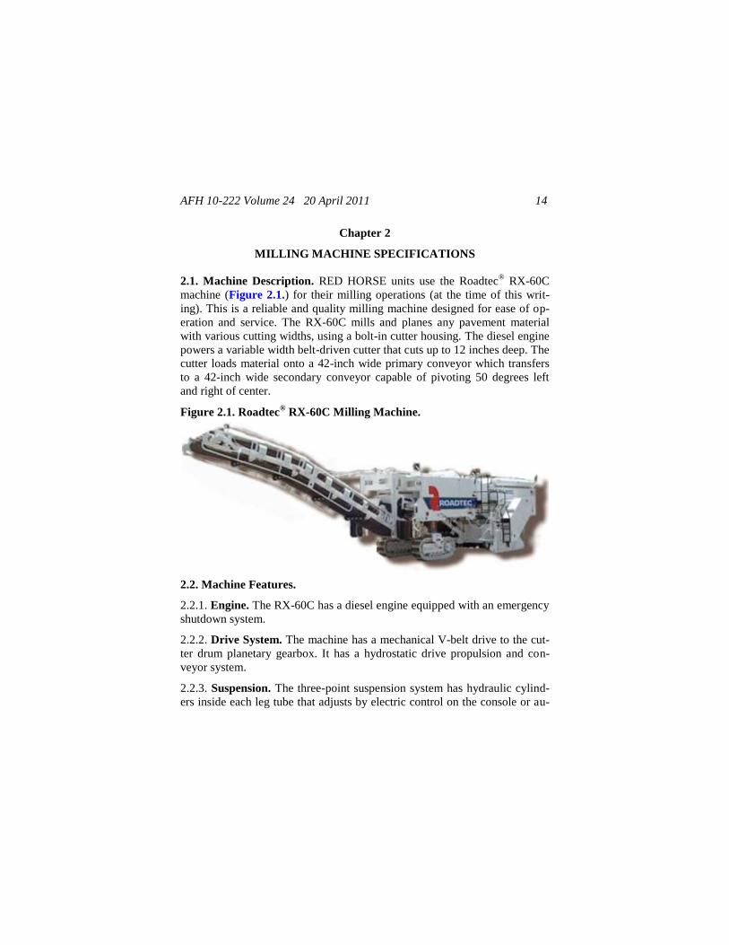
2.1. Machine Description. RED HORSE units use the Roadtec® RX-60C
machine (Figure 2.1.) for their milling operations (at the time of this writ-
ing). This is a reliable and quality milling machine designed for ease of op-
eration and service. The RX-60C mills and planes any pavement material
with various cutting widths, using a bolt-in cutter housing. The diesel engine
powers a variable width belt-driven cutter that cuts up to 12 inches deep. The
cutter loads material onto a 42-inch wide primary conveyor which transfers
to a 42-inch wide secondary conveyor capable of pivoting 50 degrees left
and right of center.
Figure 2.1. Roadtec® RX-60C Milling Machine.
2.2. Machine Features.
2.2.1. Engine. The RX-60C has a diesel engine equipped with an emergency
shutdown system.
2.2.2. Drive System. The machine has a mechanical V-belt drive to the cut-
ter drum planetary gearbox. It has a hydrostatic drive propulsion and con-
veyor system.
2.2.3. Suspension. The three-point suspension system has hydraulic cylind-
ers inside each leg tube that adjusts by electric control on the console or au-

AFH 10-222 Volume 24 20 April 2011 15
tomatically by the use of grade controls (see paragraphs 2.2.7. and 2.2.10.2.
below).
2.2.4. Steering. The machine has a 10-foot 3-inch turning radius with three
track steering or 34-foot 4-inch turning radius with two track steering. An
automatic rear-centering device aligns the rear track and a red pointer indi-
cates the rear position. All three tracks steering provides crab steering with
coordinated steering system.
2.2.5. Water. Spray bars located on the front and back of the cutter housing
and on both primary and secondary conveyors provide cooling water to the
cutter drum. Water is provided for wash-down by use of the wash-down
hose. The wash-down hose is stored on the hose reel at the front of the ma-
chine.
2.2.6. Conveyor. The conveyors are two-piece front discharge type with a
42-inch wide pick-up (primary) and 42-inch load-out (secondary) conveyor
with endless cleated belts. The load-out conveyor swings 50-degrees to ei-
ther side.
2.2.7. Grade Controls. Grade controls can be adjusted manually from the
console, or the grade control systems on each side of the machine can auto-
matically maintain the desired depth of cut to 12-inches. A valve on either
side allows the grade controls to be activated from ground level.
2.2.8. Cutter Drum. Cutter drums have multiple cutting widths with a bolt-
in cutter housing (Figure 2.2.). Drums come in widths of 7-foot 2-inches, 8-
foot 2-inches, 10-foot, and 12-foot 6-inches. The 46-inch tip-to-tip diameter
quick change tooth cutter drum rotates at 94.7 revolutions per minute (RPM)
at full throttle. The cutter drum is turned by a belt-driven planetary gearbox.
2.2.9. Safety Features. The control panel and electronic instrumentation has
been designed for simplicity, yet provides adequate and visually displayed
information for the operator to be continually aware of machine operation
and system conditions.
2.2.9.1. The engine will start only when prestart conditions are met.
AFH 10-222 Volume 24 20 April 2011 16
Figure 2.2. Cutter Drum.
2.2.9.2. The engine will not start with the machine in an unsafe condition.
2.2.9.3. The engine will not run when water overheats or oil pressure is low.
2.2.9.4. The cutter drum stops when a hard, unmillable object is encountered.
This will cause the machine to jump upwards and backwards and can be very
hazardous to the ground crew.
2.2.10. Optional Equipment:
2.2.10.1. Electronic grade jacks;
2.2.10.2. Electronic grade controls;
2.2.10.2.1. Grad-Line slope Control System. The grad-line slope control
system is a complete, non-contacting slope control system (Figure 2.3.). The
system includes the following hardware: one control module, one handset,
and a carrying case.
2.2.10.2.2. TOPCON Grade/Slope Systems. The TOPCON Grade/Slope
System is a complete, non-contacting control system, which combines both
elevation control and slope control into one package (Figure 2.4.). The
TOPCON system includes the following hardware: two control boxes, two
sonic trackers, two remote jog switches, two junction boxes and a single
slope sensor.

AFH 10-222 Volume 24 20 April 2011 17
Figure 2.3. Grad-Line Control Module and Handset.
Figure 2.4. TOPCON Grade/Slope Control Box.
2.2.10.3. Feet or meter per minute indicator;
2.2.10.4. Operator’s seat;
2.2.10.5. Operator’s canopy; and
2.2.10.6. Rear console travel controls.
2.3. Component Nomenclature. See Figure 2.5. for component nomencla-
ture.
AFH 10-222 Volume 24 20 April 2011 18
Figure 2.5. Component Nomenclature.
2.4. Machine Specifications. See Figure 2.6. and Table 2.1. for machine
dimensions.
Figure 2.6. Machine Dimensions.
AFH 10-222 Volume 24 20 April 2011 19
Table 2.1. Dimensions.
Milling Machine Dimensions
Overall length (conveyor up) 50’ – 4-1/2‖
Overall height 14’ – 4‖
Wheel base 17’ – 9‖
Outside to outside tracks 25’ – 2‖
Width (with cutter drum) 8’ – 5-1/2‖
Length without conveyor 30’ – 4-1/2‖
Shipping height 11’ – 3-1/2‖
2.4.1. Engine. The RX-60C diesel engine is a Caterpillar 3412, 900 horse
power (hp) (671 kW) @ 2,100 RPM equipped with an emergency shutdown
system. An optional Cummins QSK-19C, 800 hp (596 kW) @ 2,100 RPM
with an emergency shutdown system is also available.
2.4.2. Main Drive System. A three speed hydrostatic motor.
2.4.3. Speed Ranges. The machine has three operating ranges:
2.4.3.1. Operating range: 0 – 120 feet per minute.
2.4.3.2. High operating range: 0 – 155 feet per minute.
2.4.3.3. Travel range: 0 – 3.5 miles per hour.
2.4.4. Weights (dry). The basic machine weight with the 86-inch drum is
78,000 pounds. The maximum operating weight, with the 150-inch drum, is
91,920 pounds.
2.4.5. Service Capacity. See Table 2.2. for service capacities.
AFH 10-222 Volume 24 20 April 2011 20
Table 2.2. Service Capacity.
System Capacity
Fuel 412 gallons
Water 1,200 gallons
Hydraulic *100 gallons at 100% capacity
*90 gallons at 90% capacity
Cooling 42 gallons
Air Compressor 120 gallons
*Tank fluid capacity of 90% is the recommended amount of hydraulic oil to fill the
hydraulic oil tank. If filled to 100%, tank would overflow due to fluid expansion when
hydraulic oil becomes hot.
2.5. Safety Precautions. Observe the ―PRECAUTION‖ boxes below; they
are found throughout this manual. These boxes are used to draw attention to
important information that affects safe unit operation or the safety of person-
nel. They mean ATTENTION! – BE ALERT! – YOUR SAFETY IS IN-
VOLVED!
NOTE!
Highlights an essential operating or maintenance procedure, condi-
tion, or statement.
CAUTION!
Highlights an essential operating or maintenance procedure, practice,
condition, statement, etc., which, if not strictly observed, could result
in damage to, or destruction of, equipment or loss of mission effec-
tiveness.
WARNING!
Highlights and essential operating or maintenance procedure, prac-
tice, condition, statement, etc., which, if not strictly observed, could
result in injury to, or death of, personnel or long term health hazards.
AFH 10-222 Volume 24 20 April 2011 21
2.5.1. Preliminary Safety and Operating Instructions. Adhere to the fol-
lowing instructions:
2.5.1.1. Read and study the milling machine safety manual provided in the
literature package furnished with the machine. ―FOLLOW ALL SAFETY
PRECAUTIONS.‖
2.5.1.2. Read the operating section of the manufacturer’s Operations, Ser-
vice, & Maintenance Manual thoroughly.
2.5.1.3. Read and study the service section of the manufacturer’s Operation,
Service, & Maintenance Manual.
2.5.1.4. Operator’s platform is for properly trained and qualified personnel
only. One operator only is allowed on the platform… ―NO RIDERS!‖
2.5.1.5. Never fuel the unit with the engine running, when smoking, or near
an open flame.
2.5.1.6. Perform a walk-around visual inspection for signs of fluid leakage or
component wear and sign off on the AF Form 1800, Operator’s Inspection
Guide and Trouble Report, before operating unit.
2.5.1.7. Before starting unit or when stopping unit, always set parking brake,
put travel and conveyor controls in neutral and disengage cutter drum clutch.
2.5.2. Operational Precautions. Adhere to the following instructions:
2.5.2.1. Pretest steering, brakes, and all other controls.
2.5.2.2. Use caution on uneven surfaces and rough terrain.
2.5.2.3. Never climb on or off the unit when the unit is moving and always
use proper steps and rails when climbing on or off the unit.
2.5.2.4. Look in all directions and use spotters before reversing the unit.
2.5.2.5. Be aware of all clearance and ground obstacles.
2.5.3. Maintenance Precautions. Adhere to the following instructions:
AFH 10-222 Volume 24 20 April 2011 22
2.5.3.1. Always shut off the engine, raise the moldboard with the power
pack, and set the safety bars when working on the cutter drum, conveyor or
otherwise servicing the machine.
2.5.3.2. Keep control plates on console clean and replace lost or damaged
decals immediately.
2.5.3.3. Block tracks and insert safety bars before servicing the machine.
2.5.3.4. Turn the battery disconnect to ―OFF‖ when servicing the electrical
system or when doing any welding on the machine.
2.5.3.5. Use only approved or recommended fluids and filters.
2.5.3.6. Do not modify this machine in any way that will affect safety.
2.6. Detailed Systems Description.
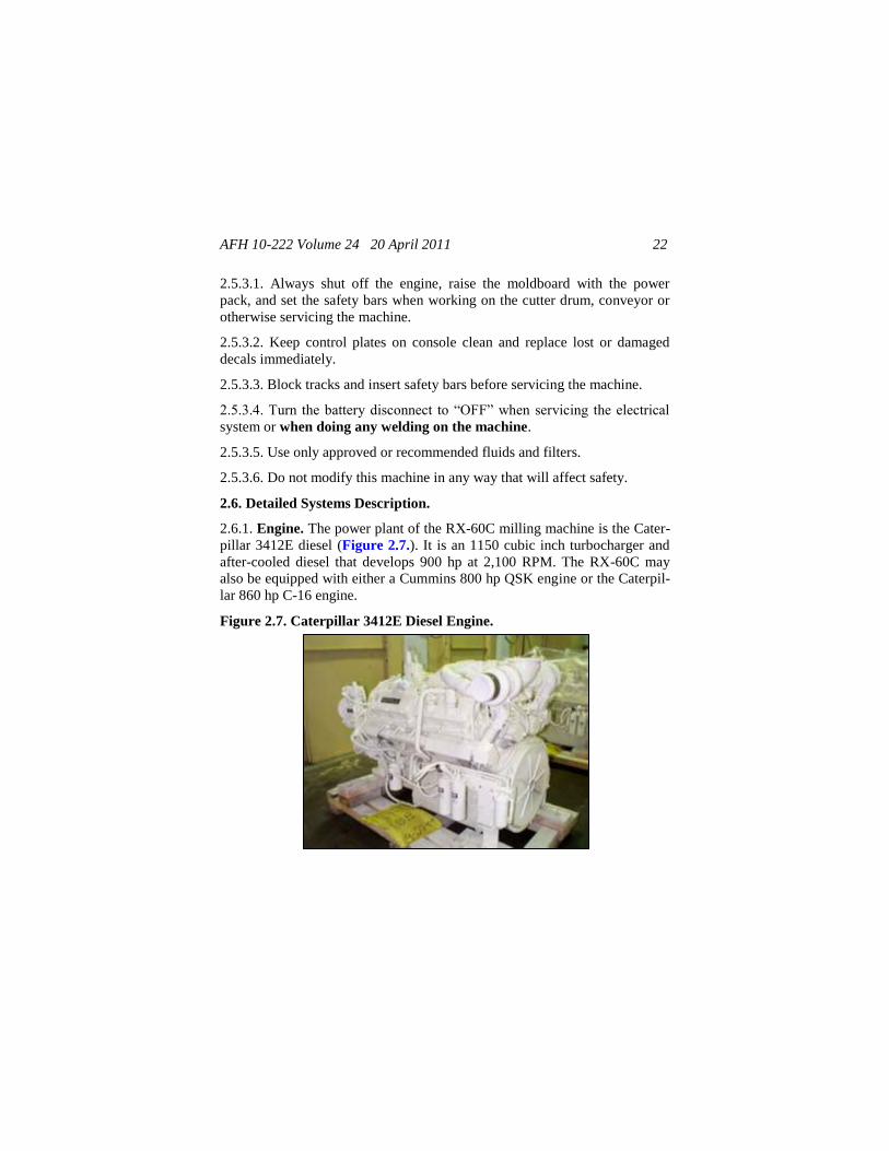
2.6.1. Engine. The power plant of the RX-60C milling machine is the Cater-
pillar 3412E diesel (Figure 2.7.). It is an 1150 cubic inch turbocharger and
after-cooled diesel that develops 900 hp at 2,100 RPM. The RX-60C may
also be equipped with either a Cummins 800 hp QSK engine or the Caterpil-
lar 860 hp C-16 engine.
Figure 2.7. Caterpillar 3412E Diesel Engine.
AFH 10-222 Volume 24 20 April 2011 23
2.6.1.1. The turbocharger uses exhaust gas energy to pack more air into the
cylinders for efficient combustion, improved fuel consumption, and reduced
heat. The turbocharger also compensates to maintain combustion air density
for operating at higher altitudes. The engine will deliver full rated power to
8,500 feet above sea level.
2.6.1.2. The after-cooler cools the pressurized intake air from the turbo-
charger permitting greater air density and more complete combustion of fuel.
2.6.1.3. The engine is equipped with an electronic control module (ECM)
that is connected to many sensors on the engine. These sensors provide vital
information to the ECM for proper monitoring of engine functions. High
coolant temperature or low oil pressure will activate sensors that open the
circuit to the fuel injector solenoid, shutting off fuel supply to the engine.
2.6.1.4. The engine data plate shows the engine’s serial number (ESN), con-
trol parts list (CPL), model, and the horsepower and RPM rating. This in-
formation is used when ordering parts and for service needs.
2.6.1.5. Fuel. Always use reputable grade of diesel fuel that has sulfur con-
tent below 0.5%; higher sulfur contents affect oil change intervals. Observe
strict cleanliness when filling tank. At low ambient temperatures, use winter-
grade fuel only. The fuel must be replenished promptly to prevent the tank
from running dry, otherwise fuel filter and injection lines will need air-
venting.
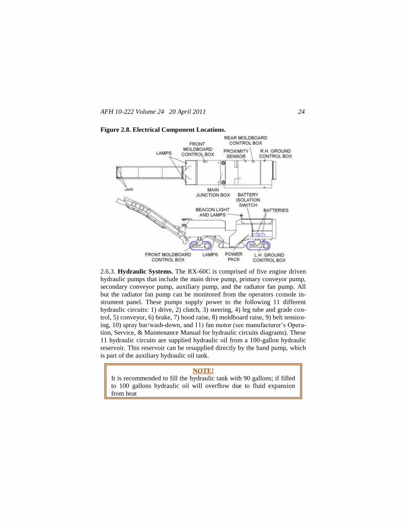
2.6.2. Electrical System. Two 12-volt batteries connected in series provide
for a 24 volt electrical system. The batteries are the center of the electrical
system and proper care will ensure trouble-free operation. A 60 amp, 24 volt
alternator provides current to maintain battery charge and provides power to
operate the electrical system. See Figure 2.8. to locate electrical compo-
nents.
NOTE!
The engine data plate must not be changed unless approved by Ca-
terpillar Engine Company, Inc.
AFH 10-222 Volume 24 20 April 2011 24
Figure 2.8. Electrical Component Locations.
2.6.3. Hydraulic Systems. The RX-60C is comprised of five engine driven
hydraulic pumps that include the main drive pump, primary conveyor pump,
secondary conveyor pump, auxiliary pump, and the radiator fan pump. All
but the radiator fan pump can be monitored from the operators console in-
strument panel. These pumps supply power to the following 11 different
hydraulic circuits: 1) drive, 2) clutch, 3) steering, 4) leg tube and grade con-
trol, 5) conveyor, 6) brake, 7) hood raise, 8) moldboard raise, 9) belt tension-
ing, 10) spray bar/wash-down, and 11) fan motor (see manufacturer’s Opera-
tion, Service, & Maintenance Manual for hydraulic circuits diagrams). These
11 hydraulic circuits are supplied hydraulic oil from a 100-gallon hydraulic
reservoir. This reservoir can be resupplied directly by the hand pump, which
is part of the auxiliary hydraulic oil tank.
NOTE!
It is recommended to fill the hydraulic tank with 90 gallons; if filled
to 100 gallons hydraulic oil will overflow due to fluid expansion
from heat

AFH 10-222 Volume 24 20 April 2011 25
2.7. Aircraft Load Plan. Contact your unit’s air transportation representa-
tive or the Air Transportability Test Loading Activity (ATTLA) for air
transport information at:
ASC/ENFC
2530 Loop Road West
WPAFB, OH 45433-7101
https://afkm.wpafb.af.mil/ATTLA (direct)
https://wwwd.my.af.mil/afknprod/ATTLA (AF Portal)
RX-60 Milling Machine Internal Air Transport Certification POC:
DSN 785-2547 or commercial (937) 255-2547
Refer to file number 4.K.14 to reference this item.
AFH 10-222 Volume 24 20 April 2011 26
Chapter 3
MILLING MACHINE OPERATING
AND MAINTENANCE PROCEDURES
3.1. Machine Familiarization. Before operating the RX-60C for the first
time, carefully read and understand the manufacturer’s Operation, Service,
and Maintenance Manual (Part Number 200501); familiarizing yourself with
the machine, its systems, and controls. Read and study the milling machine
safety manual provided in the literature package that comes with the ma-
chine. Follow all safety precautions!
3.2. Pre-start Procedures. Perform the following tasks prior to starting the
machine.
3.2.1. Check machine fluid levels:
3.2.1.1. Check engine oil level at the front of the engine.
3.2.1.2. Check hydraulic fluid level via the two sight glasses at the rear of the
machine. When cold, the level should be near the top of the bottom sight
glass. When hot, level of oil should always be visible in the upper levels of
the top viewing gauge. If low, open the door beneath the sight glasses and
turn the crank on the slave tank until reaching the correct level in the top
sight glass.
3.2.1.3. Check the radiator coolant on the top rear of the machine.
3.2.1.4. Check the water tank level.
3.2.1.5. Check the oil level in the Durst pump drive inside the rear door on
the right side of the machine. Ensure oil is between 1 and 2 on the yellow-
topped dipstick.
3.2.2. Inspect water filter and spray nozzles.
WARNING!
Operator’s platform is for properly trained and qualified personnel
only. One operator on platform—NO RIDERS!
AFH 10-222 Volume 24 20 April 2011 27
3.2.3. Using AF Form 1800, perform a 360 degree walk-around visual in-
spection for signs of fluid leaks or component wear. Visually inspect high-
wear components such as cutter teeth, engine belts, and conveyor belts. En-
sure conveyor belts are not rubbing against anything. When complete, sign
off the AF Form 1800 and report any discrepancies to maintenance activity.
3.2.4. Observe all safety decals.
3.2.5. Upon entering operator’s station, latch safety chains located on both
sides of station.
3.3. Starting the Engine. Follow the instructions below for engine starting
procedures.
3.3.1. Place the throttle control at low idle.
3.3.2. Place travel control in neutral and conveyor selector switch to off.
3.3.3. Disengage clutch knob down. Apply brake knob down.
3.3.4. Left and right grade sensors should be off. Moldboard should be in the
down position.
3.3.5. Push the ignition switch down and right to ―start.‖ Once the engine
starts and the light goes out allow the switch to return to the ―on‖ position.
NOTE!
Neutral safety switches will prevent the engine from starting unless
the travel in neutral, conveyors off, clutch off and moldboard in the
down position.
CAUTION!
Become familiar with the operator’s console’s component locations,
descriptions, and functions at home station before operating this ma-
chine. Do not wait until it is time to conduct actual milling opera-
tions in the field. See the manufacturer’s Operation, Service & Main-
tenance manual for full description and component location.
AFH 10-222 Volume 24 20 April 2011 28
3.4. Machine Operation. Perform the following steps to operate the ma-
chine.
3.4.1. After the engine has warmed for 15 to 20 minutes (allow 30 minutes
when ambient temperature is colder than 30 degrees Fahrenheit), start the
conveyor belts at low idle by selecting forward on the conveyor switch in the
center, top portion of the operator’s console. Descend from the operator’s
platform and listen for noisy bearings. Replace any noisy bearings before
starting milling operations.
3.4.2. Return to the operator’s platform and increase throttle to full speed
and check the following controls and pressures:
3.4.2.1. Tachometer at 2,100 RPM.
3.4.2.2. Auxiliary system pressure at 2,700 pounds per square inch (PSI).
3.4.2.3. Clutch pressure at 0 PSI.
3.4.2.4. Feed conveyor pressure at 300 PSI.
3.4.2.5. Discharge conveyor pressure at 300 PSI.
3.4.2.6. Travel pressure at 300 PSI.
3.4.3. Position the machine at the beginning of the cut. It may be best to start
cutting a few feet into the cut zone to prevent the possibility of cutting
CAUTION!
Run conveyors for no more than 30 seconds without water spray.
The primary belt beneath the machine gets very hot.
NOTE!
For cold weather start-up, refer to the specifications section in the
specific engine manufacturer’s handbook before leaving home sta-
tion. Do not wait until it becomes cold and on the job site before
learning this procedure.
AFH 10-222 Volume 24 20 April 2011 29
pavement before the starting point. The area left can be trimmed later on the
clean up cuts.
3.4.4. Zero out the grade control sensors.
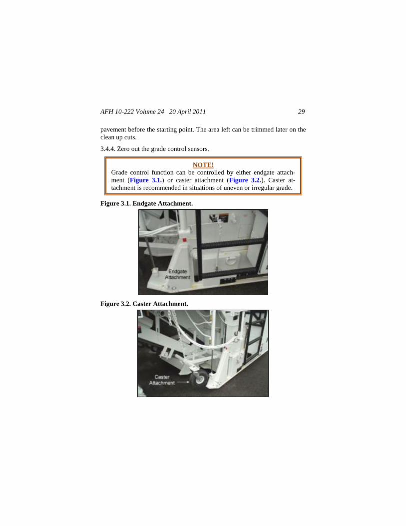
Figure 3.1. Endgate Attachment.
Figure 3.2. Caster Attachment.
NOTE!
Grade control function can be controlled by either endgate attach-
ment (Figure 3.1.) or caster attachment (Figure 3.2.). Caster at-
tachment is recommended in situations of uneven or irregular grade.
AFH 10-222 Volume 24 20 April 2011 30
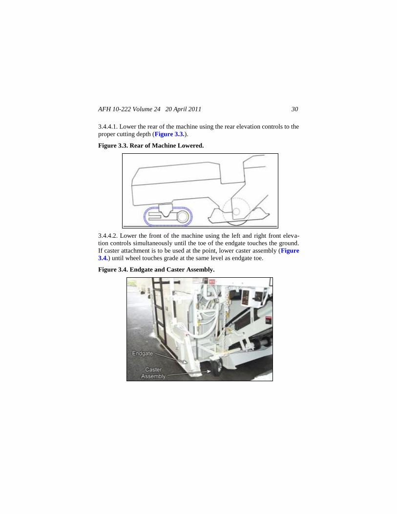
3.4.4.1. Lower the rear of the machine using the rear elevation controls to the
proper cutting depth (Figure 3.3.).
Figure 3.3. Rear of Machine Lowered.
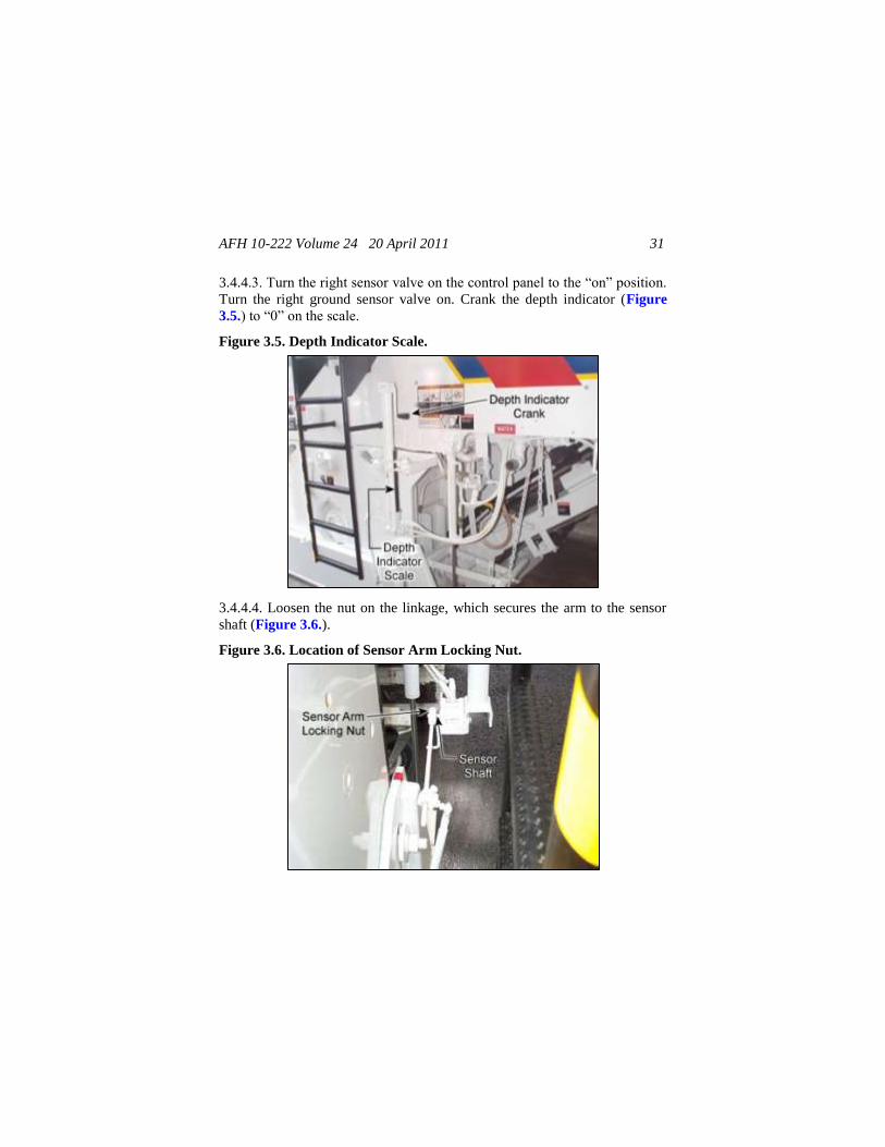
3.4.4.2. Lower the front of the machine using the left and right front eleva-
tion controls simultaneously until the toe of the endgate touches the ground.
If caster attachment is to be used at the point, lower caster assembly (Figure
3.4.) until wheel touches grade at the same level as endgate toe.
Figure 3.4. Endgate and Caster Assembly.
AFH 10-222 Volume 24 20 April 2011 31
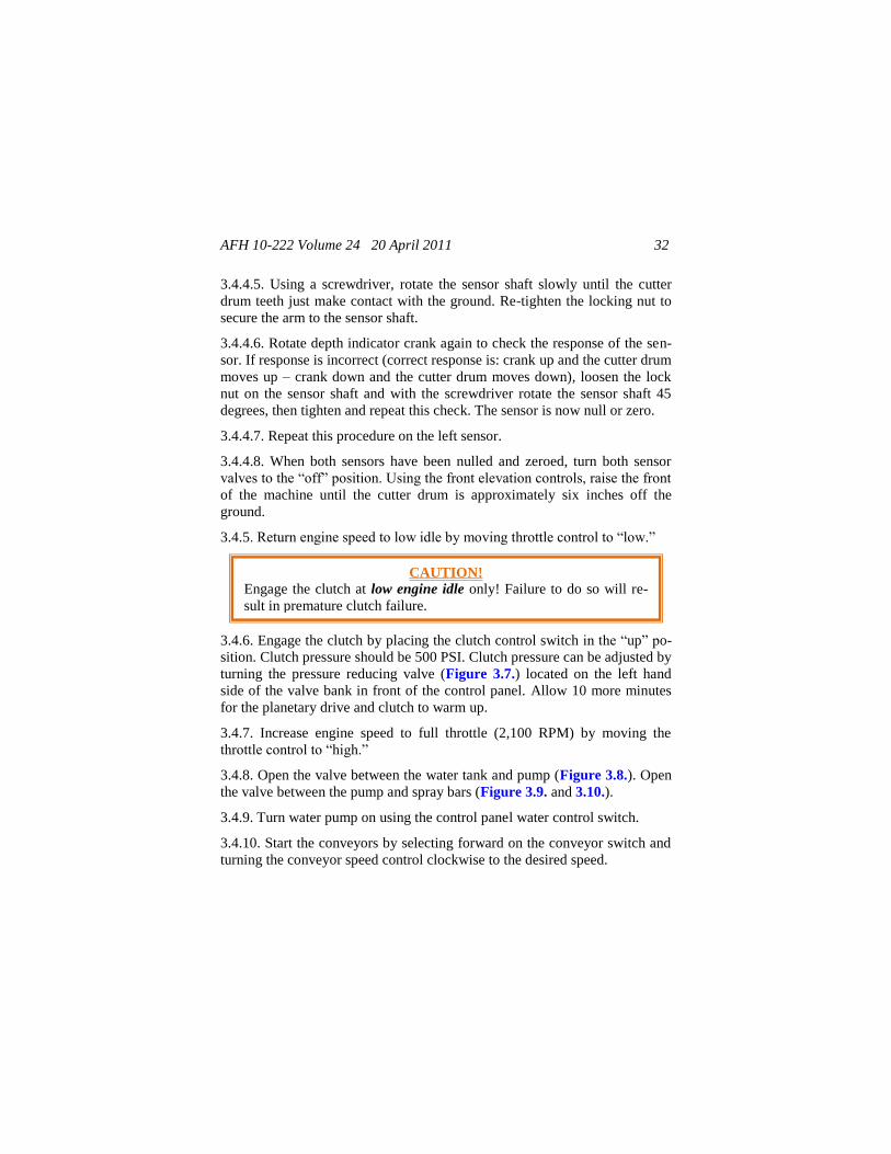
3.4.4.3. Turn the right sensor valve on the control panel to the ―on‖ position.
Turn the right ground sensor valve on. Crank the depth indicator (Figure
3.5.) to ―0‖ on the scale.
Figure 3.5. Depth Indicator Scale.
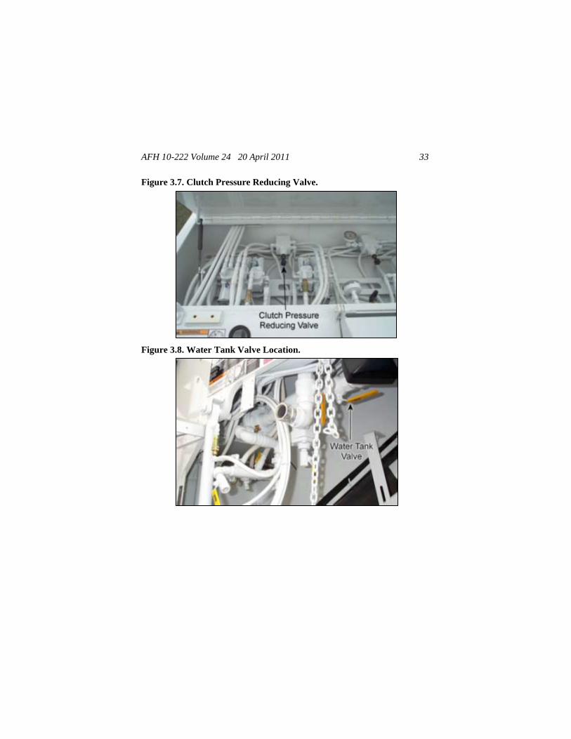
3.4.4.4. Loosen the nut on the linkage, which secures the arm to the sensor
shaft (Figure 3.6.).
Figure 3.6. Location of Sensor Arm Locking Nut.
AFH 10-222 Volume 24 20 April 2011 32
3.4.4.5. Using a screwdriver, rotate the sensor shaft slowly until the cutter
drum teeth just make contact with the ground. Re-tighten the locking nut to
secure the arm to the sensor shaft.
3.4.4.6. Rotate depth indicator crank again to check the response of the sen-
sor. If response is incorrect (correct response is: crank up and the cutter drum
moves up – crank down and the cutter drum moves down), loosen the lock
nut on the sensor shaft and with the screwdriver rotate the sensor shaft 45
degrees, then tighten and repeat this check. The sensor is now null or zero.
3.4.4.7. Repeat this procedure on the left sensor.
3.4.4.8. When both sensors have been nulled and zeroed, turn both sensor
valves to the ―off‖ position. Using the front elevation controls, raise the front
of the machine until the cutter drum is approximately six inches off the
ground.
3.4.5. Return engine speed to low idle by moving throttle control to ―low.‖
3.4.6. Engage the clutch by placing the clutch control switch in the ―up‖ po-
sition. Clutch pressure should be 500 PSI. Clutch pressure can be adjusted by
turning the pressure reducing valve (Figure 3.7.) located on the left hand
side of the valve bank in front of the control panel. Allow 10 more minutes
for the planetary drive and clutch to warm up.
3.4.7. Increase engine speed to full throttle (2,100 RPM) by moving the
throttle control to ―high.‖
3.4.8. Open the valve between the water tank and pump (Figure 3.8.). Open
the valve between the pump and spray bars (Figure 3.9. and 3.10.).
3.4.9. Turn water pump on using the control panel water control switch.
3.4.10. Start the conveyors by selecting forward on the conveyor switch and
turning the conveyor speed control clockwise to the desired speed.
CAUTION!
Engage the clutch at low engine idle only! Failure to do so will re-
sult in premature clutch failure.
AFH 10-222 Volume 24 20 April 2011 33
Figure 3.7. Clutch Pressure Reducing Valve.
Figure 3.8. Water Tank Valve Location.
AFH 10-222 Volume 24 20 April 2011 34
Figure 3.9. Location of Drum Spray Bar Valves.
Figure 3.10. Primary and Secondary Conveyor Spray Bars.
3.4.11. Turn the left and right sensor controls located on the control panel to
the ―on‖ position and turn both ground controls on (Figure 3.11.).
AFH 10-222 Volume 24 20 April 2011 35
Figure 3.11. Ground Control Location.
3.4.12. Crank the grade control depth indicator to read the required depth of
the cut on each side of the machine. Machine will slowly lower itself into the
cut.
3.4.13. Lower the moldboard by pushing the moldboard toggle switch on the
control panel ―down.‖ Moldboard down pressure can be adjusted by turning
the pressure reducing valve located underneath the left hand side of the con-
trol panel. The normal operating pressure of the moldboard pressure valve is
150 PSI (Figure 3.12.).
Figure 3.12. Rear Moldboard Pressure Reducing Valve Location.
AFH 10-222 Volume 24 20 April 2011 36
3.4.14. Release the brake by pushing control panel switch upward.
3.4.15. Place the travel control valve in the slow range. Ease the travel speed
joystick slowly forward starting the cutting process very slowly (approx-
imately 10-15 feet per minute) until the rear leg gets into the cut. At this
point, the travel rate can be increased to the desired speed, typically around
50 feet per minute based on a 2 inch cutting depth in asphalt. Do not attempt
to cut concrete at this speed.
3.4.16. On the second and subsequent passes, the grade controls on the side
of the machine that is next to the cut previously made will have to be set at
zero. Leaving controls set at 2 inches will result in cutting another 2 inches.
3.4.17. Constantly monitor all gauges during operation. Pay particular atten-
tion to the following:
3.4.17.1. Track Pressure. This gauge identifies how hard the machine is
pushing against the cut. Keep this pressure under 4,000 PSI.
3.4.17.2. Primary and Secondary Conveyor Belt Pressures. When the
conveyor belts become overloaded, they will stop rotating at approximately
4,000 PSI. Decreasing the angle of the secondary conveyor may allow the
belt to start rotating again. If that does not work, remove some material from
the conveyor with a shovel until the conveyor starts rotating again. When
milling operations resume, slow down the rate of cut.
3.4.18. Sometimes the moldboard will hang up when trying to get down into
the cut. If the machine fails to proceed when easing into a cut, check the
track pressure gauge. If the pressure is very high, bump the rear moldboard
switch up and put it right back down again. If that fails to work, ensure the
range selector is in the slow setting. If not, return the travel lever to the
―stop‖ position before changing the setting to the slow setting and then re-
turn the travel lever to the ―on‖ position.
CAUTION!
If the conveyor belts stop from overpressure (~4,000 PSI), shut off
conveyors immediately! Failure to do so may result in a pressure line
rupturing or damage to the hydraulic motor.
AFH 10-222 Volume 24 20 April 2011 37
3.5. Stopping and Shutdown.
3.5.1. To stop machine travel, return the travel control joystick to the ―neu-
tral‖ position.
3.5.2. Apply the brake.
3.5.3. Turn water pump off.
3.5.4. Turn both the left and right sensor valves to the ―off‖ position.
3.5.5. Raise the front and rear elevation of the machine using the electric
toggle switches.
3.5.6. Place the throttle control in the low idle position and permit the engine
to idle for a short period to cool down.
3.5.7. Disengage the clutch by flipping the toggle switch down.
3.5.8. Return the conveyor selector control to ―off.‖
3.5.9. Raise the moldboard by pushing the moldboard toggle switch up.
3.5.10. Close the water valve between the pump and spray bars.
3.5.11. Turn the ignition switch to ―off.‖
3.6. Interchangeable Cutter Housing Procedure. The RX-60C gives the
user the option of several different cutting widths ranging from 7 foot-2
inches to 12 foot-6inches. This application requires a removable cutter hous-
ing, which can be exchanged from under the machine to facilitate the desired
width. The following is a visual overview illustrating the changeability of the
RX-60C cutter housings.
3.6.1. Endgate Removal. Perform the following procedures only if replace-
ment cutter-housing is equipped with endgates.
WARNING!
Always shut off the engine, raise the moldboard with the power pack
and set the safety bars when working on the cutter drum, conveyor
or otherwise servicing the machine.
AFH 10-222 Volume 24 20 April 2011 38
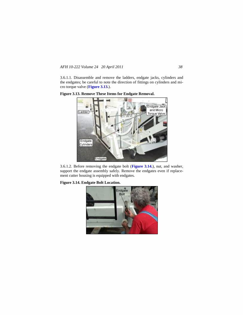
3.6.1.1. Disassemble and remove the ladders, endgate jacks, cylinders and
the endgates; be careful to note the direction of fittings on cylinders and mi-
cro torque valve (Figure 3.13.).
Figure 3.13. Remove These Items for Endgate Removal.
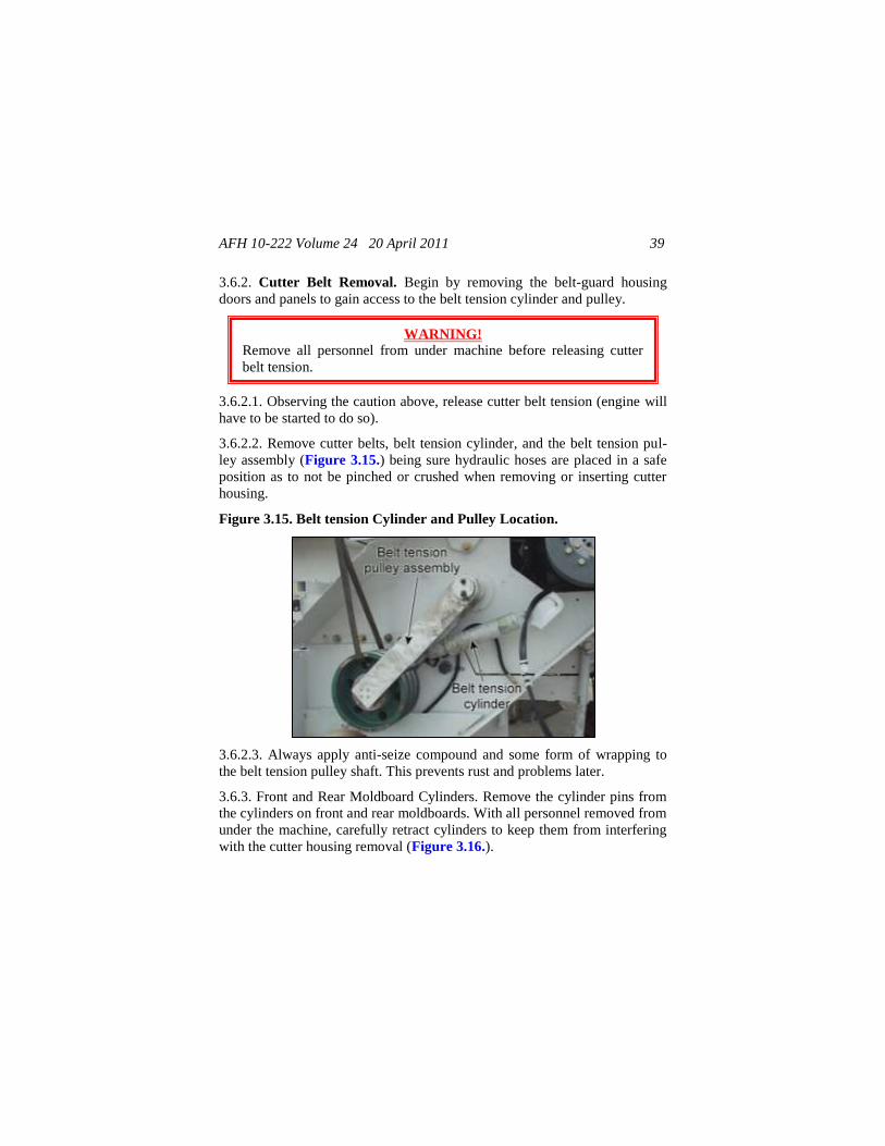
3.6.1.2. Before removing the endgate bolt (Figure 3.14.), nut, and washer,
support the endgate assembly safely. Remove the endgates even if replace-
ment cutter housing is equipped with endgates.
Figure 3.14. Endgate Bolt Location.
AFH 10-222 Volume 24 20 April 2011 39
3.6.2. Cutter Belt Removal. Begin by removing the belt-guard housing
doors and panels to gain access to the belt tension cylinder and pulley.
3.6.2.1. Observing the caution above, release cutter belt tension (engine will
have to be started to do so).
3.6.2.2. Remove cutter belts, belt tension cylinder, and the belt tension pul-
ley assembly (Figure 3.15.) being sure hydraulic hoses are placed in a safe
position as to not be pinched or crushed when removing or inserting cutter
housing.
Figure 3.15. Belt tension Cylinder and Pulley Location.
3.6.2.3. Always apply anti-seize compound and some form of wrapping to
the belt tension pulley shaft. This prevents rust and problems later.
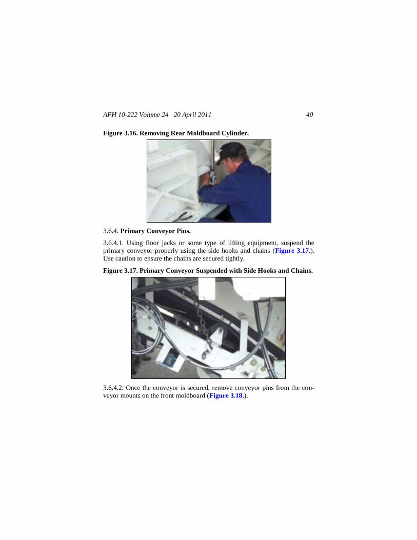
3.6.3. Front and Rear Moldboard Cylinders. Remove the cylinder pins from
the cylinders on front and rear moldboards. With all personnel removed from
under the machine, carefully retract cylinders to keep them from interfering
with the cutter housing removal (Figure 3.16.).
WARNING!
Remove all personnel from under machine before releasing cutter
belt tension.
or otherwise servicing the machine.
AFH 10-222 Volume 24 20 April 2011 40
Figure 3.16. Removing Rear Moldboard Cylinder.
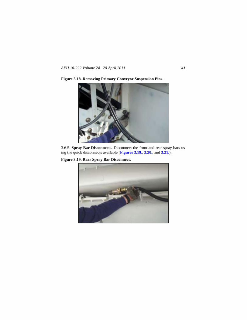
3.6.4. Primary Conveyor Pins.
3.6.4.1. Using floor jacks or some type of lifting equipment, suspend the
primary conveyor properly using the side hooks and chains (Figure 3.17.).
Use caution to ensure the chains are secured tightly.
Figure 3.17. Primary Conveyor Suspended with Side Hooks and Chains.
3.6.4.2. Once the conveyor is secured, remove conveyor pins from the con-
veyor mounts on the front moldboard (Figure 3.18.).
AFH 10-222 Volume 24 20 April 2011 41
Figure 3.18. Removing Primary Conveyor Suspension Pins.
3.6.5. Spray Bar Disconnects. Disconnect the front and rear spray bars us-
ing the quick disconnects available (Figures 3.19., 3.20., and 3.21.).
Figure 3.19. Rear Spray Bar Disconnect.
AFH 10-222 Volume 24 20 April 2011 42
Figure 3.20. Front Spray Bar Disconnect.
Figure 3.21. Endring Spray Bar Disconnect.
3.6.6. Housing Bolts and Housing Ski.
3.6.6.1. Using elevation switches, raise the machine so that the cutter hous-
ing ski (provided) can be placed under the cutter housing (Figure 3.22.).
WARNING!
Ensure all personnel, other than the operator, are a safe distance (no
less than five feet) from the machine.
AFH 10-222 Volume 24 20 April 2011 43
Figure 3.22. Placing Cutter Housing Ski Under Cutter Housing.
3.6.6.2. Once the ski is in position, safely lower the machine allowing the ski
to line up directly under the cutter housing. Securely bolt the ski to the cutter
housing, four bolts per side.
3.6.6.3. With the ski bolted into place, safely raise the machine and ski to
allow any type of roller to be placed under the ski. Figure 3.23. shows solid
metal bars. The rollers allow the cutter housing and ski to be removed more
easily.
Figure 3.23. Cutter Housing and Ski Removed Using Rollers.
3.6.6.4. Once the bars are placed, safely lower machine, this allows the
weight of the cutter housing to be supported on the ground. Remove the cut-
ter housing bolts, four per side (Figure 3.24.).
AFH 10-222 Volume 24 20 April 2011 44
Figure 3.24. Removing Cutter Housing Bolt.
3.6.7. Removing the Cutter Housing. Some type of vehicle will have to be
used to pull the cutter housing from under the machine. Slowly and carefully
(being aware of personnel in the area) pull the cutter housing from the belt
guard side of the machine. The machine will have to be raised and lowered
during the process (to clear the primary conveyor and the moldboards) at
different points in the path of the housing as it is pulled from under the ma-
chine.
3.6.8. Replacing the Cutter Housing. Reverse the procedures in para-
graphs 3.6.6. through 3.6.7. to insert new cutter housing. There are a few
changes in the installment process if the new cutter housing is a wider ver-
sion. These changes will be discussed starting with paragraph 3.6.9.
3.6.9. Wider Cutter Housings.
3.6.9.1. Once the new cutter housing is in place under the machine and
bolted in using cutter housing bolts, reconnect the primary conveyor (this
may also require some maneuvering of the machine to line up the flashing
and conveyor pins). Unbolt the ski and safely raise the machine and remove
the ski.
3.6.9.2. The wider cutter housing is provided with different ladders and ex-
tensions for the drive shaft and protection covers. A drive shaft extension is
provided and must be tightly bolted to the end of the power take-off (PTO)
clutch (Figure 3.25.).
AFH 10-222 Volume 24 20 April 2011 45
Figure 3.25. Preparing to Bolt Drive Shaft Extension to PTO Clutch.
3.6.9.3. Install brace and drive shaft protective covers.
3.6.9.4. Once the braces and covers are in place, reassemble the belt tension
system and belt guard, moldboard cylinders, spray bar connections, endgates
and cylinders, endgate jacks, and microtorque valves. Then attach the diffe-
rently styled ladder provided.
3.7. Ground Level Controls. The machine may have optional ground level
controls that may be operated from ground level (Figure 3.26.). They per-
form the same functions as their identical controls found on the operator’s
console panel.
Figure 3.26. Ground Level Controls.
AFH 10-222 Volume 24 20 April 2011 46
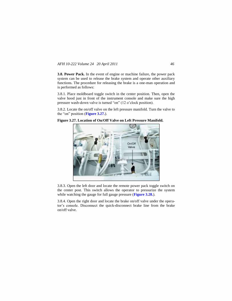
3.8. Power Pack. In the event of engine or machine failure, the power pack
system can be used to release the brake system and operate other auxiliary
functions. The procedure for releasing the brake is a one-man operation and
is performed as follows:
3.8.1. Place moldboard toggle switch in the center position. Then, open the
valve hood just in front of the instrument console and make sure the high
pressure wash-down valve is turned ―on‖ (12 o’clock position).
3.8.2. Locate the on/off valve on the left pressure manifold. Turn the valve to
the ―on‖ position (Figure 3.27.).
Figure 3.27. Location of On/Off Valve on Left Pressure Manifold.
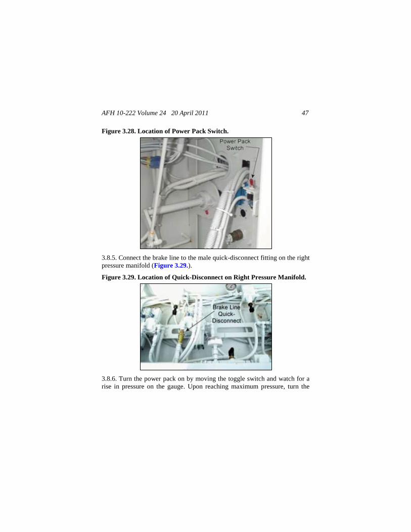
3.8.3. Open the left door and locate the remote power pack toggle switch on
the center post. This switch allows the operator to pressurize the system
while watching the gauge for full gauge pressure (Figure 3.28.).
3.8.4. Open the right door and locate the brake on/off valve under the opera-
tor’s console. Disconnect the quick-disconnect brake line from the brake
on/off valve.
AFH 10-222 Volume 24 20 April 2011 47
Figure 3.28. Location of Power Pack Switch.
3.8.5. Connect the brake line to the male quick-disconnect fitting on the right
pressure manifold (Figure 3.29.).
Figure 3.29. Location of Quick-Disconnect on Right Pressure Manifold.
3.8.6. Turn the power pack on by moving the toggle switch and watch for a
rise in pressure on the gauge. Upon reaching maximum pressure, turn the

AFH 10-222 Volume 24 20 April 2011 48
brake on/off valve (Figure 3.27.) to the ―off‖ position. The brakes will be
disengaged.
3.8.7. Continue holding the switch and the pressure will begin to rise on the
power pack pressure gauge. While holding the power pack switch, operate
any function to lift the machine out of the cut or move the conveyors to any
position.
3.8.8. Make all necessary engine or machine repairs.
3.8.9. Disconnect the brake female quick-disconnect fitting from the power
pack male quick-disconnect fitting under the instrument panel.
3.8.10. Re-connect the brake female quick-disconnect fitting to the brake
male quick disconnect-fitting under the instrument panel.
3.9. High Pressure Wash-down. Removal of asphalt and concrete from the
machine is accomplished by utilizing the machine’s high pressure system. A
daily routine of machine wash-down should be completed at the end of each
milling day and prior to any greasing. A daily routine of machine wash-
down increases the reliability and safety of your machine in addition to pro-
viding pride in its appearance.
3.9.1. The high pressure wash-down hose can be accessed from the hose reel,
which is located on the left hand side of the front of the machine. The high
pressure wash-down wand is located in the toolbox. The high pressure wash-
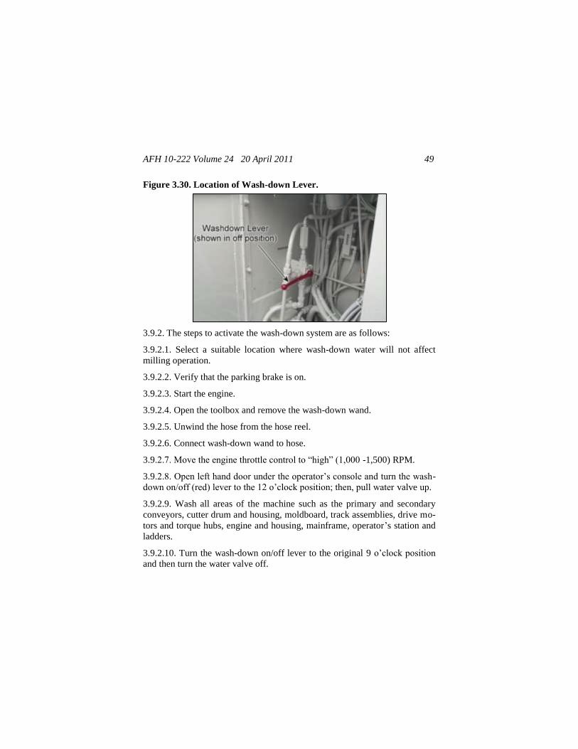
down system is activated from the wash-down lever located under the opera-
tor’s console (Figure 3.30.).
CAUTION!
Operate the power pack continuously for a maximum of one
minute. After every minute of continuous power pack operation, a
minimum of four minutes cooling must be allowed! The ignition
switch must be on!
AFH 10-222 Volume 24 20 April 2011 49
Figure 3.30. Location of Wash-down Lever.
3.9.2. The steps to activate the wash-down system are as follows:
3.9.2.1. Select a suitable location where wash-down water will not affect
milling operation.
3.9.2.2. Verify that the parking brake is on.
3.9.2.3. Start the engine.
3.9.2.4. Open the toolbox and remove the wash-down wand.
3.9.2.5. Unwind the hose from the hose reel.
3.9.2.6. Connect wash-down wand to hose.
3.9.2.7. Move the engine throttle control to ―high‖ (1,000 -1,500) RPM.
3.9.2.8. Open left hand door under the operator’s console and turn the wash-
down on/off (red) lever to the 12 o’clock position; then, pull water valve up.
3.9.2.9. Wash all areas of the machine such as the primary and secondary
conveyors, cutter drum and housing, moldboard, track assemblies, drive mo-
tors and torque hubs, engine and housing, mainframe, operator’s station and
ladders.
3.9.2.10. Turn the wash-down on/off lever to the original 9 o’clock position
and then turn the water valve off.

AFH 10-222 Volume 24 20 April 2011 50
3.9.2.11. Return the engine throttle control to the ―low‖ RPM.
3.9.2.12. Remove the wash-down wand from the wash-down hose.
3.9.2.13. Return the wand to the toolbox and the hose to the hose reel.
3.9.2.14. Shut down engine.
3.10. Grad-Line Slope Control System. The control module and handset
are mounted and removed each working day and stored in the grad-line car-
rying case in order to prevent damaging moisture exposure and to protect
against vandalism. When setting up the grad-line system for daily operation,
mount the control module to the mounting frame assembly on top of the mil-
ling machine by the instrument panel. Daily calibration of the grad-line slope
control system is required by the machine operator in order to set the ma-
chine up for slope control. These settings determine how precise and accu-
rate the grad-line system stays on slope during milling operation. The fea-
tures, which must be entered in order for the control box to function proper-
ly, are: zeroing or nulling of the control module and sensitivity. Refer to
Figure 2.2. for an illustration of the grad-line control module and handset.
3.10.1. Grad-line Installation and Calibration.
3.10.1.1. Level machine transversely and longitudinally by raising or lower-
ing the leg tube cylinders.
3.10.1.2. Place the control module onto the mounting plate on the milling
machine and latch the locking clips onto the side of the control module.
3.10.1.3. Connect the control module electrical cable to the slope/grade am-
phenol connector on the left side milling machine instrument panel.
NOTE!
In order for the grad-line slope control system to be calibrated prop-
erly the hydraulic system must be at normal operating temperature;
therefore run the machine hydraulic system for five minutes before
attempting to set the TOPCON system.
AFH 10-222 Volume 24 20 April 2011 51
3.10.1.4. Turn the grade/slope toggle switch to the ―on‖ position on the left
side milling machine instrument panel.
3.10.1.5. Turn the control module slope switch to the left direction (the side
of the machine that slope is controlled by).
3.10.1.6. Switch the control module to the standby setting.
3.10.1.7. Adjust the handset % slope to 00.0% by turning the thumbwheel on
the side of the handset. Turn the thumbwheel until both up and down arrow
lights are out.
3.10.1.8. Push and hold the reset button on the side of the handset. Turn the
thumbwheel until the % slope indicator reads 00.0%. Release the reset but-
ton.
3.10.1.9. The control module is now calibrated; both lights on the arrow up
and down should be off. If a light is still on or blinking, repeat steps in para-
graphs 3.10.1.3. thru 3.10.1.8. above.
3.10.1.10. With the power to the control module ―on,‖ turn the sensitivity
knob to 6.
3.10.1.11. Turn the control module standby switch to ―on.‖
3.10.1.12. Turn the sensitivity switch clockwise until the milling machine
left side leg tube begins to oscillate.
3.10.1.13. Turn the sensitivity switch counterclockwise until the milling ma-
chine left side leg tube becomes stable again.
3.10.1.14. Turn off the grade/slope switch on the milling machine instrument
panel.
3.10.1.15. Disconnect the control module electrical cable from the left side
slope/grade amphenol connector and connect to the right side slope/grade
amphenol connector on the milling machine instrument panel.
3.10.1.16. Turn the grade/slope toggle switch to the ―on‖ position on the
right side milling machine instrument panel.
3.10.1.17. Turn the control module slope switch to the right side direction.
AFH 10-222 Volume 24 20 April 2011 52
3.10.1.18. Switch the control module to the standby setting.
3.10.1.19. Adjust the handset % slope to 00.0% by turning the thumbwheel
on the side of the handset.
3.10.1.20. Turn the thumbwheel on the handset until the milling machine
right side leg tube stops elevating. The arrow up light on the control module
should be off.
3.10.1.21. Push and hold the reset button on the side of the handset. Turn the
thumbwheel until the % slope indicator reads 00.0%. Release the reset but-
ton.
3.10.1.22. The control module is now calibrated; both lights on the arrow up
and down should be off. If a light is still on or blinking, then repeat steps in
paragraphs 3.10.1.15. thru 3.10.1.21.
3.10.1.23. With the power to the control module ―on,‖ turn the sensitivity
knob to 6.
3.10.1.24. Turn the control module standby switch to ―on.‖
3.10.1.25. Turn the sensitivity switch clockwise until the milling machine
right side leg tube begins to oscillate.
3.10.1.26. Turn the sensitivity switch counterclockwise until the milling ma-
chine right side leg tube becomes stable again.
3.10.1.27. Turn off the grade/slope switch on the milling machine instrument
panel.
3.11. TOPCON Grade/Slope Systems.
13.11.1. Operating Setting. The control boxes and sonic trackers are
mounted and removed each working day and stored in the TOPCON carry-
ing case in order to prevent damaging moisture exposure and to protect
against vandalism. The slope sensor, jog switches and junction boxes are
mounted on the machine and are not removed once installed. When setting
up the TOPCON system for daily operation, mount the sonic trackers to the
mounting frame assembly at the side of the machine and the control boxes to
the top left and right side of the machine. Mount the control box with the ―L‖
AFH 10-222 Volume 24 20 April 2011 53
marked on the side of the control box to the left side of the machine and
mount the control box with the ―R‖ marked on the side of the control box on
the right side of the machine. Reversing the left and right control boxes with
the left and right side of the machine will cause the TOPCON system to
function improperly. After the hardware and electrical cables are connected,
proceed to the operator setting section below.
3.11.1.1. The operator settings are a series of features, which must be entered
into the TOPCON control box by the machine operator in order to set the
machine up for grade and slope control by the TOPCON system. These set-
tings determine how precise and accurate the TOPCON system stays on
grade and slope during milling operation. The setting features, which must
be entered in order for the control box to function properly, are: gain (eleva-
tion, gain (slope), slope resolution, beeper, hour meter, deadband, valve off-
sets and units. Refer to Figure 2.4. for an illustration of the TOPCON
Grade/Slope Control Box.
3.11.1.2. Level machine transversely and longitudinally by raising or lower-
ing the leg tube cylinders.
3.11.1.3. Turn on the TOPCON Grade and Slope Control Box and access the
operator’s settings by holding the auto/manual/survey (cal.) switch down
while holding the elevation/slope switch either up or down.
3.11.1.4. Continue holding the auto/manual/survey (cal.) and elevation/slope
switches while the TOPCON revision number and machine code are flashed
across the liquid crystal display (LCD) (in the event that an uncorrectable
error may occur, the TOPCON revision number and machine code will have
to be copied so that you can identify the specific TOPCON program on your
system when discussing the problem with TOPCON personnel).
NOTE!
In order for the TOPCON Grade and Slope Control System to be
calibrated properly the hydraulic system must be at normal operating
temperature. Therefore, run the machine hydraulic system for at least
five minutes before attempting to set the TOPCON System.
AFH 10-222 Volume 24 20 April 2011 54
3.11.1.5. Release the elevation/slope switch but continue holding the au-
to/manual/survey (cal.) switch down on the control box and wait until the red
arrows on the grade adjustment knob flash and the blank screen appears on
the display of the control box.
3.11.1.6. Continue to hold the auto/manual/survey (cal.) switch down and
turn the grade adjustment knob until the gain (elevation) symbol appears as
―gAn‖ on the LCD display. Release the auto/manual/survey (cal.) switch and
turn the grade adjustment knob until 25 appears on the display of the control
box. Hold down on the auto/manual/survey (cal.) switch for about two to
three seconds.
3.11.1.7. Depress the auto/manual/survey (cal.) switch down and turn the
grade adjustment knob until the gain (slope) symbol appears as ―gAn‖ on the
LCD display. Release the auto/manual/survey (cal.) switch and turn the
grade adjustment knob until 25 appears on the display of the control box.
Hold down on the auto/manual/survey (cal.) switch for about two or three
seconds.
3.11.1.8. Depress the auto/manual/survey (cal.) switch down and turn the
grade adjustment knob until the slope resolution symbol appears as ―SLP‖
on the LCD display. Release the auto/manual/survey (cal.) switch and turn
the grade adjustment knob until ―.1‖ appears on the display of the control
box. Hold down on the auto/manual/survey (cal.) switch for about two to
three seconds.
3.11.1.9. Depress the auto/manual/survey (cal.) switch down and turn the
grade adjustment knob until the beeper symbol appears and ―bEP‖ on the
LCD display. Release the auto/manual/survey (cal.) switch and turn the
grade adjustment knob until ―OFF‖ appears on the display of the control
box. Hold down on the auto/manual/survey (cal.) switch for about two to
three seconds.
3.11.1.10. Depress the auto/manual/survey (cal.) switch down and turn the
grade adjustment knob until the hour meter symbol appears as ―Hr‖ on the
LCD display. Release the auto/manual/survey (cal.) switch and turn the
grade adjustment knob until the hour meter reading appears on the display of
the control box. If the TOPCON grade and slope control box has not been
AFH 10-222 Volume 24 20 April 2011 55
used, a blank screen will appear instead of a numerical value. Hold down on
the auto/manual/survey (cal.) switch for about two to three seconds.
3.11.1.11. Depress the auto/manual/survey (cal.) switch down and turn the
grade adjustment knob until the deadband symbol appears as ―dB‖ on the
LCD display. Release the auto/manual/survey (cal.) switch and turn the
grade adjustment knob until ―03‖ appears on the display of the control box.
Hold down the auto/manual/survey (cal.) switch for about two or three
seconds.
3.11.1.12. Depress the auto/manual/survey (cal.) switch down and turn the
grade adjustment knob until the valve offset symbol appears as ―OFS‖ on the
LCD display. Position an extra man on the ground standing at the front leg
tubes with his index finger placed on the machine waiting to detect upward
movement in the leg tubes. Continue to hold the auto/manual/survey (cal.)
switch down and turn the grade adjustment knob in the direction so that the
numeric numbers on the display of the control box are increasing (the valve
offset for proportional valves is around 240 or above). When the ground man
senses that the machine is beginning to raise, stop turning the grade adjust-
ment knob and release the auto/manual/survey (cal.) switch. The leg tube
cylinder proportional valve offset is set for the upward movement and must
be set for the downward movement.
3.11.1.13. Depress the auto/manual/survey (cal.) switch down and turn the
grade adjustment knob in the direction so that the numeric numbers on the
display of the control box are increasing (the valve offset for proportional
valves is around 240 or above). When the ground man senses that the ma-
chine is beginning to lower, stop turning the grade adjustment knob and re-
lease the auto/manual/survey (cal.) switch. The leg tube cylinder proportion-
al valve offset is set for the downward movement.
3.11.1.14. Depress the auto/manual/survey (cal.) switch down and turn the
grade adjustment knob until the unit symbol appears as ―unt‖ on the LCD
display. Release the auto/manual/survey (cal.) switch and turn the grade ad-
justment knob until ―in‖ appears on the display of the control box. Hold
down on the auto/manual/survey (cal.) switch for about two to three seconds.
AFH 10-222 Volume 24 20 April 2011 56
3.11.1.15. Depress the auto/manual/survey (cal.) switch down and turn the
grade adjustment knob until the blank screen appears on the LCD display.
Release the auto/manual/survey (cal.) switch. The Operator’s performance
settings are stored in the TOPCON grade/slope control box’s memory and
will be saved when the power is turned off to the unit. During performance
setting sequence the blank screen must be accessed before exiting from the
operator setting sequence or the settings will not be saved in the control
box’s memory.
3.12. Maintenance Safety Precautions. Adhere to the following safety pre-
cautions when performing maintenance on the milling machine. See the
manufacturer’s Operation and Service Manual for actual maintenance re-
quirements and instructions.
3.12.1. Never service, clean, or examine the unit with the engine running.
3.12.2. Never service or perform maintenance to the unit unless the track
safety bars are in place.
3.12.3. Never fill the tank with the engine running, while near an open flame,
or when smoking. Always wipe up spilled fuel.
3.12.4. Never remove the pressurized radiator cap until the engine’s cooling
system has cooled.
3.12.5. Do not alter the engine governor settings from that indicated in the
engine manual and engine option plate.
WARNING!
Before doing any maintenance, service, or repairs, read and under-
stand the safety precautions identified in paragraph 2.5. of this pub-
lications to avoid personal injury.
WARNING!
Do not work under this machine with the engine running or without
the safety bars in place. This could result in serious injury or death.
AFH 10-222 Volume 24 20 April 2011 57
3.12.6. Never change cutter drum teeth while the engine is running.
3.12.7. Always replace damaged or lost decals. Refer to the parts manual for
the proper location and part number of all decals.
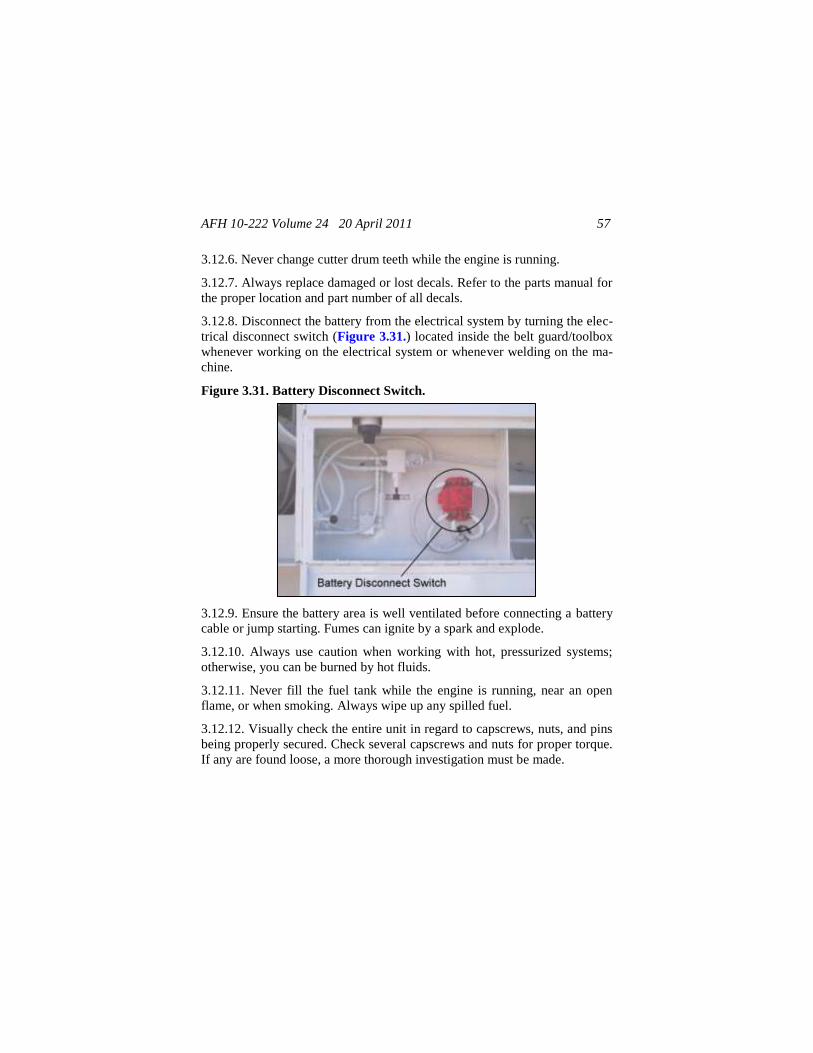
3.12.8. Disconnect the battery from the electrical system by turning the elec-
trical disconnect switch (Figure 3.31.) located inside the belt guard/toolbox
whenever working on the electrical system or whenever welding on the ma-
chine.
Figure 3.31. Battery Disconnect Switch.
3.12.9. Ensure the battery area is well ventilated before connecting a battery
cable or jump starting. Fumes can ignite by a spark and explode.
3.12.10. Always use caution when working with hot, pressurized systems;
otherwise, you can be burned by hot fluids.
3.12.11. Never fill the fuel tank while the engine is running, near an open
flame, or when smoking. Always wipe up any spilled fuel.
3.12.12. Visually check the entire unit in regard to capscrews, nuts, and pins
being properly secured. Check several capscrews and nuts for proper torque.
If any are found loose, a more thorough investigation must be made.
AFH 10-222 Volume 24 20 April 2011 58
3.12.13. The operating temperature of the system should not exceed 180 de-
grees Fahrenheit (82 degrees Celsius) continuous and 220 degrees Fahren-
heit (104 degrees Celsius) intermittent at the case drain.
3.12.14. Under operating conditions, the fluid viscosity must be above 55
SUS (9cST) continuously and never less than 47 SUS (6.4 cST).
3.13. Lubrication. It cannot be overstated that the life and reliability of a
milling machine is greatly affected by the type, frequency, and care of lubri-
cation. Dirt particles that are difficult to see with the human eye can cause
many thousands of dollars worth of damage to a mechanical or hydraulic
system. Lubricants must be properly stored in clean and covered containers
that are properly marked to identify their use. If containers are used to carry
lubricants from bulk storage tanks, they should be thoroughly cleaned and
provided with covers. See the manufacturer’s Operation and Service Manual
for the lubrication requirements and instructions.
3.13.1. A lubrication schedule is provided in the manufacture’s Operation
and Service Manual with suggested service intervals. If operating conditions
are severe, shorter intervals may be required. Only quality lubricants should
be used which conform to the lubricant specifications. Fluid levels should be
checked when the machine is parked on a level surface.
3.13.2. Before removing caps and plugs, thoroughly clean the area around
them. Grease fittings and grease gun adapters must be cleaned before inject-
ing grease. Funnels should be washed with solvents and thoroughly dried
before and after use. Clean all grease fittings after use and wipe up spilled
oils to avoid accumulation and hazardous walkways.
3.13.3. Lubrication should be performed at the end of the day right after the
machine has been washed down. Lubricants and debris are most easily
flushed while they are warm. This is particularly true in the material han-
dling areas of the machine.
3.13.4. Over lubrication on non-sealed fittings will not harm the fittings or
components, but under lubrication will definitely lead to a shorter life.
3.13.5. All grease fittings are Society of Automotive Engineers (SAE) stan-
dard unless otherwise noted. Grease unsealed fittings until grease is seen
AFH 10-222 Volume 24 20 April 2011 59
extruding from the fitting. One ounce of EP-MPG equals one pump on a
standard grease gun.
3.13.6. Clean fuel, lubricants, and hydraulic oil from walkways or loss of
footing may occur resulting in serious injury or even death.
3.13.7. Unless otherwise indicated, items not equipped with grease fittings,
such as linkages, pins levers, should be lubricated with oil once a week. Mo-
tor oil, applied sparingly, will provide the necessary lubrication and help
prevent the formation of rust. An anti-seize compound may be used if rust
has not formed, otherwise the part must be cleaned first.
3.13.8. Lubricants must be at operating temperature when draining.
3.14. Changing Cutting Teeth. The life of the cutter drum teeth will vary
with the type of material being cut, the temperature and the span of opera-
tion. The machine can mill approximately 2,000 feet in soft asphalt before
inspecting the teeth. Check the length of the teeth once an hour and replace
them before the carbide insert is worn completely. If the teeth are not re-
placed when needed, the holders will start hitting and be severely damaged
or even torn from the cutter drum. It is much easier to replace the teeth than
to replace a holder and teeth. Perform the following steps to inspect and
change cutting teeth.
WARNING!
Shut engine off and lock pins in place before replacing teeth.
WARNING!
Always use eye protection whenever replacing cutter drum teeth.
CAUTION!
Do not lower the cutting drum when the cutter is not turning. The
weight of the cutter drum can break the teeth and can damage the
cutter drum and/or bearings.
AFH 10-222 Volume 24 20 April 2011 60
3.14.1. At low idle only, disengage the clutch.
3.14.2. Take the rear moldboard out of the float position and then raise it to
expose the teeth. To raise it higher, pull out on safety lock at the top-left of
the mold board. With opposite hand reach directly behind you to move the
red toggle switch to raise the moldboard higher. This will enact an engine
safety that will cause the engine to shut down. It will not start again until the
moldboard is lowered with the red toggle switch (pull the safety pin out
while lowering).
3.14.3. An air hammer, a straight punch for the air hammer and a drive pin
can be used to replace the teeth quickly. To change a tooth without the use of
an air hammer, insert the tip of the drive pin into the opening in the rear of
the tooth holder and strike the drive pin sharply with a hammer to dislodge
the tooth.
3.14.4. If a tooth holder is found to be broken, stick the long bent tool in the
back of it and pound it out. Line up the groove to pound a new one in.
3.14.5. Insert a new tooth into the holder with a hammer so that the keeper
spring is engaged with the holder.
AFH 10-222 Volume 24 20 April 2011 61
Chapter 4
GENERAL MILLING PRACTICES
4.1. Milling Preparation.
4.1.1. Obtain project drawings from the customer and ensure they show 1)
location and extent of pavement; 2) required elevation of finish surface of
new pavement; 3) a section indicating in mm (inches) the depth that the ex-
isting pavement has to be removed; 4) the location of existing manholes,
valve boxes, in-pavement lights, and utility lines; and 5) location of pave-
ment reinforcement layers (e.g., fabrics and/or grids) if applicable.
4.1.2. Provide notice to civil engineer unit at least seven days prior to start-
ing work to allow them to coordinate the milling operation with other base
agencies at the site.
4.1.3. If the milled material is to be recycled, clean the pavement surface of
excessive dirt, clay, or other foreign material immediately prior to milling
the pavement.
4.2. Milling Operation. Provide all necessary traffic controls during milling
operations. Milling shall not be performed when there is accumulation of
snow or ice on the pavement surface.
4.2.1. Make sufficient passes so that the designated area is milled to grades
and cross sections indicated. Proceed with care and in depth increments that
will not damage the pavement below the designated finished grade.
4.2.2. If design does not include removal of base course material and it is
desired not to disturb the base course, ensure only bituminous pavement is
removed and base course is not disturbed. Leave in place a layer of bitumin-
ous pavement, .25 to .5 inch thick, over the undisturbed base course. Fur-
thermore, when a paving fabric or grid is known to exist in the underlying
pavement structure and is to remain in place, mill no closer to the fabric or
grid than a distance equal to the top size of the in place aggregate (typically
.5 to .75 inches).
AFH 10-222 Volume 24 20 April 2011 62
4.2.3. When the milled material is to be cold recycled, the maximum size for
the cuttings should be equal to or less than one-half of the recycled pavement
thickness. Generally, the maximum size for a single 4 inch lift of pavement
will be 2 inches or less. Removed material shall meet the design require-
ments and be in accordance with American Society for Testing and Materials
(ASTM) C 136.
4.2.4. Remove and distribute/dispose of the milled material as specified in
the project plans. Store or stockpile materials milled from different pavement
sections in separate homogeneous stockpiles rather than conglomerate stock-
piles. Homogeneous RAP sources are more consistent in terms of asphalt
binder and aggregate type and properties, and will lead to improved consis-
tency in mixture design and a better finished product. Milled materials
should be fractionated (i.e., separated/sieved) when used in RAP to ensure
proper mix design and production control.
4.2.5. When the milling is done under traffic maintained conditions:
4.2.5.1. Uniformly mill the entire lane width with one machine or a combina-
tion of milling machines in tandem.
4.2.5.2. Milling should be performed on the adjacent lane in the same day if
the milling results in a vertical longitudinal face greater than 1 inch in depth
between the lanes. At the end of each day, no more than 500 feet should
have a drop off of over 1 inch. Work should be scheduled so that a vertical
drop off will not be present between traffic lanes over weekends, holidays, or
other extended periods when work is not being performed.
4.2.5.3. Transitions between milled and unmilled surfaces should be fea-
thered either by milling or with wedges of bituminous material (maximum
slope: 1 horizontal to 4 vertical).
4.2.5.4. When working to adjacent traffic, if the milled material spills in the
traveled way, immediately remove the material.
4.2.6. Surfacing material that cannot be removed by milling equipment be-
cause of physical or geometric constraints should be removed by other me-
thods approved by the project engineer.
AFH 10-222 Volume 24 20 April 2011 63
4.2.7. If traffic has been detoured from the milled area, the surface should be
swept once per day. When milling is performed under traffic maintained
conditions, the milled surface should be swept before opened to traffic.
4.2.8. When both the driving lane(s) and shoulders are to be milled, they
should be milled the same day to eliminate traffic lane surface drainage re-
strictions.
4.2.8.1. When the surfaced shoulders are not milled, drainage channels in the
shoulders may be cut by milling or by any other method approved by the
project engineer. The width should be 2 feet minimum, and the depth should
be the same as the milling depth with sufficient spacing to provide proper
drainage. This operation should be performed as directed by the project en-
gineer.
4.2.8.2. Drainage channels should be repaired by patching with asphaltic
concrete of the type in the adjacent surfacing before the outside surfaced
shoulder are fog sealed or surfaced.
4.2.8.3. Earth shoulders should be cut to an elevation that will allow drai-
nage.
4.2.9. Damage to milled surfaces, prior to overlaying, resulting from traffic
or other causes such as, but not limited to , raveling, fuel spillage or any con-
taminates which would inhibit bonding shall be repaired or remilled in a
manner approved by the project engineer.
4.3. Quality Control Requirements.
4.3.1. Grade-Conformance Tests. Test the finished milled surface of the
pavement for conformance with the plan-grade requirements and for accep-
tance by the approving Officer by running lines of levels at customer speci-
fied intervals (typically 25 feet longitudinally and 25 feet transversely) to
determine the elevation of the completed pavement. The finished milled
pavement surfaces should not vary more than .25 inch from the established
plan grade line and elevation. Correct variations from the designated grade
line and elevation in excess of the plan-grade requirements as directed. Typi-
cally, skin patching for correcting low areas will not be permitted; remove
AFH 10-222 Volume 24 20 April 2011 64
and replace the deficient low area. Remove sufficient material to allow at
least 1 inch of asphalt concrete to be placed.
4.3.2. Surface-Smoothness Tests. After completion of the final milling, the
finished milled surface is typically tested with a straightedge. Other ap-
proved devices may be used, provided that when satisfactorily and properly
operated, such devices reveal all surface irregularities exceeding the toler-
ances specified. Correct surface irregularities that depart from the testing
edge by more than 0.25 inch. Typically, skin patching for correcting low
areas will not be permitted; remove and replace the deficient low area. Re-
move sufficient material to allow at least 1 inch of asphalt concrete to be
placed.
4.4. Post Operation.
4.4.1. Repair or replace, as directed, items damaged during milling such as
manholes, valve boxes, utility lines, pavement that is torn, cracked, gouged,
broken, or undercut.
4.4.2. After milling, pavement surfaces should be cleaned off by sweeping or
washing before any overlay is placed; otherwise, debris such as dirt and dust
may decrease bonding between the new overlay and the existing pavement.
When sweeping, more than one pass is typically needed to remove all the
debris; continue sweeping until all debris is removed. If the milled surface is
washed, the pavement must be allowed to dry prior to paving.
4.4.3. When the milled surface is to be opened to traffic:
4.4.3.1. Vertical cuts resulting in an elevation differential of greater than 2
inches along a gutter line or shoulder line should be protected by temporary
barricades and warning signs erected.
NOTE!
For pavements in aircraft traffic areas such as airfield runways and
taxiways, lines of levels to determine elevation of the milled pave-
ment will be run longitudinally and transversely at intervals not ex-
ceeding 25 feet.
AFH 10-222 Volume 24 20 April 2011 65
4.4.3.2. If milling removed pavement markings, temporary pavement mark-
ing should be placed before opening the road for public use.
4.4.3.3. If opened to traffic longer than 30 days, the texture produced by the
milling operation should be uniform and provide a satisfactory riding surface
and skid resistance. Continuous longitudinal striations should not be al-
lowed.
HERBERT J. CARLISLE, Lt General, USAF
DCS/Operations, Plans, and Requirements (A3/5)
AFH 10-222 Volume 24 20 April 2011 66
Attachment 1
GLOSSARY OF REFERENCES
AND
SUPPORTING INFORMATION
References
AFDD 4-0, Combat Support, 23 March 2005
AFPD 10-2, Readiness, 30 October 2006
AFI 10-209, RED HORSE Program, 13 May 2008
Operation, Service & Maintenance for the RX-60C Milling Machine, P.N.
200501 ©ROADTEC, INC. September 2000
UFC 3-250-03, Standard Practice Manual for Flexible Pavements, 15 May
2001
UFC 3-250-07, Standard Practice for Pavement Recycling, 16 January 2004
UFGS-32 01 16.17, Cold Milling of Bituminous Pavements, August 2008
Prescribed Forms
None
Abbreviations and Acronyms
AFI—Air Force Instruction
AFMAN—Air Force Manual
AFRIMS—Air Force Records Information Management System
ANG—Air National Guard
AFRC—Air Force Reserve Command
ASTM—American Society for Testing and Materials
ATTLA—Air Transportability Test Loading Activity
AFH 10-222 Volume 24 20 April 2011 67
CPL—control parts list
ECM—electronic control module
ESN—engine serial number
FOD—foreign object damage
HMA—hot mix asphalt
hp—horse power
LCD—liquid crystal display
MAJCOM—Major Command
PCC—Portland cement concrete
PSI—pounds per square inch
PTO—power take-off
RAP—reclaimed asphalt pavement
RDS—Records Disposition Schedule
RPM—rotations per minute
SAE—Society of Automotive Engineers
Terms
aggregate—any of various loose, particulate materials, as sand, gravel, or
pebbles, added to a cementing agent to make concrete, plaster, etc.
asphalt—a mixture of substances such as bitumen with gravel, crushed rock,
or the like, used for paving.
asphalt emulsion—a mixture of asphalt and petroleum solvents to form
―cutbacks‖ with reduced melting point or mixtures with water allowing as-
phalt to be mixed at much lower temperatures.
base course—the sub-layer material of asphalt concrete pavements or Port-
land cement concrete pavements that is placed directly on top of the undis-
AFH 10-222 Volume 24 20 April 2011 68
turbed soil so as to provide a foundation to support the top layer(s) of the
pavement.
binder material—an ingredient used to bind together two or more materials
in mixtures. Its two principle properties are adhesion and cohesion.
bitumen—mixture of organic liquids that are highly viscous, black, sticky,
entirely soluble in carbon disulfide, and composed primarily of highly con-
densed polycyclic aromatic hydrocarbons; primarily used for paving roads.
filler material—fills the voids between aggregate grains and improves the
wearing capabilities of the overall mix
gradation—the proportion of particles (such as aggregate) of a given size
within a sample of particulate material, such as soil or sandstone; the aggre-
gates particle size distribution.
heater-Planing—heating the surface of a bituminous concrete pavement and
planing the surface to the desired grade.
hydroplaning—occurs when a layer of water builds between the rubber tires
of the vehicle and the road surface, leading to the loss of traction and thus
preventing the vehicle from responding to control inputs such as steering,
braking or accelerating.
leveling course—initial lifts placed directly on to the existing pavement to
fill low spots in the pavement.
milling (also called grinding or cold planning)—removing a layer of pave-
ment by a milling machine; used to smooth an existing pavement prior to
flexible or rigid overlays; allows curb and gutter lines to be maintained or
reestablished before flexible overlays; provides an efficient removal tech-
nique for material near overhead structures in order to maintain clearances
for bridge structures, traffic signals, and overhead utilities.
nuclear gauge density testing—a test procedure for determining the density
of bituminous concrete by the attenuation of gamma radiation where the
source and detector remain on the surface.
AFH 10-222 Volume 24 20 April 2011 69
pavement recycling—a process that recycles the existing asphalt in-place,
with the addition of some new aggregates and emulsion, to provide a new
pavement material layer.
Portland cement concrete (PCC)—used to produce rigid pavements con-
sisting of a PCC slab that is usually supported by a granular or stabilized
base, and a sub-base. In some cases the PCC slab may be overlaid with a
layer of asphalt concrete.
raveling—a form of pavement distress involving the dislodgement of aggre-
gates from the surface of an asphalt pavement.
recycled cold mix—mixing RAP as an aggregate with new emulsified or
foamed asphalt and/or a recycling or rejuvenating agent, possibly also with
virgin aggragate, without the use of heat.
recycled hot mix—mixing heated RAP with a recycling or rejuvenating
agent, possibly adding virgin asphalt and/or aggregate, and replacing it on
the pavement
rejuvenator—reconditions asphalt pavements by penetrating somewhat into
the asphalt concrete and soften (rejuvenate) the asphalt binder. The rejuvena-
tor also helps to seal the pavement and minimize future oxidation.
tack coat—diluted emulsified asphalt materials placed on an existing pave-
ment surface prior to a hot-mix asphalt overlay. It provides the necessary
bond between the underlying/adjacent layers and the new pavement surface.