Embed Size (px)
Citation preview
Administrative Changes to AFH 10-222, Volume 10, Civil Engineer Camouflage, Concealment,
and Deception Measures
OPR: AFCEC/CXX
References throughout to “HQ AFCESA/CEXX” are hereby changed to “AFCEC/CXX.”
Delete reference throughout to “AFI 10-211, Civil Engineer Contingency Response Planning.”
References throughout to “AFI 10-2501, Air Force Emergency Management (EM) Program
Planning and Operation,” are hereby changed to “AFI 10-2501, Air Force Emergency
Management Program.”
References throughout to “Air Force Doctrine Document (AFDD)” are hereby changed to “Air
Force Doctrine Annex (AFDA).”
References throughout to “AFDD 2-4, Agile Combat Support,” are hereby changed to “AFDA 4-
0, Combat Support.”
References throughout to “AFDD 2-34” are hereby changed to “AFDA 3-34.”
References throughout to “AFMAN 32-4005, Personnel Protection and Attack Actions,” are
hereby changed to “AFMAN 10-2503, Operations in a Chemical, Biological, Radiological,
Nuclear, and High-Yield Explosive (CBRNE) Environment.”
References throughout to “Comprehensive Emergency Management Plan (CEMP) 10-2” are
hereby changed to “Installation Emergency Management Plan (IEMP) 10-2.”
3 June 2016
AIR FORCE HANDBOOK 10-222, VOLUME 10
18 February 2011
BY ORDER OF THE AIR FORCE HANDBOOK10-222 SECRETARY OF THE AIR FORCE VOLUME 10
18 FEBRUARY 2011
Operations
CIVIL ENGINEER CAMOUFLAGE, CONCEALMENT, AND DECEPTION MEASURES
ACCESSIBILITY: Publications and forms are available on the e-Publishing
website at www.e-publishing.af.mil for downloading or ordering.
RELEASABILITY: No releasability restrictions on this publication.
OPR: HQ AFCESA/CEXX Certified by: HQ USAF/A7CX
(Col Jeffery A. Vinger)
Pages: 112
This handbook supports Air Force Instruction (AFI) 10-210, Prime Base
Engineer Emergency Force (BEEF) Program and AFI 10-211, Civil Engi-
neer Contingency Response Planning by describing civil engineers camouf-
lage, concealment, and deception (CCD) responsibilities in contingency op-
erations. This handbook includes responsibilities found in other references,
but otherwise is not directive or mandatory. Instead, it presents ideas and
concepts to consider throughout the planning and execution phases of the
civil engineer CCD plan. This handbook applies to deployed Air Force civil
engineer personnel, including Air National Guard (ANG) units and Air
Force Reserve Command (AFRC), civilian and contractor personnel who
may be tasked to execute a civil engineer CCD plan. Refer recommended
changes and questions about this publication to the office of primary respon-
sibility (OPR) using AF IMT 847, Recommendation for Change of Publica-
tion; route AF IMT 847s from the field through Major Command (MAJ-
COM) publications/forms managers. Ensure that all records created as a re-
sult of processes prescribed in this publication are maintained in accordance
with Air Force Manual (AFMAN) 33-363, Management of Records, and
disposed of in accordance with the Air Force Records Disposition Schedule
Certified Current 6 April 2015
AFH 10-222 Volume 10 18 February 2011 2
(RDS) located at https://www.my.af.mil/afrims/afrims/afrims/rims.cfm. The
use of the name or mark of any specific manufacturer, commercial product,
commodity, or service in this publication does not imply endorsement by the
Air Force.
Page
Chapter 1—INTRODUCTION ................................................................... 6
1.1. Overview ................................................................................... 6
Figure 1.1. Use of Artificial CCD Materials to Blend with Environment ...... 6
Figure 1.2. ADR Equipment Must Survive Enemy Attack ............................. 7
Figure 1.3. Airmen Placing Camouflage Netting over Fighting Position ...... 8
1.2. Responsibilities ......................................................................... 9
1.3. Doctrinal Considerations ......................................................... 11
Figure 1.4. Air Force Civil Engineer Publications Hierarchy. ...................... 12
Figure 1.5. Smoke Degrades Enemy Detection Systems ............................. 13
1.4. Priorities .................................................................................. 14
1.5. Training ................................................................................... 15
Figure 1.6. Airmen Conducting CCD Training ............................................ 15
1.6. Other Considerations ............................................................... 17
Chapter 2—THREAT ................................................................................ 18
2.1. Overview ................................................................................. 18
2.2. Data Collection ........................................................................ 18
2.3. Sensor Systems ........................................................................ 18
Figure 2.1. Night-Vision Device in Use ....................................................... 19
Figure 2.2. Binoculars Used for Surveillance .............................................. 19
2.4. CCD versus Threat Sensors ..................................................... 22
Chapter 3—FUNDAMENTALS ............................................................... 24
3.1. Overview ................................................................................. 24
3.2. Avoiding Detection ................................................................. 24
3.3. Identifying the Threat .............................................................. 24
AFH 10-222 Volume 10 18 February 2011 3
3.4. Avoiding Detection by Routine Surveillance .......................... 25
Figure 3.1. Darkness May Not Protect You from Surveillance .................... 25
3.5. Taking Countermeasures ......................................................... 25
3.6. Employing Realistic CCD ....................................................... 26
Figure 3.2. Correct Use of LCSS Can Help Defeat Visual Sensors ............. 26
3.7. Minimizing Movement ............................................................ 28
3.8. Using Decoys .......................................................................... 28
3.9. Applying Recognition Factors ................................................. 29
Figure 3.3. Match Paint Pattern to the Background ..................................... 32
3.10. Site Selection ........................................................................... 32
3.11. CCD Discipline ....................................................................... 33
3.12. Techniques .............................................................................. 35
Table 3.1. CCD Techniques ..................................................................... 35
Figure 3.4. Placing Netting over Vehicle to Blend with Background ........... 37
3.13. Natural Conditions .................................................................. 37
Figure 3.5. F-16 and Fuel Truck Decoys…Which F-16 is real? .................. 38
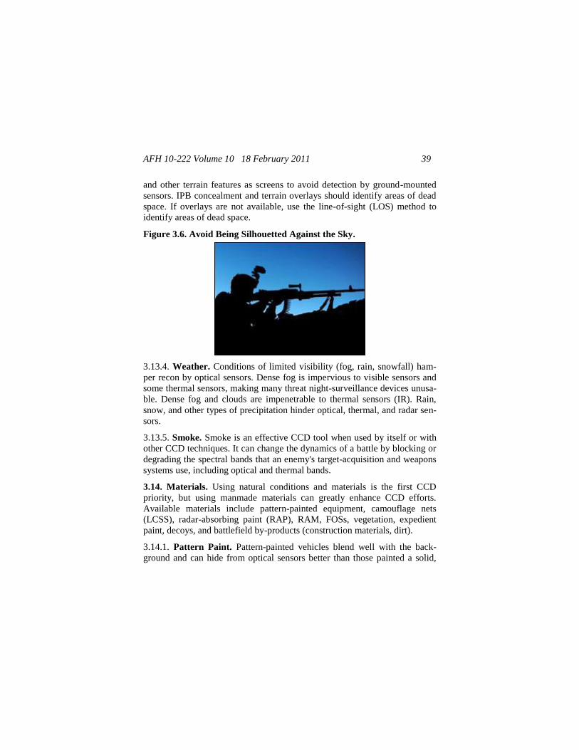
Figure 3.6. Avoid Being Silhouetted Against the Sky ................................. 39
3.14. Materials .................................................................................. 39
Figure 3.7. HMMWV with Pattern Paint Applied ....................................... 40
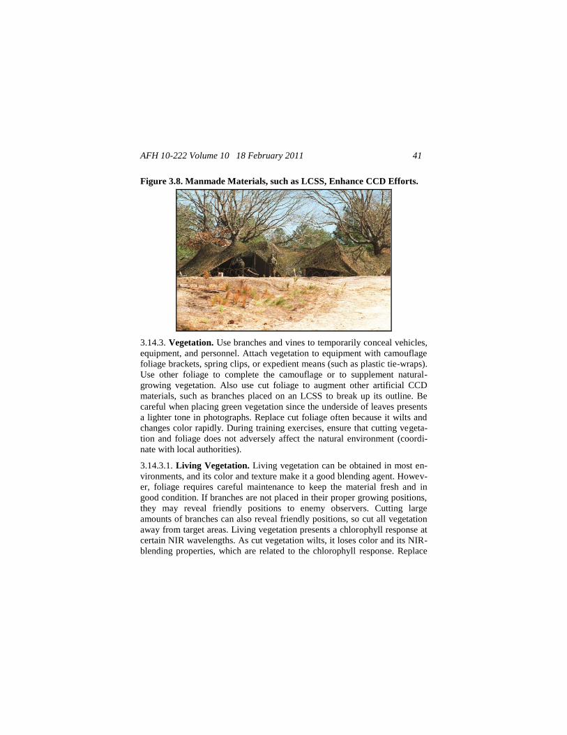
Figure 3.8. Manmade Materials, such as LCSS, Enhance CCD Efforts ....... 41
Table 3.2. Expedient Paints ...................................................................... 43
Chapter 4—DEFENSIVE OPERATIONS ............................................... 45
4.1. Overview ................................................................................. 45
4.2. Preparations ............................................................................. 45
Figure 4.1. Survivability Positions Provide Signals to the Enemy ............... 45
Figure 4.2. Camouflage Nets can Conceal High-Valued Targets ................ 47
4.3. Survivability Positions and Obstacles ..................................... 48
4.4. Battle ....................................................................................... 49
AFH 10-222 Volume 10 18 February 2011 4
Chapter 5—HIGH VALUE TARGETS ................................................... 51
5.1. Overview ................................................................................. 51
5.2. Plans ........................................................................................ 51
5.3. Objective ................................................................................. 51
5.4. Planning Process ..................................................................... 52
5.5. Fixed Installations ................................................................... 53
Chapter 6—SPECIAL ENVIRONMENTS ............................................. 63
6.1. Overview ................................................................................. 63
6.2. Desert ...................................................................................... 63
6.3. Snow-Covered Areas ............................................................... 64
Figure 6.1. Arctic CCD ................................................................................ 65
6.4. Urban Terrain .......................................................................... 66
Chapter 7—INDIVIDUAL CCD .............................................................. 68
7.1. Overview ................................................................................. 68
7.2. Materials .................................................................................. 68
Figure 7.1. Airman Applying Skin Paint ...................................................... 68
7.3. Discipline ................................................................................ 68
7.4. Dispersal .................................................................................. 69
7.5. Considerations ......................................................................... 69
Figure 7.2. Burlap Covering Headlight ...................................................... 70
7.6. Employment ............................................................................ 70
Figure 7.3. Work in Pairs when Applying Skin Paint ................................ 71
Table 7.1. Application of Camouflage Face Paint to Skin ....................... 72
Figure 7.4. CCD Applied to Helmet .......................................................... 72
Figure 7.5. Camouflaged Fighting Position ................................................. 73
Figure 7.6. Camouflaged Dug-in Fighting Position ..................................... 75
Chapter 8—DISPERSAL PROCEDURES .............................................. 76
8.1. Introduction ............................................................................. 76
AFH 10-222 Volume 10 18 February 2011 5
8.2. Planning and Preparing for Dispersal ...................................... 76
Figure 8.1. Dispersal Planning and Preparation Flowchart ....................... 77
Figure 8.2. Dispersed Base Layout ............................................................ 80
Figure 8.3. Dispersing Key Equipment Behind Buildings ......................... 81
Figure 8.4. Airmen Use Sandbags to Enhance Shelter Survivability ........ 87
8.3. Hasty Planning and Preparations ............................................. 88
8.4. CE Dispersal in Continental US (CONUS) ............................. 88
8.5. CE Dispersal Outside the Continental United States
(OCONUS) ............................................................................. 89
8.6. Summary ................................................................................. 90
Chapter 9—INFORMATION COLLECTION, RECORDS,
AND FORMS ........................................................................ 91
9.1. Information Collections .......................................................... 91
9.2. Records ................................................................................... 91
9.3. Forms (Adopted and Prescribed) ............................................ 91
Attachment 1—GLOSSARY OF REFERENCES AND
SUPPORTING INFORMATION ................................. 92
Attachment 2—SAMPLE CCD INSPECTION CHECKLIST ............ 102
Attachment 3—LIGHTWEIGHT CAMOUFLAGE SCREEN
SYSTEM ........................................................................ 106
AFH 10-222 Volume 10 18 February 2011 6
Chapter 1
INTRODUCTION
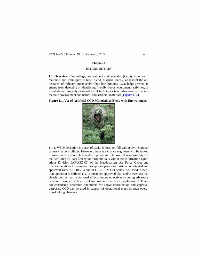
1.1. Overview. Camouflage, concealment and deception (CCD) is the use of
materials and techniques to hide, blend, disguise, decoy, or disrupt the ap-
pearance of military targets and/or their backgrounds. CCD helps prevent an
enemy from detecting or identifying friendly troops, equipment, activities, or
installations. Properly designed CCD techniques take advantage of the im-
mediate environment and natural and artificial materials (Figure 1.1.).
Figure 1.1. Use of Artificial CCD Materials to Blend with Environment.
1.1.1. While deception is a part of CCD, it does not fall within civil engineer
primary responsibilities. However, there is a chance engineers will be tasked
to assist in deception plans and/or operations. The overall responsibility for
the Air Force Military Deception Program falls within the Information Oper-
ations Division (AF/A3Z-CI) of the Headquarters Air Force Cyber and
Space Operations Directorate. Deception operations must be coordinated and
approved IAW AFI 10-704 and/or CJCSI 3211.01 series. An USAF decep-
tion operation is defined as a commander approved plan and/or event(s) that
clearly outline real or notional effects and/or objectives targeting adversary
decision makers. Tactical level training and exercises employing CCD are
not considered deception operations for above coordination and approval
purposes. CCD can be used in support of operational plans through opera-
tional taking channels.
AFH 10-222 Volume 10 18 February 2011 7
1.1.2. Civil Engineer (CE) units and personnel have CCD responsibilities
that should be performed in specific situations. For example, in high threat
areas where the enemy may launch mortar or rocket attacks at the installa-
tion, passive protection measures should be taken to protect high valued tar-
gets, referenced as Deception in support of operations security (DISO).
Some of these measures include dispersing mission essential assets, includ-
ing personnel, and then camouflaging or concealing them from enemy re-
connaissance and surveillance to prevent them from becoming targets. Al-
though, much of this handbook is written to support mobile ground units, the
principles, tactics, techniques, and procedures are relevant to fixed installa-
tions and their assets. Listed below are just a few examples of CE resources
that may require CCD measures and/or dispersal under specific threat condi-
tions.
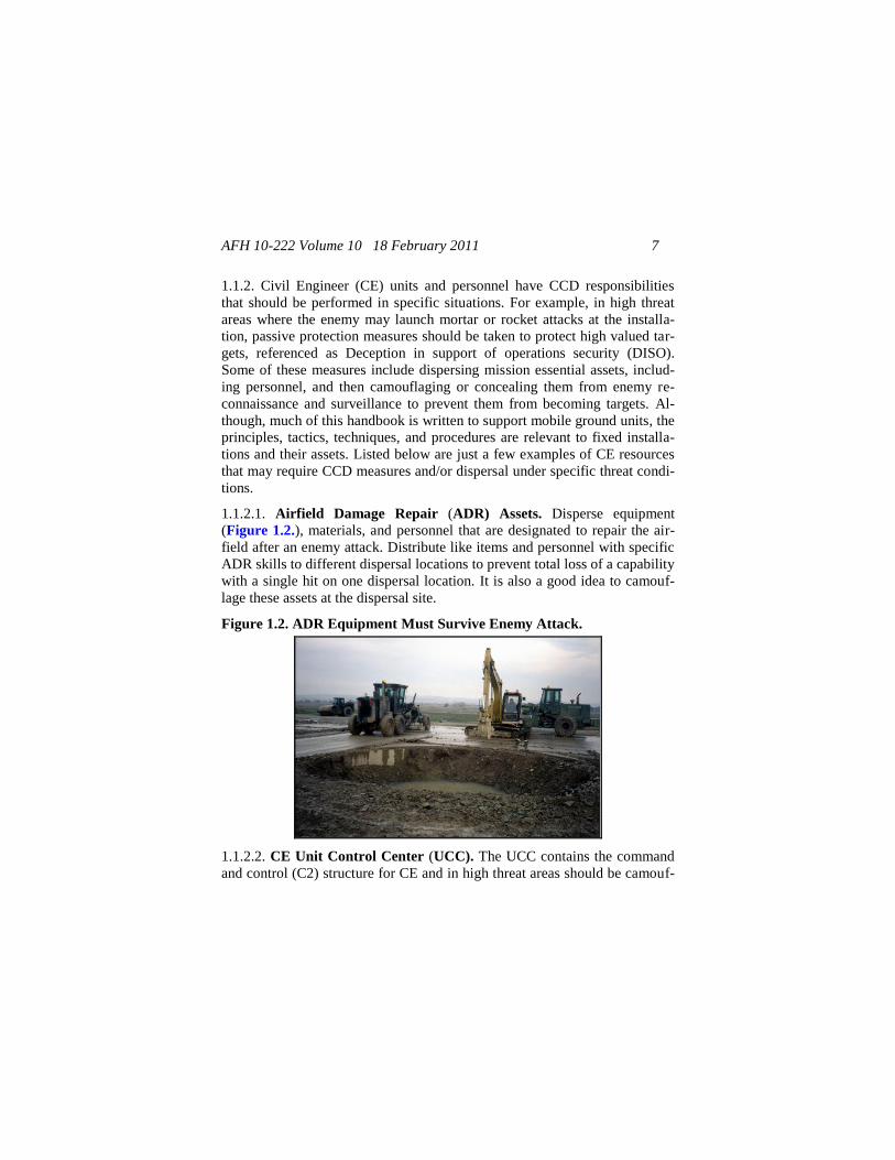
1.1.2.1. Airfield Damage Repair (ADR) Assets. Disperse equipment
(Figure 1.2.), materials, and personnel that are designated to repair the air-
field after an enemy attack. Distribute like items and personnel with specific
ADR skills to different dispersal locations to prevent total loss of a capability
with a single hit on one dispersal location. It is also a good idea to camouf-
lage these assets at the dispersal site.
Figure 1.2. ADR Equipment Must Survive Enemy Attack.
1.1.2.2. CE Unit Control Center (UCC). The UCC contains the command
and control (C2) structure for CE and in high threat areas should be camouf-
AFH 10-222 Volume 10 18 February 2011 8
laged to help ensure survivability of its personnel. In addition, the alternate
UCC should be dispersed far enough from the primary UCC to prevent bomb
damage from an explosion at the primary UCC if it is hit during an attack.
1.1.2.3. Power Plants. Plan to disperse power plants in a high-threat envi-
ronment and interconnect them to ensure some degree of electrical genera-
tion capability is retained after an attack. Use CCD measures on power plant
assets and stand-by generators to protect against targeting by the enemy.
1.1.2.4. Personnel with Special Skills. As mentioned in paragraph 1.1.1.1.,
disperse personnel with special skill-sets to separate locations to prevent loss
of their capabilities with a single hit on one dispersal location. Also, disperse
personnel with the same Air Force specialty to different locations.
1.1.2.5. Firefighting Vehicles. Fires are a major result from enemy attack.
Therefore, disperse and camouflage firefighting vehicles to increase their
chances of survivability.
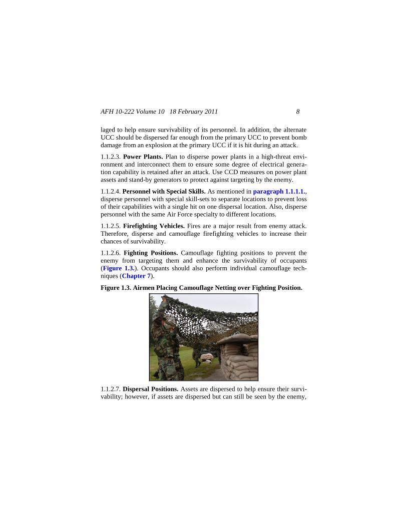
1.1.2.6. Fighting Positions. Camouflage fighting positions to prevent the
enemy from targeting them and enhance the survivability of occupants
(Figure 1.3.). Occupants should also perform individual camouflage tech-
niques (Chapter 7).
Figure 1.3. Airmen Placing Camouflage Netting over Fighting Position.
1.1.2.7. Dispersal Positions. Assets are dispersed to help ensure their survi-
vability; however, if assets are dispersed but can still be seen by the enemy,
AFH 10-222 Volume 10 18 February 2011 9
they can become a target. Therefore, CCD measures are a necessity to help
ensure the assets survive the attack.
1.1.3. To help ensure the installation’s mission continues after an enemy
attack, all units must apply CCD principles to protect friendly forces and
high value assets from enemy weapons and actions. Ignoring a threat's ability
to detect and target high valued targets is shortsighted and dangerous.
Friendly units enhance their survivability capabilities if they are well versed
in CCD principles and techniques.
1.1.4. Increased survivability and mission continuation is the goal of a CCD
plan. A unit commander must encourage each Airman to think of survivabili-
ty and CCD as synonymous terms. Training Airman to recognize this corre-
lation instills a greater appreciation of CCD values.
1.1.5. CCD encompasses individual and unit efforts such as movement, light,
and noise discipline; litter control; dispersal; and deception operations. Each
Airman’s actions must contribute to the unit's overall CCD posture to max-
imize effectiveness.
1.1.6. This handbook is designed to take the reader through the sequential
stages of CCD in hopes of understanding and correctly implementing the
CCD plan. This understanding begins with knowing the threat you are faced
with. Threat familiarization determines the necessity of CCD, and if so, what
CCD measures will be effective. The fundamentals of CCD are discussed to
give the reader the foundation necessary to effectively execute the CCD
plan. Next, the handbook explains how CCD fits in the overall installation’s
defensive operations plan to blind the enemy. Then, suggestions are given to
help determine which assets are high valued targets and how to protect those
targets using CCD. Finally, details are given on how the environment may
affect CCD implementation measures.
1.2. Responsibilities.
1.2.1. Installation Commander. Where applicable, establishes a single,
comprehensive, installation-wide CCD program that supports all units. Typi-
cally, this will be managed by the installation commander’s appointed Mili-
tary Deception Officer and/or NCO (MDO/MDNCO) per AFI 10-704.
AFH 10-222 Volume 10 18 February 2011 10
1.2.1.1. Insert CCD guidance into applicable operations orders, plans, direc-
tives, and similar documents.
1.2.1.2. Assesses intelligence indicators and operational situations to decide
which force protection defense measures to implement and when to imple-
ment them.
1.2.1.3. Ensures all installation units, including tenants, augmenting forces
and geographically separated units (GSUs), participate in the installation
CCD program.
1.2.1.4. Ensure CCD considerations are incorporated into deployment loca-
tion plans and home station facilities and landscaping, if appropriate.
1.2.2. Unit Commanders. Where applicable, unit commanders are responsi-
ble for CCD of their units using established standard operating procedures
(SOPs) and battle drills to guide their efforts. They also identify require-
ments, budget for, obtain, store and maintain unit passive defense operation-
al and training equipment. Unit commanders will ensure CCD efforts are
coordinated with the installation MDO/MDNCO and IAW AFI 10-704, Mili-
tary Deception Program.
1.2.3. Intelligence/Area Air Defense Commander (AADC). Assesses ca-
pabilities of potential enemies and provides timely warning of attack, which
initiates some passive defense measures.
1.2.4. CE Commander. The CE Commander participates in installation
threat and vulnerability assessments with AFOSI, SF, and the Threat Work-
ing Group (TWG) IAW AFI10-245, Antiterrorism (AT). They identify re-
source dispersal sites and provide dispersal information in the CE Contin-
gency Response Plan or the Comprehensive Emergency Management Plan
(CEMP) 10-2. CE Commanders will also direct appropriate CE subject mat-
ter experts to assist the installation MDO/MDNCO planning and/or execu-
tion efforts when requested.
1.2.5. CE Readiness and Emergency Management Flight. Ensures Emer-
gency Management program direction and guidance are included in opera-
tions orders, plans, directive, support agreements, and other installation
planning documents.
AFH 10-222 Volume 10 18 February 2011 11
1.2.5.1. They also manage the passive defense for the CE Commander and
Installation Commander.
1.2.5.2. Assists in passive defense plans and checklists development.
1.2.5.3. Develops, publishes, and maintains the installation CEMP 10-2.
1.2.5.4. Provide procedures and planned actions for conventional attack pro-
tective requirements in the In-garrison Expeditionary Site Plan (IGESP)/
Expeditionary Site Plan (ESP), including CCD operations that identify pro-
cedures on how and where to have camouflage netting, expedient tonedown,
and decoys, including available quantities both in-place and deployable to
the base (AFI10-404, Base Support and Expeditionary Site Planning).
1.2.6. Each Airman. Every Airman is responsible for personal camouflage,
equipment camouflage, and dispersal.
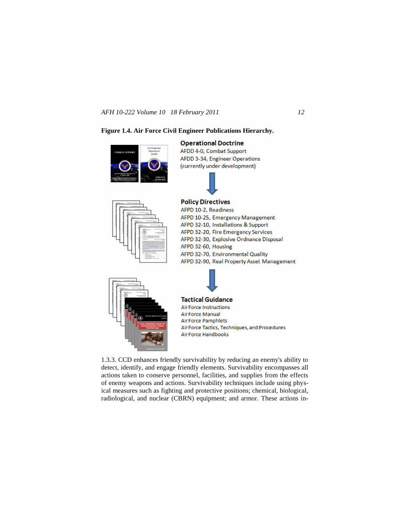
1.3. Doctrinal Considerations. This handbook supports implementation of
Air Force Policy Directive (AFPD) 10-2, Readiness, and contains tactics,
techniques, and procedures (TTPs) for use by civil engineers in supporting
precepts outlined in Air Force Doctrine Document (AFDD) 2-4, Agile Com-
bat Support and AFDD 3-34, Civil Engineer Operations. This relationship is
illustrated in the Air Force CE hierarchy of publications (Figure 1.4.).
1.3.1. One of the imperatives of military doctrine is to conserve friendly
strength for decisive action. Such conservation is aided through sound opera-
tions security (OPSEC) and protection from attack. Protection includes all
actions that make Airmen, equipment, and units difficult to locate.
1.3.2. CCD degrades the effectiveness of enemy reconnaissance, surveil-
lance, and target acquisition (RSTA) capabilities. Skilled observers and so-
phisticated sensors can be defeated by obscuring telltale signs (signatures) of
units on the battlefield. Preventing detection impairs enemy efforts to assess
friendly operational patterns, functions, and capabilities. This describes the
goals and objectives of a DISO effort.
AFH 10-222 Volume 10 18 February 2011 12
Figure 1.4. Air Force Civil Engineer Publications Hierarchy.
1.3.3. CCD enhances friendly survivability by reducing an enemy's ability to
detect, identify, and engage friendly elements. Survivability encompasses all
actions taken to conserve personnel, facilities, and supplies from the effects
of enemy weapons and actions. Survivability techniques include using phys-
ical measures such as fighting and protective positions; chemical, biological,
radiological, and nuclear (CBRN) equipment; and armor. These actions in-
AFH 10-222 Volume 10 18 February 2011 13
clude interrelated tactical countermeasures such as dispersion, movement
techniques, OPSEC, communications security (COMSEC), CCD, and smoke
operations (a form of CCD). Improved survivability from CCD is not re-
stricted to combat operations. Benefits are also derived by denying an enemy
the collection of information about friendly forces during peacetime.
1.3.4. Deception helps mask the real intent of primary combat operations and
aids in achieving surprise. Deception countermeasures can delay effective
enemy reaction by disguising information about friendly intentions, capabili-
ties, objectives, and locations of vulnerable units and facilities. Conversely,
intentionally poor CCD can project misleading information about friendly
operations. Successful tactical deception depends on stringent OPSEC. As
mentioned previously, deception does not fall within CE responsibilities;
however, regarding CCD planning and employment, it should be expected
that engineers will be tasked to assist in deception operations.
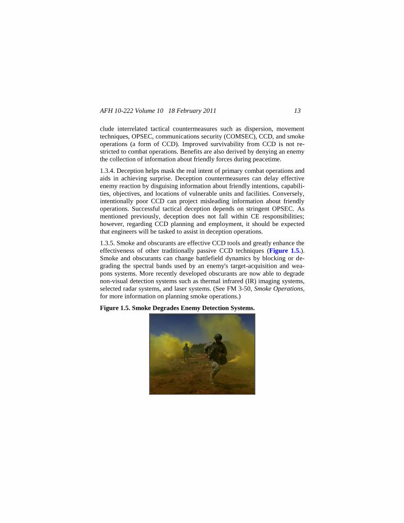
1.3.5. Smoke and obscurants are effective CCD tools and greatly enhance the
effectiveness of other traditionally passive CCD techniques (Figure 1.5.).
Smoke and obscurants can change battlefield dynamics by blocking or de-
grading the spectral bands used by an enemy's target-acquisition and wea-
pons systems. More recently developed obscurants are now able to degrade
non-visual detection systems such as thermal infrared (IR) imaging systems,
selected radar systems, and laser systems. (See FM 3-50, Smoke Operations,
for more information on planning smoke operations.)
Figure 1.5. Smoke Degrades Enemy Detection Systems.
AFH 10-222 Volume 10 18 February 2011 14
1.4. Priorities.
1.4.1. Every Airman and unit has an inherent mission of self-protection and
they should use all CCD means available unless directed otherwise. Howev-
er, CCD countermeasures have become more complicated due to advancing
technology. Commanders must recognize that advanced technologies have:
1.4.1.1. Enhanced the performance of enemy recon and surveillance equip-
ment.
1.4.1.2. Increased an enemy's ability to use electromagnetic (EM) signature
analysis for detecting friendly units.
1.4.1.3. Reduced the time available to apply CCD because units must per-
form nearly all aspects of battlefield operations at an increased speed.
1.4.2. Commanders must prioritize CCD operations when time, camouflage
materials, or other resources are insufficient to provide adequate support.
Considerations for establishing these priorities involve analyzing the mis-
sion, enemy, terrain, weather, troops, time available, and civilian considera-
tions (METT-TC). The following sets forth a METT-TC methodology to
help determine CCD priorities:
1.4.2.1. Mission. The mission is always the first and most important consid-
eration. CCD efforts must enhance the mission but not be so elaborate that
they hinder a unit's ability to accomplish the mission, unless directed other-
wise in support of operational level deception goals and objectives.
1.4.2.2. Enemy. An enemy's RSTA capabilities often influence the camouf-
lage materials and CCD techniques needed to support a unit's mission. Be-
fore beginning a mission, obtain an intelligence analysis from the supporting
intelligence office to identify the enemy's RSTA capabilities.
1.4.2.3. Terrain and Weather. The battlefield terrain generally dictates
what CCD techniques and materials are necessary. Different terrain types or
background environments (urban, mountain, forest, plains, desert, arctic,
etc.) require specific CCD techniques.
1.4.2.4. Airmen. All Airmen must be well trained in CCD techniques that
apply to their mission, unit, and equipment. A change in the environment or
AFH 10-222 Volume 10 18 February 2011 15
the mission often requires additional training on effective techniques. Lead-
ers must also consider the alertness of Airmen. Careless CCD efforts are
ineffective and may disclose a unit's location, degrade its survivability, and
hamper its mission accomplishment. Intelligence analysis should address the
relative detectability of friendly equipment and the target signatures that unit
elements normally project.
1.4.2.5. Time. Time is often a critical consideration. Elaborate CCD may not
be practical in all tactical situations. The type and amount of CCD needed
are impacted by the time a unit occupies a given area, the time available to
employ CCD countermeasures, and the time necessary to remove and reem-
ploy camouflage during unit relocation if necessary. Units should continue to
improve and perfect CCD measures as time allows.
1.4.2.6. Civilian Considerations. From conflict to war and from tactical to
strategic, civilians in the area of operation (AO) may be active or passive
collectors of information. Commanders and their staffs should manage this
collection capability to benefit the command and the mission.
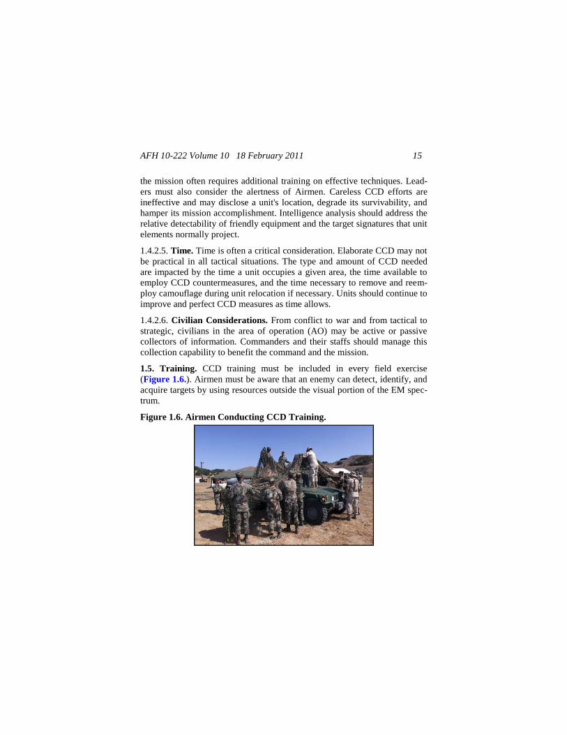
1.5. Training. CCD training must be included in every field exercise
(Figure 1.6.). Airmen must be aware that an enemy can detect, identify, and
acquire targets by using resources outside the visual portion of the EM spec-
trum.
Figure 1.6. Airmen Conducting CCD Training.
AFH 10-222 Volume 10 18 February 2011 16
1.5.1. Individual. Each member of the unit must acquire and maintain criti-
cal CCD skills. These include the ability to analyze and use terrain effective-
ly; to select an individual site properly; and to hide, blend, disguise, disrupt,
and decoy key signatures using natural and artificial materials. See Chapter 7 for individual CCD techniques.
1.5.2. Unit. Unit CCD training refines individual and leader skills, introduc-
es the element of team coordination, and contributes to tactical realism. If
CCD is to conserve friendly strength, it must be practiced with the highest
degree of discipline. The deployment and teardown of camouflage; light,
noise, and communications discipline; and signal security must be practiced
and evaluated in an integrated mission-training environment. CCD profi-
ciency is developed through practicing and incorporating lessons learned
from exercises and operations. Generally, CCD is additive and synergistic
with other defensive measures. CCD enhances unit survivability and increas-
es the likelihood of mission success.
1.5.3. Evaluation. CCD training should be realistic and integrated with
training evaluations. Employ the following techniques to enhance training
evaluations:
1.5.3.1. Have evaluators evaluate their unit's CCD efforts from an enemy's
viewpoint. How a position looks from a few meters away is probably of little
importance. Evaluators should consider the following:
1.5.3.1.1. Could an approaching enemy detect and place aimed weapons fire
on the position?
1.5.3.1.2. From what distance can an enemy detect the position?
1.5.3.1.3. Was there a CCD principle ignored that allowed detection?
Caution
Ensure local environmental considera-
tions are addressed before cutting live
vegetation or foliage in training areas.
AFH 10-222 Volume 10 18 February 2011 17
1.5.3.1.4. Was there a CCD technique that increased the possibility of detec-
tion?
1.5.3.2. Use binoculars, night-vision, or thermal devices when possible to
show a unit how their CCD efforts would appear to an enemy.
1.5.3.3. Use photographs and videotapes, if available, of a unit's deployments
and positions to allow self-evaluation.
1.6. Other Considerations. When employed correctly, expedient CCD
countermeasures are often the most effective means of confusing an enemy.
Along with the standard items and materials listed above, Airmen can use
battlefield by-products, construction materials, and indigenous or locally
procurable items to enhance unit CCD posture. However, as with all CCD
countermeasures, ensure that expedient treatments project the desired signa-
tures to the enemy and do not actually increase the unit's vulnerability to
detection. Expedient CCD countermeasures are also beneficial because the
enemy has less time to study and become familiar with the selected counter-
measures. A sample CCD checklist is provided in Attachment 2 to help
develop a unit’s CCD program.
AFH 10-222 Volume 10 18 February 2011 18
Chapter 2
THREAT
2.1. Overview. The enemy employs a variety of sensors to detect and identi-
fy United States (US) troops, equipment, and supporting installations. These
sensors may be visual, near infrared (NIR), IR, ultraviolet (UV), acoustic, or
multispectral/hyperspectral. They may be employed by dismounted troops or
ground-, air-, or space-mounted platforms. Such platforms are often capable
of supporting multiple sensors. Friendly troops rarely know the specific sen-
sor systems or combination of systems that an enemy employs. When possi-
ble, friendly troops should protect against all known threat surveillance sys-
tems.
2.2. Data Collection. An enemy collects information about US forces for
two basic reasons—target acquisition and intelligence production. Enemy
weapons systems often have sensors that locate and identify targets at long
ranges in precise detail. Troops and units should take actions to hinder the
enemy's target-acquisition process. These actions include all practical CCD
operations expected to reduce the identification of Airmen, units, and facili-
ties.
2.2.1. An enemy uses detection and sensor systems to locate and identify
large formations, logistics centers, communication nodes, and headquarters
(HQ) to predict future activities and intentions.
2.2.2. An enemy uses tactical recon to provide additional information on US
forces' dispositions and the terrain in which they are going to operate. The
enemy's tactical recon also attempts to identify targets for later attack by
long-range artillery, rockets, aircraft, and ground forces.
2.3. Sensor Systems. An enemy uses many different types of electronic sur-
veillance equipment. Sensor systems are classified according to the part of
the EM spectrum in which they operate. An enemy uses detection sensors
that operate in the active or passive mode. Active sensors emit energy that
reflects from targets and is recaptured by the emitting or other nearby sensor,
indicating the presence of a target. Examples of active sensors are sear-
chlights and radar. Passive sensors do not emit energy; they collect energy,
AFH 10-222 Volume 10 18 February 2011 19
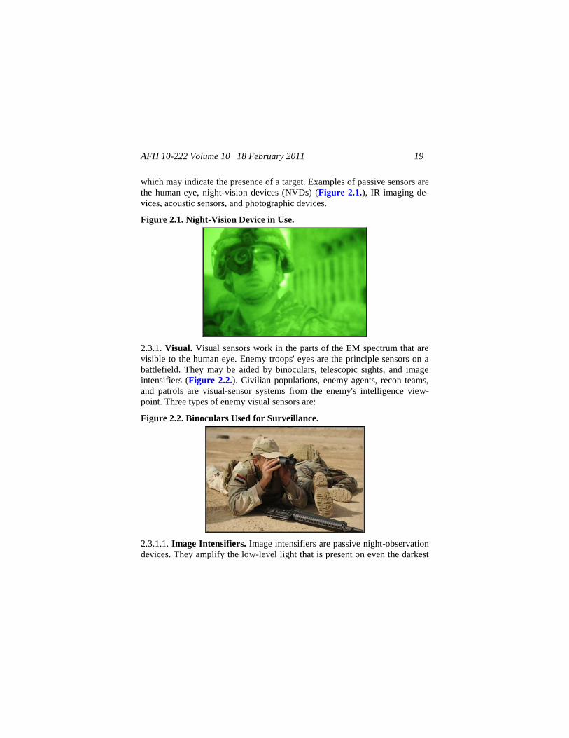
which may indicate the presence of a target. Examples of passive sensors are
the human eye, night-vision devices (NVDs) (Figure 2.1.), IR imaging de-
vices, acoustic sensors, and photographic devices.
Figure 2.1. Night-Vision Device in Use.
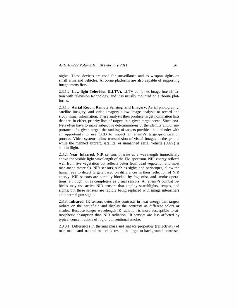
2.3.1. Visual. Visual sensors work in the parts of the EM spectrum that are
visible to the human eye. Enemy troops' eyes are the principle sensors on a
battlefield. They may be aided by binoculars, telescopic sights, and image
intensifiers (Figure 2.2.). Civilian populations, enemy agents, recon teams,
and patrols are visual-sensor systems from the enemy's intelligence view-
point. Three types of enemy visual sensors are:
Figure 2.2. Binoculars Used for Surveillance.
2.3.1.1. Image Intensifiers. Image intensifiers are passive night-observation
devices. They amplify the low-level light that is present on even the darkest
AFH 10-222 Volume 10 18 February 2011 20
nights. These devices are used for surveillance and as weapon sights on
small arms and vehicles. Airborne platforms are also capable of supporting
image intensifiers.
2.3.1.2. Low-light Television (LLTV). LLTV combines image intensifica-
tion with television technology, and it is usually mounted on airborne plat-
forms.
2.3.1.3. Aerial Recon, Remote Sensing, and Imagery. Aerial photography,
satellite imagery, and video imagery allow image analysts to record and
study visual information. These analysts then produce target nomination lists
that are, in effect, priority lists of targets in a given target scene. Since ana-
lysts often have to make subjective determinations of the identity and/or im-
portance of a given target, the ranking of targets provides the defender with
an opportunity to use CCD to impact an enemy's target-prioritization
process. Video systems allow transmission of visual images to the ground
while the manned aircraft, satellite, or unmanned aerial vehicle (UAV) is
still in flight.
2.3.2. Near Infrared. NIR sensors operate at a wavelength immediately
above the visible light wavelength of the EM spectrum. NIR energy reflects
well from live vegetation but reflects better from dead vegetation and most
man-made materials. NIR sensors, such as sights and periscopes, allow the
human eye to detect targets based on differences in their reflection of NIR
energy. NIR sensors are partially blocked by fog, mist, and smoke opera-
tions, although not as completely as visual sensors. An enemy's combat ve-
hicles may use active NIR sensors that employ searchlights, scopes, and
sights; but these sensors are rapidly being replaced with image intensifiers
and thermal gun sights.
2.3.3. Infrared. IR sensors detect the contrasts in heat energy that targets
radiate on the battlefield and display the contrasts as different colors or
shades. Because longer wavelength IR radiation is more susceptible to at-
mospheric absorption than NIR radiation, IR sensors are less affected by
typical concentrations of fog or conventional smoke.
2.3.3.1. Differences in thermal mass and surface properties (reflectivity) of
man-made and natural materials result in target-to-background contrasts.
AFH 10-222 Volume 10 18 February 2011 21
These contrast levels change dramatically over a daily cycle. For example,
operating vehicles and generators, heated buildings and tents, and soldiers
are usually hotter than their background. Also, equipment exposed to direct
sunlight appears hotter than most natural backgrounds. At night, however,
equipment might appear cooler than its background if it is treated with spe-
cial emissivity coatings. In other words, military equipment, particularly
metallic equipment, generally heats up and cools off more quickly than its
background.
2.3.3.2. Sophisticated, passive IR sensors (such as the Forward-Looking
Infrared System [FLIRS]) can be mounted on aircraft. FLIRS sensors pro-
vide aircrews and enemy ground forces with real-time IR imagery that is
displayed on video monitors.
2.3.3.3. Recon aircraft often employ special IR films to record temperature
differences. Due to film processing, however, these systems are subject to
time delays in obtaining the data. Newer versions of this sensor produce non-
film-based images.
2.3.4. Ultraviolet. The UV area is the part of the EM spectrum immediately
below visible light. UV sensors are more important in snow-covered areas,
because snow reflects UV energy well and most white paints and man-made
objects do not reflect UV energy very well. Photographic intelligence sys-
tems with simple UV filters highlight military targets as dark areas against
snow-covered backgrounds. These backgrounds require specially designed
camouflage that provides a high UV reflectance.
2.3.5. Radar. Radar uses high-frequency radio waves to penetrate atmos-
pheric impediments such as fog, mist, and smoke. Radar works by transmit-
ting a very strong burst of radio waves and then receiving and processing the
reflected waves. In general, metal objects reflect radar waves well, while
radar waves are either weakly reflected by or pass through most other ob-
jects. The shape and size of a metal object determine the strength of the re-
flected signal. A large, metal object generally reflects more signal than a
small object. Therefore, large, metal objects can be detected from greater
distances. The method by which the received radio wave is processed deter-
mines the type of radar.
AFH 10-222 Volume 10 18 February 2011 22
2.3.6. Acoustic. The enemy can locate friendly forces through the detection
of noise; therefore, it is important to practice noise discipline where a threat
of detection exists. The three predominant types of acoustical detection sys-
tems are:
2.3.6.1. Human Ear. Every Airman, whether engaged in normal operations
or at a listening post, is an acoustic sensor. However, visual confirmation is
usually preferred.
2.3.6.2. Flash-Sound Ranging. Flash-sound ranging is used against artillery.
Light travels faster than sound, so enemy sound-ranging teams can deter-
mine the distance to a gun tube by accurately measuring the time between
seeing a muzzle flash and hearing the sound. If the sound is detected by two
or more teams, analysts plot the ranges using automated data-processing
computers. The target is located where the plots intersect.
2.3.6.3. Ground-Based Microphone Array. Ground-based microphone-
array systems allow listeners to record acoustic signatures and accurately
triangulate their positions.
2.3.7. Radio. Threat forces make a great effort to search for, detect, and lo-
cate the sources of US radio communications. They use various direction-
finding techniques to locate opposing emitters. Once an emitter is detected,
an enemy can take a number of actions, ranging from simply intercepting the
transmissions to jamming or targeting the emitter for destruction.
2.3.8. Multispectral and Hyperspectral. Recent advancements in sensor
acquisition and information-processing technologies have fostered the ad-
vent of multispectral and hyperspectral sensors. These sensors can acquire a
target by collecting data through scanning a few broad-band channels or the
continuous portion of the EM spectrum
2.4. CCD versus Threat Sensors. Target acquisition can be accomplished
by a variety of sensors that operate throughout the EM spectrum. This poses
a challenge in CCD planning and employment—determining which enemy
sensor(s) that CCD operations should be designed to defeat. Unfortunately,
no single answer is correct for all situations. Unit commanders without spe-
cific guidance from higher echelons assess their tactical situation and plan
AFH 10-222 Volume 10 18 February 2011 23
CCD operations accordingly. If intelligence data indicate that an enemy will
use visual sensors for recon and target acquisition, then visual countermea-
sures must be employed. For IR or radar sensors, countermeasures that are
effective in those spectra must be employed. If a multispectral or hyperspec-
tral threat is anticipated, CCD operations are conducted to protect a unit in
its most vulnerable EM bandwidths. Very few available camouflage mate-
rials or techniques provide complete broadband protection.
AFH 10-222 Volume 10 18 February 2011 24
Chapter 3
FUNDAMENTALS
3.1. Overview. To remain a viable force on the battlefield, units must under-
stand CCD fundamentals because they are essential to survivability. To de-
sign and place effective CCD, Airmen must constantly consider an enemy's
point of view. (What will it see? What characteristics will its sensors detect?)
Placing a low priority on CCD because of time constraints, minimal re-
sources, or inconvenience could result in mission failure and unnecessary
loss of life.
3.2. Avoiding Detection. The primary goal of CCD is to avoid enemy detec-
tion; however, this is not always feasible. In some cases, CCD may succeed
by merely preventing an enemy from identifying a target. Simply avoiding
identification is often sufficient to increase survivability. The following sev-
en rules are critical when considering how to avoid detection or identifica-
tion:
3.2.1. Identify the enemy's detection capabilities.
3.2.2. Avoid detection by the enemy's routine surveillance.
3.2.3. Take countermeasures against the enemy's sensors.
3.2.4. Employ realistic, CCD countermeasures.
3.2.5. Minimize movement.
3.2.6. Use decoys properly.
3.2.7. Avoid predictable operational patterns.
3.3. Identifying the Threat. Obtain as much information as possible about
an enemy's surveillance capability (see Chapter 2). Intelligence preparation
of the battlefield (IPB) should:
3.3.1. Include the sensors that an enemy may use in a particular AO.
3.3.2. Include information on the enemy's tactical employment of the sen-
sors, if possible.
AFH 10-222 Volume 10 18 February 2011 25
3.3.3. Assess the impact of the enemy's surveillance potential on the target
under consideration. This assessment varies with the relative positions of the
sensor and the target on the battlefield, the role of the target, and the physical
characteristics of the sensor and the target.
3.4. Avoiding Detection by Routine Surveillance. Sophisticated sensors
often have narrow fields of view. Furthermore, sensors can be very expen-
sive and are unlikely to be deployed in such numbers as to enable coverage
of the entire battlefield at all times.
3.4.1. Sophisticated sensors are most likely to be deployed in those areas
where an enemy suspects that friendly targets are deployed. The enemy may
suspect that an area contains targets because of detection by less sophisti-
cated, wider-coverage sensors or because of tactical analysis. Therefore, an
important aspect of remaining undetected is to avoid detection by routine
enemy surveillance.
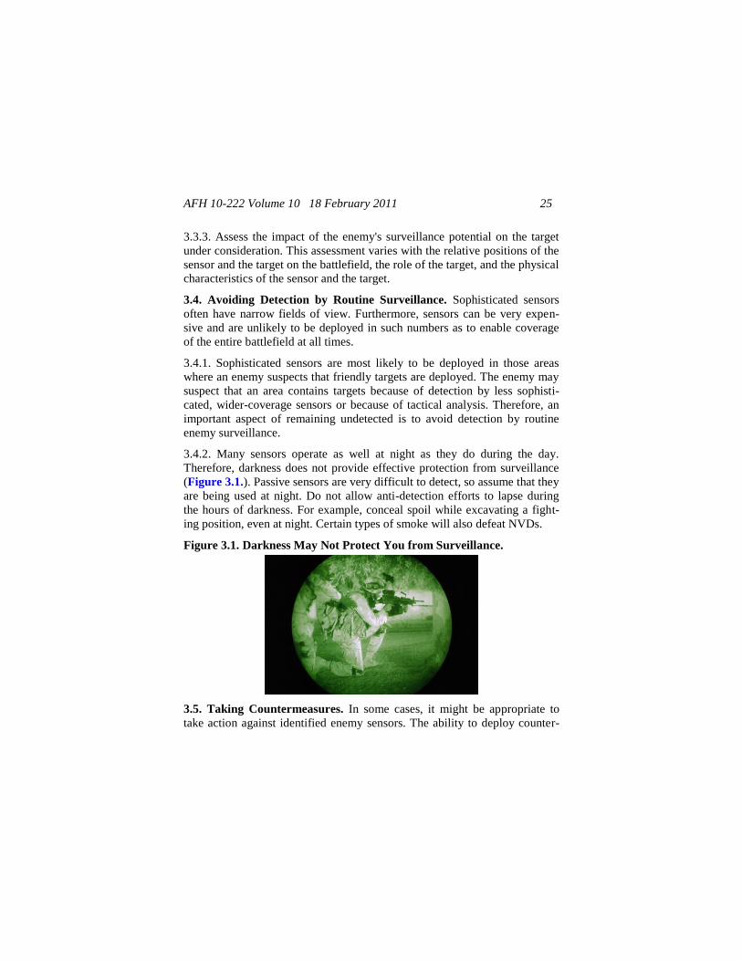
3.4.2. Many sensors operate as well at night as they do during the day.
Therefore, darkness does not provide effective protection from surveillance
(Figure 3.1.). Passive sensors are very difficult to detect, so assume that they
are being used at night. Do not allow anti-detection efforts to lapse during
the hours of darkness. For example, conceal spoil while excavating a fight-
ing position, even at night. Certain types of smoke will also defeat NVDs.
Figure 3.1. Darkness May Not Protect You from Surveillance.
3.5. Taking Countermeasures. In some cases, it might be appropriate to
take action against identified enemy sensors. The ability to deploy counter-
AFH 10-222 Volume 10 18 February 2011 26
measures depends on a number of factors—the effective range of friendly
weapons, the distance to enemy sensors, and the relative cost in resources
versus the benefits of preventing the enemy's use of the sensor. An additional
factor to consider is that the countermeasure itself may provide an enemy
with an indication of friendly intentions.
3.6. Employing Realistic CCD. The more closely a target resembles its
background, the more difficult it is for an enemy to distinguish between the
two. Adhering to this fundamental CCD principle requires awareness of the
surroundings, proper CCD skills, and the ability to identify target EM signa-
tures that enemy sensors will detect.
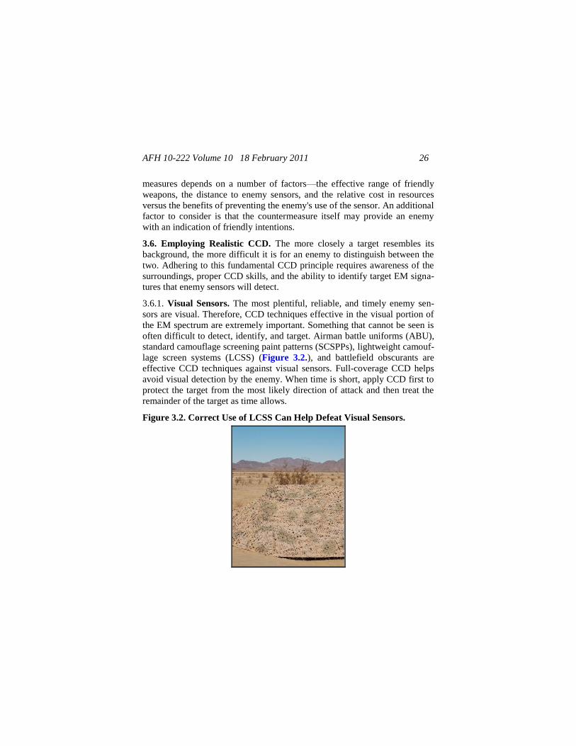
3.6.1. Visual Sensors. The most plentiful, reliable, and timely enemy sen-
sors are visual. Therefore, CCD techniques effective in the visual portion of
the EM spectrum are extremely important. Something that cannot be seen is
often difficult to detect, identify, and target. Airman battle uniforms (ABU),
standard camouflage screening paint patterns (SCSPPs), lightweight camouf-
lage screen systems (LCSS) (Figure 3.2.), and battlefield obscurants are
effective CCD techniques against visual sensors. Full-coverage CCD helps
avoid visual detection by the enemy. When time is short, apply CCD first to
protect the target from the most likely direction of attack and then treat the
remainder of the target as time allows.
Figure 3.2. Correct Use of LCSS Can Help Defeat Visual Sensors.
AFH 10-222 Volume 10 18 February 2011 27
3.6.2. NIR Sensors. NIR sights are effective at shorter ranges (typically 900
meters) than enemy main guns. While red filters help preserve night vision,
they cannot prevent NIR from detecting light from long distances. Therefore,
careful light discipline is an important countermeasure to NIR sensors and
visual sensors (such as image intensifiers). ABUs, SCSPPs LCSS, and bat-
tlefield obscurants are designed to help defeat NIR sensors.
3.6.3. IR Sensors. Natural materials and terrain shield heat sources from IR
sensors and break up the shape of cold and warm military targets viewed on
IR sensors. Do not raise vehicle hoods to break windshield glare because this
exposes a hot spot for IR detection. Even if the IR system is capable of locat-
ing a target, the target's actual identity can still be disguised. Avoid building
unnecessary fires. Use vehicle heaters only when necessary. ABU dyes,
LCSSs, IR-defeating obscurants, and chemical-resistant paints help break up
IR signatures; but they will not defeat IR sensors.
3.6.4. UV Sensors. UV sensors are a significant threat in snow-covered
areas. Winter paint patterns, the arctic LCSS, and terrain masking are critical
means for defending against these sensors. Any kind of smoke will defeat
UV sensors. Field-expedient countermeasures, such as constructing snow
walls, also provide a means of defeating UV sensors.
3.6.5. Radar. AF engineer forces are vulnerable when an enemy uses Mov-
ing-Target Indicator (MTI) and imaging radars. Mission dictates the appro-
priate defense, while techniques depend on the equipment available.
3.6.5.1. MTI. MTI radar is a threat to ground forces near a battle area. Ra-
dar-reflecting metal on uniforms has been reduced, and Kevlar helmets and
body armor are now radar-transparent. Plastic canteens are standard issue,
and buttons and other nonmetal fasteners have replaced metal snaps on most
field uniforms. An Airman wearing only the ABU cannot be detected until
he is very close to MTI radar.
3.6.5.1.1. Airmen still carry metal objects (ammunition, magazines, wea-
pons, tools) to accomplish their mission, and most radars can detect these
items. Therefore, movement discipline is very important. Moving by covered
routes (terrain masking) prevents radar detection. Slow, deliberate move-
AFH 10-222 Volume 10 18 February 2011 28
ments across areas exposed to radar coverage helps avoid detection by MTI
radar.
3.6.5.1.2. Vehicles are large radar-reflecting targets, and a skilled MTI oper-
ator can even identify the type of vehicle. Moving vehicles can be detected
by MTI radar from 20 kilometers, but travelling by covered routes helps pro-
tect against surveillance.
3.6.5.2. Imaging. Imaging radar is not a threat to individual Airmen. Con-
cealing vehicles behind earth, masonry walls, or dense foliage effectively
screens them from imaging radar. Light foliage may provide complete visual
concealment; however, it is sometimes totally transparent to imaging radar.
When properly deployed, the LCSS effectively scatters the beam of imaging
radar.
3.6.6. Acoustic Sensors. Noise discipline defeats detection by the human
ear. Pyrotechnics or loudspeakers can screen noise, cover inherently noisy
activities, and confuse sound interpretation.
3.6.7. Radio Sensors. The best way to prevent an enemy from locating radio
transmitters is to minimize transmissions, protect transmissions from enemy
interception, and practice good radiotelephone-operator (RATELO) proce-
dures. Preplanning message traffic, transmitting as quickly as possible, and
using alternate communication means whenever possible ensure that trans-
missions are minimized. To prevent the enemy from intercepting radio
communications, change the radio frequencies and use low-power transmis-
sions, terrain masking, or directional or short-range antennas.
3.7. Minimizing Movement. Movement attracts the enemy's attention and
produces a number of signatures (tracks, noise, hot spots, dust). In operations
that inherently involve movement (such as offensive operations), plan, dis-
cipline, and manage movement so that signatures are reduced as much as
possible.
3.8. Using Decoys. As mentioned previously, decoys fall outside the respon-
sibility of AF engineers; however, engineers may be tasked to assist with
decoy operations and therefore they should be aware of their use.
AFH 10-222 Volume 10 18 February 2011 29
3.8.1. Use decoys to confuse an enemy. The goal is to divert enemy re-
sources into reporting or engaging false targets. An enemy who has mista-
kenly identified decoys as real targets is less inclined to search harder for the
actual, well-hidden targets. The keys to convincing an enemy that it has
found the real target are:
3.8.1.1. Decoy fidelity (realism), which refers to how closely the multispec-
tral decoy signature represents the target signature.
3.8.1.2. Deployment location, which refers to whether or not a decoy is dep-
loyed so that the enemy will recognize it as typical for that target type. For
example, a decoy jet is not properly located if it is placed in the middle of a
motor pool.
3.8.2. A high-fidelity decoy in a plausible location often fools an enemy into
believing that it has acquired the real target. Deploying low-fidelity decoys,
however, carries an associated risk. If an enemy observes a decoy and im-
mediately recognizes it as such, it will search harder for the real target since
decoys are generally deployed in the same vicinity as the real targets. Plausi-
ble, high-fidelity decoys specifically designed to draw enemy fire away from
real targets should be deployed to closely represent the multispectral signa-
tures of the real targets. Properly deployed decoys have been proven in oper-
ational employment and experimental field tests to be among the most effec-
tive of all CCD techniques.
3.9. Applying Recognition Factors. To camouflage effectively, continually
consider the threat's viewpoint. Prevent patterns in anti-detection counter-
measures by applying the following recognition factors to tactical situations.
These factors describe a target's contrast with its background. If possible,
collect multispectral imagery to determine which friendly target signatures
are detectable to enemy sensors.
3.9.1. Reflectance. Reflectance is the amount of energy returned from a tar-
get's surface as compared to the energy striking the surface. Reflectance is
generally described in terms of the part of the EM spectrum in which the
reflection occurs:
AFH 10-222 Volume 10 18 February 2011 30
3.9.1.1. Visual reflectance is characterized by the color of a target. Color
contrast can be important, particularly at close ranges and in homogeneous
background environments such as snow or desert terrain. The longer the
range, the less important color becomes. At very long ranges, all colors tend
to merge into a uniform tone. Also, the human eye cannot discriminate color
in poor light.
3.9.1.2. Temperature reflectance is the thermal energy reflected by a target
(except when the thermal energy of a target is self-generated, as in the case
of a hot engine). IR imaging sensors measure and detect differences in tem-
perature-reflectance levels (known as thermal contrast).
3.9.1.3. Radar-signal reflectance is the part of the incoming radio waves that
is reflected by a target. Radar sensors detect differences in a target's reflected
radar return and that of the background. Since metal is an efficient radio-
wave reflector and metals are still an integral part of military equipment,
radar return is an important reflectance factor.
3.9.2. Shape. Natural background is random, and most military equipment
has regular features with hard, angular lines. Even an erected camouflage net
takes on a shape with straight-line edges or smooth curves between support
points. An enemy can easily see silhouetted targets, and its sensors can
detect targets against any background unless their shape is disguised or dis-
rupted. Size, which is implicitly related to shape, can also distinguish a target
from its background.
3.9.3. Shadow. Shadow can be divided into two types:
3.9.3.1. A cast shadow is a silhouette of an object projected against its back-
ground. It is the more familiar type and can be highly conspicuous. In desert
environments, a shadow cast by a target can be more conspicuous than the
target itself.
3.9.3.2. A contained shadow is the dark pool that forms in a permanently
shaded area. Examples are the shadows inside a trench, inside an open fight-
ing position, or under a vehicle. Contained shadows show up much darker
than their surroundings and are easily detected by an enemy.
AFH 10-222 Volume 10 18 February 2011 31
3.9.4. Movement. Movement always attracts attention against a stationary
background. Slow, regular movement is usually less obvious than fast, errat-
ic movement.
3.9.5. Noise. Noise and acoustic signatures produced by military activities
and equipment are recognizable to the enemy.
3.9.6. Texture. A rough surface appears darker than a smooth surface, even
if both surfaces are the same color. For example, vehicle tracks change the
texture of the ground by leaving clearly visible track marks. This is particu-
larly true in undisturbed or homogeneous environments, such as a desert or
virgin snow, where vehicle tracks are highly detectable. In extreme cases, the
texture of glass or other very smooth surfaces causes a shine that acts as a
beacon. Under normal conditions, very smooth surfaces stand out from the
background. Therefore, eliminating shine must be a high priority in CCD.
3.9.7. Patterns. Rows of vehicles and stacks of war materiel create equip-
ment patterns that are easier to detect than random patterns of dispersed
equipment. Equipment patterns should be managed to use the surroundings
for vehicle and equipment dispersal. Equipment dispersal should not be im-
plemented in such a way that it reduces a unit's ability to accomplish its mis-
sion.
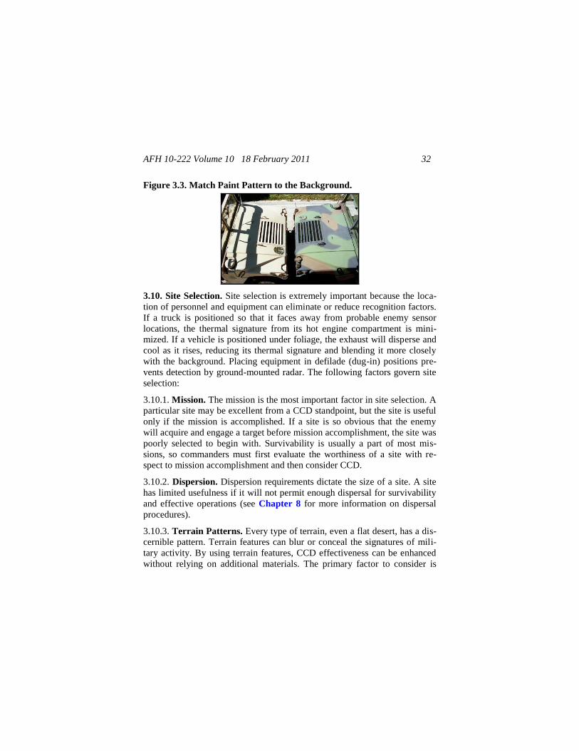
3.9.7.1. Equipment paint patterns often differ considerably from background
patterns (Figure 3.3.). The critical relationships that determine the contrast
between a piece of equipment and its background are the distance between
the observer and the equipment and the distance between the equipment and
its background. Since these distances usually vary, it is difficult to paint
equipment with a pattern that always allows it to blend with its background.
As such, no single pattern is prescribed for all situations. Field observations
provide the best match between equipment and background.
3.9.7.2. The overall terrain pattern and the signatures produced by military
activity on the terrain are important recognition factors. If a unit's presence is
to remain unnoticed, it must match the signatures produced by stationary
equipment, trucks, and other activities with the terrain pattern. Careful atten-
tion must also be given to vehicle tracks and their affect on the local terrain
during unit ingress, occupation, and egress.
AFH 10-222 Volume 10 18 February 2011 32
Figure 3.3. Match Paint Pattern to the Background.
3.10. Site Selection. Site selection is extremely important because the loca-
tion of personnel and equipment can eliminate or reduce recognition factors.
If a truck is positioned so that it faces away from probable enemy sensor
locations, the thermal signature from its hot engine compartment is mini-
mized. If a vehicle is positioned under foliage, the exhaust will disperse and
cool as it rises, reducing its thermal signature and blending it more closely
with the background. Placing equipment in defilade (dug-in) positions pre-
vents detection by ground-mounted radar. The following factors govern site
selection:
3.10.1. Mission. The mission is the most important factor in site selection. A
particular site may be excellent from a CCD standpoint, but the site is useful
only if the mission is accomplished. If a site is so obvious that the enemy
will acquire and engage a target before mission accomplishment, the site was
poorly selected to begin with. Survivability is usually a part of most mis-
sions, so commanders must first evaluate the worthiness of a site with re-
spect to mission accomplishment and then consider CCD.
3.10.2. Dispersion. Dispersion requirements dictate the size of a site. A site
has limited usefulness if it will not permit enough dispersal for survivability
and effective operations (see Chapter 8 for more information on dispersal
procedures).
3.10.3. Terrain Patterns. Every type of terrain, even a flat desert, has a dis-
cernible pattern. Terrain features can blur or conceal the signatures of mili-
tary activity. By using terrain features, CCD effectiveness can be enhanced
without relying on additional materials. The primary factor to consider is
AFH 10-222 Volume 10 18 February 2011 33
whether using the site will disturb the terrain pattern enough to attract an
enemy's attention. The goal is not to disturb the terrain pattern at all. Any
change in an existing terrain pattern will indicate the presence of activity.
Terrain patterns have distinctive characteristics that are necessary to pre-
serve. The five general terrain patterns are:
3.10.3.1. Agricultural. Agricultural terrain has a checkerboard pattern when
viewed from aircraft. This is a result of the different types of crops and vege-
tation found on most farms.
3.10.3.2. Urban. Urban terrain is characterized by uniform rows of housing
with interwoven streets and interspersed trees and shrubs.
3.10.3.3. Wooded. Woodlands are characterized by natural, irregular fea-
tures, unlike the geometric patterns of agricultural and urban terrains.
3.10.3.4. Barren. Barren terrain presents an uneven, irregular work of nature
without the defined patterns of agricultural and urban areas. Desert environ-
ments are examples of barren terrain.
3.10.3.5. Arctic. Arctic terrain is characterized by snow and ice coverage.
3.11. CCD Discipline. CCD discipline is avoiding an activity that changes
the appearance of an area or reveals the presence of military equipment.
CCD discipline is a continuous necessity that applies to every Airman. If the
prescribed visual and audio routines of CCD discipline are not observed, the
entire CCD effort may fail. Vehicle tracks, spoil, and debris are the most
common signs of military activity. Their presence can negate all efforts of
proper placement and concealment.
3.11.1. CCD discipline denies an enemy the indications of a unit's location or
activities by minimizing disturbances to a target area. To help maintain unit
viability, a unit must integrate all available CCD means into a cohesive plan.
CCD discipline involves regulating light, heat, noise, spoil, trash, and
movement. Successful CCD discipline depends largely on the actions of in-
dividual Airmen. Some of these actions may not be easy on an Airman, but
failure to observe CCD discipline could defeat an entire unit's CCD efforts
and possibly impact the unit's survivability and mission success.
AFH 10-222 Volume 10 18 February 2011 34
3.11.2. SOPs prescribing CCD procedures aid in enforcing CCD discipline,
and they should:
3.11.2.1. List specific responsibilities for enforcing established CCD coun-
termeasures and discipline.
3.11.2.2. Detail procedures for individual and unit conduct in assembly areas
or other situations that may apply to the specific unit.
3.11.3. Units should have frequent CCD training sessions. CCD discipline is
a continuous requirement that calls for strong leadership, which produces a
disciplined CCD consciousness throughout the entire unit.
3.11.4. Light and Heat. Light and heat discipline, though important at all
times, is crucial at night. As long as visual observation remains a primary
recon method, concealing light signatures remains an important CCD coun-
termeasure. Lights that are not blacked out at night can be observed at great
distances. For example, the human eye can detect camp fires from 8 kilome-
ters and vehicle lights from 20 kilometers. Threat surveillance can also
detect heat from engines, stoves, and heaters from great distances. When
moving at night, vehicles in the forward combat area should use ground
guides and blackout lights. When using heat sources is unavoidable, use ter-
rain masking, exhaust baffling, and other techniques to minimize thermal
signatures of fires and stoves.
3.11.5. Noise. Individuals should avoid or minimize actions that produce
noise. For example, muffle generators by using shields or terrain masking or
place them in defilade positions. Operate communications equipment at the
lowest possible level that allows them to be heard and understood. Depend-
ing on the terrain and atmospheric conditions, noise can travel great dis-
tances and reveal a unit's position to an enemy.
3.11.6. Spoil. The prompt and complete policing of debris and spoil is an
essential CCD consideration. Proper spoil discipline removes a key signature
of a unit's current or past presence in an area.
3.11.7. Track. Vehicle tracks are clearly visible from the air, particularly in
selected terrain. Therefore, track and movement discipline is essential. Use
existing roads and tracks as much as possible. When using new paths, ensure
AFH 10-222 Volume 10 18 February 2011 35
that they fit into the existing terrain's pattern. Minimize, plan, and coordinate
all movement; and take full advantage of cover and dead space.
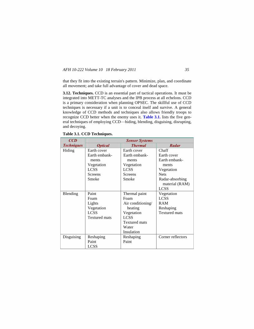
3.12. Techniques. CCD is an essential part of tactical operations. It must be
integrated into METT-TC analyses and the IPB process at all echelons. CCD
is a primary consideration when planning OPSEC. The skillful use of CCD
techniques is necessary if a unit is to conceal itself and survive. A general
knowledge of CCD methods and techniques also allows friendly troops to
recognize CCD better when the enemy uses it. Table 3.1. lists the five gen-
eral techniques of employing CCD—hiding, blending, disguising, disrupting,
and decoying.
Table 3.1. CCD Techniques.
CCD Techniques
Sensor Systems Optical Thermal Radar
Hiding Earth cover
Earth embank-
ments
Vegetation
LCSS
Screens
Smoke
Earth cover
Earth embank-
ments
Vegetation
LCSS
Screens
Smoke
Chaff
Earth cover
Earth embank-
ments
Vegetation
Nets
Radar-absorbing
material (RAM)
LCSS
Blending Paint
Foam
Lights
Vegetation
LCSS
Textured mats
Thermal paint
Foam
Air conditioning/
heating
Vegetation
LCSS
Textured mats
Water
Insulation
Vegetation
LCSS
RAM
Reshaping
Textured mats
Disguising Reshaping
Paint
LCSS
Reshaping
Paint
Corner reflectors
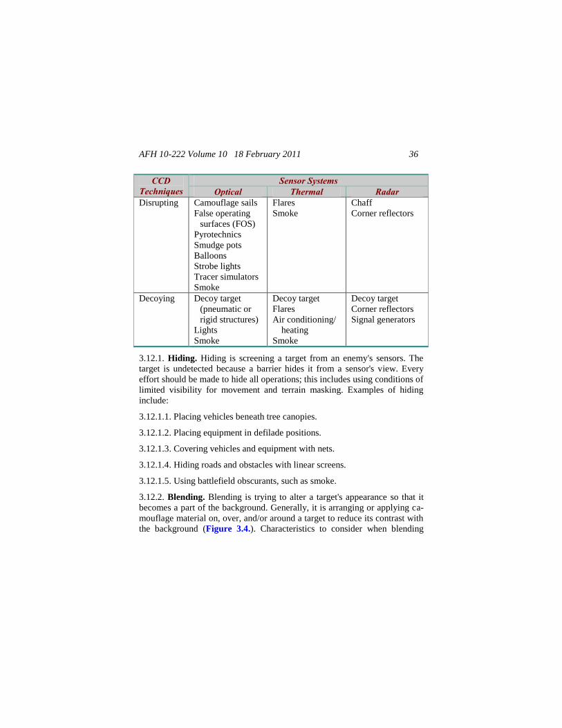
AFH 10-222 Volume 10 18 February 2011 36
CCD Techniques
Sensor Systems Optical Thermal Radar
Disrupting Camouflage sails
False operating
surfaces (FOS)
Pyrotechnics
Smudge pots
Balloons
Strobe lights
Tracer simulators
Smoke
Flares
Smoke
Chaff
Corner reflectors
Decoying Decoy target
(pneumatic or
rigid structures)
Lights
Smoke
Decoy target
Flares
Air conditioning/
heating
Smoke
Decoy target
Corner reflectors
Signal generators
3.12.1. Hiding. Hiding is screening a target from an enemy's sensors. The
target is undetected because a barrier hides it from a sensor's view. Every
effort should be made to hide all operations; this includes using conditions of
limited visibility for movement and terrain masking. Examples of hiding
include:
3.12.1.1. Placing vehicles beneath tree canopies.
3.12.1.2. Placing equipment in defilade positions.
3.12.1.3. Covering vehicles and equipment with nets.
3.12.1.4. Hiding roads and obstacles with linear screens.
3.12.1.5. Using battlefield obscurants, such as smoke.
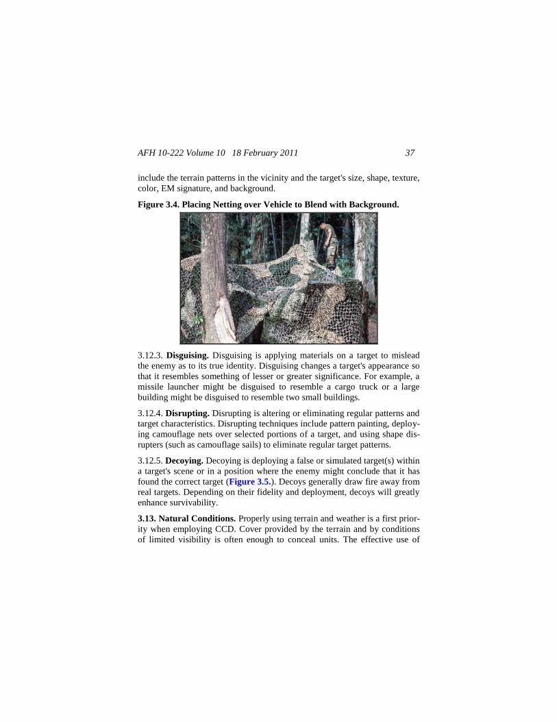
3.12.2. Blending. Blending is trying to alter a target's appearance so that it
becomes a part of the background. Generally, it is arranging or applying ca-
mouflage material on, over, and/or around a target to reduce its contrast with
the background (Figure 3.4.). Characteristics to consider when blending
AFH 10-222 Volume 10 18 February 2011 37
include the terrain patterns in the vicinity and the target's size, shape, texture,
color, EM signature, and background.
Figure 3.4. Placing Netting over Vehicle to Blend with Background.
3.12.3. Disguising. Disguising is applying materials on a target to mislead
the enemy as to its true identity. Disguising changes a target's appearance so
that it resembles something of lesser or greater significance. For example, a
missile launcher might be disguised to resemble a cargo truck or a large
building might be disguised to resemble two small buildings.
3.12.4. Disrupting. Disrupting is altering or eliminating regular patterns and
target characteristics. Disrupting techniques include pattern painting, deploy-
ing camouflage nets over selected portions of a target, and using shape dis-
rupters (such as camouflage sails) to eliminate regular target patterns.
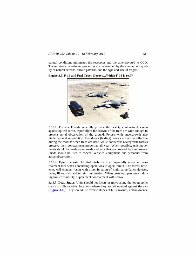
3.12.5. Decoying. Decoying is deploying a false or simulated target(s) within
a target's scene or in a position where the enemy might conclude that it has
found the correct target (Figure 3.5.). Decoys generally draw fire away from
real targets. Depending on their fidelity and deployment, decoys will greatly
enhance survivability.
3.13. Natural Conditions. Properly using terrain and weather is a first prior-
ity when employing CCD. Cover provided by the terrain and by conditions
of limited visibility is often enough to conceal units. The effective use of
AFH 10-222 Volume 10 18 February 2011 38
natural conditions minimizes the resources and the time devoted to CCD.
The terrain's concealment properties are determined by the number and qual-
ity of natural screens, terrain patterns, and the type and size of targets.
Figure 3.5. F-16 and Fuel Truck Decoys…Which F-16 is real?
3.13.1. Forests. Forests generally provide the best type of natural screen
against optical recon, especially if the crowns of the trees are wide enough to
prevent aerial observation of the ground. Forests with undergrowth also
hinder ground observation. Deciduous (leafing) forests are not as effective
during the months when trees are bare, while coniferous (evergreen) forests
preserve their concealment properties all year. When possible, unit move-
ments should be made along roads and gaps that are covered by tree crowns.
Shade should be used to conceal vehicles, equipment, and personnel from
aerial observation.
3.13.2. Open Terrain. Limited visibility is an especially important con-
cealment tool when conducting operations in open terrain. The threat, how-
ever, will conduct recon with a combination of night-surveillance devices,
radar, IR sensors, and terrain illumination. When crossing open terrain dur-
ing limited visibility, supplement concealment with smoke.
3.13.3. Dead Space. Units should not locate or move along the topographic
crests of hills or other locations where they are silhouetted against the sky
(Figure 3.6.). They should use reverse slopes of hills, ravines, embankments,
AFH 10-222 Volume 10 18 February 2011 39
and other terrain features as screens to avoid detection by ground-mounted
sensors. IPB concealment and terrain overlays should identify areas of dead
space. If overlays are not available, use the line-of-sight (LOS) method to
identify areas of dead space.
Figure 3.6. Avoid Being Silhouetted Against the Sky.
3.13.4. Weather. Conditions of limited visibility (fog, rain, snowfall) ham-
per recon by optical sensors. Dense fog is impervious to visible sensors and
some thermal sensors, making many threat night-surveillance devices unusa-
ble. Dense fog and clouds are impenetrable to thermal sensors (IR). Rain,
snow, and other types of precipitation hinder optical, thermal, and radar sen-
sors.
3.13.5. Smoke. Smoke is an effective CCD tool when used by itself or with
other CCD techniques. It can change the dynamics of a battle by blocking or
degrading the spectral bands that an enemy's target-acquisition and weapons
systems use, including optical and thermal bands.
3.14. Materials. Using natural conditions and materials is the first CCD
priority, but using manmade materials can greatly enhance CCD efforts.
Available materials include pattern-painted equipment, camouflage nets
(LCSS), radar-absorbing paint (RAP), RAM, FOSs, vegetation, expedient
paint, decoys, and battlefield by-products (construction materials, dirt).
3.14.1. Pattern Paint. Pattern-painted vehicles blend well with the back-
ground and can hide from optical sensors better than those painted a solid,
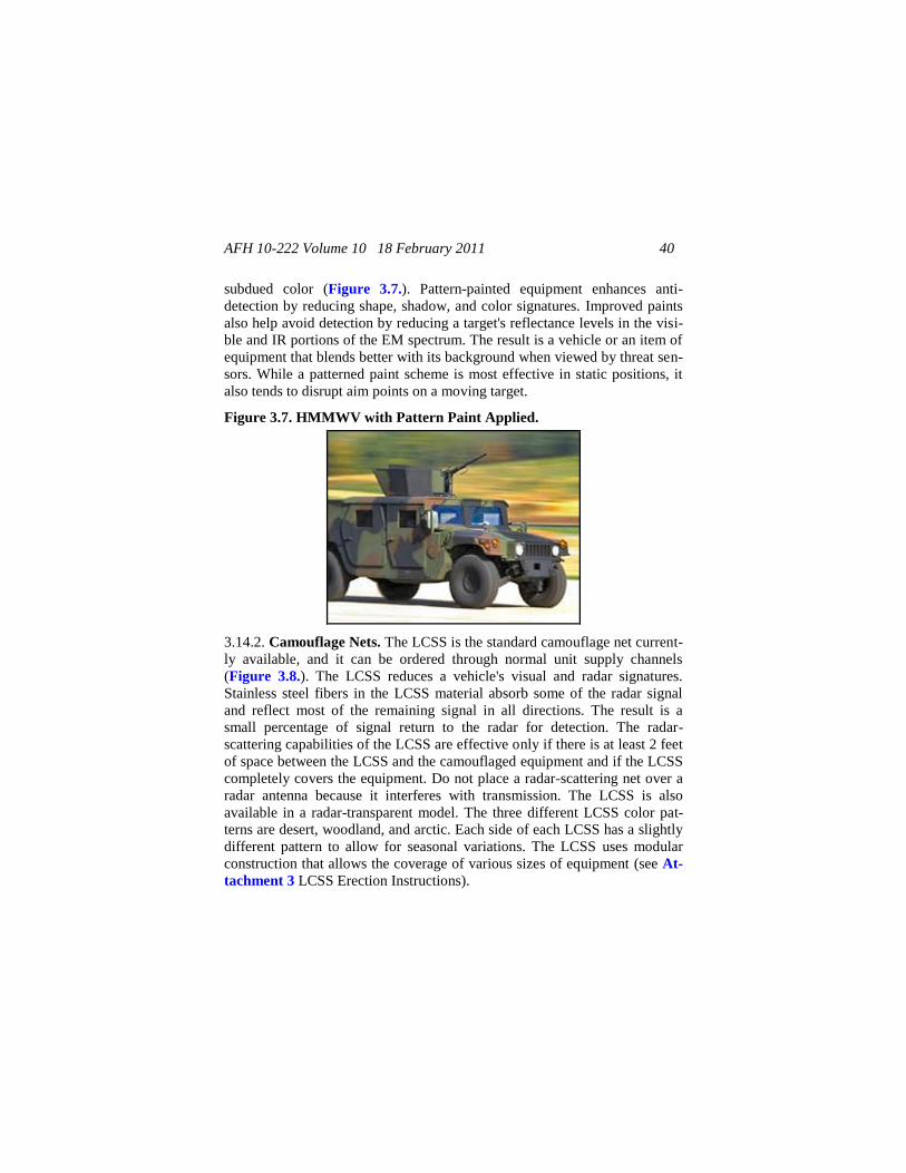
AFH 10-222 Volume 10 18 February 2011 40
subdued color (Figure 3.7.). Pattern-painted equipment enhances anti-
detection by reducing shape, shadow, and color signatures. Improved paints
also help avoid detection by reducing a target's reflectance levels in the visi-
ble and IR portions of the EM spectrum. The result is a vehicle or an item of
equipment that blends better with its background when viewed by threat sen-
sors. While a patterned paint scheme is most effective in static positions, it
also tends to disrupt aim points on a moving target.
Figure 3.7. HMMWV with Pattern Paint Applied.
3.14.2. Camouflage Nets. The LCSS is the standard camouflage net current-
ly available, and it can be ordered through normal unit supply channels
(Figure 3.8.). The LCSS reduces a vehicle's visual and radar signatures.
Stainless steel fibers in the LCSS material absorb some of the radar signal
and reflect most of the remaining signal in all directions. The result is a
small percentage of signal return to the radar for detection. The radar-
scattering capabilities of the LCSS are effective only if there is at least 2 feet
of space between the LCSS and the camouflaged equipment and if the LCSS
completely covers the equipment. Do not place a radar-scattering net over a
radar antenna because it interferes with transmission. The LCSS is also
available in a radar-transparent model. The three different LCSS color pat-
terns are desert, woodland, and arctic. Each side of each LCSS has a slightly
different pattern to allow for seasonal variations. The LCSS uses modular
construction that allows the coverage of various sizes of equipment (see At-
tachment 3 LCSS Erection Instructions).
AFH 10-222 Volume 10 18 February 2011 41
Figure 3.8. Manmade Materials, such as LCSS, Enhance CCD Efforts.
3.14.3. Vegetation. Use branches and vines to temporarily conceal vehicles,
equipment, and personnel. Attach vegetation to equipment with camouflage
foliage brackets, spring clips, or expedient means (such as plastic tie-wraps).
Use other foliage to complete the camouflage or to supplement natural-
growing vegetation. Also use cut foliage to augment other artificial CCD
materials, such as branches placed on an LCSS to break up its outline. Be
careful when placing green vegetation since the underside of leaves presents
a lighter tone in photographs. Replace cut foliage often because it wilts and
changes color rapidly. During training exercises, ensure that cutting vegeta-
tion and foliage does not adversely affect the natural environment (coordi-
nate with local authorities).
3.14.3.1. Living Vegetation. Living vegetation can be obtained in most en-
vironments, and its color and texture make it a good blending agent. Howev-
er, foliage requires careful maintenance to keep the material fresh and in
good condition. If branches are not placed in their proper growing positions,
they may reveal friendly positions to enemy observers. Cutting large
amounts of branches can also reveal friendly positions, so cut all vegetation
away from target areas. Living vegetation presents a chlorophyll response at
certain NIR wavelengths. As cut vegetation wilts, it loses color and its NIR-
blending properties, which are related to the chlorophyll response. Replace

AFH 10-222 Volume 10 18 February 2011 42
cut vegetation regularly because over time it becomes a detection cue rather
than an effective concealment technique.
3.14.3.2. Dead Vegetation. Use dead vegetation (dried grass, hay, straw,
branches) for texturing. It provides good blending qualities if the surround-
ing background vegetation is also dead. Dead vegetation is usually readily
available and requires little maintenance; however, it is flammable. Due to
the absence of chlorophyll response, dead vegetation offers little CCD
against NIR sensors and hyperspectral sensors operating in the IR regions.
3.14.3.3. Foliage Selection. When selecting foliage for CCD, consider the
following:
3.14.3.3.1. Coniferous vegetation is preferred to deciduous vegetation since
it maintains a valid chlorophyll response longer after being cut.
Foliage cut during periods of high humidity (at night, during a
rainstorm, or when there is fog or heavy dew) will wilt more slowly.
Foliage with leaves that feel tough to the fingers and branches
with large leaves are preferred because they stay fresher longer.
Branches that grow in direct sunlight are tougher and will stay
fresher longer.
Branches that are free of disease and insects will not wilt as ra-
pidly.
3.14.4. Chlorophyll Response. Standard-issue camouflage materials (LCSS)
are designed to exhibit an artificial chlorophyll response at selected NIR
wavelengths. Nonstandard materials (sheets, tarps) are not likely to exhibit a
chlorophyll response and will not blend well with standard CCD material or
natural vegetation. Use nonstandard materials only as CCD treatments
against visual threat sensors, not against NIR or hyperspectral threat sensors.
3.14.5. Expedient Paint. Use earth, sand, and gravel to change or add color,
provide a coarse texture, simulate cleared spots or blast marks, and create
shapes and shadows. Mud makes an excellent field expedient for toning
down bright, shiny objects (glass, bayonets, watches). Add clay (in mud
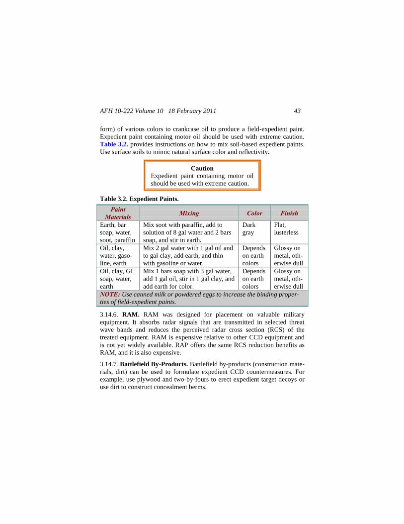
AFH 10-222 Volume 10 18 February 2011 43
form) of various colors to crankcase oil to produce a field-expedient paint.
Expedient paint containing motor oil should be used with extreme caution.
Table 3.2. provides instructions on how to mix soil-based expedient paints.
Use surface soils to mimic natural surface color and reflectivity.
Table 3.2. Expedient Paints.
Paint Materials Mixing Color Finish
Earth, bar
soap, water,
soot, paraffin
Mix soot with paraffin, add to
solution of 8 gal water and 2 bars
soap, and stir in earth.
Dark
gray
Flat,
lusterless
Oil, clay,
water, gaso-
line, earth
Mix 2 gal water with 1 gal oil and
to gal clay, add earth, and thin
with gasoline or water.
Depends
on earth
colors
Glossy on
metal, oth-
erwise dull
Oil, clay, GI
soap, water,
earth
Mix 1 bars soap with 3 gal water,
add 1 gal oil, stir in 1 gal clay, and
add earth for color.
Depends
on earth
colors
Glossy on
metal, oth-
erwise dull
NOTE: Use canned milk or powdered eggs to increase the binding proper-
ties of field-expedient paints.
3.14.6. RAM. RAM was designed for placement on valuable military
equipment. It absorbs radar signals that are transmitted in selected threat
wave bands and reduces the perceived radar cross section (RCS) of the
treated equipment. RAM is expensive relative to other CCD equipment and
is not yet widely available. RAP offers the same RCS reduction benefits as
RAM, and it is also expensive.
3.14.7. Battlefield By-Products. Battlefield by-products (construction mate-
rials, dirt) can be used to formulate expedient CCD countermeasures. For
example, use plywood and two-by-fours to erect expedient target decoys or
use dirt to construct concealment berms.
Caution
Expedient paint containing motor oil
should be used with extreme caution.
AFH 10-222 Volume 10 18 February 2011 44
3.14.8. Decoys. Decoys are among the most effective of all CCD tools. Their
main use is to draw enemy fire away from high-value targets (HVTs). De-
coys are generally expendable, and they can be elaborate or simple. Their
design depends on several factors, such as the target to be decoyed, a unit's
tactical situation, available resources, and the time available to a unit for
CCD employment. Decoys can also be preconstructed or made from field-
expedient materials. Except for selected types, preconstructed decoys are not
widely available. Proper decoy employment serves a number of tactical pur-
poses, to include:
3.14.8.1. Increasing the survivability of key unit equipment and personnel.
3.14.8.2. Deceiving the enemy about the strength, disposition, and intentions
of friendly forces.
Replacing friendly equipment removed from the forward line of
own troops.
Drawing enemy fire, which reveals its positions.
Encouraging the enemy to expend munitions on relatively low-
value targets (decoys).
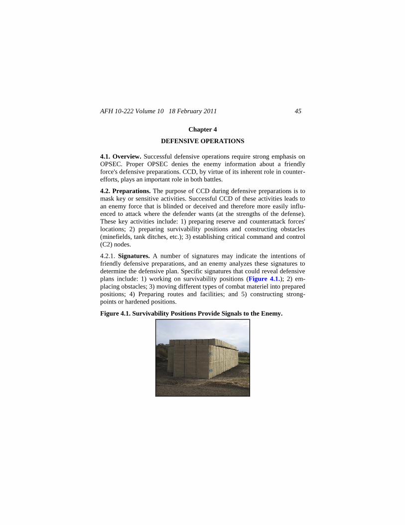
AFH 10-222 Volume 10 18 February 2011 45
Chapter 4
DEFENSIVE OPERATIONS
4.1. Overview. Successful defensive operations require strong emphasis on
OPSEC. Proper OPSEC denies the enemy information about a friendly
force's defensive preparations. CCD, by virtue of its inherent role in counter-
efforts, plays an important role in both battles.
4.2. Preparations. The purpose of CCD during defensive preparations is to
mask key or sensitive activities. Successful CCD of these activities leads to
an enemy force that is blinded or deceived and therefore more easily influ-
enced to attack where the defender wants (at the strengths of the defense).
These key activities include: 1) preparing reserve and counterattack forces'
locations; 2) preparing survivability positions and constructing obstacles
(minefields, tank ditches, etc.); 3) establishing critical command and control
(C2) nodes.
4.2.1. Signatures. A number of signatures may indicate the intentions of
friendly defensive preparations, and an enemy analyzes these signatures to
determine the defensive plan. Specific signatures that could reveal defensive
plans include: 1) working on survivability positions (Figure 4.1.); 2) em-
placing obstacles; 3) moving different types of combat materiel into prepared
positions; 4) Preparing routes and facilities; and 5) constructing strong-
points or hardened positions.
Figure 4.1. Survivability Positions Provide Signals to the Enemy.
AFH 10-222 Volume 10 18 February 2011 46
4.2.1.1. Planning. Proper planning is essential to avoid threat detection and
prevent successful enemy analysis of the engineer efforts that are integral to
defensive preparations. Engineer equipment creates significant signatures, so
minimize its use to a level that is commensurate with available time and
manpower. Disperse engineer equipment that is not required at the job site.
Complete as much work as possible without using heavy equipment, and
allow heavy equipment on site only when necessary. Engineers should mi-
nimize their time on site by conducting thorough, extensive planning and
preparation. Additional signatures include:
4.2.1.1.1. Supplies, personnel, and vehicles arriving to and departing from
the unit area.
4.2.1.1.2. Survivability positions being constructed.
4.2.1.1.3. Smoke and heat emitting from kitchens, fires, or stoves.
4.2.1.1.4. Communications facilities being operated.
4.2.1.1.5. Educational and training exercises being conducted.
4.2.1.2. Movement. Move along preplanned, concealed routes. Move and
occupy selected locations at night or during other conditions of limited visi-
bility. Practice light, noise, and track discipline to the greatest extent possi-
ble. Develop a traffic flow plan that minimizes vehicle and troop movement
to and from the unit area.
4.2.1.3. Placement and Dispersal. Site selection is crucial when concealing
engineer effort. Proper placement and dispersal of equipment and operations
are essential (Chapter 8 discusses dispersal in greater detail).
4.2.1.3.1. Use natural screens (terrain masking). When using forests as natu-
ral screens carefully consider factors such as the height and density of vege-
tation, the amount and darkness of shadows cast by the screen, and the ap-
propriateness of the particular screen for the season. The condition and quali-
ty of natural screens have a decisive effect on the capability to conceal units.
Commanders should evaluate natural screens during engineer recon missions
and conduct the missions on a timely, extensive basis.
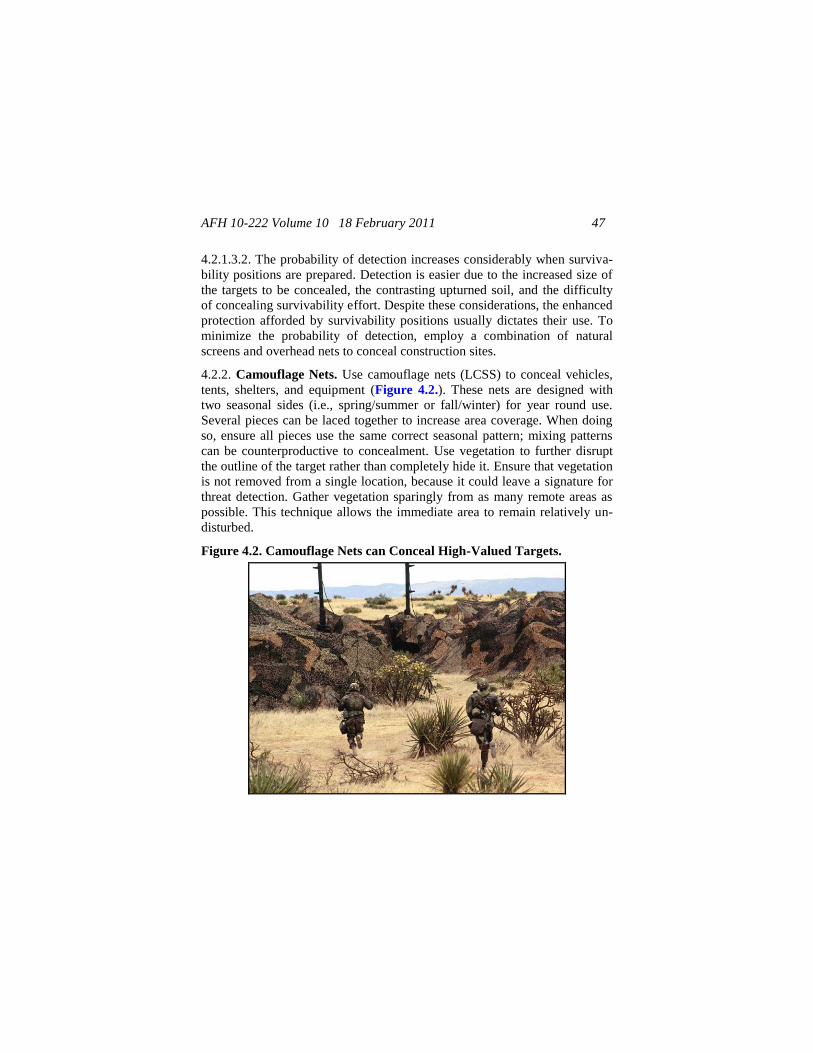
AFH 10-222 Volume 10 18 February 2011 47
4.2.1.3.2. The probability of detection increases considerably when surviva-
bility positions are prepared. Detection is easier due to the increased size of
the targets to be concealed, the contrasting upturned soil, and the difficulty
of concealing survivability effort. Despite these considerations, the enhanced
protection afforded by survivability positions usually dictates their use. To
minimize the probability of detection, employ a combination of natural
screens and overhead nets to conceal construction sites.
4.2.2. Camouflage Nets. Use camouflage nets (LCSS) to conceal vehicles,
tents, shelters, and equipment (Figure 4.2.). These nets are designed with
two seasonal sides (i.e., spring/summer or fall/winter) for year round use.
Several pieces can be laced together to increase area coverage. When doing
so, ensure all pieces use the same correct seasonal pattern; mixing patterns
can be counterproductive to concealment. Use vegetation to further disrupt
the outline of the target rather than completely hide it. Ensure that vegetation
is not removed from a single location, because it could leave a signature for
threat detection. Gather vegetation sparingly from as many remote areas as
possible. This technique allows the immediate area to remain relatively un-
disturbed.
Figure 4.2. Camouflage Nets can Conceal High-Valued Targets.
AFH 10-222 Volume 10 18 February 2011 48
4.2.3. Stoves and Fires. Strictly control the use of stoves and fires because
they produce visual and thermal signatures detectable to threat sensors. If
fires are necessary, permit them only during daylight hours and place them
in dead ground or under dense foliage. Use nets and other expedient thermal
screens to dissipate rising heat and reduce the fire's thermal signature.
4.2.4. Communications. Monitor communications to prevent enemy intelli-
gence teams from identifying unit locations.
4.2.5. CCD Discipline. Strict CCD discipline allows the continued conceal-
ment of a unit's position. The longer a unit stays in one location, the harder it
is for it to maintain CCD discipline. Extended encampments require constant
command attention to CCD discipline. The evacuation of an area also re-
quires CCD discipline to ensure that evidence (trash, vehicle tracks) is not
left for enemy detection.
4.3. Survivability Positions and Obstacles. Survivability positions include
fighting positions, protective positions (shelters), and trench-work connec-
tions. Such positions are usually constructed of earth and logs but may also
be composed of man-made building materials such as concrete.
4.3.1. Placement. Properly occupying positions and placing obstacles are
critical CCD considerations. When possible, place obstacles and occupy po-
sitions out of the direct view of threat forces (such as a reverse-slope de-
fense), at night, or under conditions of limited visibility.
4.3.2. Backgrounds. Select backgrounds that do not silhouette positions and
obstacles or provide color contrast. Use shadows to hinder an enemy's detec-
tion efforts. If possible, place positions and obstacles under overhead cover,
trees, or bushes or in any other dark area of the terrain. This technique pre-
vents the disruption of terrain lines and hinders aerial detection. CCD efforts,
however, should not hinder the integration of obstacles with fires. When
using the terrain's natural concealment properties, avoid isolated features that
draw the enemy's attention. Do not construct positions directly on or near
other clearly defined terrain features (tree lines, hedge rows, hill crests). Off-
setting positions into tree lines or below hill crests avoids silhouetting
against the background and also counters enemy fire.
AFH 10-222 Volume 10 18 February 2011 49
4.3.3. Natural Materials. Use natural materials to supplement artificial ma-
terials. Before constructing positions and obstacles, remove and save natural
materials (turf, leaves, humus, etc.) for use in restoring the terrain's natural
appearance for deception purposes. During excavation, collect spoil in carry-
ing devices for careful disposal. When preparing survivability positions and
obstacles:
4.3.3.1. Avoid disturbing the natural look of surroundings. Use camouflage
nets and natural vegetation to further distort the outline of a position, to hide
the bottom of an open position or trench, and to mask spoil used as a parapet.
To further avoid detection, replace natural materials regularly or when they
wilt or change color.
4.3.3.2. Use natural materials to help conceal machine-gun emplacements.
Machine guns are priority targets, and concealing them is an essential com-
bat task. Although CCD is important, placement is the primary factor in con-
cealing machine guns.
4.3.3.3. Place ammunition in defilade positions. Proper placement, coupled
with the use of artificial and natural CCD materials, provides the maximum
possible concealment. Also consider removable overhead concealment.
4.3.3.4. Use decoy positions and phony obstacles to draw enemy attention
away from actual survivability positions and traces of obstacle preparation.
Decoys serve the additional function of drawing enemy fire, allowing easier
targeting of an enemy's weapons systems.
4.4. Battle. CCD during the defensive battle is essentially the same as for the
offensive battle. While a majority of the battle is normally fought from pre-
pared, concealed positions, defensive forces still maneuver to prevent enemy
breakthroughs or to counterattack. When maneuvering, units should:
4.4.1. Adapt to the terrain.
4.4.2. Make optimum use of concealed routes.
4.4.3. Preselect and improve concealed routes to provide defensive forces
with a maneuver advantage.
AFH 10-222 Volume 10 18 February 2011 50
4.4.4. Plan smoke operations to provide additional concealment for maneu-
vering forces.
AFH 10-222 Volume 10 18 February 2011 51
Chapter 5
HIGH-VALUE TARGETS
5.1. Overview. The purpose of threat doctrine is for enemy forces to locate,
target, and destroy deep targets, thereby degrading friendly capabilities while
adding offensive momentum to attacking enemy forces. Enemy commanders
focus their most sophisticated sensors in search of HVTs. By attacking these
targets, enemy forces hope to deny adequate C2, combat support, or resupply
operations to forward friendly forces throughout the battle-space. Therefore,
properly employing CCD at key fixed installations, such as command posts
(CPs) and airfields, is essential to survival on a battlefield.
5.2. Plans. No single solution exists for enhancing the survivability of HVTs
with CCD (except for large-area smoke screens). The characteristics of many
such targets are unique and require the creative application of CCD prin-
ciples and techniques. Therefore, the CCD planning process presented in this
section is not intended to impose a regimen that must be followed at all
costs. Rather, it suggests a logical sequence that has proven successful over
time. In fact, the steps outlined below often lead to creative CCD solutions
simply because they allow designers to consider the many options, benefits,
and pitfalls of CCD employment. No CCD plan is wrong if it achieves the
intended signature-management goals and does not impair mission accom-
plishment. Each commander should develop the unit's CCD plan based on
awareness, if not a comprehensive assessment, of detectable EM signatures
emitted by HVTs under his command. He or she should evaluate these signa-
tures by considering the enemy's expected RSTA capabilities (airborne and
ground-based), knowledge of the target area, and weapons-on-target capabil-
ity.
5.3. Objective. A CCD plan increases target survivability within the limits
of available resources. The design procedure must systematically determine
which features of a given target are conspicuous, why those features are con-
spicuous, and how CCD principles and techniques can best eliminate or re-
duce target signatures. CCD should decrease the effectiveness of enemy at-
tacks by interfering with its target-acquisition process, which in turn increas-
es target survivability.
AFH 10-222 Volume 10 18 February 2011 52
5.4. Planning Process. The steps outlined below provide guidance for de-
signing CCD plans for HVTs. The detailed planning approach is applicable
in any situation where CCD employment is necessary, but more so when the
plans include HVTs.
5.4.1. Step 1-Identify the Threat. Identify the principal threat sensors, wea-
pon-delivery platforms, and likely directions of attack.
5.4.2. Step 2-Identify Critical Facilities. Identify critical HVTs. Include
those that are critical from an operational standpoint and those that may pro-
vide reference points (cues) for an attack on more lucrative targets.
5.4.3. Step 3-Evaluate facilities. Once the critical HVTs are identified, fo-
cus efforts on identifying the target features that might be conspicuous to an
enemy RSTA. Consider multispectral (visual, thermal, NIR, radar) signa-
tures in this assessment. The seven recognition factors (Chapter 3) are an
excellent framework for conducting this assessment. Include a review of area
maps, site plans, photographs, and aerial images of the target area.
5.4.4. Step 4-Quantify Signatures. Quantify the multispectral signatures
that are emitted by high-value facilities. Base the quantification on actual
surveys of critical facilities, using facsimiles of threat sensors when possible.
Specify the EM wavelengths in which targets are most vulnerable, and de-
velop signature-management priorities.
5.4.5. Step 5-Establish CCD Goals. Establish specific CCD goals for
HVTs. These goals should indicate the signature reduction (or increase) de-
sired and the resources available for CCD implementation. Base these goals
on the results of steps 1 through 4. Change the CCD goals as the planning
process develops and reiterate them accordingly.
5.4.5. Step 6-Select Materials and Techniques. Select CCD materials and
techniques that best accomplish signature-management goals within logistic-
al, maintenance, and resource constraints. Expedient, off-the-shelf materials
and battlefield by-products are not identified in this publication, but they are
always optional CCD materials.
5.4.6. Step 7-Organize the Plan. Develop a CCD plan that matches goals
with available materials, time and manpower constraints, and operational
AFH 10-222 Volume 10 18 February 2011 53
considerations. If the goals are unobtainable, repeat steps 5 and 6 until a ma-
nageable plan is developed.
5.4.7. Step 8-Execute the Plan. Once a feasible CCD plan is developed,
execute it. Store temporary or expedient materials inconspicuously. Conduct
deployment training on a schedule that denies enemy intelligence teams the
opportunity to identify the countermeasures or develop methods to defeat the
CCD.
5.4.8. Step 9-Evaluate the CCD. The final step in the CCD planning
process is to evaluate the deployed CCD materials and techniques. Important
questions to ask in this evaluation include the following:
5.4.8.1. Does CCD increase the survivability of HVTs?
5.4.8.2. Does deployed CCD meet the signature-management goals outlined
in the plan?
5.4.8.3. Is deployed CCD operationally compatible with the treated target(s)?
5.4.8.4. Are CCD materials and techniques maintainable within manpower
and resource constraints?
5.5. Fixed Installations. Fixed installations (bases, airfields, CPs, ware-
houses, roadways, pipelines, railways, and other lines-of-communication
[LOC] facilities) provide scarce, nearly irreplaceable functional support to
ground maneuver forces. The threat to these facilities is both ground-based
and aerial. The CCD techniques for the two attack types do not necessarily
change, but the defender must be aware of the overall implications of the
CCD plan.
5.5.1. Ground Attacks. Ground attacks against fixed installations (enemy
offensives, terrorist attacks, and enemy special-force incursions) require con-
stant operational awareness by the defenders. While most CCD techniques
are conceptually designed to defend against an aerial attack, these same
techniques can affect the target-acquisition capabilities of an enemy's ground
forces to the benefit of the defender. SCSPP, LCSS, and natural vegetation
provide CCD against a ground attack. CCD discipline (light, noise, spoil)
involves prudent operational procedures that friendly troops should observe
AFH 10-222 Volume 10 18 February 2011 54
in any tactical situation, particularly in the presence of hostile ground forces.
(See Chapter 4 for more information.)
5.5.2. Aerial Attacks. Fixed installations are susceptible to aerial attacks
because of their long residence time and immobility. However, fighter-
bomber and helicopter aircrews face unique target-acquisition problems due
to the relatively short time available to locate, identify, and lock onto targets.
Fighter-bombers typically travel at high speeds, even during weapons deli-
very. This means attacking aircrews have limited search time once they
reach the target area. Helicopters travel at slower speeds but generally en-
counter similar time-on-target limitations. Because of lower flying altitudes
and slower speeds, helicopters are more vulnerable to ground defenses. In
either case, proper CCD can increase target search time making the aircraft
more vulnerable to counterattack.
5.5.3. Enemy Intelligence. The location and configuration of most fixed
installations are usually well known. CCD techniques that protect against
sophisticated surveillance sensor systems, particularly satellite-based sys-
tems, can be costly in terms of manpower, materials, and time. Steps can be
taken to reduce an enemy's detection of relocatable targets. Fixed installa-
tions are difficult to conceal from RSTA sensors due to the relatively long
residence time of fixed installations versus relocatable targets. Unless the
construction process for a given fixed installation was conducted secretly,
defenders can safely assume that enemy RSTA sensors have previously de-
tected and catalogued its location. Defenders can further assume that attack-
ing forces have intelligence data leading them to the general area of the fixed
installation. CCD design efforts, therefore, should focus on the multispectral
defeat or impairment of the enemy's local target-acquisition process.
5.5.4. CCD Techniques. Selected CCD techniques should capitalize on ter-
rain features that are favorable to the defender and on the short time availa-
ble to attacking aircrews for target acquisition. Use artificial and natural
means to camouflage the installation. Where time and resources allow, dep-
loy alternative targets (decoys) to draw the attention of the attacking aircrews
away from the fixed installation. Comprehensive CCD designs and tech-
niques for fixed installations can be costly, yet field tests have shown that
simple, expedient techniques can be effective. HVTs are usually supplied
AFH 10-222 Volume 10 18 February 2011 55
with artificial CCD materials. If they are not, Airmen increase the survivabil-
ity of an installation by using CCD principles.
5.5.5. Other Considerations. While standard CCD materials are designed to
enhance fixed-installation survivability, they have practical limitations that
are not easily overcome. Materials applied directly to a fixed installation
may achieve the signature-management goals stated in the CCD plan. How-
ever, if other features of the target scene are not treated accordingly, the tar-
get may be well hidden but remain completely vulnerable.
5.5.5.1. For example, three weapons-storage-area (WSA) igloos are in a row.
The middle igloo is treated with CCD materials while the other two are not.
The middle igloo will still be vulnerable. The enemy knows that three igloos
exist and will probably locate the middle one no matter how well the CCD
plan is designed. However, if all three igloos are treated with CCD materials
and three decoy igloos are placed away from them, the treated igloos' survi-
vability will increase.
5.5.5.2. Furthermore, if a man-made object (traffic surface) or a natural fea-
ture (tree line) is close to the igloos, attacking forces will use these cues to
proceed to the target area even if all three igloos are treated with CCD mate-
rials. Remember, an HVT is part of an overall target scene and an attacker
must interpret the scene. Do not make his task easy. CCD plans that treat
only the target and ignore other cues (man-made or natural) within the target
scene are insufficient.
5.5.6. Command Posts (UCC). C2 systems provide military leaders with the
capability to make timely decisions, communicate the decisions to subordi-
nate units, and monitor the execution of the decisions. CPs contain vital C2
systems.
5.5.6.1. Signatures. Since World War II, the size and complexity of CPs
have increased dramatically. Their signatures have correspondingly in-
creased from a physical and communications perspective (more types of an-
tennas and transmission modes at a wider range of frequencies). As a result,
the enemy can use several conspicuous signatures to detect and target CPs
for attack. Therefore, CPs require excellent CCD to survive on the battle-
field.
AFH 10-222 Volume 10 18 February 2011 56
5.5.6.1.1. LOCs. CPs are usually located near converging LOC, such as road
or rail junctions, and often require new access and egress routes. Consider
the following regarding CCD and CPs:
5.5.6.1.1.1. Vehicle traffic. When evaluating EM signatures that CPs emit,
consider concentrations of vehicles, signs of heavy traffic (characteristic
wear and track marks), and air traffic. Park vehicles and aircraft a significant
distance from CPs.
5.5.6.1.1.2. Antennas. Antennas and their electronic emissions and numer-
ous support towers are common to most CPs. Paint antennas and support
equipment with nonconductive green, black, or brown paint if the surfaces
are shiny. If tactically feasible, use remote antennas to reduce the vulnera-
bility of the radio system to collateral damage.
5.5.6.1.1.3. Security Emplacements. Security measures (barbwire, barriers,
security and dismount points, and other types of emplacements) can indicate
CP operations. Barbwire exhibits a measurable RCS at radar frequencies.
Ensure that barbwire and concertina wire follow natural terrain lines and are
concealed as much as possible.
5.5.6.1.2. Equipment. Power generators and other heat sources produce sig-
natures that an enemy's surveillance and target-acquisition sensors can
detect. Place heat-producing equipment and other thermal sources in defilade
positions, within structures, or under natural cover. Heat diffusers, which
tone down and vent vehicle exhaust away from threat direction, are an expe-
dient means of thermal-signature reduction.
5.5.6.1.3. Defensive Positions. Defensive positions (berms, revetments,
fighting positions) for protection against direct- and indirect-fire attackers
typically create scarred earth signatures and detectable patterns due to earth
excavation.
5.5.6.2. CCD. CCD improves OPSEC and increases survivability by mini-
mizing the observable size and EM signatures of CPs. CP CCD requires re-
con, planning, discipline, security, and maintenance. Carefully controlled
traffic plans decrease the possibility of disturbing natural cover and creating
new, observable paths. Decoys are a highly effective means of confusing the

AFH 10-222 Volume 10 18 February 2011 57
enemy's target-acquisition process, particularly against airborne sensors.
Against ground threats, the same general rules of CCD discipline apply;
however, recon and heightened security patrols enhance CCD efforts against
ground attack.
5.5.6.3. Sites. CP sites, which could move every 24 hours, are still occupied
for a longer period than assembly areas. CP site selection is crucial, therefore
units should:
5.5.6.3.1. Consider the needs of supporting an extended occupation while
minimizing changes to natural terrain patterns. When constructing defensive
positions, minimize earth scarring as much as possible. If scarred earth is
unavoidable, cut vegetation, toned-down agents (paint), and camouflage nets
help conceal scarred areas.
5.5.6.3.2. Use existing LOC (roads, trails, streams, etc.). If a site requires
construction of roads or paths, make maximum use of natural concealment
and existing terrain. The fewer new lines required, the better the CP blends,
leaving natural features relatively unchanged.
5.5.6.3.3. Never locate a CP at a road junction. Road junctions are high-
priority targets for enemy forces and are easily detectable.
5.5.6.3.4. Locate a CP in an existing civilian structure, if possible, which
simplifies hiding military activity; however, ensure the structure falls within
the Laws of Armed Conflict. Choose a structure in an area where a sufficient
number of buildings with similar EM signatures can mask its location.
5.5.6.4. Telecommunications Procedures. By strictly complying with prop-
er radio, telephone, and digital communications procedures, the opportuni-
ties for an enemy to detect friendly telecommunications activities are mini-
mized. Consider the following:
5.5.6.4.1. Place antennas in locations using natural supports when possible
(trees for dipoles). As a rule of thumb, place antennas a minimum of one
wavelength away from surrounding structures or other antennas. NOTE:
One wavelength is 40 meters (typically) for low frequencies and 1 meter for
very high frequencies (VHFs).
AFH 10-222 Volume 10 18 February 2011 58
5.5.6.4.2. Move antennas as often as possible within operational constraints.
5.5.6.4.3. Use directional antennas when possible. If using non-directional
antennas, employ proper terrain-masking techniques to defeat the threat's
radio direction-finding efforts.
5.5.6.4.4. Use existing telephone lines as much as possible. Newly laid wire
is a readily observable signature that can reveal a CP's location. Communica-
tions wire and cable should follow natural terrain lines and be concealed in
the best way possible.
5.5.6.5. CCD Discipline. Maintain CCD discipline after occupying a site.
Establish and use designated foot paths to, from, and within a CP's area. If a
unit occupies a site for more than 24 hours, consider periodically rerouting
foot paths to avoid detectable patterns. Conceal security and dismount points
and other individual emplacements, and make paths to the CP inconspicuous.
Enforce proper disposal procedures for trash and spoil. Rigidly enforce light
and noise discipline. Enhance the realism of a decoy CP by making it appear
operational. Allow CCD discipline to be lax in the decoy CP, thus making it
a more conspicuous target than the genuine CP.
5.5.7. Supply and Water Points. Supply and water points provide logistical
support—the backbone of sustained combat operations. As these targets are
relatively immobile and the object of an enemy's most sophisticated sensors,
using CCD is one of the most effective means to improve their survivability.
5.5.7.1. Operations. Many CCD methods associated with assembly areas
and CPs also apply to supply and water points, but with additional require-
ments. Large amounts of equipment and supplies are quickly brought into
tactical areas and delivered to supply points located as close to personnel as
possible. Supplies must be unloaded and concealed quickly, while supply
points remain open and accessible for distribution. Under these conditions,
multiple supply points are generally easier to camouflage than single, large
ones. Decoy supply and water points can also confuse a threat's targeting
efforts.
5.5.7.2. CCD. Take maximum advantage of natural cover and concealment.
Configure logistics layouts to conform to the local ground pattern. Creativity
AFH 10-222 Volume 10 18 February 2011 59
can play a role in this effort. The following guidance enhances concealment
of these operations:
5.5.7.2.1. Avoid establishing regular (square or rectangular) perimeter
shapes for an area.
5.5.7.2.2. Select locations where concealed access and egress routes are al-
ready established and easily controlled.
5.5.7.2.3. Use roads with existing overhead concealment if you need new
access roads. Conceal access over short, open areas with overhead nets.
5.5.7.2.4. Control movement into and out of the supply area.
5.5.7.2.5. Mix and disperse supply-point stocks to the maximum extent poss-
ible. This not only avoids a pattern of stockpile shapes but also avoids easy
destruction of one entire commodity.
5.5.7.2.6. Space stocks irregularly (in length and depth) to avoid recogniza-
ble patterns. Stack supplies as low as possible to avoid shadows. Dig sup-
plies in if resources allow. In digging operations, disperse the spoil so as not
to produce large piles of earth.
5.5.7.2.7. Cover stocks with nets and other materials that blend with back-
ground patterns and signatures. Flattops (large, horizontal CCD nets) are
effective for concealing supply-point activities when resources allow their
construction and when supply points are not too large. Dunnage from supply
points provides excellent material for expedient decoys.
5.5.7.3. Traffic Control. Ensure that vehicles cause minimal changes to the
natural terrain as a result of movement into, within, and out of the area. Pro-
vide concealment and control of vehicles waiting to draw supplies. Rigidly
practice and enforce CCD discipline and OPSEC. Debris control could be a
problem and requires constant attention.
5.5.7.4. Water Points. CCD for water points includes the following addi-
tional considerations:
5.5.7.4.1. Spillage. Water spillage can have positive and negative effects on
a unit's CCD posture. Standing pools of water reflect light that is visible to
AFH 10-222 Volume 10 18 February 2011 60
observers. Pools can also scatter radar waves, resulting in conspicuous black-
hole returns on radar screens. Therefore, minimize water spillage and pro-
vide adequate drainage for runoff. On the other hand, dispersed water can be
used to reduce the thermal signatures of large, horizontal surfaces. However,
use this technique sparingly and in such a way that pools do not form.
5.5.7.4.2. Equipment. Use adequate natural and artificial concealment for
personnel, storage tanks, and specialized pumping and purification equip-
ment. Conceal water-point equipment to eliminate shine from damp surfaces.
Conceal shine by placing canvas covers on bladders, using camouflage nets,
and placing foliage on and around bladders. This also distorts the normal
shape of the bladders.
5.5.7.4.3. Scheduling. Enhance CCD discipline at water points by establish-
ing and strictly enforcing a supply schedule for units. The lack of or viola-
tion of a supply schedule produces a concentration of waiting vehicles that is
difficult to conceal.
5.5.8. Airfields. Airfields are among the most important of all battlefield
HVTs. CE is responsible for a number of airfield assets and should consider
CCD measures to protect them.
5.5.8.1. Aircraft Arresting Systems (AASs). Consider camouflaging AASs
to prevent direct targeting.
5.5.8.2. Emergency Airfield Lighting Systems (EALS). Camouflage EALS
generators and regulators to enhance survivability.
5.5.8.3. Defensive Positions. Constructing defensive positions can create
detectable areas of scarred earth. Minimize disturbances to the surrounding
area when constructing defensive positions. Cover scarred earth with cut
vegetation, camouflage nets, or toned-down agents.
5.5.8.4. Vehicles. Large vehicles can be effectively concealed with camouf-
lage nets. Also, properly placing these vehicles to use terrain features and
indigenous vegetation increases their survivability. Expedient vehicle decoys
provide an enemy with alternate targets, and proper CCD discipline is essen-
tial.
AFH 10-222 Volume 10 18 February 2011 61
5.5.8.5. In addition, airfields are typically comprised of several parts that
make up the whole, including parking aprons, aircraft maintenance areas,
and arming and refueling points. While CE may not be responsible for these
parts, the Wing may request CE’s help in protecting these assets.
5.5.8.5.1. Parking Aprons. Aircraft are highly conspicuous targets because
of their awkward shape, distinctive thermal signatures, and large RCS. An
enemy expends a lot of time and energy attempting to locate aircraft when
they are most vulnerable, parked on the ground. Once it finds them, the ene-
my aggressively directs offensive operations against them.
5.5.8.5.2. Aircraft Maintenance Areas. The most conspicuous features of
aircraft maintenance areas are the hangers or large transportable maintenance
shelters. These shelters are highly visible and indicate the presence of air-
craft to an enemy. Maintenance areas occupy large areas to allow for ground
handling of aircraft. Traffic patterns around maintenance areas are also
strong visual cues to the enemy. Maintenance assets, including aviation
shops, have characteristically distinct multispectral cues.
5.5.8.5.3. Arming and Refueling Points. Arming and refueling points pro-
vide POL and ammunition support to airfields and other base units. Arming
and refueling points consists of fuel bladders, large vehicles, fueling appara-
tus, and bulk ammunition. Due to safety requirements, arming and refueling
points are dispersed as much as possible within terrain and operational con-
straints. Each element is detectable with multispectral radar. In a forward
arming and refueling point (FARP):
5.5.8.5.3.1. Fuel bladders contain petroleum liquids whose thermal mass is a
strong IR cue relative to the background. Bladders are usually bermed,
which means that visible earth scarring is necessary to construct the berm.
5.5.8.5.3.2. Large vehicles are conspicuous in all wavelengths.
5.5.8.5.3.3. Fueling areas are generally arranged in such a way that the fuel-
ing apparatus (hoses, pumps) are arranged linearly in an open area for safe
and easy access. The linear deployment of these hoses is a strong visual cue,
and their dark color usually contrasts with the background. The dark hoses
AFH 10-222 Volume 10 18 February 2011 62
experience solar loading and the petroleum, oils, and lubricants (POL) within
the hoses can provide a thermal cue.
5.5.8.5.4. Equipment. Palletized ammunition and support equipment ac-
company airfields. Such equipment is often stacked in regular, detectable
patterns.
5.5.8.5.5. Aircraft. Aircraft create large dust plumes when deployed to un-
paved or dusty areas. Such plumes are distinct visual cues and indicate the
presence of aircraft to an enemy. To avoid dust, park aircraft next to grassy
areas or where the earth is hard-packed. If such areas are unavailable, dis-
perse water on the area to minimize dust plumes. However, water-soaked
earth can also be an IR detection cue so use this option sparingly and, if
possible, at night. Several chemical dust palliatives are available that provide
excellent dust control for aviation areas.
5.5.8.5.5.1. Parked Aircraft. Camouflage nets, berms, stacked equipment,
and revetments can effectively conceal parked aircraft. Vertical screens con-
structed from camouflage nets help conceal parked aircraft, particularly
against ground-based threats. However, CCD techniques for rapid-response
aircraft must not impair operational requirements, meaning that obtrusive,
permanent CCD techniques are generally not an option. Also, foreign object
damage (FOD) is a critical concern for all aviation assets. CCD for parked
aircraft depends on the expected ground time between flights. The com-
mander must approve all aircraft CCD techniques before implementation.
5.5.8.5.5.2. Aircraft Refueling. Aircraft refueling positions, particularly fuel
hoses, should be dispersed and arrayed in a nonlinear configuration. The
hoses can be concealed at periodic locations with cut vegetation or a light
earth/sod covering to reduce visual and thermal signatures.
5.5.8.5.6. Dunnage. Quickly conceal all dunnage and packing materials to
minimize the evidence of airfield use.
AFH 10-222 Volume 10 18 February 2011 63
Chapter 6
SPECIAL ENVIRONMENTS
6.1. Overview. The fundamentals of CCD do not change between environ-
ments. The seven rules for avoiding detection and the seven recognition fac-
tors that are listed in Chapter 3 and the three CCD principles—preventing
detection, improving survivability, and improving deception capabilities—
still apply. However, the guidelines for their application change. Different
environments require thoughtful, creative, and unique CCD techniques. This
chapter discusses different CCD techniques that have proven effective in
three special environments—desert, snow-covered areas, and urban terrain.
6.2. Desert. The color of desert terrain varies from pink to blue, depending
on the minerals in the soil and the time of the day. No color or combination
of colors matches all deserts. Patches of uniform color in the desert are
usually 10 times larger than those in wooded areas. These conditions have
led to the development of a neutral, monotone tan as the best desert CCD
paint color.
6.2.1. Topography. Although desert terrain may appear featureless, it is not
completely flat. In some ways, desert terrain resembles unplowed fields;
barren, rocky areas; grasslands; and steppes.
6.2.2. Shadows. The closer a target is to the ground, the smaller its shadow;
and a small shadow is easier to conceal from aerial observation. The proper
draping of CCD nets will alter or disrupt the regular, sharp-edged shadows
of military targets and allow target shadows to appear more like natural sha-
dows. When supplemented by artificial materials, natural shadows cast by
folds of the ground can be used for CCD purposes. The best solution to the
shadow problem in desert terrain is to dig in and use overhead concealment
or cover. Otherwise, park vehicles in a way that minimizes their broadside
exposure to the sun.
6.2.3. Placement. Proper placement and shadow disruption remain effective
techniques. Take advantage of terrain masking by placing assets in gullies,
washes, wadis (dry streambeds), and ravines; this reduces their shadows and
silhouettes (be sure to get weather forecasts before placing assets in areas
AFH 10-222 Volume 10 18 February 2011 64
subject to flooding). More dispersion is necessary in desert terrain than in
wooded areas. Move assets as the sun changes position to keep equipment in
shadows.
6.2.4. Terrain Mottling. Use terrain mottling (mark with spots or blotches
of a different color or shade) when the ground offers little opportunity for
concealment. This technique involves scarring the earth with bulldozers,
which creates darker areas on which to place equipment for better blending
with the background. Ensure that the mottled areas are irregularly shaped
and at least twice the size of the target you are concealing. Place the target
off center in the mottled area and drape it with camouflage nets. When em-
ploying the scarring technique, dig two to three times as many scars as piec-
es of equipment being concealed. Doing this prevents the mere presence of
mottled areas from giving away a unit's location.
6.2.5. Movement Discipline. Movement discipline is especially important in
the desert. Desert terrain is uniform and fragile, making it easily disturbed by
vehicle tracks. Vehicle movement also produces dust and diesel plumes that
are easily detectable in the desert. When movement is necessary, move along
the shortest route and on the hardest ground. Shine is a particularly acute
desert problem due to the long, uninterrupted hours of sunlight. To deal with
this problem, remove all reflective surfaces or cover them with burlap. Use
matte CCD paint or expedient paints (see Table 3.2.) to dull the gloss of a
vehicle's finish. Shade optical devices (binoculars, gun sights) when using
them.
6.2.6. Noise and Light Discipline. Noise and light discipline is particularly
important in desert terrain since sound and light can be detected at greater
distances on clear desert nights. The techniques for reducing these signatures
remain the same as for other environments. Be aware that thermal sensors,
while not as effective during the day, have an ideal operating environment
during cold desert nights. Starting all vehicle and equipment engines simul-
taneously is a technique that can be used to confuse enemy acoustical sur-
veillance efforts.
6.3. Snow-Covered Areas. When the main background is white, apply white
paint or whitewash over the permanent CCD paint pattern. The amount of
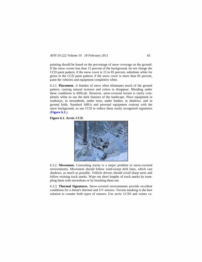
AFH 10-222 Volume 10 18 February 2011 65
painting should be based on the percentage of snow coverage on the ground:
If the snow covers less than 15 percent of the background, do not change the
CCD paint pattern; if the snow cover is 15 to 85 percent, substitute white for
green in the CCD paint pattern; if the snow cover is more than 85 percent,
paint the vehicles and equipment completely white.
6.3.1. Placement. A blanket of snow often eliminates much of the ground
pattern, causing natural textures and colors to disappear. Blending under
these conditions is difficult. However, snow-covered terrain is rarely com-
pletely white so use the dark features of the landscape. Place equipment in
roadways, in streambeds, under trees, under bushes, in shadows, and in
ground folds. Standard ABUs and personal equipment contrast with the
snow background, so use CCD to reduce these easily recognized signatures
(Figure 6.1.).
Figure 6.1. Arctic CCD.
6.3.2. Movement. Concealing tracks is a major problem in snow-covered
environments. Movement should follow wind-swept drift lines, which cast
shadows, as much as possible. Vehicle drivers should avoid sharp turns and
follow existing track marks. Wipe out short lengths of track marks by tram-
pling them with snowshoes or by brushing them out.
6.3.3. Thermal Signatures. Snow-covered environments provide excellent
conditions for a threat's thermal and UV sensors. Terrain masking is the best
solution to counter both types of sensors. Use arctic LCSS and winter ca-
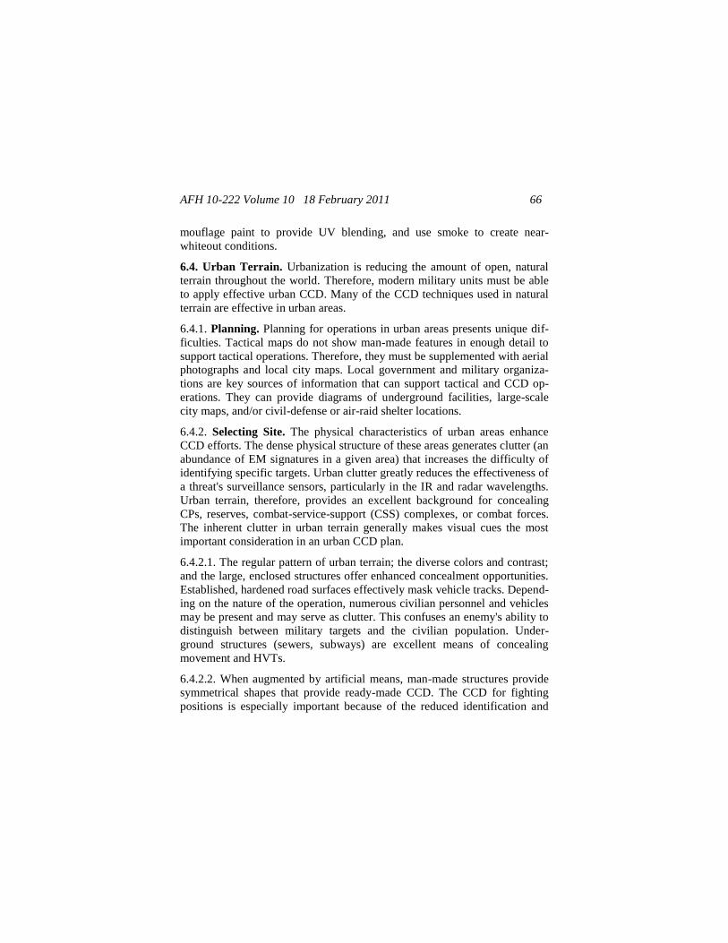
AFH 10-222 Volume 10 18 February 2011 66
mouflage paint to provide UV blending, and use smoke to create near-
whiteout conditions.
6.4. Urban Terrain. Urbanization is reducing the amount of open, natural
terrain throughout the world. Therefore, modern military units must be able
to apply effective urban CCD. Many of the CCD techniques used in natural
terrain are effective in urban areas.
6.4.1. Planning. Planning for operations in urban areas presents unique dif-
ficulties. Tactical maps do not show man-made features in enough detail to
support tactical operations. Therefore, they must be supplemented with aerial
photographs and local city maps. Local government and military organiza-
tions are key sources of information that can support tactical and CCD op-
erations. They can provide diagrams of underground facilities, large-scale
city maps, and/or civil-defense or air-raid shelter locations.
6.4.2. Selecting Site. The physical characteristics of urban areas enhance
CCD efforts. The dense physical structure of these areas generates clutter (an
abundance of EM signatures in a given area) that increases the difficulty of
identifying specific targets. Urban clutter greatly reduces the effectiveness of
a threat's surveillance sensors, particularly in the IR and radar wavelengths.
Urban terrain, therefore, provides an excellent background for concealing
CPs, reserves, combat-service-support (CSS) complexes, or combat forces.
The inherent clutter in urban terrain generally makes visual cues the most
important consideration in an urban CCD plan.
6.4.2.1. The regular pattern of urban terrain; the diverse colors and contrast;
and the large, enclosed structures offer enhanced concealment opportunities.
Established, hardened road surfaces effectively mask vehicle tracks. Depend-
ing on the nature of the operation, numerous civilian personnel and vehicles
may be present and may serve as clutter. This confuses an enemy's ability to
distinguish between military targets and the civilian population. Under-
ground structures (sewers, subways) are excellent means of concealing
movement and HVTs.
6.4.2.2. When augmented by artificial means, man-made structures provide
symmetrical shapes that provide ready-made CCD. The CCD for fighting
positions is especially important because of the reduced identification and
AFH 10-222 Volume 10 18 February 2011 67
engagement ranges (100 meters or less) typical of urban fighting. Limit or
conceal movement and shine. These signatures provide the best opportunity
for successful threat surveillance in urban terrain. Careful placement of
equipment and fighting positions remains important to provide visual CCD
and avoid detection by contrast (thermal sensors detecting personnel and
equipment silhouetted against colder buildings or other large, flat surfaces).
6.4.3. Establishing Fighting Positions. The fundamental CCD rule is to
maintain the natural look of an area as much as possible. Buildings with
large, thick walls and few narrow windows provide the best concealment.
When selecting a position inside a building, Airmen should:
6.4.3.1. Avoid lighted areas around windows.
6.4.3.2. Stand in shadows when observing or firing weapons through win-
dows.
6.4.3.3. Select positions with covered and concealed access and egress routes
(breaches in buildings, underground systems, trenches).
6.4.3.4. Develop decoy positions to enhance CCD operations.
6.4.4. Placing Vehicles. Hide vehicles in large structures, if possible, and
use local materials to help blend vehicles with the background environment.
Paint vehicles and equipment a solid, dull, dark color. If you cannot do this,
use expedient paints to subdue the lighter, sand-colored portions of the
SCSPP. When placing vehicles outdoors, use shadows for concealment.
Move vehicles during limited visibility or screen them with smoke.
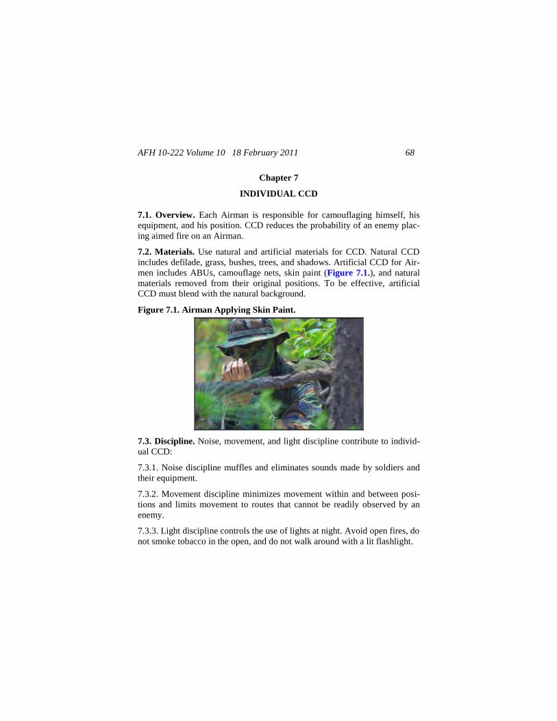
AFH 10-222 Volume 10 18 February 2011 68
Chapter 7
INDIVIDUAL CCD
7.1. Overview. Each Airman is responsible for camouflaging himself, his
equipment, and his position. CCD reduces the probability of an enemy plac-
ing aimed fire on an Airman.
7.2. Materials. Use natural and artificial materials for CCD. Natural CCD
includes defilade, grass, bushes, trees, and shadows. Artificial CCD for Air-
men includes ABUs, camouflage nets, skin paint (Figure 7.1.), and natural
materials removed from their original positions. To be effective, artificial
CCD must blend with the natural background.
Figure 7.1. Airman Applying Skin Paint.
7.3. Discipline. Noise, movement, and light discipline contribute to individ-
ual CCD:
7.3.1. Noise discipline muffles and eliminates sounds made by soldiers and
their equipment.
7.3.2. Movement discipline minimizes movement within and between posi-
tions and limits movement to routes that cannot be readily observed by an
enemy.
7.3.3. Light discipline controls the use of lights at night. Avoid open fires, do
not smoke tobacco in the open, and do not walk around with a lit flashlight.
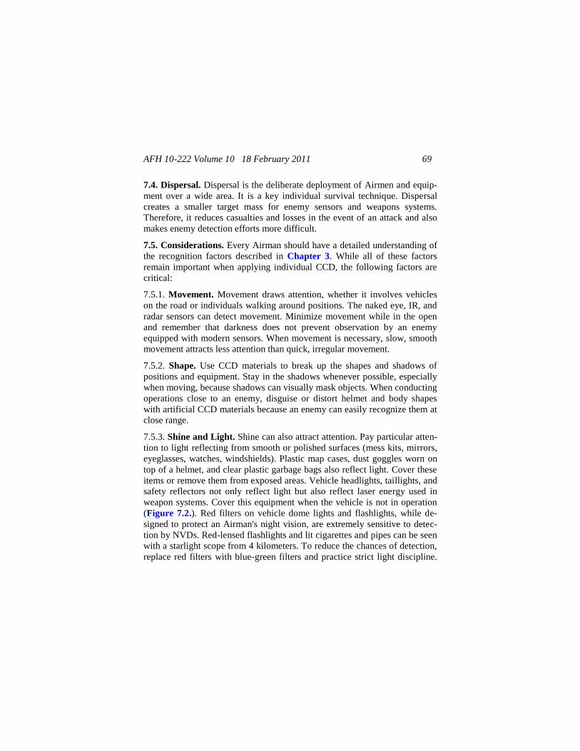
AFH 10-222 Volume 10 18 February 2011 69
7.4. Dispersal. Dispersal is the deliberate deployment of Airmen and equip-
ment over a wide area. It is a key individual survival technique. Dispersal
creates a smaller target mass for enemy sensors and weapons systems.
Therefore, it reduces casualties and losses in the event of an attack and also
makes enemy detection efforts more difficult.
7.5. Considerations. Every Airman should have a detailed understanding of
the recognition factors described in Chapter 3. While all of these factors
remain important when applying individual CCD, the following factors are
critical:
7.5.1. Movement. Movement draws attention, whether it involves vehicles
on the road or individuals walking around positions. The naked eye, IR, and
radar sensors can detect movement. Minimize movement while in the open
and remember that darkness does not prevent observation by an enemy
equipped with modern sensors. When movement is necessary, slow, smooth
movement attracts less attention than quick, irregular movement.
7.5.2. Shape. Use CCD materials to break up the shapes and shadows of
positions and equipment. Stay in the shadows whenever possible, especially
when moving, because shadows can visually mask objects. When conducting
operations close to an enemy, disguise or distort helmet and body shapes
with artificial CCD materials because an enemy can easily recognize them at
close range.
7.5.3. Shine and Light. Shine can also attract attention. Pay particular atten-
tion to light reflecting from smooth or polished surfaces (mess kits, mirrors,
eyeglasses, watches, windshields). Plastic map cases, dust goggles worn on
top of a helmet, and clear plastic garbage bags also reflect light. Cover these
items or remove them from exposed areas. Vehicle headlights, taillights, and
safety reflectors not only reflect light but also reflect laser energy used in
weapon systems. Cover this equipment when the vehicle is not in operation
(Figure 7.2.). Red filters on vehicle dome lights and flashlights, while de-
signed to protect an Airman's night vision, are extremely sensitive to detec-
tion by NVDs. Red-lensed flashlights and lit cigarettes and pipes can be seen
with a starlight scope from 4 kilometers. To reduce the chances of detection,
replace red filters with blue-green filters and practice strict light discipline.
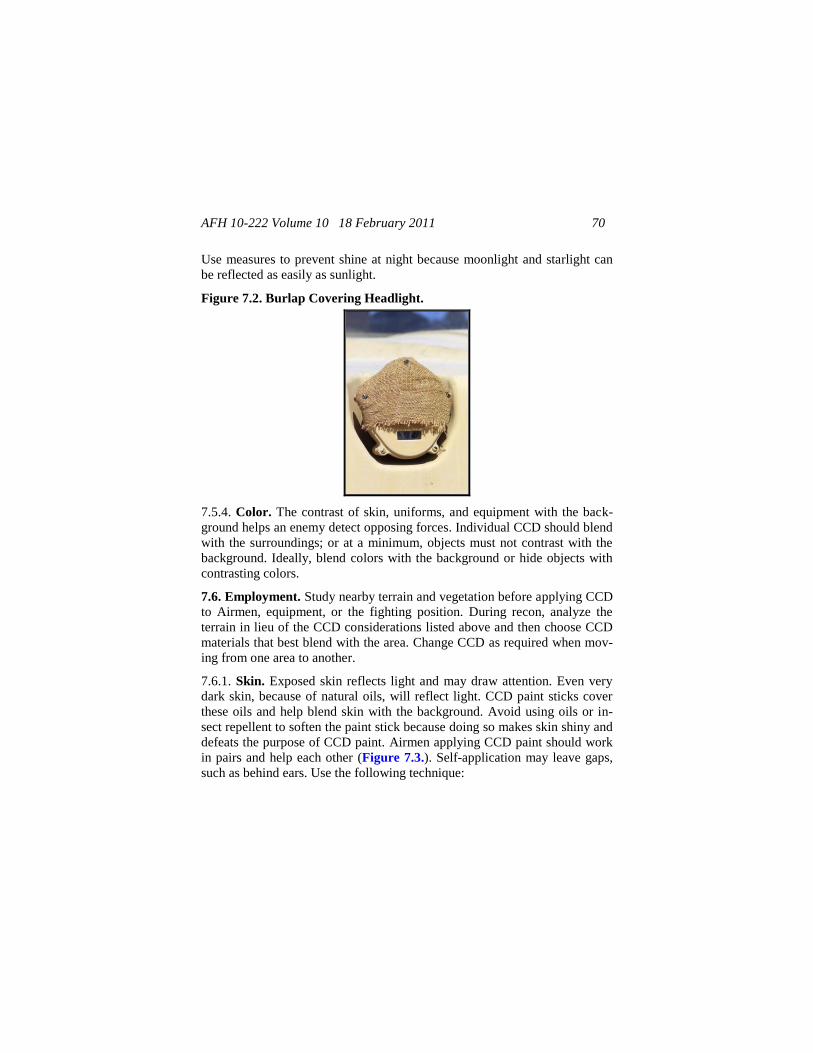
AFH 10-222 Volume 10 18 February 2011 70
Use measures to prevent shine at night because moonlight and starlight can
be reflected as easily as sunlight.
Figure 7.2. Burlap Covering Headlight.
7.5.4. Color. The contrast of skin, uniforms, and equipment with the back-
ground helps an enemy detect opposing forces. Individual CCD should blend
with the surroundings; or at a minimum, objects must not contrast with the
background. Ideally, blend colors with the background or hide objects with
contrasting colors.
7.6. Employment. Study nearby terrain and vegetation before applying CCD
to Airmen, equipment, or the fighting position. During recon, analyze the
terrain in lieu of the CCD considerations listed above and then choose CCD
materials that best blend with the area. Change CCD as required when mov-
ing from one area to another.
7.6.1. Skin. Exposed skin reflects light and may draw attention. Even very
dark skin, because of natural oils, will reflect light. CCD paint sticks cover
these oils and help blend skin with the background. Avoid using oils or in-
sect repellent to soften the paint stick because doing so makes skin shiny and
defeats the purpose of CCD paint. Airmen applying CCD paint should work
in pairs and help each other (Figure 7.3.). Self-application may leave gaps,
such as behind ears. Use the following technique:
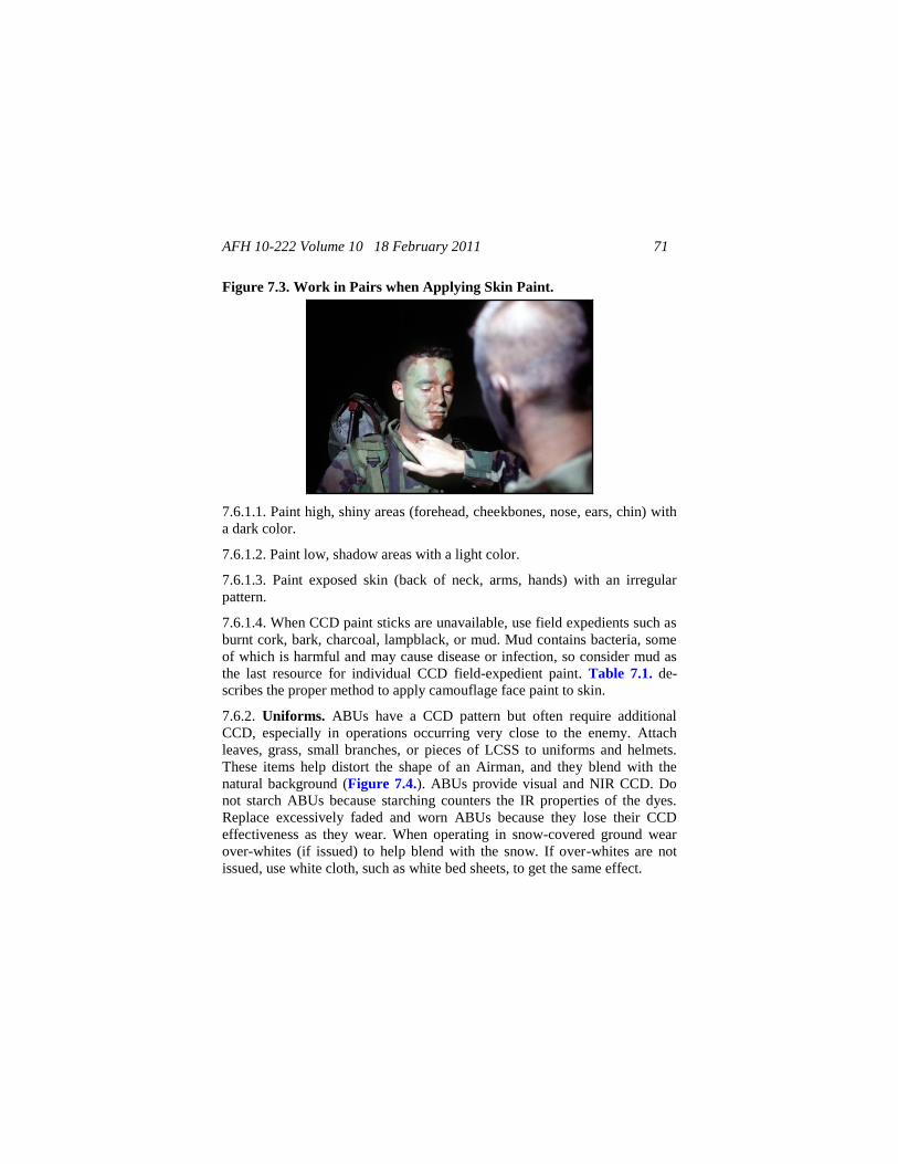
AFH 10-222 Volume 10 18 February 2011 71
Figure 7.3. Work in Pairs when Applying Skin Paint.
7.6.1.1. Paint high, shiny areas (forehead, cheekbones, nose, ears, chin) with
a dark color.
7.6.1.2. Paint low, shadow areas with a light color.
7.6.1.3. Paint exposed skin (back of neck, arms, hands) with an irregular
pattern.
7.6.1.4. When CCD paint sticks are unavailable, use field expedients such as
burnt cork, bark, charcoal, lampblack, or mud. Mud contains bacteria, some
of which is harmful and may cause disease or infection, so consider mud as
the last resource for individual CCD field-expedient paint. Table 7.1. de-
scribes the proper method to apply camouflage face paint to skin.
7.6.2. Uniforms. ABUs have a CCD pattern but often require additional
CCD, especially in operations occurring very close to the enemy. Attach
leaves, grass, small branches, or pieces of LCSS to uniforms and helmets.
These items help distort the shape of an Airman, and they blend with the
natural background (Figure 7.4.). ABUs provide visual and NIR CCD. Do
not starch ABUs because starching counters the IR properties of the dyes.
Replace excessively faded and worn ABUs because they lose their CCD
effectiveness as they wear. When operating in snow-covered ground wear
over-whites (if issued) to help blend with the snow. If over-whites are not
issued, use white cloth, such as white bed sheets, to get the same effect.
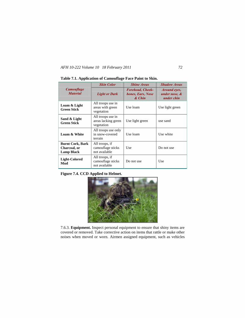
AFH 10-222 Volume 10 18 February 2011 72
Table 7.1. Application of Camouflage Face Paint to Skin.
Camouflage Material
Skin Color Shine Areas Shadow Areas
Light or Dark Forehead, Cheek-bones, Ears, Nose
& Chin
Around eyes, under nose, &
under chin
Loam & Light
Green Stick
All troops use in
areas with green vegetation
Use loam Use light green
Sand & Light
Green Stick
All troops use in
areas lacking green vegetation
Use light green use sand
Loam & White
All troops use only
in snow-covered terrain
Use loam Use white
Burnt Cork, Bark
Charcoal, or
Lamp Black
All troops, if
camouflage sticks not available
Use Do not use
Light-Colored
Mud
All troops, if
camouflage sticks
not available
Do not use Use
Figure 7.4. CCD Applied to Helmet.
7.6.3. Equipment. Inspect personal equipment to ensure that shiny items are
covered or removed. Take corrective action on items that rattle or make other
noises when moved or worn. Airmen assigned equipment, such as vehicles
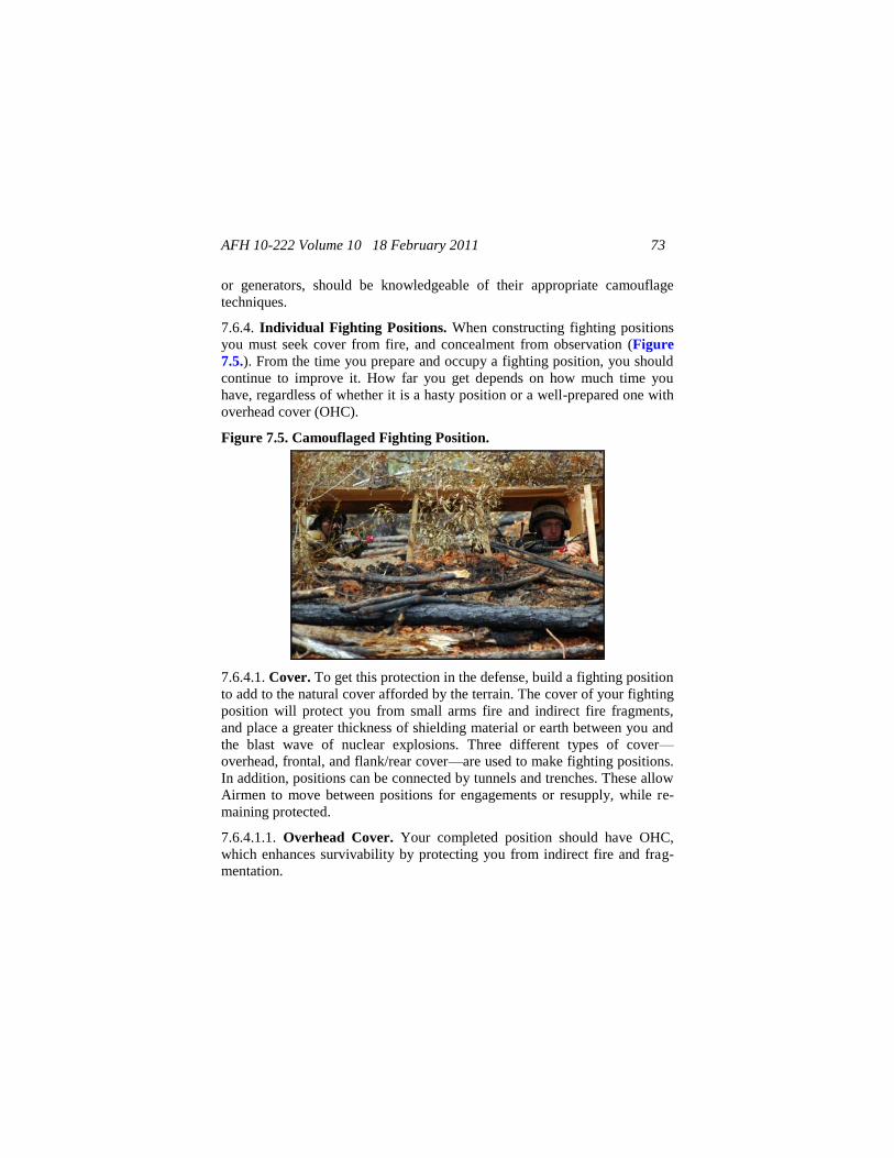
AFH 10-222 Volume 10 18 February 2011 73
or generators, should be knowledgeable of their appropriate camouflage
techniques.
7.6.4. Individual Fighting Positions. When constructing fighting positions
you must seek cover from fire, and concealment from observation (Figure
7.5.). From the time you prepare and occupy a fighting position, you should
continue to improve it. How far you get depends on how much time you
have, regardless of whether it is a hasty position or a well-prepared one with
overhead cover (OHC).
Figure 7.5. Camouflaged Fighting Position.
7.6.4.1. Cover. To get this protection in the defense, build a fighting position
to add to the natural cover afforded by the terrain. The cover of your fighting
position will protect you from small arms fire and indirect fire fragments,
and place a greater thickness of shielding material or earth between you and
the blast wave of nuclear explosions. Three different types of cover—
overhead, frontal, and flank/rear cover—are used to make fighting positions.
In addition, positions can be connected by tunnels and trenches. These allow
Airmen to move between positions for engagements or resupply, while re-
maining protected.
7.6.4.1.1. Overhead Cover. Your completed position should have OHC,
which enhances survivability by protecting you from indirect fire and frag-
mentation.
AFH 10-222 Volume 10 18 February 2011 74
7.6.4.1.2. Frontal Cover. Your position needs frontal cover to protect you
from small arms fire to the front. Frontal cover allows you to fire to the obli-
que, as well as to hide your muzzle flash.
7.6.4.1.3. Flank and Rear Cover. When used with frontal and overhead
cover, flank and rear cover protects you from direct enemy and friendly fire.
Natural frontal cover such as rocks, trees, logs, and rubble is best, because it
is hard for the enemy to detect. When natural cover is unavailable, use the
dirt you remove to construct the fighting position. You can improve the ef-
fectiveness of dirt as a cover by putting it in sandbags. Fill them only three-
quarters full.
7.6.4.4. Concealment. If your position can be detected, it can be hit by ene-
my fire. Therefore, your position must be so well hidden that the enemy will
have a hard time detecting it, even after he reaches hand-grenade range.
7.6.4.4.1. Natural, Undisturbed Materials. Natural, undisturbed conceal-
ment is better than man-made concealment. While digging your position, try
not to disturb the natural concealment around it. Put the unused dirt from the
hole behind the position and camouflage it. Camouflage material that does
not have to be replaced (rocks, logs, live bushes, and grass) is best. Avoid
using so much camouflage that your position looks different from its sur-
roundings. Natural, undisturbed concealment materials are already prepared,
seldom attract enemy attention, and need no replacement.
7.6.4.4.2. Man-made Materials. Your position must be concealed from
enemy aircraft as well as from ground troops. If the position is under a bush
or tree, or in a building, it is less visible from above. Spread leaves, straw, or
grass on the floor of the hole to keep freshly dug earth from contrasting with
the ground around it. Man-made concealment must blend with its surround-
ings so that it cannot be detected, and must be replaced if it changes color or
dries out.
7.6.4.5. Camouflage. When building a fighting position, camouflage it and
the dirt taken from it (Figure 7.6.). Camouflage the dirt used as frontal,
flank, rear, and overhead cover (OHC). Also, camouflage the bottom of the
hole to prevent detection from the air. If necessary, take excess dirt away
from the position (to the rear).
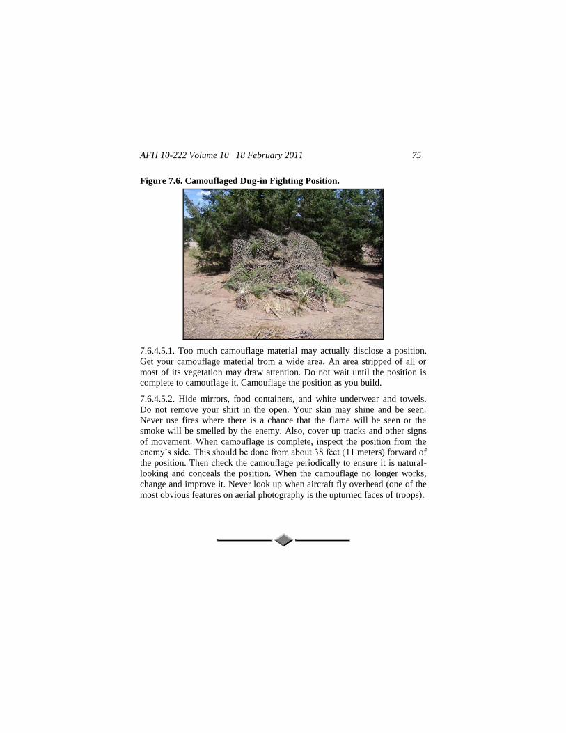
AFH 10-222 Volume 10 18 February 2011 75
Figure 7.6. Camouflaged Dug-in Fighting Position.
7.6.4.5.1. Too much camouflage material may actually disclose a position.
Get your camouflage material from a wide area. An area stripped of all or
most of its vegetation may draw attention. Do not wait until the position is
complete to camouflage it. Camouflage the position as you build.
7.6.4.5.2. Hide mirrors, food containers, and white underwear and towels.
Do not remove your shirt in the open. Your skin may shine and be seen.
Never use fires where there is a chance that the flame will be seen or the
smoke will be smelled by the enemy. Also, cover up tracks and other signs
of movement. When camouflage is complete, inspect the position from the
enemy’s side. This should be done from about 38 feet (11 meters) forward of
the position. Then check the camouflage periodically to ensure it is natural-
looking and conceals the position. When the camouflage no longer works,
change and improve it. Never look up when aircraft fly overhead (one of the
most obvious features on aerial photography is the upturned faces of troops).
AFH 10-222 Volume 10 18 February 2011 76
Chapter 8
DISPERSAL PROCEDURES
8.1. Introduction. Dispersal is the separation or relocation of resources,
preferably away from a threat or pending disaster, for the purpose of increas-
ing survivability. Dispersal creates a smaller target mass for enemy sensors
and weapons systems. Therefore, it reduces casualties and losses in the event
of a natural or manmade disaster or an attack by making enemy detection
efforts more difficult. Dispersion of assets may be necessary at any base:
CONUS, overseas, permanent, contingency, and bare bases. Dispersal can be
incorporated into everyday installation operations through intelligent facility
layout. However, dispersal is usually viewed as an expedient measure to
protect important installation resources from a pending disaster or wartime
threat by temporarily relocating them. Include dispersal plans in the CEMP
10-2, In-Garrison Expeditionary Site Plans (IGESP), and Expeditionary Site
Plans (ESP).
8.2. Planning and Preparing for Dispersal. Effective temporary dispersal
depends upon the circumstance dictating dispersal and the location where
resources are dispersed. For example, dispersing personnel and equipment
into a wooded area prior to a hurricane could cause greater injury and dam-
age from falling branches and trees than if the resources remained in the
open. However, the same action prior to a hostile attack could save lives and
protect equipment by removing them from likely target areas and providing
concealment from enemy forces. As discussed in this handbook, seven steps
are involved in planning and preparing for resource dispersal. Those steps
are outlined in Figure 8.1. and discussed below. Because dispersal is an in-
stallation-wide effort, all units should provide inputs to each step.
8.2.1. Determine the Threats and Identify Vulnerable Resources. As
used here, a threat can be a manmade or natural disaster as well as an enemy
attack. Each installation must decide what threats it faces and which re-
sources are vulnerable for each threat. A threat analysis will determine
whether individual facilities and facility groupings will be dispersed or non-
dispersed, whether electrical and water plants will be dispersed or centrally
located, and whether revetments and airfield damage repair sets will be re-
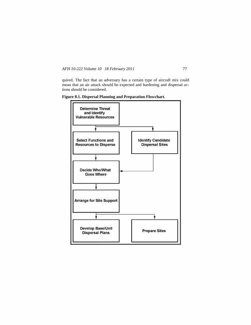
AFH 10-222 Volume 10 18 February 2011 77
quired. The fact that an adversary has a certain type of aircraft mix could
mean that an air attack should be expected and hardening and dispersal ac-
tions should be considered.
Figure 8.1. Dispersal Planning and Preparation Flowchart.
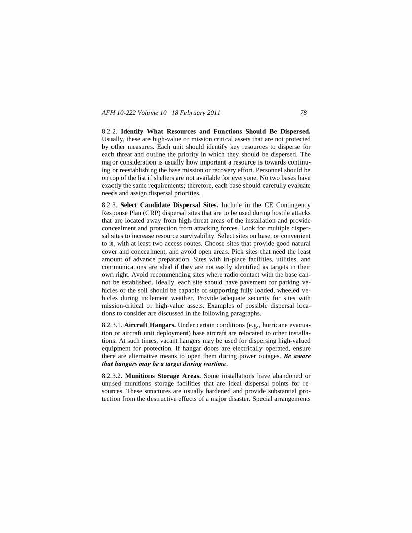
AFH 10-222 Volume 10 18 February 2011 78
8.2.2. Identify What Resources and Functions Should Be Dispersed.
Usually, these are high-value or mission critical assets that are not protected
by other measures. Each unit should identify key resources to disperse for
each threat and outline the priority in which they should be dispersed. The
major consideration is usually how important a resource is towards continu-
ing or reestablishing the base mission or recovery effort. Personnel should be
on top of the list if shelters are not available for everyone. No two bases have
exactly the same requirements; therefore, each base should carefully evaluate
needs and assign dispersal priorities.
8.2.3. Select Candidate Dispersal Sites. Include in the CE Contingency
Response Plan (CRP) dispersal sites that are to be used during hostile attacks
that are located away from high-threat areas of the installation and provide
concealment and protection from attacking forces. Look for multiple disper-
sal sites to increase resource survivability. Select sites on base, or convenient
to it, with at least two access routes. Choose sites that provide good natural
cover and concealment, and avoid open areas. Pick sites that need the least
amount of advance preparation. Sites with in-place facilities, utilities, and
communications are ideal if they are not easily identified as targets in their
own right. Avoid recommending sites where radio contact with the base can-
not be established. Ideally, each site should have pavement for parking ve-
hicles or the soil should be capable of supporting fully loaded, wheeled ve-
hicles during inclement weather. Provide adequate security for sites with
mission-critical or high-value assets. Examples of possible dispersal loca-
tions to consider are discussed in the following paragraphs.
8.2.3.1. Aircraft Hangars. Under certain conditions (e.g., hurricane evacua-
tion or aircraft unit deployment) base aircraft are relocated to other installa-
tions. At such times, vacant hangers may be used for dispersing high-valued
equipment for protection. If hangar doors are electrically operated, ensure
there are alternative means to open them during power outages. Be aware that hangars may be a target during wartime.
8.2.3.2. Munitions Storage Areas. Some installations have abandoned or
unused munitions storage facilities that are ideal dispersal points for re-
sources. These structures are usually hardened and provide substantial pro-
tection from the destructive effects of a major disaster. Special arrangements
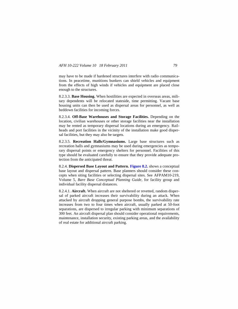
AFH 10-222 Volume 10 18 February 2011 79
may have to be made if hardened structures interfere with radio communica-
tions. In peacetime, munitions bunkers can shield vehicles and equipment
from the effects of high winds if vehicles and equipment are placed close
enough to the structures.
8.2.3.3. Base Housing. When hostilities are expected in overseas areas, mili-
tary dependents will be relocated stateside, time permitting. Vacant base
housing units can then be used as dispersal areas for personnel, as well as
beddown facilities for incoming forces.
8.2.3.4. Off-Base Warehouses and Storage Facilities. Depending on the
location, civilian warehouses or other storage facilities near the installation
may be rented as temporary dispersal locations during an emergency. Rail-
heads and port facilities in the vicinity of the installation make good disper-
sal facilities, but they may also be targets.
8.2.3.5. Recreation Halls/Gymnasiums. Large base structures such as
recreation halls and gymnasiums may be used during emergencies as tempo-
rary dispersal points or emergency shelters for personnel. Facilities of this
type should be evaluated carefully to ensure that they provide adequate pro-
tection from the anticipated threat.
8.2.4. Dispersed Base Layout and Pattern. Figure 8.2. shows a conceptual
base layout and dispersal pattern. Base planners should consider these con-
cepts when siting facilities or selecting dispersal sites. See AFPAM10-219,
Volume 5, Bare Base Conceptual Planning Guide, for facility group and
individual facility dispersal distances.
8.2.4.1. Aircraft. When aircraft are not sheltered or revetted, random disper-
sal of parked aircraft increases their survivability during an attack. When
attacked by aircraft dropping general purpose bombs, the survivability rate
increases from two to four times when aircraft, usually parked at 50-foot
separations, are dispersed to irregular parking with minimum separations of
300 feet. An aircraft dispersal plan should consider operational requirements,
maintenance, installation security, existing parking areas, and the availability
of real estate for additional aircraft parking.
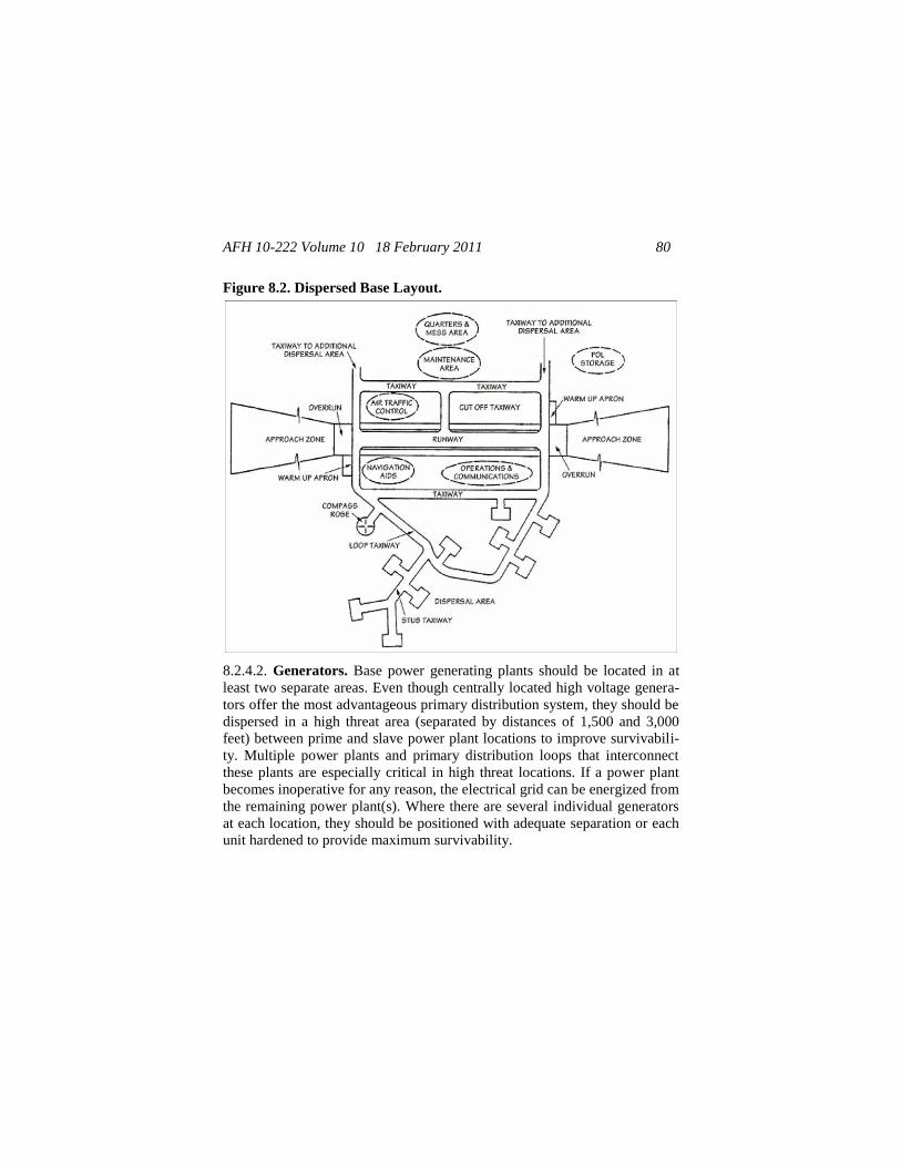
AFH 10-222 Volume 10 18 February 2011 80
Figure 8.2. Dispersed Base Layout.
8.2.4.2. Generators. Base power generating plants should be located in at
least two separate areas. Even though centrally located high voltage genera-
tors offer the most advantageous primary distribution system, they should be
dispersed in a high threat area (separated by distances of 1,500 and 3,000
feet) between prime and slave power plant locations to improve survivabili-
ty. Multiple power plants and primary distribution loops that interconnect
these plants are especially critical in high threat locations. If a power plant
becomes inoperative for any reason, the electrical grid can be energized from
the remaining power plant(s). Where there are several individual generators
at each location, they should be positioned with adequate separation or each
unit hardened to provide maximum survivability.
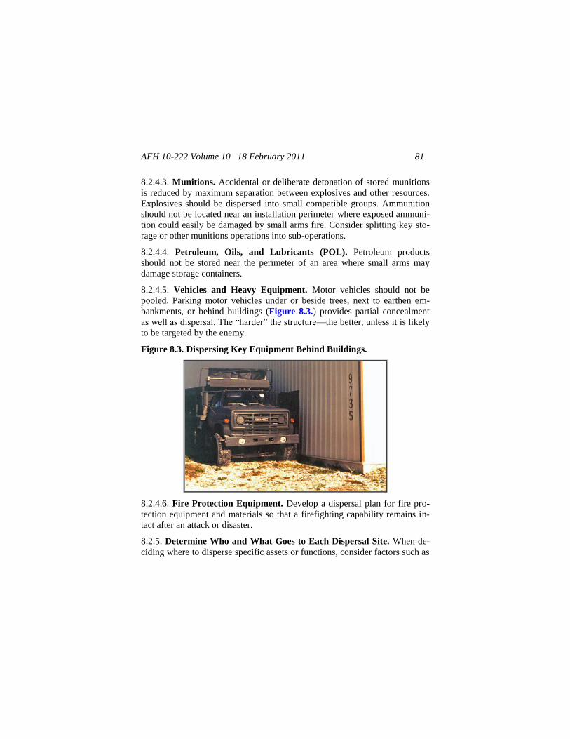
AFH 10-222 Volume 10 18 February 2011 81
8.2.4.3. Munitions. Accidental or deliberate detonation of stored munitions
is reduced by maximum separation between explosives and other resources.
Explosives should be dispersed into small compatible groups. Ammunition
should not be located near an installation perimeter where exposed ammuni-
tion could easily be damaged by small arms fire. Consider splitting key sto-
rage or other munitions operations into sub-operations.
8.2.4.4. Petroleum, Oils, and Lubricants (POL). Petroleum products
should not be stored near the perimeter of an area where small arms may
damage storage containers.
8.2.4.5. Vehicles and Heavy Equipment. Motor vehicles should not be
pooled. Parking motor vehicles under or beside trees, next to earthen em-
bankments, or behind buildings (Figure 8.3.) provides partial concealment
as well as dispersal. The “harder” the structure—the better, unless it is likely
to be targeted by the enemy.
Figure 8.3. Dispersing Key Equipment Behind Buildings.
8.2.4.6. Fire Protection Equipment. Develop a dispersal plan for fire pro-
tection equipment and materials so that a firefighting capability remains in-
tact after an attack or disaster.
8.2.5. Determine Who and What Goes to Each Dispersal Site. When de-
ciding where to disperse specific assets or functions, consider factors such as
AFH 10-222 Volume 10 18 February 2011 82
resource priority, distance to dispersal sites, mobility challenges, and how
much advance warning is likely. Split capabilities and do not cluster vital
assets. Do not concentrate personnel with the same specialty in one spot.
Likewise, do not put all equipment, vehicles, and response teams of the same
type in one place. If possible, keep dispersed personnel within easy walking
distance of their equipment; this improves the success of the dispersal. Air-
field damage repair (ADR) equipment and materials should be dispersed to
at least three separate sites. When selecting dispersed shelters for damage
assessment response teams (DARTs), ensure each team is able to maintain
communications with the unit control center (UCC) either by land line or
radio. Maintain team integrity of DARTs; however, do not place more than
one team in the same dispersed location. This action provides a degree of
redundancy in the event one or more of the shelters is hit. If there is a choice
of shelters for the DARTs, choose shelters that are closest to the UCC. This
eases the reassembly of the teams and subsequent flow of information to the
teams from the UCC. Be careful not to overload a dispersal site.
8.2.6. Arrange for Support Needed at Each Site. Selected services, facili-
ties, utilities, and communications may be required at dispersal sites under
certain circumstances. However, planners should attempt to minimize the
amount of centralized support required at each site; none is the ideal. Units
and individuals should provide their own support whenever possible. Each
person can carry his or her own sleeping bag, food, water, and cold weather
gear. Work details can be formed from each dispersed unit to provide servic-
es such as obtaining water, digging latrines, erecting tents, removing refuse,
and operating the contamination control area (CCA). Identify and consider
resources normally available at the site or in the nearby area. Provide only
limited support in the short term—enough for survival. Increase support as
the duration of the dispersal increases. Each installation must determine its
own priorities for providing this support. As a minimum, consider the fol-
lowing items and provide for them in dispersal plans.
8.2.6.1. Shelters or Tents. Personnel can sleep in or under vehicles for a day
or two if required. Facilities may be required to shelter personnel from the
elements, especially if personnel must disperse frequently or for extended
periods. Units may transport and erect their own tents, if available.
AFH 10-222 Volume 10 18 February 2011 83
8.2.6.2. Sleeping Bags, Blankets, and Cots. Individuals should carry their
own sleeping bags; blankets can substitute for sleeping bags. If not already
issued when the dispersal order is given, make arrangements to have these
items pulled from unit mobility gear storage area, or base supply, and deli-
vered to the dispersal site. This especially applies when dispersing during
cold weather or for long durations. Cots are a nice-to-have item for frequent
or long-term dispersals.
8.2.6.3. Food. Individuals should carry enough Meals, Ready to Eat (MREs)
to last a couple of days; if necessary, units can carry more MREs for longer
periods. Explore food service options with food services if dispersing for
more than seven days.
8.2.6.4. Water. Individuals should disperse with enough water supply to last
at least two days if water is not available at the dispersal site. If water is not
available, make arrangements for delivery after two days. Treating a nearby
water source is an option if equipment is available.
8.2.6.5. Electrical Power. Arrange for generator power and limited distribu-
tion for the few dispersed functions that may need power.
8.2.6.6. Fuel Storage and Dispensing (Vehicle and Heating Fuels). If the
dispersal site is not near the installation, some capability to refuel vehicles
and provide heating fuels may be necessary. A small refueling truck from
base supply is one option. That same truck could also be used to provide fuel
to expedient storage and dispensing points at more than one dispersal site.
Bladders, and even 55-gallon drums, can be used to store or transport fuel.
Even at dispersal sites, fuels must be stored away from shelters and other
resources to minimize the explosive hazard.
8.2.6.7. Sanitation (Latrines and Refuse Collection). Each site must pro-
vide a way to collect and dispose of human and solid waste to prevent a pub-
lic health problem. Expedient latrines are sufficient for human waste. Gener-
ally, a refuse pit periodically covered with a layer of soil is sufficient for
solid waste. Emergency contracting for portable latrines and dumpsters may
be an option. If so, include those plans in the CE CRP.
AFH 10-222 Volume 10 18 February 2011 84
8.2.6.8. Vehicle Maintenance. If necessary, request that the transportation
squadron provide a maintenance capability at the dispersal site, or place a
mobile maintenance truck on standby. Do not forget to make spare parts
available for key equipment. If maintenance and repair procedures are
unique, consider taking maintenance technical orders for special equipment.
8.2.6.9. Communications with Dispersed Forces. Skilled personnel, criti-
cal equipment, and valuable materials are not normally dispersed to an area
and left to operate on their own. To effectively use these forces, command
personnel must maintain communications with dispersal sites. Dispersed
forces must be kept informed of conditions at the base and kept ready to re-
spond. If a dispersal site is permanently established, consider installing a
land line telephone or making cellular phones available to stay in contact
with the base. At sites where a telephone connection is not feasible or when
telephones are inoperative, a radio network can be used. Other communica-
tions measures that may be employed include runners, signal flags, and sig-
nal lights. Any communication method used is appropriate so long as the
message received is the same as the one sent. If signals are used, their mean-
ings must be prearranged and simple. If necessary, use intermediate locations
to relay messages; another dispersal site that is closer to the main base could
serve this function. When making plans, the base must decide who maintains
contact with the dispersed forces: the installation control center (ICC), the
emergency operations center (EOC), or UCC for their own personnel. For
multiple on-base sites, UCCs can generally perform a better job. At off-base
sites with multiple organizations, the ICC or the EOC may elect to maintain
communications and provide direction.
8.2.6.10. Transportation. Determine how personnel, vehicles, and equip-
ment will be moved. This can be a unit responsibility, a consolidated base
effort, or a combination. For extended dispersals prior to hostilities, units
may use their own vehicles to transport personnel and equipment as required.
Base shuttles may be set up to run scheduled routes for long-term dispersals.
8.2.6.11. Contamination Control Area (CCA) Operations. In a CBRN
environment, dispersal sites should be in toxic-free areas if possible. To
process personnel, vehicles, and equipment into and out of the dispersal site,
a contamination control area and a vehicle/equipment decontamination sta-
AFH 10-222 Volume 10 18 February 2011 85
tion must be set up, manned, and operated. The responsibility for these tasks
can be assigned to one unit permanently, to all units on a rotation, or to CCA
teams formed by detailing individuals from the different units at the site. For
around-the-clock operations, at least two—preferably three—CCA teams are
required. Decide who will set up the CCA and who will supervise the CCA
teams. See AFMAN 32-4005, Personnel Protection and Attack Actions,
(until rescinded by AFMAN 10-2502 Series publications) for tips on CCA
set up. Plans should specify who will obtain, store, and maintain CCA
equipment and materials.
8.2.6.12. Security. At on-base sites, units should expect to provide security
for their own assets. This does not mean the assets have to be guarded on a
full-time basis; each installation and situation is different. Civil engineers
should work out details with the security forces. When off base at overseas
locations, additional security is required. Depending upon the location, the
civilian countryside surrounding an overseas airbase may be relatively
peaceful or extremely hostile. Even during peacetime dispersals, security
remains an important consideration. Resources available from base security
forces, US Army units, or host nation security forces determine the level of
protection available to dispersed assets. Civil engineers and other units at the
dispersal site may be called upon to assist security forces.
8.2.7. Develop Base and Unit Dispersal Plans. The base plan (CEMP 10-2)
provides the big picture, such as what units disperse and where. The unit
dispersal plans (CE CRP) identify what specific resources and which per-
sonnel disperse and how dispersal is accomplished.
8.2.7.1. Base Dispersal. The base dispersal plan should detail which units
disperse, where each goes, under what conditions dispersal will be neces-
sary, the priority of the resources, who provides what support, and the com-
mand and control structure. When more than one unit is dispersed to the
same location, the plan may outline which part of the site each unit occupies.
However, do not expect this level of detail very often. The plan should clear-
ly outline the command and control structure, especially for off-base sites, to
control the initial chaos and to direct site operations during extended stays. It
is reasonable to expect that the senior ranking person will be in charge. The
plan could also designate a lead unit and the senior person of that unit to be
AFH 10-222 Volume 10 18 February 2011 86
in charge. Civil engineers should be prepared to offer recommendations to
the senior leader with regard to “facility” siting, utilities, sanitation, harden-
ing, and CCA operations. Do not discuss locations of off-base wartime dis-
persal sites. Keeping them a secret may be impossible, but do not draw atten-
tion to them. Have enough alternate sites established so you can keep an
enemy guessing where the actual dispersal site is located. When dispersal
plans are exercised, alternate deployments between each site to avoid tipping
off which site is favored among all locations. If dispersal plans are to another
installation or location far from the home base, convoys or other mass trans-
portation efforts will have to be planned.
8.2.7.2. Unit Dispersal. The unit plan provides the specifics. It should iden-
tify personnel, equipment, and vehicles to disperse, in what priority order,
and to what location. Specify who moves which vehicles and equipment
items, and designate where repair materials will be located. The methods of
dispersal are generally determined by the distance to the dispersal site. Po-
wered equipment may be driven to dispersal sites on base; other equipment
may be transported by truck or similar vehicle, or personnel may physically
carry smaller pieces of equipment and materials. To the greatest extent poss-
ible, disperse resources by teams.
8.2.7.2.1. Create dispersal checklists and load plans. The checklists should
include items such as obtaining food, water, sleeping bags, chemical warfare
ensembles, tents, camouflage netting, hand tools, shovels, picks, sandbags,
extra consumables (oil, grease, hydraulic fluid, air filters, etc.), and vehicle
servicing supplies (fuel, engine oil, air in tires, jacks, spare tires, etc.). The
load plans should identify what items are to be loaded on each vehicle. Load
plans minimize confusion and ensure the most important assets are moved
first.
8.2.7.2.2. If possible, inspect designated dispersal sites in advance. Deter-
mine what site improvements are required before and after dispersal. Decide
what support items should be taken and estimate how much.
8.2.7.2.3. Perform operational checks and service equipment before disper-
sal. To save time later, load vehicles with repair materials likely needed early
on during base recovery.
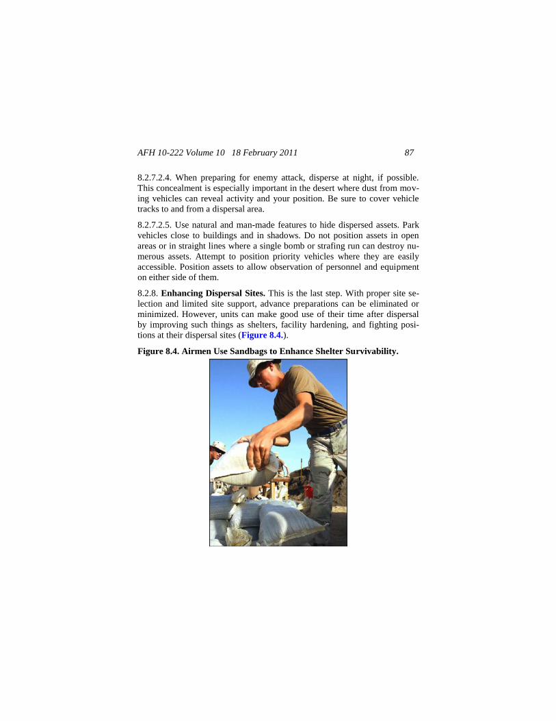
AFH 10-222 Volume 10 18 February 2011 87
8.2.7.2.4. When preparing for enemy attack, disperse at night, if possible.
This concealment is especially important in the desert where dust from mov-
ing vehicles can reveal activity and your position. Be sure to cover vehicle
tracks to and from a dispersal area.
8.2.7.2.5. Use natural and man-made features to hide dispersed assets. Park
vehicles close to buildings and in shadows. Do not position assets in open
areas or in straight lines where a single bomb or strafing run can destroy nu-
merous assets. Attempt to position priority vehicles where they are easily
accessible. Position assets to allow observation of personnel and equipment
on either side of them.
8.2.8. Enhancing Dispersal Sites. This is the last step. With proper site se-
lection and limited site support, advance preparations can be eliminated or
minimized. However, units can make good use of their time after dispersal
by improving such things as shelters, facility hardening, and fighting posi-
tions at their dispersal sites (Figure 8.4.).
Figure 8.4. Airmen Use Sandbags to Enhance Shelter Survivability.
AFH 10-222 Volume 10 18 February 2011 88
8.3. Hasty Planning and Preparations. Ideally, dispersal planning is ac-
complished during the leisure of peacetime, but not every contingency can
be foreseen. If the unit only has time for hasty planning, the common sense
steps outlined above still apply. Just do not labor over the options. Quickly
decide which of your resources are most important to protect and go with the
most obvious. From personal knowledge of the installation and the surround-
ing area, determine which sites are best for dispersal. Decide how to move
the resources and who will do it. Determine what communication methods
will be used to keep all unit personnel informed, and ensure all personnel
understand how this is to be accomplished when dispatched. Ideally, each
vehicle group traveling between the installation and a dispersal site should
have at least one working radio.
8.4. CE Dispersal in Continental US (CONUS). The primary purpose of
dispersal in CONUS is to escape the destruction of natural disasters and to
get personnel and priority assets out of harm’s way. Some installations may
support a survival, recovery, and reconstitution (SRR) plan which calls for
dispersal.
8.4.1. On-Base Dispersal. When establishing CONUS on-base dispersal
sites, resources should be identified for pre-positioning to save time during
dispersal. Materials that have extended shelf lives, such as sand, gravel, and
other building items, are suitable candidates for pre-positioning at dispersal
sites. A fuel storage facility at dispersal locations ensures continued opera-
tion of dispersed vehicles if primary fuel storage facilities are damaged or
destroyed. If personnel are dispersed for an extended period of time, utilities,
billeting, and food service will be required.
8.4.2. Dispersal to Other Military Installations. If the civil engineer unit is
required to disperse resources to another installation during an emergency,
numerous details must be considered. Transportation arrangements are a
primary concern. When reasonable distances are involved, a truck convoy
may constitute the best method. Qualified personnel should supervise the
loading and movement of the convoy. Seemingly insignificant details over-
looked during transportation planning have a tendency to become large prob-
lems during convoy movements. During disasters, as in war, transportation
routes tend to become overloaded with military and civilian traffic. Sound
AFH 10-222 Volume 10 18 February 2011 89
convoy procedures should be followed. Close coordination with the receiv-
ing installation is essential. The BCE should appoint an experienced person
to coordinate billeting and food service support upon arrival at the final des-
tination. Communications capabilities should also be assessed to ensure that
contact can be maintained with the dispersing force throughout the move-
ment and subsequent stay at the dispersal site.
8.4.3. Dispersal to Civilian Locations. If a situation arises where dispersal
to civilian locations becomes necessary under peacetime conditions, the Base
Civil Engineer (BCE) must ensure that close coordination is established with
local property owners and civilian government officials. Approval of the
property owner must be obtained, and civil engineer personnel must careful-
ly document any property damage that occurs as a result of the dispersal.
This documentation greatly facilitates the handling of any claims for reim-
bursement following the dispersal. If civilian dispersal locations are a rea-
sonable alternative for a CONUS BCE during a peacetime emergency, con-
sider negotiating prior use or rental agreements with civilian property owners
or local community officials. Dispersal to civilian locations should only be
done after careful consideration of on-base and other military base alterna-
tives.
8.5. CE Dispersal Outside the Continental United States (OCONUS).
Dispersal as a means of resource protection overseas is accomplished for
many of the same reasons as in the CONUS. In addition, consider dispersal
as a means of protecting resources from chemical, biological, radiological,
nuclear, and high yield explosives (CBRNE) attacks. Forces OCONUS
might be dispersed to a remote location on base, to a collocated operating
base (COB), or to a civilian location.
8.5.1. On-Base Dispersal Locations. Engineers overseas, like their CONUS
counterparts, should select locations on the main base which provide opti-
mum protection against any foreseeable disaster. An area of difference is
protection against CBRNE attacks. The overseas air base is more vulnerable
to a CBRNE attack than a CONUS location; therefore, emphasis should be
given to selecting multiple dispersal sites removed from the likely target
areas of the installation. Dispersal locations removed from prime air base
target areas (such as runways, command and control centers, POL facilities,
AFH 10-222 Volume 10 18 February 2011 90
and munitions storage areas) contribute to the preservation of resources dur-
ing an attack. Once these sites have been identified, develop physical protec-
tion methods for each location as further resource protection. Fire Emergen-
cy Services (FES) should be located in close proximity to the operational
infrastructure and should be given special consideration for dispersal loca-
tions, concealment, and physical protection.
8.5.2. COB Dispersal Locations. A COB is an allied installation that can be
used to beddown augmenting forces. Close coordination with the host instal-
lation agencies is a primary requirement during any dispersal to a COB. An
important aspect of dispersal to a COB is the cultural, procedural, and lan-
guage differences that civil engineer personnel must overcome.
8.5.3. Dispersal to Civilian Locations. Dispersal to a civilian location in an
overseas environment is much more complicated than it would be in a
CONUS area. The laws of each country differ, and there may be no existing
status-of-forces agreements for obtaining rights to use local property as a
dispersal site. Again, the base must evaluate needs and determine if off-base
dispersal sites would serve a useful purpose. If these sites are determined to
be necessary, discuss the possibility of negotiated agreements with the base
legal staff, your MAJCOM, and representatives of the host government. Ne-
gotiations with foreign property owners are best left to members of the host
government.
8.6. Summary. Temporary dispersal is a relatively inexpensive and expe-
dient method to protect important installation assets from the effects of dis-
asters and enemy attack, but some advance warning is required to mobilize
personnel and assets. The value of wartime dispersal can be improved by
employing supplemental protection and hardening measures.
AFH 10-222 Volume 10 18 February 2011 91
Chapter 9
INFORMATION COLLECTION, RECORDS, AND FORMS
9.1. Information Collections. No information collections are created by this
publication.
9.2. Records. The program records created as a result of the processes pre-
scribed in this publication are maintained in accordance with AFMAN 33-
363 and disposed of in accordance with the Air Force RDS located at
https://www.my.af.mil/afrims/afrims/afrims/rims.cfm.
9.3. Forms (Adopted and Prescribed).
9.3.1. Adopted Forms: AF Form 847, Recommendation for Change of Publication.
9.3.2. Prescribed Forms. No prescribed forms are implemented in this publi-
cation.
HERBERT J. CARLISLE, Lt General, USAF
DCS/Operations, Plans, and Requirements (A3/5)
AFH 10-222 Volume 10 18 February 2011 92
Attachment 1
GLOSSARY OF REFERENCES
AND
SUPPORTING INFORMATION
References
AFDD2-4, Combat Support, 23 Mar 2005
AFDD2-34, Engineer Operations, Under Development
AFI10-210, Prime Base Engineer Emergency Force (BEEF), 21 Mar 2008
AFI10-211, Civil Engineer Contingency Response Planning, 22 Sep 2008
AFI10-245, Antiterrorism (AT), 30 Mar 2009
AFI10-404, Base Support and Expeditionary Site Planning, 9 Mar 2004
AFI10-704, Military Deception Program, 30 Aug 2005
AFI10-2501, Air Force Emergency Management (EM) Program Planning
and Operations, 24 Jan 2007 (Change 2)
AFTTP3-10.1, Integrated Base Defense (IBD), 20 Aug 2004
AFMAN 32-4005, Personnel Protection and Attack Actions, 30 Oct 2001
AFPAM10-219, Volume 2, Civil Engineer Disaster and Attack Prepara-
tions, 9 Jun 2008
AFPAM10-219, Volume 5, Bare Base Conceptual Planning Guide, 1 Jun
1996
AFPD10-2, Readiness, 30 Oct 2006
FM3-21.75, The Warrior Ethos and Soldier Combat Skills, Jan 2008
FM3-50, Smoke Operations, 4 Dec 1990
FM5-103, Survivability, 10 Jun 1985
FM20-3, Camouflage, Concealment, and Decoys, 30 Aug 1999
AFH 10-222 Volume 10 18 February 2011 93
JP3-01, Countering Air and Missile Threats, 5 Feb 2007
TM5-304, Army Facilities Components System User Guide, Oct 1990
TO11WA2-1-1, Lightweight Camouflage Screen Systems and Support Sys-
tems, 30 Sep 1982
Abbreviations and Acronyms
ABU—Airman Battle Uniform
ADR—airfield damage repair
AFOSI—Air Force Office of Special Investigations
AFRIMS—Air Force Records Information Management System
AO—area of operation
AT—Antiterrorism
BCE—Base Civil Engineer
C2—command and control
CBRN—chemical, biological, radiological, and nuclear
CBRNE—chemical, biological, radiological, nuclear, and high yield explo-
sives
CCA—contamination control area
CCD—camouflage, concealment, and deception
CEMP—Comprehensive Emergency Management Plan
COB—collocated operating base
COMSEC—communications security
CONUS—Continental United States
CP—command post
CSS—combat service support
AFH 10-222 Volume 10 18 February 2011 94
DART—damage assessment and repair team
DISO—deception in support of OPSEC
EM—electromagnetic
EM spectrum—electromagnetic spectrum
EOC—Emergency Operations Center
ESP—Expeditionary Site Plan
FARP—forward arming and refueling point
FES—Fire Emergency Services
FLIRS—Forward-Looking Infrared System
FM—field manual
FOD—foreign object damage
FOS—false operating surfaces
gal—gallon
GI—government issue
GSU—geographically separated unit
HQ—headquarters
HVT—high-value target
IBD—integrated base defense
ICC—Installation Control Center
IGESP—In-garrison Expeditionary Site Plan
IPB—intelligence preparation of the battlefield
IR—infrared
LCSS—Lightweight Camouflage Screen System
AFH 10-222 Volume 10 18 February 2011 95
LLTV—low-light television
LOC—lines of communication
LOS—line of sight
MAJCOM—Major Command
MDO—Military Deception Officer
MDNCO—Military Deception NCO
METT-TC—mission, enemy, terrain, weather, troops, time available, and
civilian considerations
MHz—megahertz
MILDEC—military deception
MRE—meals ready to eat
MTI—moving target indicator
NCO—noncommissioned officer
NIR—near infrared
NSN—national stock number
NVD—night-vision device
OCONUS—outside the Continental United States
OPSEC—operations security
POL—petroleum, oils, and lubricants
RAM—radar-absorbing material
RAP—radar absorbing paint
RATELO—radiotelephone operator
RCS—radar cross section
RDS—Records Disposition Schedule
AFH 10-222 Volume 10 18 February 2011 96
Recon—reconnaissance
RSTA—reconnaissance, surveillance, and target acquisition
SCSPP—standard camouflage screening paint pattern
SF—Security Forces
SOP—standing operating procedure
SRR—survival, recovery, and reconstitution
Tac-D—tactical deception
TV—television
TWG—Threat Working Group
UAV—unmanned aerial vehicle
UCC—Unit Control Center
US—United States
UV—ultraviolet
VHF—very high frequency
WSA—weapons storage area
Terms
Blending—A CCD technique that causes a target to appear as part of the
background. Many target characteristics must be considered when attempt-
ing a blending treatment, including target size and shape, regular patterns in
the target scene, and rough or smooth target contours.
Camouflage net—Part of a system designed to blend a target with its sur-
roundings and conceal the identity of critical assets (aircraft, fixed targets,
vehicles, personnel) where natural cover and/or concealment might be absent
or inadequate.
AFH 10-222 Volume 10 18 February 2011 97
Camouflage net spreader—A plastic or aluminum disc or paddle that is
supported by a lightweight pole and used to support camouflage nets above
the ground, buildings, or vehicles.
camouflage, concealment, and decoys—Methods and resources to prevent
adversary observation or surveillance; confuse, mislead, or evade the adver-
sary; or induce the adversary to act in a manner prejudicial to his interests.
CCD treatment—A combination of CCD equipment and techniques applied
to a selected target and/or its background to reduce or delay target acquisi-
tion.
Countermeasure—Any technique intended to confuse or mislead hostile
sensors.
Concealment—The protection from observation or surveillance
Corner reflector—An object that reflects multiple signals from smooth sur-
faces mounted mutually perpendicular and produces a radar return of greater
magnitude than expected from the size of the object the reflector conceals.
Cover—Any natural or artificial protection from enemy observation and
fire.
Deceive—Any action that causes the enemy to believe the false or purposely
causes the enemy to make incorrect conclusions based on false evidence.
Deception—Those measures designed to mislead the enemy by manipula-
tion, distortion, or falsification of evidence, inducing him to react in a man-
ner prejudicial to his interests.
Deception in support of Operations Security—A military deception activi-
ty that protects friendly operations, personnel, programs, equipment, and
other assets from foreign intelligence security services (FISS) collection.
Decoy—An imitation in any sense of a person, an object, or a phenomenon
that is intended to deceive enemy surveillance devices or mislead enemy
evaluation. (DISO).
Defilade—Protection or shielding from hostile ground observation and flat
projecting fire provided by an artificial or natural obstacle, as a hill.
AFH 10-222 Volume 10 18 February 2011 98
Detection—The discovery of an existence or presence
Disguise—Any alteration of identity cues for items, signals, or systems suf-
ficient to cause misidentification by the enemy.
Dispersal—Relocation of forces for the purpose of increasing survivability
Disrupt—Any action intended to interrupt the shape or outline of an object
or an individual, making it less recognizable.
electromagnetic spectrum—The range of frequencies from zero to infinity
where energy is transferred by electric and magnetic waves. EM waves at the
lower end of this spectrum (low-frequency navigation aids and AM and
shortwave radio services) are refracted back to earth by the ionosphere to
frequencies as high as 50 MHz. At frequencies above 50 MHz, propagation
is generally limited to LOS. These frequencies are used by TV, FM radio,
and land-mobile and point-to-point communication services. They extend on
to parts of the EM spectrum generally termed as radar, IR, visible light, UV
light, and cosmic rays.
Forward-Looking Infrared System—An imaging IR sensor used to ac-
quire a target's heat signature.
Hardening—The construction of a facility to provide protection against the
effects of conventional or nuclear explosions. The facility may also be
equipped to provide protection against chemical or biological attacks. Con-
struction usually involves reinforced concrete placement and/or burying the
structure.
Hiding—The choice of a position or materials to obstruct direct observation
Hyperspectral—Refers to a sensor or data with many bands extending over
a range of the EM spectrum.
Imaging radar—An electronic or optical process for recording or display-
ing a scene generated by a radar sensor.
intelligence preparation of the battlefield—A systematic approach to ana-
lyzing the enemy, weather, and terrain in a specific geographic area. It inte-
grates enemy doctrine with the weather and terrain conditions as they relate
AFH 10-222 Volume 10 18 February 2011 99
to the mission and the specific battlefield environment. IPB provides the
framework for determining and evaluating enemy capabilities, vulnerabili-
ties, and probable courses of action.
Joint Military Deception—Joint MILDEC is planned and conducted in a
theater of operations to support military campaigns and major military opera-
tions. Joint MILDEC activities are planned and executed by, and in support
of, Combatant Commanders, Joint Force Commanders, and Joint Task Force
Commanders to cause adversaries to take actions that are favorable to the US
commander’s objectives. The majority of combatant command planned and
executed MILDEC will be Join MILDEC with operational-level effects. Join
MILDEC is normally planned prior to, and conducted during, combat opera-
tions. (Joint MILDEC)
Low emissivity paint—Paint used to lower the apparent temperature of a
target (or nearby scene features), thus making the hot target less conspicuous
to a thermal target-acquisition sensor. Using a paint that has too low an
emissivity (less than 0.6) causes the target to become more visually conspi-
cuous (or shiny).
military deception—Military deception are actions executed to deliberately
mislead adversary military, paramilitary, or violent extremist organizations
decision makers, thereby causing the adversary to take specific actions (or
inactions) that will contribute to the accomplishment of the friendly mission
(MILDEC).
Movement techniques—The methods used by a unit to travel from one
point to another (traveling, traveling overwatch, and bounding overwatch)
are considered movement techniques. The likelihood of enemy contact de-
termines which technique is used.
Multispectral—Refers to a sensor or data in two or more regions of the EM
spectrum.
operations security—The process of denying adversaries information about
friendly capabilities and intentions by identifying, controlling, and protecting
signatures associated with planning for and conducting military operations
AFH 10-222 Volume 10 18 February 2011 100
and other activities. It includes countersurveillance and physical, signal, and
information security.
Radar—A device that uses EM waves to provide information on the range,
the azimuth, or the elevation of objects.
Radio direction-finding—The act of determining the azimuth to a radio
transmitter, from a specific location, using signal-detecting equipment.
radar-absorbing material—Material that absorbs and dissipates incident
radar energy as contrasted to radar-scattering material, which reflects the
incident energy in a different direction.
radar cross section—The size of a conducting square, metal plate that
would return the same signal to a radar sensor as a target, provided that the
radar energy received at the target is reradiated equally in all directions.
Reconnaissance—An exploratory survey of a particular area or airspace by
visual, aural, electronic, photographic, IR, or other means. It may imply a
physical visit to the area.
Redundancy—The use of multiple systems with similar perceived function-
al capabilities to provide higher system survivability.
Reverse-slope—A position on the ground that is not exposed to direct fire or
observation; for example, a slope that descends away from the enemy.
Revetment—A barrier used to protect assets against attack.
Signature—Detectable indications that forces are occupying or operating in
an area. Signatures can be EM (visible, IR, NIR, radar) or mechanical
(acoustic, seismic). Common detectable EM signatures include visible ve-
hicle tracks, thermal flames, and radar signal returns. Common mechanical
signatures include radio noise, humans conversing, and seismic ground
waves produced by tanks and heavy vehicles.
Smoke screen—Smoke generated to deceive or confuse an enemy as to the
activities of tactical elements.
Surveillance—A systematic observation of airspace or surface areas by vis-
ual, aural, electronic, photographic, IR, or other means.
AFH 10-222 Volume 10 18 February 2011 101
Tactical Deception—MILDEC planned to support battles and engagements.
Tactical MILDEC activities are planned and executed by, and in support of,
tactical-level commanders to cause foreign entity actions that are favorable
to the U.S. commanders’ objectives. Tactical MILDEC is conducted to in-
fluence immediate combat operations in order to gain a temporary tactical
advantage over and adversary, to mask vulnerabilities in friendly forces, or
to enhance the defensive capabilities of friendly forces. Tactical MILDEC is
usually “nested” with other operations as part of the combatant command’s
join MILDCE plan. (Tac-D)
Target acquisition—The process involving the detection and identification
of hostile operations and equipment for subsequent engagement.
Target scene—The view of a target area that includes both the target and its
surroundings.
Terrain mottling—A camouflage technique normally used in desert terrain.
It involves scarring the earth with heavy equipment to expose patches of bare
ground. Equipment and supplies are placed on the bare patches to avoid de-
tection by aerial reconnaissance.
Thermal contrast—The difference in radiance (as usually measured in the
8-to-14 micron band) between two features of a scene; for example, a target
and its background.
Tone down—The process of blending a target or other high-value asset with
the background by reducing its brightness characteristics using nets or coat-
ings. The recommended reflectance of a target as compared with the sur-
rounding scene is 10 percent or less.
Wadis—The channel of a watercourse that is dry except during periods of
rainfall
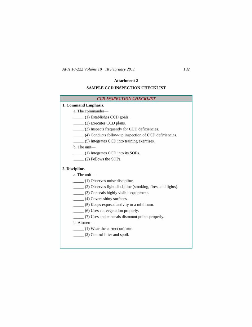
AFH 10-222 Volume 10 18 February 2011 102
Attachment 2
SAMPLE CCD INSPECTION CHECKLIST
CCD INSPECTION CHECKLIST
1. Command Emphasis.
a. The commander—
_____ (1) Establishes CCD goals.
_____ (2) Executes CCD plans.
_____ (3) Inspects frequently for CCD deficiencies.
_____ (4) Conducts follow-up inspection of CCD deficiencies.
_____ (5) Integrates CCD into training exercises.
b. The unit—
_____ (1) Integrates CCD into its SOPs.
_____ (2) Follows the SOPs.
2. Discipline.
a. The unit—
_____ (1) Observes noise discipline.
_____ (2) Observes light discipline (smoking, fires, and lights).
_____ (3) Conceals highly visible equipment.
_____ (4) Covers shiny surfaces.
_____ (5) Keeps exposed activity to a minimum.
_____ (6) Uses cut vegetation properly.
_____ (7) Uses and conceals dismount points properly.
b. Airmen—
_____ (1) Wear the correct uniform.
_____ (2) Control litter and spoil.
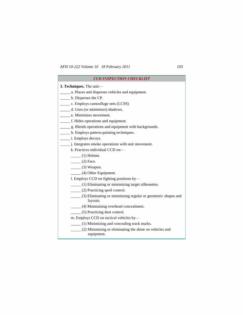
AFH 10-222 Volume 10 18 February 2011 103
CCD INSPECTION CHECKLIST
3. Techniques. The unit—
_____ a. Places and disperses vehicles and equipment.
_____ b. Disperses the CP.
_____ c. Employs camouflage nets (LCSS)
_____ d. Uses (or minimizes) shadows.
_____ e. Minimizes movement.
_____ f. Hides operations and equipment.
_____ g. Blends operations and equipment with backgrounds.
_____ h. Employs pattern-painting techniques.
_____ i. Employs decoys.
_____ j. Integrates smoke operations with unit movement.
k. Practices individual CCD on—
_____ (1) Helmet.
_____ (2) Face.
_____ (3) Weapon.
_____ (4) Other Equipment.
l. Employs CCD on fighting positions by—
_____ (1) Eliminating or minimizing target silhouettes.
_____ (2) Practicing spoil control.
_____ (3) Eliminating or minimizing regular or geometric shapes and
layouts.
_____ (4) Maintaining overhead concealment.
_____ (5) Practicing dust control.
m. Employs CCD on tactical vehicles by—
_____ (1) Minimizing and concealing track marks.
_____ (2) Minimizing or eliminating the shine on vehicles and
equipment.
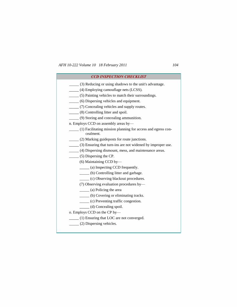
AFH 10-222 Volume 10 18 February 2011 104
CCD INSPECTION CHECKLIST
_____ (3) Reducing or using shadows to the unit's advantage.
_____ (4) Employing camouflage nets (LCSS).
_____ (5) Painting vehicles to match their surroundings.
_____ (6) Dispersing vehicles and equipment.
_____ (7) Concealing vehicles and supply routes.
_____ (8) Controlling litter and spoil.
_____ (9) Storing and concealing ammunition.
n. Employs CCD on assembly areas by—
_____ (1) Facilitating mission planning for access and egress con-
cealment.
_____ (2) Marking guideposts for route junctions.
_____ (3) Ensuring that turn-ins are not widened by improper use.
_____ (4) Dispersing dismount, mess, and maintenance areas.
_____ (5) Dispersing the CP.
(6) Maintaining CCD by—
_____ (a) Inspecting CCD frequently.
_____ (b) Controlling litter and garbage.
_____ (c) Observing blackout procedures.
(7) Observing evaluation procedures by—
_____ (a) Policing the area
_____ (b) Covering or eliminating tracks.
_____ (c) Preventing traffic congestion.
_____ (d) Concealing spoil.
o. Employs CCD on the CP by—
_____ (1) Ensuring that LOC are not converged.
_____ (2) Dispersing vehicles.
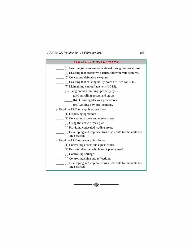
AFH 10-222 Volume 10 18 February 2011 105
CCD INSPECTION CHECKLIST
_____ (3) Ensuring turn-ins are not widened through improper use.
_____ (4) Ensuring that protective barriers follow terrain features.
_____ (5) Concealing defensive weapons.
_____ (6) Ensuring that existing utility poles are used for LOC.
_____ (7) Maintaining camouflage nets (LCSS).
(8) Using civilian buildings properly by—
_____ (a) Controlling access and egress.
_____ (b) Observing blackout procedures.
_____ (c) Avoiding obvious locations.
p. Employs CCD on supply points by—
_____ (1) Dispersing operations.
_____ (2) Concealing access and egress routes.
_____ (3) Using the vehicle track plan.
_____ (4) Providing concealed loading areas.
_____ (5) Developing and implementing a schedule for the units be-
ing serviced.
q. Employs CCD on water points by—
_____ (1) Concealing access and egress routes.
_____ (2) Ensuring that the vehicle track plan is used.
_____ (3) Controlling spillage.
_____ (4) Controlling shine and reflections.
_____ (5) Developing and implementing a schedule for the units be-
ing serviced.
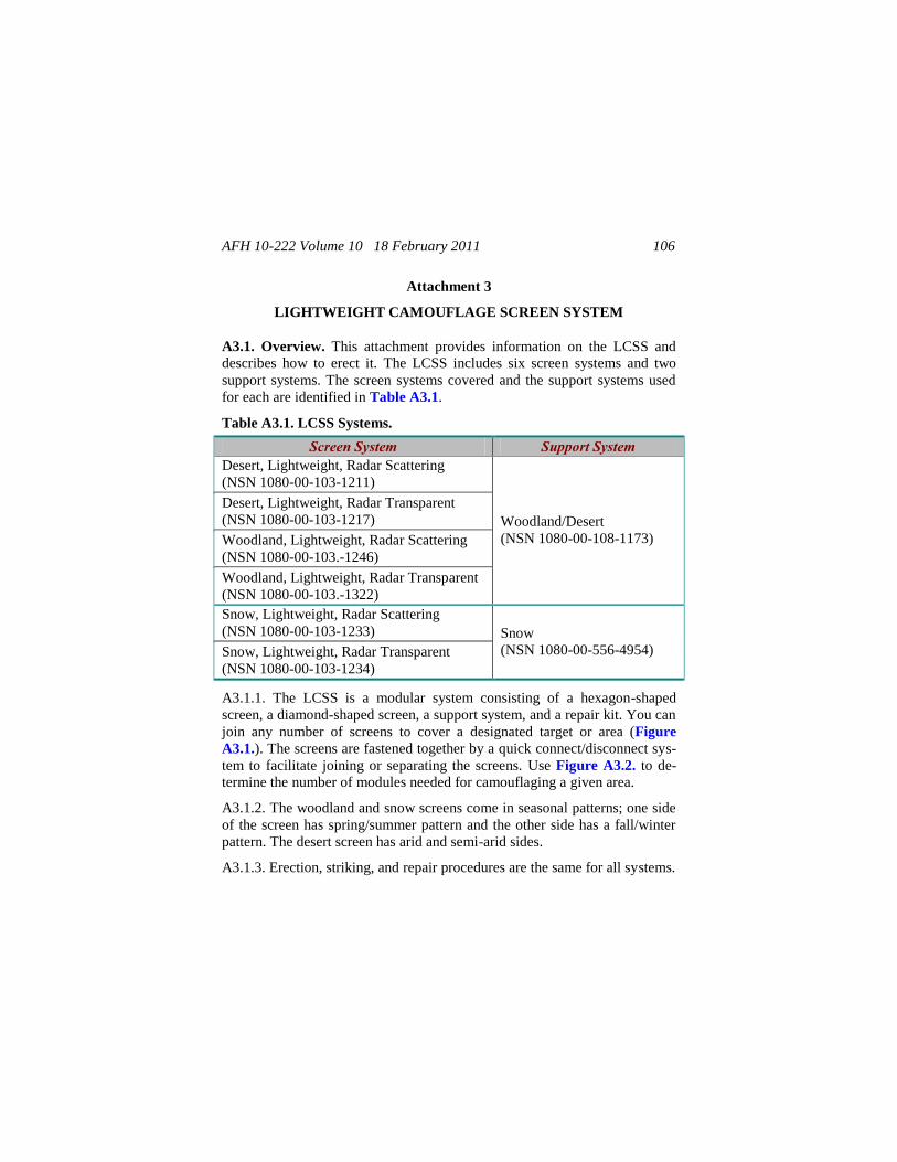
AFH 10-222 Volume 10 18 February 2011 106
Attachment 3
LIGHTWEIGHT CAMOUFLAGE SCREEN SYSTEM
A3.1. Overview. This attachment provides information on the LCSS and
describes how to erect it. The LCSS includes six screen systems and two
support systems. The screen systems covered and the support systems used
for each are identified in Table A3.1.
Table A3.1. LCSS Systems.
Screen System Support System Desert, Lightweight, Radar Scattering
(NSN 1080-00-103-1211)
Woodland/Desert
(NSN 1080-00-108-1173)
Desert, Lightweight, Radar Transparent
(NSN 1080-00-103-1217)
Woodland, Lightweight, Radar Scattering
(NSN 1080-00-103.-1246)
Woodland, Lightweight, Radar Transparent
(NSN 1080-00-103.-1322)
Snow, Lightweight, Radar Scattering
(NSN 1080-00-103-1233) Snow
(NSN 1080-00-556-4954) Snow, Lightweight, Radar Transparent
(NSN 1080-00-103-1234)
A3.1.1. The LCSS is a modular system consisting of a hexagon-shaped
screen, a diamond-shaped screen, a support system, and a repair kit. You can
join any number of screens to cover a designated target or area (Figure
A3.1.). The screens are fastened together by a quick connect/disconnect sys-
tem to facilitate joining or separating the screens. Use Figure A3.2. to de-
termine the number of modules needed for camouflaging a given area.
A3.1.2. The woodland and snow screens come in seasonal patterns; one side
of the screen has spring/summer pattern and the other side has a fall/winter
pattern. The desert screen has arid and semi-arid sides.
A3.1.3. Erection, striking, and repair procedures are the same for all systems.
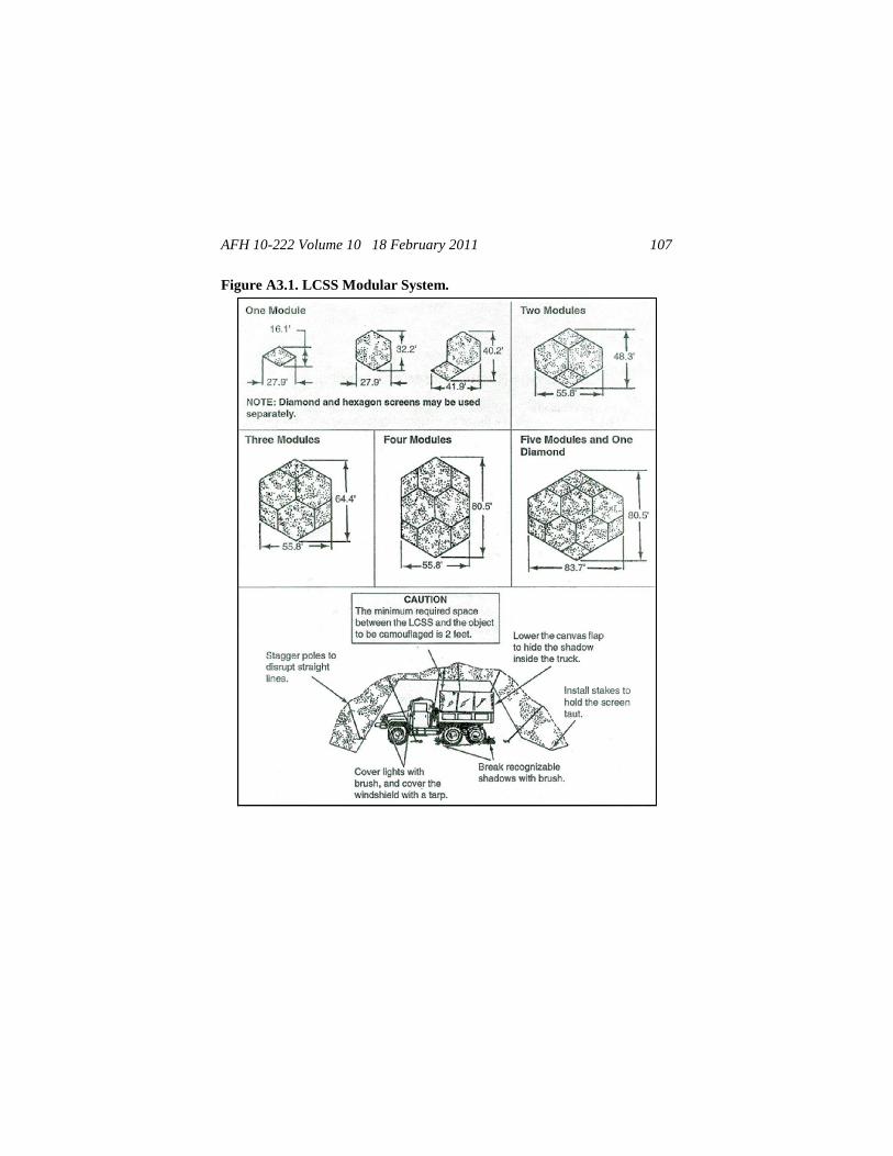
AFH 10-222 Volume 10 18 February 2011 107
Figure A3.1. LCSS Modular System.
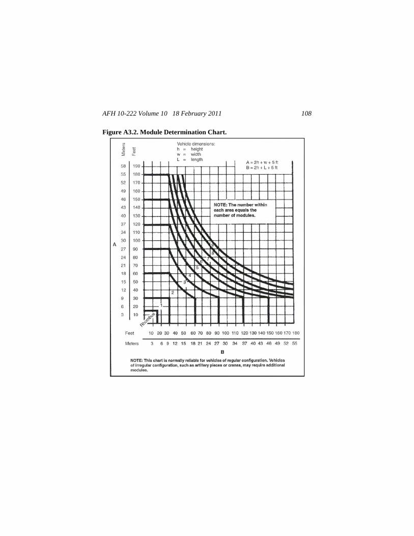
AFH 10-222 Volume 10 18 February 2011 108
Figure A3.2. Module Determination Chart.
AFH 10-222 Volume 10 18 February 2011 109
A3.2. Capabilities. The LCSS protects targets in four different ways:
A3.2.1. Casts patterned shadows that break up the characteristic outlines of a
target.
A3.2.2. Scatters radar returns (except when radar-transparent nets are used).
A3.2.3. Traps target heat and allows it to disperse.
A3.2.4. Simulates color and shadow patterns that are commonly found in a
particular region.
A3.3. Supplemental Camouflage. Camouflage nets are often employed in
conjunction with supplemental camouflage because nets alone do not make a
target invisible to a threat's multispectral sensors. Use other CCD techniques
to achieve effective concealment. Cover or remove all of the target's reflec-
tive surfaces (mirrors, windshields, lights). Also ensure that the target's sha-
dow is disrupted or disguised. Use native vegetation, because placing a tar-
get in dense foliage provides natural concealment and a smoother transition
between the edges of the camouflage net and the target's background. Cover
exposed edges of the net with dirt or cut vegetation to enhance the transition.
A3.4. Erecting Procedures.
A3.4.1. To erect camouflage nets effectively:
A3.4.1.1. Keep the net structure as small as possible.
A3.4.1.2. Maintain the net a minimum of 2 feet from the camouflaged tar-
get's surface by using the support system. This prevents the net from assum-
ing the same shape and thermal signature as the target it is meant to conceal.
A3.4.1.3. Ensure that the lines between support poles are gently sloped so
that the net blends into its background. Slopping the net over the target also
minimizes sharp edges, which are more easily detectable to the human eye.
A3.4.1.4. Extend the net completely to the ground to prevent creating unna-
tural shadows that are easily detected. This ensures that the net effectively
disrupts the target's shape and actually absorbs and scatters radar energy.
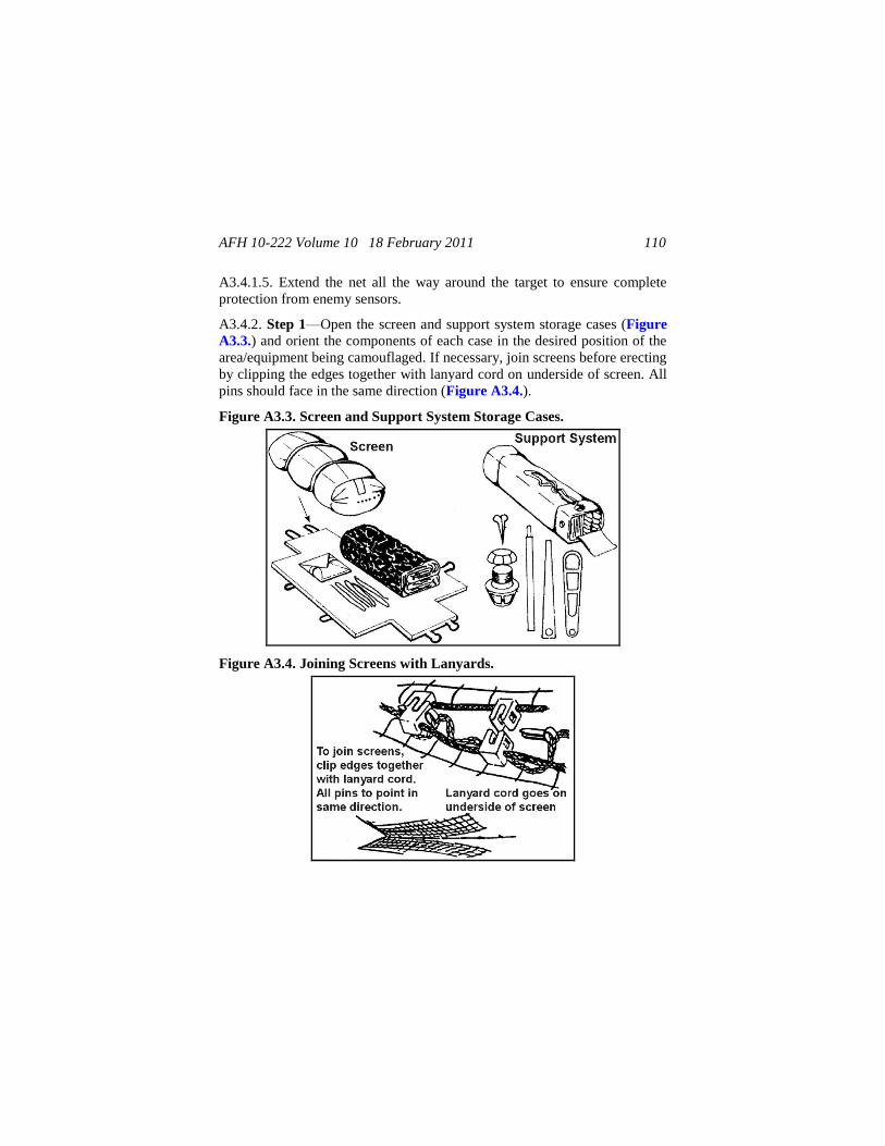
AFH 10-222 Volume 10 18 February 2011 110
A3.4.1.5. Extend the net all the way around the target to ensure complete
protection from enemy sensors.
A3.4.2. Step 1—Open the screen and support system storage cases (Figure
A3.3.) and orient the components of each case in the desired position of the
area/equipment being camouflaged. If necessary, join screens before erecting
by clipping the edges together with lanyard cord on underside of screen. All
pins should face in the same direction (Figure A3.4.).
Figure A3.3. Screen and Support System Storage Cases.
Figure A3.4. Joining Screens with Lanyards.
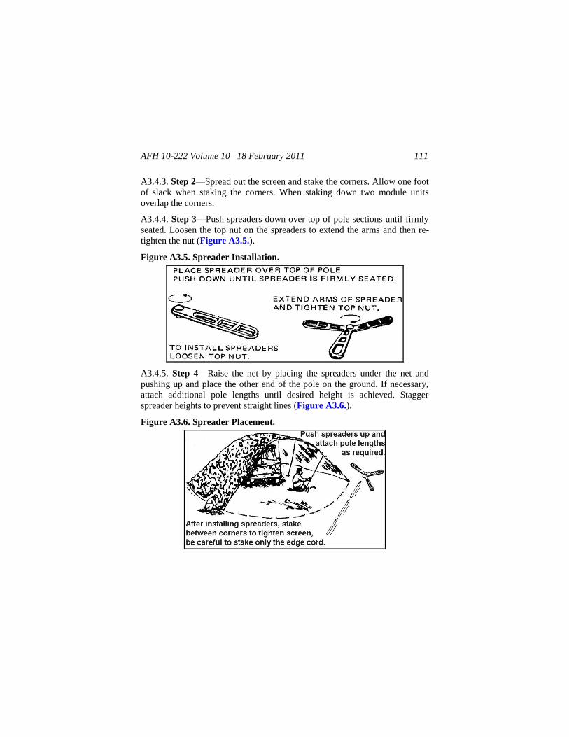
AFH 10-222 Volume 10 18 February 2011 111
A3.4.3. Step 2—Spread out the screen and stake the corners. Allow one foot
of slack when staking the corners. When staking down two module units
overlap the corners.
A3.4.4. Step 3—Push spreaders down over top of pole sections until firmly
seated. Loosen the top nut on the spreaders to extend the arms and then re-
tighten the nut (Figure A3.5.).
Figure A3.5. Spreader Installation.
A3.4.5. Step 4—Raise the net by placing the spreaders under the net and
pushing up and place the other end of the pole on the ground. If necessary,
attach additional pole lengths until desired height is achieved. Stagger
spreader heights to prevent straight lines (Figure A3.6.).
Figure A3.6. Spreader Placement.
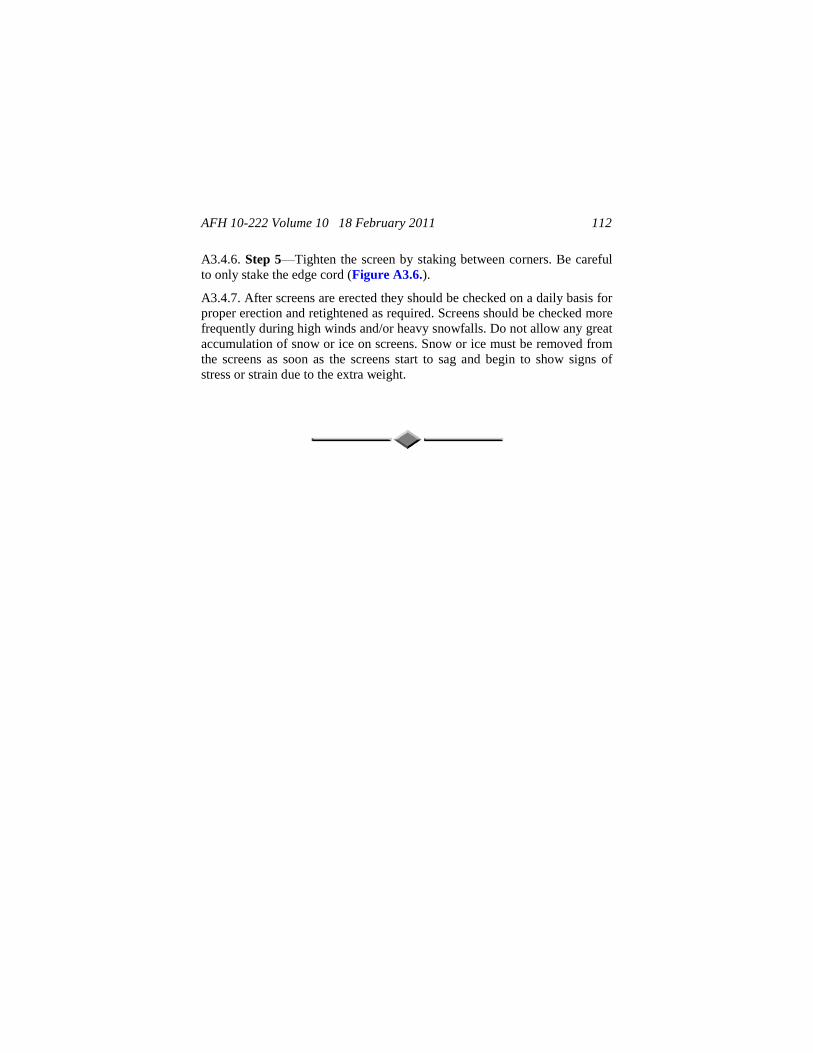
AFH 10-222 Volume 10 18 February 2011 112
A3.4.6. Step 5—Tighten the screen by staking between corners. Be careful
to only stake the edge cord (Figure A3.6.).
A3.4.7. After screens are erected they should be checked on a daily basis for
proper erection and retightened as required. Screens should be checked more
frequently during high winds and/or heavy snowfalls. Do not allow any great
accumulation of snow or ice on screens. Snow or ice must be removed from
the screens as soon as the screens start to sag and begin to show signs of
stress or strain due to the extra weight.