Embed Size (px)
Citation preview
I J C T A, 9(14) 2016, pp. 6433-6440© International Science Press
Accident Prevention System for Boats inMaritimeSimhadri Angadi and S. Manikandaswamy
ABSTRACT
Ultrasonic (US) and sonar (PIR) sensors are broadly used in mobile applications for distance measurements. In thisproject, an obstacle detection system is built based up on these two types of sensors. The system is intended for usethe elderly and people with vision impairment. The prototype developed has been tested to detect obstacles andshows accuracies of 95% to 99% for distance measurements if the sensor circuits are calibrated properly and theiroutput liberalized. The system also demonstrates good detection for different obstacle materials (e.g., wood, plastic,mirror, plywood and concretes) and colors. In this project the sonar ranging sensor senses the distance between thesearching object under the sea.
Keywords: Accident prevention, Boat, maritime, obstacle detection, sonar sensor, PIC microcontroller, vibration sensor.
I. INTRODUCTION
Ultrasonic (US) and Sonar (PIR) sensors are frequently used for mid-range distance measurements [1].Typical applications of these sensors include navigation (human, mobile robot and vehicles) as obstacleavoidance, distance measurement, counting devices (e.g., wait watcher, product assembly), surveillancesystem, object detection, edge detection and military applications. Robustness, lightweight, inexpensiveand fast response time makes these sensors suitable to be used in the development of navigation aids. Inaddition, the ability to gather information about the scene of action, localization, and mapping make theultrasonic sensor suitable in detecting the obstacles. Furthermore, a ultrasonic sensor can detect all types ofobstacle (e.g., wooden based object, metal concrete wall, plastics, rubber based product, transparent object,etc.) and it is not affected by poor lighting condition.
The sonar sensor was evaluated using three metrics: accuracy, robustness, and real-time performance[2]. The accuracy of the sonar sensor was evaluated by comparing the distances reported by the sensor withknown distances. The robustness of the sensor was evaluated by comparing the sensor’s accuracy underdifferent noise and reverberation conditions in different environments. Finally, the sensor’s real timeperformance was evaluated by measuring the time that it takes to process a signal and return a measurementwhen different optimizations are applied [3].
II. SYSTEM STRUCTURE AND METHODOLOGY
Basically, there are two main modules which include a control module that controls the communication ofdata and control over the channels, a microcontroller which is programmed to monitor and identify theobstacles and do necessary action, a sensor module which consists of all the sensors and a power module toprovide the required power. The main functioning is to identify the obstacle and gives the information tothe boat via Bluetooth in maritime and send the information to neighbor boat when the boat is damaged dueto any obstacles under the sea.
* Department of Electronics and Communication Engineering, SRM University, Kancheepuram, India, E-mail: [email protected];[email protected]

6434 Simhadri Angadi and S. Manikandaswamy
(A) Ultrasonic sensor
Ultrasonic sensors (HCSR04) are devices that use electrical to mechanical energy transformation to measuredistance from the sensor to the target object. Ultrasonic waves are longitudinal mechanical waves whichtravel as a sequence of compressions and rare factions along the direction of wave propagation through themedium [4].
These sensors are categorized in two types according to their working phenomenon piezoelectric sensorsand electrostatic sensors [5]. The ultrasonic sensor using the piezoelectric principle is in this project.Piezoelectric ultrasonic sensors use a piezoelectric material to generate the ultrasonic waves. Ultrasonicwaves are longitudinal mechanical waves which travel as a succession of compressions and rarefactionsalong the direction of wave propagation through the medium [6]. Any sound wave above the human auditoryrange of 20,000 Hz is called ultrasound.
Figure 2: Block Diagram of Receiver Section
Figure 1: Block Diagram of Transmitter Section
Accident Prevention System for Boats in Maritime 6435
(B) Sonar sensor (passive infrared)
A Passive Infrared sensor (HCS-R501), sensor) is an electronic device that measures infrared (IR) lightradiating from objects in field of view [7]. PIR sensors are often used in the construction of PIR-basedmotion detectors. Apparent motion is detected when an infrared source with temperature, such as a human,passes in front of an infrared source with another temperature, such as a wall.
All objects above absolute zero emit energy and is in reference is known as black body radiation. It isusually infrared radiation that is invisible to the human eye but can be detected by electronic devicesdesigned for that purpose. The term passive in this instance means that the PIR device does not emit aninfrared beam but passively accepts incoming infrared radiation [8]. “Infra” meaning below our ability todetect it visually, and “Red” because this color represents the lowest energy level that our eyes can sensebefore it becomes invisible. Thus, infrared means below the energy level of the colour red, and applies tomany sources of invisible energy.
(C) Vibration sensor
A piezoelectric sensor (ADIS16220) is a device that uses the piezoelectric effect to measure pressureacceleration, force by converting them in to a electrical signal. Piezoelectric sensors have proven to beversatile tools for the measurement of the various processes. They are used for quality assurance, processcontrol and for research and development in many different industries.
It has been successfully used in various applications, such as in medical, aerospace, nuclearinstrumentation, and as a pressure sensor in the touch pads of the mobile phones. In the automotive industry,piezoelectric elements are used to monitor the combustion when developing internal combustion engines.The sensors are either directly mounted into additional holes into the cylinder head or the spark/glow plugis equipped with a built in miniature piezoelectric sensor.
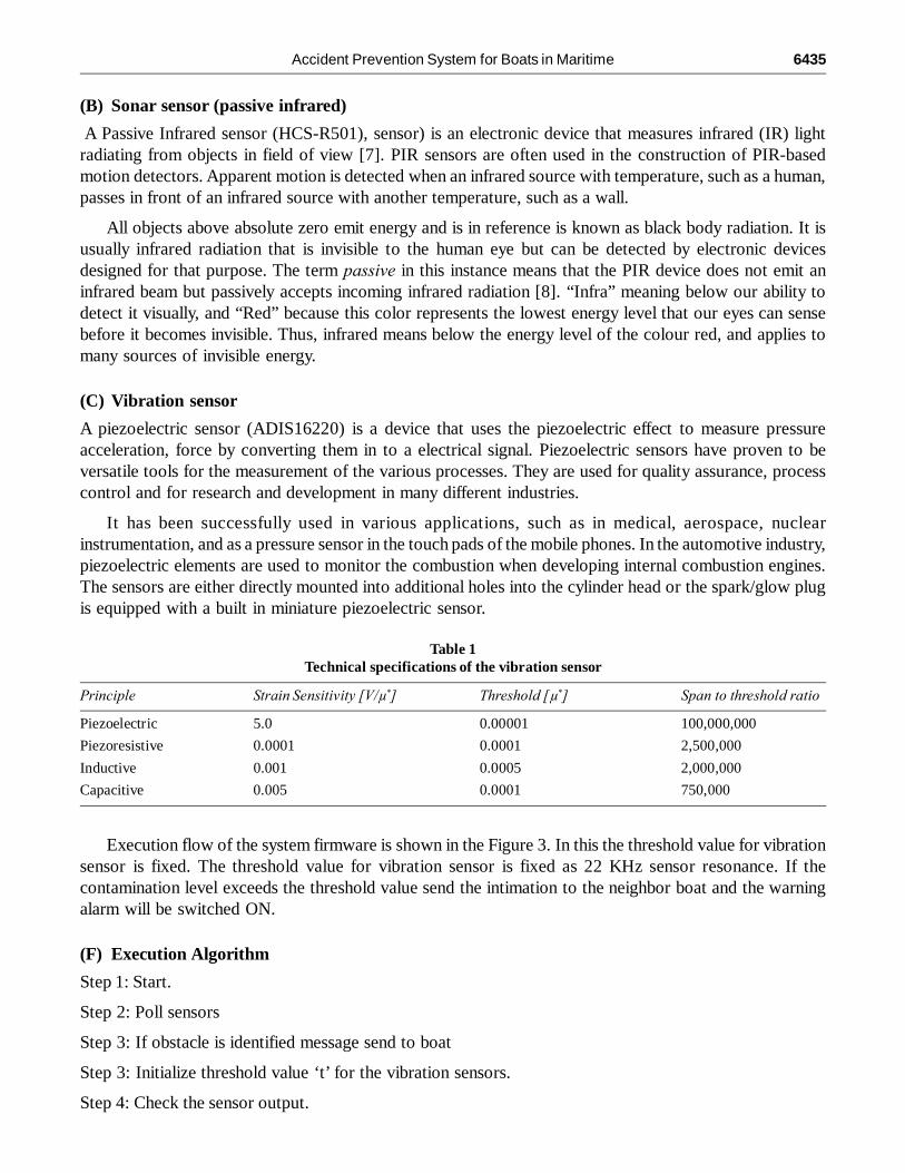
Table 1Technical specifications of the vibration sensor
Principle Strain Sensitivity [V/µ*] Threshold [µ*] Span to threshold ratio
Piezoelectric 5.0 0.00001 100,000,000
Piezoresistive 0.0001 0.0001 2,500,000
Inductive 0.001 0.0005 2,000,000
Capacitive 0.005 0.0001 750,000
Execution flow of the system firmware is shown in the Figure 3. In this the threshold value for vibrationsensor is fixed. The threshold value for vibration sensor is fixed as 22 KHz sensor resonance. If thecontamination level exceeds the threshold value send the intimation to the neighbor boat and the warningalarm will be switched ON.
(F) Execution Algorithm
Step 1: Start.
Step 2: Poll sensors
Step 3: If obstacle is identified message send to boat
Step 3: Initialize threshold value ‘t’ for the vibration sensors.
Step 4: Check the sensor output.

6436 Simhadri Angadi and S. Manikandaswamy
Step 5: If the sensor output is greater than‘t’ then alarm system will be ON
Step 6: Send the intimation to the neighbor boat while boat is damaged
Step7: stop
III. IMPLEMENTATION OF ACCIDENT PREVENTION SYSTEM
(A) Accident prevention system Implementation in Proteus environment
Accident prevention system is implemented in Proteus 8.1 ISIS environment at circuit level. The sensorcharacteristics are replaced with electrical equivalent using variable resistors. The control signal is indicatedby turning ON the LED. Firmware is loaded in 16f877a micro controller and simulated for various sensorsignal inputs.
Figure 3: Flow Chart of accident prevention system

Accident Prevention System for Boats in Maritime 6437
(B) Hardware Implementation
Hardware implementation of accident prevention system in maritime using various sensors which areinterfaced to PIC microcontroller for monitoring and identifying the obstacles under the water. Wheneverthe obstacle is identified it will give intimation to the boat. If damage is occurred the intimation send to theneighbor boat using zigbee.
IV. RESULTS AND DISCUSSION
(A) Proteus Simulation Result
Obstacle detection monitoring has been done in Proteus ISIS 8.1 software. This software does not supportfor a sensors, thus equivalent electrical output is provided by using variable resistor. Once simulation startsrun in first time, the LCD will displays text, ‘obstacle high or low’ and then reads the sensors and displaysthe values in their respective units. Shown in below figures.
Figure 5: Proteus output of receiver section
Figure 4: Proteus output of transmitter section

6438 Simhadri Angadi and S. Manikandaswamy
(B) Hardware Result
Here using sonar sensor (PIR sensor) identify the obstacles under the water and ultrasonic sensor identifiesthe obstacles surrounding the boat and send the message to the boat using Bluetooth. And then alarmsystem will be ON. In case of damage is occurred due to obstacles vibration sensor detected and zigbeeautomatically sends the intimation to the neighbor boat. Shown in the below figures.
Figure 6: Hardware output of transmitter section
Figure 7: Hardware output of receiver section

Accident Prevention System for Boats in Maritime 6439
Output of the bluetooth it will receives the message whenever the obstacles identified by the sensorsand displays the distance of the obstacle. Shown in the below figure.
Figure 8: Output of bluetooth
V. CONCLUSION
Accident prevention system for boats in maritime was developed. The system proposed in this paper notonly identifies the obstacles and it will take necessary action immediately. This system developed usingPIC microcontroller using various sensors like sonar (HCS-R501), ultrasonic sensor (HCSR04) and bydamage detection using vibration sensor (ADIS16220) and sends the intimation to the neighbor boat usingzigbee respectively are used in simulation implementation. Firmware is loaded in PIC16F877Amicrocontroller and this system is implemented in proteus environment. And in future we have to replacethe GSM instead of Bluetooth for fast communication. And GPS for locating the position of the boat.
ACKNOWLEDGMENTThe authors would like to thank the Department of Electronics and Communication Engineering at SRM University for providingthe facility and support to carry out this work.
REFERENCES[1] “Ultrasonic Sensors Performance in a Wireless Obstacle Detection System”, Baharuddin Mustapha1, Aladin Zayegh1,
Rezaul K. Begg2 College of Engineering & Science, Victoria University, Australia. Institute of Sport, Exercise and ActiveLiving (ISEAL) and College of Sport and Exercise Science (SES), Victoria University, Australia, 2013. IEEE DOI 10.1109/AIMS.89.
[2] “Software Based Sonar Ranging Sensor for Smart Phones”, Daniel Graham, George Simmons, David T.Nguyen, GangZhou Senior Member IEEE. DOI 10.1109/JIOT.2408451,2015
[3] B. Mustapha, A. Zayegh, R.K. Begg and A.H.A. Razak,” Design and Implementation of Wireless Obstacle DetectionSystem for Safe Locomotion”, Proceedings of Third International Conference on Intelligent Systems Modelling andSimulation, ISBN:978-0-7695 4668-1, Kota Kinabalu, Malaysia, 8-10 February 2012.
[4] B. Mustapha, A. Zayegh and R.K. Begg, “Multiple sensor-based Obstacle Detection System,” Proceedings of 4th InternationalConference on Intelligent and Advanced Systems, ISBN:978-1-4577-1966-0,Kuala Lumpur, 12-14 June 2012.
6440 Simhadri Angadi and S. Manikandaswamy
[5] Y. T. Win, N. Afzulpurkar, C. Punyasai and H. T. Htun, “Ultrasonic System Approach to Obstacle Detection and EdgeDetection,” Sensor & Transducers, ISSN 1726-5479, pp. 56-67, 2011.
[6] M. Fodor and O. Liska,”Design and Realization Sensorial Sys temon Detection Obstacle,” Proceedings of 8th IEEEInternational Symposium on Applied Machine Intelligence and Informatics; Herlany, Slovakia, January 28-30, 2010, pp.243–245, 2010.
[7] S. P. Tarzia, R. P. Dick, P. A. Dinda, and G. Memik, “Sonar-based measurement of user presence and attention,” inProceedings of the 11th international conference on Ubiquitous computing. ACM, 2009, pp. 89–92.
[8] H. Akbarally and L. Kleeman, “A sonar sensor for accurate 3d target localisation and classification,” in ICRA, 1995, pp.3003–3008.


![Accident Prevention[ Kalyani ].doc](https://img.pdfslide.us/doc/110x75/55cf8ff7550346703ba1d5df/accident-prevention-kalyani-doc.jpg)