Embed Size (px)
Citation preview

AC 2007-2870: DESIGN OF AN EXPERIMENTAL POWER SOURCE USINGHYDROGEN FUEL CELLS
Esther Ososanya, University of the District of Columbia
Samuel Lakeou, University of the District of Columbia
Abiyu Negede, University of the District of Columbia
Kidist Negede, University of the District of Columbia
Aziz Sirag, University of the District of Columbia
Sisay Beru, University of the District of Columbia
Azezom Meles, University of the District of Columbia
© American Society for Engineering Education, 2007

Design of an Experimental Power Source using Hydrogen Fuel Cells
Abstract
Proton Exchange Membrane (PEM) fuel cell is a device that converts electrochemical energy to electricity at high efficiency without combustion. The PEM fuel cell consists of an electrolyte membrane sandwiched between two electrodes (the anode- negative electrode and the cathode- the positive electrode). The electrodes are made of porous carbon plates which are laced with a catalyst_ a substance that accelerates chemical reactions. Hydrogen and oxygen are commonly used as the fuel and oxidant. At the anode, the hydrogen gas combines with the catalyst which causes the hydrogen to split into hydrogen ions and electrons. The electrons flow through an external circuit from the anode to the cathode producing an electrical current. The hydrogen ions flow through the membrane, and at the cathode, oxygen and hydrogen ions combine to form water, which flows out of the cell. The returning used electrons at the cathode side are recycled back to the anode, generating continuous electricity. Fuel cells can provide clean and efficient energy; low temperature operation; safe and quiet performance; ease of operation and low maintenance. In this study an experimental prototype fuel cell system is designed for undergraduate studies. In the presentation, an overview of fuel cells is provided starting with the fundamental principles, the different types, the key components, the basics of PEM fuel cell operation, the diverse benefits and the considerations of various applications.
Introduction
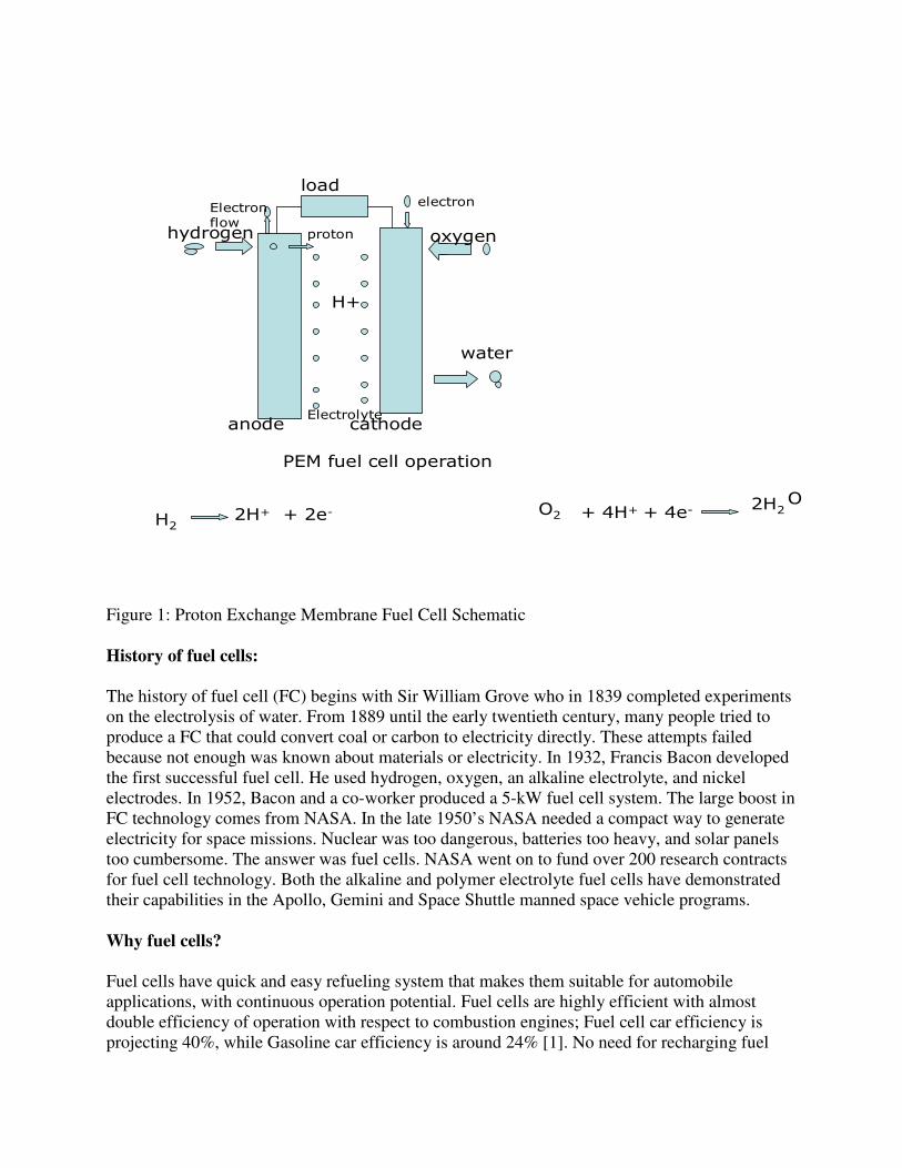
Fuel cell is an electrochemical energy conversion device. Depending on the type of electrolyte used fuel cells are classified. Of which our main emphasis would be on Proton Exchange Membrane (PEM) fuel cells as they have the highest power density and low operating temperature. The PEM fuel cell consists of an electrolyte membrane sandwiched between the anode and the cathode. The surrounding air provides enough oxygen concentration for the fuel cell and Hydrogen is produced from sun-light powered electrolysis of water. Other sources of hydrogen processes are Biological Water Splitting (green algae), Photoelectrochemical Water Splitting, Solar Thermal Water Splitting and others. The produced hydrogen can be stored in high pressure tanks in gaseous form, in liquid form or in Micropore Storage. Fuel cells are applicable for Stationary, Residential, Transportation and Portable Power, Landfill/wastewater treatment and most importantly the environmental-friendly energy production. The objectives of this study are: i) to exploit and advertise the benefits of fuel cell technology, ii) to compare and contrast different types of fuel cells, and iii) to build a prototype fuel cell generator and demonstrate its operation. Definition: A fuel cell is an electrochemical energy conversion device. A fuel cell converts the chemicals hydrogen and oxygen into water, and in the process it produces electricity, as shown in figure 1.
load
anode cathode
oxygenhydrogen
water
Electronflow
proton
electron
Electrolyte
PEM fuel cell operation
H+
H22H+ + 2e- O2 + 4H+ + 4e-
2H2O
Figure 1: Proton Exchange Membrane Fuel Cell Schematic History of fuel cells:
The history of fuel cell (FC) begins with Sir William Grove who in 1839 completed experiments on the electrolysis of water. From 1889 until the early twentieth century, many people tried to produce a FC that could convert coal or carbon to electricity directly. These attempts failed because not enough was known about materials or electricity. In 1932, Francis Bacon developed the first successful fuel cell. He used hydrogen, oxygen, an alkaline electrolyte, and nickel electrodes. In 1952, Bacon and a co-worker produced a 5-kW fuel cell system. The large boost in FC technology comes from NASA. In the late 1950’s NASA needed a compact way to generate electricity for space missions. Nuclear was too dangerous, batteries too heavy, and solar panels too cumbersome. The answer was fuel cells. NASA went on to fund over 200 research contracts for fuel cell technology. Both the alkaline and polymer electrolyte fuel cells have demonstrated their capabilities in the Apollo, Gemini and Space Shuttle manned space vehicle programs. Why fuel cells?
Fuel cells have quick and easy refueling system that makes them suitable for automobile applications, with continuous operation potential. Fuel cells are highly efficient with almost double efficiency of operation with respect to combustion engines; Fuel cell car efficiency is projecting 40%, while Gasoline car efficiency is around 24% [1]. No need for recharging fuel

cells, unlike batteries. Fuel cells are therefore ultimate substitute for gasoline -a major global warming problem both during production and use. Studies made by the U.S. Department of Energy [2] project that if 10% of automobiles used in the US were powered by fuel cells, currently regulated air pollutants would be cut by one million tons per year and 60 million tons of carbon dioxide would be eliminated from the yearly greenhouse gas production. Types of fuel cells:
The following sections compare and contrast different types of fuel cells, all of which have the same cell structure as in the illustrated schematic fuel cell in figure 1, except for the materials used and the electrochemical reactions. Each fuel cell type has its advantages and disadvantages. Proton Exchange Membrane (PEM) fuel cell
PEM delivers the most power density of all. It uses a solid polymer as an electrolyte and porous carbon electrodes which contains a platinum catalyst. The catalyst has to be CO poisoning sensitive. It also gets hydrogen from storage tanks or onboard reformers. PEM operates at low temperature up to 80oC, with less start –up time, and more durability. It is suitable for passenger vehicles.
The reactions, which take place in the PEM, are:
1. Anode: 2H2 => 4H+ + 4e-
2. Cathode: O2 + 4H+ + 4e- => 2H2O
3. Net reaction: 2H2 + O2 => 2H2O
Phosphoric Acid fuel cell
The electrolyte used is phosphoric acid. Electrodes are porous carbon electrodes containing a platinum catalyst. Efficiency of 85% for electricity and heat together has been reported, 37-42% for electricity alone. Phosphoric Acid FCs are large heavy and expensive, and thus suitable for stationary power generation only.
Alkaline fuel cell
The electrolyte used in the Alkaline fuel cell is solution of potassium hydroxide in water.
Electrodes are made of non-precious metals as a catalyst at the anode and cathode.
Very efficient, reaching efficiencies of 60 percent in space applications.
The disadvantage of this fuel cell type is that it is easily poisoned by carbon dioxide thus gases should be purified, which is an expensive process.
Direct Methanol fuel cell
• DMFC is powered by pure methanol, mixed with steam, in contrast to hydrogen.

• Store much energy in a small space, and uses small amount of power over a long period of time. DMFC is more suited to cell phones and laptops.
• The DMFC relies upon the oxidation of methanol on a catalyst layer to form carbon dioxide, with the following chemical reactions:
� Anode: CH3OH + H2O → CO2 + 6H+ + 6e-
� Cathode: 1.5O2 + 6H+ + 6e- → 3H2O
� Net reaction: CH3OH + 1.5O2 → CO2 + 2H2O
Molten Carbonate fuel cell
• MCFC type of fuel cells is developed for natural gas and coal-based power plants.
• Electrolyte composed of a molten carbonate salt mixture suspended in a porous LiAlO2.
• Can reach efficiencies approaching 60%. Up to 85% efficiency can be obtained when the waste heat is captured and used.
• High operating temperature (1,200ºF).
• MCFC uses internal reforming, non-precious metal as catalyst.
Advantages:
• Not prone to poisoning by oxides of carbon.
Solid-oxide fuel cell
• Best suited for large-scale stationary power generation.
• Operates at very high temperature 1832 °F.
• The steam as such could be channeled to turbines to produce more electricity, which improves overall efficiency from 50-60% to 70-80%.
• Most sulfur-resistant fuel cell and not poisoned by CO (carbon mono oxide).
• Slow startup and needs shielding to retain heat.
Disadvantage:
• Low durability.

Graphical fuel cell comparison:
0
200
400
600
800
1000
Phosphoric
Acid Fuel
Cell
Alkaline Fuel
Cell (AFC)
Molten
Carbonate
Fuel Cell
(MCFC
Solid Oxide
Fuel Cell
(SOFC)
Proton
Exchange
Membrane
Fuel Cell
(PEMFC)
Direct
Methanol
Fuel Cell
(DMFC)
Operating temprature
Series1
0%
10%
20%
30%
40%
50%
60%
70%
Phosphoric Acid
Fuel Cell
Alkaline Fuel Cell
(AFC)
Molten Carbonate
Fuel Cell (MCFC
Solid Oxide Fuel
Cell (SOFC)
Proton Exchange
Membrane Fuel
Cell (PEMFC)
Direct Methanol
Fuel Cell (DMFC)
Efficency
Series1
in degree Fahrenheit

Building and Testing of the prototype generator:

The above pictures show students in the lab building and testing a 10V hydrogen fuel cell, by stacking 10 1volt single fuel cell. The electrodes are made of graphite plates. The graphite plates are shaped and grooved to form channels for the air flow. With a 2 x 2 inches graphite plate, a voltage of approximately 1volt is generated across the pair of electrodes, with a small current in the milliamp range (approximately 5 mA) when operated at high pressure. The building of the 50mW prototype however costs $3.00/mW for the conducting materials. Increasing the surface area of the graphite electrode increases the current, and increasing the number of cells increase the voltage. The type of the electrolyte membrane used determines the efficiency, i.e., the rate in which the chemical reaction occurs. The study is still yet to determine the catalyst sensitivity to poison.
Hydrogen sources:
Efficient and low-cost production of pure hydrogen sources that does not pollute the cell catalysts are major issues in fuel cells application. Possible Hydrogen sources that are currently been researched include:
– Photoelectrochemical Water Splitting –Multi-junction Photovoltaic cells submerged in water with the presence of sun light. - Solar Thermal Water Splitting -highly concentrated sunlight can be used to
generate the high temperatures needed to split methane into hydrogen and carbon.
– Solar Powered Electrolysis of water Work is currently in progress to power the electrolysis of water used in this project by a 1.8 KW site Solar/Wind Combo generator, to minimize the cost of hydrogen production. Fuel Cell applications:
� Stationary – In large-scale building systems, fuel cells can reduce facility energy service
costs by 20% to 40% over conventional energy service. � Residential
– can be used to provide hot water or space heating for a home. � Transportation
– can be used in automobiles, buses, locomotives, airplanes, scooters and golf carts.
� Portable Power – will help consumers talk for up to a month on a cellular phone without
recharging. – can be used to power pagers, video recorders, portable power tools, and
low power remote devices such as hearing aids, smoke detectors, burglar alarms, hotel locks and meter readers.
Fuel-cell benefits:
� Energy Security

– Research shows that if just 20% of cars used fuel cells, we could cut oil imports by 1.5 million barrels every day [3].
� High Reliability – U.S. businesses lose $29 billion annually from computer failures due to
power outages. Fuel cells may help prevent both loss of power and loss of money.
� Fuel Flexibility – The hydrogen as energy source for the fuel cell can be obtained from
various fuel sources like hydrocarbon, alcohol fuel, ammonia, borohydride, or even from water.
� High Efficiency
– Fuel cell power generation systems in operation today achieve 40% to 50% fuel-to-electricity efficiency utilizing hydrocarbon fuels. – In combination with a turbine, electrical efficiencies can exceed 60%. – When waste heat is put to use for heating and cooling, fuel utilization can exceed 85%. – Fuel cell passenger vehicles are expected to be up to three times more efficient than internal combustion engines, which now operate at 10 to 16% efficiency.
� Environmental Benefit – Fuel cells can reduce pollution today and offer the promise of eliminating
pollution tomorrow. � Motor Vehicles – Fuel cell vehicles operating on hydrogen stored on-board the vehicles
produce zero pollution in the conventional sense. The only byproducts are water and heat.
� Modularity/Scalability/Flexible Sitting – Since they are scalable, fuel cells can be stacked until the desired power
output is reached which means no need of using step-up or step-down transformers.
� Battery replacement/alternative – Fuel cell, for portable electronic devices, would provide a much longer operating life than a battery would, in a package of lighter or equal weight per unit of power output.
Conclusion and Future work:
The benefits of fuel cells are undeniable, but more work is required to find improved and less expensive conducting materials at low cost, and research study that will address the key challenges in fuel cells efficiency, durability, and power density. References:
1. Direct Hydrogen-Fueled Proton-Exchange-Membrane Fuel Cell System for Transportation Applications: Conceptual Vehicle Design Report, Ford Motor Company. Publisher: Technology Books (B/T Books), July 1997, ISBN-13: 978-0899343525

2. U. S. Department of Energy, Energy Efficiency and Renewable energy, Hydrogen Codes, Standards, and Safety, Neil P. Rossmeissl, 2006.
3. Srinivasan et. Al. “Fuel Cells: Reaching the Era of Clean and Efficient Power Generation in the Twenty-First Century.” Annu. Rev. Energy Environment, 1999, 24:281-328