Embed Size (px)
Citation preview
General rights Copyright and moral rights for the publications made accessible in the public portal are retained by the authors and/or other copyright owners and it is a condition of accessing publications that users recognise and abide by the legal requirements associated with these rights.
Users may download and print one copy of any publication from the public portal for the purpose of private study or research.
You may not further distribute the material or use it for any profit-making activity or commercial gain
You may freely distribute the URL identifying the publication in the public portal If you believe that this document breaches copyright please contact us providing details, and we will remove access to the work immediately and investigate your claim.
Downloaded from orbit.dtu.dk on: Jan 16, 2022
Experimental performance analysis of a multiple-source and multiple-use heat pumpsystem: Winter field experiment and heating operation performance evaluation
Liu, Mingzhe; Ooka, Ryozo; Hino, Toshiyuki; Wen, Ke; Choi, Wonjun; Lee, Doyun; Ikeda, Shintaro;Palasz, Djafar Reza
Published in:E3S Web of Conferences
Link to article, DOI:10.1051/e3sconf/201911101076
Publication date:2019
Document VersionPublisher's PDF, also known as Version of record
Link back to DTU Orbit
Citation (APA):Liu, M., Ooka, R., Hino, T., Wen, K., Choi, W., Lee, D., Ikeda, S., & Palasz, D. R. (2019). Experimentalperformance analysis of a multiple-source and multiple-use heat pump system: Winter field experiment andheating operation performance evaluation. E3S Web of Conferences, 111, [01076].https://doi.org/10.1051/e3sconf/201911101076
* Corresponding author: [email protected]
Experimental performance analysis of a multiple-source and multiple-use heat pump system: winter field experiment and heating operation performance evaluation
Mingzhe Liu1*, Ryozo Ooka2, Toshiyuki Hino2, Ke Wen1, Wonjun Choi2, Doyun Lee1, Shintaro Ikeda3, and Djafar Reza Palasz4 1Graduate School of Engineering, The University of Tokyo, 4-6-1 Komaba, Meguro-ku, Tokyo 153-8505, Japan 2Institute of Industrial Science, University of Tokyo, 4-6-1, Komaba, Meguro-ku, Tokyo 153-8505, Japan 3Tokyo University of Science, 6-3-1, Niijuku, Katsushika-ku, Tokyo 125-8585, Japan 4Technical University of Denmark, Anker Engelunds Vej 1 Bygning 101A, 2800 Kgs. Lyngby, Denmark
Abstract. We herein report the development of a distributed heat pump system that can utilize a variety of renewable energy sources to meet different building heating and cooling demands (i.e., a multiple source and multiple use heat pump system, MMHP). In this system, a water circulating loop is used to connect ground heat exchangers, a unique sky-source heat pump, and various heat pumps for heating and cooling purposes to form a thermal network within a building. This distribution increases the flexibility of the system and allows an improved matching of supply and demand. To evaluate the system performance, an experimental house was constructed, and a winter field experiment was conducted. We found that the reported heat pump for floor heating achieved a stable operation with a high coefficient of performance of ~11.5, while the heat collecting operation performance of the sky-source heat pump varied significantly depending on the amount of solar radiation and the outside air temperature. Finally, since the sky-source heat pump contributes to an improvement in the whole system performance, it appears that there is still room for improved regarding the whole system performance by adjusting the operating and control strategy.
1 Introduction The energy input for building operations is mainly composed of fossil fuel-based energy carriers, and therefore accounts for a large proportion of global greenhouse gas emissions (~25% of the total worldwide emissions) [1]. Although the exact quantity varies by country and region, energy use in buildings is thought to constitute 35–40% of global energy usage [2,3]. Thus, to decrease the energy demand and its related emissions, significant effort has been focused on boosting renewable energies in building heating and cooling. The development of heat pump (HP) technologies has made it possible to use a variety of renewable energy sources as heating and cooling sources for buildings such as solar energy, geothermal energy and so on. To meet the thermal and cooling loads of buildings, the use of renewable energy that is available close to the buildings has also been investigated using various types of heat pump systems [4–11]. For example, the so-called solar-assisted ground source heat pump system (SAGSHPS), which can couple geothermal and solar thermal energies, has been proposed and its feasibility and performance have been examined. Ozgener et al. carried out an experimental performance study of a SAGSHPS for greenhouse heating, and exergoeconomic analysis was also conducted to evaluate its feasibility [12,13].
Furthermore, through experiments conducted in winter, an experimental study on the influence of operation modes on the heating performance of a SAGSHPS were performed by Dai et al. [14]. They found that solar thermal energy could be used to accelerate soil recovery when the heat pump unit was turned off, and the solar heat storage water tank was found to be beneficial to the stable operation of the SAGSHPS. The conventional heat pump systems proposed in past researches commonly employ either one or two renewable energy sources that can complement one another to meet the cooling and heating demands of a building. Although this kind of system aids in reducing the building’s energy consumption, it has a limited capacity due to the use of limited renewable energy resources. Furthermore, each renewable energy source has its own advantages and disadvantages; for example, solar radiation is a type of flow energy and is quantitatively limitless, but its availability is intermittent. In addition, geothermal energy is a stable stocked energy source, but is quantitatively finite. The combination of various energy sources has therefore been proposed and practiced to account for their individual shortcomings [15]. To achieve a higher efficiency than conventional systems, we proposed a multiple source and multiple use heat pump (MMHP) system. In the MMHP system,
, 0 (201Web of Conferences https://doi.org/10.1051/e3sconf/20191110109)201
E3S 111 10CLIMA 9
76 76
© The Authors, published by EDP Sciences. This is an open access article distributed under the terms of the Creative Commons Attribution License 4.0 (http://creativecommons.org/licenses/by/4.0/).
multiple heat sources such as solar heat, geothermal heat and air source are utilized and multiple thermal uses such as cooling, heating and domestic how water supply are used in the light of heat source temperature. According to the above introduction, we herein report the development of the MMHP system that can utilize a variety of renewable energy sources surrounding a building [16]. This system is a hydronic heating and cooling system, which connects ground heat exchangers, a unique sky-source heat pump, and various heat pumps by a water circulating loop for heating and cooling purposes, to ultimately form a thermal network within a building. To evaluate the performance of this system, an experimental house is constructed, and field experiments are conducted in winter to confirm the performance of this system.
2 MMHP system overview
2.1 System concept
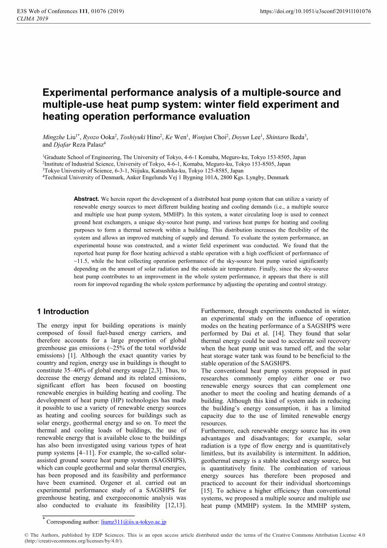
Figure 1 shows the configuration of the described system in addition to the thermal flow directions of the various components. More specifically, this MMHP system consists of a water loop that exchanges heat with a sky-source heat pump (SSHP), ground-source heat pumps for various heating and cooling services, and ground heat exchangers (GHEs) [16]. A water circulating loop is used to connect each component to form a thermal network within the building. This distribution increases the flexibility of the system and allows improved matching of supply and demand. In the MMHP system, the water temperature in the circulating loop is maintained within a certain range due to the natural ground temperature (e.g., ~17 ºC in the case of the Tokyo area), and this temperature range enables high coefficients of performance (COPs) in both the heating and cooling cycles of each HP. When the HP operates in a heating cycle, the loop water temperature is reduced, while this temperature increases when the HP operates in a cooling cycle. The resulting temperature deviation will be absorbed by the ground. When this exceeds a certain limit (e.g., 5 ºC), the SSHP works as either a collector or a radiator to heat or cool the circulating water within the loop. Figure 2 shows the cross-section of sky-source outdoor panel, which can function as either an evaporator or a condenser depending on the operating mode. The outdoor panel of the SSHP is composed of aluminum finned tubes placed in parallel. It functions as a solar collector and can absorb both solar heat and heat from the surrounding air by evaporation of the panel refrigerant [16]. The collector temperature is close to that of the surrounding air when sufficient solar radiation is available. As insolation decreases, the collector temperature becomes lower than that of the surrounding air, and the panel absorbs both solar heat and heat from the air.
Fig. 1. System concept.
Fig. 2. Cross-section of the sky-source outdoor panel.
On cloudy days and at night, insufficient solar heat is available for collection, and so the refrigerant evaporation temperature may drop further, and the SSHP panel can collect heat from the air through natural drafts and wind, thereby functioning as an air-source heat pump. Although panel frosting can occur, defrosting is unnecessary [15]. This panel can also function as a nocturnal radiator by condensing a gaseous refrigerant and dissipating heat through nocturnal radiation and natural drafts during the night (this is more common in summer). In the event of rain, the evaporation of rainwater from the panel can also aid in removing heat from the panel. Photovoltaic cells are also attached to the outdoor panel. Furthermore, we note that it is possible to provide waste heat recovery and adjust the demand time divergence between heat and cold demand using underground thermal energy storage through the water loop, where the quantitative unbalance is cleared by the SSHP.
2.2 Composition of the experimental building
To verify the described concept and to confirm the energy efficiency of the MMHP system, we prepared the necessary prototype equipment in an experimental building named the “RE House” on the University of Tokyo Kashiwa campus (Kashiwa-shi, Chiba-ken, Japan). As shown in Figs. 3 and 4, the MMHP system in the RE house is a distributed hydronic heating and cooling system, which connects three double helix
, 0 (201Web of Conferences https://doi.org/10.1051/e3sconf/20191110109)201
E3S 111 10CLIMA 9
76 76
2
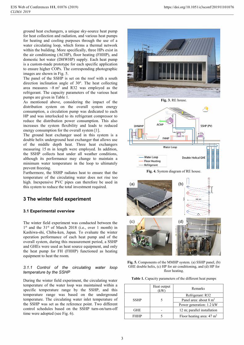
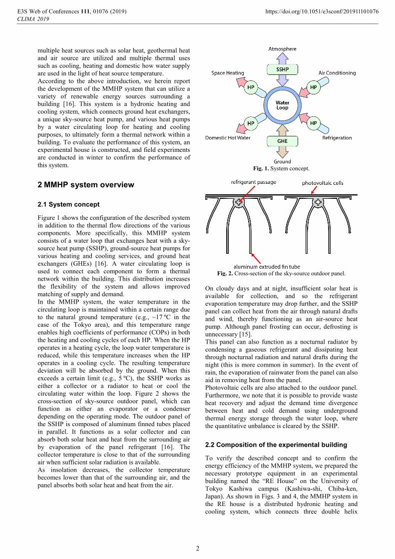
ground heat exchangers, a unique sky-source heat pump for heat collection and radiation, and various heat pumps for heating and cooling purposes through the use of a water circulating loop, which forms a thermal network within the building. More specifically, three HPs exist in the air conditioning (ACHP), floor heating (FHHP), and domestic hot water (DHWHP) supply. Each heat pump is a custom-made prototype for each specific application to ensure higher COPs. The corresponding photographic images are shown in Fig. 5. The panel of the SSHP is set on the roof with a south direction inclination angle of 30°. The heat collecting area measures ~8 m2 and R32 was employed as the refrigerant. The capacity parameters of the various heat pumps are given in Table 1. As mentioned above, considering the impact of the distribution system on the overall system energy consumption, a circulation pump was dedicated to each HP and was interlocked to its refrigerant compressor to reduce the distribution power consumption. This also increases the system flexibility and leads to reduced energy consumption for the overall system [1]. The ground heat exchanger used in this system is a double helix underground heat exchanger that allows use of the middle depth heat. Three heat exchangers measuring 15 m in length were employed. In addition, the SSHP collects heat under all weather conditions, although its performance may change to maintain a minimum water temperature in the loop to ultimately prevent freezing. Furthermore, the SSHP radiates heat to ensure that the temperature of the circulating water does not rise too high. Inexpensive PVC pipes can therefore be used in this system to reduce the total investment required.
3 The winter field experiment
3.1 Experimental overview
The winter field experiment was conducted between the 1st and the 31st of March 2018 (i.e., over 1 month) in Kashiwa-shi, Chiba-ken, Japan. To evaluate the winter operation performance of each heat pump and of the overall system, during this measurement period, a SSHP and GHEs were used as heat source equipment, and only the heat pump for FH (FHHP) functioned as heating equipment to heat the room.
3.1.1 Control of the circulating water loop temperature by the SSHP
During the winter field experiment, the circulating water temperature of the water loop was maintained within a specific temperature range by the SSHP, and this temperature range was based on the underground temperature. The circulating water inlet temperature of the SSHP was set as the reference point. Two different control schedules based on the SSHP turn-on/turn-off time were adopted (see Fig. 6).
Fig. 3. RE house.
Fig. 4. System diagram of RE house.
(a)
(c) (d)
(b)
Fig. 5. Components of the MMHP system. (a) SSHP panel, (b) GHE double helix, (c) HP for air conditioning, and (d) HP for
floor heating.
Table 1. Capacity parameters of the different heat pumps
Heat output (kW) Remarks
SSHP 5 Refrigerant: R32
Panel area: about 8 m2
Power generation: 1.2 kW GHE - 12 m; parallel installation
FHHP 5 Floor heating area: 47 m2
, 0 (201Web of Conferences https://doi.org/10.1051/e3sconf/20191110109)201
E3S 111 10CLIMA 9
76 76
3
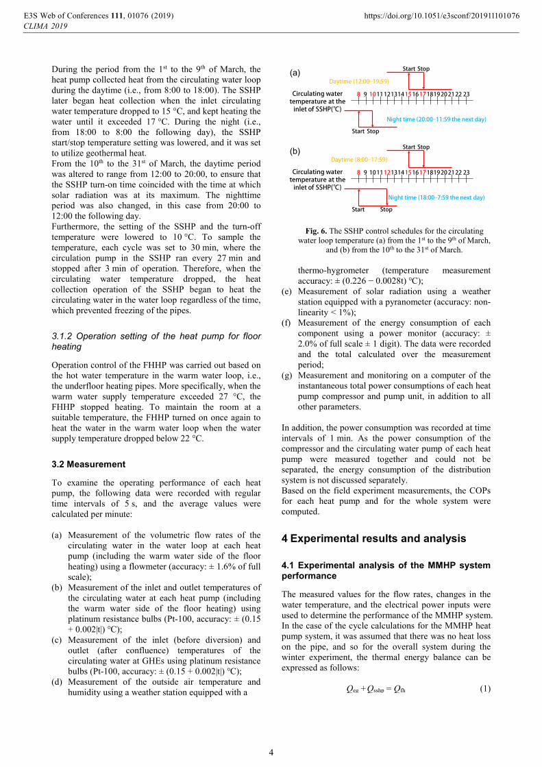
During the period from the 1st to the 9th of March, the heat pump collected heat from the circulating water loop during the daytime (i.e., from 8:00 to 18:00). The SSHP later began heat collection when the inlet circulating water temperature dropped to 15 °C, and kept heating the water until it exceeded 17 °C. During the night (i.e., from 18:00 to 8:00 the following day), the SSHP start/stop temperature setting was lowered, and it was set to utilize geothermal heat. From the 10th to the 31st of March, the daytime period was altered to range from 12:00 to 20:00, to ensure that the SSHP turn-on time coincided with the time at which solar radiation was at its maximum. The nighttime period was also changed, in this case from 20:00 to 12:00 the following day. Furthermore, the setting of the SSHP and the turn-off temperature were lowered to 10 °C. To sample the temperature, each cycle was set to 30 min, where the circulation pump in the SSHP ran every 27 min and stopped after 3 min of operation. Therefore, when the circulating water temperature dropped, the heat collection operation of the SSHP began to heat the circulating water in the water loop regardless of the time, which prevented freezing of the pipes.
3.1.2 Operation setting of the heat pump for floor heating
Operation control of the FHHP was carried out based on the hot water temperature in the warm water loop, i.e., the underfloor heating pipes. More specifically, when the warm water supply temperature exceeded 27 °C, the FHHP stopped heating. To maintain the room at a suitable temperature, the FHHP turned on once again to heat the water in the warm water loop when the water supply temperature dropped below 22 °C.
3.2 Measurement
To examine the operating performance of each heat pump, the following data were recorded with regular time intervals of 5 s, and the average values were calculated per minute: (a) Measurement of the volumetric flow rates of the
circulating water in the water loop at each heat pump (including the warm water side of the floor heating) using a flowmeter (accuracy: ± 1.6% of full scale);
(b) Measurement of the inlet and outlet temperatures of the circulating water at each heat pump (including the warm water side of the floor heating) using platinum resistance bulbs (Pt-100, accuracy: ± (0.15 + 0.002|t|) ℃);
(c) Measurement of the inlet (before diversion) and outlet (after confluence) temperatures of the circulating water at GHEs using platinum resistance bulbs (Pt-100, accuracy: ± (0.15 + 0.002|t|) ℃);
(d) Measurement of the outside air temperature and humidity using a weather station equipped with a
Stop
Circulating water temperature at the
inlet of SSHP(℃)
8 9 1011 121314 15 16 17 1819 20 21 22 23
Daytime (12:00‒19:59)
Night time (20:00‒11:59 the next day)
Start
StopStart
Stop
Circulating water temperature at the
inlet of SSHP(℃)
8 9 1011 121314 15 16 17 1819 20 21 22 23
Daytime (8:00‒17:59)
Night time (18:00‒7:59 the next day)
Start
StopStart
(a)
(b)
Fig. 6. The SSHP control schedules for the circulating water loop temperature (a) from the 1st to the 9th of March,
and (b) from the 10th to the 31st of March. thermo-hygrometer (temperature measurement accuracy: ± (0.226 − 0.0028t) ℃);
(e) Measurement of solar radiation using a weather station equipped with a pyranometer (accuracy: non-linearity < 1%);
(f) Measurement of the energy consumption of each component using a power monitor (accuracy: ± 2.0% of full scale ± 1 digit). The data were recorded and the total calculated over the measurement period;
(g) Measurement and monitoring on a computer of the instantaneous total power consumptions of each heat pump compressor and pump unit, in addition to all other parameters.
In addition, the power consumption was recorded at time intervals of 1 min. As the power consumption of the compressor and the circulating water pump of each heat pump were measured together and could not be separated, the energy consumption of the distribution system is not discussed separately. Based on the field experiment measurements, the COPs for each heat pump and for the whole system were computed.
4 Experimental results and analysis
4.1 Experimental analysis of the MMHP system performance
The measured values for the flow rates, changes in the water temperature, and the electrical power inputs were used to determine the performance of the MMHP system. In the case of the cycle calculations for the MMHP heat pump system, it was assumed that there was no heat loss on the pipe, and so for the overall system during the winter experiment, the thermal energy balance can be expressed as follows:
Qeg +Qsshp = Qfh (1)
, 0 (201Web of Conferences https://doi.org/10.1051/e3sconf/20191110109)201
E3S 111 10CLIMA 9
76 76
4

Where, Qeg is the heat extracted from the ground, Qsshp is the heat transferred into the water loop by the SSHP, Qfh is the heat rejected to the floor heating room. The heat rejected to the floor heating room, Qfh is calculated from the following equation:
Qfh = ρ×cw×Vwl× (Twl, out−Twl, in) (2)
The heat output of the SSHP Qsshp, which is the heat transferred into the water loop by the SSHP, can be calculated as follows:
Qsshp =ρ×cw×Vsshp× (Tsshp, out−Tsshp, in) (3)
According to equation (1), the heat extracted from the ground Qeg can be calculated from the following equation:
Qeg = Qfh−Qsshp (4)
Thus, for the MMHP system, the COP of the heat pump unit (SSHP : COPsshp , FHHP : COPfh) and for the whole heat pump system (COPsys) can be defined as follows:
COPsshp = Qsshp/Wsshp (5)
COPfh = Qfh/Wfh (6)
COPsys = Qfh/(Wfh+Wsshp) (7) where, Vwl and Vsshp are the volumetric flow rates, ρ is the density of water, cw is the specific heat capacity of water, and Wfh and Wsshp are the power consumptions of the heat pump unit, which includes the power input to the compressor, the circulation pump, and the automatic control system.
4.2 Results and discussion
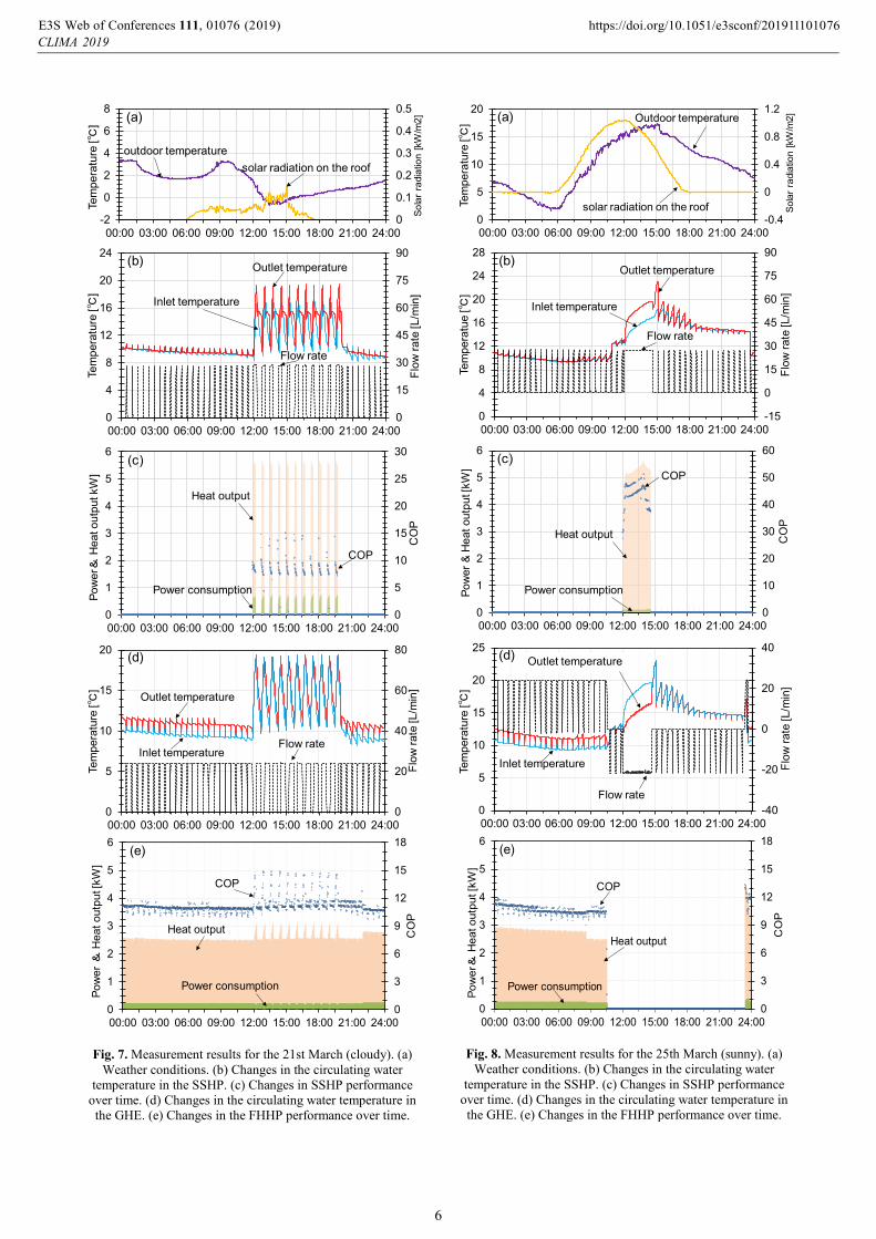
Based on the quantity of solar radiation and the outside air temperature, the optimal day (25th March, 2018) and the most unsuitable day (21st March, 2018) for SSHP heat collection were taken as examples to study the winter operating performance of the MMHP system.
4.2.1 Cloudy day results (21st March)
Figure 7 shows the measurement results obtained on the 21st of March. From 20:00 to 12:00 the following day, the GHEs extracted heat from the ground and supplied heat to the FHHP unit. Between 12:00 and 20:00, the SSHP maintained the temperature of the circulating water between 15–17 °C. In addition, the heat load increased because of a low outdoor temperature. Therefore, the FHHP maintained a continuous operation, and the majority of heat generated by the SSHP was used for FH, with no recovery of the soil temperature being achieved by the SSHP. Furthermore, as it was cloudy day and both the quantity
of solar radiation and the outside temperature were reduced, a lower average COP of 8.3 was obtained for the SSHP. The result of the FHHP is shown in Fig. 7(e). As mentioned previously, the FHHP maintained a continuous operation due to the high heat load. Although the FHHP can maintain a stable operation with a COP of ~11, fluctuation in the COP due to the temperature rise of the circulating water was observed. As the performance of the FHHP increases as the temperature of the circulating water increases, it appears that there is still room for improvement in the performance by adjusting the operation conditions.
4.2.2 Sunny day results (25th March)
Figure 8 shows the measurement results obtained on the 25th of March. Between 0:00 and 12:00, and from 15:00 to 24:00, the SSHP stopped, but the GHEs extracted heat from the ground, and supplied heat to the FHHP to heat the room. From 12:00 to 15:00, the SSHP gathered heat from both solar radiation and from the atmosphere. During the stable operation, the SSHP maintained a heat output of ~5 kW. From the beginning of the operation, the COP of the SSHP continued to rise with an increase in the quantity of solar radiation and with an increase in the outside air temperature, giving a maximum COP of ~50 during this period. However, when less solar radiation was available, the COP of the SSHP dropped, and an average COP of 42.9 was obtained for the overall heat collection operation. As shown in Figs. 8(c) and 8(d), the heat generated by the SSHP was used to heat the ground through the GHEs, which can recover the decrease in the soil temperature due to heat extraction for floor heating. In addition, Fig. 8(e) shows the changes in the FHHP performance over time. In this case, the COP remained relatively constant in the stable period from 23:30 to 10:30 the following day. The observed fluctuation in the COP every 30 min is due to the temperature change caused by switching on of the SSHP circulation pump, which is set to sample the water temperature.
4.2.3 Discussion
The results obtained from the winter field experiment over the heating period between the 1st and the 31st of March were evaluated to determine the performance characteristics of the reported MMHP system. Based on the accumulated value of heat output and power consumption over March, we calculated average COP of each heat pump and whole system. Figures 9 and 10 show the heat output, power consumption, and power generation for the two representative days and for the whole experimental period, respectively. The COP values of the various heat pumps and for the whole system are given in Table 2. In the case of a sunny day (i.e., 25th March), the average COPsys was 9.6, and the power generation by the photovoltaic cell on SSHP panel was 8.0 kWh, which exceeded the power consumption of whole system. However, due to the
, 0 (201Web of Conferences https://doi.org/10.1051/e3sconf/20191110109)201
E3S 111 10CLIMA 9
76 76
5
0
0.1
0.2
0.3
0.4
0.5
-2
0
2
4
6
8
00:00 03:00 06:00 09:00 12:00 15:00 18:00 21:00 24:00
Sola
r ra
diat
ion
[kW
/m2]
Tem
pera
ture
[℃]
outdoor temperaturesolar radiation on the roof
(a)
0
15
30
45
60
75
90
0
4
8
12
16
20
24
00:00 03:00 06:00 09:00 12:00 15:00 18:00 21:00 24:00Fl
ow ra
te[L
/min
]
Tem
pera
ture
[℃]
Inlet temperature
Outlet temperature
Flow rate
(b)
0
5
10
15
20
25
30
0
1
2
3
4
5
6
00:00 03:00 06:00 09:00 12:00 15:00 18:00 21:00 24:00
CO
P
Pow
er&
Hea
t out
put k
W]
Heat output
Power consumption
COP
(c)
0
20
40
60
80
0
5
10
15
20
00:00 03:00 06:00 09:00 12:00 15:00 18:00 21:00 24:00
Flow
rate
[L/m
in]
Tem
pera
ture
[℃]
Outlet temperature
Inlet temperatureFlow rate
(d)
0
3
6
9
12
15
18
0
1
2
3
4
5
6
00:00 03:00 06:00 09:00 12:00 15:00 18:00 21:00 24:00
CO
P
Pow
er &
Hea
t out
put [
kW]
Heat output
Power consumption
COP
(e)
Fig. 7. Measurement results for the 21st March (cloudy). (a) Weather conditions. (b) Changes in the circulating water
temperature in the SSHP. (c) Changes in SSHP performance over time. (d) Changes in the circulating water temperature in the GHE. (e) Changes in the FHHP performance over time.
-0.4
0
0.4
0.8
1.2
0
5
10
15
20
00:00 03:00 06:00 09:00 12:00 15:00 18:00 21:00 24:00
Sola
r ra
diat
ion
[kW
/m2]
Tem
pera
ture
[℃] Outdoor temperature
solar radiation on the roof
(a)
-15
0
15
30
45
60
75
90
0
4
8
12
16
20
24
28
00:00 03:00 06:00 09:00 12:00 15:00 18:00 21:00 24:00
Flow
rate
[L/m
in]
Tem
pera
tue
[℃]
Inlet temperature
Outlet temperature
Flow rate
(b)
0
10
20
30
40
50
60
0
1
2
3
4
5
6
00:00 03:00 06:00 09:00 12:00 15:00 18:00 21:00 24:00
CO
P
Pow
er &
Hea
t out
put [
kW]
Heat output
Power consumption
COP(c)
-40
-20
0
20
40
0
5
10
15
20
25
00:00 03:00 06:00 09:00 12:00 15:00 18:00 21:00 24:00
Flow
rate
[L/m
in]
Tem
pera
ture
[℃]
Outlet temperature
Inlet temperature
Flow rate
(d)
0
3
6
9
12
15
18
0
1
2
3
4
5
6
00:00 03:00 06:00 09:00 12:00 15:00 18:00 21:00 24:00
CO
P
Pow
er&
Hea
t out
put [
kW]
Heat output
Power consumption
COP
(e)
Fig. 8. Measurement results for the 25th March (sunny). (a) Weather conditions. (b) Changes in the circulating water
temperature in the SSHP. (c) Changes in SSHP performance over time. (d) Changes in the circulating water temperature in the GHE. (e) Changes in the FHHP performance over time.
, 0 (201Web of Conferences https://doi.org/10.1051/e3sconf/20191110109)201
E3S 111 10CLIMA 9
76 76
6

decreased solar radiation and lower outside temperature on the cloudy day (i.e., 21st March) the average COPsys was 8.2, and the SSHP efficiency was reduced. Moreover, although the heat output of the SSHP was higher than that of geothermal heat on the two representative days, the SSHP and the geothermal heat accounted for similar proportions of the heat output from the overall system when considering the complete winter computed.
5 Conclusion We herein reported the development of a distributed heat pump system that can utilize a variety of renewable energy sources to meet different building heating and cooling demands. To evaluate the system performance, an experimental house was constructed, and a winter field experiment was carried out under different weather conditions in Chiba, Japan. Based on a comparative experimental analysis of the performance of the multiple source and multiple use heat pump (MMHP) system under different weather conditions, several conclusions were reached. Firstly, the custom-made heat pump for floor heating (FHHP) maintained a stable operation with a coefficient of performance (COP) of ~11.5 during the heating period. However, the performance of the FHHP increased as the temperature of the circulating water increased, and so it is apparent that there is still room for improving the performance by adjusting the circulating water temperature. In addition, operation of the sky-source heat pump (SSHP) had a positive effect on recovery of the soil temperature; however, the performance of the SSHP varied significantly with changes in the quantity of solar radiation and on the outside temperature. The operating schedule of the SSHP should therefore be optimized based on the weather conditions to achieve a continuous high efficiency operation. Finally, since the SSHP improves the COP of the overall system and aids in recovery of the soil temperature, optimization of the operating method to improve the performance of the overall system is necessary. These results would be expected to contribute to the application of renewable energy sources as energy inputs for building operations as a replacement for fossil fuel-based energy carriers, and to ultimately reduce global greenhouse gas emissions. However, the result is based on a trial operation that used to confirm and commission the performance of each component as well as the overall. We plan to optimize the operation strategy to keep the system running efficiently in different weather conditions. Acknowledgements: This research is a joint project with the New Energy and Industrial Technology Development Organization (NEDO) "Renewable Energy Thermal Utilization Technology Development". We appreciate to everyone concerned.
Nomenclature
cw: specific heat capacity of water [kJ/kg⋅°C]
15.22.1 0.7
14.10.6
8.0
46.8
22.4
5.5 3.20
10
20
30
40
50
60
70
Hea
t out
put&
Powe
r co
nsum
ptio
n &
gene
ratio
n[k
Wh]
SSHP GHEs FHHP
21 March, Cloudy 25 March, Sunny
Heatoutput
Powerconsumption
Powergeneration
Heatoutput
Powerconsumption
Powergeneration
Fig. 9. Heat output, power consumption, and power generation
on the 21st and the 25th of March.
627.9
42.1 159.8
643.9
109.30
200
400
600
800
1000
1200
1400
Heat output Power consumption Power generationH
eat o
utpu
t&Po
wer
cons
umpt
ion
& ge
nera
tion
[kW
h]
SSHP GHEs FHHP
1-31 March(1 month) Fig. 10. Heat output, power consumption, and power
generation over the month of March.
Table 2. COP values for the different heat pumps and for the overall system
21st March
25th March
1st–31st
March
Average value for a specific period
SSHP 7.4 23.2 14.9 FHHP 11.3 11.4 11.6 Whole system 8.2 9.6 8.4
Average value for actual operation SSHP 8.3 42.9 -
Qeg: heat extracted from the ground [kW] Qfh: heat rejected to the floor heating room [kW] Qsshp: heat transferred into the water loop by SSHP [kW] t: measured temperature [°C] Tsshp, out, Tsshp, in: outlet and inlet temperature circulating water at SSHP [°C] Twl, out, Twl, in: FHHP outlet and inlet temperature circulating water in the underfloor heating pipe loop [°C] Vsshp: volumetric flow rate of circulating water at SSHP [m3/s] Vwl: volumetric flow rate of circulating water in the underfloor heating pipe loop [m3/s] Wfh: power consumption of the FHHP unit [kW] Wsshp: power consumption of the SSHP unit [kW] ρ: density of water [kg/m3]
Abbreviations
ACHP: heat pump for air conditioning DHWHP: heat pump for domestic hot water FHHP: heat pump for floor heating GHE: ground heat exchanger HP: heat pump
, 0 (201Web of Conferences https://doi.org/10.1051/e3sconf/20191110109)201
E3S 111 10CLIMA 9
76 76
7
HVAC: heating, ventilating, and air conditioning MMHP: multiple source and multiple use heat pump SAGSHPS: solar-assisted ground source heat pump system SSHP: sky source heat pump
References
1. M. Mast and H. Leibundgut, Energy Build. 54, 461 (2012). 2. M. S. Gul and S. Patidar, Energy Build. 87, 155 (2015). 3. V. S. K. V. Harish and A. Kumar, Renew. Sustain. Energy Rev. 56, 1272 (2016). 4. A. Hepbasli and O. Akdemir, Energy Convers. Manag. 45, 737 (2004). 5. T. Hino, in ASHRAE Trans. (ASHRAE, 1995), pp. 386–393. 6. M. MIKE, M. NABESHIMA, M. NISHIOKA, K. SAWABE, M. NAKAO, and Y. KANJO, Trans. Soc. Heating,Air-Conditioning Sanit. Eng. Japan 39, 47 (2014). 7. T. IKEGAMI, T. ARAMAKI, and K. HANAKI, Doboku Gakkai Ronbunshuu G 64, 107 (2008). 8. Y. F. Wang and Q. Chen, Int. J. Heat Mass Transf. 90, 627 (2015). 9. F. Nemry, A. Uihlein, C. M. Colodel, C. Wetzel, A. Braune, B. Wittstock, I. Hasan, J. Kreißig, N. Gallon, S. Niemeier, and Y. Frech, Energy Build. (2010). 10. S. S. Bertsch and E. A. Groll, Int. J. Refrig. 31, 1282 (2008). 11. S. Poppi, N. Sommerfeldt, C. Bales, H. Madani, and P. Lundqvist, Renew. Sustain. Energy Rev. 81, 22 (2018). 12. O. Ozgener and A. Hepbasli, Energy Build. 37, 101 (2005). 13. O. Ozgener and A. Hepbasli, Energy Build. (2005). 14. L. Dai, S. Li, L. DuanMu, X. Li, Y. Shang, and M. Dong, Appl. Therm. Eng. 75, 325 (2015). 15. T. Hino and R. Ooka, in ASHRAE Trans. (ASHRAE, Denver, Colorado, 2013). 16. T. Hino and R. Ooka, in Proc. EnerSTOCK2018 (EnerSTOCK2018, Adana, Turkey, 2018).
, 0 (201Web of Conferences https://doi.org/10.1051/e3sconf/20191110109)201
E3S 111 10CLIMA 9
76 76
8