Embed Size (px)
Citation preview
International Journal of Electrical and Computer Engineering. ISSN 0974-2190 Volume 3, Number 1 (2011), pp. 21-34 © International Research Publication House http://www.irphouse.com
A Wavelet Neuro Controller (WNC) for Power Quality Improvement in Power System
T. Murali Krishna1, K.S.R. Anjaneyulu2 and P. Ram Kishore Kumar Reddy3
1Asst. Prof., Dept. of EEE, CBIT, Gandipet, Hyderabad, India
E-mail: [email protected] 2Professor, Dept. of EEE, JNTUA, Anatapur, India
E-mail: [email protected] 3Asso. Prof., Dept. of EEE, MGIT, Hyderabad, India
E-mail: [email protected]
Abstract
The main objective of modern power system is to transmit power with high quality. Unified Power Flow Controller (UPFC) is one of the better solutions among Flexible AC Transmission System (FACTS) devices, which improves power quality. But UPFC utilizes spatial features of system parameters by ignoring the features of spectral components of non-linear transients during the conditions of dynamic faults. This paper proposes Wavelet Neuro Controller (WNC) for UPFC to improve the power quality during faults. The spectral densities of the signal obtained from multi resolution analysis using wavelet transform are given as inputs to the Neuro controller of UPFC. The simulations are carried out in MATLAB environment and the results illustrate the improvement in power quality.
Index Term: FACTS, UPFC, WNC, Wavelet transform, Neuro-Controller, Power Quality.
Introduction With the increasing complexities in power systems and the need to provide stable, secure, controlled, economic and high-quality electric power, the FACTS controllers are going to play a significant role in power transmission systems [1]. FACTS enhance the stability of the power system both with its fast control characteristics and continuous compensating capability. The main objectives of FACTS technology are
22 T. Murali Krishna et al
to control power flow and to increase the transmission capacity over an existing transmission environment [2]. In recent past Gyugyi proposed the UPFC, new generations of FACTS devices for efficient power transfer [3]. The UPFC is a combination of a static synchronous compensator (STATCOM) and a static synchronous series compensator (SSSC) which are coupled via a common dc link. Practically, these two devices are two voltage-source inverters (VSIs), one connected in shunt with the transmission line through a coupling transformer and the other is inserted in series with the transmission line through an insertion transformer. These devices are developed to reduce the effects occurring during the transmission by evaluating the transmission current and generating an appropriate control signal for power quality improvement. Several research studies regarding the power quality improvement have been suggested in the past. These methods were developed by the collection of transmitting current data and analyzing the impact of various disturbances from the collected information. However, the amount of data collected was often large to process for accurate estimation of possible effects in transmitting current. Wavelet transformation techniques were suggested for the spectral estimation of current features, resulting in less spectral coefficients for estimation. This technique is suitable in analyzing non-stationary transient faults over certain range[4]. Under dynamic fault condition spectral features may deviate in a large count resulting in lower range accuracy in estimation. To provide a dynamic fault tolerance advanced learning techniques such as Artificial Neural network (ANN) has been suggested [5]. With the introduction of new network topologies and improved training algorithms, neural network technologies have demonstrated their effectiveness in several power system applications [6]. Once the networks have been well trained, the disturbances that correspond to the new scenario can be identified in a very short time. However, it can only be applied to detect a particular type of known disturbances only. A dynamic fault transient occurring for a short period may fail to be detected in such scenario. Hence it is required to improve the existing approaches for optimized estimations under dynamic fault transients. This paper presents an approach for the estimation and minimization of fault transients namely harmonic under dynamic conditions using continually trained neuro controllers with spectral features based wavelet transformation. Wavelet based spectral estimation technique is found to be the efficient estimation technique for spectral analysis [6]. For the decision making to analyze these observations an adaptive learning scheme is proposed. UPFC The UPFC by means of series voltage injection is able to control the transmission line voltage, impedance, and the real and reactive power flow in the line. The series inverter provides the main function of the UPFC by injecting a voltage with magnitude, which is controllable and a phase angle in series with the line. This injected voltage acts essentially as a synchronous AC voltage source. The
A Wavelet Neuro Controller (WNC) for Power Quality Improvement 23
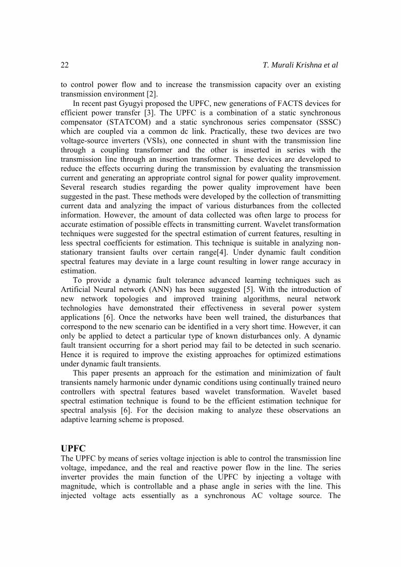
transmission line current flows through this voltage source resulting in a reactive and active power exchange between itself and the ac system. The active power exchanged at the AC terminal is converted into dc power, which appears at the DC link as a positive or negative real power. The basic function of shunt inverter is to generate or absorb the real power demanded by series inverter at the common DC link. The power demand by the series inverter at the DC link is converted back to AC by the shunt inverter and fed to the transmission line bus. The single line UPFC architecture is presented in figure 1.
Figure 1: Single line UPFC Architecture. In addition to this, the shunt inverter can also generate or absorb controllable reactive power if desired and thereby provides independent shunt reactive compensation for the transmission line [6],[7]. The three main control parameters of UPFC are voltage magnitude, voltage angle and shunt reactive current. The transient stability model for the shunt and series branch of a UPFC in the reference frame is given in the literature [8]. This UPFC architecture collects the transmitting current data from shunt-series insertion transformers. These currents could be processed in spectral domain for the feature estimation and fault detection. Neuro controlling The ability to identify the interactions between cause and effect of a system made the neural networks more suitable for modeling and designing intelligent controllers for power systems. A radial basis function (RBF) neural network controller for UPFC, based on the direct adaptive control scheme has been reported to improve the transient stability performance of a power system[9]. It is known that indirect adaptive control is able to control a nonlinear system with dynamics. The main advantage of the neuro controllers over the conventional controllers is that they can adapt to the changes in system operating conditions automatically. The block diagram of the conventional PI controllers for shunt branch and series branch of the UPFC are shown in Figure.2. The control of series inverter can be achieved using PQ-decoupled control. Neglecting the inverter losses, the injected active power Pinj, reactive power Qinj, output active power Pout, and reactive power Qout are given by the following expressions.
24 T. Murali Krishna et al
( cos sin )q q dinj
V E E EP
Xδ δ− +
= (1)
2 22 2cos sind q d d q
inj
VE V E V E E EQ
Xδ δ+ − + +
= (2)
22 2s in q
o u t
V V EP
Xδ +
= (3)
2 22 22 cos 2 sin
2d q d q
out
V E V E E EQ
Xδ δ+ + +
= (4)
Where
2 22
s in ( )
co s( )
d q
q in j in j
d in j in j
V E E
E V
E V
θ
θ
= +
=
=
(5)
It can be seen from equation (3) that Pout is mainly affected by Eq whereas equation (4) shows that Qout is affected by both Eq and Ed. In incremental form, the line active and reactive power can be expressed in terms of ΔEq and ΔEd as follows.
out q
VP EX
Δ = Δ (6)
1 ( cos sin )out d q d do q qoQ E V E V E E E EX
δ δΔ = Δ +Δ +Δ +Δ (7)
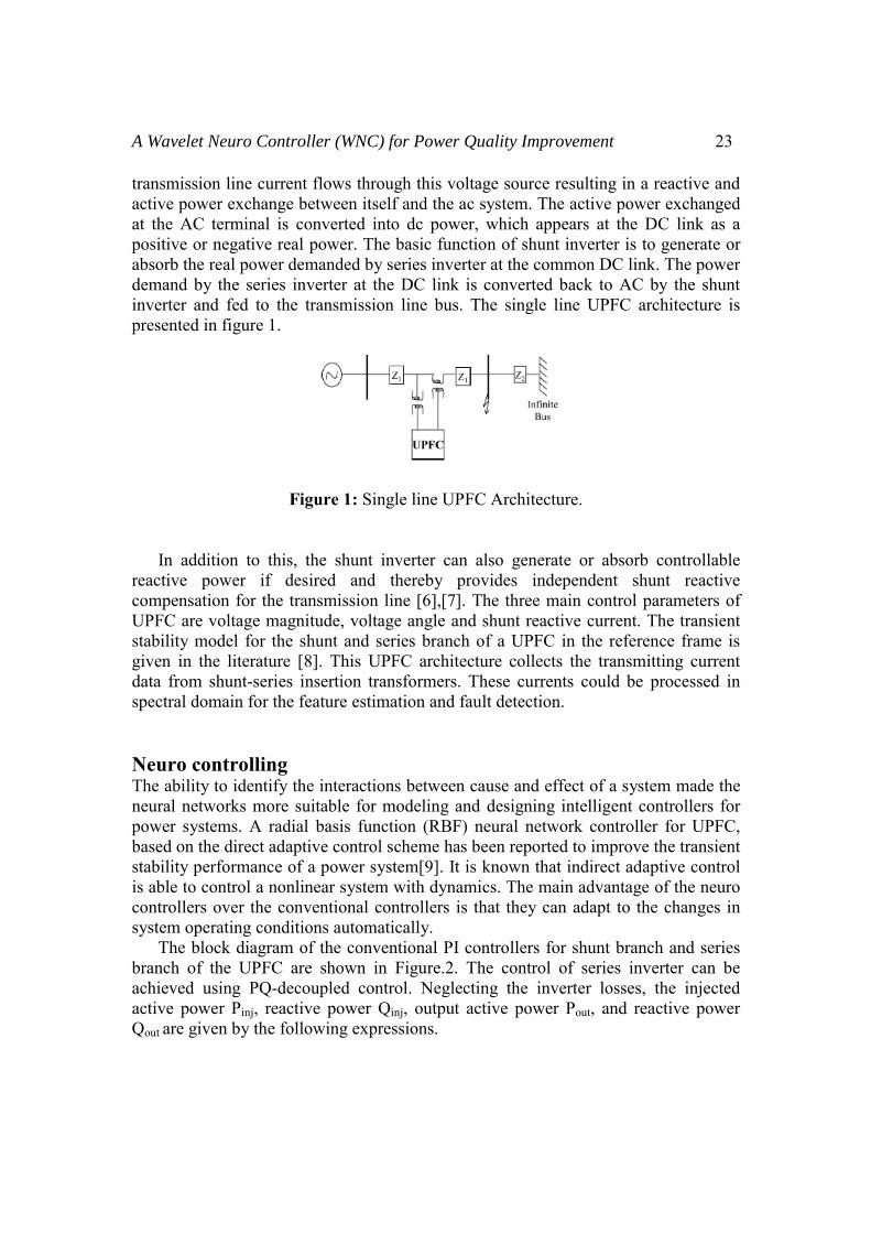
However, it can be assumed in practice that cosδ is close to unity and sinδ is close to zero since the phase angle between the two buses (receiving and sending ends) on a transmission line is less than 30. Control of the shunt active and reactive current is achieved by varying the shunt inverter voltage active component Epd and reactive component Epq, respectively. Figure.2 shows a typical block diagram of the conventional PI controllers for the UPFC shunt branch control [8], [9]. The outputs of this control system are the modulation index k and phase shift α. The PI controllers are replaced by the neuro controllers.
Figure 2: Shunt & series inverter control with PI controllers.
A Wavelet Neuro Controll
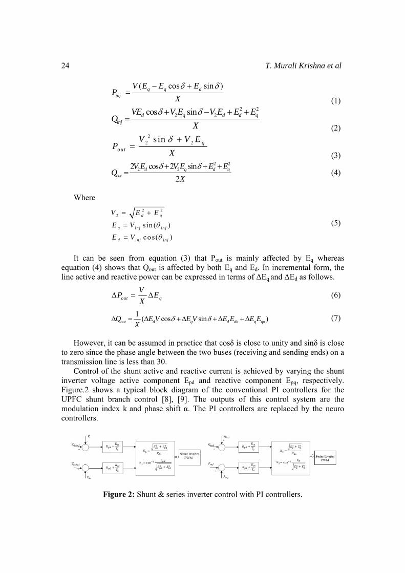
Two neuro identifiers inverter are used to identiThese networks dynamicΔEpq,ΔEp, ΔEq which are tthe series-parallel NonlinThe two neuroidentifiers dynamic models at all timpre-control phase and a po The series branch neurneural network with 13 intwo outputs. There are twnamely, the forced trainidynamics of the system asystem.
Fig During natural trainingthe controller can be a coneural controllers design u Proposed Approach
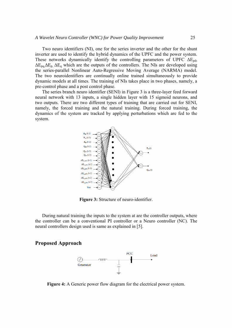
Figure 4: A Generi
ler (WNC) for Power Quality Improvement
(NI), one for the series inverter and the othefy the hybrid dynamics of the UPFC and thecally identify the controlling parameters othe outputs of the controllers. The NIs are d
near Auto-Regressive Moving Average (NAare continually online trained simultaneou
mes. The training of NIs takes place in two phost control phase. ro identifier (SENI) in Figure 3 is a three-laynputs, a single hidden layer with 15 sigmoi
wo different types of training that are carrieding and the natural training. During forceare tracked by applying perturbations which
gure 3: Structure of neuro-identifier.
g the inputs to the system at are the controlleronventional PI controller or a Neuro controused is same as explained in [5].
c power flow diagram for the electrical powe
25
er for the shunt e power system. of UPFC ΔEpd, developed using ARMA) model. usly to provide hases, namely, a
yer feed forward id neurons, and d out for SENI, ed training, the h are fed to the
r outputs, where oller (NC). The
er system.
26 T. Murali Krishna et al
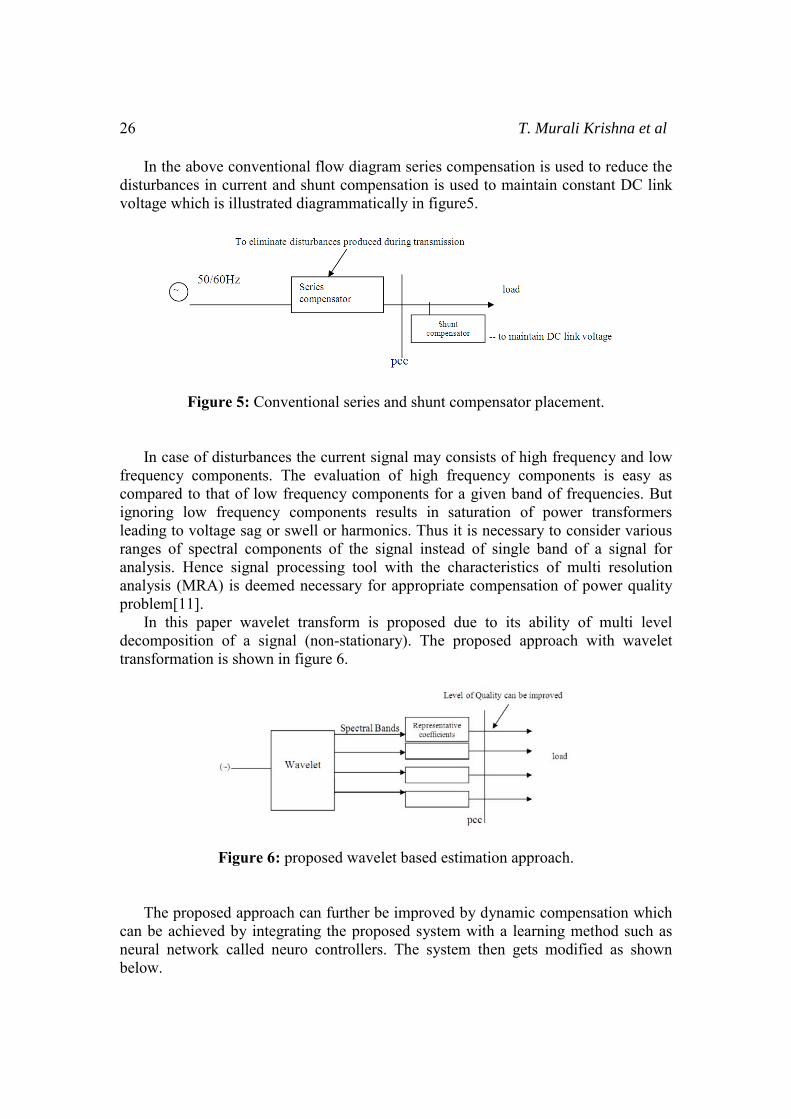
In the above conventional flow diagram series compensation is used to reduce the disturbances in current and shunt compensation is used to maintain constant DC link voltage which is illustrated diagrammatically in figure5.
Figure 5: Conventional series and shunt compensator placement. In case of disturbances the current signal may consists of high frequency and low frequency components. The evaluation of high frequency components is easy as compared to that of low frequency components for a given band of frequencies. But ignoring low frequency components results in saturation of power transformers leading to voltage sag or swell or harmonics. Thus it is necessary to consider various ranges of spectral components of the signal instead of single band of a signal for analysis. Hence signal processing tool with the characteristics of multi resolution analysis (MRA) is deemed necessary for appropriate compensation of power quality problem[11]. In this paper wavelet transform is proposed due to its ability of multi level decomposition of a signal (non-stationary). The proposed approach with wavelet transformation is shown in figure 6.
Figure 6: proposed wavelet based estimation approach. The proposed approach can further be improved by dynamic compensation which can be achieved by integrating the proposed system with a learning method such as neural network called neuro controllers. The system then gets modified as shown below.
A Wavelet Neuro Controller (WNC) for Power Quality Improvement 27
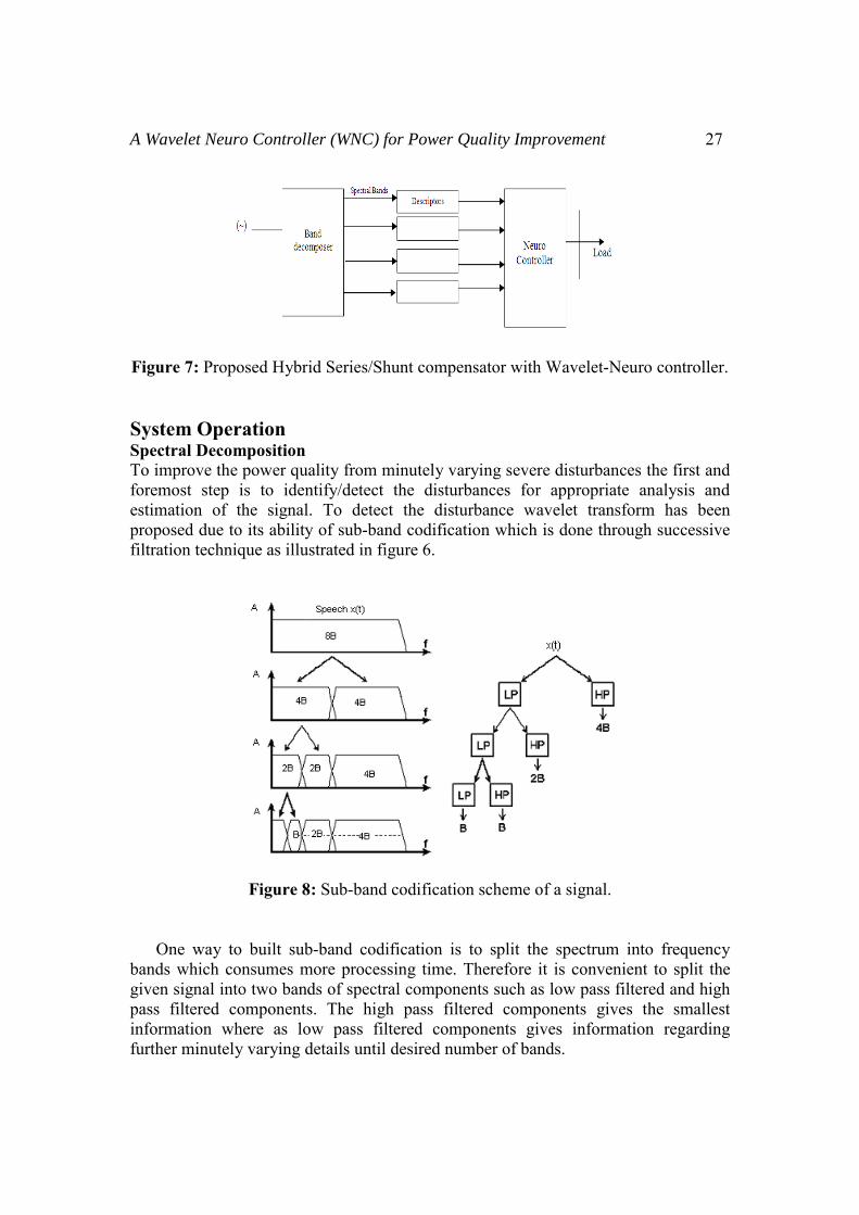
Figure 7: Proposed Hybrid Series/Shunt compensator with Wavelet-Neuro controller. System Operation Spectral Decomposition To improve the power quality from minutely varying severe disturbances the first and foremost step is to identify/detect the disturbances for appropriate analysis and estimation of the signal. To detect the disturbance wavelet transform has been proposed due to its ability of sub-band codification which is done through successive filtration technique as illustrated in figure 6.
Figure 8: Sub-band codification scheme of a signal. One way to built sub-band codification is to split the spectrum into frequency bands which consumes more processing time. Therefore it is convenient to split the given signal into two bands of spectral components such as low pass filtered and high pass filtered components. The high pass filtered components gives the smallest information where as low pass filtered components gives information regarding further minutely varying details until desired number of bands.
28 T. Murali Krishna et al
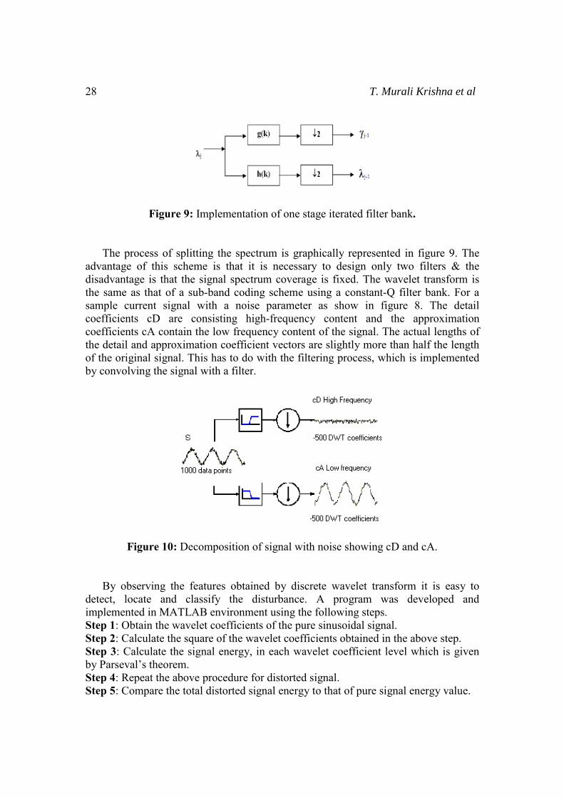
Figure 9: Implementation of one stage iterated filter bank. The process of splitting the spectrum is graphically represented in figure 9. The advantage of this scheme is that it is necessary to design only two filters & the disadvantage is that the signal spectrum coverage is fixed. The wavelet transform is the same as that of a sub-band coding scheme using a constant-Q filter bank. For a sample current signal with a noise parameter as show in figure 8. The detail coefficients cD are consisting high-frequency content and the approximation coefficients cA contain the low frequency content of the signal. The actual lengths of the detail and approximation coefficient vectors are slightly more than half the length of the original signal. This has to do with the filtering process, which is implemented by convolving the signal with a filter.
Figure 10: Decomposition of signal with noise showing cD and cA. By observing the features obtained by discrete wavelet transform it is easy to detect, locate and classify the disturbance. A program was developed and implemented in MATLAB environment using the following steps. Step 1: Obtain the wavelet coefficients of the pure sinusoidal signal. Step 2: Calculate the square of the wavelet coefficients obtained in the above step. Step 3: Calculate the signal energy, in each wavelet coefficient level which is given by Parseval’s theorem. Step 4: Repeat the above procedure for distorted signal. Step 5: Compare the total distorted signal energy to that of pure signal energy value.
A Wavelet Neuro Controller (WNC) for Power Quality Improvement 29
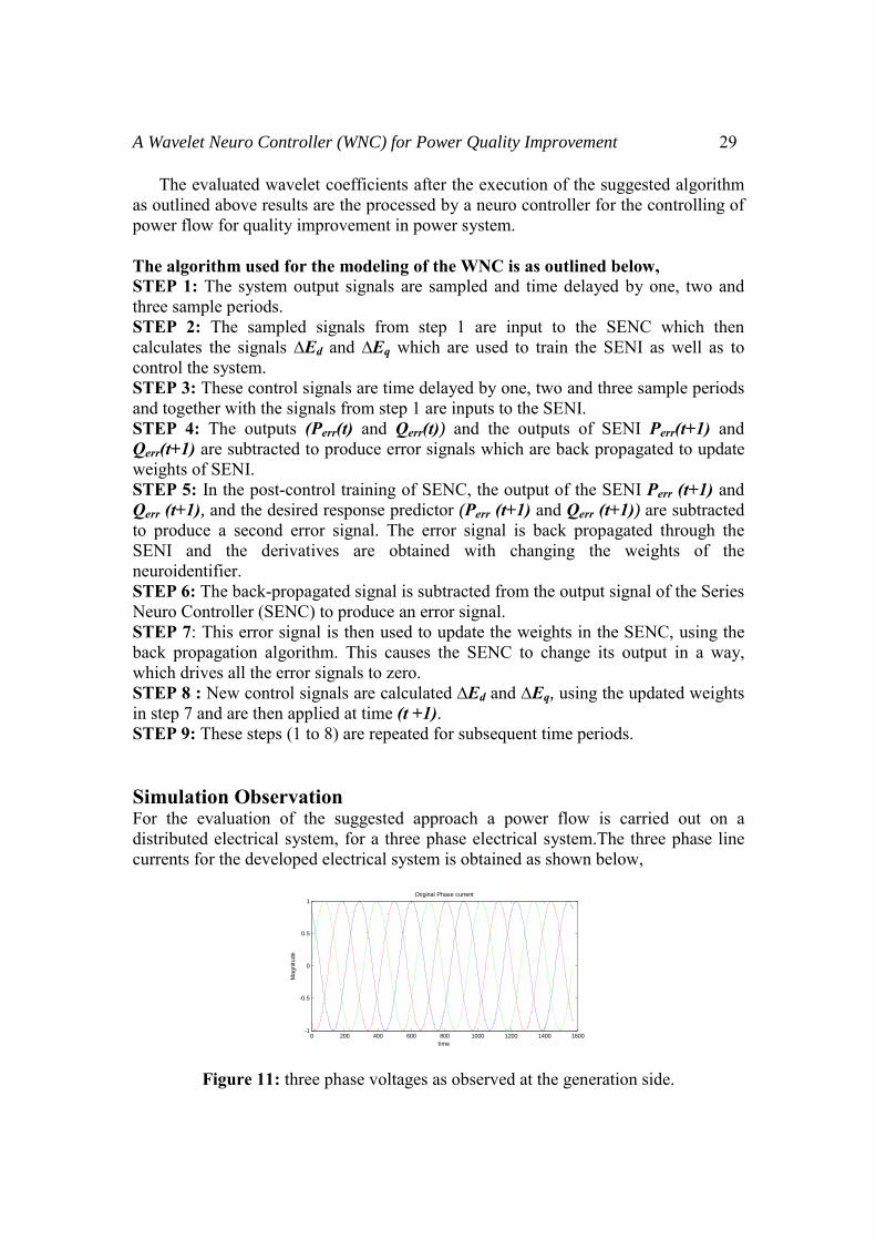
The evaluated wavelet coefficients after the execution of the suggested algorithm as outlined above results are the processed by a neuro controller for the controlling of power flow for quality improvement in power system. The algorithm used for the modeling of the WNC is as outlined below, STEP 1: The system output signals are sampled and time delayed by one, two and three sample periods. STEP 2: The sampled signals from step 1 are input to the SENC which then calculates the signals ∆Ed and ∆Eq which are used to train the SENI as well as to control the system. STEP 3: These control signals are time delayed by one, two and three sample periods and together with the signals from step 1 are inputs to the SENI. STEP 4: The outputs (Perr(t) and Qerr(t)) and the outputs of SENI Perr(t+1) and Qerr(t+1) are subtracted to produce error signals which are back propagated to update weights of SENI. STEP 5: In the post-control training of SENC, the output of the SENI Perr (t+1) and Qerr (t+1), and the desired response predictor (Perr (t+1) and Qerr (t+1)) are subtracted to produce a second error signal. The error signal is back propagated through the SENI and the derivatives are obtained with changing the weights of the neuroidentifier. STEP 6: The back-propagated signal is subtracted from the output signal of the Series Neuro Controller (SENC) to produce an error signal. STEP 7: This error signal is then used to update the weights in the SENC, using the back propagation algorithm. This causes the SENC to change its output in a way, which drives all the error signals to zero. STEP 8 : New control signals are calculated ∆Ed and ∆Eq, using the updated weights in step 7 and are then applied at time (t +1). STEP 9: These steps (1 to 8) are repeated for subsequent time periods. Simulation Observation For the evaluation of the suggested approach a power flow is carried out on a distributed electrical system, for a three phase electrical system.The three phase line currents for the developed electrical system is obtained as shown below,
Figure 11: three phase voltages as observed at the generation side.
0 200 400 600 800 1000 1200 1400 1600-1
-0.5
0
0.5
1
time
Mag
nitu
de
Original Phase current
30 T. Murali Krishna et al
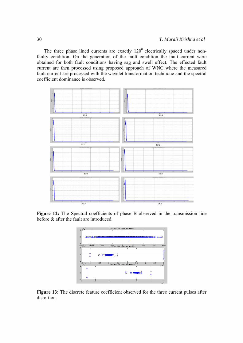
The three phase lined currents are exactly 1200 electrically spaced under non-faulty condition. On the generation of the fault condition the fault current were obtained for both fault conditions having sag and swell effect. The effected fault current are then processed using proposed approach of WNC where the measured fault current are processed with the wavelet transformation technique and the spectral coefficient dominance is observed.
Figure 12: The Spectral coefficients of phase B observed in the transmission line before & after the fault are introduced.
Figure 13: The discrete feature coefficient observed for the three current pulses after distortion.
A Wavelet Neuro Controller (WNC) for Power Quality Improvement 31
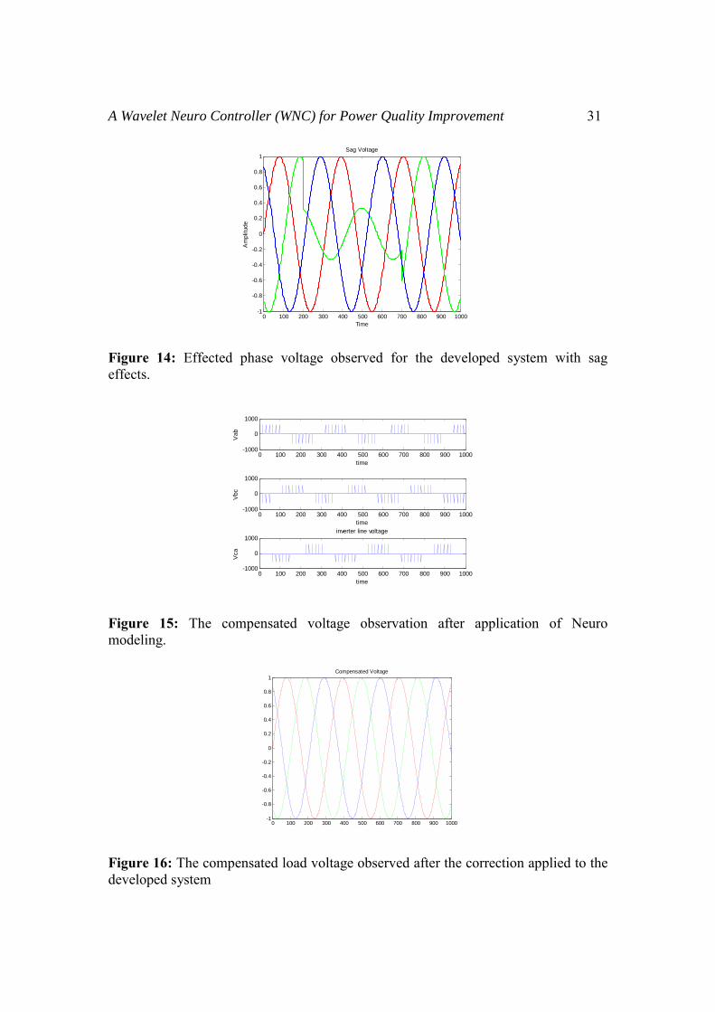
Figure 14: Effected phase voltage observed for the developed system with sag effects.
Figure 15: The compensated voltage observation after application of Neuro modeling.
Figure 16: The compensated load voltage observed after the correction applied to the developed system
0 100 200 300 400 500 600 700 800 900 1000-1
-0.8
-0.6
-0.4
-0.2
0
0.2
0.4
0.6
0.8
1Sag Voltage
Time
Am
plitu
de
0 100 200 300 400 500 600 700 800 900 1000-1000
0
1000
time
Vab
0 100 200 300 400 500 600 700 800 900 1000-1000
0
1000
time
Vbc
0 100 200 300 400 500 600 700 800 900 1000-1000
0
1000
time
Vca
inverter line voltage
0 100 200 300 400 500 600 700 800 900 1000-1
-0.8
-0.6
-0.4
-0.2
0
0.2
0.4
0.6
0.8
1Compensated Voltage
32 T. Murali Krishna et al
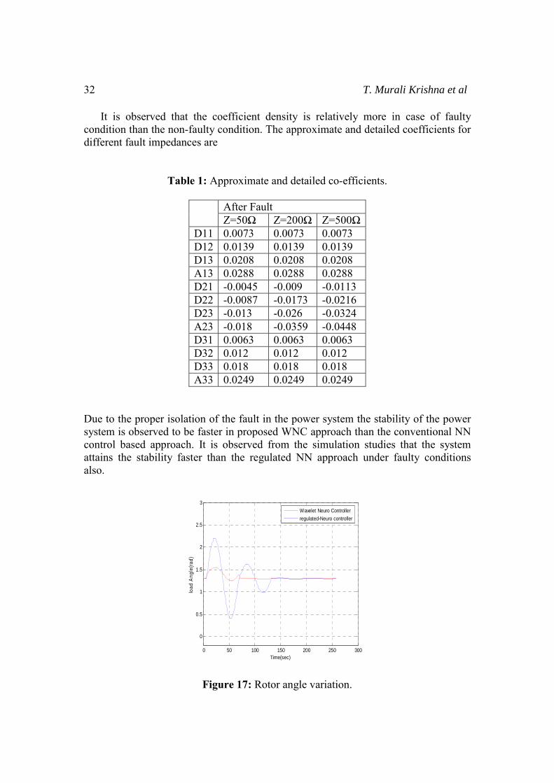
It is observed that the coefficient density is relatively more in case of faulty condition than the non-faulty condition. The approximate and detailed coefficients for different fault impedances are
Table 1: Approximate and detailed co-efficients.
After Fault Z=50Ω Z=200Ω Z=500Ω
D11 0.0073 0.0073 0.0073 D12 0.0139 0.0139 0.0139 D13 0.0208 0.0208 0.0208 A13 0.0288 0.0288 0.0288 D21 -0.0045 -0.009 -0.0113 D22 -0.0087 -0.0173 -0.0216 D23 -0.013 -0.026 -0.0324 A23 -0.018 -0.0359 -0.0448 D31 0.0063 0.0063 0.0063 D32 0.012 0.012 0.012 D33 0.018 0.018 0.018 A33 0.0249 0.0249 0.0249
Due to the proper isolation of the fault in the power system the stability of the power system is observed to be faster in proposed WNC approach than the conventional NN control based approach. It is observed from the simulation studies that the system attains the stability faster than the regulated NN approach under faulty conditions also.
Figure 17: Rotor angle variation.
0 50 100 150 200 250 300
0
0.5
1
1.5
2
2.5
3
Time(sec)
load
Ang
le(ra
d)
Wavelet Neuro Controllerregulated-Neuro controller
A Wavelet Neuro Controller (WNC) for Power Quality Improvement 33
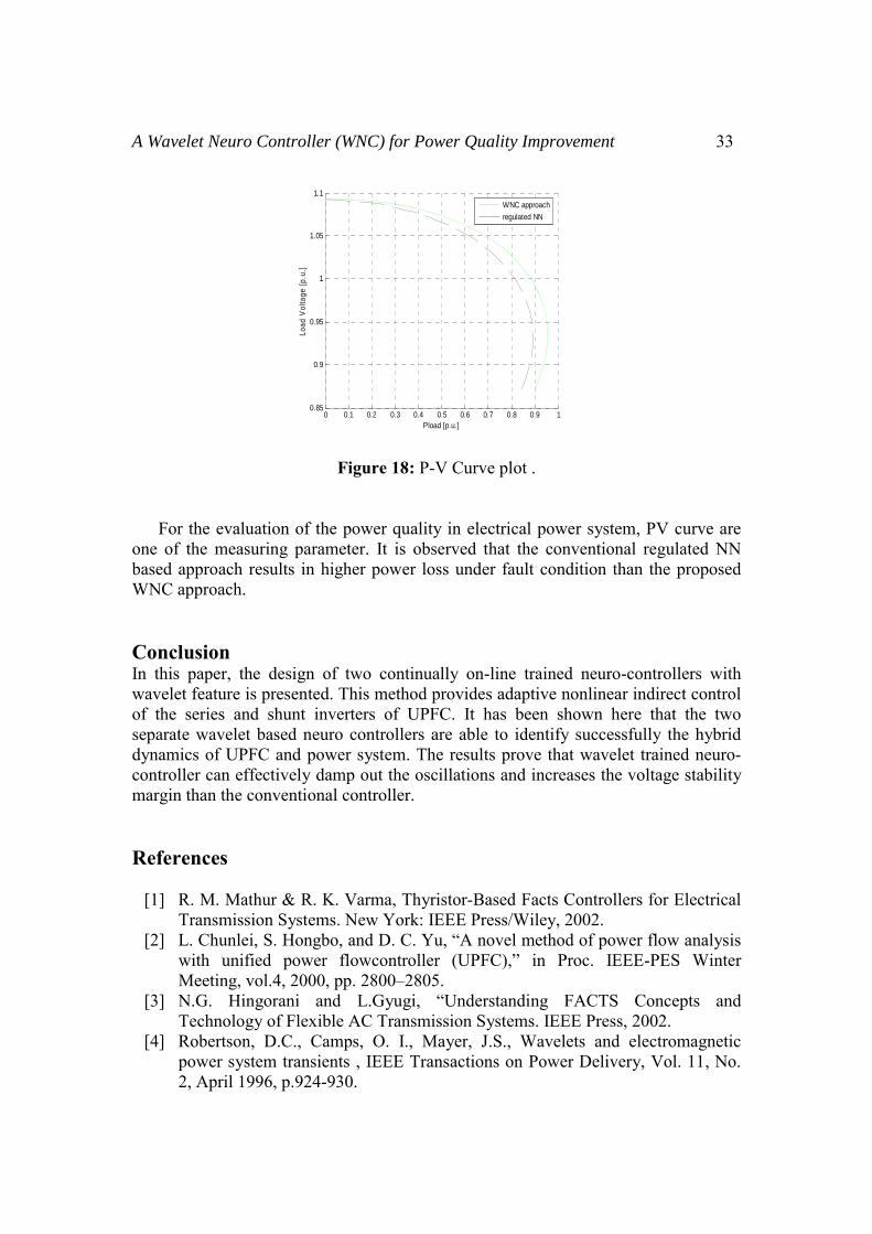
Figure 18: P-V Curve plot .
For the evaluation of the power quality in electrical power system, PV curve are one of the measuring parameter. It is observed that the conventional regulated NN based approach results in higher power loss under fault condition than the proposed WNC approach. Conclusion In this paper, the design of two continually on-line trained neuro-controllers with wavelet feature is presented. This method provides adaptive nonlinear indirect control of the series and shunt inverters of UPFC. It has been shown here that the two separate wavelet based neuro controllers are able to identify successfully the hybrid dynamics of UPFC and power system. The results prove that wavelet trained neuro-controller can effectively damp out the oscillations and increases the voltage stability margin than the conventional controller. References
[1] R. M. Mathur & R. K. Varma, Thyristor-Based Facts Controllers for Electrical Transmission Systems. New York: IEEE Press/Wiley, 2002.
[2] L. Chunlei, S. Hongbo, and D. C. Yu, “A novel method of power flow analysis with unified power flowcontroller (UPFC),” in Proc. IEEE-PES Winter Meeting, vol.4, 2000, pp. 2800–2805.
[3] N.G. Hingorani and L.Gyugi, “Understanding FACTS Concepts and Technology of Flexible AC Transmission Systems. IEEE Press, 2002.
[4] Robertson, D.C., Camps, O. I., Mayer, J.S., Wavelets and electromagnetic power system transients , IEEE Transactions on Power Delivery, Vol. 11, No. 2, April 1996, p.924-930.
0 0.1 0.2 0.3 0.4 0.5 0.6 0.7 0.8 0.9 10.85
0.9
0.95
1
1.05
1.1
Pload [p.u.]
Load
Vol
tage
[p.u
.]
WNC approachregulated NN
34 T. Murali Krishna et al
[5] G. K. Venayagamoorthy and R. G. Harley, “Two separate continually online-trained neurocontrollers for excitation and turbine control of a turbo generator,” IEEE Trans. Ind. Appl., vol. 38, no. 3, pp. 887–893,May/Jun. 2002.
[6] “A continually online trained neurocontroller for excitation and turbine control of a turbo generator,” IEEE Trans. Energy Convers., vol. 16, no. 3, pp. 261–269, Sep. 2001.
[7] Gaouda. A. M., Salama. M. M. A., Sultan M. R., Chikhani. A.Y., Power quality detection and classification using wavelet-multi resolution signal decomposition, IEEE Transactions on Power Delivery, Vol.14, No. 4, October 1999, p. 1469-1476.
[8] R. P. Kalyani and G. K. Venayagamoorthy, “A continually online trained neurocontroller for the series branch control of the UPFC,” in Proc. INNS-IEEE Int. Joint Conf. Neural Networks, vol. 4, Jul. 2003, pp. 2982–2987.
[9] P. K. Dash, S. Mishra, and G. Panda, “A radial basis function neural network controller for UPFC,” IEEE Trans. Power Syst., vol. 15, no. 4, pp. 1293-1299, Nov. 2000.
[10] L. Y. Dong, L. Zhang, and M. L. Crow, “A new control strategy for the unified power flow controller,” in Proc. IEEE-PES Winter Meeting, vol. 1, 2002, pp. 562–566.
[11] Burrus,C. S., Gopinath, A. R., Wickerhauser, M. V., Wavelets and time frequency analysis , Proceedings of the IEEE, vol. 84, No. 4, April 1996, pp. 523-540.