Embed Size (px)
Citation preview
June 1, 2004 2:11 WSPC/INSTRUCTION FILE ws-ijhr
International Journal of Humanoid Roboticsc© World Scientific Publishing Company
The Power of the Dark Side:
Using Cast Shadows for Visually-Guided Touching
Paul M. Fitzpatrick and Eduardo R. Torres-Jara
Computer Science and Artificial Intelligence Laboratory
Massachusetts Institute of Technology
Cambridge, Massachusetts 02139, USA
{paulfitz,etorresj}@csail.mit.edu
Received (Day Month Year)Revised (Day Month Year)Accepted (Day Month Year)
A humanoid robot needs to be able to operate safely in human workspaces, prefer-ably without extensive calibration. We consider the problem of directing a robot armtowards, across, and away from an unmodeled surface without damaging it. For thistask we make use of a powerful resource: the shadow cast by the robot’s own body. We
show that the cast shadow of the arm on the surface can be detected by a camera andused to derive a time-to-contact estimate. This estimate, when combined with the 2Dtracked location of the arm’s endpoint in the camera image, is sufficient to allow 3Dcontrol relative to the surface. We show that the same method can detect either castshadows or reflections, allowing the robot to operate correctly over water, mirrors, orother reflective materials. Such scenarios, along with low-texture surfaces, are cases inwhich stereo vision – the more commonly used depth cue in robotics – might fail andis worth augmenting. We draw on the literature of computer graphics and virtual real-ity to argue that for manipulation, sensitivity to shadows and interreflection will be ofsimilar importance to stereo vision as a depth cue when attempting to touch an object.In computer vision, shadows are generally treated as a nuisance, but that doesn’t meanroboticists should do the same.
Keywords: humanoid robotics; shadows; time to contact; depth perception; manipulation
1. Introduction
Shadows have long been a bane of computer vision, creating illusory objects and
obscuring true object boundaries. Much energy has been devoted to developing the
means to detect shadows automatically, not because they are considered valuable
in themselves, but because they need to be distinguished from true objects 1. On
the other hand, researchers in computer graphics and virtual reality have struggled
to render shadows in order to increase realism and aid depth perception 2. Robotics
draws on all these fields, so should we be fans or foes of shadows?
In this paper we observe that in visually-guided reaching, perception of the
shadow(s) cast by a robot arm is potentially very useful. As the arm approaches
a surface, the shadow that it casts rushes to meet it. This gives an indication of
1
June 1, 2004 2:11 WSPC/INSTRUCTION FILE ws-ijhr
2 Fitzpatrick, Torres-Jara
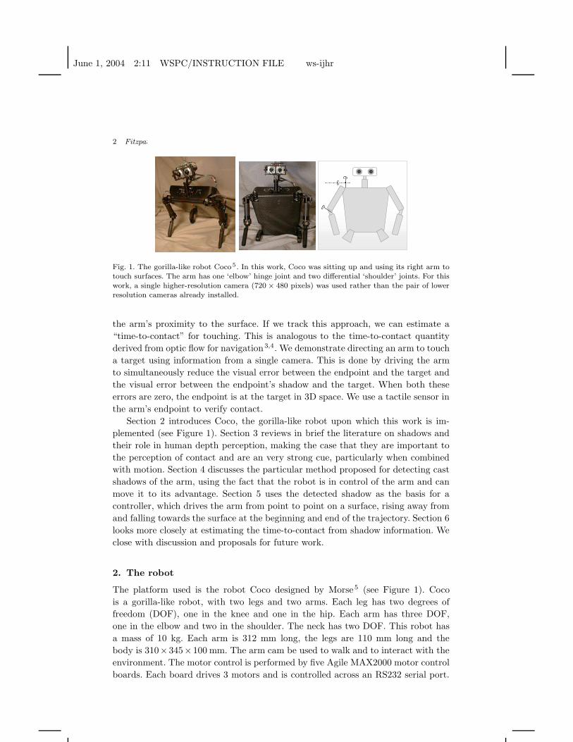
Fig. 1. The gorilla-like robot Coco 5 . In this work, Coco was sitting up and using its right arm totouch surfaces. The arm has one ‘elbow’ hinge joint and two differential ‘shoulder’ joints. For thiswork, a single higher-resolution camera (720 × 480 pixels) was used rather than the pair of lowerresolution cameras already installed.
the arm’s proximity to the surface. If we track this approach, we can estimate a
“time-to-contact” for touching. This is analogous to the time-to-contact quantity
derived from optic flow for navigation3,4. We demonstrate directing an arm to touch
a target using information from a single camera. This is done by driving the arm
to simultaneously reduce the visual error between the endpoint and the target and
the visual error between the endpoint’s shadow and the target. When both these
errors are zero, the endpoint is at the target in 3D space. We use a tactile sensor in
the arm’s endpoint to verify contact.
Section 2 introduces Coco, the gorilla-like robot upon which this work is im-
plemented (see Figure 1). Section 3 reviews in brief the literature on shadows and
their role in human depth perception, making the case that they are important to
the perception of contact and are an very strong cue, particularly when combined
with motion. Section 4 discusses the particular method proposed for detecting cast
shadows of the arm, using the fact that the robot is in control of the arm and can
move it to its advantage. Section 5 uses the detected shadow as the basis for a
controller, which drives the arm from point to point on a surface, rising away from
and falling towards the surface at the beginning and end of the trajectory. Section 6
looks more closely at estimating the time-to-contact from shadow information. We
close with discussion and proposals for future work.
2. The robot
The platform used is the robot Coco designed by Morse5 (see Figure 1). Coco
is a gorilla-like robot, with two legs and two arms. Each leg has two degrees of
freedom (DOF), one in the knee and one in the hip. Each arm has three DOF,
one in the elbow and two in the shoulder. The neck has two DOF. This robot has
a mass of 10 kg. Each arm is 312 mm long, the legs are 110 mm long and the
body is 310×345×100 mm. The arm cam be used to walk and to interact with the
environment. The motor control is performed by five Agile MAX2000 motor control
boards. Each board drives 3 motors and is controlled across an RS232 serial port.
June 1, 2004 2:11 WSPC/INSTRUCTION FILE ws-ijhr
Using Cast Shadows for Visually-Guided Touching 3
In the tip of the arm there is a force sensor with a resolution of 120 mV/kg and a
limit of 0.5 kg.
The vision system consists of a Sony camcorder with a resolution of 720 × 480
pixels and controllable zoom and focus. The control is done by a custom board that
interfaces the LANC port of the camera to a RS232 port. The camera connects to
an offboard computer running Linux through its IEEE 1394 (Firewire) interface.
This computer runs the vision system described in the remainder of this paper, and
communicates via TCP/IP with a second computer charged with motor control and
interfacing with the motor control boards.
3. The role of shadows in human perception of depth
Many cues play a role in the human perception of depth, including occlusions,
stereopsis, motion parallax, shadows (attached or cast), interreflections, perspective
effects, etc. Over the centuries these cues have become better understood in art;
the idea of perspective, for example, first gained currency in the 15th century. In
this century, the need to understand depth perception has grown in urgency as
researchers in computer graphics and virtual reality strive for increasing realism.
Stereopsis has proven to be an important cue; shadows and interreflections have also
proven effective, and in some cases match stereopsis in power 6,7,8,2. Moving shadows
can profoundly influence the interpretation of a scene, in some cases overruling other
depth cues such as apparent size9,10. Apparent shadow motion can give a very strong
sense of object motion even in the absence of any other cue 11. Shadows help in the
perception of spatial relationships in computer-generated images 12. Shadows and
interreflections are particularly important for giving a strong impression of object
contact in computer graphics13.
There is speculation that the cast shadow of the hand may be integrated into
the body schema, in a manner somewhat analogous to the extension of the schema
to include tools14. There is some evidence that the processing of shadows in the
brain, which can impact on object recognition performance, is at least partially
done without conscious awareness15.
In computer vision, shadows cannot be ignored. Much work has been devoted to
detecting them, even if only for the purposes of discounting them16 (for a review,
see Prati et al1). Less common is work to utilize shadows. In computer graphics, it
was realized that the cast shadow of a known object (a long stick) could be used
to recover the shape of an object the shadow passed over, in a manner analogous
to (but cheaper than) active illumination methods that scan lines of light across
the scene17. Shadow has also been used to recover body pose in video of moving
people18. There is a great deal of work on ‘shape from shadow’ which is generally
concerned with shading rather than cast shadows.
To summarize, shadows have a demonstrable and significant impact on the abil-
ity of humans to perceive depth and adjacency, and to judge whether an object
and a surface are in contact. We wish to import that advantage into robotics,
June 1, 2004 2:11 WSPC/INSTRUCTION FILE ws-ijhr
4 Fitzpatrick, Torres-Jara
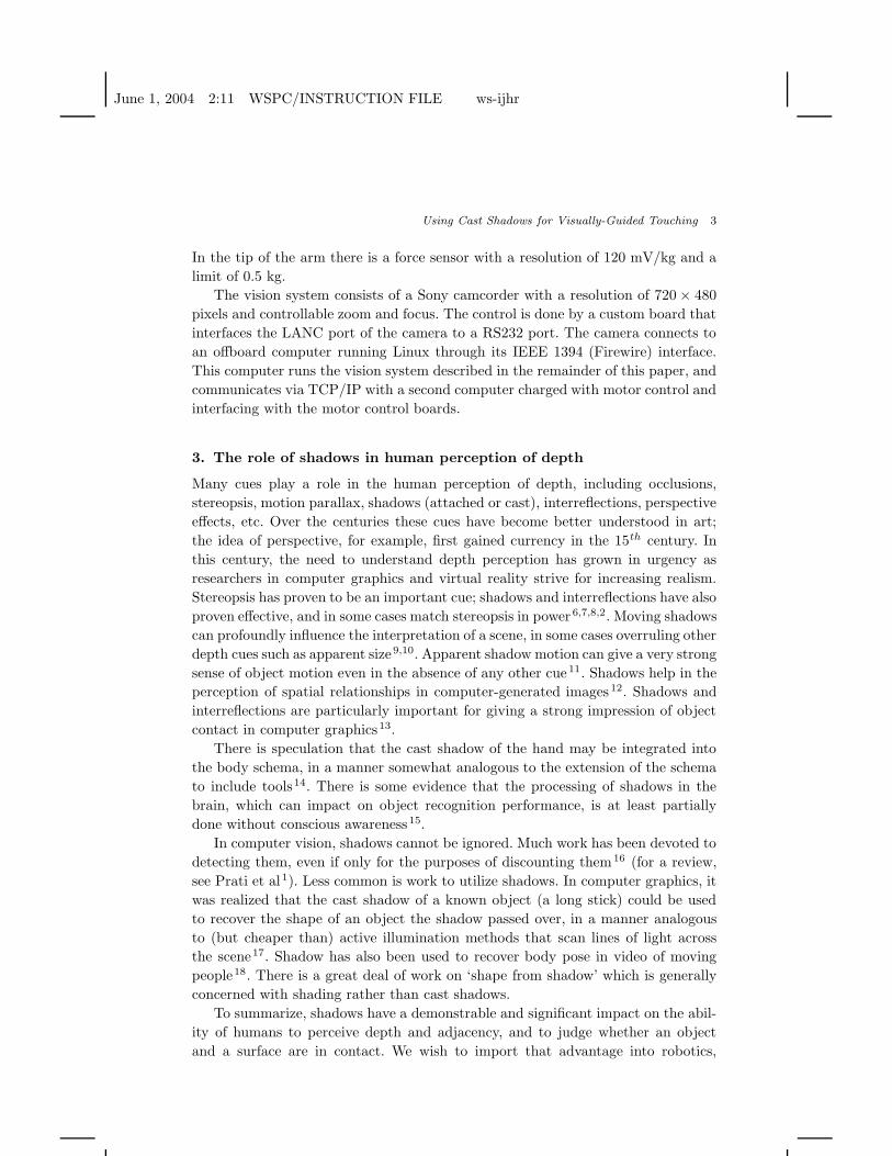
Endpoint marker
Shadow marker
Fig. 2. Detection of the arm endpoint (shown as a circle) and the arm’s shadow (shown as a bar).The surfaces shown are a cardboard box, a metal table, and a text-covered box, all at differentdistances from the robot. Lighting varies from ambient (where the shadow is barely perceptible tothe human eye) to strongly directional, from left or right.
rather than continue to rely only on stereo vision for depth perception. Shadows
and stereopsis have somewhat complementary properties; stereo is at is best when
depth changes are sharp, while shadows are easiest to track when depth changes
are relatively smooth. The error in stereo measurements grows with distance from
the camera, while the error in shadow measurements grows with distance from the
surface. Shadows (and reflections) are detectable even in the absence of texture, or
with reflective surfaces, situations that can confuse stereo. We believe that combin-
ing stereopsis and shadows could lead to a more robust system for manipulation. In
this paper we seek to show the benefits of shadows on their own, but that should
not be read as a belief that shadows are better than stereo.
4. Detecting cast shadows of the arm
What properties of a cast shadow can be used to reveal its presence? The most
obvious property of a cast shadow is that the surface it is cast on becomes darker
than it otherwise would be. In a single image, this is not very helpful, since we
do not know how dark different surfaces should be, and the appearance of surfaces
varies for many reasons other than shadows. In a video stream, this property is more
helpful, since we can watch for moving patches of darkness, or compare against an
image of the background without the arm or its shadow present.
For this work, two methods are used for detecting regions of illumination change,
labeled static and dynamic. The static method is based on building a background
model of the workspace while holding the arm to the side, then looking for novel
regions of illumination change relative to that model when the arm swings into
June 1, 2004 2:11 WSPC/INSTRUCTION FILE ws-ijhr
Using Cast Shadows for Visually-Guided Touching 5
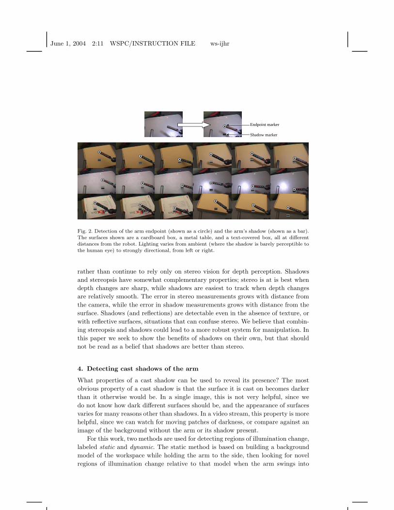
Fig. 3. Another form of illumination change that can occur is a reflection. The method describedfor shadow detection works without change to detect reflections. The top row shows the reflectionof the arm being detected in a small mirror. The middle row shows reflections in a dark bowl ofwater, and the bottom row shows reflections and shadows on a sheet of acrylic, partially covered.
action. This method can detect very weak shadows, and operates just as well when
the arm is stationary as when it is moving. The dynamic method specifically looks
for moving regions of illumination change, by comparing the current image from
the camera with one from half a second ago. This gives better localization of the
shadow of the endpoint (the fastest moving part of the arm) while the robot is in
motion, but is useless when the robot is stationary.
The first step in finding the cast shadow is to find the endpoint of the arm itself,
as a reference. The endpoint of the arm is tracked at 30Hz. In each frame, a small
window (1/25 of the image area) around the last known position of the endpoint
is scanned for the dominant local orientation within ±5◦ of the arm’s last known
orientation. It is assumed this dominant orientation will be due to the edges of the
arm and the highlights running along its length. The tracked position of the arm is
then updated to the center of mass of the pixels that are at the dominant orientation,
with a small constant offset in the direction of the orientation. When iterated, this
procedure drives the tracked position out along the arm to the endpoint, and pulls
it back in if it begins to drift. The tracking procedure makes minimal assumptions
about the endpoint. The tracker is initialized using an appearance model of the arm
and an assumption that the arm is initially in an area with good contrast with the
background.
Once the position of the endpoint is known, the vision system waits for an op-
portunity to build a background model. This is provided by simply swinging the
endpoint to the side, out of the way. The background model is simply a snapshot
June 1, 2004 2:11 WSPC/INSTRUCTION FILE ws-ijhr
6 Fitzpatrick, Torres-Jara
Robot sees target, arm, and arm’s shadow
Robot moves to reducevisual error between
arm and target
Robot moves to reducevisual error between
arm’s shadow and target
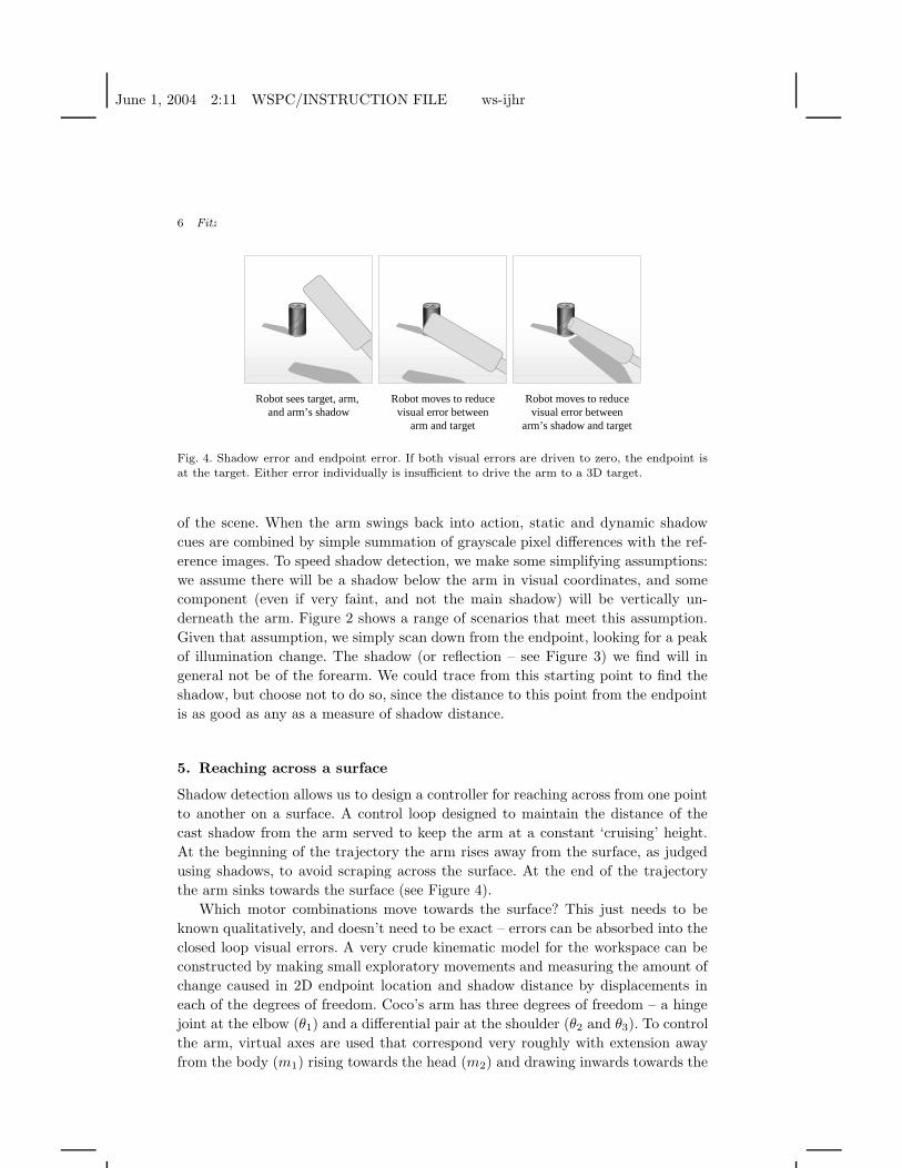
Fig. 4. Shadow error and endpoint error. If both visual errors are driven to zero, the endpoint isat the target. Either error individually is insufficient to drive the arm to a 3D target.
of the scene. When the arm swings back into action, static and dynamic shadow
cues are combined by simple summation of grayscale pixel differences with the ref-
erence images. To speed shadow detection, we make some simplifying assumptions:
we assume there will be a shadow below the arm in visual coordinates, and some
component (even if very faint, and not the main shadow) will be vertically un-
derneath the arm. Figure 2 shows a range of scenarios that meet this assumption.
Given that assumption, we simply scan down from the endpoint, looking for a peak
of illumination change. The shadow (or reflection – see Figure 3) we find will in
general not be of the forearm. We could trace from this starting point to find the
shadow, but choose not to do so, since the distance to this point from the endpoint
is as good as any as a measure of shadow distance.
5. Reaching across a surface
Shadow detection allows us to design a controller for reaching across from one point
to another on a surface. A control loop designed to maintain the distance of the
cast shadow from the arm served to keep the arm at a constant ‘cruising’ height.
At the beginning of the trajectory the arm rises away from the surface, as judged
using shadows, to avoid scraping across the surface. At the end of the trajectory
the arm sinks towards the surface (see Figure 4).
Which motor combinations move towards the surface? This just needs to be
known qualitatively, and doesn’t need to be exact – errors can be absorbed into the
closed loop visual errors. A very crude kinematic model for the workspace can be
constructed by making small exploratory movements and measuring the amount of
change caused in 2D endpoint location and shadow distance by displacements in
each of the degrees of freedom. Coco’s arm has three degrees of freedom – a hinge
joint at the elbow (θ1) and a differential pair at the shoulder (θ2 and θ3). To control
the arm, virtual axes are used that correspond very roughly with extension away
from the body (m1) rising towards the head (m2) and drawing inwards towards the
June 1, 2004 2:11 WSPC/INSTRUCTION FILE ws-ijhr
Using Cast Shadows for Visually-Guided Touching 7
chest (m3), which are related to the physical axes as follows:
θ1 = m1
θ2 = m1 + m2 + m3
θ3 = m1 − m2 + m3
Drawing inwards towards the chest (m3) is achieved by driving the differential
shoulder motors θ2 and θ3 in lock-step. Rising towards the head (m2) is similar,
but now the differential motors are driven in opposition. Extension of the arm (m1)
is achieved by moving the elbow joint, then compensating at the shoulder by the
same angle to keep the endpoint moving out along a ray from the shoulder.
We wish to be able to move the endpoint of the arm, detected in visual co-
ordinates, towards a target also defined in visual coordinates, while controlling
the height of the arm above a surface (estimated from the behavior of the arm’s
shadow). When the robot’s gaze is directed downwards at a workspace, the virtual
axes correspond very approximately to variables we would like to control. Changing
m2 (rotation towards the head) is approximately what we need to control depth,
whereas m1 and m3 will have a big impact on moving the position of the arm across
the image while having a lesser impact on its depth.
Since we can also recover the projected angle of the arm in the image, which
for the geometry of this robot is an approximate indicator of rotation towards
the chest (m3), desired visual displacements can be expressed in terms of desired
visual rotation and extension of the arm. These quantities can be controlled coarsely
using m2 and m3. We label the three visual control quantities as v1 (desired visual
extension of the arm), v2 (desired visual distance to shadow), and v3 (desired visual
rotation of the arm). To discover the relationship between the observed variables
and the control variables, the robot makes exploratory movements that start small,
then grow until it sees significant changes in at least one of the observed variables.
The result of this exploration will be somewhat dependent on the geometry of the
surface and the location of the arm – here is the result of a typical run:
∆v1
∆v2
∆v3
=
8.1 6.3 −4.4
8.4 10.8 −7.1
3.9 1.9 11.3
∆m1
∆m2
∆m3
Note that ∆m1 has its strongest influence on ∆v1, ∆m2 has its strongest influ-
ence on ∆v2, and ∆m3 has its strongest influence on ∆v3, which corresponds to the
general intuition. We can invert this relationship to produce a reasonable controller:
∆m1
∆m2
∆m3
=
0.31 −0.18 0.01
−0.28 0.25 0.05
−0.06 0.02 0.08
∆v1
∆v2
∆v3
June 1, 2004 2:11 WSPC/INSTRUCTION FILE ws-ijhr
8 Fitzpatrick, Torres-Jara
0 5 10 15 20 25 30−50
0
50
100
150
200
250
time (s)
Dis
tanc
e (p
ixel
s)
Shadow distanceDistance ajustedTime of contact
Ythreshold
Ycontact
tc
slope
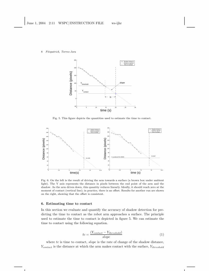
Fig. 5. This figure depicts the quantities used to estimate the time to contact.
0 2.5 5 7.5 10 12.50
20
40
60
80
100
120
140
160
180
200
time(s)
Dis
tanc
e (p
ixel
s)
54.1305
Shadow distanceDistance ajustedTime of contact
0 2.5 5 7.5 10 12.50
20
40
60
80
100
120
140
160
180
200
time (s)
Dis
tanc
e (p
ixel
s)
53.2667D. predicted=54.130500
Shadow distanceDistance ajustedTime of contact
Fig. 6. On the left is the result of driving the arm towards a surface (a brown box under ambientlight). The Y axis represents the distance in pixels between the end point of the arm and theshadow. As the arm drives down, this quantity reduces linearly. Ideally, it should reach zero at themoment of contact (vertical line); in practice, there is an offset. Results for another run are shownon the right, showing that the offset is consistent.
6. Estimating time to contact
In this section we evaluate and quantify the accuracy of shadow detection for pre-
dicting the time to contact as the robot arm approaches a surface. The principle
used to estimate the time to contact is depicted in figure 5. We can estimate the
time to contact using the following equation.
tc =(Ycontact − Ythreshold)
slope(1)
where tc is time to contact, slope is the rate of change of the shadow distance,
Ycontact is the distance at which the arm makes contact with the surface, Ythreshold
June 1, 2004 2:11 WSPC/INSTRUCTION FILE ws-ijhr
Using Cast Shadows for Visually-Guided Touching 9
0 1 2 3 4 5 6 7 820
40
60
80
100
120
140
160
time (s)
Dis
tanc
e (p
ixel
s)44.4222
D. predicted=43.000000
Shadow distanceDistance ajustedTime of contact
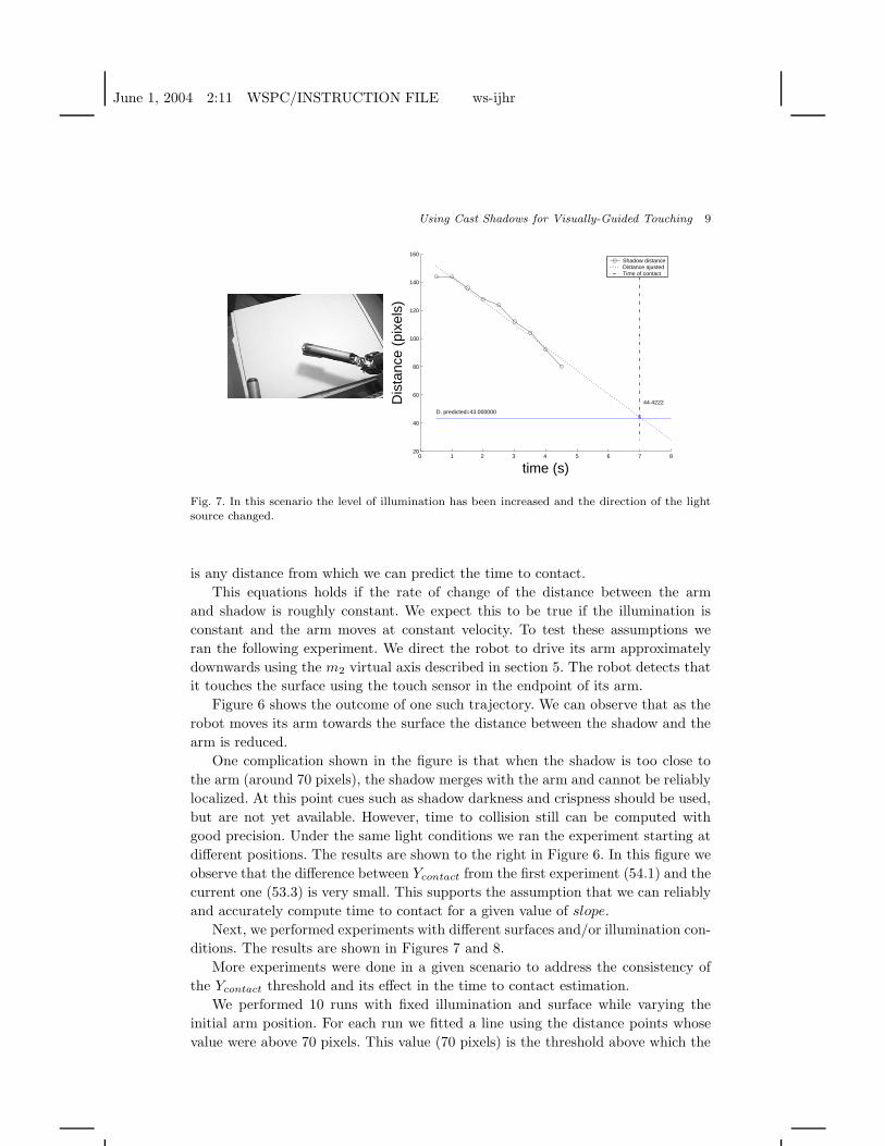
Fig. 7. In this scenario the level of illumination has been increased and the direction of the lightsource changed.
is any distance from which we can predict the time to contact.
This equations holds if the rate of change of the distance between the arm
and shadow is roughly constant. We expect this to be true if the illumination is
constant and the arm moves at constant velocity. To test these assumptions we
ran the following experiment. We direct the robot to drive its arm approximately
downwards using the m2 virtual axis described in section 5. The robot detects that
it touches the surface using the touch sensor in the endpoint of its arm.
Figure 6 shows the outcome of one such trajectory. We can observe that as the
robot moves its arm towards the surface the distance between the shadow and the
arm is reduced.
One complication shown in the figure is that when the shadow is too close to
the arm (around 70 pixels), the shadow merges with the arm and cannot be reliably
localized. At this point cues such as shadow darkness and crispness should be used,
but are not yet available. However, time to collision still can be computed with
good precision. Under the same light conditions we ran the experiment starting at
different positions. The results are shown to the right in Figure 6. In this figure we
observe that the difference between Ycontact from the first experiment (54.1) and the
current one (53.3) is very small. This supports the assumption that we can reliably
and accurately compute time to contact for a given value of slope.
Next, we performed experiments with different surfaces and/or illumination con-
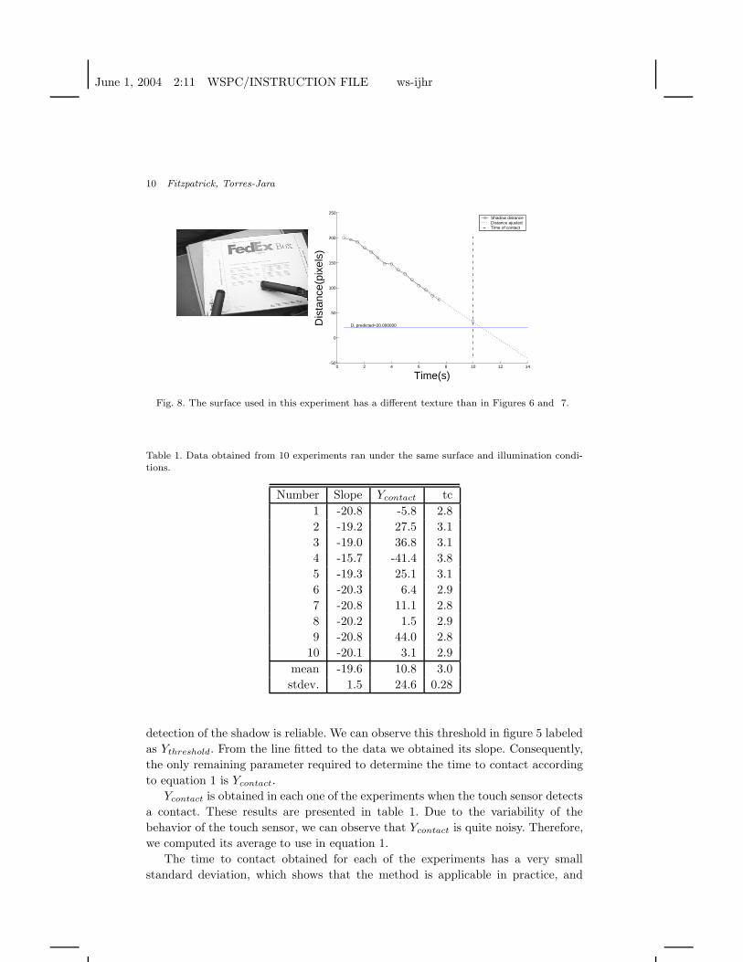
ditions. The results are shown in Figures 7 and 8.
More experiments were done in a given scenario to address the consistency of
the Ycontact threshold and its effect in the time to contact estimation.
We performed 10 runs with fixed illumination and surface while varying the
initial arm position. For each run we fitted a line using the distance points whose
value were above 70 pixels. This value (70 pixels) is the threshold above which the
June 1, 2004 2:11 WSPC/INSTRUCTION FILE ws-ijhr
10 Fitzpatrick, Torres-Jara
0 2 4 6 8 10 12 14−50
0
50
100
150
200
250
Time(s)
Dis
tanc
e(pi
xels
)D. predicted=20.000000
Shadow distanceDistance ajustedTime of contact
Fig. 8. The surface used in this experiment has a different texture than in Figures 6 and 7.
Table 1. Data obtained from 10 experiments ran under the same surface and illumination condi-tions.
Number Slope Ycontact tc
1 -20.8 -5.8 2.8
2 -19.2 27.5 3.1
3 -19.0 36.8 3.1
4 -15.7 -41.4 3.8
5 -19.3 25.1 3.1
6 -20.3 6.4 2.9
7 -20.8 11.1 2.8
8 -20.2 1.5 2.9
9 -20.8 44.0 2.8
10 -20.1 3.1 2.9
mean -19.6 10.8 3.0
stdev. 1.5 24.6 0.28
detection of the shadow is reliable. We can observe this threshold in figure 5 labeled
as Ythreshold. From the line fitted to the data we obtained its slope. Consequently,
the only remaining parameter required to determine the time to contact according
to equation 1 is Ycontact.
Ycontact is obtained in each one of the experiments when the touch sensor detects
a contact. These results are presented in table 1. Due to the variability of the
behavior of the touch sensor, we can observe that Ycontact is quite noisy. Therefore,
we computed its average to use in equation 1.
The time to contact obtained for each of the experiments has a very small
standard deviation, which shows that the method is applicable in practice, and
June 1, 2004 2:11 WSPC/INSTRUCTION FILE ws-ijhr
Using Cast Shadows for Visually-Guided Touching 11
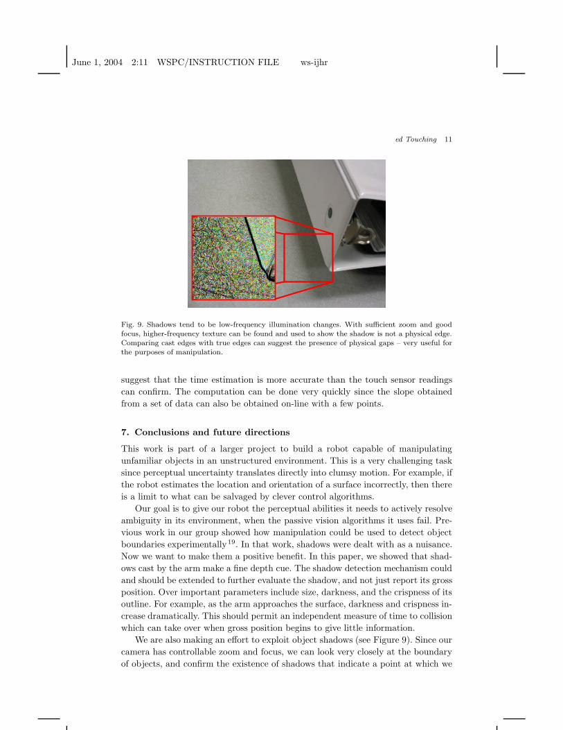
Fig. 9. Shadows tend to be low-frequency illumination changes. With sufficient zoom and goodfocus, higher-frequency texture can be found and used to show the shadow is not a physical edge.Comparing cast edges with true edges can suggest the presence of physical gaps – very useful forthe purposes of manipulation.
suggest that the time estimation is more accurate than the touch sensor readings
can confirm. The computation can be done very quickly since the slope obtained
from a set of data can also be obtained on-line with a few points.
7. Conclusions and future directions
This work is part of a larger project to build a robot capable of manipulating
unfamiliar objects in an unstructured environment. This is a very challenging task
since perceptual uncertainty translates directly into clumsy motion. For example, if
the robot estimates the location and orientation of a surface incorrectly, then there
is a limit to what can be salvaged by clever control algorithms.
Our goal is to give our robot the perceptual abilities it needs to actively resolve
ambiguity in its environment, when the passive vision algorithms it uses fail. Pre-
vious work in our group showed how manipulation could be used to detect object
boundaries experimentally19. In that work, shadows were dealt with as a nuisance.
Now we want to make them a positive benefit. In this paper, we showed that shad-
ows cast by the arm make a fine depth cue. The shadow detection mechanism could
and should be extended to further evaluate the shadow, and not just report its gross
position. Over important parameters include size, darkness, and the crispness of its
outline. For example, as the arm approaches the surface, darkness and crispness in-
crease dramatically. This should permit an independent measure of time to collision
which can take over when gross position begins to give little information.
We are also making an effort to exploit object shadows (see Figure 9). Since our
camera has controllable zoom and focus, we can look very closely at the boundary
of objects, and confirm the existence of shadows that indicate a point at which we
June 1, 2004 2:11 WSPC/INSTRUCTION FILE ws-ijhr
12 REFERENCES
might be able to lift the object.
Acknowledgements
This work was funded by DARPA DABT 63-00-C-10102 (“Natural Tasking of
Robots Based on Human Interaction Cues”), and by NTT under the NTT/MIT
Collaboration Agreement. The robot Coco was developed by Charles C. Kemp,
Chris Morse, Naoki Sadakuni, Eduardo Torres-Jara, and Juan Velasquez.
References
1. A. Prati, I. Mikic, M. M. Trivedi, R. Cucchiara, Detecting moving shadows: al-
gorithms and evaluation, IEEE Transactions on Pattern Analysis and Machine
Intelligence 25 (2003) (7) 918–923.
2. G. S. Hubona, G. Shirah, D. Jennings, The effects of cast shadows and stere-
opsis on performing computer-generated spatial tasks, IEEE Transactions on
Systems, Man and Cybernetics, Part A: Systems and Humans 34 (2004) (4)
forthcoming.
3. D. N. Lee, The optic flow field: the foundation of vision, Philosophical Trans-
actions of the Royal Society of London B 290 (1980) (1038) 169–179.
4. J. J. Gibson, The Ecological Approach to Visual Perception (Lawrence Erlbaum
Associates, Hillsdale, New Jersey, 1986).
5. C. J. Morse, Design of a quadruped walking robot for social interaction, Master’s
thesis, MIT Department of Electrical Engineering and Computer Science, Feb
2001.
6. G. S. Hubona, P. N. Wheeler, G. W. Shirah, M. Brandt, The relative contri-
butions of stereo, lighting, and background scenes in promoting 3D depth vi-
sualization, ACM Transactions on Computer-Human Interaction 6 (1999) (3)
214–242.
7. H. H. Hu, A. A. Gooch, W. B. Thompson, B. E. Smits, Visual cues for imminent
object contact in realistic virtual environments, in Proceedings of the 11th IEEE
Visualization Conference (Salt Lake City, Utah, 2000) .
8. H. H. Hu, A. A. Gooch, S. H. Creem-Regehr, W. B. Thompson, Visual cues
for perceiving distances from objects to surfaces, Presence: Teleoperators and
Virtual Environments 11 (2002) (6) 652–664.
9. D. Kersten, P. Mamassian, D. C. Knill, Moving cast shadows induce apparent
motion in depth, Perception 26 (1997) (2) 171–192.
10. P. Mamassian, D. C. Knill, D. Kersten, The perception of cast shadows, Trends
in Cognitive Sciences 2 (1998) (8) 288–295.
11. D. Kersten, D. C. Knill, P. Mamassian, I. Bulthoff, Illusory motion from shad-
ows, Nature 379 (1996) (6560) 31.
12. L. R. Wanger, J. A. Ferwerda, D. P. Greenberg, Perceiving spatial relationships
in computer-generated images, IEEE Computer Graphics and Applications 12
(1992) (3) 44–58.
June 1, 2004 2:11 WSPC/INSTRUCTION FILE ws-ijhr
REFERENCES 13
13. W. B. Thompson, P. Shirley, B. Smits, D. J. Kersten, C. Madison, Visual glue,
Tech. Rep. UUCS-98-007, University of Utah, March 1998.
14. F. Pavani, U. Castiello, Binding personal and extrapersonal space through body
shadows, Nature Neuroscience 7 (2004) (1) 14–15.
15. U. Castiello, D. Lusher, C. Burton, P. Disler, Shadows in the brain, Journal of
Cognitive Neuroscience 15 (2003) (6) 862–872.
16. J. Stauder, R. Mech, J. Ostermann, Detection of moving cast shadows for object
segmentation, IEEE Transactions on Multimedia 1 (1999) (1) 65–76.
17. J. Bouguet, P. Perona, 3D photography using shadows in dual-space geometry,
International Journal of Computer Vision 35 (1999) (2) 129–149.
18. A. M. Bruckstein, R. J. Holt, Y. D. Jean, A. N. Netravali, On the use of shadows
in stance recovery, International Journal of Imaging Systems and Technology
11 (2001) (5) 315–330.
19. P. Fitzpatrick, G. Metta, Grounding vision through experimental manipulation,
Philosophical Transactions of the Royal Society: Mathematical, Physical, and
Engineering Sciences 361 (2003) (1811) 2165–2185.
Paul M. Fitzpatrick is currently a Postdoctoral Lecturer at
the MIT Computer Science and Artificial Intelligence Labora-
tory. He receive his M.Eng. in Computer Engineering from the
University of Limerick, Ireland, and a Ph.D. in Computer Sci-
ence from MIT in June 2003 for work addressing developmental
approaches to machine perception for a humanoid robot.
Eduardo Torres-Jara received his B.S. degree in Electrical
Engineering from Escuela Politecnica del Ejercito, Ecuador, and
his M.S. from MIT in Electrical Engineering and Computer Sci-
ence. He is currently a Ph.D. candidate at MIT CSAIL. He is a
member of the IEEE society.


![TRANSPARENT LUMINOUS/ OBJECT NON-LUMINOUS AIR, …...4. [opaque/transparent] objects cast shadows. 5. Coloured objects form [coloured / dark] shadows. III) Define : 1. Opaque objects](https://img.pdfslide.us/doc/110x75/5f1dcaf7170ea179f76e1653/transparent-luminous-object-non-luminous-air-4-opaquetransparent-objects.jpg)