Embed Size (px)
Citation preview
ORIGINAL PAPER
A methodology for creating a statistically derived shape grammarcomposed of non-obvious shape chunks
Seth Orsborn Æ Jonathan Cagan Æ Peter Boatwright
Received: 1 September 2006 / Accepted: 29 May 2007 / Published online: 9 October 2007
� Springer-Verlag London Limited 2007
Abstract A shape grammar is a production system that can
be used to create new product designs. Traditionally, a
product shape grammar’s rules are created by a skilled per-
son that understands the language of the design. In this paper
the results of a principal component analysis of vehicles are
used to create a vehicle shape grammar by basing the rules
upon the determined shape relationships. The advantages are
that: rules can be created according the results of a statistical
analysis, and not according to a designer’s subjective
observations; class specific vehicles can be created with
fewer rule applications; and those rule applications encour-
age divergent designs. Using the principal component
analysis based shape grammar, unique vehicles are created
to demonstrate the potential of statistically based concept
creation for the generation of product forms.
Keywords Vehicle design � Design language �Principal component analysis � Shape grammar
1 Introduction
Vehicle designers have many tools at their disposal to help
them in the creation of new vehicle concepts. Brands have
established design languages that can be referenced on
style sheets. Designers are trained to use their skill and
intuition to bring potential designs to reality while
respecting the established brand history and features for a
product class. The understanding of vehicle differentiations
is often based upon a general understanding of the vehicle
form and established relationships between vehicle char-
acteristics. This paper takes the results of a statistical
analysis of vehicle forms as the design vocabulary for three
vehicle classes. This vocabulary is then used as the basis
for a vehicle shape grammar.
Shape grammars have been used as a computational
design tool for representing design artifacts for over two
decades. Shape grammars are a production system created
by taking a sample of the whole for which one is trying to
write a language (Stiny 1980). From this sample a
vocabulary of shapes can be written that represent all the
basic forms of that sample. By defining the spatial rela-
tionships between those forms and how the forms are
related to each other, shape rules can be written. A shape
rule consists of a left and right side. If the shape in the left
side matches a shape in a drawing then the rule can be
applied, and the matching shape changes to match the right
side of the rule. The shape rules allow the addition and
subtraction of shapes, which in the end are perceived as
shape modifications. These shape rules, combined with an
initial shape, produce a shape grammar that represents the
language of the design (Stiny 1980). Shapes themselves
can exist as points, lines, planes, volumes, or any combi-
nation thereof (Stiny 1980). All shape generation must
start with an initial shape: a point, a coordinate axis, or
some foundation from which to start the shape grammar. If
the grammar is going to end, it can end with a terminal
rule, which prevents any other rules from being applied
after it. This forces there to be closure in the rule
sequence. Alternatively, a design sequence can continue
S. Orsborn � J. Cagan (&)
Department of Mechanical Engineering,
Carnegie Mellon University, Scaife Hall,
5000 Forbes Avenue, Pittsburgh,
PA 15213, USA
e-mail: [email protected]
P. Boatwright
Tepper School of Business, Carnegie Mellon University,
Pittsburgh, PA, USA
123
Res Eng Design (2008) 18:181–196
DOI 10.1007/s00163-007-0035-9
indefinitely and designs could be chosen at any point in the
design process.
The method introduced here fundamentally changes the
method of developing the shape grammar. Previously, the
vocabulary of the design to be used as the foundation of
the shape grammar was determined by the creator of the
grammar. The creator of the grammar would look at the
sample and subjectively derive the vocabulary. From that
vocabulary, the rules would be formed based upon the
creator’s experience and intention. It is quite possible that
two different persons looking at the same sample of shapes
would create two very different shape grammars. In this
work we introduce a method that uses a statistical analysis
of product characteristics to determine relevant groupings
of elements. These objective groupings are then used to
create rules for the shape grammar.
Orsborn et al. (2006) developed a vehicle shape gram-
mar based upon the existing vehicle classes of coupe,
pickup, and SUV. It was determined, in conjunction with a
vehicle designer, which vehicle characteristics were most
important for capturing the general form of the vehicle so
that a potential consumer would recognize different vehi-
cles. The forms for 15 coupes, 20 SUVs, and seven pickups
were captured using four-control-point Bezier curves. The
data collected from this sample was statistically analyzed
in Orsborn et al. (2007). Principal component analysis was
used to determine the fundamental characteristics within
the individual vehicle classes of coupe, pickup, and SUV.
Principal component analysis is a statistical method
whereby an original set of related data is reduced in
dimensionality to match the original data as closely as
possible (Patel et al. 2006). Principal component analysis
finds a set of new variables that are weighted averages of
the original variables. The first principal component is a
vector that captures most of the variation between the
original variables. Each variable is then given a weight
related to the vector. The weight describes the influence of
that variable on the principal component. Based upon the
weights of all the variables a percentage variance explained
is calculated for the first principal component. The second
principal component is described using a vector orthogonal
to the first principal component. The analysis is repeated,
returning different weights for the variables and a smaller
percentage variance explained. In many applications, like
vehicles, only a few principal components account for
much of the differences in the objects and identify key
elements that distinguish the objects.
The fundamental characteristics found through the prin-
cipal component analysis of the vehicles at times differed
from the traditional and expected feature definition, resulting
in a deeper understanding of what features of an existing set
of designs must differentiate one form from another (Orsborn
et al. 2007). In this paper, the results from the principal
component analysis are used to create a new shape grammar
based upon these discovered shape relationships. The shape
grammar is then used to create new vehicles. Although the
focus of this paper is on vehicle design, the methods devel-
oped here are applicable to any class of physical products
based on a consistent form language.
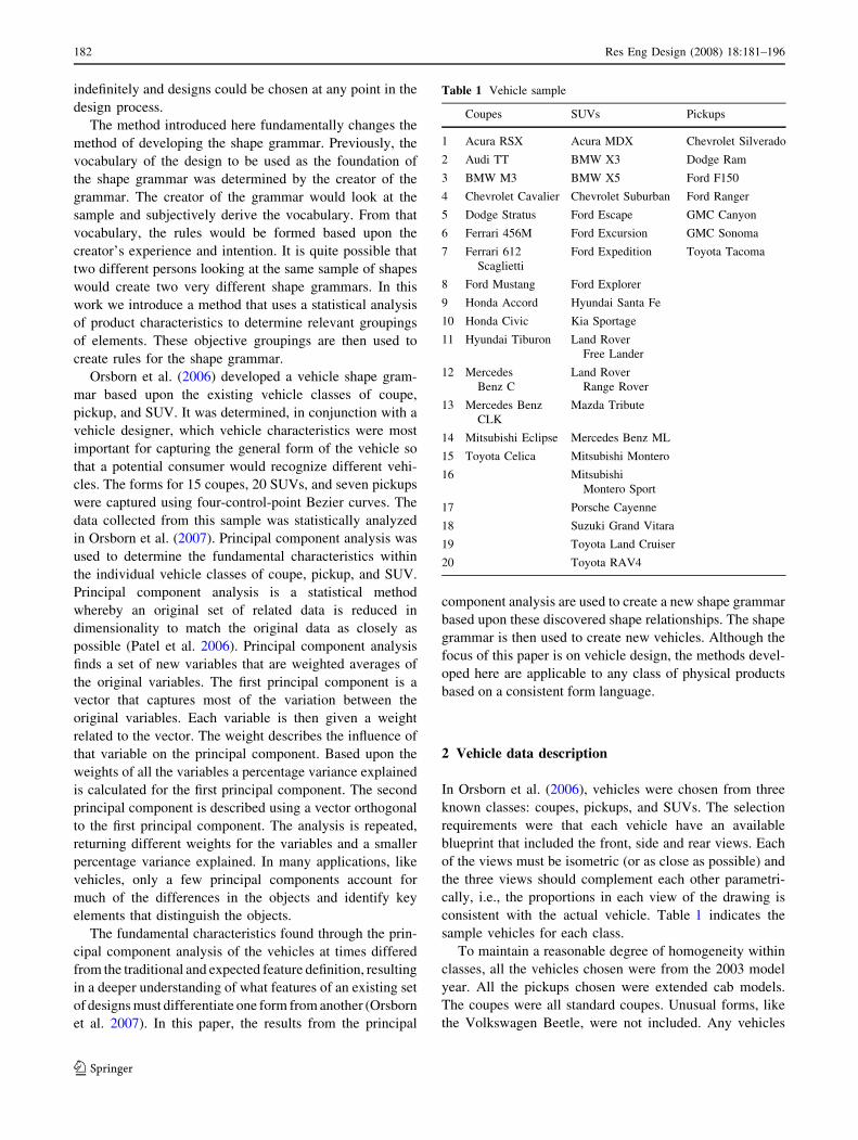
2 Vehicle data description
In Orsborn et al. (2006), vehicles were chosen from three
known classes: coupes, pickups, and SUVs. The selection
requirements were that each vehicle have an available
blueprint that included the front, side and rear views. Each
of the views must be isometric (or as close as possible) and
the three views should complement each other parametri-
cally, i.e., the proportions in each view of the drawing is
consistent with the actual vehicle. Table 1 indicates the
sample vehicles for each class.
To maintain a reasonable degree of homogeneity within
classes, all the vehicles chosen were from the 2003 model
year. All the pickups chosen were extended cab models.
The coupes were all standard coupes. Unusual forms, like
the Volkswagen Beetle, were not included. Any vehicles
Table 1 Vehicle sample
Coupes SUVs Pickups
1 Acura RSX Acura MDX Chevrolet Silverado
2 Audi TT BMW X3 Dodge Ram
3 BMW M3 BMW X5 Ford F150
4 Chevrolet Cavalier Chevrolet Suburban Ford Ranger
5 Dodge Stratus Ford Escape GMC Canyon
6 Ferrari 456M Ford Excursion GMC Sonoma
7 Ferrari 612
Scaglietti
Ford Expedition Toyota Tacoma
8 Ford Mustang Ford Explorer
9 Honda Accord Hyundai Santa Fe
10 Honda Civic Kia Sportage
11 Hyundai Tiburon Land Rover
Free Lander
12 Mercedes
Benz C
Land Rover
Range Rover
13 Mercedes Benz
CLK
Mazda Tribute
14 Mitsubishi Eclipse Mercedes Benz ML
15 Toyota Celica Mitsubishi Montero
16 Mitsubishi
Montero Sport
17 Porsche Cayenne
18 Suzuki Grand Vitara
19 Toyota Land Cruiser
20 Toyota RAV4
182 Res Eng Design (2008) 18:181–196
123
considered to be anomalies in their class were not chosen.
For example, the Infiniti FX35, while technically an SUV,
has an unusual form with respect to most SUVs (Csere
2003). This vehicle was not included in the sample.
The intention of this paper is to apply our understanding
of the foundational forms in vehicle classes through the
creation and application of a vehicle shape grammar. The
vehicle characteristics from Orsborn et al. (2006) were
used, and will be discussed in detail in this section.
Through discussion with a vehicle designer, it was deter-
mined that the following vehicle characteristics are the
most relevant for sufficiently describing the form of the
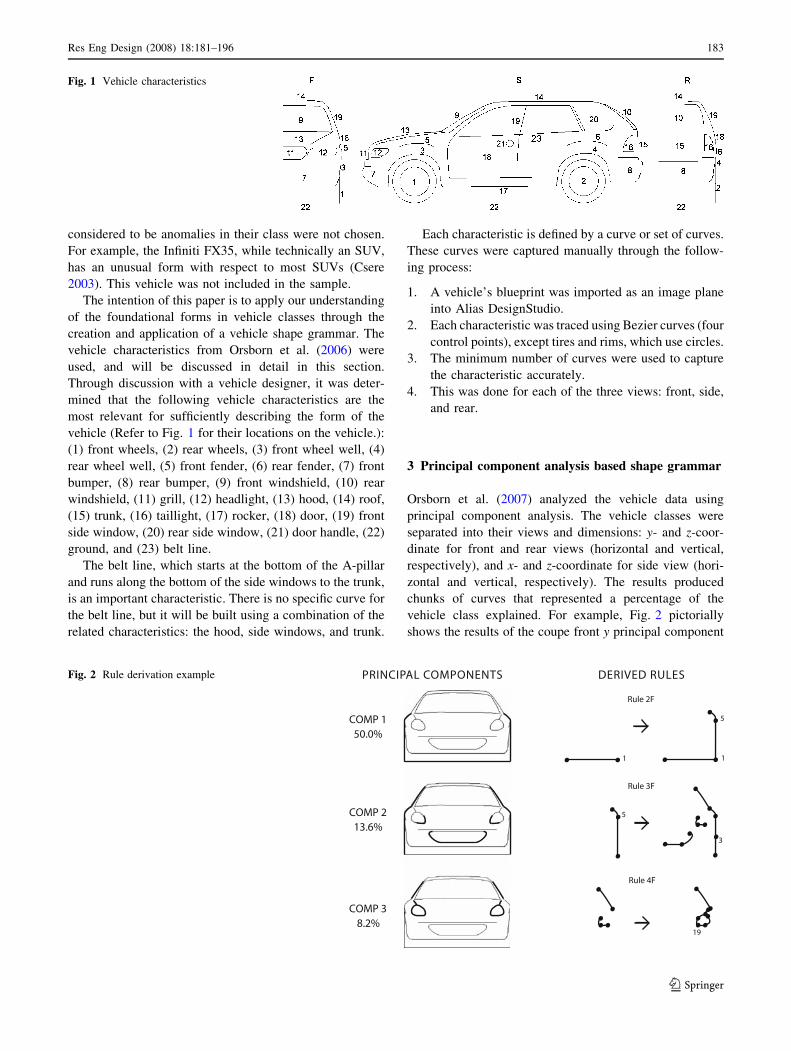
vehicle (Refer to Fig. 1 for their locations on the vehicle.):
(1) front wheels, (2) rear wheels, (3) front wheel well, (4)
rear wheel well, (5) front fender, (6) rear fender, (7) front
bumper, (8) rear bumper, (9) front windshield, (10) rear
windshield, (11) grill, (12) headlight, (13) hood, (14) roof,
(15) trunk, (16) taillight, (17) rocker, (18) door, (19) front
side window, (20) rear side window, (21) door handle, (22)
ground, and (23) belt line.
The belt line, which starts at the bottom of the A-pillar
and runs along the bottom of the side windows to the trunk,
is an important characteristic. There is no specific curve for
the belt line, but it will be built using a combination of the
related characteristics: the hood, side windows, and trunk.
Each characteristic is defined by a curve or set of curves.
These curves were captured manually through the follow-
ing process:
1. A vehicle’s blueprint was imported as an image plane
into Alias DesignStudio.
2. Each characteristic was traced using Bezier curves (four
control points), except tires and rims, which use circles.
3. The minimum number of curves were used to capture
the characteristic accurately.
4. This was done for each of the three views: front, side,
and rear.
3 Principal component analysis based shape grammar
Orsborn et al. (2007) analyzed the vehicle data using
principal component analysis. The vehicle classes were
separated into their views and dimensions: y- and z-coor-
dinate for front and rear views (horizontal and vertical,
respectively), and x- and z-coordinate for side view (hori-
zontal and vertical, respectively). The results produced
chunks of curves that represented a percentage of the
vehicle class explained. For example, Fig. 2 pictorially
shows the results of the coupe front y principal component
Fig. 1 Vehicle characteristics
Fig. 2 Rule derivation example
Res Eng Design (2008) 18:181–196 183
123
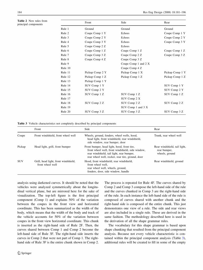
analysis using darkened curves. It should be noted that the
vehicles were analyzed symmetrically about the longitu-
dinal vertical plane, but are mirrored here for the sake of
visualization. The top-left figure is the first principal
component (Comp 1) and explains 50% of the variation
between the coupes in the front view and horizontal
coordinate. This has been summarized as the width of the
body, which means that the width of the body and track of
the vehicle accounts for 50% of the variation between
coupes in the front view horizontal coordinate. This chunk
is inserted as the right-hand side of Rule 2F. Then, the
curves shared between Comp 1 and Comp 2 become the
left-hand side of Rule 3F. The right-hand side inserts the
curves in Comp 2 that were not part of Comp 1. The right-
hand side of Rule 3F is the entire chunk shown in Comp 2.
The process is repeated for Rule 4F. The curves shared by
Comp 2 and Comp 3 compose the left-hand side of the rule
and the curves chunked in Comp 3 are the right-hand side
of the rule. In each instance the left-hand side of the rule is
composed of curves shared with another chunk and the
right-hand side is composed of the entire chunk. This just
demonstrates one view of a rule. The side and rear views
are also included in a single rule. These are derived in the
same fashion. The methodology described here is used in
the derivation of all the shape grammar rules.
The vocabulary for this shape grammar is based upon
shape chunking that resulted from the principal component
analysis. Because not every vehicle characteristic is con-
tained within the principal component analysis (Table 3),
additional rules will be created to fill in some of the empty
Table 2 New rules from
principal componentsFront Side Rear
Rule 1 Ground Ground Ground
Rule 2 Coupe Comp 1 Y Echoes Coupe Comp 1 Y
Rule 3 Coupe Comp 2 Y Echoes Coupe Comp 2 Y
Rule 4 Coupe Comp 3 Y Echoes Coupe Comp 3 Y
Rule 5 Coupe Comp 2 Z Echoes
Rule 6 Coupe Comp 1 Z Coupe Comp 1 Z Coupe Comp 1 Z
Rule 7 Coupe Comp 3 Z Coupe Comp 2 Z Coupe Comp 3 Z
Rule 8 Coupe Comp 4 Z Coupe Comp 3 Z
Rule 9 Coupe Comp 1 and 2 X
Rule 10 Coupe Comp 4 Z
Rule 11 Pickup Comp 2 Y Pickup Comp 1 X Pickup Comp 1 Y
Rule 12 Pickup Comp 1 Z Pickup Comp 1 Z Pickup Comp 1 Z
Rule 13 Pickup Comp 1 Y
Rule 14 SUV Comp 1 Y SUV Comp 1 Y
Rule 15 SUV Comp 2 Y SUV Comp 2 Y
Rule 16 SUV Comp 1 Z SUV Comp 1 Z SUV Comp 1 Z
Rule 17 SUV Comp 2 X
Rule 18 SUV Comp 2 Z SUV Comp 2 Z SUV Comp 2 Z
Rule 19 SUV Comp 1 and 3 X
Rule 20 SUV Comp 3 Z SUV Comp 3 Z SUV Comp 3 Z
Table 3 Vehicle characteristics not completely described by principal components
Front Side Rear
Coupe Front windshield, front wheel well Wheels, ground, fenders, wheel wells, hood,
head light, front windshield, rear windshield,
side window, rear bumper, door
Trunk, rear wheel well
Pickup Head light, grill, front bumper Front bumper, head light, hood, front tire,
front wheel well, front windshield, side window,
rear windshield, tail light, rear bumper,
rear wheel well, rocker, rear tire, ground, door
Rear windshield, tail light,
rear bumper,
wheels, ground
SUV Grill, head light, front windshield,
front wheel well
Hood, front windshield, rear windshield,
front wheel well,
rear wheel well, wheels, ground,
fenders, door, side window, handle
Rear windshield, ground
184 Res Eng Design (2008) 18:181–196
123
spaces. This new shape grammar will be compared and
contrasted with the original vehicle shape grammar from
Orsborn et al. (2006).
The shape grammar rules use labels and makers. The
markers (a dot) indicate the end of a four-control-point
Bezier curve. The labels (a number) guide the rule appli-
cation. While the intention of many shape grammars is to
be elegant, the emphasis here is to show that shape
grammar rules can be objectively derived from a principal
component analysis. Table 2 lists the 20 shape grammar
rules and their principal component composition. It should
be noted that the groupings of the principal components
provided a connected progression through the rules. By
selecting principal components with related curves, a
sequence was automatically created that maintained the
shape relationships found through the principal component
analysis. In most instances, the dominant principal com-
ponents came earlier in the rule progression. There are
some principal components that are not used in rules. This
is because the curves that are chunked together already
appear in another principal component. In the instance
where one principal component shares all of its curves with
another, the principal component is used which simplifies
the rule progression. The rules are separated according the
vehicle class, since this is how the vehicles were analyzed.
We introduce the term echo in Table 2. An echo is when a
certain shape is indicated in the front and rear views but not
in the side view of the principal component analysis. The
shape is ‘‘echoed’’ into the side view of the rule, for the
sake of continuity.
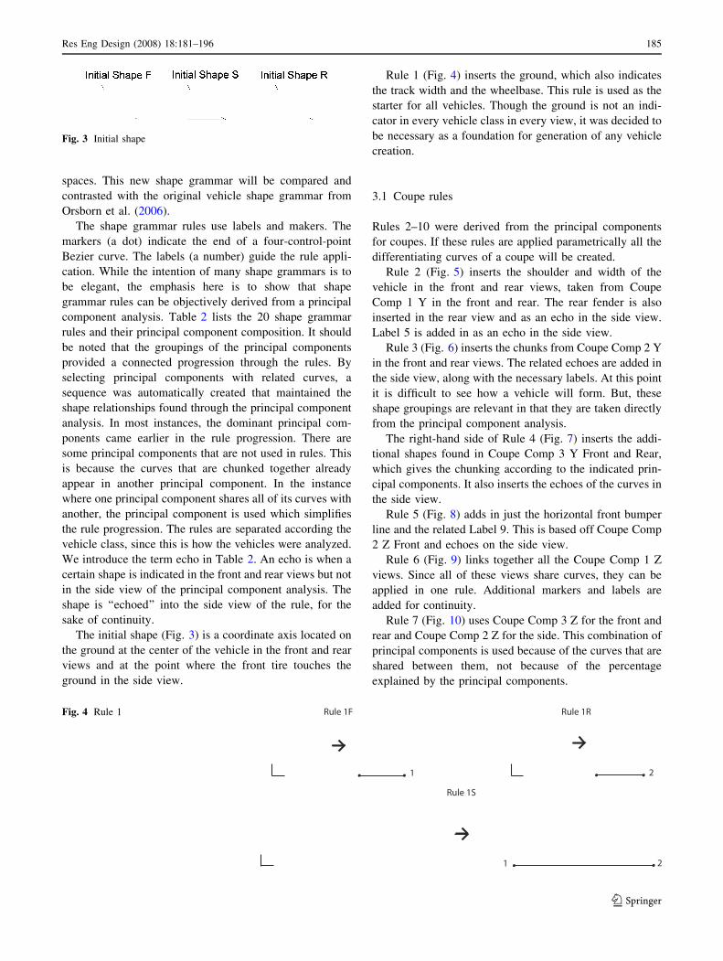
The initial shape (Fig. 3) is a coordinate axis located on
the ground at the center of the vehicle in the front and rear
views and at the point where the front tire touches the
ground in the side view.
Rule 1 (Fig. 4) inserts the ground, which also indicates
the track width and the wheelbase. This rule is used as the
starter for all vehicles. Though the ground is not an indi-
cator in every vehicle class in every view, it was decided to
be necessary as a foundation for generation of any vehicle
creation.
3.1 Coupe rules
Rules 2–10 were derived from the principal components
for coupes. If these rules are applied parametrically all the
differentiating curves of a coupe will be created.
Rule 2 (Fig. 5) inserts the shoulder and width of the
vehicle in the front and rear views, taken from Coupe
Comp 1 Y in the front and rear. The rear fender is also
inserted in the rear view and as an echo in the side view.
Label 5 is added in as an echo in the side view.
Rule 3 (Fig. 6) inserts the chunks from Coupe Comp 2 Y
in the front and rear views. The related echoes are added in
the side view, along with the necessary labels. At this point
it is difficult to see how a vehicle will form. But, these
shape groupings are relevant in that they are taken directly
from the principal component analysis.
The right-hand side of Rule 4 (Fig. 7) inserts the addi-
tional shapes found in Coupe Comp 3 Y Front and Rear,
which gives the chunking according to the indicated prin-
cipal components. It also inserts the echoes of the curves in
the side view.
Rule 5 (Fig. 8) adds in just the horizontal front bumper
line and the related Label 9. This is based off Coupe Comp
2 Z Front and echoes on the side view.
Rule 6 (Fig. 9) links together all the Coupe Comp 1 Z
views. Since all of these views share curves, they can be
applied in one rule. Additional markers and labels are
added for continuity.
Rule 7 (Fig. 10) uses Coupe Comp 3 Z for the front and
rear and Coupe Comp 2 Z for the side. This combination of
principal components is used because of the curves that are
shared between them, not because of the percentage
explained by the principal components.
Fig. 3 Initial shape
Fig. 4 Rule 1
Res Eng Design (2008) 18:181–196 185
123
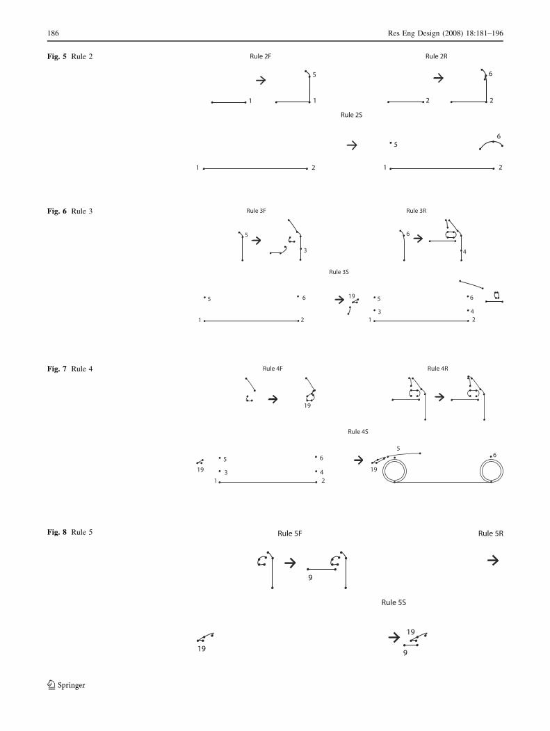
Fig. 5 Rule 2
Fig. 6 Rule 3
Fig. 7 Rule 4
Rule 5F
Rule 5S
Rule 5R
9
19
19
9
Fig. 8 Rule 5
186 Res Eng Design (2008) 18:181–196
123
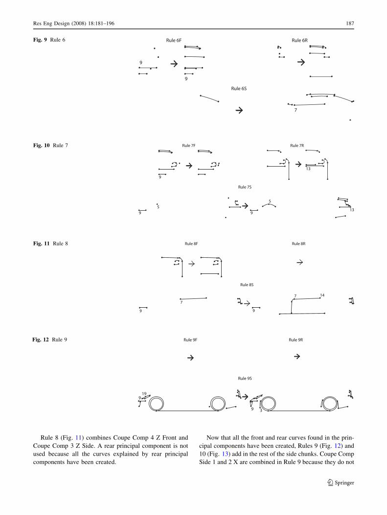
Rule 8 (Fig. 11) combines Coupe Comp 4 Z Front and
Coupe Comp 3 Z Side. A rear principal component is not
used because all the curves explained by rear principal
components have been created.
Now that all the front and rear curves found in the prin-
cipal components have been created, Rules 9 (Fig. 12) and
10 (Fig. 13) add in the rest of the side chunks. Coupe Comp
Side 1 and 2 X are combined in Rule 9 because they do not
Rule 6F
Rule 6S
Rule 6R
9
9
7
Fig. 9 Rule 6
9
Rule 7F
Rule 7S
Rule 7R
5
9 9
5
13
13
Fig. 10 Rule 7
Rule 8F
Rule 8S
Rule 8R
9
7
9
7 14
Fig. 11 Rule 8
Rule 9F
Rule 9S
Rule 9R
199
9 3
Fig. 12 Rule 9
Res Eng Design (2008) 18:181–196 187
123
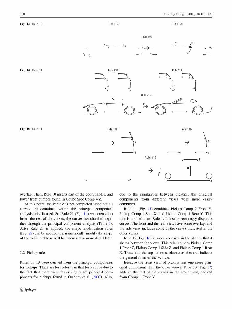
overlap. Then, Rule 10 inserts part of the door, handle, and
lower front bumper found in Coupe Side Comp 4 Z.
At this point, the vehicle is not completed since not all
curves are contained within the principal component
analysis criteria used. So, Rule 21 (Fig. 14) was created to
insert the rest of the curves, the curves not chunked toge-
ther through the principal component analysis (Table 3).
After Rule 21 is applied, the shape modification rules
(Fig. 27) can be applied to parametrically modify the shape
of the vehicle. These will be discussed in more detail later.
3.2 Pickup rules
Rules 11–13 were derived from the principal components
for pickups. There are less rules than that for a coupe due to
the fact that there were fewer significant principal com-
ponents for pickups found in Orsborn et al. (2007). Also,
due to the similarities between pickups, the principal
components from different views were more easily
combined.
Rule 11 (Fig. 15) combines Pickup Comp 2 Front Y,
Pickup Comp 1 Side X, and Pickup Comp 1 Rear Y. This
rule is applied after Rule 1. It inserts seemingly disparate
curves. The front and the rear view have some overlap, and
the side view includes some of the curves indicated in the
other views.
Rule 12 (Fig. 16) is more cohesive in the shapes that it
shares between the views. This rule includes Pickup Comp
1 Front Z, Pickup Comp 1 Side Z, and Pickup Comp 1 Rear
Z. These add the tops of most characteristics and indicate
the general form of the vehicle.
Because the front view of pickups has one more prin-
cipal component than the other views, Rule 13 (Fig. 17)
adds in the rest of the curves in the front view, derived
from Comp 1 Front Y.
Fig. 13 Rule 10
Rule 21F
Rule 21S
Rule 21R
7 14 13
4
2
3
1
Fig. 14 Rule 21
Rule 11F
Rule 11S
Rule 11R
1 1
5
2 2
6
1 2 1 2
11
Fig. 15 Rule 11
188 Res Eng Design (2008) 18:181–196
123
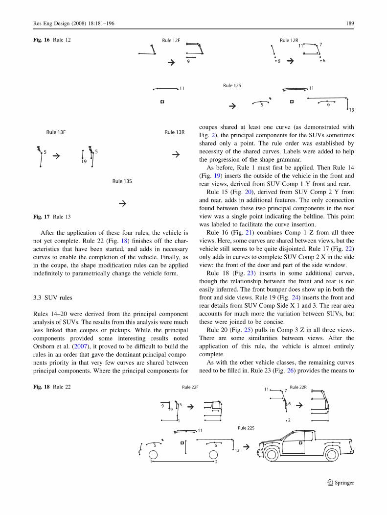
After the application of these four rules, the vehicle is
not yet complete. Rule 22 (Fig. 18) finishes off the char-
acteristics that have been started, and adds in necessary
curves to enable the completion of the vehicle. Finally, as
in the coupe, the shape modification rules can be applied
indefinitely to parametrically change the vehicle form.
3.3 SUV rules
Rules 14–20 were derived from the principal component
analysis of SUVs. The results from this analysis were much
less linked than coupes or pickups. While the principal
components provided some interesting results noted
Orsborn et al. (2007), it proved to be difficult to build the
rules in an order that gave the dominant principal compo-
nents priority in that very few curves are shared between
principal components. Where the principal components for
coupes shared at least one curve (as demonstrated with
Fig. 2), the principal components for the SUVs sometimes
shared only a point. The rule order was established by
necessity of the shared curves. Labels were added to help
the progression of the shape grammar.
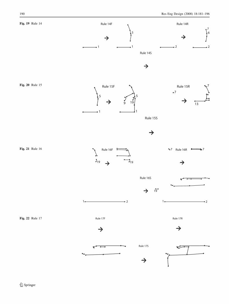
As before, Rule 1 must first be applied. Then Rule 14
(Fig. 19) inserts the outside of the vehicle in the front and
rear views, derived from SUV Comp 1 Y front and rear.
Rule 15 (Fig. 20), derived from SUV Comp 2 Y front
and rear, adds in additional features. The only connection
found between these two principal components in the rear
view was a single point indicating the beltline. This point
was labeled to facilitate the curve insertion.
Rule 16 (Fig. 21) combines Comp 1 Z from all three
views. Here, some curves are shared between views, but the
vehicle still seems to be quite disjointed. Rule 17 (Fig. 22)
only adds in curves to complete SUV Comp 2 X in the side
view: the front of the door and part of the side window.
Rule 18 (Fig. 23) inserts in some additional curves,
though the relationship between the front and rear is not
easily inferred. The front bumper does show up in both the
front and side views. Rule 19 (Fig. 24) inserts the front and
rear details from SUV Comp Side X 1 and 3. The rear area
accounts for much more the variation between SUVs, but
these were joined to be concise.
Rule 20 (Fig. 25) pulls in Comp 3 Z in all three views.
There are some similarities between views. After the
application of this rule, the vehicle is almost entirely
complete.
As with the other vehicle classes, the remaining curves
need to be filled in. Rule 23 (Fig. 26) provides the means to
6
Rule 12F
Rule 12S
Rule 12R
9
11
6 6
5
11
13
11 7Fig. 16 Rule 12
Rule 13F
Rule 13S
Rule 13R
5 5
19
Fig. 17 Rule 13
Rule 22F
Rule 22S
Rule 22R
1
5 6
1
919
11 7
5
11
613
2
2
Fig. 18 Rule 22
Res Eng Design (2008) 18:181–196 189
123
Rule 14F
Rule 14S
Rule 14R
1
5
1 2 2
67
Fig. 19 Rule 14
Rule 15F
Rule 15S
Rule 15R
5
1
5
1
9 19
7
7
13
Fig. 20 Rule 15
Rule 16F
Rule 16S
Rule 16R
19 19
1 2 1 2
19
7 7Fig. 21 Rule 16
Rule 17F
Rule 17S
Rule 17RFig. 22 Rule 17
190 Res Eng Design (2008) 18:181–196
123
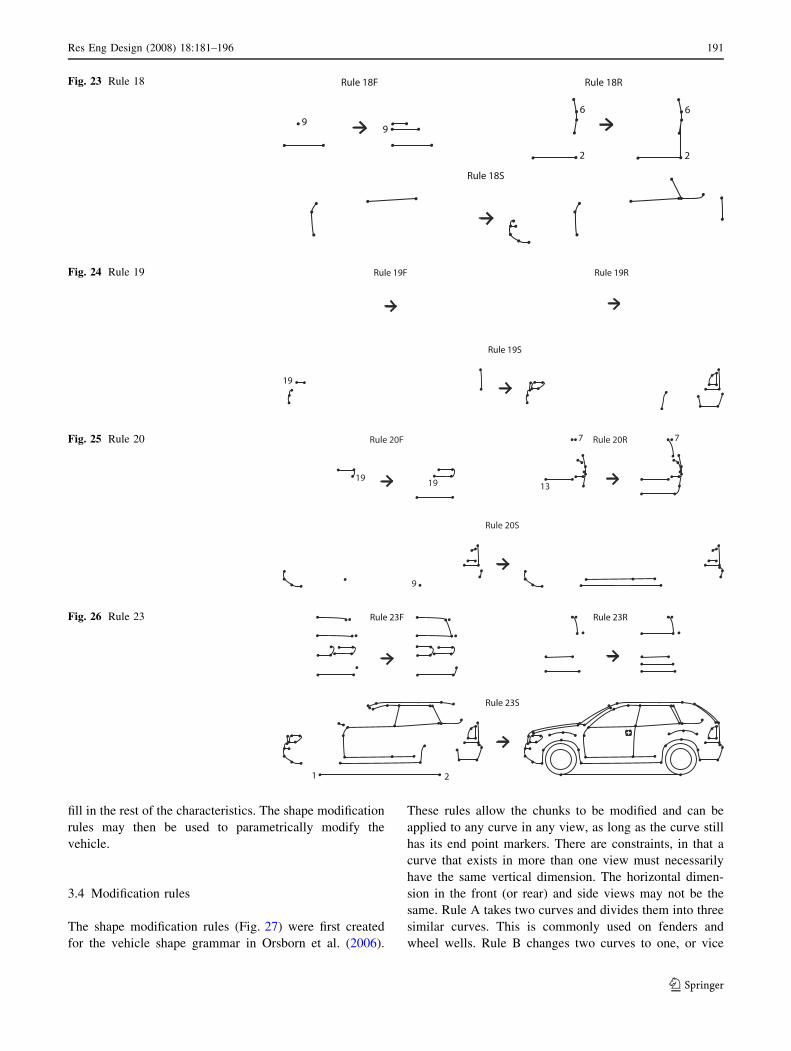
fill in the rest of the characteristics. The shape modification
rules may then be used to parametrically modify the
vehicle.
3.4 Modification rules
The shape modification rules (Fig. 27) were first created
for the vehicle shape grammar in Orsborn et al. (2006).
These rules allow the chunks to be modified and can be
applied to any curve in any view, as long as the curve still
has its end point markers. There are constraints, in that a
curve that exists in more than one view must necessarily
have the same vertical dimension. The horizontal dimen-
sion in the front (or rear) and side views may not be the
same. Rule A takes two curves and divides them into three
similar curves. This is commonly used on fenders and
wheel wells. Rule B changes two curves to one, or vice
Rule 18F
Rule 18S
Rule 18R
99
6
2
6
2
Fig. 23 Rule 18
Rule 19F
Rule 19S
Rule 19R
19
Fig. 24 Rule 19
Fig. 25 Rule 20
Rule 23F
Rule 23S
Rule 23R
1 2
Fig. 26 Rule 23
Res Eng Design (2008) 18:181–196 191
123
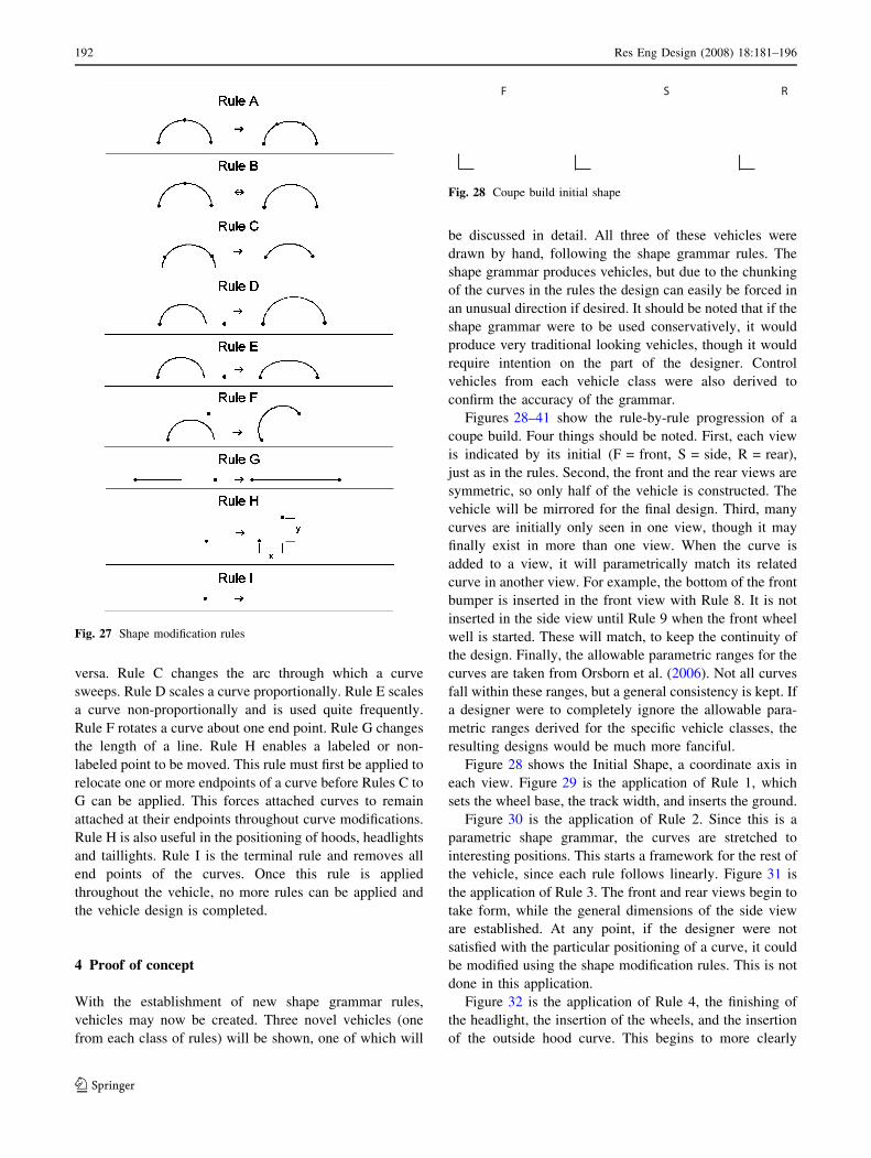
versa. Rule C changes the arc through which a curve
sweeps. Rule D scales a curve proportionally. Rule E scales
a curve non-proportionally and is used quite frequently.
Rule F rotates a curve about one end point. Rule G changes
the length of a line. Rule H enables a labeled or non-
labeled point to be moved. This rule must first be applied to
relocate one or more endpoints of a curve before Rules C to
G can be applied. This forces attached curves to remain
attached at their endpoints throughout curve modifications.
Rule H is also useful in the positioning of hoods, headlights
and taillights. Rule I is the terminal rule and removes all
end points of the curves. Once this rule is applied
throughout the vehicle, no more rules can be applied and
the vehicle design is completed.
4 Proof of concept
With the establishment of new shape grammar rules,
vehicles may now be created. Three novel vehicles (one
from each class of rules) will be shown, one of which will
be discussed in detail. All three of these vehicles were
drawn by hand, following the shape grammar rules. The
shape grammar produces vehicles, but due to the chunking
of the curves in the rules the design can easily be forced in
an unusual direction if desired. It should be noted that if the
shape grammar were to be used conservatively, it would
produce very traditional looking vehicles, though it would
require intention on the part of the designer. Control
vehicles from each vehicle class were also derived to
confirm the accuracy of the grammar.
Figures 28–41 show the rule-by-rule progression of a
coupe build. Four things should be noted. First, each view
is indicated by its initial (F = front, S = side, R = rear),
just as in the rules. Second, the front and the rear views are
symmetric, so only half of the vehicle is constructed. The
vehicle will be mirrored for the final design. Third, many
curves are initially only seen in one view, though it may
finally exist in more than one view. When the curve is
added to a view, it will parametrically match its related
curve in another view. For example, the bottom of the front
bumper is inserted in the front view with Rule 8. It is not
inserted in the side view until Rule 9 when the front wheel
well is started. These will match, to keep the continuity of
the design. Finally, the allowable parametric ranges for the
curves are taken from Orsborn et al. (2006). Not all curves
fall within these ranges, but a general consistency is kept. If
a designer were to completely ignore the allowable para-
metric ranges derived for the specific vehicle classes, the
resulting designs would be much more fanciful.
Figure 28 shows the Initial Shape, a coordinate axis in
each view. Figure 29 is the application of Rule 1, which
sets the wheel base, the track width, and inserts the ground.
Figure 30 is the application of Rule 2. Since this is a
parametric shape grammar, the curves are stretched to
interesting positions. This starts a framework for the rest of
the vehicle, since each rule follows linearly. Figure 31 is
the application of Rule 3. The front and rear views begin to
take form, while the general dimensions of the side view
are established. At any point, if the designer were not
satisfied with the particular positioning of a curve, it could
be modified using the shape modification rules. This is not
done in this application.
Figure 32 is the application of Rule 4, the finishing of
the headlight, the insertion of the wheels, and the insertion
of the outside hood curve. This begins to more clearly
Fig. 27 Shape modification rules
F RS
Fig. 28 Coupe build initial shape
192 Res Eng Design (2008) 18:181–196
123
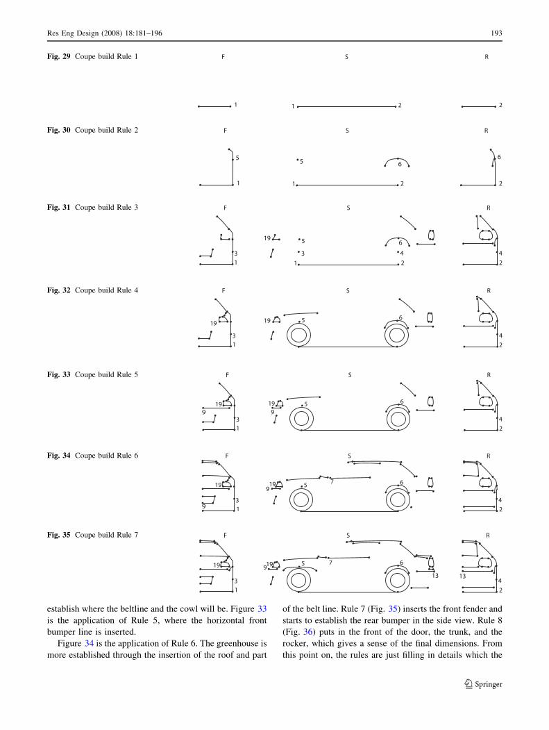
establish where the beltline and the cowl will be. Figure 33
is the application of Rule 5, where the horizontal front
bumper line is inserted.
Figure 34 is the application of Rule 6. The greenhouse is
more established through the insertion of the roof and part
of the belt line. Rule 7 (Fig. 35) inserts the front fender and
starts to establish the rear bumper in the side view. Rule 8
(Fig. 36) puts in the front of the door, the trunk, and the
rocker, which gives a sense of the final dimensions. From
this point on, the rules are just filling in details which the
F RS
1 21 2
Fig. 29 Coupe build Rule 1
F RS
1 21 2
5 65 6
Fig. 30 Coupe build Rule 2
F RS
1 21 2
5 619
3 43 4
Fig. 31 Coupe build Rule 3
F RS
1 2
5 619
3 4
19
Fig. 32 Coupe build Rule 4
F RS
1 2
5 619
3 4
199 9
Fig. 33 Coupe build Rule 5
F RS
1 2
5 619
3 4
199
9
7
Fig. 34 Coupe build Rule 6
F RS
1 2
5 619
3 4
19 97
1313
Fig. 35 Coupe build Rule 7
Res Eng Design (2008) 18:181–196 193
123
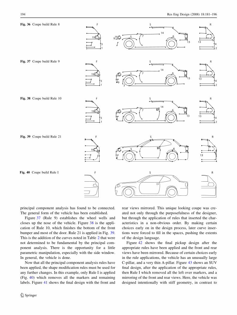
principal component analysis has found to be connected.
The general form of the vehicle has been established.
Figure 37 (Rule 9) establishes the wheel wells and
closes up the nose of the vehicle. Figure 38 is the appli-
cation of Rule 10, which finishes the bottom of the front
bumper and most of the door. Rule 21 is applied in Fig. 39.
This is the addition of the curves noted in Table 2 that were
not determined to be fundamental by the principal com-
ponent analysis. There is the opportunity for a little
parametric manipulation, especially with the side window.
In general, the vehicle is done.
Now that all the principal component analysis rules have
been applied, the shape modification rules must be used for
any further changes. In this example, only Rule I is applied
(Fig. 40) which removes all the markers and remaining
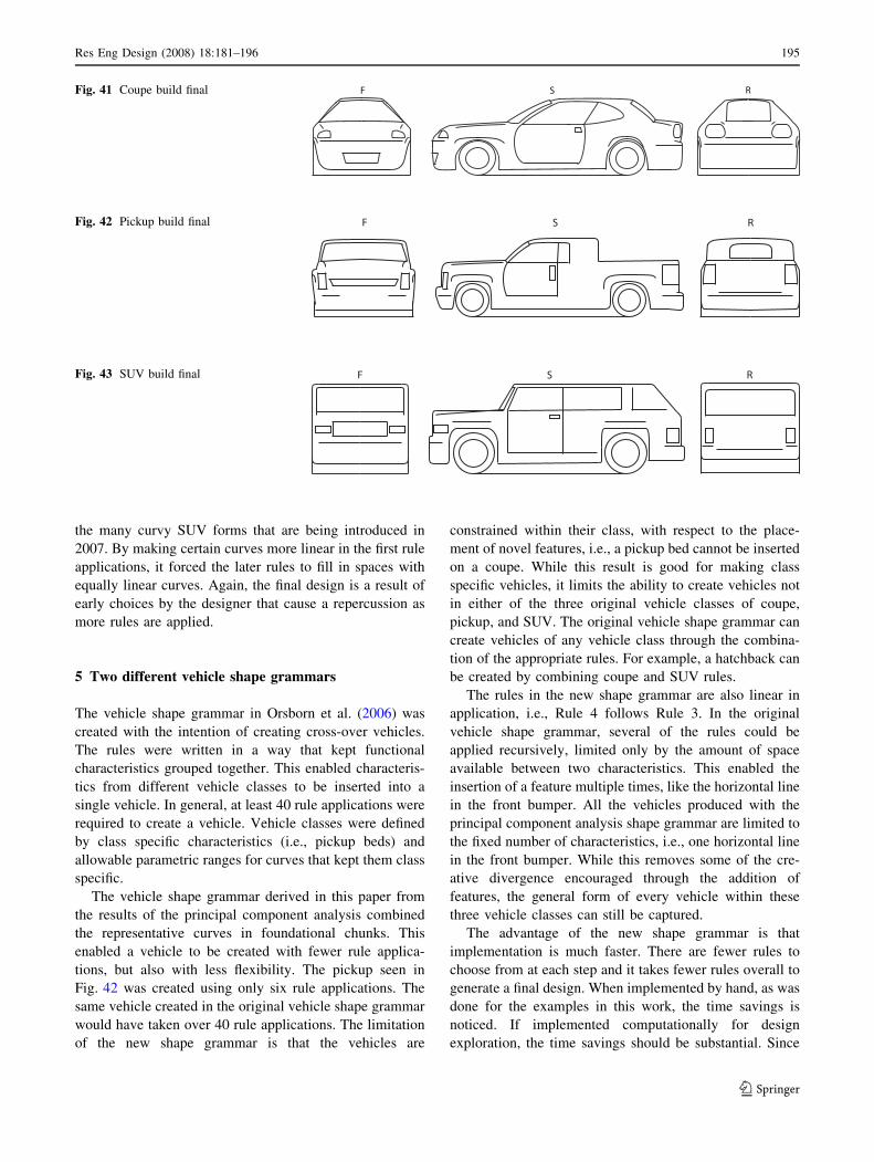
labels. Figure 41 shows the final design with the front and
rear views mirrored. This unique looking coupe was cre-
ated not only through the purposefulness of the designer,
but through the application of rules that inserted the char-
acteristics in a non-obvious order. By making certain
choices early on in the design process, later curve inser-
tions were forced to fill in the spaces, pushing the extents
of the design language.
Figure 42 shows the final pickup design after the
appropriate rules have been applied and the front and rear
views have been mirrored. Because of certain choices early
in the rule applications, the vehicle has an unusually large
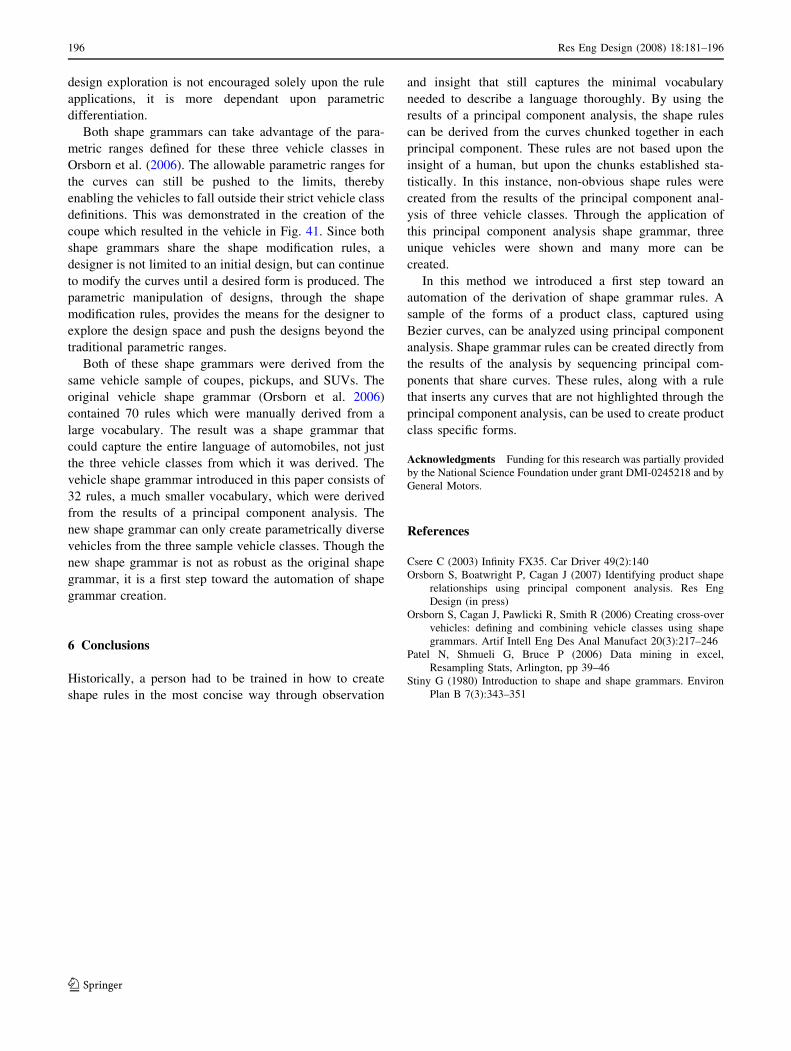
C-pillar, and a very thin A-pillar. Figure 43 shows an SUV
final design, after the application of the appropriate rules,
then Rule I which removed all the left over markers, and a
mirroring of the front and rear views. Here, the vehicle was
designed intentionally with stiff geometry, in contrast to
F RS
1 2
5 619
3 4
19 97
1313
14
Fig. 36 Coupe build Rule 8
F RS
1 2
5 6
3 4
19
9
7
1313
14
3
Fig. 37 Coupe build Rule 9
F RS
1 2
5 6
3 4
19 7
1313
14
Fig. 38 Coupe build Rule 10
F RS
5 619
13
Fig. 39 Coupe build Rule 21
F RSFig. 40 Coupe build Rule I
194 Res Eng Design (2008) 18:181–196
123
the many curvy SUV forms that are being introduced in
2007. By making certain curves more linear in the first rule
applications, it forced the later rules to fill in spaces with
equally linear curves. Again, the final design is a result of
early choices by the designer that cause a repercussion as
more rules are applied.
5 Two different vehicle shape grammars
The vehicle shape grammar in Orsborn et al. (2006) was
created with the intention of creating cross-over vehicles.
The rules were written in a way that kept functional
characteristics grouped together. This enabled characteris-
tics from different vehicle classes to be inserted into a
single vehicle. In general, at least 40 rule applications were
required to create a vehicle. Vehicle classes were defined
by class specific characteristics (i.e., pickup beds) and
allowable parametric ranges for curves that kept them class
specific.
The vehicle shape grammar derived in this paper from
the results of the principal component analysis combined
the representative curves in foundational chunks. This
enabled a vehicle to be created with fewer rule applica-
tions, but also with less flexibility. The pickup seen in
Fig. 42 was created using only six rule applications. The
same vehicle created in the original vehicle shape grammar
would have taken over 40 rule applications. The limitation
of the new shape grammar is that the vehicles are
constrained within their class, with respect to the place-
ment of novel features, i.e., a pickup bed cannot be inserted
on a coupe. While this result is good for making class
specific vehicles, it limits the ability to create vehicles not
in either of the three original vehicle classes of coupe,
pickup, and SUV. The original vehicle shape grammar can
create vehicles of any vehicle class through the combina-
tion of the appropriate rules. For example, a hatchback can
be created by combining coupe and SUV rules.
The rules in the new shape grammar are also linear in
application, i.e., Rule 4 follows Rule 3. In the original
vehicle shape grammar, several of the rules could be
applied recursively, limited only by the amount of space
available between two characteristics. This enabled the
insertion of a feature multiple times, like the horizontal line
in the front bumper. All the vehicles produced with the
principal component analysis shape grammar are limited to
the fixed number of characteristics, i.e., one horizontal line
in the front bumper. While this removes some of the cre-
ative divergence encouraged through the addition of
features, the general form of every vehicle within these
three vehicle classes can still be captured.
The advantage of the new shape grammar is that
implementation is much faster. There are fewer rules to
choose from at each step and it takes fewer rules overall to
generate a final design. When implemented by hand, as was
done for the examples in this work, the time savings is
noticed. If implemented computationally for design
exploration, the time savings should be substantial. Since
S RFFig. 41 Coupe build final
F RSFig. 42 Pickup build final
F RSFig. 43 SUV build final
Res Eng Design (2008) 18:181–196 195
123
design exploration is not encouraged solely upon the rule
applications, it is more dependant upon parametric
differentiation.
Both shape grammars can take advantage of the para-
metric ranges defined for these three vehicle classes in
Orsborn et al. (2006). The allowable parametric ranges for
the curves can still be pushed to the limits, thereby
enabling the vehicles to fall outside their strict vehicle class
definitions. This was demonstrated in the creation of the
coupe which resulted in the vehicle in Fig. 41. Since both
shape grammars share the shape modification rules, a
designer is not limited to an initial design, but can continue
to modify the curves until a desired form is produced. The
parametric manipulation of designs, through the shape
modification rules, provides the means for the designer to
explore the design space and push the designs beyond the
traditional parametric ranges.
Both of these shape grammars were derived from the
same vehicle sample of coupes, pickups, and SUVs. The
original vehicle shape grammar (Orsborn et al. 2006)
contained 70 rules which were manually derived from a
large vocabulary. The result was a shape grammar that
could capture the entire language of automobiles, not just
the three vehicle classes from which it was derived. The
vehicle shape grammar introduced in this paper consists of
32 rules, a much smaller vocabulary, which were derived
from the results of a principal component analysis. The
new shape grammar can only create parametrically diverse
vehicles from the three sample vehicle classes. Though the
new shape grammar is not as robust as the original shape
grammar, it is a first step toward the automation of shape
grammar creation.
6 Conclusions
Historically, a person had to be trained in how to create
shape rules in the most concise way through observation
and insight that still captures the minimal vocabulary
needed to describe a language thoroughly. By using the
results of a principal component analysis, the shape rules
can be derived from the curves chunked together in each
principal component. These rules are not based upon the
insight of a human, but upon the chunks established sta-
tistically. In this instance, non-obvious shape rules were
created from the results of the principal component anal-
ysis of three vehicle classes. Through the application of
this principal component analysis shape grammar, three
unique vehicles were shown and many more can be
created.
In this method we introduced a first step toward an
automation of the derivation of shape grammar rules. A
sample of the forms of a product class, captured using
Bezier curves, can be analyzed using principal component
analysis. Shape grammar rules can be created directly from
the results of the analysis by sequencing principal com-
ponents that share curves. These rules, along with a rule
that inserts any curves that are not highlighted through the
principal component analysis, can be used to create product
class specific forms.
Acknowledgments Funding for this research was partially provided
by the National Science Foundation under grant DMI-0245218 and by
General Motors.
References
Csere C (2003) Infinity FX35. Car Driver 49(2):140
Orsborn S, Boatwright P, Cagan J (2007) Identifying product shape
relationships using principal component analysis. Res Eng
Design (in press)
Orsborn S, Cagan J, Pawlicki R, Smith R (2006) Creating cross-over
vehicles: defining and combining vehicle classes using shape
grammars. Artif Intell Eng Des Anal Manufact 20(3):217–246
Patel N, Shmueli G, Bruce P (2006) Data mining in excel,
Resampling Stats, Arlington, pp 39–46
Stiny G (1980) Introduction to shape and shape grammars. Environ
Plan B 7(3):343–351
196 Res Eng Design (2008) 18:181–196
123