Embed Size (px)
Citation preview
Article
A Memristor-based Cascaded Neural Networks forSpecific Target Recognition
Sheng-Yang Sun, Hui Xu, Jiwei Li, Yi Sun, Qingjiang Li, Zhiwei Li * and Haijun Liu *
1
2
3
4
5
6
7
8
9
10
11
12
13
14
College of Electronic Science, National University of Defense Technology, Changsha 410073, China; [email protected] (S.-Y. S.); [email protected] (H. X.); [email protected],cn (J. L.);[email protected] (Y. S.); [email protected] (Q. L.)* Correspondence: [email protected] (Z. L.); [email protected] (H. L.)
Abstract: Multiply-accumulate calculations using a memristor crossbar array is an important method to realize neuromorphic computing. However, the memristor array fabrication technology is still immature, and it is difficult t o f abricate l arge-scale a rrays w ith h igh-yield, w hich restricts the development of memristor-based neuromorphic computing technology. Therefore, cascading small-scale arrays to achieve the neuromorphic computational ability that can be achieved by large-scale arrays, which is of great significance for promoting the application of memristor-based neuromorphic computing. To address this issue, we present a memristor-based cascaded framework with some basic computation units, several neural network processing units can be cascaded by this means to improve the processing capability of the dataset. Besides, we introduce a split method to reduce pressure of input terminal. Compared with VGGNet and GoogLeNet, the proposed cascaded framework can achieve 93.54% Fashion-MNIST accuracy under the 4.15M parameters. Extensive experiments with Ti/AlOx/TaOx/Pt we fabricated are conducted to show that the circuit simulation results can still provide a high recognition accuracy, and the recognition accuracy loss after circuit simulation can be controlled at around 0.26%.
Keywords: cascaded neural networks; memristor crossbar; convolutional neural networks15
1. Introduction16
Convolutional neural networks (CNNs) have been widely used in computer vision tasks such17
as image classification [1][2][3], they are widely popular in industry for their superior accuracy on18
datasets. Some concepts about CNNs were proposed by Fukushima in 1980 [4]. In 1998, LeCun et19
al. proposed the LeNet-5 CNNs structure based on a gradient-based learning algorithm [5]. With20
the development of deep learning algorithms, the dimension and complexity of CNNs layers have21
grown significantly. However, state-of-the-art CNNs require too many parameters and compute at22
billions of FLOPs, which prevents them from being utilized in embedded applications. For instance,23
the AlexNet [1] proposed by Krizhevsky et al. in 2012, requires 60M parameters and 650K neurons;24
ResNet [6], which is broadly used in detection task [7], has a complexity of 7.8 GFLOPs and fails to25
achieve real-time applications even with a powerful GPU.26
For the past few years, embedded neuromorphic processing systems have acquired significant27
advantages, such as the ability to solve the image classification problems while consuming very28
little area and power consumption [8]. In addition to these advantages, neuromorphic computing29
can also be used to simulate the functions of human brains [9]. With the rapid development of the30
VLSI industry, increasingly more devices are beginning to be miniaturized and integrated [10]. As31
mentioned above, CNNs lead to an exploding number of network synapses and neurons in which the32
relevant hardware costs will be huge [11], these complex computations and high memory requirements33
make it impractical for the application of embedded systems, robotics and real-time or mobile scenarios34
in general.35
In recent years, the memristor [12] has received significant attention as synapses for neuromorphic36
systems. The memristor is a non-volatile device that can store the synaptic weights of neural networks.37
Preprints (www.preprints.org) | NOT PEER-REVIEWED | Posted: 31 January 2019
© 2019 by the author(s). Distributed under a Creative Commons CC BY license.
Preprints (www.preprints.org) | NOT PEER-REVIEWED | Posted: 31 January 2019 doi:10.20944/preprints201901.0319.v1
© 2019 by the author(s). Distributed under a Creative Commons CC BY license.
2 of 11
Voltage pulses can be applied to memristors to change their conductivity and tune them to a specific38
resistance [13]. A memristor crossbar array can naturally carry out vector-matrix multiplication which39
is a computationally expensive operation for neural networks. It has been recently demonstrated that40
analog vector-matrix multiplication can be of orders of magnitude that are more efficient than ASIC,41
GPUs or FPGA based implementations [14].42
Some neural network architectures based on the memristor crossbar have been proposed [15–17],43
these network architectures utilize memristor crossbar to perform convolution computation iterations44
which also cost too much time and require high memory. On the other hand, the fabrication technology45
of large-scale memristor crossbar array is still immature [18,19], however useful cascaded framework46
in real applications with memristor-based architectures have seldom been reported. To make full47
use of limited memristor resources and make the system work at high speed in real-time processing48
applications, we present a memristor-based cascaded framework with some neuromorphic processing49
chip. That means several neural network processing chips can be cascaded to improve the processing50
capability of the dataset. The basic computation unit in this work builds on our prior work devoloping51
memristor-based CNNs architecture [20], which has validated that the three-layer CNNs with Abs52
activation function can get desired recognition accuracy.53
The rest of this paper is organized as follows, Section II presents the cascaded method based on54
the basic computation unit and a split method, including the circuits implemented based on memristor55
crossbar array. Section III exhibits the experimental results. The final Section IV concludes the paper.56
2. Proposed Cascaded Method57
To have a better understanding of cascaded method, we first introduce basic units that make up58
the cascaded network, and then a detailed description of our cascaded CNN framework is presented.59
2.1. Basic Computation Unit60
To take full advantage of limited memristor array, a three-layer simplified CNNs is used as the61
basic computation unit (BCU). The structure of this network is shown in Figure 1.62
Convolution Layer Pooling Layer Fully Connected LayerInput ImageClassification
…
Max Selected
Spike Flow
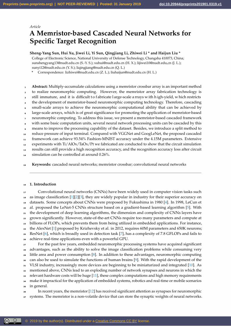
Figure 1. The basic computation unit architecture. It consists of three layers, behind the input layeris convolution layer which consists of k kernels, followed by a average-pooling layer and a fullyconnected layer.
The simplified CNNs includes three layers. The convolution layer includes k kernels with kernel63
size Ks × Ks followed by absolute nonlinearity function (Abs), which extracts the features from the64
input images and produce the feature maps. The average-pooling obtains spatial invariance while65
scaling feature maps with pooling size Ps × Ps from their preceding layers. A sub-sample is taken from66
each feature map, and it reduces the data redundancy. The fully connected layer (FCL) performs the67
final classification or image reconstruction, it takes the extracted feature maps and multiplies a weight68
matrix following a dense matrix vector multiplication pattern.69
G = H(I∗) = σ(W · G∗ + b)
= σ(W · (G∗∗ ∗W∗) + b)
= σ(W · (δ(W∗∗ ∗ I∗ + b∗) ∗W∗) + b)
(1)
Preprints (www.preprints.org) | NOT PEER-REVIEWED | Posted: 31 January 2019 Preprints (www.preprints.org) | NOT PEER-REVIEWED | Posted: 31 January 2019 doi:10.20944/preprints201901.0319.v1
3 of 11
input image (!∗)
BCU #2_1BCU #1_2
BCU #1_3
BCU #1_1
BCU #3_1
output
#
BCU #1_1
BCU #1_2
BCU #1_M
BCU #2_1
BCU #2_N
BCU #3_1 BCU #3_P
…
…
…input image
Part #1 Part #2 Part #3
M-BCUs
N-BCUsP-BCUs
F1 F2
(a)
(b)
fimage1_3 (I *)
fimage1_ 2 (I *)
fimage1_1 (I *)
fimage2_1 (F ) fimage
3_1 ( fimage2_1 )
W1 × H1
W1 × H1
output
W × H
W × H
W × H
W × H
W × H
W1 × H1
W1 × H1
W1 × H1
W1 × H1
W2 × H2
W2 × H2
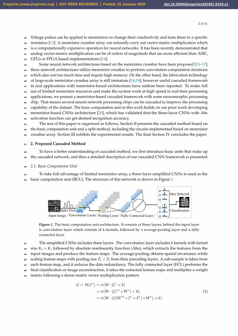
Figure 2. The diagram of the proposed cascaded framework. (a): Standard cascaded networkframework "M-N-P". (b): The typical "3-1-1" cascaded type.
where H : RC×W×H → RC∗×W∗×H∗ is the transformation in the BCU (in other words, BCU70
performs the image transformation), C is the number of channels of input image, σ indicates the71
hyperbolic tangent function, δ indicates the Abs function, ∗ represents the convolution operator, b, b∗72
are bias value, and W, W∗, W∗∗ represent the weight matrix of each layer, respectively (refer to Figure73
1).74
2.2. The Proposed Cascaded Framework75
Aim to combine several monolithic networks (BCUs) to obtain better performance, we propose a76
cascaded CNN network, whose specific design can be seen in Figure 2a.77
The cascaded framework includes three parts. Given the output G ∈ RC×W×H generated from a78
part, a reconstruction transformation f : RC×W×H → RC×W×H is applied to aggregate outputs over79
all BCUs of this part, where C is the number of channels of input image, W and H are the spatial80
dimensions. The output of kth part is described as81
Fk = Gk_1 ⊕ Gk_2 ⊕ ...⊕ Gk_n (2)
Fk+1 = Gk+1_1 ⊕ Gk+1_2 ⊕ ...⊕ Gk+1_m
= Hk+1_1(Fk)⊕ ...⊕ Hk+1_m(Fk)(3)
where Gk_n is the output of the nth BCU of the kth part, and ⊕ represents the reconstruction operator82
which combined with several original outputs using an element-wise addition to produce a new83
output. The new output Fk is treated as input to feed into the k + 1 part. Equation (3) describes the84
calculation process of the next part output from the kth part, here the H(·) is the transformation of85
BCU.86
As shown in Figure 2a, the Part #1 includes M BCUs, which extract features from the input image87
for the subsequent subnetworks. The output F1 ∈ RC1×W1×H1 is generated by reconstruction operation88
Preprints (www.preprints.org) | NOT PEER-REVIEWED | Posted: 31 January 2019 Preprints (www.preprints.org) | NOT PEER-REVIEWED | Posted: 31 January 2019 doi:10.20944/preprints201901.0319.v1
4 of 11
from the BCU outputs G1_n ∈ RC1×W1×H1 (n ∈ [1, M]). The next Part #2 includes N BCUs, which89
take the outputs of the previous part as the inputs to produce the F2 ∈ RC2×W2×H2 . The final Part90
#3 includes P BCUs, the first BCU takes the F2 as the input to generate the G3_1 ∈ RC3×W3×H3 , and91
the second BCU uses G3_1 to produce the G3_2, and so on until G3_P ∈ RC3×W3×H3 is produced. This92
cascaded mode is called the “M-N-P" type.93
The typical "3-1-1" cascaded framework is shown in Figure 2b, it includes five BCUs which three94
BCUs in parallel and two in series to produce the classification output.95
2.3. Memristor-based Implementation96
Based on BCU architecture, the computation unit can be treated as an image transformator.97
According to Equation (1), the output G can be described as a multiply-addition calculation so that it98
can be performed by several memristor.99
As mentioned above, the BCU is a simplied CNN architecture. After the network training is100
finished, the weight matrix also has some negative weights. Therefore, the converted mapping method101
is needed to be applied. We assume that W represents a 2×2 weights matrix, and it includes positive102
and negative values. Then, the W is converted to the 2×4 matrix so that the memristor crossbar can103
easily calculate the weighted-sum with the amplifiers. Each original value is extended in two parts,104
W+ and W−. If one element is a positive value, then the value is defined in W+, and the value of W−105
is zero. In contrast, the negative element value is defined in W− and the W+ is zero. Similarly, if the106
arrangement of the memristor in the array corresponds to the converted matrix, the Ro f f takes the107
place of the zero element.108
The BCU can produce entire output feature maps in one processing cycle. It no longer needs109
to wait for an output feature map to be completed before the next operation can be executed. This110
outcome means that it eliminates the requirement of a data storage device between each network layer.111
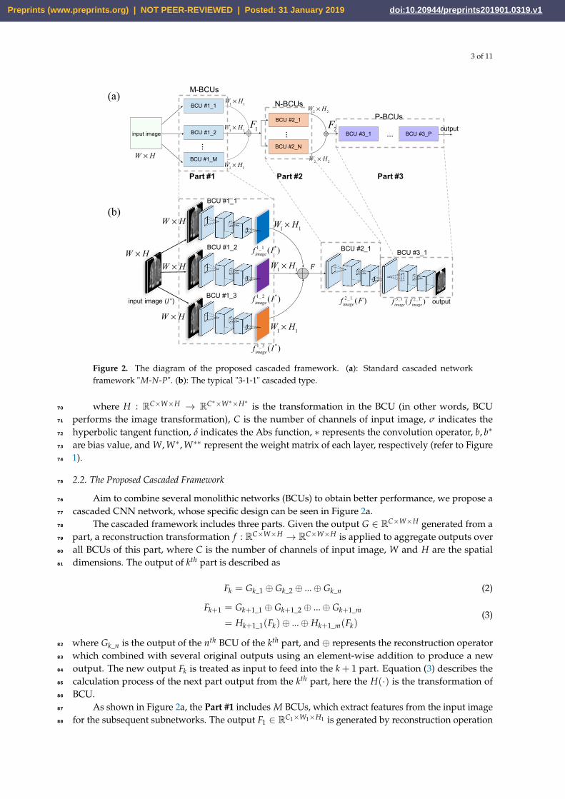
Figure 3a is a simple demo about performing a convolution computation in a memristor crossbar. A112
two-dimensional input image is converted into a one-dimensional electrical signal as an input, and the113
weighted-sum computation is completed by the memristor crossbar array.114
-4 -3 -2 -1 0 1 2 3 4 Input Voltage (V)
-1
-0.5
0
0.5
1
Act
ivat
ion
Volta
ge (V
)
Tanh Function op-amp Approx.0.5
0.2
0.3 1
1
0.7
1
0 0
0.4
0.6
0 0.1
0 0 00.3
!"!#!$!%
!"!#!$
!%input field
convolution kernel synapses
-0.2
-0.6 0.5
0.4 0.2
0.7 0.8
0.9 -0.3 0.2 -0.1
0.5 -0.1 0.3 0.4
⊗⊗⊗⊗
Wi,1
Wi,2
Wi,3
Wi,4
1Wi,1
1Wi,2
1Wi,3
1Wi,4
Roff
Roff
Roff
Roff
W + W −(a) (b)
Figure 3. (a): Diagram displaying a memristor crossbar that is capable of completing a convolutioncomputation. (b): Comparison of the tanh activation function and the amplifier alternative.
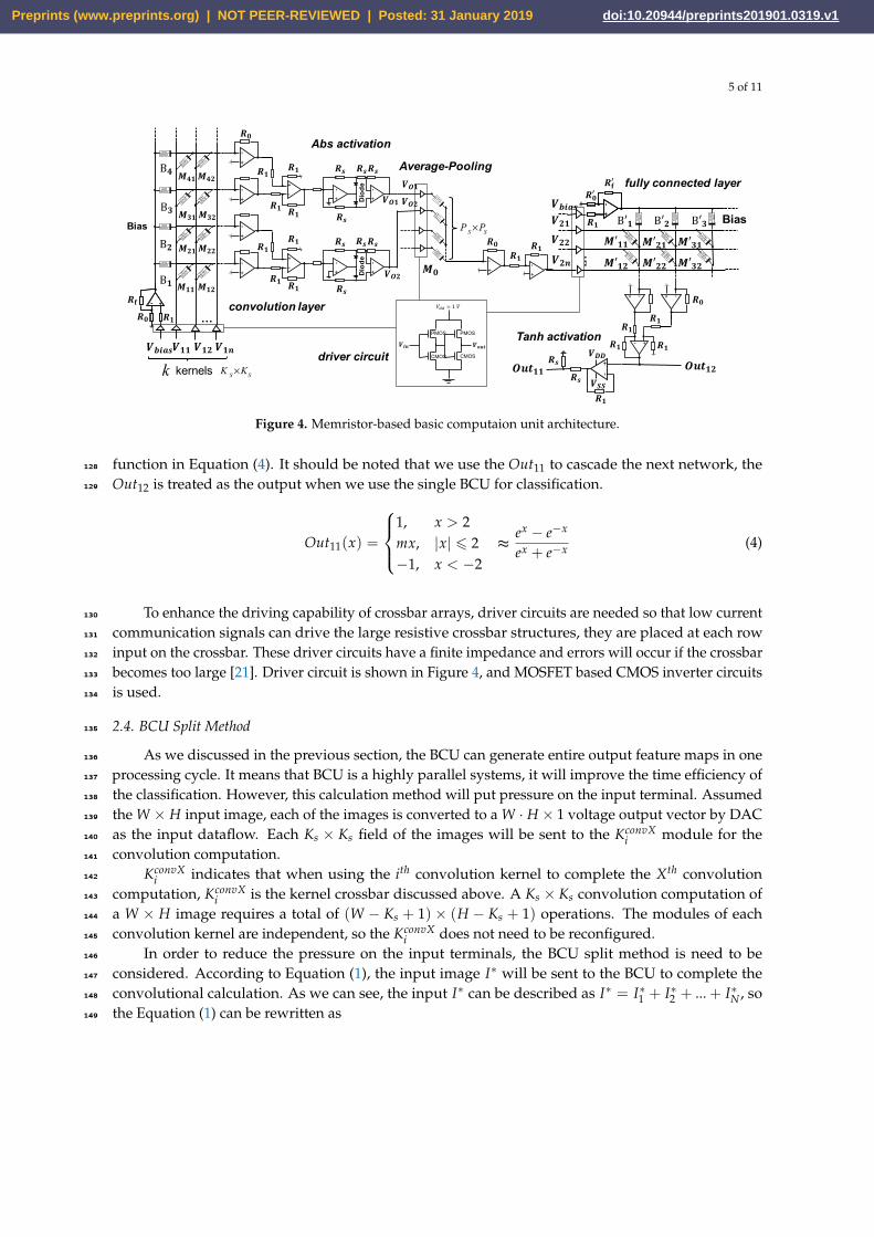
A memristor-based computation unit architecture is shown in Figure 4. A K2s × P matrix M(1)(Mij)115
corresponds to all outputs of convolutional kernels (here P = k× 2, two memristors represent one116
synapse), so the convolution layer consists of some kernels crossbar. The Abs activation module follows117
the kernels crossbar, it consists of two op-amps and two diodes. The activation module generates118
signals (like VO1 or VO2 in Figure 4) and sends these signals to the Average-Pooling modules. The119
pooling module consists some P2s × 1 crossbar and the matrix weight is 1/P2
s , the multiply-addition120
calculation is applied to complete the pooling operations. The fully connected layer receives the signals121
from pooling module, a L× N matrix M(2)(M′ij) corresponds to N neurons and L inputs. The Tanh122
activation circuit at the end of fully connected layer in Figure 4 is used to both scale the output voltage123
and implement the Tanh activation function. There is an alternative calculation to complete the Tanh124
activation function by referring the Equation (4). A linear amplifier activation function (with bounded125
upper and lower voltage rails) matches the Tanh relatively closely, and the simulation results show126
that this is an effective alternative (in Figure 3b). To obtain the optimal linear, m = 1/2 fits the Tanh127
Preprints (www.preprints.org) | NOT PEER-REVIEWED | Posted: 31 January 2019 Preprints (www.preprints.org) | NOT PEER-REVIEWED | Posted: 31 January 2019 doi:10.20944/preprints201901.0319.v1
5 of 11
Average-Pooling
𝑴𝟐𝟏
𝑴𝟑𝟏
𝑴𝟒𝟏
𝑴𝟐𝟐
𝑴𝟑𝟐
𝑴𝟒𝟐
𝑴𝟏𝟏 𝑴𝟏𝟐
𝑽𝒃𝒊𝒂𝒔𝑽𝟏𝟏 𝑽𝟏𝟐 𝑽𝟏𝒏
B𝟏
B𝟐
B𝟑
B𝟒 𝑹𝒔
𝑹𝒔
𝑹𝒔𝑹𝒔
𝑹𝒔
𝑹𝒔
𝑹𝒔𝑹𝒔
𝑽𝑶𝟏𝑽𝑶𝟐
PS×PS
𝑴𝟎
Bias
convolution layer
𝑽𝑶𝟐
𝑽𝑶𝟏
PMOS PMOS
CMOS CMOS
!"# !$%&
'(( = 1'
driver circuit
Abs activation
kernels K S×KSk
𝑹𝟏
𝑹𝟏
𝑹𝟎
…
-
+
-+
-
+
-
+Diode
- +- +
-
+
-
+
-
+
-
+
-
+Diode
-
+
𝑹𝟏
𝑹𝟏 𝑹𝟏
𝑹𝟏
𝑹𝟏
𝑹𝟏
𝑹𝐟𝑹𝟏𝑹𝟎
-
+
-
+
𝑹𝟎𝑹𝟏
𝑹𝟏
!"#
$%%
-
+
$&&!'!'
(′** (′+* (′,*(′*+ (′++ (′,+
$-./'$+*$++
B′* B′+ B′, Bias
…$+1
-
+
-
+
!2
!*
-+
- +
-+
!*!*
!*
!*
!2#
𝑹𝟏
fully connected layer
Tanh activation
𝑶𝒖𝒕𝟏𝟏 𝑶𝒖𝒕𝟏𝟐
Figure 4. Memristor-based basic computaion unit architecture.
function in Equation (4). It should be noted that we use the Out11 to cascade the next network, the128
Out12 is treated as the output when we use the single BCU for classification.129
Out11(x) =
1, x > 2mx, |x| 6 2 ≈−1, x < −2
ex − e−x
ex + e−x (4)
To enhance the driving capability of crossbar arrays, driver circuits are needed so that low current130
communication signals can drive the large resistive crossbar structures, they are placed at each row131
input on the crossbar. These driver circuits have a finite impedance and errors will occur if the crossbar132
becomes too large [21]. Driver circuit is shown in Figure 4, and MOSFET based CMOS inverter circuits133
is used.134
2.4. BCU Split Method135
As we discussed in the previous section, the BCU can generate entire output feature maps in one136
processing cycle. It means that BCU is a highly parallel systems, it will improve the time efficiency of137
the classification. However, this calculation method will put pressure on the input terminal. Assumed138
the W × H input image, each of the images is converted to a W · H × 1 voltage output vector by DAC139
as the input dataflow. Each Ks × Ks field of the images will be sent to the KconvXi module for the140
convolution computation.141
KconvXi indicates that when using the ith convolution kernel to complete the Xth convolution142
computation, KconvXi is the kernel crossbar discussed above. A Ks × Ks convolution computation of143
a W × H image requires a total of (W − Ks + 1) × (H − Ks + 1) operations. The modules of each144
convolution kernel are independent, so the KconvXi does not need to be reconfigured.145
In order to reduce the pressure on the input terminals, the BCU split method is need to be146
considered. According to Equation (1), the input image I∗ will be sent to the BCU to complete the147
convolutional calculation. As we can see, the input I∗ can be described as I∗ = I∗1 + I∗2 + ... + I∗N , so148
the Equation (1) can be rewritten as149
Preprints (www.preprints.org) | NOT PEER-REVIEWED | Posted: 31 January 2019 Preprints (www.preprints.org) | NOT PEER-REVIEWED | Posted: 31 January 2019 doi:10.20944/preprints201901.0319.v1
6 of 11
G = σ(W · (δ(W∗∗ ∗ I∗ + b∗) ∗W∗) + b)
= σ(W · (δ(W∗∗ ∗ (I∗1 + ... + I∗N) + b∗) ∗W∗) + b)
= σ(W · (δ(W∗∗ ∗ I∗1 + b∗) ∗W∗) + b)
+ σ(W · (δ(W∗∗ ∗ I∗2 + b∗) ∗W∗) + b) + ...
+ σ(W · (δ(W∗∗ ∗ I∗N + b∗) ∗W∗) + b)
= H(I∗1 )⊕ H(I∗2 )⊕ ...⊕ H(I∗N)
(5)
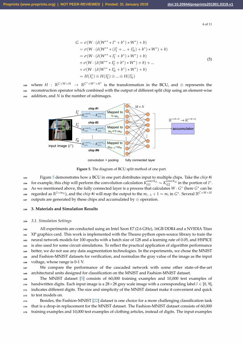
where H : RC×W×H → RC∗×W∗×H∗ is the transformation in the BCU, and ⊕ represents the150
reconstruction operator which combined with the output of different split chip using an element-wise151
addition, and N is the number of subimages.152
chip #1
chip #2
chip #N… … …
Kk11convX11 ~ Kk12
convX12
Kk 21convX21 ~ Kk 22
convX22
KkN1convXN 1 ~ KkN 2
convXN 2
accumulator
fully connected layerconvolution + pooling
M × NMapped to
1~𝑚"
Mapped to 𝑚"+1~𝑚#
Mapped to 𝑚$%"~𝑚$
input image (𝐼∗)
𝐼"∗
𝐼#∗
𝐼$∗
!C×W×H → !C×W×H
Figure 5. The diagram of BCU split method of one part.
Figure 5 demonstrates how a BCU in one part distributes input to multiple chips. Take the chip #i153
for example, this chip will perform the convolution calculation KconvXi1i11 ∼ KconvXi2
i12 in the portion of I∗.154
As we mentioned above, the fully connected layer is a process that calculates W · G∗ (here G∗ can be155
regarded as R1×mN ), and the chip #i will map the output to the mi−1 + 1 ∼ mi in G∗. Several RC×W×H156
outputs are generated by these chips and accumulated by ⊕ operation.157
3. Materials and Simulation Results158
3.1. Simulation Settings159
All experiments are conducted using an Intel Xeon E7 (2.6 GHz), 16GB DDR4 and a NVIDIA Titan160
XP graphics card. This work is implemented with the Theano python open-source library to train the161
neural network models for 100 epochs with a batch size of 128 and a learning rate of 0.05, and HSPICE162
is also used for some circuit simulations. To reflect the practical application of algorithm performance163
better, we do not use any data augmentation technologies. In the experiments, we chose the MNIST164
and Fashion-MNIST datasets for verification, and normalize the gray value of the image as the input165
voltage, whose range is 0-1 V.166
We compare the performance of the cascaded network with some other state-of-the-art167
architectural units designed for classification on the MNIST and Fashion-MNIST dataset.168
The MNIST dataset [5] consists of 60,000 training examples and 10,000 test examples of169
handwritten digits. Each input image is a 28×28 grey scale image with a corresponding label l ∈ [0, 9],170
indicates different digits. The size and simplicity of the MNIST dataset make it convenient and quick171
to test models on.172
Besides, the Fashion-MNIST [22] dataset is one choice for a more challenging classification task173
that is a drop-in replacement for the MNIST dataset. The Fashion-MNIST dataset consists of 60,000174
training examples and 10,000 test examples of clothing articles, instead of digits. The input examples175
Preprints (www.preprints.org) | NOT PEER-REVIEWED | Posted: 31 January 2019 Preprints (www.preprints.org) | NOT PEER-REVIEWED | Posted: 31 January 2019 doi:10.20944/preprints201901.0319.v1
7 of 11
have the same format as the MNIST dataset and are 28×28 grey scale images with corresponding176
labels l ∈ [0, 9]. The Fashion-MNIST dataset is a step up from the MNIST dataset. It remains simple177
enough that complex architectures, learning algorithms, and models are not needed to view progress178
and soundly measure performance.179
The weights of neural network are converted to conductivity values of memristor device by180
Equation (6). The Cmax and Cmin indicate the maximum and minimum conductances, respectively. The181
W is the original weights set, and the Wmax represents the maximum absolute value of the weights set,182
and the Ci is the conductance of the memristor crossbar array.183
Ci =Cmax − Cmin
Wmax· |Wi|+ Cmin (6)
The 1T1R memristor crossbar array which stores the network weights is used for simulation. The184
weights obtained from training with the theano are programmed into a crossbar where each wire185
segment has a resistance of 2Ω, and 5% programmed erros were generated in memristor programming186
simulation process. The circuit structure in HSPICE is shown in Figure 4. The process of simulation187
implemented is illustrated as below.188
1. Convert test image samples to voltage (0-1 V).189
2. Execute software simulation (used Python) and circuit simulation (used HSPICE) based on step 1.190
3. Obtain difference of the potential output (Difference = HSPICE potential - Python output) from191
Python and HSPICE.192
4. Get the labels of test samples from dataset, and determine whether the results of circuit simulation193
are correct (the label that corresponds the maximum voltage is the output).194
The Python (uses theano library) is applied to complete the software simulation, the model195
weights are converted to memristance, and the Python output is compared with the output of the196
HSPICE simulation. We select the number which has the maximum output voltage in the fully197
connected layer as the HSPICE output, the number is compared with the label of the dataset.198
3.2. Memristor Materials199
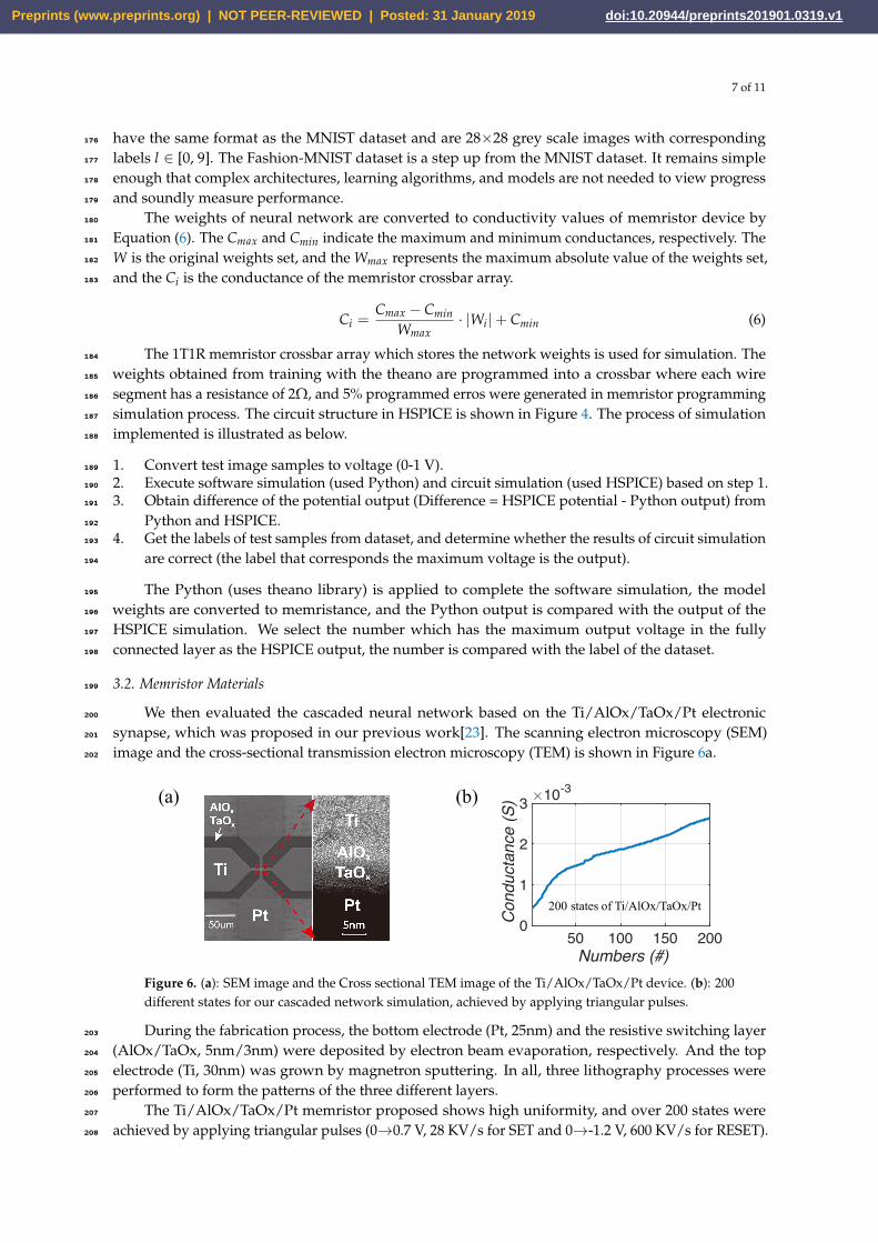
We then evaluated the cascaded neural network based on the Ti/AlOx/TaOx/Pt electronic200
synapse, which was proposed in our previous work[23]. The scanning electron microscopy (SEM)201
image and the cross-sectional transmission electron microscopy (TEM) is shown in Figure 6a.202
(a) (b)
50 100 150 200 Numbers (#)
0
1
2
3
Con
duct
ance
(S) 10-3
200 states of Ti/AlOx/TaOx/Pt
Figure 6. (a): SEM image and the Cross sectional TEM image of the Ti/AlOx/TaOx/Pt device. (b): 200different states for our cascaded network simulation, achieved by applying triangular pulses.
During the fabrication process, the bottom electrode (Pt, 25nm) and the resistive switching layer203
(AlOx/TaOx, 5nm/3nm) were deposited by electron beam evaporation, respectively. And the top204
electrode (Ti, 30nm) was grown by magnetron sputtering. In all, three lithography processes were205
performed to form the patterns of the three different layers.206
The Ti/AlOx/TaOx/Pt memristor proposed shows high uniformity, and over 200 states were207
achieved by applying triangular pulses (0→0.7 V, 28 KV/s for SET and 0→-1.2 V, 600 KV/s for RESET).208
Preprints (www.preprints.org) | NOT PEER-REVIEWED | Posted: 31 January 2019 Preprints (www.preprints.org) | NOT PEER-REVIEWED | Posted: 31 January 2019 doi:10.20944/preprints201901.0319.v1
8 of 11
The device which has the multilevel characteristic can be repeatedly programmed to different target209
resistance states from 1KΩ to 12KΩ, indicating the great potential for neuromorphic computing210
applications.211
Figure 6b demonstrates that 200 states achieved by applying triangular pulses are utilized for212
circuits simulations, the trained matrix weights are converted to conductivity values that fall within213
the bounded range of states. Equation (6) introduces the method of weight mapping. In the actual214
simulation, the closest value is selected from the 200 states.215
3.3. Simulation Results216
In this section, we compare the cascaded model with other state-of-the-art architectures to verify217
the classification performance. Circuit simulation experiments are used to verify the correctness of the218
circuit design and the impact of the device on the recognition accuracy.219
3.3.1. Comparison With Other State-of-the-art Architectures220
Table 1. Cascaded architecture for Fashion-MNIST under the 4.15 M parameters. The number beforethe "Cascaded" is the number of the BCUs. "×14" indicates the cascaded network uses 14 convolutionkernels.
Stage Output Size 7-Cas.×14 (4-2-1) 8-Cas.×14 (4-2-2) 9-Cas.×14 (4-3-2)
28 × 28 image
Part #1 20 × 203×3, 5×5, 7×7, 9×9 conv.
2×2 average-pool
Part #2 20 × 209×9, 9×9 conv, Abs2×2 average-pool
9×9, 9×9 conv.2×2 average-pool
3×3, 5×5, 7×7 conv.2×2 average-pool
Part #3 6 × 69×9 conv.
2×2 average-pool9×9, 9×9 conv.
2×2 average-pool9×9, 9×9 conv.
2×2 average-poolClassifier 1 × 1 Fully Connected Layer + softmax
Parameters 3.45 M 3.46 M 4.15 MAccuracy (%) 93.12 93.25 93.54
Based on basic computation unit, we test the cascaded network with different architecture on221
MNIST and Fashion-MNIST datasets, the configuration details and performance is shown in Table 1.222
The BCU which has 14 kernels with 9×9 kernel size and 2×2 pooling size, and Abs activation function223
applied can achieve 89.68% Fashion-MNIST accuracy, while Cascaded×14 achieves improvements of224
3.18%, 3.44%, 3.57% and 3.86% under 4.15M parameters. The output sizes of the Part#1 and Part#2 are225
both 20×20. 7-Cascaded×14(4-1-1) provides 93.12% Fashion-MNIST accuracy which uses 9×9 kernel.226
8-Cascaded×14(4-2-2) slightly outperforms “4-2-1" (∼0.13%) with 10,000 more parameters. It can be227
seen that cascaded models can achieve 93.54% accuracy under the 4.15M parameters.228
Table 2. Accuracy rates (%) on the MNIST and Fashion-MNIST datasets.
Models Parameters MNIST Acc. Fashion-MNIST Acc.
VGGNet-16 [2] 26 M 99.22 93.35GoogLeNet [3] 6.8 M 99.45 93.52ResNet-50 [6] 25.5 M 99.55 94.24
CapsuleNet [24] 11.3 M 99.35 93.55This work 4.15 M (<500K per single BCU) 99.55 93.54
We further compare the cascaded architecture with the building structures of four state-of-the-art229
models, VGGNet[2], GoogLeNet[3], ResNet[6] and CapsuleNet[24]. The BCU architecture in Table230
2 includes 14 kernels, 2×2 average-pool with Abs activation function. A “4-3-2" cascaded type is231
implemented, “3×3, 5×5, 7×7, 9×9 conv." is in Part #1, “3×3, 5×5, 7×7 conv." is in Part #2, and “9×9,232
9×9 conv." in Part #3. VGGNet-16 provides 99.22% MNIST accuracy and 93.35% Fashion-MNIST233
Preprints (www.preprints.org) | NOT PEER-REVIEWED | Posted: 31 January 2019 Preprints (www.preprints.org) | NOT PEER-REVIEWED | Posted: 31 January 2019 doi:10.20944/preprints201901.0319.v1
9 of 11
accuracy, GoogLeNet achieves 99.45% MNIST accuracy and 93.52% Fashion-MNIST accuracy with234
6.8M parameters, CapsuleNet provides 99.35% and 93.55% accuracy on MNIST and Fashion-MNIST235
datasets respectively, while ResNet-50 produces remarkably better Fashion-MNIST accuracy of 94.24%.236
However, they are all computationally intensive (approximately 26M parameters of VGGNet). In237
comparison, 9-Cascaded×14(4-3-2) achieves 99.55% MNIST accuracy and 93.54% Fashion-MNIST238
accuracy under 4.15M parameters. From the table it can be seen that the cascaded network significantly239
surpasses VGGNet-16 by 0.33% on MNIST accuracy with 6.26× fewer parameters, and slightly240
outperforms GoogLeNet 0.02% Fashion-MNIST accuracy with 1.64× fewer parameters.241
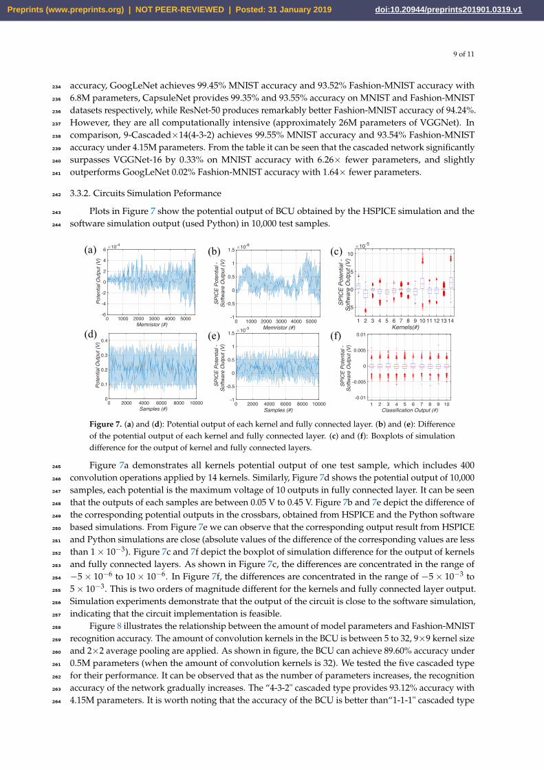
3.3.2. Circuits Simulation Peformance242
Plots in Figure 7 show the potential output of BCU obtained by the HSPICE simulation and the243
software simulation output (used Python) in 10,000 test samples.244
(b)(a) (c)
1 2 3 4 5 6 7 8 9 10 11 12 13 14 Kernels(#)
-5
0
5
10
SPI
CE
Pote
ntia
l -
Softw
are
Out
put (
V)
10-5
1 2 3 4 5 6 7 8 9 10 Classification Output (#)
-0.01
-0.005
0
0.005
0.01 S
PIC
E Po
tent
ial -
Softw
are
Out
put (
V)
(e)(d) (f)
0 1000 2000 3000 4000 5000 Memristor (#)
-6
-4
-2
0
2
4
6
Pot
entia
l Out
put (
V)
10-4
0 1000 2000 3000 4000 5000 Memristor (#)
-1
-0.5
0
0.5
1
1.5
SPI
CE
Pote
ntia
l -
Softw
are
Out
put (
V)
10-6
0 2000 4000 6000 8000 10000 Samples (#)
0
0.1
0.2
0.3
0.4
Pot
entia
l Out
put (
V)
0 2000 4000 6000 8000 10000 Samples (#)
-1
-0.5
0
0.5
1
1.5
SPI
CE
Pote
ntia
l -So
ftwar
e O
utpu
t (V)
10-3
Figure 7. (a) and (d): Potential output of each kernel and fully connected layer. (b) and (e): Differenceof the potential output of each kernel and fully connected layer. (c) and (f): Boxplots of simulationdifference for the output of kernel and fully connected layers.
Figure 7a demonstrates all kernels potential output of one test sample, which includes 400245
convolution operations applied by 14 kernels. Similarly, Figure 7d shows the potential output of 10,000246
samples, each potential is the maximum voltage of 10 outputs in fully connected layer. It can be seen247
that the outputs of each samples are between 0.05 V to 0.45 V. Figure 7b and 7e depict the difference of248
the corresponding potential outputs in the crossbars, obtained from HSPICE and the Python software249
based simulations. From Figure 7e we can observe that the corresponding output result from HSPICE250
and Python simulations are close (absolute values of the difference of the corresponding values are less251
than 1× 10⁻³). Figure 7c and 7f depict the boxplot of simulation difference for the output of kernels252
and fully connected layers. As shown in Figure 7c, the differences are concentrated in the range of253
−5× 10⁻⁶ to 10× 10−6. In Figure 7f, the differences are concentrated in the range of −5× 10⁻³ to254
5× 10⁻³. This is two orders of magnitude different for the kernels and fully connected layer output.255
Simulation experiments demonstrate that the output of the circuit is close to the software simulation,256
indicating that the circuit implementation is feasible.257
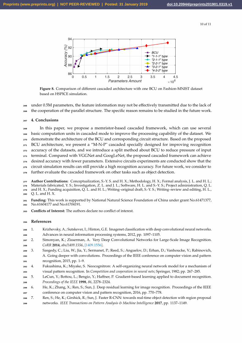
Figure 8 illustrates the relationship between the amount of model parameters and Fashion-MNIST258
recognition accuracy. The amount of convolution kernels in the BCU is between 5 to 32, 9×9 kernel size259
and 2×2 average pooling are applied. As shown in figure, the BCU can achieve 89.60% accuracy under260
0.5M parameters (when the amount of convolution kernels is 32). We tested the five cascaded type261
for their performance. It can be observed that as the number of parameters increases, the recognition262
accuracy of the network gradually increases. The “4-3-2" cascaded type provides 93.12% accuracy with263
4.15M parameters. It is worth noting that the accuracy of the BCU is better than“1-1-1" cascaded type264
Preprints (www.preprints.org) | NOT PEER-REVIEWED | Posted: 31 January 2019 Preprints (www.preprints.org) | NOT PEER-REVIEWED | Posted: 31 January 2019 doi:10.20944/preprints201901.0319.v1
10 of 11
0 0.5 1 1.5 2 2.5 3 3.5 4 4.5 Parameters Amount 106
86
88
90
92
94
Acc
urac
y (%
)
BCU "1-1-1" type "2-1-1" type "2-2-1" type "3-2-1" type "4-3-2" type
Figure 8. Comparison of different cascaded architecture with one BCU on Fashion-MNIST datasetbased on HSPICE simulation.
under 0.5M parameters, the feature information may not be effectively transmitted due to the lack of265
the cooperation of the parallel structure. The specific reason remains to be studied in the future work.266
4. Conclusions267
In this paper, we propose a memristor-based cascaded framework, which can use several268
basic computation units in cascaded mode to improve the processing capability of the dataset. We269
demonstrate the architecture of the BCU and corresponding circuit structure. Based on the proposed270
BCU architecture, we present a “M-N-P" cascaded specially designed for improving recognition271
accuracy of the datasets, and we introduce a split method about BCU to reduce pressure of input272
terminal. Compared with VGGNet and GoogLeNet, the proposed cascaded framework can achieve273
desired accuracy with fewer parameters. Extensive circuits experiments are conducted show that the274
circuit simulation results can still provide a high recognition accuracy. For future work, we consider to275
further evaluate the cascaded framework on other tasks such as object detection.276
Author Contributions: Conceptualization, S.-Y. S. and H. X.; Methodology, H. X.; Formal analysis, J. L. and H. L.;277
Materials fabricated, Y. S.; Investigation, Z. L. and J. L.; Software, H. L. and S.-Y. S.; Project administration, Q. L.278
and H. X.; Funding acquisition, Q. L. and H. L.; Writing–original draft, S.-Y. S.; Writing–review and editing, H. L.,279
Q. L. and H. X.280
Funding: This work is supported by National Natural Science Foundation of China under grant No.61471377,281
No.61604177 and No.61704191.282
Conflicts of Interest: The authors declare no conflict of interest.283
References284
1. Krizhevsky, A.; Sutskever, I.; Hinton, G.E. Imagenet classification with deep convolutional neural networks.285
Advances in neural information processing systems, 2012, pp. 1097–1105.286
2. Simonyan, K.; Zisserman, A. Very Deep Convolutional Networks for Large-Scale Image Recognition.287
CoRR 2014, abs/1409.1556, [1409.1556].288
3. Szegedy, C.; Liu, W.; Jia, Y.; Sermanet, P.; Reed, S.; Anguelov, D.; Erhan, D.; Vanhoucke, V.; Rabinovich,289
A. Going deeper with convolutions. Proceedings of the IEEE conference on computer vision and pattern290
recognition, 2015, pp. 1–9.291
4. Fukushima, K.; Miyake, S. Neocognitron: A self-organizing neural network model for a mechanism of292
visual pattern recognition. In Competition and cooperation in neural nets; Springer, 1982; pp. 267–285.293
5. LeCun, Y.; Bottou, L.; Bengio, Y.; Haffner, P. Gradient-based learning applied to document recognition.294
Proceedings of the IEEE 1998, 86, 2278–2324.295
6. He, K.; Zhang, X.; Ren, S.; Sun, J. Deep residual learning for image recognition. Proceedings of the IEEE296
conference on computer vision and pattern recognition, 2016, pp. 770–778.297
7. Ren, S.; He, K.; Girshick, R.; Sun, J. Faster R-CNN: towards real-time object detection with region proposal298
networks. IEEE Transactions on Pattern Analysis & Machine Intelligence 2017, pp. 1137–1149.299
Preprints (www.preprints.org) | NOT PEER-REVIEWED | Posted: 31 January 2019 Preprints (www.preprints.org) | NOT PEER-REVIEWED | Posted: 31 January 2019 doi:10.20944/preprints201901.0319.v1

11 of 11
8. Belhadj, B.; Joubert, A.; Li, Z.; Héliot, R.; Temam, O. Continuous real-world inputs can open up alternative300
accelerator designs. ACM SIGARCH Computer Architecture News. ACM, 2013, Vol. 41, pp. 1–12.301
9. Park, S.; Noh, J.; Choo, M.l.; Sheri, A.M.; Chang, M.; Kim, Y.B.; Kim, C.J.; Jeon, M.; Lee, B.G.; Lee,302
B.H.; others. Nanoscale RRAM-based synaptic electronics: toward a neuromorphic computing device.303
nanotechnology 2013, 24, 384009.304
10. Taur, Y.; Ning, T.H. Fundamentals of modern VLSI devices; Cambridge university press, 2013.305
11. Kim, B.; Lee, M.; Kim, J.; Kim, J.; Lee, J. Hierarchical Compression of Deep Convolutional Neural Networks306
on Large Scale Visual Recognition for Mobile Applications 2016.307
12. Chua, L. Memristor-the missing circuit element. IEEE Transactions on circuit theory 1971, 18, 507–519.308
13. Yakopcic, C.; Alom, M.Z.; Taha, T.M. Extremely Parallel Memristor Crossbar Architecture for Convolutional309
Neural Network Implementation. International Joint Conference on Neural Networks, 2017.310
14. Hu, M.; Strachan, J.P.; Li, Z.; Grafals, E.M.; Davila, N.; Graves, C.; Lam, S.; Ge, N.; Yang, J.J.; Williams, R.S.311
Dot-product engine for neuromorphic computing: programming 1T1M crossbar to accelerate matrix-vector312
multiplication. Proceedings of the 53rd annual design automation conference. ACM, 2016, p. 19.313
15. Shafiee, A.; Nag, A.; Muralimanohar, N.; Balasubramonian, R.; Strachan, J.P.; Hu, M.; Williams, R.S.;314
Srikumar, V. ISAAC: A convolutional neural network accelerator with in-situ analog arithmetic in crossbars.315
ACM SIGARCH Computer Architecture News 2016, 44, 14–26.316
16. Chi, P.; Li, S.; Xu, C.; Zhang, T.; Zhao, J.; Liu, Y.; Wang, Y.; Xie, Y. Prime: A novel processing-in-memory317
architecture for neural network computation in reram-based main memory. ACM SIGARCH Computer318
Architecture News. IEEE Press, 2016, Vol. 44, pp. 27–39.319
17. Li, B.; Wang, Y.; Wang, Y.; Chen, Y.; Yang, H. Training itself: Mixed-signal training acceleration for320
memristor-based neural network. Design Automation Conference (ASP-DAC), 2014 19th Asia and South321
Pacific. IEEE, 2014, pp. 361–366.322
18. Kim, S.; Ishii, M.; Lewis, S.; Perri, T.; BrightSky, M.; Kim, W.; Jordan, R.; Burr, G.; Sosa, N.; Ray, A.; others.323
NVM neuromorphic core with 64k-cell (256-by-256) phase change memory synaptic array with on-chip324
neuron circuits for continuous in-situ learning. Electron Devices Meeting (IEDM), 2015 IEEE International.325
IEEE, 2015, pp. 17–1.326
19. Yu, S.; Chen, P.Y.; Cao, Y.; Xia, L.; Wang, Y.; Wu, H. Scaling-up resistive synaptic arrays for neuro-inspired327
architecture: Challenges and prospect. Electron Devices Meeting (IEDM), 2015 IEEE International. IEEE,328
2015, pp. 17–3.329
20. Sun, S.; Li, J.; Li, Z.; Liu, H.; Li, Q.; Xu, H. Low-Consumption Neuromorphic Memristor Architecture Based330
on Convolutional Neural Networks. 2018 International Joint Conference on Neural Networks (IJCNN),331
2018, pp. 1–6. doi:10.1109/IJCNN.2018.8489441.332
21. Uppala, R.; Yakopcic, C.; Taha, T.M. Methods for reducing memristor crossbar simulation333
time. 2015 National Aerospace and Electronics Conference (NAECON), 2015, pp. 312–319.334
doi:10.1109/NAECON.2015.7443089.335
22. Xiao, H.; Rasul, K.; Vollgraf, R. Fashion-mnist: a novel image dataset for benchmarking machine learning336
algorithms. arXiv preprint arXiv:1708.07747 2017.337
23. Sun, Y.; Xu, H.; Wang, C.; Song, B.; Liu, H.; Liu, Q.; Liu, S.; Li, Q. A Ti/AlO x/TaO x/Pt analog synapse for338
memristive neural network. IEEE Electron Device Letters 2018, 39, 1298–1301.339
24. Sabour, S.; Frosst, N.; Hinton, G.E. Dynamic routing between capsules. Advances in Neural Information340
Processing Systems, 2017, pp. 3856–3866.341
Preprints (www.preprints.org) | NOT PEER-REVIEWED | Posted: 31 January 2019 Preprints (www.preprints.org) | NOT PEER-REVIEWED | Posted: 31 January 2019 doi:10.20944/preprints201901.0319.v1
![Modeling of the Memristor in SPICE Introduction In 1971, professor Chua predicted the existence of the fourth circuit element – memristor [3]. The memristor](https://img.pdfslide.us/doc/110x75/56649e3b5503460f94b2d7a3/modeling-of-the-memristor-in-spice-introduction-in-1971-professor-chua-predicted.jpg)


![Exponential Synchronization for Fractional-order Time ... · 01.03.2018 · resistor to develop a new neural networks that is memristor -based neural networks (MNN) [3 6]. In recent](https://img.pdfslide.us/doc/110x75/6062f4339e52cc3fcc6ea944/exponential-synchronization-for-fractional-order-time-01032018-resistor.jpg)