Embed Size (px)
Citation preview
A DESIGN OF A PLANT FOR MANUFACTURING /l;,
GAS ENGINES
BY
JAMES QUINTIN PETTIGREW
THESIS FOR THE DEGREE OF BACHELOR OF SCIENCE
IN MECHANICAL ENGINEERING
IN THE
COLLEGE OF ENGINEERING
OF THE
UNIVERSITY OF ILLINOIS
Presented June, 1909
brought to you by COREView metadata, citation and similar papers at core.ac.uk
provided by Illinois Digital Environment for Access to Learning and Scholarship Repository
UNIVERSITY OF ILLINOIS
.....JUNE..1,..... 1909
THIS IS TO CERTIFY THAT THE THESIS PREPARED UNDER MY SUPERVISION BY
... JAMES.QU1NTIN.PETTIGREW____ '.... .... ..... _
ENTITLED....A.DESIGN..OF A.PLANT..FOR.MANUFACTURIN'G.GAS..ENGINES...
IS APPROVED BY ME AS FULFILLING THIS PART OF THE REQUIREMENTS FOR THE
DEGREE QF BACHELOR OF SCIENCE______________________________________________ _
APPROVED
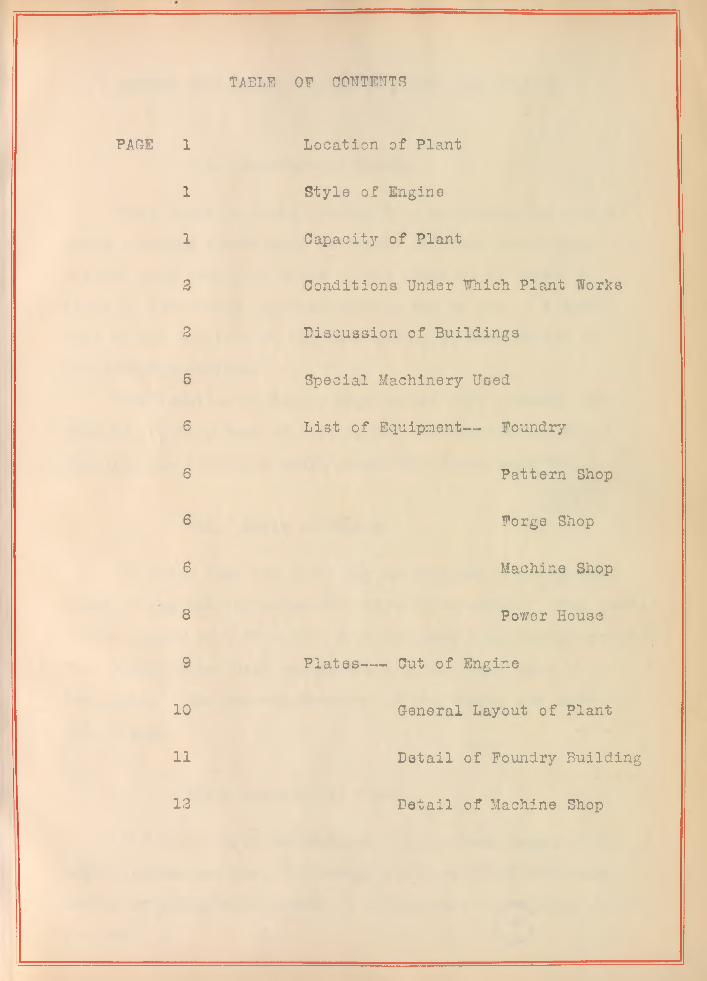
TABLE OP CONTENTS
PAGE 1
1
1
3
2
5
6
6
6
6
8
9
10
11
13
Location of Plant
Style of Engine
Capacity of Plant
Conditions Under Which Plant Works
Discussion of Buildings
Special Machinery Used
List of Equipment— Foundry
Pattern Shop
Forge Shop
Machine Shop
Power House
Plates--- Cut of Engine
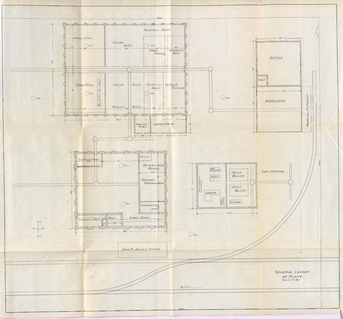
General Layout of Plant
Detail of Foundry Building
Detail of Machine Shop
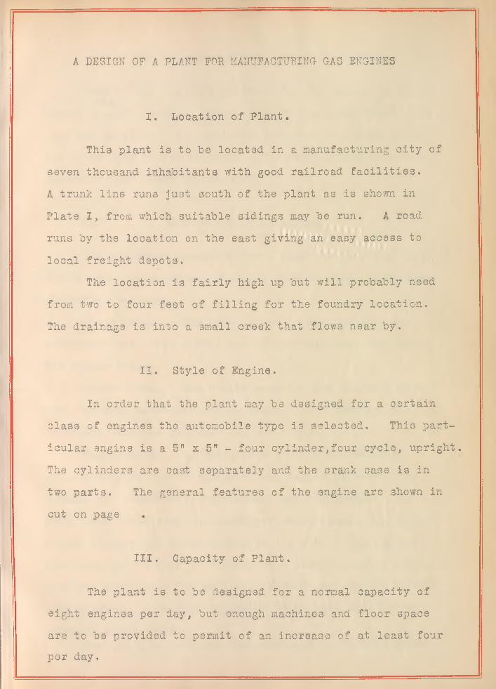
A DESIGN OF A PLANT FOR MANUFACTURING GAS ENGINES
I. Location of Plant.
This plant is to be located in a manufacturing city of seven thousand inhabitants with good railroad facilities.A trunk line runs just south of the plant as is shown in Plate I, from which suitable sidings may be run. A road runs by the location on the east giving an easy access to local freight depots.
The location is fairly high up but will probably need from two to four feet of filling for the foundry location.The drainage is into a small creek that flows near by.
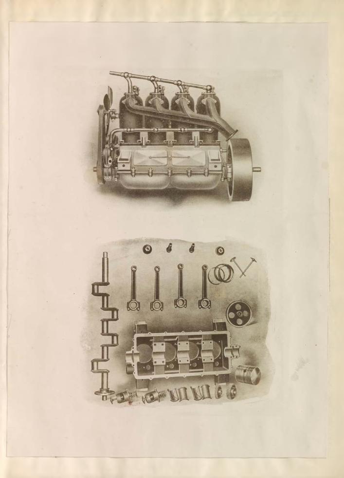
II. Style of Engine.
In order that the plant may be designed for a certain class of engines the automobile type is selected. This particular engine is a 5" x 5” - four cylinder,four cycle, upright. The cylinders are cast separately and the crank case is in two parts. The general features of the engine are shown in cut on page
III. Capacity of Plant.
The plant is to be designed for a normal capacity of eight engines per day, but enough machines and floor space are to be provided to permit of an increase of at least four per day.
2
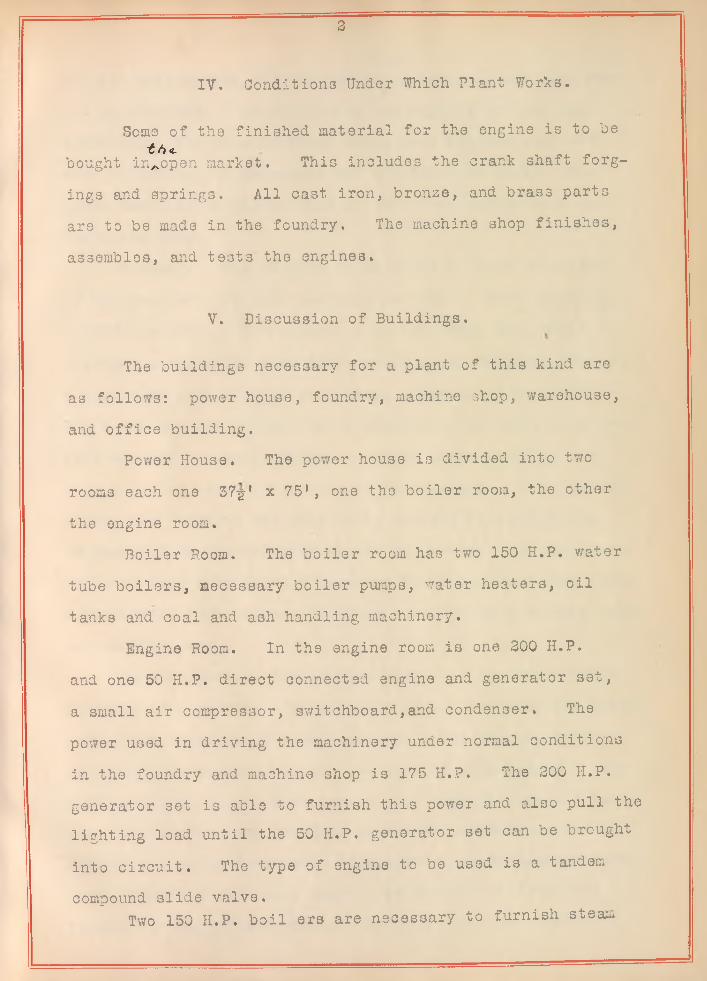
IV. Conditions Under Which Plant Works.
Borne of the finished material for the engine is to he £/}«.bought in^open market. This includes the crank shaft forg
ings- and springs. All cast iron, bronze, and brass parts are to be made in the foundry. The machine shop finishes, assembles, and tests the engines.
V. Discussion of Buildings.
The buildings necessary for a plant of this kind are as follows: power house, foundry, machine shop, warehouse,and office building.
Power House. The power house is divided into two rooms each one 37f' x 75’, one the boiler room, the other the engine room.
Boiler Room. The boiler room has two 150 H.P. water tube boilers, necessary boiler pumps, water heaters, oil tanks and coal and ash handling machinery.
Engine Room. In the engine room is one 200 H.P. and one 50 H.P. direct connected engine and generator set, a small air compressor, switchboard,and condenser. The po 7er used in driving the machinery under normal conditions in the foundry and machine shop is 175 H.P. The 200 H.P. generator set is able to furnish this power and also pull the lighting load until the 50 H.P. generator set can be brought into circuit. The type of engine to be used is a tandem compound slide valve.
Two 150 H.P. boil ers are necessary to furnish steam
3v
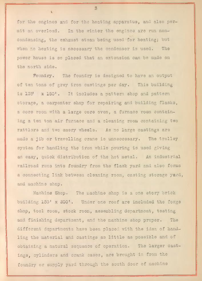
for the engines and for the heating apparatus, and also permit an overload. In the winter the engines are run noncondensing, the exhaust steam being used'for heating; but when no heating is necessary the condenser is used. The power house is so placed that an extension can be made on the north side.
Foundry. The foundry is designed to have an output of ten tons of grey iron castings per day. This building is 125’ x 150’ . It includes a pattern shop and pattern storage, a carpenter shop for repairing and building flasks, a core room with a large core oven, a furnace room containing a ten ton- air furnace ana a cleaning roora containing two rattlers and two emery wheels. As no large castings are made a jib or travelling crane is unnecessary. The trolley system for handling the iron while pouring is used giving an easy, quick distribution of the hot metal. An industrial railroad runs into foundry from the flask yard and also forms a connecting link between cleaning room, casting storage yard, and machine shop.
Machine Shop. The machine shop is a one story brick building 150* x 200’. Under one roof are included the forge shop, tool room, stock room, assembling department, testing and finishing department, and the machine shop proper. The different departments have been placed with the idea of handling the material and castings as little as possible and of obtaining a natural sequence of operation. The larger castings, cylinders and crank cases, are brought in from the foundry or supply yard through the south door of machine
4
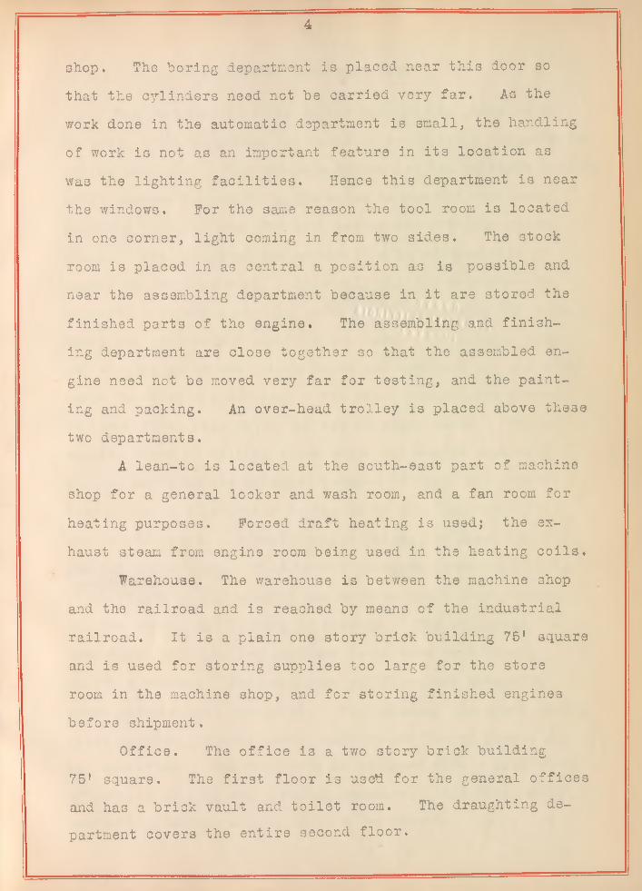
shop. The boring department is placed near this door so that the cylinders need not be carried very far. As the work done in the automatic department is small, the handling of work is not as an important feature in its location as wa3 the lighting facilities. Hence this department is near the windows. For the same reason the tool room is located in one corner, light coming in from two sides. The stock room is placed in as central a position as is possible and near the assembling department because in it are stored the finished parts of the engine. The assembling and finishing department are close together so that the assembled engine need not be moved very far for testing, and the painting and packing. An over-head trolley is placed above these two departments.
A lean-to is located at the south-east part of machine shop for a general locker and wash room, and a fan room for heating purposes. Forced draft heating is used; the exhaust steam from engine room being used in the heating coils.
Warehouse, The warehouse is between the machine shop and the railroad and is reached by means of the industrial railroad. It is a plain one story brick building 75’ square and is used for storing supplies too large for the store room in the machine shop, and for storing finished engines before shipment.
Office. The office is a two story brick building 75’ square. The first floor is used for the general offices and has a brick vault and toilet room. The draughting department covers the entire second floor.
5
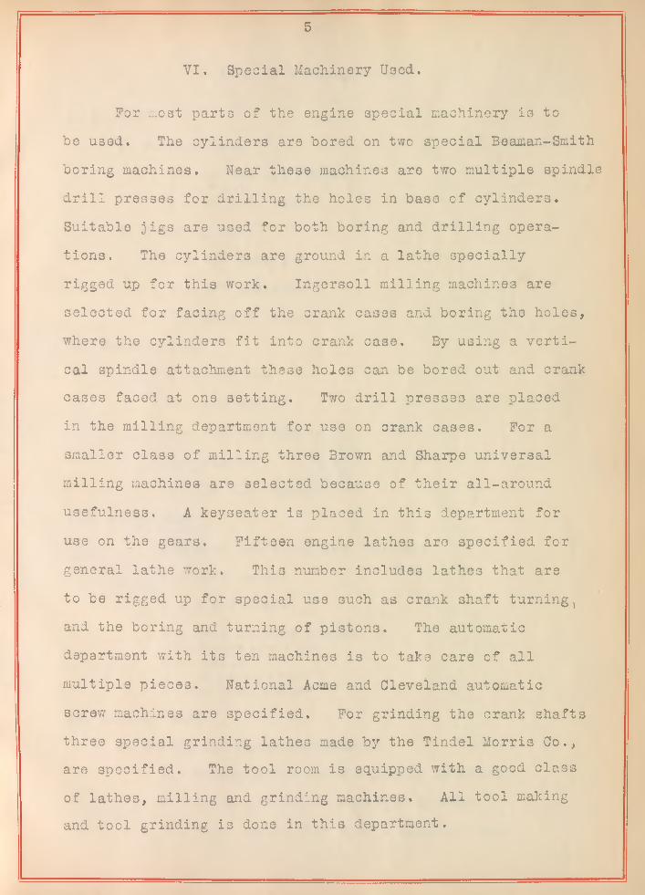
VI. Special Machinery Used,
For most parts of the engine special machinery is to he used. The cylinders are bored on two special Beaman-Smith boring machines. Near these machines are two multiple spindle drill presses for drilling the holes in base of cylinders. Suitable jigs are used for both boring and drilling operations. The cylinders are ground in a lathe specially rigged up for this work. Ingersoll milling machines are selected for facing off the crank cases and boring the holes, where the cylinders fit into crank case. By using a vertical spindle attachment these holes can be bored out and crank cases faced at one setting. Two drill presses are placed in the milling department for use on crank cases. For a smaller class of milling three Brown and Sharpe universal milling machines are selected because of their all-around usefulness. A keyseater is placed in this department for use on the gears. Fifteen engine lathes are specified for general lathe work. This number includes lathes that are to be rigged up for special use such as crank shaft turning, and the boring and turning of pistons. The automatic department with its ten machines is to take care of all multiple pieces. National Acme and Cleveland automatic screw machines are specified. For grinding the crank shafts three special grinding lathes made by the Tindel Morris Co., are specified. The tool room is equipped with a good class of lathes, milling and grinding machines. All tool making and tool grinding is done in this department.
6
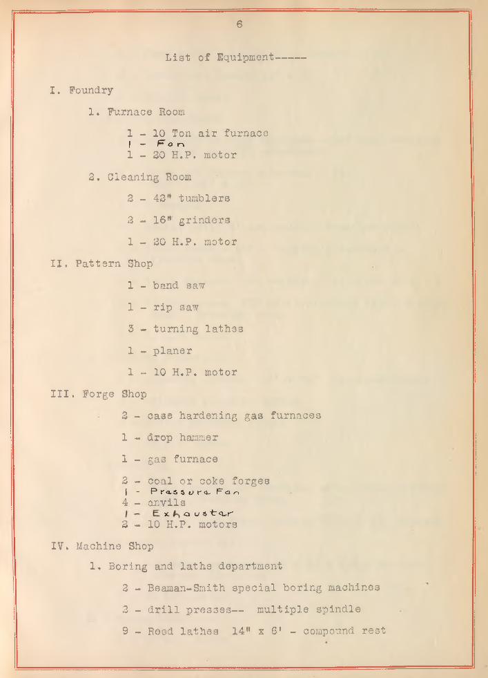
List of Equipment
I. Foundry1. Furnace Room
1 - 1 0 Ton air furnace1 — Fan1 - 2 0 H.P. motor
2. Cleaning Room2 - 42" tumblers2 - 16"' grinders 1 - 2 0 H.P. motor
II. Pattern Shop1 - band saw 1 - rip saw3 - turning lathes 1 - planer 1 - 1 0 H.P. motor
III. Forge Shop2 - case hardening gas furnaces 1 - drop hammer1 - gas furnace2 - coal or coke forges| - Pr<L3s«jra> F a 04 - anvils
I - Ex. ha u « tra.r'2 - 1 0 H.P. motors
IV. Machine Shop1. Boring and lathe department
2 - Bsaman-Smith special boring machines 2 - drill presses-- multiple spindle 9 - Reed lathes 14" x 6* - compound rest
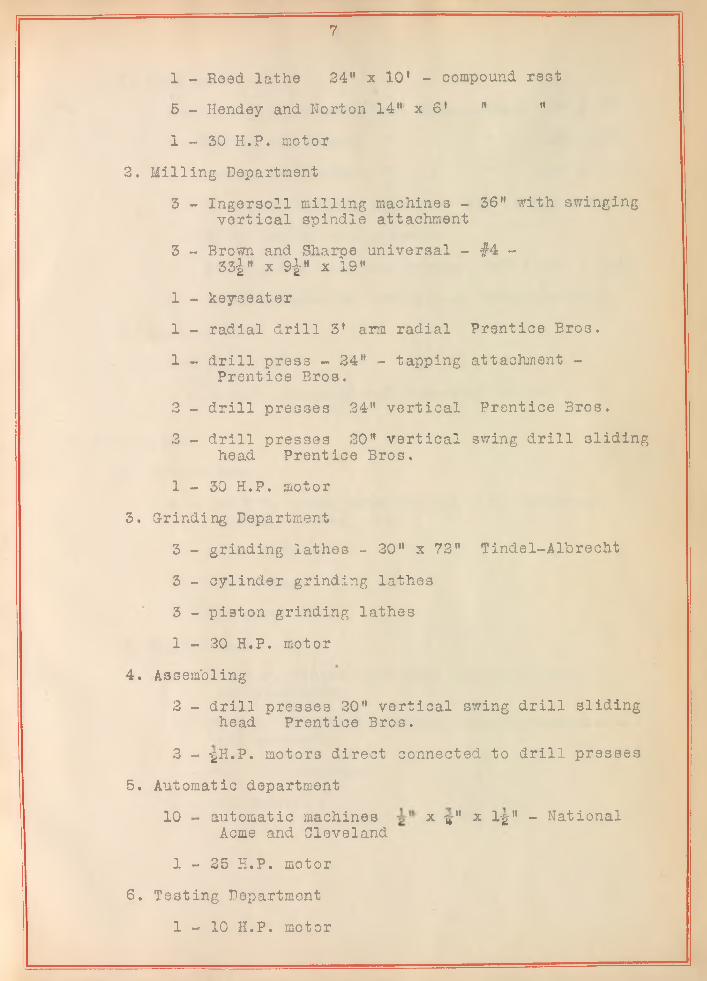
7
1 - Reed lathe 24" x 10' - compound rest 5 - Hendey and Norton 14"' x 6’ " "1 - 3 0 H.P. motor
3. Milling Department3 - Ingersoll milling machines - 36" with swinging
vertical spindle attachment3 - Brown and Sharpe universal - #4 -
33i" x 9-|" x 19"1 - keyseater1 - radial drill 3' arm radial Prentice Bros.1 - drill press - 34" - tapping attachment -
Prentice Bros.2 - drill presses 34" vertical Prentice Bros,2 - drill presses 20" vertical swing drill sliding
head Prentice Bros.1 - 3 0 H.P. motor
3. Grinding Department3 - grinding lathes - 30" x 72" Tindel-Albrecht 3 - cylinder grinding lathes3 - piston grinding lathes1 - 30 H.P. motor
4. Assembling2 - drill presses 30" vertical swing drill sliding
head Prentice Bros.3 - -gH.P. motors direct connected to drill presses
5. Automatic department10 - automatic machines x t»" x l-g" - National
Acme and Cleveland1 - 3 5 H.P. motor
6. Testing Department1 - 10 H.P. motor
8
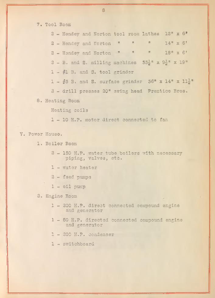
7. Tool Room2 - Hendey and Norton tool room lathes 12” x 6*2 - Hendey and Norton " " " 14” x gi2 - Hendey and Norton " ” ” 18” x 6'2 - B. and S. milling machines 33-|” x 9-?,” x 19"1 - #1 B. and S. tool grinder1 - #3 B. and S. surface grinder 36" x 14" x 11-|"2 - drill presses 20" swing head Prentice Bros.
8. Heating RoomHeating coils1 - 1 0 H.P. motor direct connected to fan
V. Power House.1. Boiler Room
2 - 150 H.P. water tube boilers with necessary piping, valves, etc.
1 - water heater2 - feed pumps 1 - oil pump
2. Engine Room1 - 200 H.P. direct connected compound engine
and generator1 - 5 0 H.P. directed connected compound engine
and generator1 - 300 H.P. condenser1 - switchboard
aj o=/J.b'-7<j
vu/<y<ystyg-
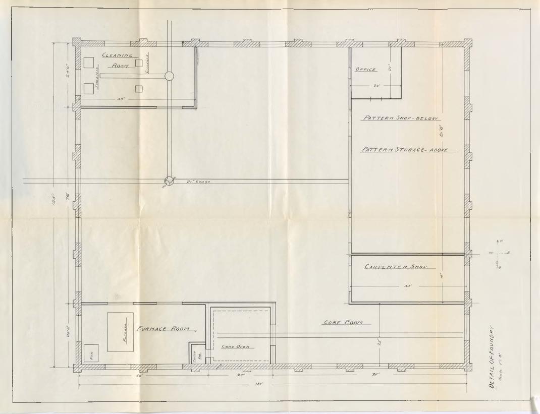
i)£TA / L OF
fOU
fiDR
Y