Embed Size (px)
Citation preview
23RD INTERNATIONAL SYMPOSIUM ON BALLISTICS TARRAGONA, SPAIN 16-20 APRIL 2007
853
A COMPARISON BETWEEN EXPERIMENT AND NUMERICAL
SIMULATION OF FABRIC BALLISTIC IMPACT
Yen, C-F, Scott, B, Dehmer, P. and Cheeseman, B. US Army Research Laboratory, Weapons and Materials Research Directorate, Aberdeen Proving Grounds, Md. 21005
This paper studies a single ply aramid fabric subject to the central impact of a fragment-simulating projectile. At the previous International Ballistic Symposium, two papers [1,2] were presented that studied this same configuration from different approaches. Yen[1] performed LS-Dyna [3] numerical simulations while Scott [2] used contemporary image analysis coupled with high speed digital video to measure full field surface strains and out of plane deformation of the backside of this fabric panel. This paper compares those simulation predictions directly with the displacement measurements. The agreement is less than perfect. Even though the simulation was performed with mesh resolution at the level of the yarn structure, there are many unknown aspects of the constitutive model and boundary conditions that could explain this disagreement. Two of these were briefly described in the Yen paper. This paper presents the results of a more extensive parametric variation of those items that are not independently known but still need to be specified for the execution of the finite element simulation. While friction between yarns was found to have limited effect, the greatest uncertainty seems to be associated with how to model the behavior of the yarn bundle itself. We present the results of these parametric numerical experiments and suggest the set of approximations that seem to best agree with the physical measurements.
INTRODUCTION
The design of “body armors” has classically followed extensive trial and error ballistic testing. While the mechanics of the impact loading of one-dimensional yarns is relatively well established following the pioneering works of Smith, et al. (4), the extension to those same one-dimensional yarns into real two dimensional fabric structures is less so. Roylance (5) had made significant advances using a direct numerical analysis where the fabric crossovers are modeled as pinned joints with yarns modeled as connecting bars. The model predictions are in general agreement with experimental observations of ballistic impact of nylon and aramid fabric panels. Despite the useful identification of the importance of some of the material properties of the reinforcement yarns, the use of this model for designing fabric armors has not been routine.
With the advent of modern computational hardware we can now relax some of the approximations imposed out of necessity in the past. Similar to the computational study of Shockey,et al [6], we model each individual yarn bundle, thereby allowing the interaction of the contact between yarns to be adjusted. Resolution demands are
ARMOUR PROTECTION AND WOUND BALLISTICS 854
significant, but with computer resources available today, these computational studies are now possible. Indeed, we can relax the usual smearing of several actual cross-over unit cells into fewer computational elements. We will apply solid or shell elements, however. This appears to be a significant assumption since what appears to be often a heterogeneous response, may not be properly modeled with continuum type material behavior. Computational predictions were then performed where we parametrically adjusted the values of coefficients of the constitutive models, resolution of the element formulation or the range of possible boundary conditions, hopefully bounding what was actually applied on the shot panel.
The experiments are not free from uncertainty either. In Scott [2] we presented measured displacement fields and calculated strain fields, based upon small displacement theory where deformation gradients are measured by monitoring relative motion between details on the surface of the fabric ply. We painted dots on the surface of the fabric, whose dimension was of the order of the filaments (11 microns in diameter) or larger. Displacements between these dots could represent strain along a particular filament or could simply identify relative motion between orthogonal yarns or filaments within a particular yarn. For this reason, we chose to compare the numerical predictions to something we knew we could measure without such uncertainty. We will focus on the out-of –plane deformation of the fabric layer. If phenomena related to fabric architecture were expected, they would be observed with the video method, depending of course on optical resolution limits.
INITIAL COMPARISON BETWEEN EXPERIMENT AND PREDICTIONS
Typical applications of textile armors utilize multiple layers of two-dimensional woven fabrics. Classic orientation of the initial fabric plane being orthogonal to the projectile trajectory results in out-of-plane deformation with a complex interaction of strain waves that spread out into three-dimensional space. If the fabric were to behave as a membrane, models have been published that give reasonable estimates of everything from deflection profiles to ballistic limit. Papers by Phoenix [7], Walker [8] and Scott [9] describe membrane approaches to predicting the capacity of the armor to arrest idealized fragments or determine the extent of deflection.
0
0.5
1
1.5
2
2.5
3
3.5
0 0.05 0.1 0.15 0.2 0.25 0.3 0.35 0.4 0.45 0.5
Time, msec
Vertic
al D
ispl
acem
ent,
cm
x=0cmx=1.2cmx=2.4cmx=3.6cmx=4.8cmExp. Max.
Comparison of predicted and measured transverse deflections
Figure 1. Comparison between measured and predicted deflection histories.
A comparison between experiment and numerical simulation of fabric ballistic impact 855
We are interested in relaxing most of the approximations for this membrane approach, and will attempt to model at the yarn bundle scale. It is clear from figure 1 that our initial attempts, using our best estimates of properties for these yarns, fall somewhat short of matching the experimental observations.
The out-of-plane deformation can be measured straightforwardly with the modern video equipment. We can measure the displacement of the fabric immediately beneath the projectile and at stable framing rates; determine the time between frames to quite accurate extent. Any error between the two estimates must be assigned to the computational approach. The initial set of assumptions in the study reported by Yen [1] yields a prediction of the peak deflection that is different in magnitude and timing from what was measured by Scott [2].
Assuming that we have the proper fragment weight and velocity, the computational method should provide an accurate balance of energy and momentum. The boundary conditions and constitutive models could influence the resulting deflection history even though the global properties should be conserved. It appears that the predicted response is more compliant (less stiff) than the actual response. Peak deflections are different by a factor of approximately 2.0. This is an excellent opportunity to adjust those parameters used in the LS-Dyna simulation that we really don’t have well determined. Not only can we get a feel for how the predictions vary with the values of input parameters and constitutive model form, but also we will see in what direction we need to adjust our assumptions for improved agreement. The remainder of this paper will describe our attempt to adjust those input parameters which we can’t independently determine and compare the modified predictions to the measured response. HETEROGENEOUS YARNS VERSES CONTINUUM ELEMENT
Fabrics do not always respond as ideally as we would prefer. The fabric construction involves the mechanical crossing of yarns with little bonding of the orthogonal yarns at the point of crossover. The repeating unit cell does not respond like an elastic shell or continuum element. The fabric responds to in-plane loading similar to the individual yarn, with little shear coupling until the independent yarns begin to interact with one another on their lateral surfaces. The shear response is dependent upon fabric architecture (cover factor, crimp density, end count, interply stitch pattern and the fabric style (plain, satin, twill, leno, etc). The interaction of crossing yarns is also dependent to some unknown extent upon the mechanical coupling along contact surfaces. Yarn spin finishes, coatings, and yarn bundle geometries can influence the friction that develops between the yarns or between the fabric plies. This frictional and contact coupling must somehow determine how a fabric can support in-plane shear stresses. It’s not even straightforward as to how to model an individual yarn. Figure 2 presents a photograph of edge of the fabric used in the experiment above. The
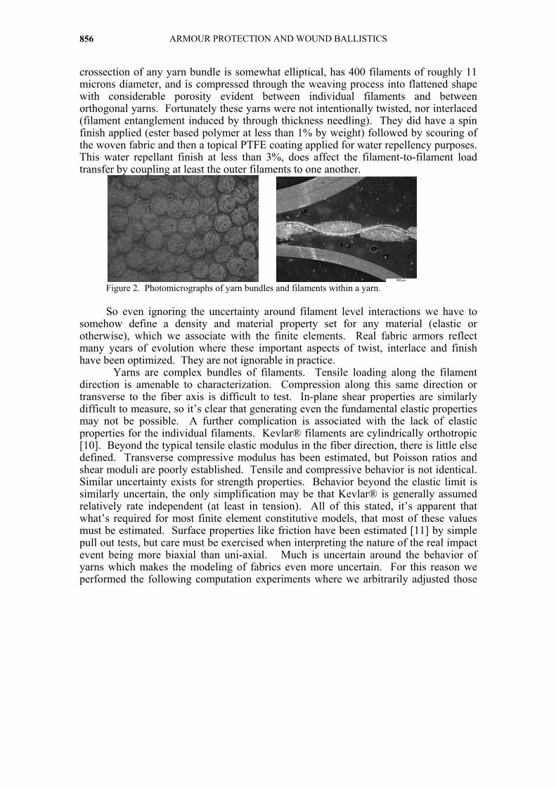
ARMOUR PROTECTION AND WOUND BALLISTICS 856
crossection of any yarn bundle is somewhat elliptical, has 400 filaments of roughly 11 microns diameter, and is compressed through the weaving process into flattened shape with considerable porosity evident between individual filaments and between orthogonal yarns. Fortunately these yarns were not intentionally twisted, nor interlaced (filament entanglement induced by through thickness needling). They did have a spin finish applied (ester based polymer at less than 1% by weight) followed by scouring of the woven fabric and then a topical PTFE coating applied for water repellency purposes. This water repellant finish at less than 3%, does affect the filament-to-filament load transfer by coupling at least the outer filaments to one another.
Figure 2. Photomicrographs of yarn bundles and filaments within a yarn.
So even ignoring the uncertainty around filament level interactions we have to
somehow define a density and material property set for any material (elastic or otherwise), which we associate with the finite elements. Real fabric armors reflect many years of evolution where these important aspects of twist, interlace and finish have been optimized. They are not ignorable in practice.
Yarns are complex bundles of filaments. Tensile loading along the filament direction is amenable to characterization. Compression along this same direction or transverse to the fiber axis is difficult to test. In-plane shear properties are similarly difficult to measure, so it’s clear that generating even the fundamental elastic properties may not be possible. A further complication is associated with the lack of elastic properties for the individual filaments. Kevlar® filaments are cylindrically orthotropic [10]. Beyond the typical tensile elastic modulus in the fiber direction, there is little else defined. Transverse compressive modulus has been estimated, but Poisson ratios and shear moduli are poorly established. Tensile and compressive behavior is not identical. Similar uncertainty exists for strength properties. Behavior beyond the elastic limit is similarly uncertain, the only simplification may be that Kevlar® is generally assumed relatively rate independent (at least in tension). All of this stated, it’s apparent that what’s required for most finite element constitutive models, that most of these values must be estimated. Surface properties like friction have been estimated [11] by simple pull out tests, but care must be exercised when interpreting the nature of the real impact event being more biaxial than uni-axial. Much is uncertain around the behavior of yarns which makes the modeling of fabrics even more uncertain. For this reason we performed the following computation experiments where we arbitrarily adjusted those
A comparison between experiment and numerical simulation of fabric ballistic impact 857
properties of standard elastic continuum shell elements which we had little independent knowledge. DETAILED COMPUTATIONAL SET-UP
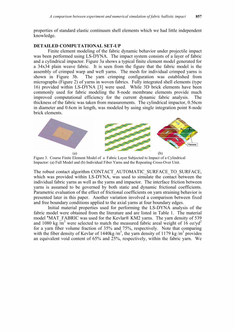
Finite element modeling of the fabric dynamic behavior under projectile impact was been performed using LS-DYNA. The impact system consists of a layer of fabric and a cylindrical impactor. Figure 3a shows a typical finite element model generated for a 34x34 plain weave fabric. It is seen from the figure that the fabric model is the assembly of crimped warp and weft yarns. The mesh for individual crimped yarns is shown in Figure 3b. The yarn crimping configuration was established from micrographs (Figure 2) of yarns in woven fabrics. Fully integrated shell elements (type 16) provided within LS-DYNA [3] were used. While 3D brick elements have been commonly used for fabric modeling the 8-node membrane elements provide much improved computational efficiency for the current dynamic fabric analysis. The thickness of the fabric was taken from measurements. The cylindrical impactor, 0.56cm in diameter and 0.6cm in length, was modeled by using single integration point 8-node brick elements.
Filaments
E11E22
Filaments
E11E22
Filaments
E11E22
(a) (b)
Figure 3. Course Finite Element Model of a Fabric Layer Subjected to Impact of a Cylindrical Impactor: (a) Full Model and (b) Individual Fiber Yarns and the Repeating Cross-Over Unit. The robust contact algorithm CONTACT_AUTOMATIC_SURFACE_TO_SURFACE, which was provided within LS-DYNA, was used to simulate the contact between the individual fabric yarns as well as the yarns and impactor. The interface friction between yarns is assumed to be governed by both static and dynamic frictional coefficients. Parametric evaluation of the effect of frictional coefficients on yarn straining behavior is presented later in this paper. Another variation involved a comparison between fixed and free boundary conditions applied to the axial yarns at four boundary edges.
Initial material properties used for performing the LS-DYNA analysis of the fabric model were obtained from the literature and are listed in Table 1. The material model *MAT_FABRIC was used for the Kevlar® KM2 yarns. The yarn density of 539 and 1080 kg /m3 were selected to match the measured fabric areal weight of 16 oz/yd2 for a yarn fiber volume fraction of 35% and 75%, respectively. Note that comparing with the fiber density of Kevlar of 1440kg /m3, the yarn density of 1179 kg /m3 provides an equivalent void content of 65% and 25%, respectively, within the fabric yarn. We
ARMOUR PROTECTION AND WOUND BALLISTICS 858
will later vary this input property as well. The associated yarn axial elastic moduli are also modified from the fiber modulus according to the selected fiber volume fractions. Table 1. Material Properties in LS-DYNA Input Format Used for (a) Kevlar® KM2 Yarns, 37% and 76% Fiber Volume Fractions, and 76% and (b) Steel Impactor
(a) *MAT_FABRIC(units: m,kg,pa,sec), 37% Fiber Volume Fratioin
mid ro e1 e2 e3 nu21 nu31 nu32 2 539.0 2.71E+10 2.71E+8 2.71E+8 0.001 0.001 0.001
g12 g23 g31 2.71+8 2.71E+8 2.71E+8
*MAT_FABRIC(units: m,kg,pa,sec), 75% Fiber Volume Fratioin mid ro e1 e2 e3 nu21 nu31 nu32 2 1080.0 5.43E+10 5.43E+8 5.43E+8 0.001 0.001 0.001
g12 g23 g31 5.43E+8 5.43E+8 5.43E+8
(b) *MAT_PLASTIC_KINEMATIC (units: m,kg,pa,sec)
mid ro e pr sigy etan beta
5 7850 2.07E+11 0.33 1.03E+09 3.45E+10 1
src
1
The transverse elastic moduli of yarns are assumed to be 100 times smaller than the axial properties to model the low transverse stiffness. Variations of Poisson ratio were applied. The material model *MAT_PLASTIC_KINEMATIC was used for the steel impactor. Elastic, rate independent behavior with identical response in compression and tension is enforced. Beyond yield, associated flow and perfect plasticity is applied. RESULTS
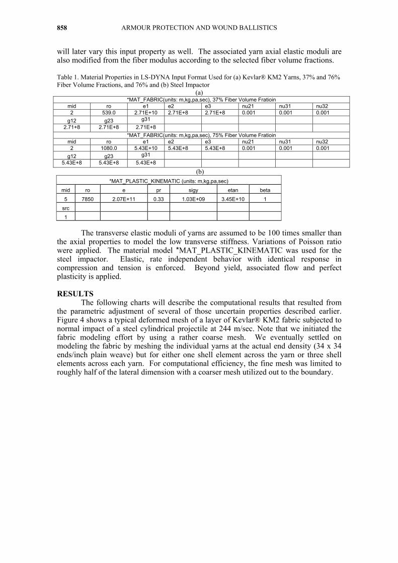
The following charts will describe the computational results that resulted from the parametric adjustment of several of those uncertain properties described earlier. Figure 4 shows a typical deformed mesh of a layer of Kevlar® KM2 fabric subjected to normal impact of a steel cylindrical projectile at 244 m/sec. Note that we initiated the fabric modeling effort by using a rather coarse mesh. We eventually settled on modeling the fabric by meshing the individual yarns at the actual end density (34 x 34 ends/inch plain weave) but for either one shell element across the yarn or three shell elements across each yarn. For computational efficiency, the fine mesh was limited to roughly half of the lateral dimension with a coarser mesh utilized out to the boundary.
A comparison between experiment and numerical simulation of fabric ballistic impact 859
Figure 4. Deformed Mesh of a 34x34 Kevlar Fabric Layer Subjected to Cylindrical Projectile at 244
m/sec at 0.3 msec. (lateral dimensions of 8 x 10 cm)
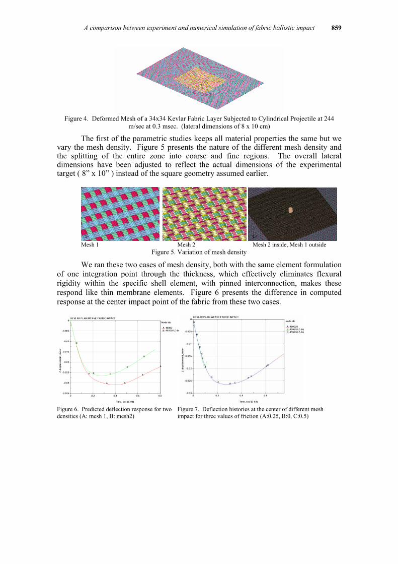
The first of the parametric studies keeps all material properties the same but we vary the mesh density. Figure 5 presents the nature of the different mesh density and the splitting of the entire zone into coarse and fine regions. The overall lateral dimensions have been adjusted to reflect the actual dimensions of the experimental target ( 8” x 10” ) instead of the square geometry assumed earlier.
Mesh 1 Mesh 2 Mesh 2 inside, Mesh 1 outside
Figure 5. Variation of mesh density
We ran these two cases of mesh density, both with the same element formulation of one integration point through the thickness, which effectively eliminates flexural rigidity within the specific shell element, with pinned interconnection, makes these respond like thin membrane elements. Figure 6 presents the difference in computed response at the center impact point of the fabric from these two cases.
Figure 6. Predicted deflection response for two Figure 7. Deflection histories at the center of different mesh densities (A: mesh 1, B: mesh2) impact for three values of friction (A:0.25, B:0, C:0.5)
ARMOUR PROTECTION AND WOUND BALLISTICS 860
Initially both configurations have similar response. Neither seems to slow the rate of deflection towards what is required for better agreement with the experiment. The finer mesh does reduce the magnitude of the peak deflection more than the coarse mesh but the time of rebound is reduced. Referring back to figure 1, this sole adjustment to one uncertain parameter would not resolve the difference with the measurement.
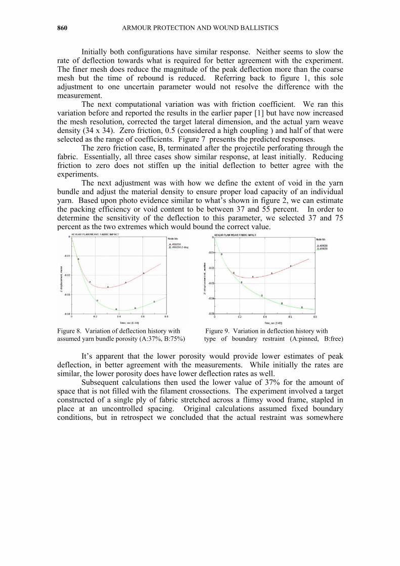
The next computational variation was with friction coefficient. We ran this variation before and reported the results in the earlier paper [1] but have now increased the mesh resolution, corrected the target lateral dimension, and the actual yarn weave density (34 x 34). Zero friction, 0.5 (considered a high coupling ) and half of that were selected as the range of coefficients. Figure 7 presents the predicted responses. The zero friction case, B, terminated after the projectile perforating through the fabric. Essentially, all three cases show similar response, at least initially. Reducing friction to zero does not stiffen up the initial deflection to better agree with the experiments. The next adjustment was with how we define the extent of void in the yarn bundle and adjust the material density to ensure proper load capacity of an individual yarn. Based upon photo evidence similar to what’s shown in figure 2, we can estimate the packing efficiency or void content to be between 37 and 55 percent. In order to determine the sensitivity of the deflection to this parameter, we selected 37 and 75 percent as the two extremes which would bound the correct value.
Figure 8. Variation of deflection history with Figure 9. Variation in deflection history with assumed yarn bundle porosity (A:37%, B:75%) type of boundary restraint (A:pinned, B:free)
It’s apparent that the lower porosity would provide lower estimates of peak deflection, in better agreement with the measurements. While initially the rates are similar, the lower porosity does have lower deflection rates as well.
Subsequent calculations then used the lower value of 37% for the amount of space that is not filled with the filament crossections. The experiment involved a target constructed of a single ply of fabric stretched across a flimsy wood frame, stapled in place at an uncontrolled spacing. Original calculations assumed fixed boundary conditions, but in retrospect we concluded that the actual restraint was somewhere
A comparison between experiment and numerical simulation of fabric ballistic impact 861
between pinned and free. We selected these two conditions as the limiting extremes of the actual boundary conditions applied in the comparable experiment.
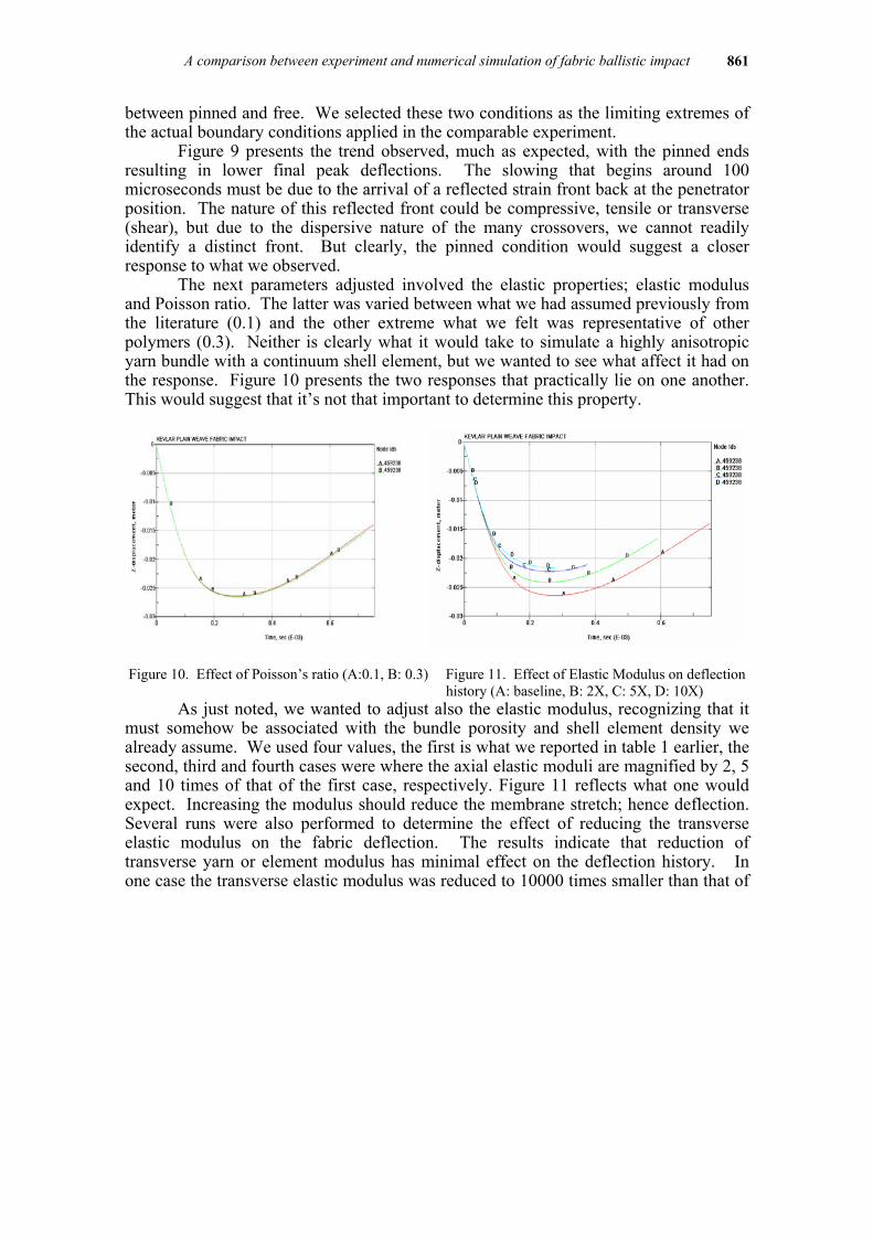
Figure 9 presents the trend observed, much as expected, with the pinned ends resulting in lower final peak deflections. The slowing that begins around 100 microseconds must be due to the arrival of a reflected strain front back at the penetrator position. The nature of this reflected front could be compressive, tensile or transverse (shear), but due to the dispersive nature of the many crossovers, we cannot readily identify a distinct front. But clearly, the pinned condition would suggest a closer response to what we observed.
The next parameters adjusted involved the elastic properties; elastic modulus and Poisson ratio. The latter was varied between what we had assumed previously from the literature (0.1) and the other extreme what we felt was representative of other polymers (0.3). Neither is clearly what it would take to simulate a highly anisotropic yarn bundle with a continuum shell element, but we wanted to see what affect it had on the response. Figure 10 presents the two responses that practically lie on one another. This would suggest that it’s not that important to determine this property.
Figure 10. Effect of Poisson’s ratio (A:0.1, B: 0.3) Figure 11. Effect of Elastic Modulus on deflection history (A: baseline, B: 2X, C: 5X, D: 10X)
As just noted, we wanted to adjust also the elastic modulus, recognizing that it must somehow be associated with the bundle porosity and shell element density we already assume. We used four values, the first is what we reported in table 1 earlier, the second, third and fourth cases were where the axial elastic moduli are magnified by 2, 5 and 10 times of that of the first case, respectively. Figure 11 reflects what one would expect. Increasing the modulus should reduce the membrane stretch; hence deflection. Several runs were also performed to determine the effect of reducing the transverse elastic modulus on the fabric deflection. The results indicate that reduction of transverse yarn or element modulus has minimal effect on the deflection history. In one case the transverse elastic modulus was reduced to 10000 times smaller than that of
ARMOUR PROTECTION AND WOUND BALLISTICS 862
the baseline case. However the solution became unstable as the transverse modulus approached zero.
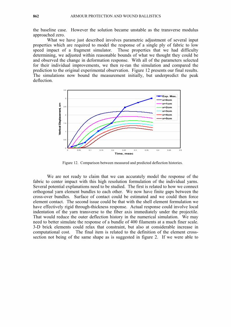
What we have just described involves parametric adjustment of several input properties which are required to model the response of a single ply of fabric to low speed impact of a fragment simulator. Those properties that we had difficulty determining, we adjusted within reasonable bounds of what we thought they could be and observed the change in deformation response. With all of the parameters selected for their individual improvements, we then re-ran the simulation and compared the prediction to the original experimental observation. Figure 12 presents our final results. The simulations now bound the measurement initially, but underpredict the peak deflection.
Figure 12. Comparison between measured and predicted deflection histories.
We are not ready to claim that we can accurately model the response of the fabric to center impact with this high resolution formulation of the individual yarns. Several potential explanations need to be studied. The first is related to how we connect orthogonal yarn element bundles to each other. We now have finite gaps between the cross-over bundles. Surface of contact could be estimated and we could then force element contact. The second issue could be that with the shell element formulation we have effectively rigid through-thickness response. Actual response could involve local indentation of the yarn transverse to the fiber axis immediately under the projectile. That would reduce the outer deflection history in the numerical simulation. We may need to better simulate the response of a bundle of 400 filaments at a much finer scale. 3-D brick elements could relax that constraint, but also at considerable increase in computational cost. The final item is related to the definition of the element cross-section not being of the same shape as is suggested in figure 2. If we were able to
0
0.5
1
1.5
2
2.5
3
3.5
0 0.05 0.1 0.15 0.2 0.25 0.3 0.35 0.4 0.45 0.5
Time, msec
Vertic
al D
ispl
acem
ent,
cm
Exp. Max.x=0cmx=1cmx=2cmx=3cmx=4cmx=5cm

A comparison between experiment and numerical simulation of fabric ballistic impact 863
define an elliptical cross-section, that could help define the nature of the contact between overlapping yarns. We need to also verify the calibration of the experimental results before we can conclusively blame the computational predictions. SUMMARY AND CONCLUSIONS We performed a series of parametric computational experiments with fabrics modeled much like they are constructed. The cross-over geometry of yarn bundles included the frictional coupling between yarns in contact. We performed simulations with varying input parameters, reflecting our uncertainty of those values. Unfortunately, we have not yet achieved the degree of agreement we would have liked. Part of this disparity may be accommodated by repeating the experiment several times and using instead the average response. The experimental variation may very well encompass the numerical simulation. We can’t claim to be able to model the deformation history, accurately, although relative trends have been identified and seem to agree with design experience.
The practical importance of this study will be understood when we apply these observed trends to modifications of real fabric armor design parameters like fabric construction and surface finish. It’s quite possible that the performance of fabric based body armor or fabric reinforced composite armor could be improved following application of lessons learned from these ongoing computational studies. REFERENCES 1 Yen, C-F and Scott, B. R., “Analytic Design Trends of Fabric Armor”, Proceedings of the 22nd Int. Symp. on Ballistics, Vancouver, Nov. 2005. 2. Scott, B, Dehmer, P and Schmidt, T, “Time Resolved Observation of the Deformation and Surface Strain of a Textile Fabric Subject to Ballistic Impact”, Proceedings of the 22nd Int. Symp. on Ballistics, Vancouver, Nov. 2005. 3. Hallquist, J. O, “LS-DYNA User’s Manual, Nonlinear Dynamic Analysis of Structures”, Livermore Software Technology Company, May 1999. 4. Smith, J.C., McCrackin, F. L, and Schiefer, H. F, “Stress-Strain Relationships in Yarns Subjected to Rapid Impact Loading. Part V: Wave Propagation in Long Textile Yarns Impacted Transversely”, Textile Research Journal, Vol. 28, 1958, 288-302. 5. Roylance, D., Wilde, A. and Tocci, G., “Ballistic Impact of Textile Structures”, Proceedings of the Army Symposium on Solid Mechanics, Oct 1972. 6. Shockey, D. A, Erlich, D. C, and Simons, J. W, “Lightweight Fragment Barriers For Commercial Aircraft”, Proceedings of the 18th Int. Symp. on Ballistics, San Antonio, November, 1999. 7. Phoenix, S. L. and Porwal, P.K, “A New Membrane Model for the Ballistic Impact Response and V50 Performance of Multi-Ply Fibrous Systems”, Int. Journal of Solids and Structures, 40, (2003) pp. 6723 8. Walker, J.D, “Constitutive Model for Fabrics with Explicit Static Solution and Ballistic Limit”, Proceedings of the 18th International Symposium of Ballistics, San Antonio, 1999, pp 1231-1239.

ARMOUR PROTECTION AND WOUND BALLISTICS 864
9. Scott, B, “ The Penetration of Compliant Laminates by Compact Projectiles”, Proceedings of the 18th International Ballistics Symposium, San Antonio, Technomic, Lancaster, PA., Nov 1999. 10. Yang, H. “Kevlar aromatic fiber”, John Wiley, 1997 11. Duan, Y., Keefe, M., Bogetti, T.A., and Cheeseman, B.A, “Modeling Friction Effects on the Ballistic Impact Behavior of a Single-ply High-strength Fabric,” International Journal of Impact Engineering, Vol. 31, 2005, pp. 996-1012.