Embed Size (px)
Citation preview
Composite Structures 116 (2014) 661–669
Contents lists available at ScienceDirect
Composite Structures
journal homepage: www.elsevier .com/locate /compstruct
Effects of fabric target shape and size on the V50 ballistic impact responseof soft body armor
http://dx.doi.org/10.1016/j.compstruct.2014.06.0020263-8223/� 2014 Elsevier Ltd. All rights reserved.
⇑ Corresponding author. Tel.: +1 (213)740 1634.E-mail address: [email protected] (S. Nutt).
Gaurav Nilakantan, Steven Nutt ⇑Mork Family Department of Chemical Engineering and Materials Science, M.C. Gill Composites Center, University of Southern California, Los Angeles, CA 90089, USA
a r t i c l e i n f o
Article history:Available online 13 June 2014
Keywords:Aramid fiberFabricsBallistic impactFinite element analysisV50 velocity
a b s t r a c t
The effects of target shape and size on the V50 ballistic impact response of non-backed woven aramid fab-rics is studied by considering 4-sided, circular, and diamond clamped fabrics with cross-sectional areasvarying between 5 cm2 and 525 cm2. The fabric targets show an initial very sharp rise in V50 velocitywhich then plateaus out with increasing fabric areas. At impact velocities around the V50 velocity for eachclamped fabric shape, there is a critical fabric size beyond which the projectile residual kinetic energyshows a sharp jump in magnitude, which continues to grow with increasing fabric sizes. Regardless offabric size, all impacts show sensitivity to the precise projectile impact location with yarn-based impactsgenerally resulting in greater energy dissipations than gap-based impacts. Over the range of target sizesconsidered, the V50 velocities of the circular and diamond clamped fabrics were very similar to each otherand higher than the 4-sided clamped fabric targets.
� 2014 Elsevier Ltd. All rights reserved.
1. Introduction
The ballistic impact behavior of fabric-based structures used insoft body armor is influenced by many obvious parameters such asthe geometry, material, and architecture of the fabric and its con-stituents. Geometrical parameters include the filament (i.e. fiber)diameter, filament packing, and yarn denier; material parametersinclude the strength, stiffness, and frictional characteristics;architectural parameters include the weave tightness and yarncrimp. These parameters have been the focus of many experimen-tal and numerical studies [1]. However there are several othernon-obvious factors to consider when assessing and comparingthe ballistic impact performances of these fabric-based structures.For example, keeping the choice of fabric material and architectureconstant, the manner in which the experimental testing isconducted can have a significant effect on the estimated fabricV50 velocity. The V50 velocity is defined as the projectile impactvelocity that has a 50% probability of completely penetratingthrough the target. To demonstrate this, we had shown in a previ-ous study [2] that for a given fabric target area, the shape of thefabric target whether fully or partially clamped had an importanteffect on the fabric V50 velocity. Circular and diamond clampedfabrics resulted in similar fabric V50 velocities that were higherthan 4-sided clamped fabrics and much higher than 2-sided
clamped fabrics, with corner clamped fabrics showing the poorestoverall performance. One reason was that circular and diamondclamped fabrics resulted in a more efficient distribution of theexposed fabric area compared to 4-sided clamped fabrics, as theyconcentrated more fabric material around the impact region whichsees the highest levels of deformation, stress, and energy dissipa-tion, and lesser fabric material at far-field regions that see littleto no activity. It should be noted that because the fabric area waskept constant, each of the 4-sided, circular, and diamond clampedfabrics had different principal yarn lengths. The principal yarnsrefer to the yarns around the impact region that are in contact withthe projectile during the impact event. The location of the principalyarns is exemplified later in Fig. 5d.
This two-part study extends upon our previous study [2]. Thefirst part investigates the relative effect of the length of the princi-pal yarns on the fabric V50 impact response compare to the overallexposed fabric area. The principal yarns experience the highestlevels of stress and deformation that rapidly drop off in theneighboring yarns with distance away from the impact site.Consequently the principal yarns account for the highest yarninternal energies. The second part of this study investigates howthe fabric V50 velocity changes as a function of the exposed fabricarea for various fully clamped fabric target configurations.
Other experimental and numerical studies have also shown thedependence of the fabric V50 velocity and zone of mixed results(ZMR) on the boundary conditions, clamping pressures, boundaryslippage, presence of backing, and target size [3–5]. Obviously
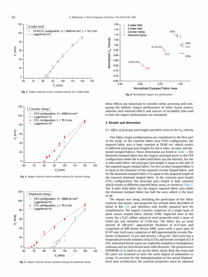
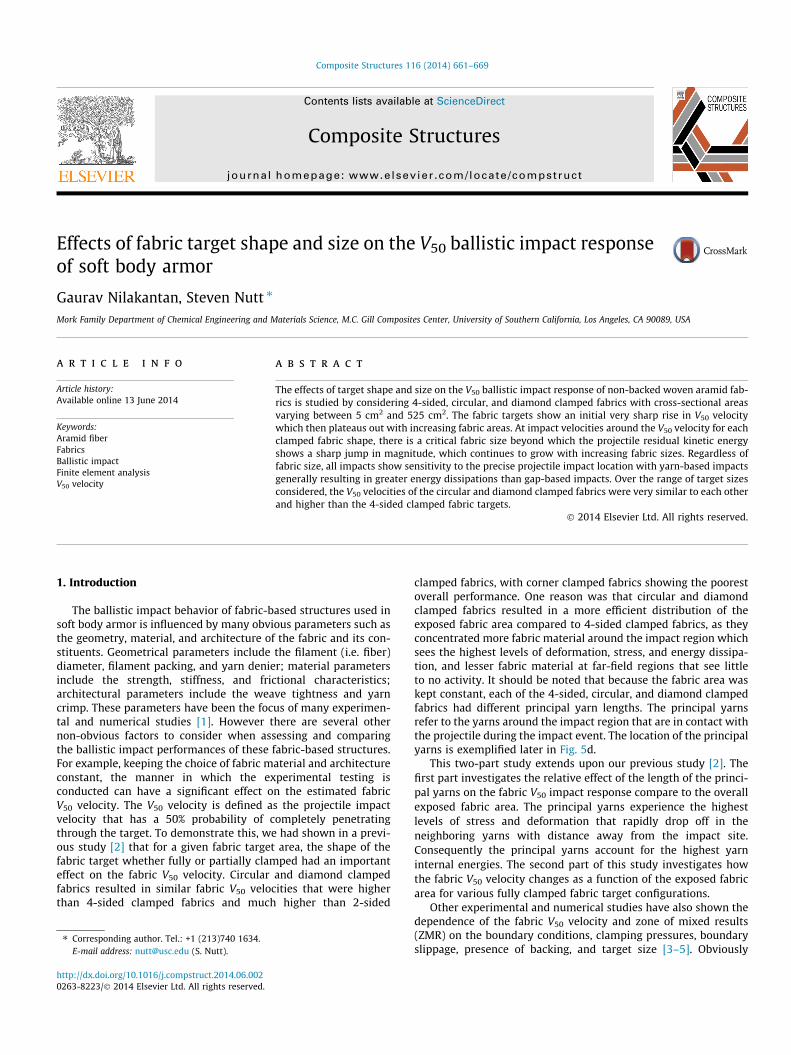
Fig. 1. Impact velocity versus residual velocity for 4-sides held.
Fig. 2. Impact velocity versus residual velocity for circular clamp.
Fig. 3. Impact velocity versus residual velocity for diamond clamp.
Fig. 4. Normalized impact test performance.
662 G. Nilakantan, S. Nutt / Composite Structures 116 (2014) 661–669
these effects are important to consider when assessing and com-paring the ballistic impact performance of fabric based armors,wherein such external effects and sources of variability that tendto bias the impact performance are unwanted.
2. Results and discussion
2.1. Effect of principal yarn length and fabric area on the V50 velocity
Two fabric target configurations are considered in the first partof the study. In the constant fabric area (CFA) configuration, theexposed fabric area is kept constant at 58.06 cm2 which resultsin different principal yarn lengths for the 4-sides, circular, and dia-mond clamped fabrics. These dimensions are listed in Table 1. Thediamond clamped fabric has the longest principal yarns in the CFAconfiguration while the 4-sides held fabric has the shortest. For the4-sides held fabric, the principal yarn length is equal to the side ofthe exposed square shaped fabric. For the circular clamped fabric itis equal to the diameter of the exposed circular shaped fabric, andfor the diamond clamped fabric it is equal to the diagonal length ofthe exposed diamond shaped fabric. In the constant yarn length(CYL) configuration, the principal yarn length is kept constantwhich results in different exposed fabric areas, as shown in Table 1.The 4-sides held fabric has the largest exposed fabric area whilethe diamond clamped fabric has half the area, which is the leastof all.
The impact test setup, including the particulars of the fabricmaterial and weave, and projectile has already been described indetail in Ref. [2], and therefore only briefly repeated here forcompleteness. The impact scenario comprises of a single layer ofplain weave aramid fabric (Kevlar S706) impacted once at thecenter by a 0.22 caliber spherical steel projectile with a mass of0.692 gm and diameter of 5.556 mm. The fabric has an arealdensity of 180 g/m2, approximate thickness of 0.23 mm, andcomprised of 600 denier Kevlar KM2 yarns with a yarn span of0.747 mm. Each yarn comprises of 400 approximately circular fila-ments of diameter 12 lm and density 1.44 g/cm3. Each yarn has alongitudinal tensile modulus of 82.6 GPa and tensile strength of 3.4GPa. Individual Kevlar yarns are explicitly modeled as homogenouscontinua and are discretized with solid elements. The preprocessorDYNAFAB [6] is used to set up the fabric mesh. Both the warp andfill yarns are assumed to have the same degree of undulation orcrimp. To account for the homogenization of the actual filament-level yarn architecture, the material properties must be adjusted
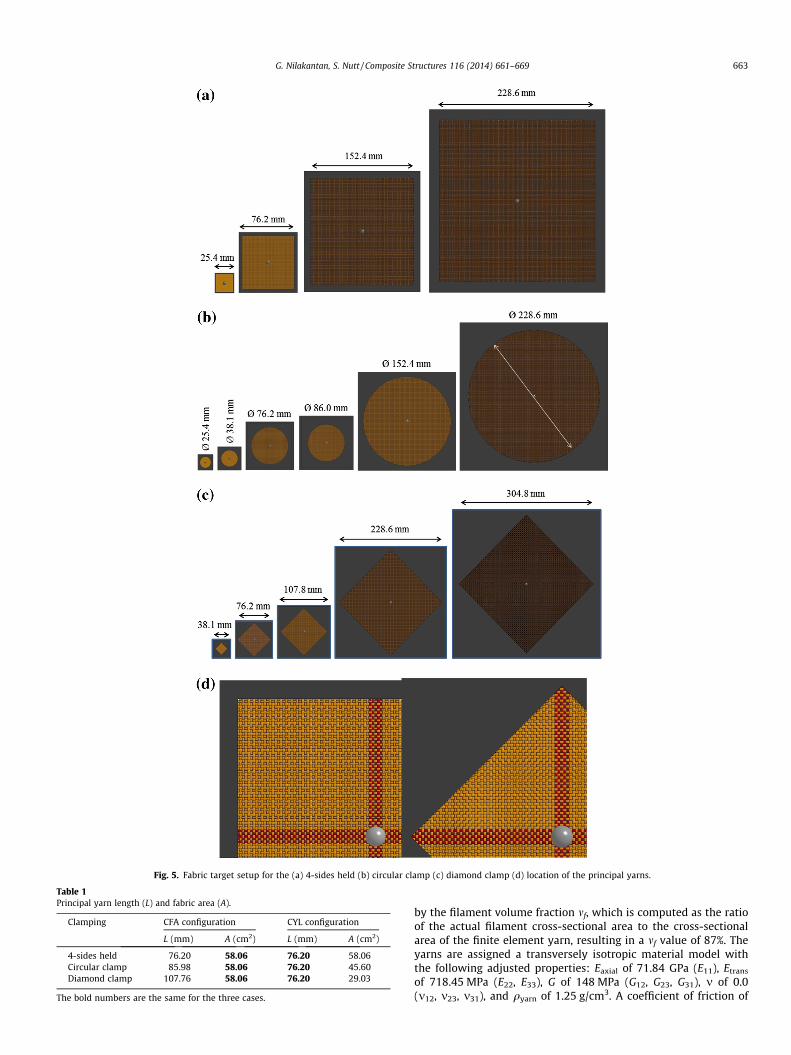
Fig. 5. Fabric target setup for the (a) 4-sides held (b) circular clamp (c) diamond clamp (d) location of the principal yarns.
Table 1Principal yarn length (L) and fabric area (A).
Clamping CFA configuration CYL configuration
L (mm) A (cm2) L (mm) A (cm2)
4-sides held 76.20 58.06 76.20 58.06Circular clamp 85.98 58.06 76.20 45.60Diamond clamp 107.76 58.06 76.20 29.03
The bold numbers are the same for the three cases.
G. Nilakantan, S. Nutt / Composite Structures 116 (2014) 661–669 663
by the filament volume fraction mf, which is computed as the ratioof the actual filament cross-sectional area to the cross-sectionalarea of the finite element yarn, resulting in a mf value of 87%. Theyarns are assigned a transversely isotropic material model withthe following adjusted properties: Eaxial of 71.84 GPa (E11), Etrans
of 718.45 MPa (E22, E33), G of 148 MPa (G12, G23, G31), m of 0.0(m12, m23, m31), and qyarn of 1.25 g/cm3. A coefficient of friction of
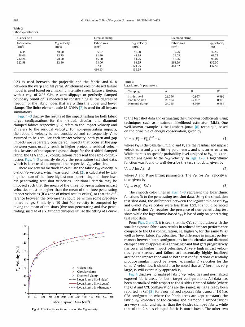
Table 2Fabric V50 velocities.
4-sides held Circular clamp Diamond clamp
Fabric area V50 velocity Fabric area V50 velocity Fabric area V50 velocity(cm2) (m/s) (cm2) (m/s) (cm2) (m/s)
6.45 40.00 5.07 40.00 7.26 42.5058.06 83.75 11.40 41.25 29.03 68.75
232.26 120.00 45.60 81.25 58.06 90.00522.58 132.50 58.06 91.25 261.29 132.50
182.41 121.25 464.52 137.50410.43 136.25
Table 3Logarithmic fit parameters.
Clamping A B R2
4-sides held 21.556 –0.957 0.996Circular clamp 23.904 –7.067 0.976Diamond clamp 24.225 –8.069 0.989
664 G. Nilakantan, S. Nutt / Composite Structures 116 (2014) 661–669
0.23 is used between the projectile and the fabric, and 0.18between the warp and fill yarns. An element erosion-based failuremodel is used based on a maximum tensile stress failure criterion,with a rfail of 2.95 GPa. A zero slippage or perfectly clampedboundary condition is modeled by constraining all the degrees offreedom of the fabric nodes that are within the upper and lowerclamps. The finite element code LS-DYNA [7] is used for all impactsimulations.
Figs. 1–3 display the results of the impact testing for both fabrictarget configurations for the 4-sided, circular, and diamondclamped fabrics respectively. Vi refers to the impact velocity andVr refers to the residual velocity. For non-penetrating impacts,the rebound velocity is not considered and consequently Vr isassumed to be zero. For each impact velocity, both yarn and gapimpacts are separately considered. Impacts that occur at the gapbetween yarns usually result in higher projectile residual veloci-ties. Because of the square exposed shape for the 4-sided clampedfabric, the CFA and CYL configurations represent the same configu-ration. Figs. 1–3 primarily display the penetrating test shot data,which is later used to compute the respective V50 velocities.
There are several methods to calculate the fabric V50 velocity. A6-shot V50 velocity, which was used in Ref. [2], is calculated by tak-ing the mean of the three highest non-penetrating and three low-est penetrating test shot velocities. Additional criteria may beimposed such that the mean of the three non-penetrating impactvelocities must be higher than the mean of the three penetratingimpact velocities (if a zone of mixed results exists), or that the dif-ference between the two means should be within some predeter-mined range. Similarly a 10-shot V50 velocity is computed bytaking the mean of ten shots (five non-penetrating and five pene-trating) instead of six. Other techniques utilize the fitting of a curve
Fig. 6. Effect of fabric target size on the V50 velocity.
to the test shot data and estimating the unknown coefficients usingtechniques such as maximum likelihood estimator (MLE). Onewell-known example is the Lambert–Jonas [8] technique, basedon the principle of energy conservation, given by
Vr ¼ aðVpi � Vp
BLÞ1=p þ e ð1Þ
where VBL is the ballistic limit, Vr and Vs are the residual and impactvelocities, a and p are fitting parameters, and e is an error term.While there is no specific probability level assigned to VBL, it is con-sidered analogous to the V50 velocity. In Figs. 1–3, a logarithmicfunction was found to well describe the test shot data, given by
Vr ¼ A lnðViÞ þ B ð2Þ
where A and B are fitting parameters. The V50 (or VBL) velocity isthen given by
V50 ¼ expð�B=AÞ ð3Þ
The smooth color lines in Figs. 1–3 represent the logarithmicfunctions fit to the penetrating test shot data. Using the simulationtest shot data, the differences between the logarithmic-based V50
and 6-shot V50 velocities were less than 1.5%. It should be notedthat the 6-shot V50 requires the presence of non-penetrating testshots while the logarithmic-based V50 is based only on penetratingtest shot data.
From Figs. 2 and 3, it is seen that the CYL configuration with thesmaller exposed fabric area results in reduced impact performancecompare to the CFA configuration, i.e. higher Vr for the same Vi, aswell as lower fabric V50 velocities. The difference in impact perfor-mances between both configurations for the circular and diamondclamped fabrics appears as a shrinking band that gets progressivelynarrower at higher impact velocities. At very high impact veloci-ties, yarn stresses and failure are essentially highly localizedaround the impact zone and so both test configurations essentiallyproduce similar impact behavior, i.e. similar Vr velocities for thesame Vi velocities. It should also be noted that as Vi becomes verylarge, Vr will eventually approach Vi.
Fig. 4 displays normalized fabric V50 velocities and normalizedexposed fabric areas for both target configurations. All data hasbeen normalized with respect to the 4-sides clamped fabric (wherethe CFA and CYL configurations are the same). As has already beenreported in Ref. [2], for a normalized exposed fabric area of 1.0 (i.e.CFA configuration where the fabric areas are kept constant), thefabric V50 velocities of the circular and diamond clamped fabricsare very similar and higher than the 4-sides clamped fabric, whilethat of the 2-sides clamped fabric is much lower. The other two
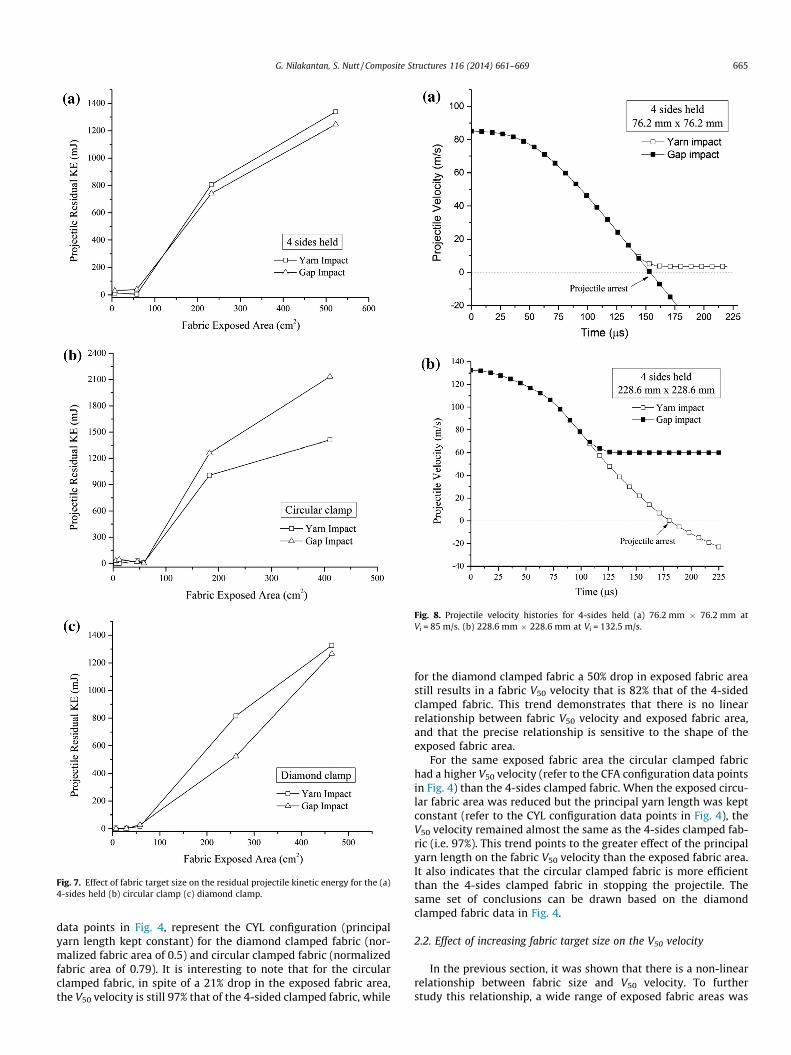
Fig. 7. Effect of fabric target size on the residual projectile kinetic energy for the (a)4-sides held (b) circular clamp (c) diamond clamp.
Fig. 8. Projectile velocity histories for 4-sides held (a) 76.2 mm � 76.2 mm atVi = 85 m/s. (b) 228.6 mm � 228.6 mm at Vi = 132.5 m/s.
G. Nilakantan, S. Nutt / Composite Structures 116 (2014) 661–669 665
data points in Fig. 4, represent the CYL configuration (principalyarn length kept constant) for the diamond clamped fabric (nor-malized fabric area of 0.5) and circular clamped fabric (normalizedfabric area of 0.79). It is interesting to note that for the circularclamped fabric, in spite of a 21% drop in the exposed fabric area,the V50 velocity is still 97% that of the 4-sided clamped fabric, while
for the diamond clamped fabric a 50% drop in exposed fabric areastill results in a fabric V50 velocity that is 82% that of the 4-sidedclamped fabric. This trend demonstrates that there is no linearrelationship between fabric V50 velocity and exposed fabric area,and that the precise relationship is sensitive to the shape of theexposed fabric area.
For the same exposed fabric area the circular clamped fabrichad a higher V50 velocity (refer to the CFA configuration data pointsin Fig. 4) than the 4-sides clamped fabric. When the exposed circu-lar fabric area was reduced but the principal yarn length was keptconstant (refer to the CYL configuration data points in Fig. 4), theV50 velocity remained almost the same as the 4-sides clamped fab-ric (i.e. 97%). This trend points to the greater effect of the principalyarn length on the fabric V50 velocity than the exposed fabric area.It also indicates that the circular clamped fabric is more efficientthan the 4-sides clamped fabric in stopping the projectile. Thesame set of conclusions can be drawn based on the diamondclamped fabric data in Fig. 4.
2.2. Effect of increasing fabric target size on the V50 velocity
In the previous section, it was shown that there is a non-linearrelationship between fabric size and V50 velocity. To furtherstudy this relationship, a wide range of exposed fabric areas was
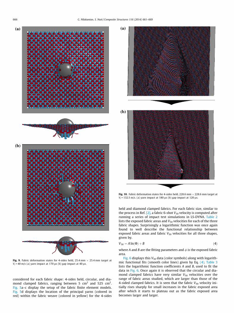
Fig. 9. Fabric deformation states for 4-sides held, 25.4 mm � 25.4 mm target atVi = 40 m/s (a) yarn impact at 170 ls (b) gap impact at 40 ls.
Fig. 10. Fabric deformation states for 4-sides held, 228.6 mm � 228.6 mm target atVi = 132.5 m/s. (a) yarn impact at 180 ls (b) gap impact at 120 ls.
666 G. Nilakantan, S. Nutt / Composite Structures 116 (2014) 661–669
considered for each fabric shape: 4-sides held, circular, and dia-mond clamped fabrics, ranging between 5 cm2 and 525 cm2.Fig. 5a–c display the setup of the fabric finite element models.Fig. 5d displays the location of the principal yarns (colored inred) within the fabric weave (colored in yellow) for the 4-sides
held and diamond clamped fabrics. For each fabric size, similar tothe process in Ref. [2], a fabric 6-shot V50 velocity is computed afterrunning a series of impact test simulations in LS-DYNA. Table 2lists the exposed fabric areas and V50 velocities for each of the threefabric shapes. Surprisingly a logarithmic function was once againfound to well describe the functional relationship betweenexposed fabric areas and fabric V50 velocities for all three shapes,given by.
V50 ¼ A lnðUÞ þ B ð4Þ
where A and B are the fitting parameters and / is the exposed fabricarea.
Fig. 6 displays this V50 data (color symbols) along with logarith-mic functional fits (smooth color lines) given by Eq. (4). Table 3lists the logarithmic function coefficients A and B, used to fit thedata in Fig. 6. Once again it is observed that the circular and dia-mond clamped fabrics have very similar V50 velocities over therange of fabric areas studied, which are larger than those of the4-sided clamped fabrics. It is seen that the fabric V50 velocity ini-tially rises sharply for small increases in the fabric exposed areaafter which it starts to plateau out as the fabric exposed areabecomes larger and larger.
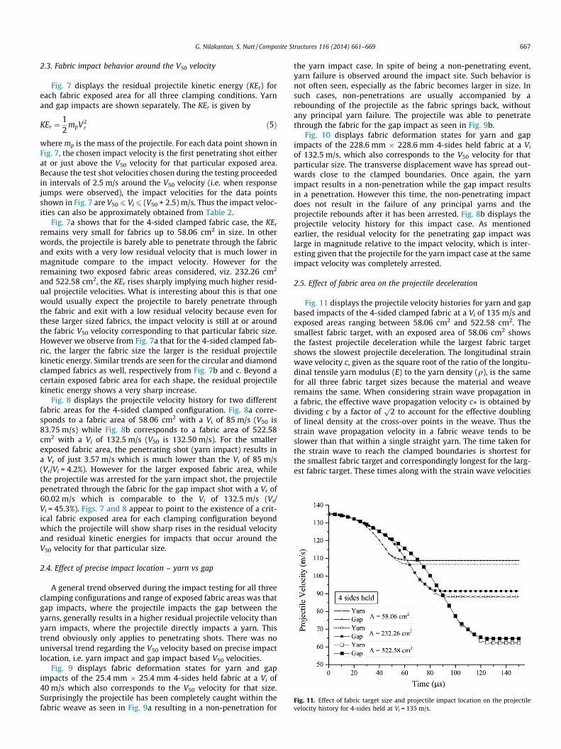
Fig. 11. Effect of fabric target size and projectile impact location on the projectilevelocity history for 4-sides held at Vi = 135 m/s.
G. Nilakantan, S. Nutt / Composite Structures 116 (2014) 661–669 667
2.3. Fabric impact behavior around the V50 velocity
Fig. 7 displays the residual projectile kinetic energy (KEr) foreach fabric exposed area for all three clamping conditions. Yarnand gap impacts are shown separately. The KEr is given by
KEr ¼12
mpV2r ð5Þ
where mp is the mass of the projectile. For each data point shown inFig. 7, the chosen impact velocity is the first penetrating shot eitherat or just above the V50 velocity for that particular exposed area.Because the test shot velocities chosen during the testing proceededin intervals of 2.5 m/s around the V50 velocity (i.e. when responsejumps were observed), the impact velocities for the data pointsshown in Fig. 7 are V50 6 Vi6 (V50 + 2.5) m/s. Thus the impact veloc-ities can also be approximately obtained from Table 2.
Fig. 7a shows that for the 4-sided clamped fabric case, the KEr
remains very small for fabrics up to 58.06 cm2 in size. In otherwords, the projectile is barely able to penetrate through the fabricand exits with a very low residual velocity that is much lower inmagnitude compare to the impact velocity. However for theremaining two exposed fabric areas considered, viz. 232.26 cm2
and 522.58 cm2, the KEr rises sharply implying much higher resid-ual projectile velocities. What is interesting about this is that onewould usually expect the projectile to barely penetrate throughthe fabric and exit with a low residual velocity because even forthese larger sized fabrics, the impact velocity is still at or aroundthe fabric V50 velocity corresponding to that particular fabric size.However we observe from Fig. 7a that for the 4-sided clamped fab-ric, the larger the fabric size the larger is the residual projectilekinetic energy. Similar trends are seen for the circular and diamondclamped fabrics as well, respectively from Fig. 7b and c. Beyond acertain exposed fabric area for each shape, the residual projectilekinetic energy shows a very sharp increase.
Fig. 8 displays the projectile velocity history for two differentfabric areas for the 4-sided clamped configuration. Fig. 8a corre-sponds to a fabric area of 58.06 cm2 with a Vi of 85 m/s (V50 is83.75 m/s) while Fig. 8b corresponds to a fabric area of 522.58cm2 with a Vi of 132.5 m/s (V50 is 132.50 m/s). For the smallerexposed fabric area, the penetrating shot (yarn impact) results ina Vr of just 3.57 m/s which is much lower than the Vi of 85 m/s(Vr/Vi = 4.2%). However for the larger exposed fabric area, whilethe projectile was arrested for the yarn impact shot, the projectilepenetrated through the fabric for the gap impact shot with a Vr of60.02 m/s which is comparable to the Vi of 132.5 m/s (Vr/Vi = 45.3%). Figs. 7 and 8 appear to point to the existence of a crit-ical fabric exposed area for each clamping configuration beyondwhich the projectile will show sharp rises in the residual velocityand residual kinetic energies for impacts that occur around theV50 velocity for that particular size.
2.4. Effect of precise impact location – yarn vs gap
A general trend observed during the impact testing for all threeclamping configurations and range of exposed fabric areas was thatgap impacts, where the projectile impacts the gap between theyarns, generally results in a higher residual projectile velocity thanyarn impacts, where the projectile directly impacts a yarn. Thistrend obviously only applies to penetrating shots. There was nouniversal trend regarding the V50 velocity based on precise impactlocation, i.e. yarn impact and gap impact based V50 velocities.
Fig. 9 displays fabric deformation states for yarn and gapimpacts of the 25.4 mm � 25.4 mm 4-sides held fabric at a Vi of40 m/s which also corresponds to the V50 velocity for that size.Surprisingly the projectile has been completely caught within thefabric weave as seen in Fig. 9a resulting in a non-penetration for
the yarn impact case. In spite of being a non-penetrating event,yarn failure is observed around the impact site. Such behavior isnot often seen, especially as the fabric becomes larger in size. Insuch cases, non-penetrations are usually accompanied by arebounding of the projectile as the fabric springs back, withoutany principal yarn failure. The projectile was able to penetratethrough the fabric for the gap impact as seen in Fig. 9b.
Fig. 10 displays fabric deformation states for yarn and gapimpacts of the 228.6 mm � 228.6 mm 4-sides held fabric at a Vi
of 132.5 m/s, which also corresponds to the V50 velocity for thatparticular size. The transverse displacement wave has spread out-wards close to the clamped boundaries. Once again, the yarnimpact results in a non-penetration while the gap impact resultsin a penetration. However this time, the non-penetrating impactdoes not result in the failure of any principal yarns and theprojectile rebounds after it has been arrested. Fig. 8b displays theprojectile velocity history for this impact case. As mentionedearlier, the residual velocity for the penetrating gap impact waslarge in magnitude relative to the impact velocity, which is inter-esting given that the projectile for the yarn impact case at the sameimpact velocity was completely arrested.
2.5. Effect of fabric area on the projectile deceleration
Fig. 11 displays the projectile velocity histories for yarn and gapbased impacts of the 4-sided clamped fabric at a Vi of 135 m/s andexposed areas ranging between 58.06 cm2 and 522.58 cm2. Thesmallest fabric target, with an exposed area of 58.06 cm2 showsthe fastest projectile deceleration while the largest fabric targetshows the slowest projectile deceleration. The longitudinal strainwave velocity c, given as the square root of the ratio of the longitu-dinal tensile yarn modulus (E) to the yarn density (q), is the samefor all three fabric target sizes because the material and weaveremains the same. When considering strain wave propagation ina fabric, the effective wave propagation velocity c⁄ is obtained bydividing c by a factor of
p2 to account for the effective doubling
of lineal density at the cross-over points in the weave. Thus thestrain wave propagation velocity in a fabric weave tends to beslower than that within a single straight yarn. The time taken forthe strain wave to reach the clamped boundaries is shortest forthe smallest fabric target and correspondingly longest for the larg-est fabric target. These times along with the strain wave velocities
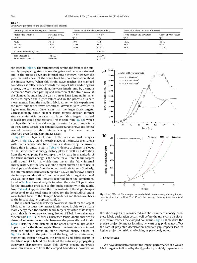
Table 4Strain wave propagation and characteristic time instants.
Geometry and Wave Propagation Distance Time to reach the clamped boundary Simulation Time Instants of Interest
Fabric edge length a Distance d = a/2 t = d/c t⁄ = d/c⁄ Slope change and deviation Onset of yarn failure(mm) (mm) (ls) (ls) (ls) (ls)
76.20 38.10 5.03 7.11 15.50 45.50152.40 76.20 10.05 14.21 26.30 69.50228.60 114.30 15.08 21.32 38.30 100.40
Strain wave velocity (m/s) Formula
Yarn (actual), c 7581.03p
(E/q)Fabric (effective), c⁄ 5360.60
p(E/2q)
Fig. 12. (a) Effect of fabric target size on the fabric internal energy history for yarnimpacts of 4-sides held at Vi = 135 m/s (b) close-up showing time instants ofinterest.
668 G. Nilakantan, S. Nutt / Composite Structures 116 (2014) 661–669
are listed in Table 4. The yarn material behind the front of the out-wardly propagating strain wave elongates and becomes stressedand in the process develops internal strain energy. However theyarn material ahead of the wave front has no information aboutthe impact event. When this strain wave reaches the clampedboundaries, it reflects back towards the impact site and during thisprocess, the yarn stresses along the yarn length jump by a certainincrement. With each passing and reflection of the strain wave atthe clamped boundaries, the yarn stresses keep jumping in incre-ments to higher and higher values and in the process dissipatemore energy. Thus the smallest fabric target, which experiencesthe most number of wave reflections, develops yarn stresses tohigher magnitudes at faster rates than the larger fabric targets.Correspondingly these smaller fabric targets develop internalstrain energies at faster rates than larger fabric targets that leadto faster projectile decelerations. This is seen from Fig. 12a whichdisplays the fabric internal energy histories for yarn impacts inall three fabric targets. The smallest fabric target shows the fastestrate of increase in fabric internal energy. The same trend isobserved even for the gap impact cases.
Fig. 12b displays a close-up of the fabric internal energiesshown in Fig. 12a around the early stages of the impact event alongwith three characteristic time instants as denoted by the arrows.These time instants, listed in Table 4, denote a change in slopesof the fabric internal energy history plots as well as a deviationfrom the other plots. For example, the increase in magnitude ofthe fabric internal energy is the same for all three fabric targetsuntil around 15.5 ls at which time instant the fabric internalenergy history for the smallest fabric target shows a sharp rise inthe slope and deviates from the other two fabric targets. Similarly,the intermediate sized fabric target (A = 232.26 cm2) shows a sharprise in slope and deviation from the largest fabric target at around26.3 ls. Note that time instants reported from the simulations,listed in Table 4, have already factored out the extra 2.3 ls it takesfor the impacting projectile to first make contact with the fabric.From Table 4, it appears that the time instants of the slope changescorrespond to the total time it takes for the longitudinal strainwave to first travel to the clamped boundaries and then travel backto the impact site, i.e. approximately 2t⁄.
The residual projectile velocity however is lowest for the largestfabric target because the largest fabric target is able to dissipatemore energy than the smaller fabric targets by virtue of its longeryarns, that leads to increased magnitudes of fabric internal energyas seen from Fig. 12a, as well as increased fabric kinetic energies byvirtue of momentum transfer between the projectile and fabric.Table 4 lists the time instants of the onset of yarn failure at theimpact site for the three targets. These time instants are obtainedfrom the sudden drops in fabric internal energy shown inFig. 12a. Similar to the principal of the longitudinal strain wave,momentum transfer between the projectile and fabric occurs inthe fabric region behind the fronts of the outwardly propagatingtransverse displacement wave. This slower moving transversewave can also reflect from the clamped boundaries, however for
the fabric target sizes considered and chosen impact velocity, com-plete fabric perforation occurs well before the transverse displace-ment wave reaches the clamped boundaries. Fig. 11 shows that theprecise projectile impact location, i.e. yarn or gap, does not affectthe rate of projectile deceleration however gap impacts lead tohigher projectile residual velocities, as previously noted.
3. Conclusions
We have demonstrated that the impact performance of a wovenfabric target as indicated by the V50 velocity is highly dependent on
G. Nilakantan, S. Nutt / Composite Structures 116 (2014) 661–669 669
the size of the fabric target for fully clamped fabrics. The V50 veloc-ity showed an initial sharp rise in magnitude with increasingexposed fabric areas that eventually showed a plateauing effect.The circular and diamond shaped clamped fabrics showed nearlyidentical V50 velocities over the range of fabric target sizes studied,which were both higher than the 4-sided clamped fabric.
A logarithmic function fit to the simulation data (penetratingshots) was shown to provide almost identical V50 velocity esti-mates as a 6-shot V50 velocity. The relationship between theexposed fabric area and V50 velocity was also found to be logarith-mic over the range of studied target sizes.
For all three clamping configurations, there appeared to be acritical fabric size beyond which the residual projectile kineticenergy showed a very sharp rise in magnitude when the fabricwas impacted at a velocity around its corresponding V50 velocity.It was observed that smaller sized fabric targets led to faster pro-jectile decelerations but higher residual velocities than larger sizedfabrics, attributed to the reduced time it takes the longitudinalstrain wave to reach the clamped boundaries and the correspond-ing faster rate of increase in the fabric internal strain energy.
The knowledge of the effect of fabric clamping design and fabricsize is useful when assessing and comparing the impact perfor-mances of different ballistic fabric materials and weaves, especiallyacross different laboratories. Through this and a previous study [2],we have shown these factors to be important determinants ofimpact performance.
Acknowledgements
Computation for the work described in this paper was sup-ported by the University of Southern California Center for High-Performance Computing and Communications (hpcc.usc.edu). GNand SN acknowledge support from the M.C. Gill Composites Center.
References
[1] Tabiei A, Nilakantan G. Ballistic impact of dry woven fabric composites: Areview. Appl Mech Rev 2008;61:010801–13.
[2] Nilakantan G, Nutt S. Effects of clamping design on the ballistic impact responseof soft body armor. Composite Struct 2014;108:137–50.
[3] J Singletary, T Steinruck, P Fitzgerald, Effects of boundary conditions on V50 andzone of mixed results of fabric armor targets, 23rd International Symposium onBallistics, Tarragona, Spain. (April 16–20, 2007).
[4] Zhang GM, Batra RC, Zheng J. Effect of frame size, frame type, and clampingpressure on the ballistic performance of soft body armor. Composites: Part B2008;39:476–89.
[5] G Nilakantan, ED Wetzel, R Merrill, TA Bogetti, R Adkinson, M Keefe, et al.Experimental and numerical testing of the V50 impact response of flexiblefabrics: Addressing the effects of fabric boundary slippage, 11th InternationalLS-DYNA Users Conference, Dearborn, MI, USA. (June 6–8, 2010).
[6] G Nilakantan. DYNAFAB User Manual Version 1.0, Nilakantan Composites. ISBN978-81-910696-0-0. (May 2010).
[7] Livermore Software Technology Corporation. LS-DYNA Keyword User’s ManualVersion 971, (May 2007).
[8] JP Lambert, GH Jonas. Towards standardization in terminal ballistics testing:Velocity representation, BRL Report No. 1852, U.S. Army Ballistic ResearchLaboratories, Aberdeen Proving Ground, MD. (1976).