Embed Size (px)
Citation preview
I I I I I I I I I I I I I I I I I I I
A COMPAcr RADAR ALTIMETER SATELUTE FOR MONITORING GLOBAL CUMATE CHANGE
J. A Giannini, C. C. Kilgus and E. 1... Reynolds The Johns Hopkins University/Applied Physics Laboratory
Laurel, Maryland
Abstract
Altimetry has become the focus of global climate studies because it is the only tool available able to provide both mesoscale (100-500 kIn) and basin-scale (10,000 kIn) circulation information on a global, synoptic basis. . The Atlas-launched Navy Geosat mission proved the capability of the radar altimeter to measure the mesoscale ocean features. A lightsat compatible Geosat Follow-On Technology Model (GTM) altimeter, capable of Scout or Pegasus launch and with half the weight and power (63-lbs and 69-W) of the Geosat altimeter, was developed and built at JHU/AP1... This altimeter demonstrated the feasibility of a compact satellite version of Geosat. The Navy is now procuring a series of compact altimeter satellites to support their tactical operations and to provide mesoscale data for global climate change monitoring. With the successful performance evaluation of GTM, APL now is pursuing the next step in exploring a compact altimeter mission to meet the needs of basin-scale global climate monitoring. A conceptual design, showing that the stringent centimeter precision measurement capability requirement can be met, includes a C-band channel for correcting for ionospheric effects. This improvement in performance will provide a basin-scale measurement capability in a compact satellite design that is a fraction of the weight and power of the Arianelaunched· TOPEX mission.
I. Introduction
Ocean Circulation and Global Climate Change
There is mounting concern over the anticipated effects of global climate change resulting from both man-made and natural events. The Earth provides man-kind a thin blanket of air, a thinner film of water, and the thinnest veneer of soil to support the daily needs of more than five
billion people. Catastrophic changes have been made to the local environment; e.g., in the ecosysterns of our rivers, bays and near-shore oceans, that now are taken for granted. Concern is increasing that the Earth's global environment also may be changing in ways to which we may not easily adjust.
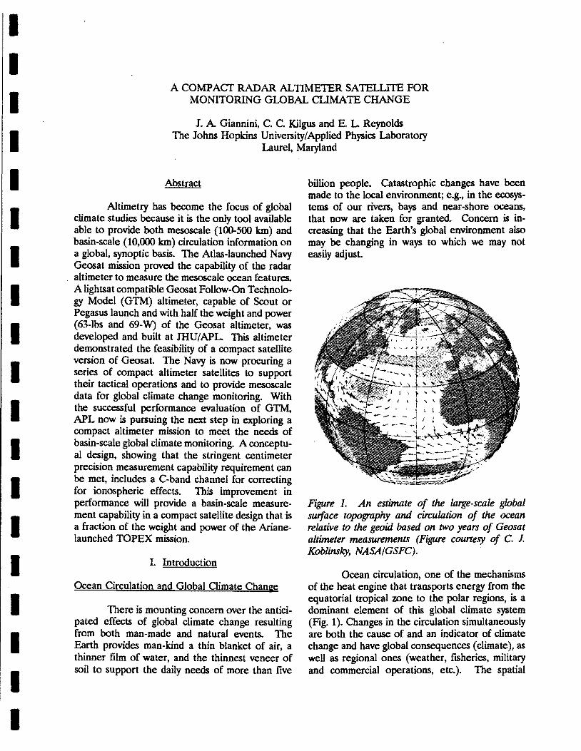
Figure 1. An estimate of the large-scale global surface topography and circulation of the ocean relative to the geoid based on two years of Geosat altimeter measurements (Figure courtesy of C. 1. Koblinsky, NASA/GSFC).
Ocean circulation, one of the mechanisms of the heat engine that transports energy from the equatorial tropical zone to the polar regions, is a dominant element of this global climate system (Fig. 1). Changes in the circulation simultaneously are both the cause of and an indicator of climate change and have global consequences (climate), as well as regional ones (weather, fISheries, military and commercial operations, etc.). The spatial
scales of interest for the circulation, therefore, range from mesoscale (on the order of 100 kIn) to basin-scale (on the order of 10,000 kIn). Temporal scales of interest range from the yearly variations in the time-averaged, large-scale mean circulation to monthly (or even weekly) variations in the energetic, small-scale time-dependent processes that are superimposed on the mean field
The fundamental altimetric concept for measuring ocean circulation is simple. Movement of the water in the ocean, for spatial scales exceeding about 30 kIn and temporal scales exceeding about 1 day, is affected strongly by the Coriolis force due to the Earth's rotation. These effects are manifested by deflections in the sea surface, that is, by changes in the mean sea level associated with the strength and direction of the flow. This change in topography varies from a I-meter increase in mean sea level in 100 kIn across the Gulf Stream to a lO-cm change in over 1000 kIn during an El Nino event in the tropical Pacific.
Given the strength of the sea surface topography signature, one can infer the magnitude and direction of the ocean water movement. The sea surface elevation changes measured by the altimeter reflect more than just surface conditions.
Hydrodynamics shows that a sea surface topography change over 500 kIn reflects oceanic currents to depths of 500 to 1000 meters.
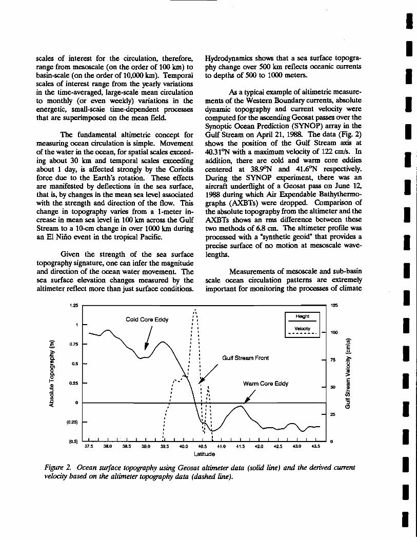
h a typical example of altimetric measurements of the Western Boundary currents, absolute dynamic topography and current velocity were computed for the ascending Geosat passes over the Synoptic Ocean Prediction (SYNOP) array in the Gulf Stream on April 21, 1988. The data (Fig. 2) shows the position of the Gulf Stream axis at 40.31 ~ with a maximum velocity of 122 cm/s. In addition, there are cold and warm core eddies centered at 38.ffi and 41.6~ respectively. During the SYNOP experiment, there was an aircraft underflight of a Geosat pass on June 12, 1988 during which Air Expendable Bathythermographs (AXBTs) were dropped. Comparison of the absolute topography from the altimeter and the AXBTs shows an rms difference between these two methods of 6.8 cm. The altimeter profIle was processed with a "synthetic geoid" that provides a precise surface of no motion at mesoscale wavelengths.
Measurements of mesoscale and sub-basin scale ocean circulation patterns are extremely important for monitoring the processes of climate
1.25 r-----------------------------....., 125
g >-.s::. a. !!! C) 0 a. 0 I-
CD :; "0 II) .c c(
Cold Core Eddy
0.75
0.5
0.25
• • 0
, , , ,
• (0.25) • ,
. " · , • • • • · , • •
• • • • • Gulf Stream Front
~ ~ 100
50
25
(0.5) 0 37.5 38.0 38.5 39.0 39.5 40.0 40.5 41.0 41.5 42.0 42.5 43.0 43.5
latitude
Figure 2. Ocean surface topography using Geosat altimeter data (solid line) and the derived current velocity based on the altimeter topography data (dashed line).
I I I I I I I I I I I I I I I I I I I
I I I I I I I I I I I I I I I I I I I
change. For example, understanding the annual phytoplankton bloom in the North Atlantic is a crucial aspect of the Earth's biogeochemical cycle and important aspects· of its investigation and dynamics are dependent on mesoscale circulation patterns such as those found in the Gulf Stream. Also, ocean dynamics affects the partial pressure of CO2 and its direct absorption in the ocean; and, mesoscale circulation significantly impacts this important aspect of the global carbon cycle.
Although dramatic results have been achieved, past altimetric missions were not designed for the purpose of understanding the contribution of long-wavelength altimetry to global change. The absolute mesoscale wavelength topography agreement shown.for Geosat is possible only because the energy in the orbit determination, propagation correction and synthetic geoid errors are predominantly at long wavelengths. Measurements of basin-scale mean circulation were corrupted by system inaccuracies. Circulation measurements needed for monitoring climate change will require that the basin-scale errors be reduced to the few centimeter level. TOPEX deals with these long-wavelength errors by employing a dualfrequency altimeter to correct for range delays due to the ionosphere, a radiometer to measure path column water vapor content, and, a GPS receiver and laser tracking system to provide precise orbits.
The Radar Altimeter
The altimeter functions as a nadir-looking, high-resolution pulse-compression radar that measures the distance from the satellite to the ocean surface with accuracies on the order of a few centimeters. This range measurement, combined with precise knowledge of the satellite orbit, propagation effects, and the Earth's geopotential field, provides a measure of the sea height above the geoid (surface of no motion) along a line under the satellite.
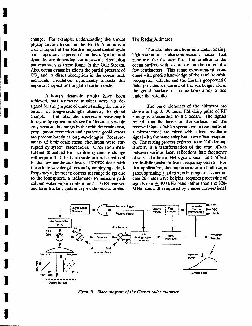
The basic elements of the altimeter are shown in Fig. 3. A linear PM chirp pulse of RF energy is transmitted to the ocean. The signals reflect from the facets on the surface; and, the received signals (which spread over a few tenths of a microsecond) are mixed with a local oscillator signal with the same chirp but at an offset frequency. The mixing process, referred to as "full deramp . stretch", is a transformation of the time offsets between various facet reflections into frequency offsets. (In linear PM signals, small time offsets are indistinguishable from frequency offsets. For this application, the implementation of 60 range gates, spanning + 14 meters in range to accommodate 20 meter wave heights, requires processing of signals in a + 300-kHz band rather than the 320-MHz bandwidth required by a more conventional
.... /7=.. TIlIIlSmIt trtgger
~~--~ "-1--- ~trtgger
~~~l Coarse Height
AdaptiVe ..... Tracker
(mlcrocomp.)
SWH
AGe Height
~ -., [;~-'a- 1.._~_Dual_d_~_Ital.....J ~ 1st 2nd ~ Local oscillator
ii2,ll ~; 102.4 sec ~
Ocean Swface
DIgital FIlter Bank
Figure 3. Block diagram of the Geosat radar altimeter.
1------'---..... WaV8form Samples
Sample index
approach.) The deramped signal is first converted to baseband in-phase and quadrature bipolar video, then analog/digital converted and finally spectrally analyzed, using fast Fourier transform techniques, to produce the waveform samples that are processed by the adaptive tracker.
In a closed height-tracking loop, the adaptive tracker acts on the waveform samples to center the fast-rising leading edge of the ocean return within the bank of fllters, or range gates. The timing required to adjust to the two-way path delay (to and from the ocean surface) is set in two parts: (a) a coarse delay that positions the local oscillator pulse in 12.5-nanosecond steps, and, (b) a fine frequency offset that positions the center of the overall fllter bank in steps that are equivalent to 0.05 nanoseconds (0.7 cm) over a + 6.25-nanosecond range. It would be extremely difficult to achieve this level of resolution using only time domain processing.
The adaptive tracker also forms estimates of the leading edge slope (providing significant wave height) and signal strength (providing wind speed).
Altimeter Range Corrections
The altimeter measurement is subject to various errors which require corrections to the raw waveform sample in order to achieve the accuracy necessary for basin-scale or mesoscale circulation measurements.
Orbit Uncertainty
An altimetric satellite measures the distance above the ocean surface; and, the usefulness of the measurement depends on the accuracy with which the center of mass of the satellite can be located with respect to the geocentric coordinate system, the radial component of the position being the most important. For studies of circulation, the accuracy must be better than the ocean surface signature to be determined.
For mesoscale measurements, it was demonstrated that less precise orbits (+ 50 cm rms) were sufficient provided the long wavelength
error is removed. The orbit errors are mainly on the scale of the Earth's circumference and this confinement to long wavelengths is the basis for many orbit error removal schemes, such as, removing a quadratic fit from the data Such schemes have little impact on the mesoscale signals; but, they remove a significant part of the large-scale signal Thus for basin-scale measurements, precision orbits (+ 5-cm accuracy for wavelengths of 10,000 km) are required.
Ionospheric Correction
Increasing the free electrons in the ionosphere also decreases the velocity of radar pulses; and, this causes the altimeter to overestimate its height. The effect varies linearly with the number of electrons and inversely with frequency. Typically the electron content varies by an order of magnitude from day to night, from summer to winter, and from solar minimum to maximum in the sunspot cycle.
The ionospheric range correction requires a measurement of the Total Electron Content (TEC) integrated along the altimeter subsatellite line of sight For past mesoscale missions, this correction was computed from an empirical model fitted to nonsimultaneous ground-based observations, and, accurate to about 50% of the ionospheric range delay (from 2 to 20 cm). Basin-scale measurements, however, require a direct measurement of the range delay that is accurate to at least 90% (better than 2 cm). One approach (to be used by TOPEX) derives the range correction by measuring the range to the surface at different frequencies.
At 13.5 GHz, the ionosphere causes path delays that can lengthen the apparent distance from the satellite to the surface from 5 to 25 em potentially masking oceanographic circulation signatures. To mitigate this effect, TOPEX will employ altimeters transmitting at two separate frequencies (Ku-band, 13.6 GHz and C-band, 5.3 GHz) simultaneously. A concomitant and important advantage is that TOPEX will provide the best measurement yet of the spatial variability of the ionosphere.
I I I I I I I I I I I I I I I I I I I
I I I I I I I I I I I I I I I I I I I
The first order ionospheric correction is computed by assuming that the measured heights from the Ku-band and C-band altimeters are given by
where the subscripts refer to the frequency band and ho is the actual height. The I is the total electron content in the atmosphere and the A is a constant 40.3 m3J(electrons-s2). Solving the pair of equations to eliminate A and I gives
the combined height estimate, corrected for the ionosphere.
The potential exists to make basin-scale measurements with the single-frequency GFO altimeter by making use of the onboard GPS receiver. Combining the GPS to GFO range delay information with the GPS to ground data provides total electron content information concurrent with the altimeter measurement which can be used to dynamically drive ionospheric models and thus determine the nadir-looking altimeter correction.
Tropospheric Correction
As in the ionosphere, radar pulse propagation velocities through the troposphere (wet and dry) are decreased causing the altimeter to overestimate its height. Although the dry tropospheric error is the larger of the two (on the order of 2 meters), it has less of an impact on mesoscale measurements because it is predominantly long wavelength; while, the wet tropospheric error contains more short wavelength energy.
The range delay caused by the tropospheric dry gases is proportional to the sea level pressure.
Because of the long-wavelength nature of the error, correction for mesoscale mission data can be achieved in much the same way as for the longwavelength orbit errors. To correct to 1-cm accuracy for a basin-scale mission, however, sea level pressure must be known with an accuracy of 4 mb. The accuracy of these models for making the correction is to be determined by TOPEX.
The water vapor content in the atmosphere has high variability in both spatial and temporal scales. Energetic events associated with weather fronts have temporal scales of hours to days and spatial scales of tens to hundreds of kilometers. Diurnal fluctuations have been found to cause radar range delays in excess of 3 cm rms. Anomalously high fluctuations are associated with weather fronts but the percentage of time this occurs is small and thus has only a very small impact on mesoscale measurements.
For the> mesoscale mission of Geosat, the applied correction was based on the model of Fleet Numerical Oceanographic Center (FNOC) which had an accuracy on the order of 6 cm rms (and lacked much of the highest scale variability) as determined by the Gulf of Alaska Seasat Experiment. However, correction for these variations, for basin-scale missions, require the use of a nadirlooking microwave radiometer to measure, coincidentally, the total water column content. That same experiment showed corrections based on radiometer data can be made to accuracies on the order of better than 2 cm.
II. Geosat Follow-On Mesoscale Mission
The Navy Geosat Mission
The Navy Geosat mission was a 1450-1b, Atlas-launched radar altimeter satellite launched in 1985; and, for the next five years it satisfied the mesoscale mission for both the Navy and the oceanographic community. During its operation, the data set allowed the Navy to map fronts and eddies in support of submarine operations, enabled NOAA to map the tropical Pacific Ocean (including the generation and propagation of the 1986 EI Nino), and advanced the state of knowledge of ocean circulation.
The Geosat altimeter was a 165-W, 207-lb, Ku-band (13.5 GHz) radar that measured the sea surface topography with a precision of 3.5 cm. The altimeter, with its I-meter antenna, was a linear descendent of the NASA Seasat altimeter launched in 1978 (5-cm precision) and the Geos-3 altimeter launched in 1975 (2O-cm precision). Geosat used a 20-W traveling wave tube amplifier, space qualified and in production for the Landsat program. A gallium arsenide field-effect transistor (GaAsFE1) provided a 5-dB front-end noise figure. The transmitted waveform had a time-bandwidth product of 32,768 (l02.4-"s pulse width x 320-MHz chirp bandwidth) where the initial bandwidth of 40 MHz was generated in the digital chirp generator and subsequently multiplied by 8 to achieve the desired 320-MHz band. An adaptive tracker controlled the altimeter through various calibrate, track, standby and test modes in response to commands received via the spacecraft command link, and, formatted the height, automatic gain control (AGC), waveheight, status and engineering data for output to the spacecraft telemetry system.
The Geosat mission was intended to provide detailed, high-density, and timely monitoring of mesoscale oceanography. To this end, the exact repeat mission provided monitoring on a 120-km grid every 17 days. The large long-wavelength components of orbital, ionospheric, water vapor, geoidal, and other errors were eliminated by removing a tilt and bias (or quadratic) from the data over a 1000- or 2000-km span. The mesoscale mission requirements for the altimeter are summarized in Table 1.
The Navy Geosat Follow-On (GFO) Mission
Seeking a cost effective way to maintain
altimeter monitoring of the ocean, the Navy has sponsored the development of a low-power, lightweight, redundant instrument with Geosat performance that is compatible with a radar altimeter lightsaL As part of this effort, JHU/APL developed a conceptual design (Fig. 4) for a system that satisfied the Geosat mission requirements in Table 1 (including the same 800-km orbit with the 120-km grid spacing) and that was consistent with a small launch vehicle. This design included an altimeter, a radiometer (for direct measurement of the total atmospheric water column content) and a GPS receiver for precision tracking1
•
In a nose-up, DMSP-like configuration, the altimeter dish (36-inch diameter) is mounted on the earth-facing side of the spacecraft. The nadirlooking radiometer offset parabolic (24-inch diameter) is fixed to the forward end of the spacecrafL The radiometer does not deploy, it fits in the "boattail" of the dynamic envelope in the launch configuration. The payload electronics are mounted on the altimeter alignment deck (under the altimeter dish) inside the spacecraft box structure.
A form, fit and function engineering model altimeter, the Geosat Follow-on Technology Model (GTM) altimeter, has beCn built to that conceptual design at JHU/APL This 69-W, 63-lb altimeter (half the weight and power of the Geosat altimeter) demonstrated the feasibility of a compact satellite version of Geosat by successfully performing to the specifications consistent with Geosat. Through the Geosat Follow-On (GFO) Program, the Navy is now procuring from its winning contractor an operational series of compact altimeter satellites that will provided ocean data to support their operational needs.
Table 1 Geosat Altimeter Mission Requirements
Mean altitude Height measurement Significant wave height (SWH) Wind speed
800km <3.5 cm for 2-m SWH 10% of SWH or 0.5 m, whichever is greater 1.8 m/s over a range of 1-18 m/s
I I I I I I I I I I I I I I I I I I I
I I I I I I I I I I I I I I I I I I I
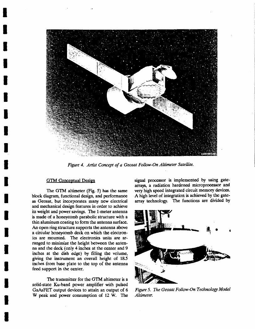
Figure 4. Artist Concept of a Geosat Follow-On Altimeter Satellite.
GTM Conceptual Design
The GTM altimeter (Fig. 5) has the same block diagram, functional design, and performance as Geosat, but incorporates many new electrical and mechanical design features in order to achieve its weight and power savings. The I-meter antenna is made of a honeycomb parabolic structure with a thin aluminum coating to form the antenna surface. An open ring structure supports the antenna above a circular honeycomb deck on which the electronics are mounted. The electronics units are arranged to minimize the height between the antenna and the deck (only 4 inches at the center and 9 inches at the dish edge) by filling the volume, giving the instrument an overall height of 18.5 inches from base plate to the top of the antenna feed support in the center.
The transmitter for the GTM altimeter is a solid-state Ku-band power amplifier with pulsed GaAsFET output devices to attain an output of 6 W peak and power consumption of 12 W. The
signal processor is implemented by using gatearrays, a radiation hardened microprocessor and very high speed integrated circuit memory devices. A high level of integration is achieved by the gatearray technology. The functions are divided by
_ ...• -..-.... ~ .
Figure 5. The Geosat Follow-On Technology Model Altimeter.
logic speed: the fast timing critical portions of the function are in an electron-coupled-Iogic gatearray, and the slower portions are in a complementary metal oxide semiconductor gate-array. In addition, the digital filter bank uses a digital signal processor not previously available. These improvements have resulted in a signal processor packaged on only two multi-layer printed circuit boards that require only 12 W, less that half the power required by Geosat.
Radiometer Conceptual Desi~n
The GFO Technology Model radiometer concept consists of two channels placed on either side of the water vapor line. Each channel measures the brightness temperature in a path column identical to that traversed by the altimeter pulses. A 21-GHz channel brightness temperature is heavily influenced by the amount of water vapor in the column because of pressure broadening of the water vapor line centered at 22.232 GHz while a 37-GHz channel serves as a "dry" reference. Calibration of the two channels is done by periodically switching from the altimeter path column to a sky hom (cold load) and to a base load (hot load) in order to establish a temperature scale for the input to the processor.
The processor controls the calibration switching, digitizes the analog outputs from the two channels and calculates the brightness temperature. An algorithm is used to estimate the integrated column water vapor density from the observed brightness temperature and a second algorithm is used to estimate the path delay experienced by the altimeter pulses.
The calibration switches (between the antenna and the calibration path, and, between the sky hom and the base load in the calibration path) and the Dicke switch (between the antenna and the reference load) must have low insertion loss to preserve the system noise temperature but must also be highly repeatable and stable in insertion loss to preserve calibration.
Following the Dicke switch, a heterodyne system is employed in order to keep the predetection bandwidth to a few hundred MHz which
outputs to a square law detector. A broader bandwidth, while increasing the detectable temperature sensitivity would reduce the sensitivity to the pressure broadening effect of water vapor density on the width of a line. It is this effect which is used by the algorithm to estimate the water vapor density from the observed brightness temperature. A double sideband mixer is employed, since both sidebands are useful and thus there is no need to reject one. There is an isolator ahead of the mixer to prevent gain and noise temperature modulation of the mixer by variations in the source impedance of the two states of the Dicke switch.
Following a square law detection, the Dicke switch state is change in a synchronous or phase sensitive detector. Low pass filtering then processes a slowly varying analog signal whose amplitude is proportional to the difference between the antenna (or calibration) temperature and the reference load. This output is passed to the processor for digitization and brightness temperature computation. The I-kHz Dicke switching signal and the calibration switch commands are generated in the processor.
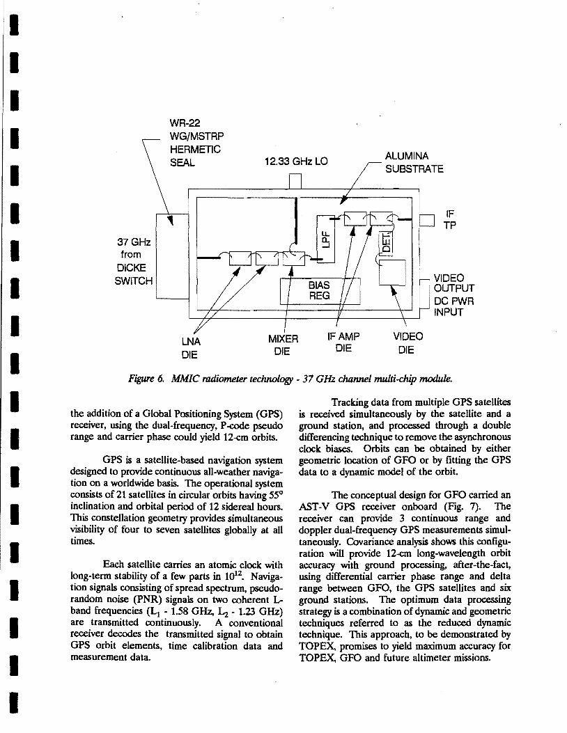
The active RF and analog portions of the radiometer channel are fabricated with MMIC and analog array IC technology in order to achieve a dramatic reduction in size and weight (Fig. 6). The microwave switches are realize with waveguide latching ferrite circulators. The isolator function is achieved with a source insensitive MMIC low noise amplifier (LNA). The low noise Schottky mixer and the 10 to 110 MHz IF amplifier are MMICs. The video amplifier, synchronous detector, low pass filter and analog buffer amplifiers are fabricated on a silicon analog array chip. The unpackaged IC chips are bonded to each other and to an alumina substrate which is housed in a hermetically sealed flat box. Hermetically sealed waveguide to alumina micros trip transitions connect the Dicke switch and the local oscillator (LO).
Global Positioning System (GPS) Receiver
Using Doppler orbits, Geosat was able to achieve radial orbit accuracy of 4 meters. With an improved gravity model, Doppler orbits of 1 to 2 meters can be achieved by GFO. However, with
I I I I I I I I I I I I I I I I I I I
I I I I I I I I I I I I I I I I I I I
WR-22 WG/MSTRP HERMETIC SEAL 12.33 GHz La ALUMINA
SUBSTRATE
37GHz from
DICKE SWITCH
LNA DIE
MIXER DIE DIE
IF TP
. VIDEO
. OUTPUT DCPWR INPUT
Figure 6. MMIC radiometer technology - 37 GHz channel multi-chip module.
the addition of a Global Positioning System (GPS) receiver, using the dual-frequency, P-code pseudo range and carrier phase could yield 12-cm orbits.
GPS is a satellite-based navigation system designed to provide continuous all-weather navigation on a worldwide basis. The operational system consists of 21 satellites in circular orbits having 550
inclination and orbital period of 12 sidereal hours. This constellation geometry provides simultaneous visibility of four to seven satellites globally at all times.
Each satellite carries an atomic clock with long-term stability of a few parts in 1012• Navigation signals consisting of spread spectrum, pseudorandom noise (PNR) signals on two coherent Lband frequencies (Lt - 1.58 GHz, L.z - 1.23 GHz) are transmitted continuously. A conventional receiver decodes the transmitted signal to obtain GPS orbit elements, time calibration data and measurement data.
Tracking data from multiple GPS satellites is received simultaneously by the satellite and a ground station, and processed through a double differencing technique to remove the asynchronous clock biases. Orbits can be obtained by either geometric location of GFO or by fitting the GPS data to a dynamic model of the orbit.
The conceptual design for GFO carried an AST-V GPS receiver onboard (Fig. 7). The receiver can provide 3 continuous range and doppler dual-frequency GPS measurements simultaneously. Covariance analysis shows this configuration will provide 12-cm long-wavelength orbit accuracy with ground processing, after-the-fact, using differential carrier phase range and delta range between GFO, the GPS satellites and six ground stations. The optimum data processing strategy is a combination of dynamic and geometric techniques referred to as the reduced dynamic technique. This approach, to be demonstrated by TOPEX, promises to yield maximum accuracy for TOPEX, GPO and future altimeter missions.
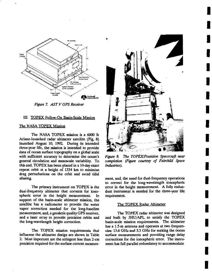
Figure 7. AST V GPS Receiver
III. TOPEX Follow-On Basin-Scale Mission
The NASA TOPEX Mission
The NASA TOPEX mission is a 6000 lb Ariane·launched radar altimeter satellite (Fig. 8) launched August 10, 1992. During its intended three-year life, the mission is intended to provide data of ocean surface topography on a global scale with sufficient accuracy to determine the ocean's general circulation and mesoscale variability. To this end, TOPEX has been placed in a 1O-dayexact repeat orbit at a height of 1334 km to minimize drag perturbations on the orbit and avoid tidal aliasing.
The primary instrument on TOPEX is the dual-frequency altimeter that corrects for ionospheric error in the height measurement. In support of the basin-scale altimeter mission, the satellite has a radiometer to provide the water vapor correction needed for the long-baseline measurement, and, a geodetic quality GPS receiver, and a laser array to provide precision orbits and the long-wavelength height correction.
The TOPEX mission requirements that influence the altimeter design are shown in Table 2. Most important are the stringent less than 2-cm precision required for the surface current measure-
,.
Figure 8. The TOPEX/Poseidon Spacecraft near completion (Figure courtesy of Fairchild Space Industries).
ment, and, the need for dual-frequency operations to correct for the long-wavelength ionospheric error in the height measurement. A fully redundant instrument is needed for the three-year life requirement.
The TOPEX Radar Altimeter
The TOPEX radar altimeter was designed and built by JHU/APL to satisfy the TOPEX basin-scale mission requirements. The altimeter has a l.5-m antenna and operates at two frequencies: 13.6 GHz and 5.3 GHz for making the ocean surface measurements and providing range delay corrections for the ionospheric error. The instrument has full parallel redundancy to accommodate
I I' I I I I I I I I I I I I I I I I I

I I I I I I I I I I I I I I I I I I I
Table 2 TOPEX Mission Requirements and Constraints
Mean altitude 1334 km + 60 km Height measurement Significant wave height (SWH)
<2 cm per 10 days drift error 10% of SWH or 0.5 m, whichever is greater, over a
Wind speed Surface currents
range of 1 to 20 m +2 mls '
Ionospheric total electron content (TEC) Time tag error
+ 1 cmls (accuracy) over a 250-km grid at mid-latitude 4xlO16 e/m2 100 j,Ls to universal time coordinated, including space
Attitude range Ocean surface conditions
craft induced error 00 to 0.4~ off-nadir 6-20 dBm2 (Ku-band) 4-20 dBm2 (C-band)
the three-year lifetime. It has a high pulse repetition frequency which takes full advantage of available pulse-to-pulse independence at high wave heights, thus delivering improved height noise measurements over that of Geosat; and, there is dual-resolution acquisition and tracking implementation to meet the S-s acquisition requirement and improve recovery in the event of track loss. The design includes a gated C-band solid-state amplifier and gate-array based high-speed synchronizer and chirp-generator.
The altimeter is packaged in an F-shaped configuration, with the 1.5-m dish attached to one side (Fig. 9). A burst waveform accommodates the dual frequency transmission and reception with 38 Ku-band pulses and 10 C-band pulses in constant relative timing within the bursts and variable interburst intervals to accommodate the range measurement.
A TOPEX Follow-On (!Fa) Conceptual Desim
With the successful performance evaluation of the GTM altimeter, JHU/APL is now pursuing the next step in exploring a compact mission to meet the needs of global monitoring that is compatible with small launch vehicles (e.g. Pegasus, Taurus, Scout II). This includes developing a
conceptual design for a compact follow-on payload (altimeter, radiometer, GPS receiver) with full TOPEX measurement capability as given in Table 2 (including the same 1334 km, 10-day exact repeat orbit). The altimeter design begins with a single frequency GTM-like altimeter and adds an independent second C-band channel to provide the dual-frequency capability.
Figure 9. The dual frequency, redundant TOPEX altimeter.
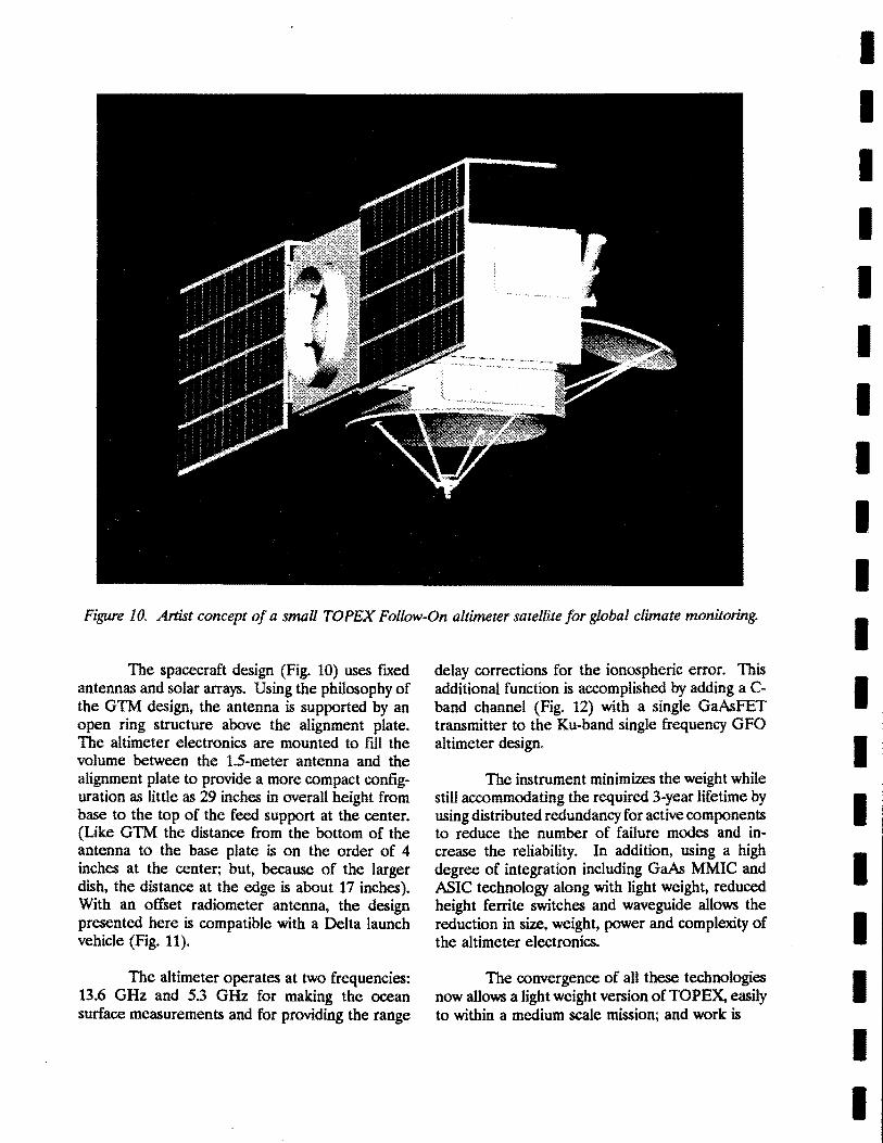
Figure 10. Artist concept of a small TOPEX Follow-On altimeter satellite for global climate monitoring.
The spacecraft design (Fig. to) uses fIXed antennas and solar arrays. Using the philosophy of the GlM design, the antenna is supported by an open ring structure above the alignment plate. The altimeter electronics are mounted to fill the volume between the 1.5-meter antenna and the alignment plate to provide a more compact configuration as little as 29 inches in overall height from base to the top of the feed support at the center. (Like GlM the distance from the bottom of the antenna to the base plate is on the order of 4 inches at the center; but, because of the larger dish, the distance at the edge is about 17 inches). With an offset radiometer antenna, the design presented here is compatible with a Delta launch vehicle (Fig. 11).
The altimeter operates at two frequencies: 13.6 GHz and 5.3 GHz for making the ocean surface measurements and for providing the range
delay corrections for the ionospheric error. This additional function is accomplished by adding a Cband channel (Fig. 12) with a single GahFET transmitter to the Ku-band single frequency GFO altimeter design.
The instrument minimizes the weight while still accommodating the required 3-year lifetime by using distributed redundancy for active components to reduce the number of failure modes and increase the reliability. In addition, using a high degree of integration including Gah MMIC and ASIC technology along with light weight, reduced height ferrite switches and waveguide allows the reduction in size, weight, power and complexity of the altimeter electronics.
The convergence of all these technologies now allows a light weight version of TOPEX, easily to within a medium scale mission; and work is
II
I I I I I I I I I I I I I I I I I I

I I I I I I I I .1 I I I I I I I I I I
SPACECRAFT STRUCTURE
SOLAR ARRAYS (STOWED)
PAYLOAD ADAPTER
DELTA FAIRING ENVELOPE
STAR CAMERA
SPACECRAFT STRUCTURE
DELTA FAIRING ENVELOPE
ALTIMETER ---...,....- ELECTRONICS
1.5 METER ALTiMETER
DELTAS.5' FAIRING
ALTiMETER ELECTRONICS
1.5 METER ALTiMETER
Figure 11. Launch configuration on a Delta launch vehicle.
Antenna -.:::----~7 1.5m dish
Dual
Digital Chirp
Generator
Receive Trigger
AnaIo9'dlgital ..... --------1 Converters
Waveform samples
, Adaptive Tracker
HeightSWHAGC
Figure 12. Block diagram for a dual-frequency TOPEX Follow-On altimeter.
proceeding with the design to reduce further the weight, ~ize, and power to provide compatibility with small (Pegasus, Taurus, or Scout II) launch vehicles.
References
Ie. c. Kilgus, E. J. Hoffman and W. E. Frain, "Monitoring the Ocean with Radar Altimeter Lightsats," Proc. of 3rd Annual AIAA/USU Conf. on Small Satellites, Sept. 1989.