Embed Size (px)
Citation preview

Binary OutputSeries 9175
ww
w.s
tah
l.d
e
A3
A3
A3
A3
A3
A3
Series 9175 A32014-06-03·AK00·III·en
09822E00
A3
A3
A3
A3
A3
A3
A3
A3
NEC 500Class I Class II Class III
Division 1 2 1 2 1 2Ex iinterface
x x x x x x
Installation in x x x
WebCode 9175A
Iso
> Intrinsically safe output[Ex ia] IIC / [Ex ib] IIC
> Galvanic isolation betweeninput, output and power supply
> Open-circuit and short-circuit monitoring (can be switched off)
> For use up to SIL 3 (IEC 61508)
Binary outputs are used for intrinsically safe operation of Ex i solenoid valves, indicator lamps or horns. Binary output is available in single or double channel versions.
ATEX / IECEx NEC 505 NEC 506Class I
Zone 0 1 2 20 21 22 Zone 0 1 2 20 21 22Ex i interface
x x x x x x Ex iinterface
x x x
Installation in x x Installation in x x
lators A3/1

Binary OutputSeries 9175
A3/2
Selection TableVersion Channels No-load voltage
UoutMax. output current Iout max
Internal resistance Ri
Order number
Binary output Series 9175
1 10 V 60 mA 150 Ω 9175/10-12-11s17.5 V 45 mA 130 Ω 9175/10-14-11s25 V 35 mA 250 Ω 9175/10-16-11s
2 10 V 60 mA / 120 mA *) 150 Ω / 75 Ω *) 9175/20-12-11s17.5 V 45 mA / 90 mA *) 130 Ω / 65 Ω *) 9175/20-14-11s25 V 35 mA / 70 mA *) 250 Ω / 125 Ω *) 9175/20-16-11s
*) Parallel connection of the outputs possible; thus, doubling of the output current.Note The order numbers listed in the table are for devices equipped with screw-type terminals.
For devices equipped with spring-type terminals, replace the ending "s" for screw-type terminals with "k" for spring-type terminals.
Explosion ProtectionGlobal (IECEx)
Gas and dust IECEx BVS 10.0050XEx nA nC [ia Ga] IIC T4 Gc[Ex ia Da] IIIC
Europe (ATEX)Gas and dust DMT 03 ATEX E 043 X
E II 3 (1) G Ex nA nC [ia Ga] IIC T4 GcE II (1) D [Ex ia Da] IIIC
Certifications and certificatesCertificates IECEx, ATEX, Brazil (INMETRO), India (PESO), Canada (cFM), Kazakhstan (GOST K),
Russia (GOST R), Ukraine (TR), USA (FM, UL), Belarus (operating authorisation) Ship approval DNV
Functional safety (IEC 61508)Test report STAHL 07/10-01 R012Max. SIL 3Safe Failure Fraction SFF
PFDAVG at T[Proof]
Further information see test reportFurther parameters
Installation in Zone 2, Div. 2 and in the safe areaFurther information see respective certificate and operating instructions
single output parallel output94 % 93 %
PFDAVG
T(Proof) single output parallel output1 year 4,25 x 10⁻⁵ 8,36 x 10⁻⁵
2 years 8,12 x 10⁻⁵ 1,60 x 10⁻⁴
5 years 1,97 x 10⁻⁴ 3,89 x 10⁻⁴
Isolators 2014-06-03·AK00·III·en

Binary Output for Imax = 60 mASeries 9175/.0-12-11
A3
A3
A3
A3
A3
A3
A3
A3
A3
A3
A3
A3
A3
Series 9175/.0-12-11
Technical DataSafety data
Max. values per outputVersion 9175/10-12-11. (1 channel) 9175/20-12-11. ( 2 channels)Max. voltage Uo 11.3 V 11.3 V Max. current Io
[Ex ia] 75 mA 75 mA [Ex ib] – – – –
The binary outputs 9175 can also be used for supply of devices marked EEx ib IIC/IIB T*. Here the Io values for [Ex ib] are valid.
Max. power Po 210 mW 210 mW Max. connectable capacitance
IIC 1.79 μF 1.79 μFIIB 12.1 μF 12.1 μF
Max. connectable inductanceIIC 6.3 mH 6.3 mHIIB 25 mH 25 mH
Internal capacitance Ci 1.1 nF 1.1 nFInternal inductance Li negligible negligibleIsolation voltage Um 253 V AC 253 V AC
Maximum values for two outputs connected in parallel
Version 9175/10-12-11. (1 channel) 9175/20-12-11. ( 2 channels)Max. voltage Uo – – 11.3 VMax. current Io
[Ex ia] – – 150 mA [Ex ib] – – – –
The binary outputs 9175 can also be used for supply of devices marked EEx ib IIC/IIB T*. Here the Io values for [Ex ib] are valid.
Max. power Po – – 420 mW Max. connectable capacitance
IIC – – 1.79 μFIIB – – 12.1 μF
Max. connectable inductanceIIC – – 1.5 mHIIB – – 6 mH
Internal capacitance Ci – – 2.2 nFinternal inductance Li – – negligibleIsolation voltage Um – – 253 V AC
Ex i outputOutput characteristic
Maximum values per output Version 9175/10-12-11. (1 channel) 9175/20-12-11. ( 2 channels)No-load voltage Uout 10 V 10 VMax. output current Iout max 60 mA 60 mAInternal resistance Ri 150 Ω 150 ΩResidual ripple output ( 50 mV ( 50 mV Switching delay AUS ↔ EIN ( 1 ms ( 1 ms Switching frequency ( 200 Hz ( 200 Hz Display LED yellow "OUT" each channel LED yellow "OUT" each channel
(at UN; - 20 ... + 60 °C)
09882E00
X-axis (I [mA])A: characteristic curve each channelB: characteristic curve channel 1 parallel
channel 2 (only types 9175/20-..-...)
Isolators A3/32014-06-03·AK00·III·en
A3

Binary Output for Imax = 60 mASeries 9175/.0-12-11
A3/4
Ex i outputMaximum values for two outputs connected in parallel
Version 9175/10-12-11. (1 channel) 9175/20-12-11. ( 2 channels)No-load voltage Uout – – 10 VMax. output current Iout max – – 120 mAInternal resistance Ri – – 75 ΩResidual ripple output – – ( 50 mV Switching delay AUS ↔ EIN – – ( 1 ms Switching frequency – – ( 200 Hz Display – – LED yellow "OUT" each channel
Fault detection Ex i outputVersion 9175/10-12-11. (1 channel) 9175/20-12-11. ( 2 channels)Open-circuit
per output > 7 kΩ > 7 kΩtwo outputs parallel – – > 3,5 kΩ
Short circuitper output, at 23 °C 40...60 Ω ± 3 Ω / 10 K 40...60 Ω ± 3 Ω / 10 Ktwo outputs parallel, at 23 °C
– – 20...30 Ω ± 3 Ω / 10 K
Test currentper output
100 Ω load 2,7 mA 2,7 mA7 kΩ load 0,68 mA 0,68 mA
two outputs parallel100 Ω load – – 5,4 mA7 kΩ load – – 1,36 mA
Settings (Switch LF) activated / deactivated activated / deactivatedError detection LED red "LF" each channel LED red "LF" each channelSignalization of faulty line and power supply failure
- Contact (30 V / 100 mA) closed to ground in case of fault- pac-Bus, floating contact (30 V / 100 mA)
Technical Data
Isolators 2014-06-03·AK00·III·en

Binary Output for Imax = 45 mASeries 9175/.0-14-11
A3
A3
A3
A3
A3
A3
A3
A3
A3
A3
A3
A3
A3
Series 9175/.0-14-11
Technical DataSafety data
Max. values per outputVersion 9175/10-14-11. (1 channel) 9175/20-14-11. ( 2 channels)Max. voltage Uo 19.6 V 19.6 V Max. current Io
[Ex ia] 150 mA 150 mA [Ex ib] 60 mA 60 mA
The binary outputs 9175 can also be used for supply of devices marked EEx ib IIC/IIB T*. Here the Io values for [Ex ib] are valid.
Max. power Po 732 mW 732 mW Max. connectable capacitance
IIC 235 nF 235 nFIIB 1470 nF 1470 nF
Max. connectable inductanceIIC 1.5 mH 1.5 mHIIB 6 mH 6 mH
Internal capacitance Ci 1.1 nF 1.1 nFInternal inductance Li negligible negligibleIsolation voltage Um 253 V AC 253 V AC
Maximum values for two outputs connected in parallel
Version 9175/10-14-11. (1 channel) 9175/20-14-11. ( 2 channels)Max. voltage Uo – – 19.6 VMax. current Io
[Ex ia] – – 300 mA [Ex ib] – – 120 mA
The binary outputs 9175 can also be used for supply of devices marked EEx ib IIC/IIB T*. Here the Io values for [Ex ib] are valid.
Max. power Po – – 1464 mW Max. connectable capacitance
IIC – – 235 nFIIB – – 1471 nF
Max. connectable inductanceIIC – – 0.3 mHIIB – – 1.5 mH
Internal capacitance Ci – – 2.2 nFinternal inductance Li – – negligibleIsolation voltage Um – – 253 V AC
Ex i outputOutput characteristic
Maximum values per outputVersion 9175/10-14-11. (1 channel) 9175/20-14-11. ( 2 channels)No-load voltage Uout 17.5 V 17.5 VMax. output current Iout max 45 mA 45 mAInternal resistance Ri 130 Ω 130 ΩResidual ripple output ( 50 mV ( 50 mV Switching delay AUS ↔ EIN ( 1 ms ( 1 ms Switching frequency ( 200 Hz ( 200 Hz Display LED yellow "OUT" each channel LED yellow "OUT" each channel
(at UN; -20 ... +60 °C)
09883E00
X-axis (I [mA])A: characteristic curve each channelB: characteristic curve channel 1 parallel
channel 2 (only types 9175/20-..-...)
Isolators A3/52014-06-03·AK00·III·en
A3

Binary Output for Imax = 45 mASeries 9175/.0-14-11
A3/6
Ex i outputMaximum values for two outputs connected in parallel
Version 9175/10-14-11. (1 channel) 9175/20-14-11. ( 2 channels)No-load voltage Uout – – 17,5 VMax. output current Iout max – – 90 mAInternal resistance Ri – – 65 ΩResidual ripple output – – ( 50 mV Switching delay AUS ↔ EIN – – ( 1 ms Switching frequency – – ( 200 Hz Display – – LED yellow "OUT" each channel
Fault detection Ex i outputVersion 9175/10-14-11. (1 channel) 9175/20-14-11. ( 2 channels)Open-circuit
per output > 10 kΩ > 10 kΩtwo outputs parallel – – > 5 kΩ
Short circuitper output, at 23 °C 40...80 Ω ± 6 Ω / 10 K 40...80 Ω ± 6 Ω / 10 Ktwo outputs parallel, at 23 °C
– – 20...40 Ω ± 6 Ω / 10 K
Test currentper output
100 Ω load 2,1 mA 2,1 mA10 kΩ load 0,76 mA 0,76 mA
two outputs parallel100 Ω load – – 4,2 mA10 kΩ load – – 1,52 mA
Settings (Switch LF) activated / deactivated activated / deactivatedError detection LED red "LF" each channel LED red "LF" each channelSignalization of faulty line and power supply failure
- Contact (30 V / 100 mA) closed to ground in case of fault- pac-Bus, floating contact (30 V / 100 mA)
Technical Data
Isolators 2014-06-03·AK00·III·en

Binary Output for Imax = 35 mASeries 9175/.0-16-11
A3
A3
A3
A3
A3
A3
A3
A3
A3
A3
A3
A3
A3
Series 9175/.0-16-11
Technical DataSafety data
Max. values per outputVersion 9175/10-16-11. (1 channel) 9175/20-16-11. (2 channels)Max. voltage Uo 27.6 V 27.6 V Max. current Io
[Ex ia] 110 mA 110 mA [Ex ib] 50 mA 50 mA
The binary outputs 9175 can also be used for supply of devices marked EEx ib IIC/IIB T*. Here the Io values for [Ex ib] are valid.
Max. power Po 760 mW 760 mW Max. connectable capacitance
IIC 85 nF 85 nFIIB 667 nF 667 nF
Max. connectable inductanceIIC 1.2 mH 1.2 mHIIB 9 mH 9 mH
Internal capacitance Ci 1.1 nF 1.1 nFInternal inductance Li negligible negligibleIsolation voltage Um 253 V AC 253 V AC
Maximum values for two outputs connected in parallel
Version 9175/10-16-11. (1 channel) 9175/20-16-11. (2 channels)Max. voltage Uo – – 27.6 VMax. current Io
[Ex ia] – – 220 mA [Ex ib] – – 100 mA
The binary outputs 9175 can also be used for supply of devices marked EEx ib IIC/IIB T*. Here the Io values for [Ex ib] are valid.
Max. power Po – – 1520 mW Max. connectable capacitance
IIC – – - -IIB – – 665 nF
Max. connectable inductanceIIC – – - -IIB – – 1.8 mH
Internal capacitance Ci – – 2.2 nFinternal inductance Li – – negligibleIsolation voltage Um – – 253 V AC
Ex i outputOutput characteristic
Maximum values per outputVersion 9175/10-16-11. (1 channel) 9175/20-16-11. (2 channels)No-load voltage Uout 25 V 25 VMax. output current Iout max 35 mA 35 mAInternal resistance Ri 250 Ω 250 ΩResidual ripple output ( 50 mV ( 50 mV Switching delay AUS ↔ EIN ( 1 ms ( 1 ms Switching frequency ( 200 Hz ( 200 Hz Display LED yellow "OUT" each channel LED yellow "OUT" each channel
(at UN; -20 ... +60 °C)
09884E00
X-axis (I [mA])A: characteristic curve each channelB: characteristic curve channel 1 parallel
channel 2 (only types 9175/20-..-...)
Isolators A3/72014-06-03·AK00·III·en
A3

Binary Output for Imax = 35 mASeries 9175/.0-16-11
A3/8
Ex i outputMaximum values for two outputs connected in parallel
Version 9175/10-16-11. (1 channel) 9175/20-16-11. (2 channels)No-load voltage Uout – – 25 VMax. output current Iout max – – 70 mAInternal resistance Ri – – 125 ΩResidual ripple output – – ( 50 mV Switching delay AUS ↔ EIN – – ( 1 ms Switching frequency – – ( 200 Hz Display – – LED yellow "OUT" each channel
Fault detection Ex i outputVersion 9175/10-16-11. (1 channel) 9175/20-16-11. (2 channels)Open-circuit
per output > 15 kΩ > 15 kΩtwo outputs parallel – – > 7,5 kΩ
Short circuitper output, at 23 °C 50...90 Ω ± 8 Ω / 10 K 50...90 Ω ± 8 Ω / 10 Ktwo outputs parallel, at 23 °C
– – 25...45 Ω ± 8 Ω / 10 K
Test currentper output
100 Ω load 2,3 mA 2,3 mA15 kΩ load 0,72 mA 0,72 mA
two outputs parallel100 Ω load – – 4,6 mA15 kΩ load – – 1,44 mA
Settings (Switch LF) activated / deactivated activated / deactivatedError detection LED red "LF" each channel LED red "LF" each channelSignalization of faulty line and power supply failure
- Contact (30 V / 100 mA) closed to ground in case of fault- pac-Bus, floating contact (30 V / 100 mA)
Technical Data
Isolators 2014-06-03·AK00·III·en
Binary OutputSeries 9175
A3
A3
A3
A3
A3
A3
A3
A3
A3
A3
A3
A3
Series 9175
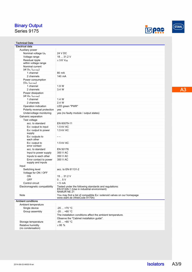
Technical DataElectrical data
Auxiliary powerNominal voltage UN 24 V DCVoltage range 18 ... 31.2 VResidual ripple within voltage range
( 3.6 VSS
Nominal current (at UN, Iout max)
1 channel 80 mA 2 channels 140 mA
Power consumption(UN, Iout max)
1 channel 1.9 W 2 channels 3.4 W
Power dissipation(at UN, Iout max)
1 channel 1.4 W 2 channels 2.4 W
Operation indication LED green "PWR"Polarity reversal protection yesUndervoltage monitoring yes (no faulty module / output states)
Galvanic separationTest voltage
acc. to standard EN 60079-11Ex i output to input 1.5 kV ACEx i output to power supply
1.5 kV AC
Ex i outputs to each other
– –
Ex i output to error contact
1.5 kV AC
acc. to standard EN 50178Input to power supply 350 V ACInputs to each other 350 V ACError contact to power supply and inputs
350 V AC
InputSwitching level acc. to EN 61131-2Voltage for ON / OFF
ON 15 ... 31.2 VOFF 0 ... 5 V
Control circuit < 5 mA Electromagnetic compatibility Tested under the following standards and regulations:
EN 61326-1 (Use in industrial environment)NAMUR NE 21
Note You may find a list of compatible Ex i solenoid valves on our homepagewww.stahl.de (WebCode 9175A)
Ambient conditionsAmbient temperature
Single device -20 ... +70 °CGroup assembly -20 ... +60 °C
The installation conditions affect the ambient temperature.Observe the "Cabinet installation guide".
Storage temperature -40 ... +80 °C Relative humidity(no condensation)
( 95 %
Isolators A3/92014-06-03·AK00·III·en
A3
A3

Binary OutputSeries 9175
A3/10
Electrical connectionConnection diagram
Mechanical dataConnection
Weight approx. 160 g Mounting type on top hat rail (NS35/15, NS35/7.5) or in pac-CarrierMounting orientation horizontal or verticalEnclosure IP30Terminals IP20Enclosure material PA 6.6Fire resistance (UL-94) V0
Technical Data
1 channel9175/10-1.-11.
06700E02
2 channel9175/20-1.-11.
06701E02
Field Device ISpac Isolator Control System
Division 1Zone 0 / 1
Division 2Zone 2
pac-Bus
active
Hazardous area Safe area
Field Device ISpac Isolator Control System
Division 1Zone 0 / 1
Division 2Zone 2
pac-Bus
active
Hazardous area Safe area
active
Screw-type terminals Spring-type terminalsSingle-wire connection- rigid- flexible- flexible with core end sleeves (without / with plastic sleeve)
0.2 ... 2.5 mm2
0.2 ... 2.5 mm2
0.25 ... 2.5 mm2
0.2 ... 2.5 mm2
0.2 ... 2.5 mm2
0.25 ... 2.5 mm2
Two-wire connection- rigid- flexible- flexible with core end sleeves
0.2 ... 1 mm2
0.2 ... 1.5 mm2
0.25 ... 1 mm2
- -- -0.5 ... 1 mm2
Isolators 2014-06-03·AK00·III·en
Binary OutputSeries 9175
A3
A3
A3
A3
A3
A3
A3
A3
A3
A3
A3
A3
A3
A3
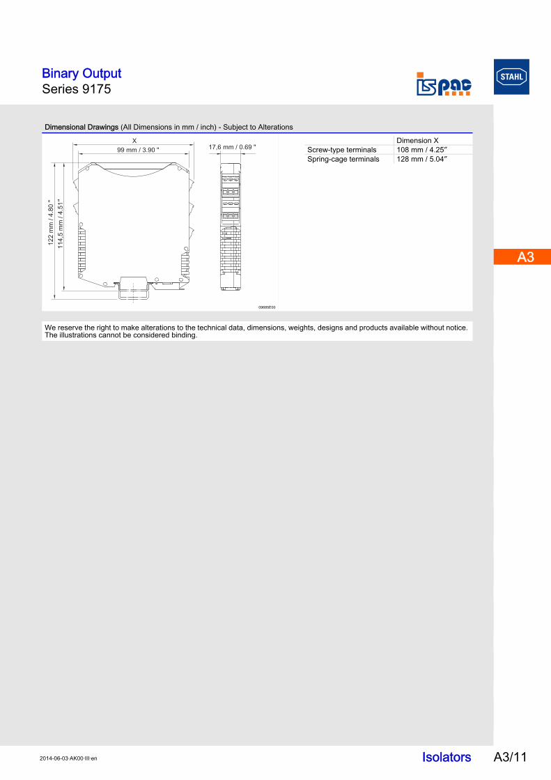
Dimensional Drawings (All Dimensions in mm / inch) - Subject to Alterations
09685E00
We reserve the right to make alterations to the technical data, dimensions, weights, designs and products available without notice. The illustrations cannot be considered binding.
X
122 m
m / 4
.80
"
114,5
mm
/ 4
.51
"
99 mm / 3.90 "17,6 mm / 0.69 "
Dimension XScrew-type terminals 108 mm / 4.25″Spring-cage terminals 128 mm / 5.04″
Isolators A3/112014-06-03·AK00·III·en