Embed Size (px)
DESCRIPTION
Runtime Library ManualMIL-STD-1553 Tester/Simulator
Citation preview
Runtime Library Manual
MIL-STD-1553 Tester/Simulator
MN-69068XX-001
The information provided in this Manual is believed to be accurate; however, no responsibility is assumed by Data Device Corporation for its use, and no license or
rights are granted by implication or otherwise in connection therewith.
Specifications are subject to change without notice.
Please visit our Web site at www.ddc-web.com for the latest information.
105 Wilbur Place, Bohemia, New York 11716-2426
For Technical Support - 1-800-DDC-5757 ext. 7771
Headquarters - Tel: (631) 567-5600, Fax: (631) 567-7358
United Kingdom - Tel: +44-(0)1635-811140, Fax: +44-(0)1635-32264
France - Tel: +33-(0)1-41-16-3424, Fax: +33-(0)1-41-16-3425
Germany - Tel: +49-(0)89-15 00 12-11, Fax: +49-(0)89-15 00 12-22
Japan - Tel: +81-(0)3-3814-7688, Fax: +81-(0)3-3814-7689
World Wide Web - http://www.ddc-web.com
Rev. K, October 2009 © 2001 Data Device Corp.
All rights reserved. No part of this Manual may be reproduced or transmitted in any form or by any means, electronic, mechanical, photocopying, recording, or otherwise, without the prior written
permission of Data Device Corporation.
Data Device Corporation BU-69068 Manual ii
RECORD OF CHANGE
Revision Date Pages Description
A 10/01 All Original Issue
B 3/02 x, 26, 71, 78, 163, 175
Corrections
C 12/02 1, 8, 9, 10, 11, 17, 18, 19, 21, 23, 24, 26, 30, 33, 36, 45, 74, 82, 86, 123, 159, 180, 181 200 Various
Replace BU-65558 part number with BU-65570M part number. IRIG Flag description corrected. BUS-69068 part number changed to BU-69068.
D 10/03 Various Added ddcGetGlueLogicVersion, ddcSetBcrtEventEx functions. Modified ddcInsertMessage, Table 11, Wait for Input Trigger routine. Misc typographical edits.
E 03/04 Various Added support documentation for LabVIEW, Visual Basic, and LabWindows. Added section on Compiling issues. Modified functions. Added additional RTL Error Messages. Modified RTL Error Messages.
F 1/05 163, 206, 216 Modified ddcSynchronizeAllCards, added SKIP_NEXT_MESSAGE_ONCE_EX TO Intermessage Routines.
G 12/06 97 Changed parameters in pos description.
H 12/07 218 Edited table reference
J 10/08 175 Removed the Monitor and RT sample2 section.
K 10/09 218 Edited description for Set Status Bit and Reset Status Bit. Added Appendix H.
Data Device Corporation BU-69068 Manual iii
TABLE OF CONTENTS
1 SOFTWARE LICENSE AND POLICIES ................................................................. IX
1.1.1 GRANT OF LICENSE ......................................................................................... ix
1.1.2 UPGRADES ........................................................................................................ ix
1.1.3 ADDITIONAL SOFTWARE/SERVICES ............................................................... x
1.1.4 TRANSFER ......................................................................................................... x
1.1.5 LIMITATION ON REVERSE ENGINEERING, DECOMPILATION, AND DISASSEMBLY ................................................................................................... x
1.1.6 TERMINATION .................................................................................................... x
1.1.7 EXPORT RESTRICTIONS ................................................................................... x
1.1.8 LIMITED WARRANTY FOR PRODUCT .............................................................. x
1.1.9 ANNUAL MAINTENANCE CONTRACT ............................................................... x
1.1.10 LIMITATION ON REMEDIES; NO CONSEQUENTIAL OR OTHER DAMAGES . xi
1.1.11 YOUR EXCLUSIVE REMEDY ............................................................................ xi
1.1.12 DISCLAIMER OF WARRANTIES ....................................................................... xi
1.1.13 EXCLUSION OF INCIDENTAL, CONSEQUENTIAL AND CERTAIN OTHER DAMAGES ......................................................................................................... xii
1.1.14 LIMITATION OF LIABILITY AND REMEDIES .................................................... xii
1.1.15 U.S. GOVERNMENT LICENSE RIGHTS ........................................................... xii
1.1.16 APPLICABLE LAW ............................................................................................ xii
1.1.17 ENTIRE AGREEMENT ...................................................................................... xii
2 PREFACE ................................................................................................................. 1
2.1 Text Usage ..................................................................................................................... 1
2.2 Trademarks .................................................................................................................... 1
2.3 Update Policy ................................................................................................................. 1
2.4 Technical Support .......................................................................................................... 1
3 OVERVIEW .............................................................................................................. 3
3.1 Supported Hardware ...................................................................................................... 3
4 SOFTWARE INSTALLATION .................................................................................. 4
4.1 Runtime Library – Windows® 9x/2000 & Windows NT® ................................................. 4
4.2 Runtime Library – DOS .................................................................................................. 9
4.2.1 DOS Version PCMCIA Requirements ................................................................. 9
4.2.2 Installing the RTL in DOS .................................................................................. 11
4.2.3 Setting Up the BU-65570M In DOS ................................................................... 11
4.3 Runtime Library – Linux® ............................................................................................. 13
4.4 Runtime Library – VxWorks® ....................................................................................... 13
4.5 DDC 1553 Card Manager For 95/98/2000 .................................................................... 14
4.6 DDC 1553 Card Manager For Windows NT .................................................................. 16
Data Device Corporation BU-69068 Manual iv
5 TESTER/SIMULATOR RTL ................................................................................... 21
5.1 Tester/Simulator RTL (Windows 9x/2000 & Windows NT) ............................................ 21
5.2 Tester/Simulator RTL (VxWorks, Windows/MXI-II) ....................................................... 21
5.2.1 Bus Controller Mode ......................................................................................... 21
5.2.2 Remote Terminal Mode..................................................................................... 21
5.2.3 Monitor Mode .................................................................................................... 22
5.2.4 Replay Mode ..................................................................................................... 22
6 HEADER FILES ..................................................................................................... 23
6.1 Type and Structure Definitions ..................................................................................... 23
6.2 Function Prototypes ...................................................................................................... 23
6.3 Initialization .................................................................................................................. 23
6.3.1 Initializing The DLL Functionality ....................................................................... 23
6.4 Multiple Card Functions ................................................................................................ 23
6.5 Generating PC Interrupts .............................................................................................. 24
6.6 Diagnostic Functions .................................................................................................... 24
7 CONFIGURING THE VXWORKS RTL ................................................................... 25
7.1 Setting Card Resources For Your System .................................................................... 25
7.2 Setting the Firmware Pathnames .................................................................................. 25
7.3 Interrupt Handling ......................................................................................................... 26
7.4 Monitor Interrupts ......................................................................................................... 26
7.5 Bus Controller and Remote Terminal Interrupts ............................................................ 27
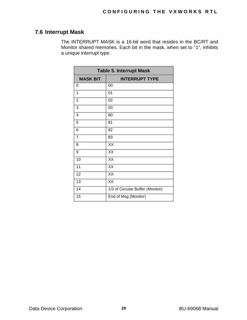
7.6 Interrupt Mask .............................................................................................................. 29
8 SAMPLE APPLICATION USING THE RTL ........................................................... 30
9 PROGRAMMER‟S REFERENCE ........................................................................... 37
10 FUNCTIONS BY HEADER ..................................................................................... 38
10.1 bc.h .............................................................................................................................. 38
10.2 err.h .............................................................................................................................. 39
10.3 int.h .............................................................................................................................. 40
10.4 irq.h .............................................................................................................................. 41
10.5 mt.h .............................................................................................................................. 42
10.6 rep.h ............................................................................................................................. 43
10.7 rt.h ................................................................................................................................ 44
10.8 vxworks.h ..................................................................................................................... 45
11 DLL HIGH-LEVEL FUNCTION DEFINITIONS ....................................................... 46
12 LABVIEW® INTRODUCTION .............................................................................. 175
12.1 System Requirements ................................................................................................ 175
12.2 Installation .................................................................................................................. 175
12.3 LabVIEW VI ................................................................................................................ 176
12.4 LabView Samples ....................................................................................................... 179
12.5 BC/MT Sample ........................................................................................................... 180
Data Device Corporation BU-69068 Manual v
12.6 RT Sample ................................................................................................................. 180
13 VISUAL BASIC INTRODUCTION ........................................................................ 181
13.1 System Requirements ................................................................................................ 181
13.2 Installation .................................................................................................................. 181
13.3 About Tester/Simulator Visual Basic Support ............................................................. 182
13.4 Visual Basic Samples ................................................................................................. 186
13.5 BC_RT_MT Sample ................................................................................................... 186
13.6 Monitor Sample .......................................................................................................... 186
13.7 RT Sample ................................................................................................................. 186
14 APPENDIX A ........................................................................................................ 187
14.1 RTL Error Messages .................................................................................................. 187
15 APPENDIX B ........................................................................................................ 208
15.1 Interrupts .................................................................................................................... 208
15.2 Monitor Interrupts ....................................................................................................... 208
15.3 Bus Controller and Remote Terminal Interrupts .......................................................... 209
15.4 Interrupt Mask ............................................................................................................ 211
16 APPENDIX C ........................................................................................................ 212
16.1 Intermessage Routines ............................................................................................... 212
17 APPENDIX D ........................................................................................................ 224
17.1 Communication Stack Structure ................................................................................. 224
18 APPENDIX E ........................................................................................................ 229
18.1 Structures ................................................................................................................... 229
18.1.1 CARD_STATE ................................................................................................ 229
18.1.2 ERR_ST ......................................................................................................... 229
18.1.3 COM_ST ......................................................................................................... 229
18.1.4 MON_MSG ..................................................................................................... 230
18.1.5 RT_DEFS ....................................................................................................... 230
18.1.6 RT_DEFS_NEW ............................................................................................. 230
19 APPENDIX F ........................................................................................................ 231
19.1 Compiler issues: Microsoft Visual C++ vs. Borland ..................................................... 231
19.1.1 BORLAND BUILDER: ..................................................................................... 231
19.1.2 BORLAND C++ SUITE 5.0x: .......................................................................... 232
20 APPENDIX G ........................................................................................................ 234
20.1 Using the LabWindows™/CVI Software ...................................................................... 234
20.1.1 Header Files ................................................................................................... 234
20.1.2 Running Projects............................................................................................. 234
20.2 Examples ................................................................................................................... 236
20.2.1 Version Sample .............................................................................................. 236
20.2.2 MT IRQ Sample .............................................................................................. 238
Data Device Corporation BU-69068 Manual vi
20.2.3 MT Threaded Sample ..................................................................................... 240
20.2.4 BC Sample...................................................................................................... 240
21 APPENDIX H ........................................................................................................ 242
21.1 Dual Processor and Dual Core Support ...................................................................... 242
22 INDEX ................................................................................................................... 244
Data Device Corporation BU-69068 Manual vii
LIST OF FIGURES Figure 1. RTL Install Welcome .................................................................................... 4 Figure 2. License Agreement ...................................................................................... 5
Figure 3. Install Directory ............................................................................................ 5 Figure 4. Select Components ...................................................................................... 6
Figure 5. Select LabVIEW Directory ........................................................................... 6
Figure 6. Select the Start Menu Group ....................................................................... 7 Figure 7. Installation Complete ................................................................................... 7
Figure 8. Install Done, Reboot .................................................................................... 8 Figure 9. PC Card Software Architecture .................................................................. 10
Figure 10. Control Panel ........................................................................................... 14
Figure 11. DDC 1553 Card Manager ........................................................................ 15 Figure 12. Card Manager Modify .............................................................................. 15
Figure 13. Control Panel .......................................................................................... 16 Figure 14. DDC 1553 Card Manager ........................................................................ 17
Figure 15. Device Driver Status ................................................................................ 17
Figure 16. Manage Non-PnP Devices ....................................................................... 18 Figure 17. Add New Device ...................................................................................... 18
Figure 18. Configuring the Card ................................................................................ 19 Figure 19. Modify Device .......................................................................................... 19
Figure 20. Control and Indicator Icons ................................................................... 179
Figure 21. LabWindows/CVI Add File Message Window ....................................... 235 Figure 22. LabWindows/CVI Project with Improperly Inserted Library File............. 235
Figure 23. LabWindows/CVI Project with Properly Inserted Library File ................ 236 Figure 24. Version Project Workspace ................................................................... 237
Figure 25. Version UIR .......................................................................................... 237
Figure 26. MT IRQ Project Workspace .................................................................. 238 Figure 27. MT IRQ UIR .......................................................................................... 239
Figure 28. BC Sample Project Workspace ............................................................. 241 Figure 29. BC Sample UIR..................................................................................... 241
Data Device Corporation BU-69068 Manual viii
LIST OF TABLES Table 1. Interrupt Vector ........................................................................................... 27 Table 2. RT Interrupt Types ...................................................................................... 27
Table 3. BC Interrupt Types ...................................................................................... 28 Table 4. BC Error Codes ........................................................................................... 28
Table 5. Interrupt Mask ............................................................................................. 29
Table 6. BC Error Definitions .................................................................................... 74 Table 7. RT Error Definitions ..................................................................................... 81
Table 8. BC.llb (Bus Controller Functions) .............................................................. 176 Table 9. Err.llb (Error Functions) ............................................................................. 176
Table 10. Int.llb (Interface Functions) ...................................................................... 177
Table 11. MT.llb (Monitor Functions) ...................................................................... 177 Table 12. Rep.llb (Replay Functions) ...................................................................... 178
Table 13. RT.llb (Remote Terminal Functions) ....................................................... 178 Table 14. BC.bas (Bus Controller Functions) .......................................................... 182
Table 15. Err.bas (Error Functions) ......................................................................... 183
Table 16. Int.bas (Interface Functions) ................................................................... 183 Table 17. Irq.bas (Interrupt Functions) .................................................................... 183
Table 18. MT.bas (Monitor Functions) .................................................................... 184 Table 19. Rep.bas (Replay Functions) .................................................................... 184
Table 20. RT.bas (Remote Terminal Functions) ..................................................... 185
Table 21. Interrupt Vector ....................................................................................... 209 Table 22. Rt Interrupt Types ................................................................................... 209
Table 23. BC Interrupt Types .................................................................................. 210 Table 24. BC Error Codes ....................................................................................... 210
Table 25. Interrupt Mask ......................................................................................... 211
Table 26. Intermessage Routines ........................................................................... 213 Table 27. Monitor Message Header ........................................................................ 224
Table 28. IRIG High Word Bit Definitions ................................................................ 226 Table 29. IRIG Low Word Bit Definitions ................................................................. 226
Table 30. Error Codes ............................................................................................. 227
Data Device Corporation BU-69068 Manual
ix
1 SOFTWARE LICENSE AND POLICIES
IMPORTANT—READ CAREFULLY: This Software License Agreement (―SLA‖) is a legal agreement between you (either an individual or a single entity) and Data Device Corporation (DDC) for this DDC software product, which includes computer software and may include associated media, printed materials, and ―online‖ or electronic documentation (―Product‖). YOU AGREE TO BE BOUND BY THE TERMS OF THIS SLA BY INSTALLING, COPYING, OR OTHERWISE USING THE PRODUCT. IF YOU DO NOT AGREE, DO NOT INSTALL OR USE THE PRODUCT; YOU MAY RETURN IT TO YOUR PLACE OF PURCHASE FOR A FULL REFUND.
1.1.1 GRANT OF LICENSE
DDC grants you the following rights provided that you comply with all terms and conditions of this SLA:
Installation and use. You may install, use, access, display and run one copy of the Product on a single computer, such as a workstation, terminal or other device (―Workstation Computer‖). The Product may not be used in conjunction with non-DDC devices. You may not use the Product to permit any Device to use, access, display or run other executable software residing on the Workstation Computer, nor may you permit any Device to use, access, display, or run the Product or Product‘s user interface, unless the Device has a separate license for the Product.
Storage/Network Use. You may also store or install a copy of the Product on a storage device, such as a network server, used only to install or run the Product on your other Workstation Computers over an internal network; however, you must acquire and dedicate an additional license for each separate Workstation Computer on or from which the Product is installed, used, accessed, displayed or run. A license for the Product may not be shared or used concurrently on different Workstation Computers.
Reservation of Rights. DDC reserves all rights not expressly granted to you in this SLA.
1.1.2 UPGRADES
To use a Product identified as an upgrade, you must first be licensed for the product identified by DDC as eligible for the upgrade. After upgrading, you may no longer use the product that formed the basis for your upgrade eligibility.
S O F T W A R E L I C E N S E A N D P O L I C I E S
Data Device Corporation BU-69068 Manual x
1.1.3 ADDITIONAL SOFTWARE/SERVICES
This SLA applies to updates of the Product that DDC may provide to you or make available to you after the date you obtain your initial copy of the Product, unless we provide other terms along with the update.
1.1.4 TRANSFER
You may move the Product to a different Workstation Computer. After the transfer, you must completely remove the Product from the former Workstation Computer. You may not rent, lease, lend or provide commercial services to third parties with the Product.
1.1.5 LIMITATION ON REVERSE ENGINEERING, DECOMPILATION, AND
DISASSEMBLY
You may not reverse engineer, decompile, or disassemble the Product.
1.1.6 TERMINATION
Without prejudice to any other rights, DDC may cancel this SLA if you do not abide by the terms and conditions of this SLA, in which case you must return all copies of the Product and all of its component parts.
1.1.7 EXPORT RESTRICTIONS
You acknowledge that the Product is of U.S. origin and subject to U.S. export jurisdiction. You agree to comply with all applicable international and national laws that apply to the Product, including the U.S. Export Administration Regulations, as well as end-user, end-use, and destination restrictions issued by U.S. and other governments.
1.1.8 LIMITED WARRANTY FOR PRODUCT
DDC warrants that the Product will perform substantially in accordance with the accompanying materials for a period of one (1) year from the date of receipt. Except for the warranty made above, DDC makes no warranty or representation of any kind, express or implied, with respect to the Products, including warranty as to their merchantability or fitness for a particular purpose or as to any other matter. All claims based upon defects shall be deemed waived unless made in writing and received by DDC within one (1) year after your receipt of the Product. New Product updates are available without charge during this one (1) year term of this warranty.
1.1.9 ANNUAL MAINTENANCE CONTRACT
After the expiration of the one (1) year limited warranty period, a Maintenance Contract may be purchased from DDC to extend the Product warranty period for an additional one (1) year from date of expiration. With the purchase of a valid Annual Maintenance Contract,
S O F T W A R E L I C E N S E A N D P O L I C I E S
Data Device Corporation BU-69068 Manual xi
the clauses defined in Section 8 shall remain intact. Maintenance Contracts can be renewed annually and must remain valid, without any lapses, to extend the Product warranty period.
1.1.10 LIMITATION ON REMEDIES; NO CONSEQUENTIAL OR OTHER
DAMAGES
Your exclusive remedy for any breach of this Limited Warranty is as set forth below. Except for any refund elected by DDC, YOU ARE NOT ENTITLED TO ANY DAMAGES, INCLUDING BUT NOT LIMITED TO CONSEQUENTIAL DAMAGES, if the Product does not meet DDC‘s Limited Warranty, and, to the maximum extent allowed by applicable law, even if any remedy fails of its essential purpose. The terms of Section 1.1.13 below (―Exclusion of Incidental, Consequential and Certain Other Damages‖) are also incorporated into this Limited Warranty. You may have others, which vary from state/jurisdiction to state/jurisdiction.
1.1.11 YOUR EXCLUSIVE REMEDY
DDC‘s and its suppliers‘ entire liability and your exclusive remedy shall be, at DDC‘s option from time to time exercised subject to applicable law, (a) return of the price paid (if any) for the Product, or (b) repair or replacement of the Product, that does not meet this Limited Warranty and that is returned to DDC. You will receive the remedy elected by DDC without charge, except that you are responsible for any expenses you may incur (e.g. cost of shipping the Product to DDC). This Limited Warranty is void if failure of the Product has resulted from accident, abuse, misapplication, abnormal use or a virus. Any replacement Product will be warranted for the remainder of the original warranty period or thirty (30) days, whichever is longer.
1.1.12 DISCLAIMER OF WARRANTIES
The Limited Warranty that appears above is the only express warranty made to you and is provided in lieu of any other express warranties (if any) created by any documentation, packaging, or other communications. Except for the Limited Warranty and to the maximum extent permitted by applicable law, DDC and its suppliers provide the Product and support services (if any) AS IS AND WITH ALL FAULTS, and hereby disclaim all other warranties and conditions, either express, implied or statutory, including, but not limited to, any (if any) implied warranties, duties or conditions of merchantability, of fitness for a particular purpose, of reliability or availability, of accuracy or completeness of responses, of results, of workmanlike effort, of lack of viruses, and of lack of negligence, all with regard to the Product, and the provision of or failure to provide support or other services, information, software, and related content through the Product or otherwise arising out of the use of the Product.
S O F T W A R E L I C E N S E A N D P O L I C I E S
Data Device Corporation BU-69068 Manual xii
1.1.13 EXCLUSION OF INCIDENTAL, CONSEQUENTIAL AND CERTAIN
OTHER DAMAGES
TO THE MAXIMUM EXTENT PERMITTED BY APPLICABLE LAW, IN NO EVENT SHALL DDC OR ITS SUPPLIERS BE LIABLE FOR ANY SPECIAL, INCIDENTAL, PUNITIVE, INDIRECT, OR CONSEQUENTIAL DAMAGES WHATSOEVER (INCLUDING, BUT NOT LIMITED TO, DAMAGES FOR LOSS OF PROFITS OR CONFIDENTIAL OR OTHER INFORMATION, FOR BUSINESS INTERRUPTION, FOR PERSONAL INJURY, FOR LOSS OF PRIVACY, FOR FAILURE TO MEET ANY DUTY INCLUDING OF GOOD FAITH OR OF REASONABLE CARE, FOR NEGLIGENCE, AND FOR ANY OTHER LOSS WHATSOEVER) ARISING OUT OF OR IN ANY WAY RELATED TO THE USE OF OR INABILITY TO USE THE PRODUCT, THE PROVISION OF OR FAILURE TO PROVIDE SUPPORT OR OTHER SERVICES, INFORMATON, SOFTWARE, AND RELATED CONTENT THROUGH THE PRODUCT OR OTHERWISE ARISING OUT OF THE USE OF THE PRODUCT, OR OTHERWISE UNDER OR IN CONNECTION WITH ANY PROVISION OF THIS SLA, EVEN IN THE EVENT OF THE FAULT, TORT (INCLUDING NEGLIGENCE), STRICT LIABILITY, BREACH OF CONTRACT OR BREACH OF WARRANTY OF DDC OR ANY SUPPLIER, AND EVEN IF DDC OR ANY SUPPLIER HAS BEEN ADVISED OF THE POSSIBILITY OF SUCH DAMAGES.
1.1.14 LIMITATION OF LIABILITY AND REMEDIES
Notwithstanding any damages that you might incur for any reason whatsoever (including, without limitation, all damages referenced above and all direct or general damages), the entire liability of DDC and any of its suppliers under any provision of this SLA and your exclusive remedy for all of the foregoing (except for any remedy of repair or replacement elected by DDC with respect to any breach of the Limited Warranty) shall be limited to the amount actually paid by you for the Product. The foregoing limitations, exclusions and disclaimers (including Sections 1.1.8, 1.1.9, 1.1.10, and 1.1.11above) shall apply to the maximum extent permitted by applicable law.
1.1.15 U.S. GOVERNMENT LICENSE RIGHTS
All Product provided to the U.S. Government is provided with the commercial license rights and restrictions described elsewhere herein.
1.1.16 APPLICABLE LAW
This SLA is governed by the laws of the State of New York.
1.1.17 ENTIRE AGREEMENT
This SLA (including any addendum or amendment to this SLA which is included with the Product) are the entire agreement between you and
S O F T W A R E L I C E N S E A N D P O L I C I E S
Data Device Corporation BU-69068 Manual xiii
DDC relating to the Product and the support services (if any) and they supersede all prior or contemporaneous oral or written communications, proposals and representations with respect to the Product or any other subject matter covered by this SLA. To the extent the terms of any DDC policies or programs for support services conflict with the terms of this SLA, the terms of this SLA shall control.
The Product is protected by copyright and other intellectual property laws and treaties. DDC or its suppliers own the title, copyright, and other intellectual property rights in the Product. The Product is licensed, not sold.

Data Device Corporation BU-69068 Manual
1
2 PREFACE
This manual uses typographical conventions to assist the reader in understanding the content. This section will define the text formatting used in the rest of the manual.
For the full text of this manual, BU-65572i will be used to identify both the BU-65572i and the BU-65570i. BU-65572v will be used to identify both the BU-65572v and the BU-65570v. In those cases where there is a difference, the appropriate part number will be identified.
2.1 Text Usage
BOLD – text that is written in bold letters indicates important information and table, figure, and chapter references.
BOLD ITALIC – will designate DDC Part Numbers.
Courier New – is used to indicate code examples.
<…> - Indicates user entered text or commands.
2.2 Trademarks
Trademarks mentioned in this manual are the property of their respective owners.
2.3 Update Policy
We will update the product as new functions are developed, to the extent of the warranty period. Further information will be posted, as it becomes available.
2.4 Technical Support
In the event that problems arise beyond the scope of this manual, you can contact DDC by the following:
US Toll Free Technical Support:
1-800-DDC-5757, ext. 7771
Outside of the US Technical Support:
1-631-567-5600, ext. 7771
Fax: 1-631-567-5758 to the attention of DATA BUS Applications
P R E F A C E
Data Device Corporation BU-69068 Manual 2
DDC Website:
www.ddc-web.com/ContactUs/TechSupport.aspx
Please note that the latest revisions of Software and Documentation are available for download at DDC‘s Web Site, www.ddc-web.com.
Data Device Corporation BU-69068 Manual
3
3 OVERVIEW
The BU-69068 Runtime Library (RTL) provides the framework for developing MIL-STD-1553 test and simulation applications. This software layer includes routines that dramatically reduce software development time by providing a high level interface to the Tester/Simulator PCI, VME/VXI, and PC Cards (PCMCIA). There are demo programs included with the library to demonstrate the full capabilities of the card.
The Programmer‘s Reference section describes all functions in full. The descriptions include the function‘s prototype, valid input/output parameters, and the theory of operation.
This manual covers the following software packages:
BU-69067 DOS RTL
BU-69068S0 Windows 9x/2000 & Windows NT RTL
BU-69068S1 Linux RTL
BU-69068S2 VxWorks
Note: When referring to the RTL the part number BU-69068 will be used unless an operating system specific aspect requires the use of one of the unique part numbers listed above.
3.1 Supported Hardware
The BU-65570/2i Tester/Simulator PCI Card is supported by the BU-
69068S0 and BU-69068S1 packages.
The BU-65570M Tester/Simulator PC Card (PCMCIA) is supported by
the BUS-69067S0 and BU-69068S0 packages.
The BU-65570/2v Tester/Simulator VME/VXI Card is supported by the
BU-69068S0 and BU-69068S2 packages.
The BU-65570/2T Tester/Simulator Compact PCI Card (cPCI) is
supported by the BU-69068S0, BU-69068S1 and BU-69068S2 packages.
Data Device Corporation BU-69068 Manual
4
4 SOFTWARE INSTALLATION
Installation of the BU-69068 RTL is different depending on the operating system it is to be installed in. Please refer to the appropriate section for your particular operating system.
4.1 Runtime Library – Windows® 9x/2000 & Windows NT®
The following is a step-by-step procedure for installing the BU-69068S0 RTL for Windows 9x/2000 & Windows NT into your system.
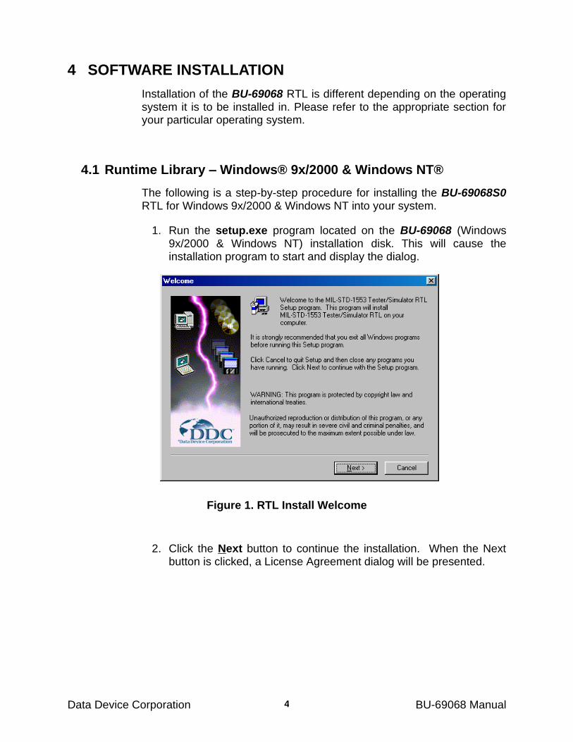
1. Run the setup.exe program located on the BU-69068 (Windows 9x/2000 & Windows NT) installation disk. This will cause the installation program to start and display the dialog.
Figure 1. RTL Install Welcome
2. Click the Next button to continue the installation. When the Next button is clicked, a License Agreement dialog will be presented.
S O F T W A R E I N S T A L L A T I O N
Data Device Corporation BU-69068 Manual 5
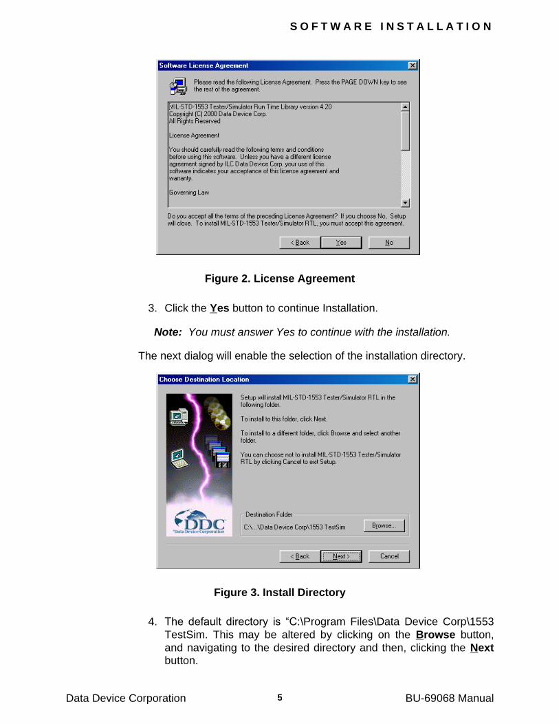
Figure 2. License Agreement
3. Click the Yes button to continue Installation.
Note: You must answer Yes to continue with the installation.
The next dialog will enable the selection of the installation directory.
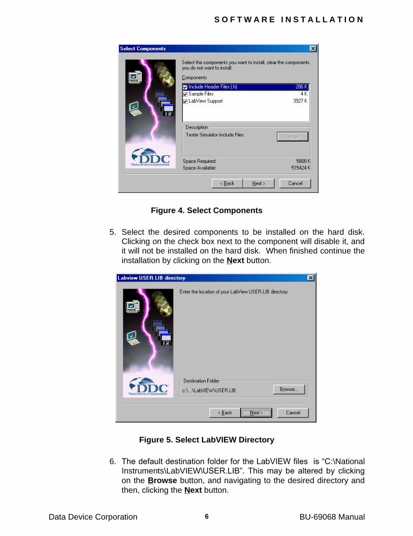
Figure 3. Install Directory
4. The default directory is ―C:\Program Files\Data Device Corp\1553
TestSim. This may be altered by clicking on the Browse button,
and navigating to the desired directory and then, clicking the Next button.
S O F T W A R E I N S T A L L A T I O N
Data Device Corporation BU-69068 Manual 6
Figure 4. Select Components
5. Select the desired components to be installed on the hard disk. Clicking on the check box next to the component will disable it, and it will not be installed on the hard disk. When finished continue the
installation by clicking on the Next button.
Figure 5. Select LabVIEW Directory
6. The default destination folder for the LabVIEW files is ―C:\National Instruments\LabVIEW\USER.LIB‖. This may be altered by clicking
on the Browse button, and navigating to the desired directory and
then, clicking the Next button.
S O F T W A R E I N S T A L L A T I O N
Data Device Corporation BU-69068 Manual 7
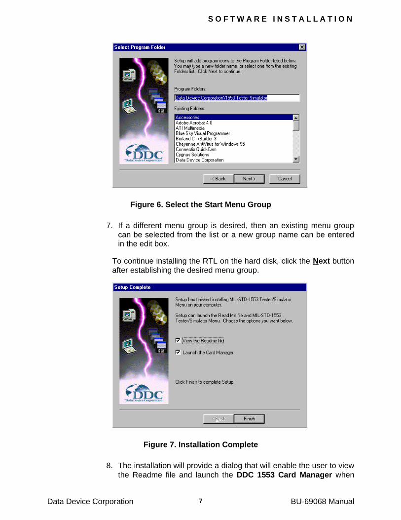
Figure 6. Select the Start Menu Group
7. If a different menu group is desired, then an existing menu group can be selected from the list or a new group name can be entered in the edit box.
To continue installing the RTL on the hard disk, click the Next button after establishing the desired menu group.
Figure 7. Installation Complete
8. The installation will provide a dialog that will enable the user to view
the Readme file and launch the DDC 1553 Card Manager when
S O F T W A R E I N S T A L L A T I O N
Data Device Corporation BU-69068 Manual 8
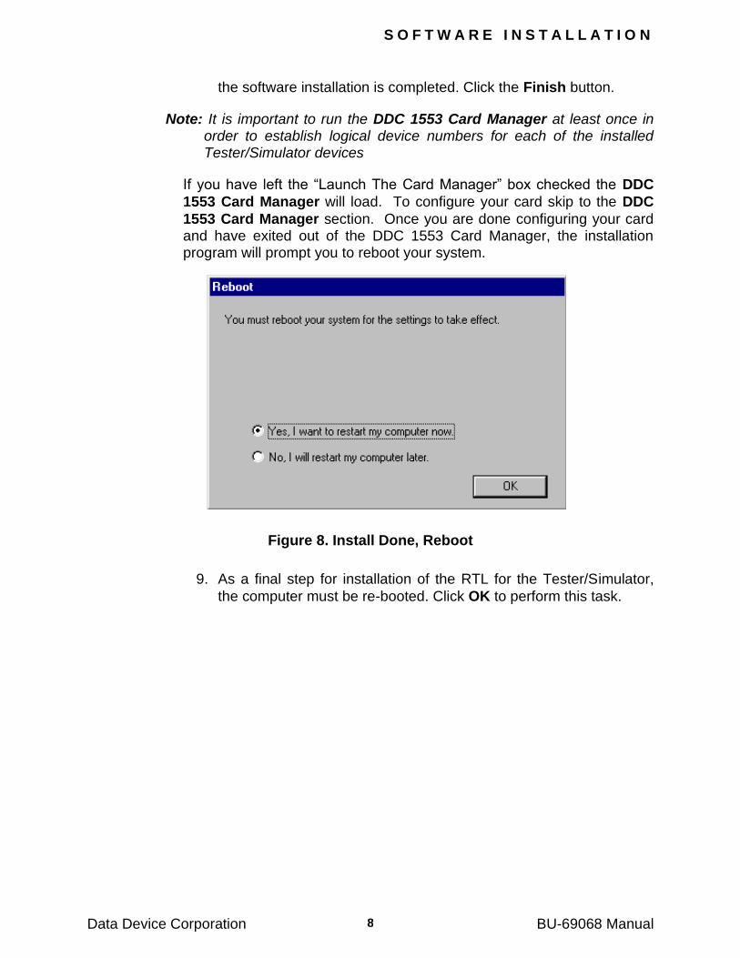
the software installation is completed. Click the Finish button.
Note: It is important to run the DDC 1553 Card Manager at least once in order to establish logical device numbers for each of the installed Tester/Simulator devices
If you have left the ―Launch The Card Manager‖ box checked the DDC
1553 Card Manager will load. To configure your card skip to the DDC
1553 Card Manager section. Once you are done configuring your card and have exited out of the DDC 1553 Card Manager, the installation program will prompt you to reboot your system.
Figure 8. Install Done, Reboot
9. As a final step for installation of the RTL for the Tester/Simulator,
the computer must be re-booted. Click OK to perform this task.
S O F T W A R E I N S T A L L A T I O N
Data Device Corporation BU-69068 Manual 9
4.2 Runtime Library – DOS
4.2.1 DOS Version PCMCIA Requirements
The BU-65570M requires that some form of PCMCIA support be installed on the computer. If Windows 95/98 or Windows NT is being used, then this support is provided natively by the operating system. If
the BU-65570M is going to be used from the Real Mode DOS operating system, then an extension to the operating system must be loaded to provide this function. These Card Services drivers would normally be provided with the PCMCIA socket hardware, and must be installed and operating correctly. This document will provide some card services troubleshooting information, but information pertaining to the installation of the Real Mode DOS Card Services should be provided with the socket hardware.
PCMCIA Release 2.1 (July 1993) represented the culmination of hardware and software enhancements to a specification, which was originally written to standardize memory cards. This final release of the PCMCIA standard defined a hardware interface that is capable of supporting a wide variety of peripheral interfaces. Salient hardware features of the PCMCIA standard include support for memory space, I/O space, wait states, and interrupts. In addition to a flexible hardware interface, the PCMCIA standard also defined a software API aimed at providing plug and play extensions to existing operating systems.
In February 1995 a new standard was released which combined both the PCMCIA Standard and the JEIDA Standard. This new document is referred to as the PC Card Standard. In addition to changing the name of the standard, the PC Card standard added new features, and new card types while maintaining compatibility to PCMCIA release 2.1. For the remainder of this document we will use the terms PC Card and PCMCIA interchangeably to refer to cards designed to meet the PCMCIA 2.1 Standard as well as the PC Card Standard.
The primary role of a Card Services driver is to provide system resource management to drivers for PC Cards. Card Services also provides the services necessary to configure the socket interface to the host computer. When a PC Card is plugged into a computer the memory, I/O, and interrupt for the card are NOT accessible by the host computer. There is a hardware adapter within the computer, referred to a socket controller, which maps the PC Cards memory, I/O, and interrupts into the space of the host computer.
S O F T W A R E I N S T A L L A T I O N
Data Device Corporation BU-69068 Manual 10
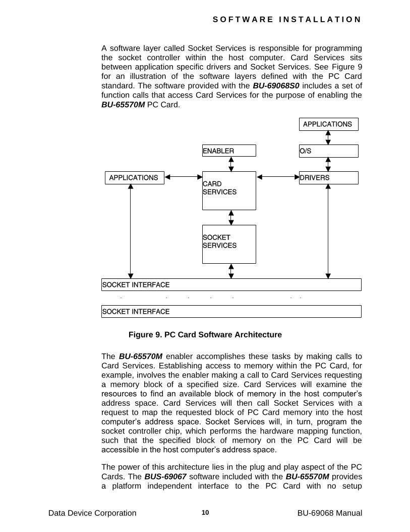
A software layer called Socket Services is responsible for programming the socket controller within the host computer. Card Services sits between application specific drivers and Socket Services. See Figure 9 for an illustration of the software layers defined with the PC Card
standard. The software provided with the BU-69068S0 includes a set of function calls that access Card Services for the purpose of enabling the
BU-65570M PC Card.
Figure 9. PC Card Software Architecture
The BU-65570M enabler accomplishes these tasks by making calls to Card Services. Establishing access to memory within the PC Card, for example, involves the enabler making a call to Card Services requesting a memory block of a specified size. Card Services will examine the resources to find an available block of memory in the host computer‘s address space. Card Services will then call Socket Services with a request to map the requested block of PC Card memory into the host computer‘s address space. Socket Services will, in turn, program the socket controller chip, which performs the hardware mapping function, such that the specified block of memory on the PC Card will be accessible in the host computer‘s address space.
The power of this architecture lies in the plug and play aspect of the PC
Cards. The BUS-69067 software included with the BU-65570M provides a platform independent interface to the PC Card with no setup
S O F T W A R E I N S T A L L A T I O N
Data Device Corporation BU-69068 Manual 11
configuration required. As such, software developed with the BUS-
69067 Library should run on any PC with a Card Services driver compliant to PCMCIA 2.1 or with the PC Card Standard. It is imperative that a Card Services driver be installed and working correctly on the target computer. It should be noted that early releases of Card Services drivers did not implement all functions defined with the PC Card or PCMCIA standard.
All of the information about Card Services may be ignored if the software will be used in a DOS session from Windows 95/98 or Windows NT. These operating systems provide a native card services that will enable
and access the BU-65570M without the need for a second source card services package.
4.2.2 Installing the RTL in DOS
To install the BUS-69067 DOS RTL perform the following step by step procedure:
1. At the ―C:>‖ prompt type:
A:\winstall.exe
2. From the License Agreement screen, press the <Enter> key to accept the agreement.
3. Press any key to begin the installation.
4. Select the drive letter in which you would like to install the RTL. Once the drive letter is set, then enter in the target subdirectory.
5. The autoexec.bat file will need to be updated for the software package to work properly, select whether you would like the software installation to update the file and press the enter key to continue. If you enter ―Yes‖ then the program will add an entry into your autoexec.bat file that creates a new environment variable. If you entered ―No‖, then you should modify this batch file manually by adding the statement:
<SET TESTSIM=yourdrive:\yourdirectory>.
6. The system will now need to be rebooted to incorporate the changes made to the autoexec.bat
4.2.3 Setting Up the BU-65570M In DOS
After the computer has been rebooted, the Readme.txt file should be read. This readme file provides information important to the use of this software product. The software directories installed are INCLUDE, DOSLIB, WIN31LIB, and SAMPLE. The environment variable indicates
S O F T W A R E I N S T A L L A T I O N
Data Device Corporation BU-69068 Manual 12
to the library where the *.RBF and *.IO files are located. These files are
required for proper operation of the BU-65570M, and are only valid for the version of the Tester/Simulator software they are installed with. When new versions of this software are released, the new *.RBF and *.IO files must be used.
For this software to operate correctly and to be enabled by the Card Services driver, the TESTSIM.CFG file must contain a reference to the slot number that the card is inserted into. As a default, the content of this file is simply: ‗slot=0‘. If the card is going to be inserted into slot 1, then the contents of this file should be changed accordingly.
This library is designed to be used with a ‗C‘ compiler, and may be used to develop Windows 3.1 or DOS 16-bit programs
Presently, the BU-69068S0 and BU-69067S0 runtime libraries are written for the Microsoft PC environment. This includes DOS 6.xx, Windows 3.1x, Windows 95/98 and Windows NT. These environments provide a Card Services interface that allows our software access to
memory, I/O ports and interrupt assets for the card. The BU-65570M is PCMCIA 2.0 compliant and supports tuples that direct card services to
allocate resources to the card. The BU-65570M requires 4 bytes of I/O port space that is used as registers to control the card. In addition, the card requires 16K words of memory space and one interrupt that are mapped to the computer‘s assets.
The BU-65570M operates by acquiring the slot number for the card, and then makes resource calls to card services. These calls will request memory, interrupt and I/O resources. When card services receives a call, it will look at the appropriate tuples in the card for the resources required. If the services are available, card services will return handles to the card allowing access to computer assets which are then used by the runtime library.
We do not recommend using the BU-65570M in a computer that is not Intel and Microsoft compatible. This would require porting the runtime library to the computer and extensive knowledge of the operating system, hardware, and the library source. In addition card access to memory, read/write. I/O registers and interrupts would have to be modified.
S O F T W A R E I N S T A L L A T I O N
Data Device Corporation BU-69068 Manual 13
4.3 Runtime Library – Linux®
The installation package consists of a tar/g-zip compressed archive BU69068S1_x_y_z.TGZ where 'x' is the version, ‗y' is the revision, and ‗z' is the release), which must be unzipped as 'root' user. This operation will install all system files required of the package, and produce sample project files and a product information file 'Readme.txt' in the current directory.
Installation instructions are contained in the ‗Install.txt’ file, located on the installation disk. Please note that this is a LINUX ―man page‖ type text file.
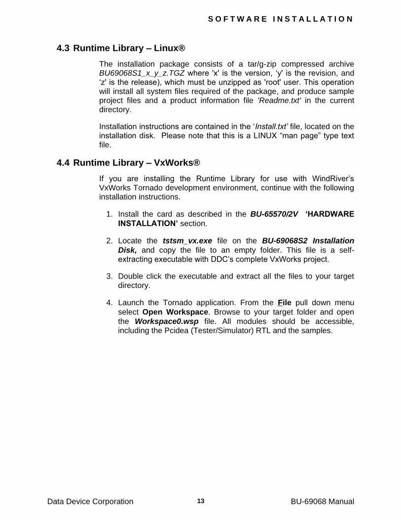
4.4 Runtime Library – VxWorks®
If you are installing the Runtime Library for use with WindRiver‘s VxWorks Tornado development environment, continue with the following installation instructions.
1. Install the card as described in the BU-65570/2V „HARDWARE
INSTALLATION‟ section.
2. Locate the tstsm_vx.exe file on the BU-69068S2 Installation
Disk, and copy the file to an empty folder. This file is a self-extracting executable with DDC‘s complete VxWorks project.
3. Double click the executable and extract all the files to your target directory.
4. Launch the Tornado application. From the File pull down menu
select Open Workspace. Browse to your target folder and open
the Workspace0.wsp file. All modules should be accessible, including the Pcidea (Tester/Simulator) RTL and the samples.
S O F T W A R E I N S T A L L A T I O N
Data Device Corporation BU-69068 Manual
14
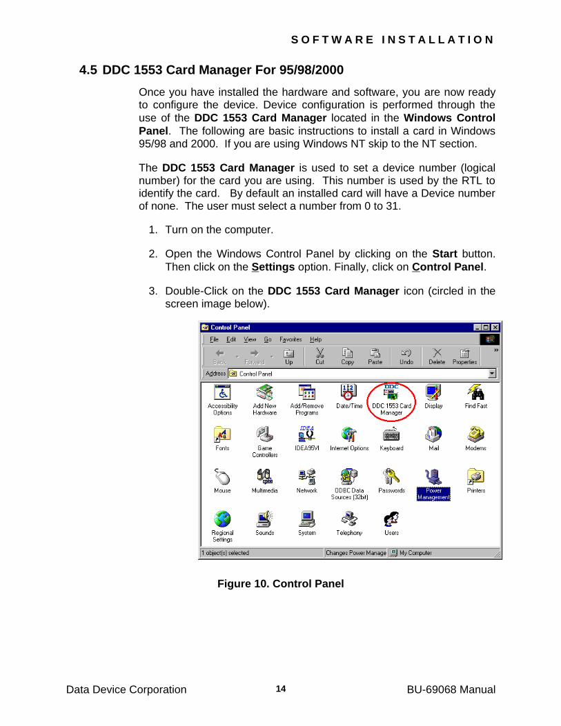
4.5 DDC 1553 Card Manager For 95/98/2000
Once you have installed the hardware and software, you are now ready to configure the device. Device configuration is performed through the
use of the DDC 1553 Card Manager located in the Windows Control
Panel. The following are basic instructions to install a card in Windows 95/98 and 2000. If you are using Windows NT skip to the NT section.
The DDC 1553 Card Manager is used to set a device number (logical number) for the card you are using. This number is used by the RTL to identify the card. By default an installed card will have a Device number of none. The user must select a number from 0 to 31.
1. Turn on the computer.
2. Open the Windows Control Panel by clicking on the Start button.
Then click on the Settings option. Finally, click on Control Panel.
3. Double-Click on the DDC 1553 Card Manager icon (circled in the screen image below).
Figure 10. Control Panel
S O F T W A R E I N S T A L L A T I O N
Data Device Corporation BU-69068 Manual 15
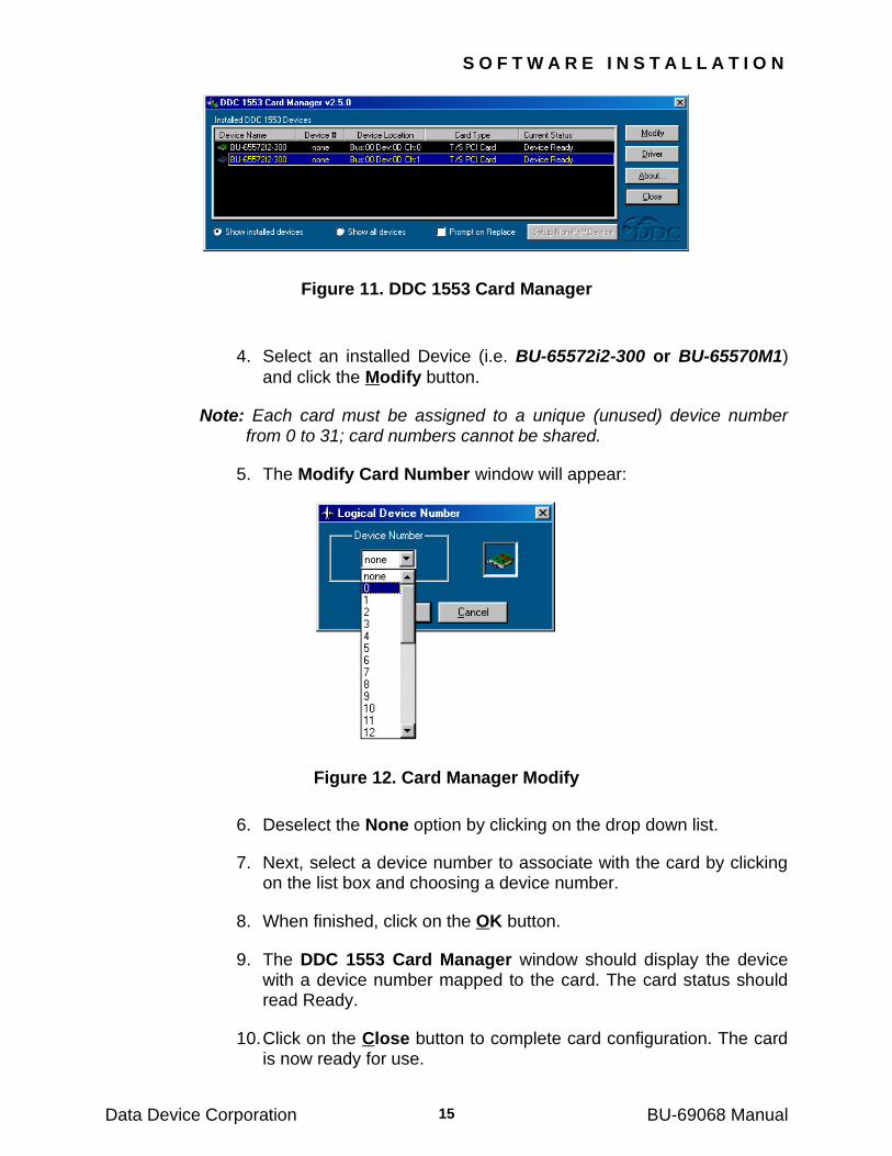
Figure 11. DDC 1553 Card Manager
4. Select an installed Device (i.e. BU-65572i2-300 or BU-65570M1)
and click the Modify button.
Note: Each card must be assigned to a unique (unused) device number from 0 to 31; card numbers cannot be shared.
5. The Modify Card Number window will appear:
Figure 12. Card Manager Modify
6. Deselect the None option by clicking on the drop down list.
7. Next, select a device number to associate with the card by clicking on the list box and choosing a device number.
8. When finished, click on the OK button.
9. The DDC 1553 Card Manager window should display the device with a device number mapped to the card. The card status should read Ready.
10. Click on the Close button to complete card configuration. The card is now ready for use.
S O F T W A R E I N S T A L L A T I O N
Data Device Corporation BU-69068 Manual 16
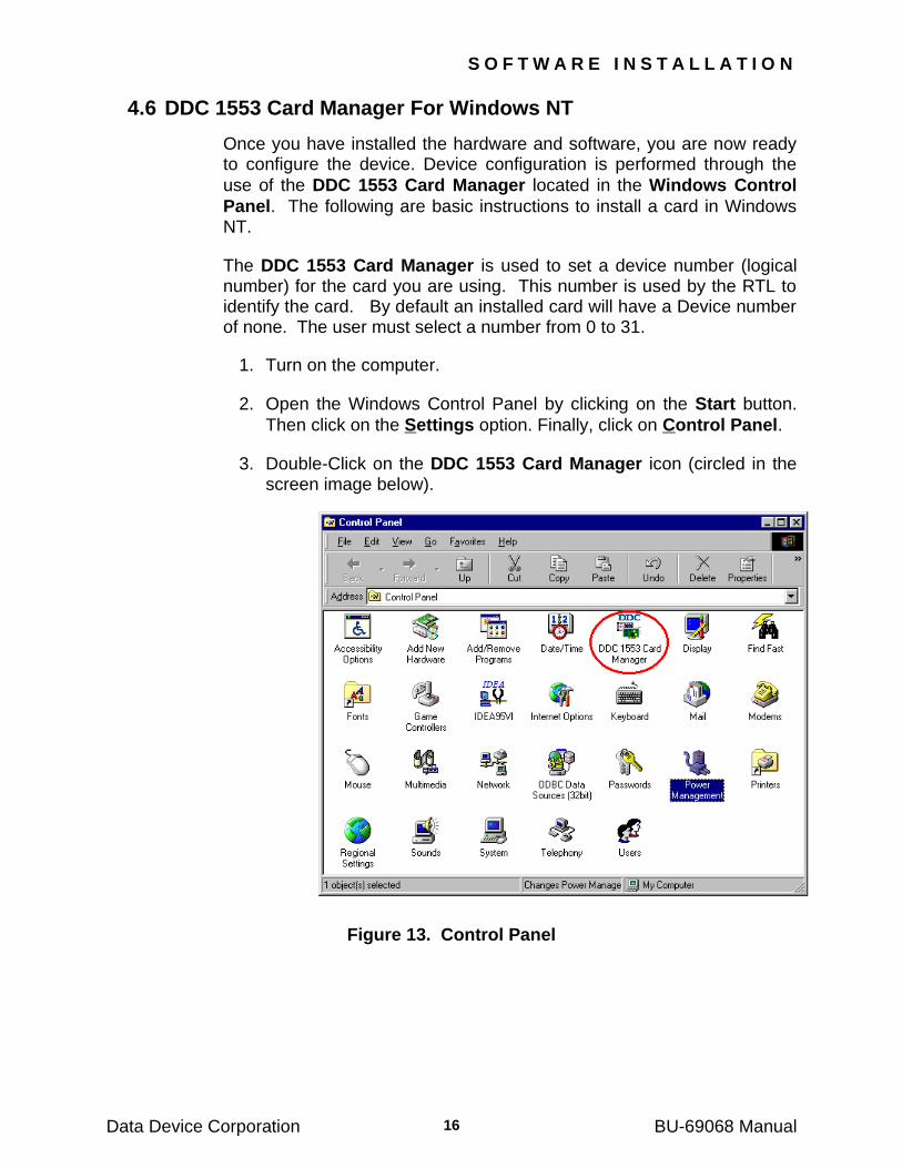
4.6 DDC 1553 Card Manager For Windows NT
Once you have installed the hardware and software, you are now ready to configure the device. Device configuration is performed through the
use of the DDC 1553 Card Manager located in the Windows Control
Panel. The following are basic instructions to install a card in Windows NT.
The DDC 1553 Card Manager is used to set a device number (logical number) for the card you are using. This number is used by the RTL to identify the card. By default an installed card will have a Device number of none. The user must select a number from 0 to 31.
1. Turn on the computer.
2. Open the Windows Control Panel by clicking on the Start button.
Then click on the Settings option. Finally, click on Control Panel.
3. Double-Click on the DDC 1553 Card Manager icon (circled in the screen image below).
Figure 13. Control Panel
S O F T W A R E I N S T A L L A T I O N
Data Device Corporation BU-69068 Manual 17
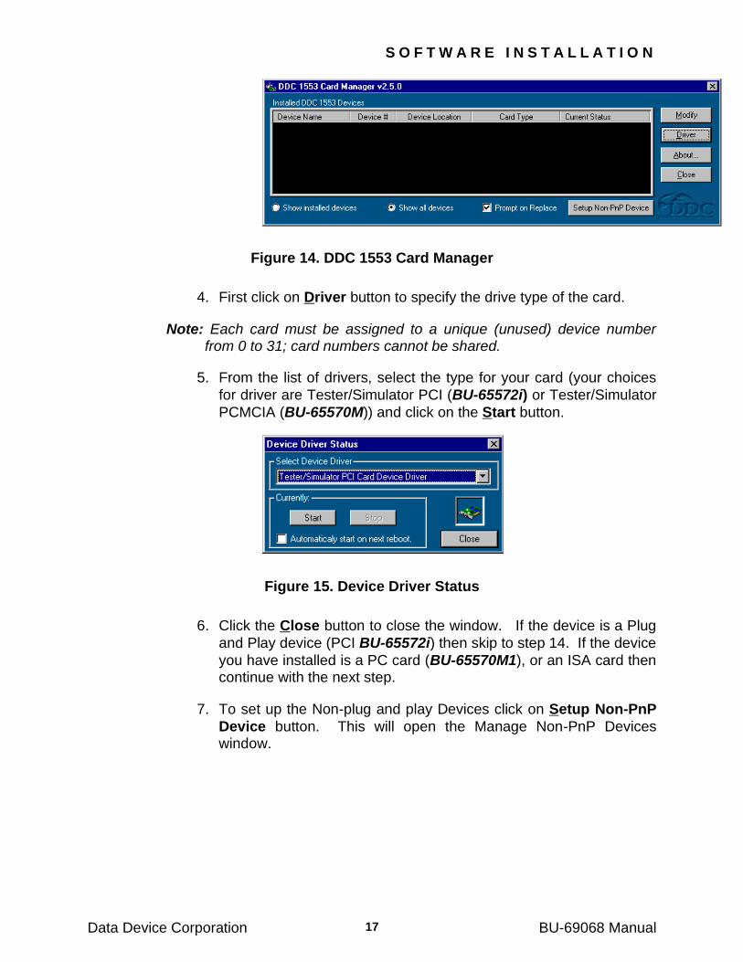
Figure 14. DDC 1553 Card Manager
4. First click on Driver button to specify the drive type of the card.
Note: Each card must be assigned to a unique (unused) device number from 0 to 31; card numbers cannot be shared.
5. From the list of drivers, select the type for your card (your choices
for driver are Tester/Simulator PCI (BU-65572i) or Tester/Simulator
PCMCIA (BU-65570M)) and click on the Start button.
Figure 15. Device Driver Status
6. Click the Close button to close the window. If the device is a Plug
and Play device (PCI BU-65572i) then skip to step 14. If the device
you have installed is a PC card (BU-65570M1), or an ISA card then continue with the next step.
7. To set up the Non-plug and play Devices click on Setup Non-PnP
Device button. This will open the Manage Non-PnP Devices window.
S O F T W A R E I N S T A L L A T I O N
Data Device Corporation BU-69068 Manual 18
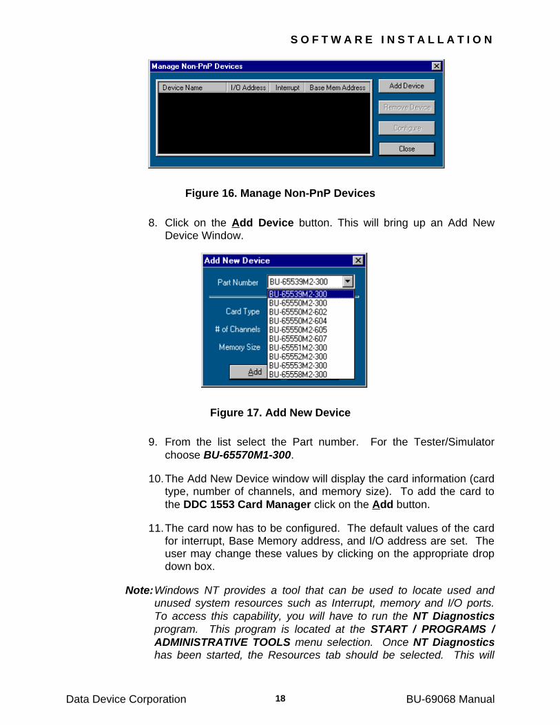
Figure 16. Manage Non-PnP Devices
8. Click on the Add Device button. This will bring up an Add New Device Window.
Figure 17. Add New Device
9. From the list select the Part number. For the Tester/Simulator
choose BU-65570M1-300.
10. The Add New Device window will display the card information (card type, number of channels, and memory size). To add the card to
the DDC 1553 Card Manager click on the Add button.
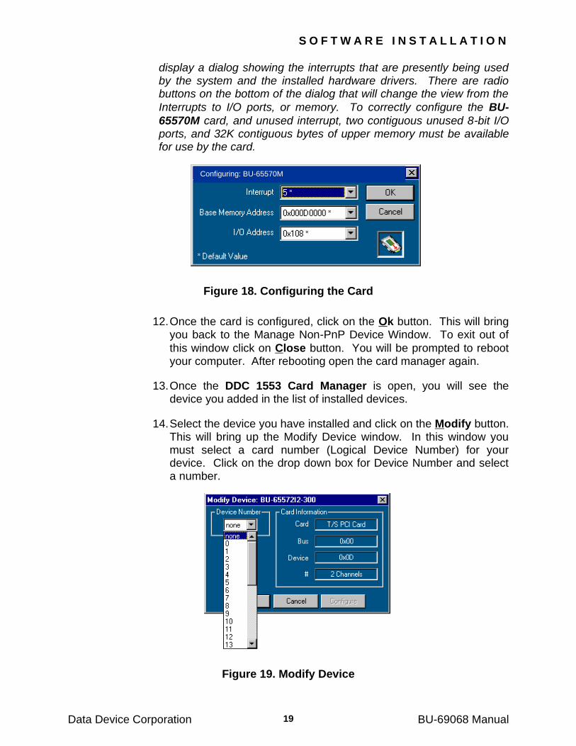
11. The card now has to be configured. The default values of the card for interrupt, Base Memory address, and I/O address are set. The user may change these values by clicking on the appropriate drop down box.
Note: Windows NT provides a tool that can be used to locate used and unused system resources such as Interrupt, memory and I/O ports.
To access this capability, you will have to run the NT Diagnostics
program. This program is located at the START / PROGRAMS /
ADMINISTRATIVE TOOLS menu selection. Once NT Diagnostics has been started, the Resources tab should be selected. This will
S O F T W A R E I N S T A L L A T I O N
Data Device Corporation BU-69068 Manual 19
display a dialog showing the interrupts that are presently being used by the system and the installed hardware drivers. There are radio buttons on the bottom of the dialog that will change the view from the
Interrupts to I/O ports, or memory. To correctly configure the BU-
65570M card, and unused interrupt, two contiguous unused 8-bit I/O ports, and 32K contiguous bytes of upper memory must be available for use by the card.
Figure 18. Configuring the Card
12. Once the card is configured, click on the Ok button. This will bring you back to the Manage Non-PnP Device Window. To exit out of
this window click on Close button. You will be prompted to reboot your computer. After rebooting open the card manager again.
13. Once the DDC 1553 Card Manager is open, you will see the device you added in the list of installed devices.
14. Select the device you have installed and click on the Modify button. This will bring up the Modify Device window. In this window you must select a card number (Logical Device Number) for your device. Click on the drop down box for Device Number and select a number.
Figure 19. Modify Device
Configuring: BU-65570M
S O F T W A R E I N S T A L L A T I O N
Data Device Corporation BU-69068 Manual 20
Note: If a previously assigned device number is selected, and the Prompt
on Replace option is checked on the DDC 1553 Card Manager a
warning will appear. Clicking on Yes will overwrite the previously
assigned device number. If the Prompt on Replace option was not selected, a warning will not be displayed and the new device number will automatically overwrite the previously assigned device number.
15. After selecting a Device Number, click on the Ok button. Your
device is now set and ready to use. To exit out of the DDC 1553
card Manager click on the Close button.
Data Device Corporation BU-69068 Manual
21
5 TESTER/SIMULATOR RTL
5.1 Tester/Simulator RTL (Windows 9x/2000 & Windows NT)
The Tester/Simulator Runtime Library (RTL) is a collection of routines that allow a programmer developing applications for Windows an easy
way of accessing the BU-65570/2i PCI Card, or BU-65570M PC card and use its enhanced features in a simple, easy to understand format.
This functionality is provided in the Windows DLL (testsim32.dll).
5.2 Tester/Simulator RTL (VxWorks, Windows/MXI-II)
The Tester/Simulator Runtime Library (RTL) is a collection of routines that will allow a programmer developing applications for VxWorks or
Windows an easy way of accessing the BU-65570/2V VME/VXI Card, and use its enhanced features in a simple, easy to understand format.
This functionality is provided in the Windows DLL (testsim32.dll) or the
VxWorks driver/library module (pcidea.out). In both cases the API is identical, and it is a simple operation to get software written for the DLL in Windows to work on a VXI chassis either through the MXI-II link or with the VxWorks running on an embedded single board computer.
The 4 modes of operation supported by the RTL are BC, RT, MT, and Replay.
5.2.1 Bus Controller Mode
The Bus Controller mode is used to initiate transmission of messages across the MIL-STD-1553 bus. Listed below are some of the coding techniques used with this mode of operation.
Initialize the card
Create messages and frames
Setup the BC operations
Run the BC
5.2.2 Remote Terminal Mode
The Remote Terminal mode is used to respond to messages sent by the Bus Controller. Listed below are some of the coding techniques used with this mode of operation.
Initialize the card
Create data tables and initialize them with data
T E S T E R / S I M U L A T O R R T L
Data Device Corporation BU-69068 Manual 22
Establish any error responses
Attach interrupt intermessage routines to the data tables
Run the RT
5.2.3 Monitor Mode
The Monitor mode is used to capture messages transmitted across the bus. Listed below are some of the coding techniques used with this mode of operation.
Initialize the card
Setup Message Filter tables
Setup Legalization tables
Specify monitor file for stack storage
Run the MT
5.2.4 Replay Mode
The Replay mode enables an application to replay a previously captured stack file. This can be a stack file from a previous version of DDC Tester/Simulator as well as this version. This version of replay is capable of simultaneously monitoring during replay. Listed below are some of the coding techniques used with this mode of operation.
Initialize the card
Select stack file
Select Remote Terminals that will be emulated by the replay
Select stack file for simultaneous monitor
Run Replay
Data Device Corporation BU-69068 Manual
23
6 HEADER FILES
The header files included with the RTL contain all necessary prototypes, structures, and macros for a program which requires access to the Tester/Simulator‘s RTL‘s routines.
6.1 Type and Structure Definitions
The type, structure, and enumeration declarations are in standard C header files. All required files are included by a single file called TS_drv.h. You should take some time to look at this file and become familiar with its contents. This file will need to be included in your source code whenever you need to declare a structure to be passed to one of our library functions, or when you want to use one of the defined types.
6.2 Function Prototypes
The function prototypes for all functions in the DLL are defined in the standard C header files that will be included by the TS_drv.h file.
6.3 Initialization
In order for the library to function properly, some internal variables must
be initialized, and the downloadable software that runs on the BU-
65570/2i PCI card, BU-65570/2v VME/VXI card, and BU-65570M PC card must be loaded into the card‘s memory.
6.3.1 Initializing The DLL Functionality
Prior to any other function calls from the DLL, the function ddcResetCard
must be called. This function must be called once for each BU-65570/2i
PCI card, BU-65570/2v VME/VXI card, or BU-65570M PC card installed in the PC. It loads the executable hex file to the card, and runs power-up diagnostics (as directed by the user).
6.4 Multiple Card Functions
All DLL operations take a parameter in the function call that specifies the initialized card (device) on which the function should be performed.
H E A D E R F I L E S
Data Device Corporation BU-69068 Manual 24
6.5 Generating PC Interrupts
The BU-65570/2I PCI card, BU-65570/2v VME/VXI card and the BU-
65570M PC card are capable of generating PC Interrupts. The PCI cards generate interrupts on the #INTA interrupt line. All interrupts on multiple channels will use the same interrupt line.
Interrupts are generated based on inter-message routines that can be specified per BC message, RT data table, or on a Monitor circular buffer being 1/3 full.
When the appropriate action occurs, the hardware will generate an interrupt to the device driver. The device driver is capable of queuing up a maximum of 64 interrupts. This provides some elasticity to the interrupt operations.
6.6 Diagnostic Functions
Following the issuance of a reset command, on-board diagnostics are performed. This routine will determine the level and details of a failure.
Data Device Corporation BU-69068 Manual
25
7 CONFIGURING THE VXWORKS RTL
The VxWorks version of the Tester/Simulator RTL (BU-69068S2) uses special function calls to scan for all cards residing in the system. Once a card is found, all memory and interrupt resources are configured and
enabled. The function ddcVxCreateDevs performs the scanning and configuring of the card. During configuration, each channel of each card resident on the system will be matched up with a unique identifier or
logical device number. The sample program sEnumCards displays all valid logical device numbers and their physical location in the system.
7.1 Setting Card Resources For Your System
The memory ranges that the RTL uses to configure the card are specific to the system. The default memory ranges are set as the following:
A24: Base address - 0x00000000, Size - 16MB
A32: Base address - 0x08000000, Size - 128MB
The function ddcVxSetVMEAddressInfo can be used to change the free memory ranges to meet the requirements of a specific system and to force cards to be configured to a certain area of memory.
The interrupt vector on the single board computer‘s PCI bus and the interrupt level on the VME bus must be given to the RTL for the card to service interrupts properly. For an MV2700 Power PC SBC the interrupt vector for the PCI-VME interface is 0x15. This number is specific to the system and should be given in the documentation of the single board computer you are using. The VME interrupt level used by the card can be any number between 1 and 7.
Below is an example of how to configure a system containing a Tester/Simulator VXI card to use VME interrupt level #2 using a MV2700 Power PC SBC.
U16BIT wIrqLevel = 0x0215; /* VME IRQ=2, PCI IRQ=0x15*/
ddcVxCreateDevs(wIrqLevel);
The VME interrupt level is the first 8 bits of the wIrqLevel parameter and the PCI interrupt vector is the lower 8 bits.
7.2 Setting the Firmware Pathnames
The RTL needs access to 2 files for the card to work properly. The files
are Bu65558.i0 and A71594.rbf. The pathnames are hardcoded in the

C O N F I G U R I N G T H E V X W O R K S R T L
Data Device Corporation BU-69068 Manual 26
VxWorks.c file to be "e:\\projects\\vxworks\\pcidea‖. Before running the RTL these pathnames should be changed to match the host system and the RTL should then be recompiled.
7.3 Interrupt Handling
The BU-65570/2V VME/VXI card is capable of generating VME
Interrupts. The BU-65570/2V generates interrupts on one of the 7 interrupt lines (IRQ1 through IRQ7). When running MXI-II systems a special interrupt manager will handle the Interrupts generated by the cards.
Interrupts are generated based on intermessage routines that can be specified per BC message, RT data table, or on a Monitor circular buffer being 1/3 full.
When the appropriate action occurs, the hardware will generate the interrupt. The hardware is capable of queuing up a maximum of 64 interrupts. This provides some elasticity to the interrupt operations.
When either a BC/RT or Monitor interrupt request is generated, the RTL clears the interrupt and runs the appropriate user routine (defined using
ddcSetMonEvent and ddcSetBcrtEvent).
The user "mon_event_handler" has no arguments. The RTL interrupt handler passes two arguments to the user "bcrt_event_handler". The inputs are defined as follows:
U16BIT vector_type - the first word of the interrupt vector
U16BIT vector_parameter - the second word of the interrupt vector
7.4 Monitor Interrupts
The Monitor can request 2 types of interrupts:
An interrupt after each message
An interrupt after 1/3 of the Monitor's circular buffer has been filled (approximately 4K words)
Only one Monitor interrupt type may be enabled; bits 14 and 15 in the INTERRUPT MASK are used to enable/disable the interrupts.
If Monitor interrupts are enabled, then the Monitor will also issue an
interrupt when it is halted by ddcHaltMon or ddcHaltIdea. This interrupt can be used to read the "tail-end" of the card's circular buffer (see
routines ddcReadMonStack and ddcReadMonStackPart). Each time the Monitor requests an interrupt it increments a counter. If a similar
C O N F I G U R I N G T H E V X W O R K S R T L
Data Device Corporation BU-69068 Manual 27
counter is incremented by the user, its value can be compared to the card's counter in order to detect lost interrupts.
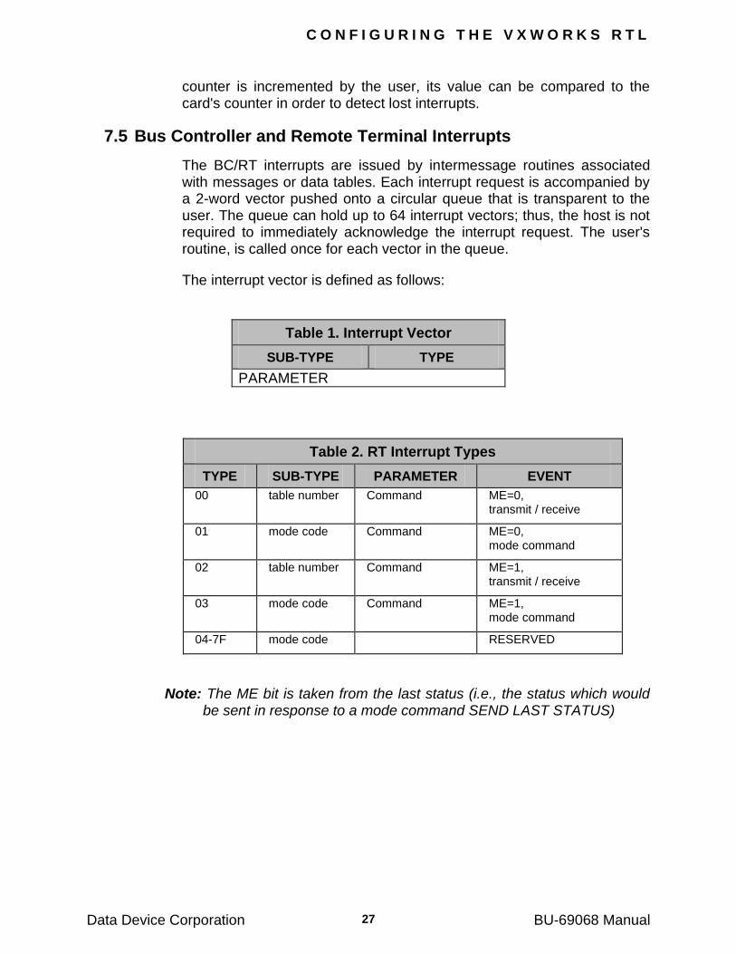
7.5 Bus Controller and Remote Terminal Interrupts
The BC/RT interrupts are issued by intermessage routines associated with messages or data tables. Each interrupt request is accompanied by a 2-word vector pushed onto a circular queue that is transparent to the user. The queue can hold up to 64 interrupt vectors; thus, the host is not required to immediately acknowledge the interrupt request. The user's routine, is called once for each vector in the queue.
The interrupt vector is defined as follows:
Table 1. Interrupt Vector
SUB-TYPE TYPE
PARAMETER
Table 2. RT Interrupt Types
TYPE SUB-TYPE PARAMETER EVENT
00 table number Command ME=0, transmit / receive
01 mode code Command ME=0, mode command
02 table number Command ME=1, transmit / receive
03 mode code Command ME=1, mode command
04-7F mode code RESERVED
Note: The ME bit is taken from the last status (i.e., the status which would be sent in response to a mode command SEND LAST STATUS)
C O N F I G U R I N G T H E V X W O R K S R T L
Data Device Corporation BU-69068 Manual 28
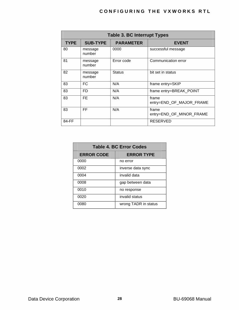
Table 3. BC Interrupt Types
TYPE SUB-TYPE PARAMETER EVENT
80 message number
0000 successful message
81 message number
Error code Communication error
82 message number
Status bit set in status
83 FC N/A frame entry=SKIP
83 FD N/A frame entry=BREAK_POINT
83 FE N/A frame entry=END_OF_MAJOR_FRAME
83 FF N/A frame entry=END_OF_MINOR_FRAME
84-FF RESERVED
Table 4. BC Error Codes
ERROR CODE ERROR TYPE
0000 no error
0002 inverse data sync
0004 invalid data
0008 gap between data
0010 no response
0020 invalid status
0080 wrong TADR in status
C O N F I G U R I N G T H E V X W O R K S R T L
Data Device Corporation BU-69068 Manual 29
7.6 Interrupt Mask
The INTERRUPT MASK is a 16-bit word that resides in the BC/RT and Monitor shared memories. Each bit in the mask, when set to "1", inhibits a unique interrupt type.
Table 5. Interrupt Mask
MASK BIT INTERRUPT TYPE
0 00
1 01
2 02
3 03
4 80
5 81
6 82
7 83
8 XX
9 XX
10 XX
11 XX
12 XX
13 XX
14 1/3 of Circular Buffer (Monitor)
15 End of Msg (Monitor)
Data Device Corporation BU-69068 Manual
30
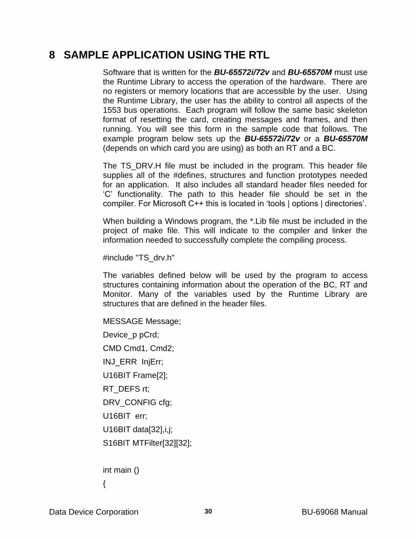
8 SAMPLE APPLICATION USING THE RTL
Software that is written for the BU-65572i/72v and BU-65570M must use the Runtime Library to access the operation of the hardware. There are no registers or memory locations that are accessible by the user. Using the Runtime Library, the user has the ability to control all aspects of the 1553 bus operations. Each program will follow the same basic skeleton format of resetting the card, creating messages and frames, and then running. You will see this form in the sample code that follows. The
example program below sets up the BU-65572i/72v or a BU-65570M (depends on which card you are using) as both an RT and a BC.
The TS_DRV.H file must be included in the program. This header file supplies all of the #defines, structures and function prototypes needed for an application. It also includes all standard header files needed for ‗C‘ functionality. The path to this header file should be set in the compiler. For Microsoft C++ this is located in ‗tools | options | directories‘.
When building a Windows program, the *.Lib file must be included in the project of make file. This will indicate to the compiler and linker the information needed to successfully complete the compiling process.
#include "TS_drv.h"
The variables defined below will be used by the program to access structures containing information about the operation of the BC, RT and Monitor. Many of the variables used by the Runtime Library are structures that are defined in the header files.
MESSAGE Message;
Device_p pCrd;
CMD Cmd1, Cmd2;
INJ_ERR InjErr;
U16BIT Frame[2];
RT_DEFS rt;
DRV_CONFIG cfg;
U16BIT err;
U16BIT data[32],i,j;
S16BIT MTFilter[32][32];
int main ()
{
S A M P L E A P P L I C A T I O N U S I N G T H E R T L
Data Device Corporation BU-69068 Manual 31
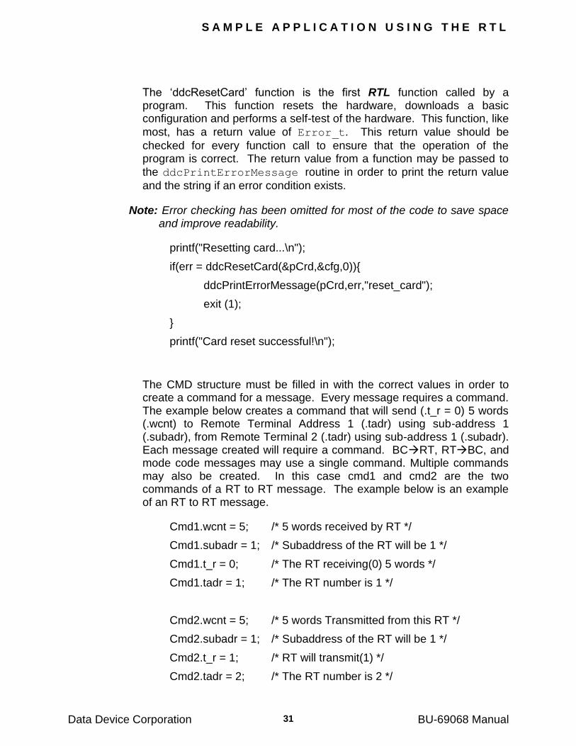
The ‗ddcResetCard‘ function is the first RTL function called by a program. This function resets the hardware, downloads a basic configuration and performs a self-test of the hardware. This function, like
most, has a return value of Error_t. This return value should be
checked for every function call to ensure that the operation of the program is correct. The return value from a function may be passed to
the ddcPrintErrorMessage routine in order to print the return value
and the string if an error condition exists.
Note: Error checking has been omitted for most of the code to save space and improve readability.
printf("Resetting card...\n");
if(err = ddcResetCard(&pCrd,&cfg,0)){
ddcPrintErrorMessage(pCrd,err,"reset_card");
exit (1);
}
printf("Card reset successful!\n");
The CMD structure must be filled in with the correct values in order to create a command for a message. Every message requires a command. The example below creates a command that will send (.t_r = 0) 5 words (.wcnt) to Remote Terminal Address 1 (.tadr) using sub-address 1 (.subadr), from Remote Terminal 2 (.tadr) using sub-address 1 (.subadr). Each message created will require a command. BCRT, RTBC, and mode code messages may use a single command. Multiple commands may also be created. In this case cmd1 and cmd2 are the two commands of a RT to RT message. The example below is an example of an RT to RT message.
Cmd1.wcnt = 5; /* 5 words received by RT */
Cmd1.subadr = 1; /* Subaddress of the RT will be 1 */
Cmd1.t_r = 0; /* The RT receiving(0) 5 words */
Cmd1.tadr = 1; /* The RT number is 1 */
Cmd2.wcnt = 5; /* 5 words Transmitted from this RT */
Cmd2.subadr = 1; /* Subaddress of the RT will be 1 */
Cmd2.t_r = 1; /* RT will transmit(1) */
Cmd2.tadr = 2; /* The RT number is 2 */
S A M P L E A P P L I C A T I O N U S I N G T H E R T L
Data Device Corporation BU-69068 Manual 32
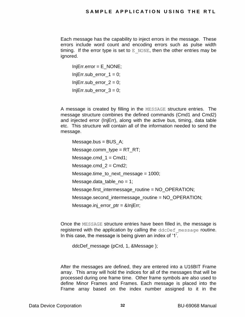
Each message has the capability to inject errors in the message. These errors include word count and encoding errors such as pulse width
timing. If the error type is set to E_NONE, then the other entries may be
ignored.
InjErr.error = E_NONE;
InjErr.sub_error_1 = 0;
InjErr.sub_error_2 = 0;
InjErr.sub_error_3 = 0;
A message is created by filling in the MESSAGE structure entries. The
message structure combines the defined commands (Cmd1 and Cmd2) and injected error (InjErr), along with the active bus, timing, data table etc. This structure will contain all of the information needed to send the message.
Message.bus = BUS_A;
Message.comm_type = RT_RT;
Message.cmd_1 = Cmd1;
Message.cmd_2 = Cmd2;
Message.time_to_next_message = 1000;
Message.data_table_no = 1;
Message.first_intermessage_routine = NO_OPERATION;
Message.second_intermessage_routine = NO_OPERATION;
Message.inj_error_ptr = &InjErr;
Once the MESSAGE structure entries have been filled in, the message is
registered with the application by calling the ddcDef_message routine.
In this case, the message is being given an index of ‗1‘.
ddcDef_message (pCrd, 1, &Message );
After the messages are defined, they are entered into a U16BIT Frame array. This array will hold the indices for all of the messages that will be processed during one frame time. Other frame symbols are also used to define Minor Frames and Frames. Each message is placed into the Frame array based on the index number assigned to it in the
S A M P L E A P P L I C A T I O N U S I N G T H E R T L
Data Device Corporation BU-69068 Manual 33
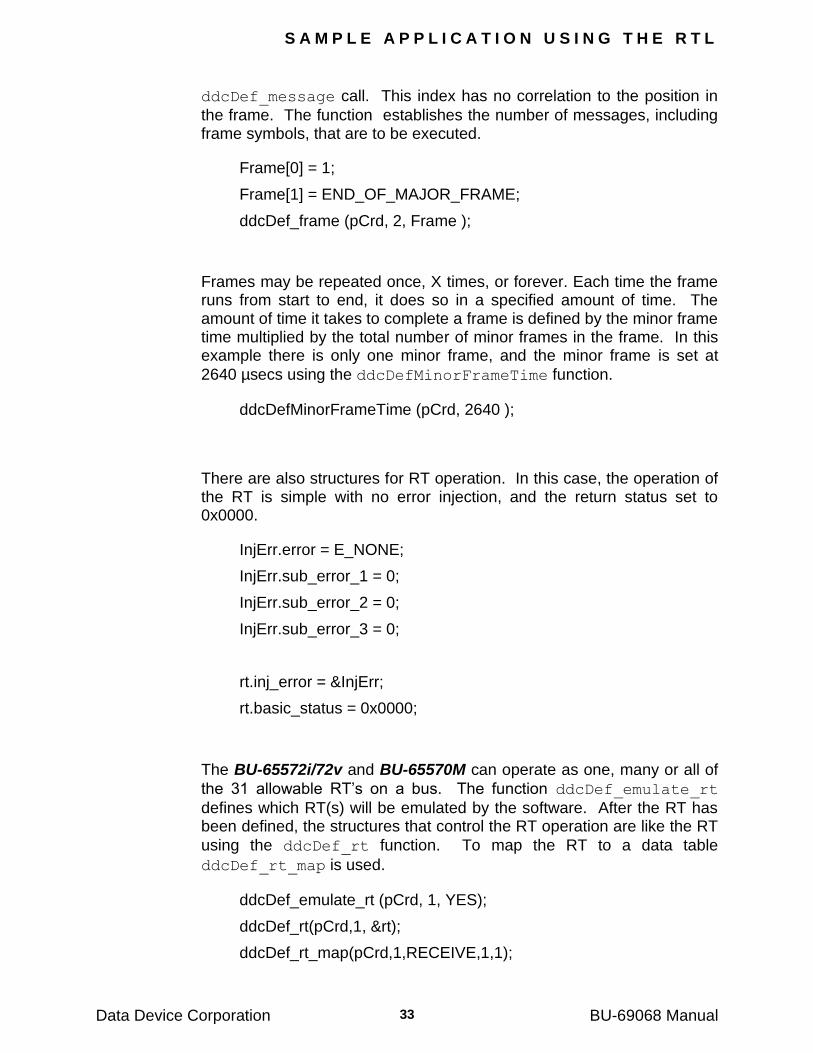
ddcDef_message call. This index has no correlation to the position in
the frame. The function establishes the number of messages, including frame symbols, that are to be executed.
Frame[0] = 1;
Frame[1] = END_OF_MAJOR_FRAME;
ddcDef_frame (pCrd, 2, Frame );
Frames may be repeated once, X times, or forever. Each time the frame runs from start to end, it does so in a specified amount of time. The amount of time it takes to complete a frame is defined by the minor frame time multiplied by the total number of minor frames in the frame. In this example there is only one minor frame, and the minor frame is set at
2640 µsecs using the ddcDefMinorFrameTime function.
ddcDefMinorFrameTime (pCrd, 2640 );
There are also structures for RT operation. In this case, the operation of the RT is simple with no error injection, and the return status set to 0x0000.
InjErr.error = E_NONE;
InjErr.sub_error_1 = 0;
InjErr.sub_error_2 = 0;
InjErr.sub_error_3 = 0;
rt.inj_error = &InjErr;
rt.basic_status = 0x0000;
The BU-65572i/72v and BU-65570M can operate as one, many or all of
the 31 allowable RT‘s on a bus. The function ddcDef_emulate_rt
defines which RT(s) will be emulated by the software. After the RT has been defined, the structures that control the RT operation are like the RT
using the ddcDef_rt function. To map the RT to a data table
ddcDef_rt_map is used.
ddcDef_emulate_rt (pCrd, 1, YES);
ddcDef_rt(pCrd,1, &rt);
ddcDef_rt_map(pCrd,1,RECEIVE,1,1);
S A M P L E A P P L I C A T I O N U S I N G T H E R T L
Data Device Corporation BU-69068 Manual 34
Set up RT 2 since you are doing a RT-RT message. This setup is the
same as RT 1, except when you call ddcDef_rt_map the second
parameter becomes a 2 for RT 2, and the third parameter is TRANSMIT.
InjErr.error = E_NONE;
InjErr.sub_error_1 = 0;
InjErr.sub_error_2 = 0;
InjErr.sub_error_3 = 0;
rt.inj_error = &InjErr;
rt.basic_status = 0x0000;
ddcDef_emulate_rt (pCrd, 2, YES);
ddcDef_rt(pCrd,2, &rt);
ddcDef_rt_map(pCrd,2,TRANSMIT,1,1);
Now you will set up the Data tables for RT 1 and RT 2. The function
ddcDef_table_size sets the size of the data table (third parameter –
5), for the specified data table (second parameter – 1). Then
ddcWrite_data is called to write the data to data table 1.
ddcDef_table_size(pCrd,1,5);
data[ 0]=0x0000; data[1]=0x0001; data[2]=0x0002; data[3]=0x0003; data[4]=0x0004;
ddcWrite_data(pCrd,1,data,5,1);
Setup data table two.
ddcDef_table_size(pCrd,2,5);
data[0]=0x0000; data[1]=0x0001; data[2]=0x0002; data[3]=0x0003; data[4]=0x0004;
ddcWrite_data(pCrd,2,data,5,1);
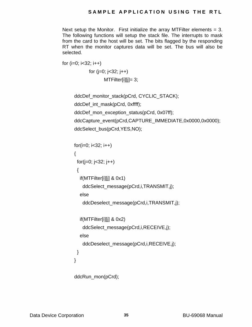
S A M P L E A P P L I C A T I O N U S I N G T H E R T L
Data Device Corporation BU-69068 Manual 35
Next setup the Monitor. First initialize the array MTFilter elements = 3. The following functions will setup the stack file. The interrupts to mask from the card to the host will be set. The bits flagged by the responding RT when the monitor captures data will be set. The bus will also be selected.
for (i=0; i<32; i++)
for (j=0; j<32; j++)
MTFilter[i][j]= 3;
ddcDef_monitor_stack(pCrd, CYCLIC_STACK);
ddcDef_int_mask(pCrd, 0xffff);
ddcDef_mon_exception_status(pCrd, 0x07ff);
ddcCapture_event(pCrd,CAPTURE_IMMEDIATE,0x0000,0x0000);
ddcSelect_bus(pCrd,YES,NO);
for(i=0; i<32; i++)
{
for(j=0; j<32; j++)
{
if(MTFilter[i][j] & 0x1)
ddcSelect_message(pCrd,i,TRANSMIT,j);
else
ddcDeselect_message(pCrd,i,TRANSMIT,j);
if(MTFilter[i][j] & 0x2)
ddcSelect_message(pCrd,i,RECEIVE,j);
else
ddcDeselect_message(pCrd,i,RECEIVE,j);
}
}
ddcRun_mon(pCrd);
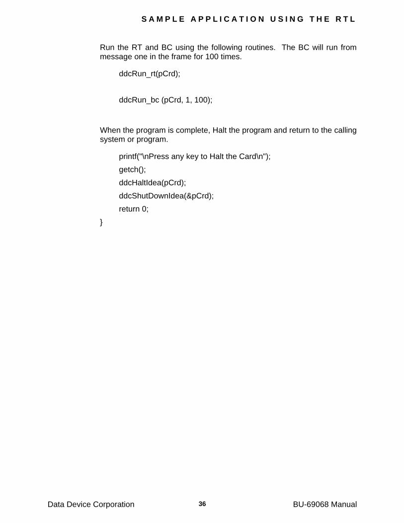
S A M P L E A P P L I C A T I O N U S I N G T H E R T L
Data Device Corporation BU-69068 Manual 36
Run the RT and BC using the following routines. The BC will run from message one in the frame for 100 times.
ddcRun_rt(pCrd);
ddcRun_bc (pCrd, 1, 100);
When the program is complete, Halt the program and return to the calling system or program.
printf("\nPress any key to Halt the Card\n");
getch();
ddcHaltIdea(pCrd);
ddcShutDownIdea(&pCrd);
return 0;
}
Data Device Corporation BU-69068 Manual
37
9 PROGRAMMER‟S REFERENCE
This material describes the software design and operation of the
BU-65570/2i PCI Card, BU-65570/2v VME/VXI Card or a BU-65570M PC Card. This information is provided for users who want to create their own applications using the RTL software provided with the card. If you
are not using the RTL software (BU-69068 or BU-69067) provided with the card, you do not need to read this chapter.
Each channel of the BU-65570/2i PCI card and BU-65570/2v uses a TI-TMS320C57 microprocessor operating at 40 MHz. There are total of 128 Kbytes of RAM on the card for each of the installed channels. 64K bytes are used for program storage and execution, booting the microprocessor and for simple diagnostic tests. The other 64K Kbytes of RAM are provided for use by the 1553 operations.
The cards provide up to four MIL-STD-1553 buses that operate independently. There are relays for each channel that may be accessed via the RTL. These relays enable the application to control the connection to the 1553 bus in either direct or transformer coupled modes.
There is also a set of relays for each installed channel that can be used to setup the 1553 bus loading. The relays allow no load, half load (75 ohms) or full load (37.5 ohms).
The BU-65572i/72v and BU-65570M are IRIG capable. The IRIG is selectable for each channel. If IRIG is specified for a channel, the complete time tag for the channel will be the IRIG time plus the card‘s internal 32-bit time tag. If the IRIG time is not used, then the time tag will be the internal 32-bit time only.
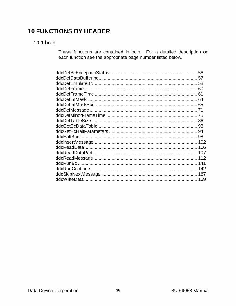
Data Device Corporation BU-69068 Manual
38
10 FUNCTIONS BY HEADER
10.1 bc.h
These functions are contained in bc.h. For a detailed description on each function see the appropriate page number listed below.
ddcDefBcExceptionStatus ................................................................... 56 ddcDefDataBuffering............................................................................ 57 ddcDefEmulateBc ................................................................................ 58 ddcDefFrame ....................................................................................... 60 ddcDefFrameTime ............................................................................... 61 ddcDefIntMask .................................................................................... 64 ddcDefIntMaskBcrt .............................................................................. 65 ddcDefMessage ................................................................................... 71 ddcDefMinorFrameTime ...................................................................... 75 ddcDefTableSize ................................................................................. 86 ddcGetBcDataTable ............................................................................ 93 ddcGetBcHaltParameters .................................................................... 94 ddcHaltBcrt .......................................................................................... 98 ddcInsertMessage ............................................................................... 102 ddcReadData ....................................................................................... 106 ddcReadDataPart ................................................................................ 107 ddcReadMessage ................................................................................ 112 ddcRunBc ............................................................................................ 141 ddcRunContinue .................................................................................. 142 ddcSkipNextMessage .......................................................................... 167 ddcWriteData ....................................................................................... 169
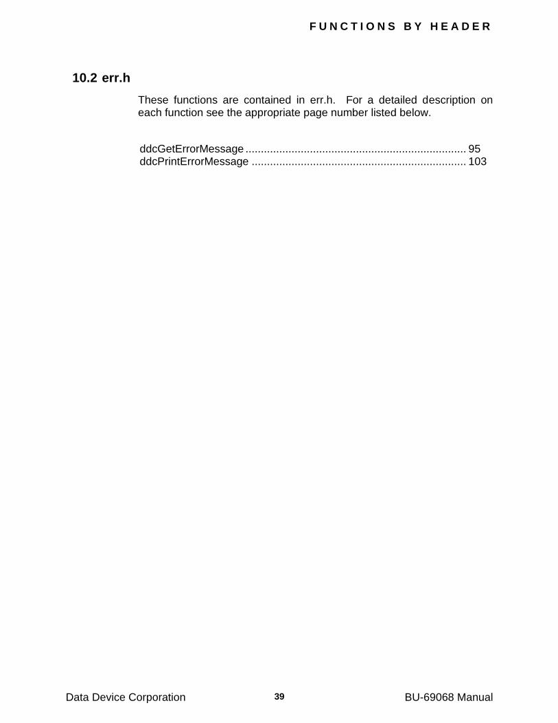
F U N C T I O N S B Y H E A D E R
Data Device Corporation BU-69068 Manual 39
10.2 err.h
These functions are contained in err.h. For a detailed description on each function see the appropriate page number listed below.
ddcGetErrorMessage ........................................................................ 95 ddcPrintErrorMessage ...................................................................... 103
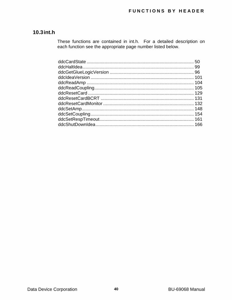
F U N C T I O N S B Y H E A D E R
Data Device Corporation BU-69068 Manual 40
10.3 int.h
These functions are contained in int.h. For a detailed description on each function see the appropriate page number listed below.
ddcCardState .................................................................................... 50 ddcHaltIdea ....................................................................................... 99 ddcGetGlueLogicVersion .................................................................. 96 ddcIdeaVersion ................................................................................. 101 ddcReadAmp .................................................................................... 104 ddcReadCoupling .............................................................................. 105 ddcResetCard ................................................................................... 129 ddcResetCardBCRT ......................................................................... 131 ddcResetCardMonitor ....................................................................... 132 ddcSetAmp........................................................................................ 148 ddcSetCoupling ................................................................................. 154 ddcSetRespTimeout .......................................................................... 161 ddcShutDownIdea ............................................................................. 166
F U N C T I O N S B Y H E A D E R
Data Device Corporation BU-69068 Manual 41
10.4 irq.h
These functions are contained in irq.h. For a detailed description on each function see the appropriate page number listed below.
ddcSetBcrtEvent ............................................................................... 149 ddcSetBcrtEventEx ........................................................................... 150 ddcSetMonEvent ............................................................................... 159
F U N C T I O N S B Y H E A D E R
Data Device Corporation BU-69068 Manual 42
10.5 mt.h
These functions are contained in mt.h. For a detailed description on each function see the appropriate page number listed below.
ddcCaptureEvent .............................................................................. 47 ddcCaptureOccurred ......................................................................... 49 ddcDecodeMonMessage .................................................................. 52 ddcDefIntMaskMonitor ...................................................................... 66 ddcDefMonExceptionStatus .............................................................. 78 ddcDefMonitorStack .......................................................................... 79 ddcDeselectAllMessages .................................................................. 87 ddcDeselectMessage ........................................................................ 88 ddcDisableDma ................................................................................. 89 ddcEnableDma .................................................................................. 90 ddcEnableIrig .................................................................................... 91 ddcFlushDmaBuffer .......................................................................... 92 ddcGetMTCounters ........................................................................... 97 ddcHaltMon ....................................................................................... 100 ddcReadDmaStack ........................................................................... 108 ddcReadIrig ....................................................................................... 109 ddcReadLastMonMessage ............................................................... 110 ddcReadMonRtc ............................................................................... 116 ddcReadMonStack ............................................................................ 117 ddcReadMonStackPart ..................................................................... 118 ddcResetMon .................................................................................... 136 ddcRunMon ....................................................................................... 143 ddcSelectAllMessages ...................................................................... 145 ddcSelectBus .................................................................................... 146 ddcSelectMessage ............................................................................ 147 ddcSetIrig .......................................................................................... 157
F U N C T I O N S B Y H E A D E R
Data Device Corporation BU-69068 Manual 43
10.6 rep.h
These functions are contained in rep.h. For a detailed description on each function see the appropriate page number listed below.
ddcReplayFillStack ............................................................................ 120 ddcReplayReset ................................................................................ 121 ddcReplayRTActive ........................................................................... 122 ddcReplayRunBC .............................................................................. 123 ddcReplayRunRTs ............................................................................ 124 ddcReplaySetRespDelay .................................................................. 125
F U N C T I O N S B Y H E A D E R
Data Device Corporation BU-69068 Manual 44
10.7 rt.h
These functions are contained in rt.h. For a detailed description on each function see the appropriate page number listed below.
ddcDefEmulateRt .............................................................................. 59 ddcDefIntCmdTemplate .................................................................... 63 ddcDefLastCmd ................................................................................ 67 ddcDefLastStatus .............................................................................. 68 ddcDefLegalityBcst ........................................................................... 69 ddcDefLegalityDetection ................................................................... 70 ddcDefModeLegality ......................................................................... 76 ddcDefModeRoutine ......................................................................... 77 ddcDefRt ........................................................................................... 80 ddcDefRtMap .................................................................................... 82 ddcDefRtMapBlock ........................................................................... 83 ddcDefTableRoutine ......................................................................... 85 ddcReadLastStatusCmd ................................................................... 111 ddcReadModeData ........................................................................... 115 ddcReadTimeTags ............................................................................ 119 ddcResetBroadcast ........................................................................... 126 ddcResetBusy ................................................................................... 127 ddcResetBusySetSrq ........................................................................ 128 ddcResetDBCAcceptance ................................................................. 133 ddcResetInstrumentation .................................................................. 134 ddcResetMessageError .................................................................... 135 ddcResetReservedBit ....................................................................... 137 ddcResetSerq ................................................................................... 138 ddcResetSubsystem ......................................................................... 139 ddcResetTerminalFlag ...................................................................... 140 ddcRunRt .......................................................................................... 144 ddcSetBroadcast ............................................................................... 151 ddcSetBusy ....................................................................................... 152 ddcSetBusyResetSrq ........................................................................ 153 ddcSetDBCAcceptance ..................................................................... 155 ddcSetInstrumentation ...................................................................... 156 ddcSetMessageError ........................................................................ 158 ddcSetReservedBit ........................................................................... 160 ddcSetRtc.......................................................................................... 162 ddcSetSerq ....................................................................................... 163 ddcSetSubsystem ............................................................................. 164 ddcSetTerminalFlag .......................................................................... 165 ddcSynchronizeAllCards ................................................................... 168 ddcWriteModeData ........................................................................... 170
F U N C T I O N S B Y H E A D E R
Data Device Corporation BU-69068 Manual 45
10.8 vxworks.h
These functions are contained in vxworks.h. For a detailed description on each function see the appropriate page number listed below.
ddcVxCreateDevs ............................................................................. 171 ddcVxGetDevInfo .............................................................................. 172 ddcVxGetDevNum ............................................................................ 173 ddcVxSetVMEAddressInfo ................................................................ 174
Data Device Corporation BU-69068 Manual
46
11 DLL HIGH-LEVEL FUNCTION DEFINITIONS
This chapter contains high-level DLL functions. High-level functions are defined as common instruction calls that will be utilized for board operations.
A detailed description of each DLL function, containing information about the routine‘s functionality, prototype, a formal parameter list, possible errors encountered, return codes, and example code will be contained in this section.
It should be noted that all previous versions of DDC Tester/Simulator software written by users could be recompiled and run with the new tester/simulator cards. Any programs written by the user will have to be re-compiled using the new header file for this DLL. After the software is
recompiled the new executable can be used with the BU-65572i/72v
(and its fixed voltage counterparts BU-65570M and BU-65570i/72v).
The included files described in each of the function sections are the files where the prototype is located. It should be noted that when creating a program, only the TS_drv.h files should be included. All other include files will be accessed through the inclusion of this file.
D L L H I G H - L E V E L D E F I N I T I O N S
Data Device Corporation BU-69068 Manual 47
ddcCaptureEvent
PROTOTYPE
#include ―mt.h‖ Error_t __DECL ddcCapture_event (Device_p pCrd, U16BIT type, U16BIT par1, U16BIT par2)
DESCRIPTION
This routine defines an event that will cause the Monitor to set the CAPTURE FLAG. The capture event is marked in the Communication Stack (see APPENDIX D) and a TTL trigger of width at least 3 microseconds is outputted to the D-type connector.
APPLICABLE STATE
HALT
PARAMETERS
pCrd (input parameter)
Device Handle (See ddcResetCard) type (input parameter) An integer which defines the capture event Valid values: CAPTURE_IMMEDIATE CAPTURE_COMMAND_TEMPLATE CAPTURE_EXCEPTION CAPTURE_TRIGGER. par1, par2 (input parameter)
Integers which modify or enhance the operation of the capture operation.
The valid values for this function are dependant upon the event Type.
If type = CAPTURE_IMMEDIATE Valid values: par1 and par2 are not applicable. If type = CAPTURE_TRIGGER, then par1 specifies the pin on the
D-type connector used as an input trigger. Valid values: par1= 0, 1 correspond to pins 18, 22 for BU-6557xIx cards with respect toGND (pins 2, 3, 4). par2 is not applicable.
D L L H I G H - L E V E L D E F I N I T I O N S
Data Device Corporation BU-69068 Manual 48
ddcCaptureEvent (continued)
If type = CAPTURE_EXCEPTION, then par1 specifies the exceptional condition. par2 is not applicable.
Valid values for par1: ANY_EXCEPTION INVALID_COMMAND_EXCEPTION INVALID_DATA_EXCEPTION INVALID_STATUS_EXCEPTION GAP_PREC_DATA_EXCEPTION RESPONSE_TIME_EXCEPTION WRONG_RT_ADDR_EXCEPTION FLAGGED_STATUS_BIT_EXCEPTION ILLEGAL_COMMAND_EXCEPTION
If type = CAPTURE_COMMAND_TEMPLATE, then par1 and par2 specify a command template. The capture event occurs whenever: par2 = command AND par1
Error Condition (output parameter)
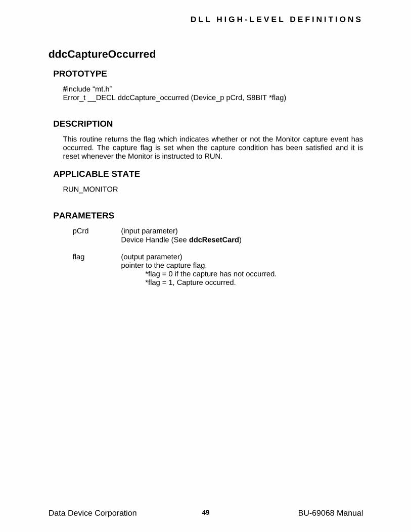
D L L H I G H - L E V E L D E F I N I T I O N S
Data Device Corporation BU-69068 Manual 49
ddcCaptureOccurred
PROTOTYPE
#include ―mt.h‖ Error_t __DECL ddcCapture_occurred (Device_p pCrd, S8BIT *flag)
DESCRIPTION
This routine returns the flag which indicates whether or not the Monitor capture event has occurred. The capture flag is set when the capture condition has been satisfied and it is reset whenever the Monitor is instructed to RUN.
APPLICABLE STATE
RUN_MONITOR
PARAMETERS
pCrd (input parameter)
Device Handle (See ddcResetCard) flag (output parameter) pointer to the capture flag. *flag = 0 if the capture has not occurred. *flag = 1, Capture occurred.
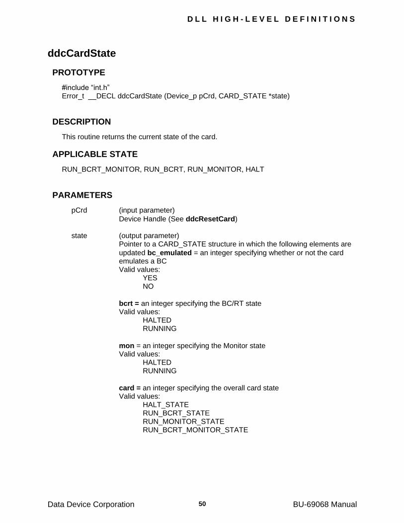
D L L H I G H - L E V E L D E F I N I T I O N S
Data Device Corporation BU-69068 Manual 50
ddcCardState
PROTOTYPE
#include ―int.h‖ Error_t __DECL ddcCardState (Device_p pCrd, CARD_STATE *state)
DESCRIPTION
This routine returns the current state of the card.
APPLICABLE STATE
RUN_BCRT_MONITOR, RUN_BCRT, RUN_MONITOR, HALT
PARAMETERS
pCrd (input parameter)
Device Handle (See ddcResetCard) state (output parameter)
Pointer to a CARD_STATE structure in which the following elements are
updated bc_emulated = an integer specifying whether or not the card emulates a BC
Valid values: YES NO
bcrt = an integer specifying the BC/RT state Valid values: HALTED RUNNING
mon = an integer specifying the Monitor state Valid values: HALTED RUNNING
card = an integer specifying the overall card state Valid values: HALT_STATE RUN_BCRT_STATE RUN_MONITOR_STATE RUN_BCRT_MONITOR_STATE
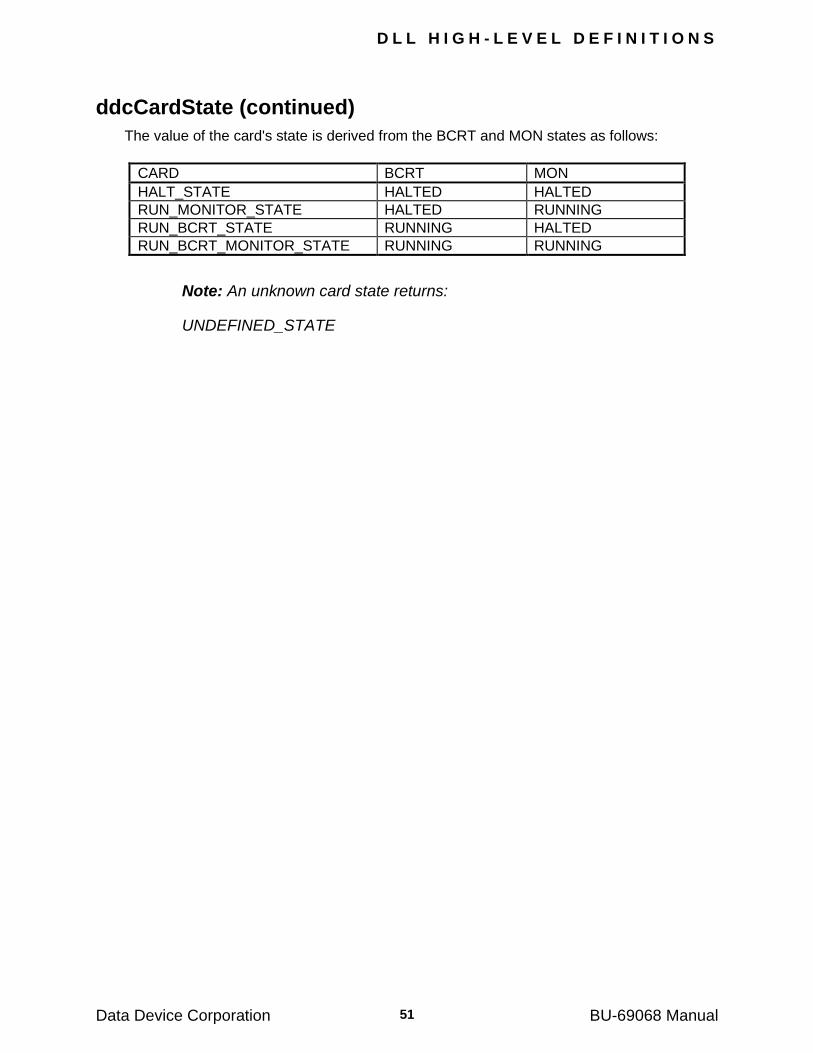
D L L H I G H - L E V E L D E F I N I T I O N S
Data Device Corporation BU-69068 Manual 51
ddcCardState (continued)
The value of the card's state is derived from the BCRT and MON states as follows:
CARD BCRT MON
HALT_STATE HALTED HALTED
RUN_MONITOR_STATE HALTED RUNNING
RUN_BCRT_STATE RUNNING HALTED
RUN_BCRT_MONITOR_STATE RUNNING RUNNING
Note: An unknown card state returns:
UNDEFINED_STATE
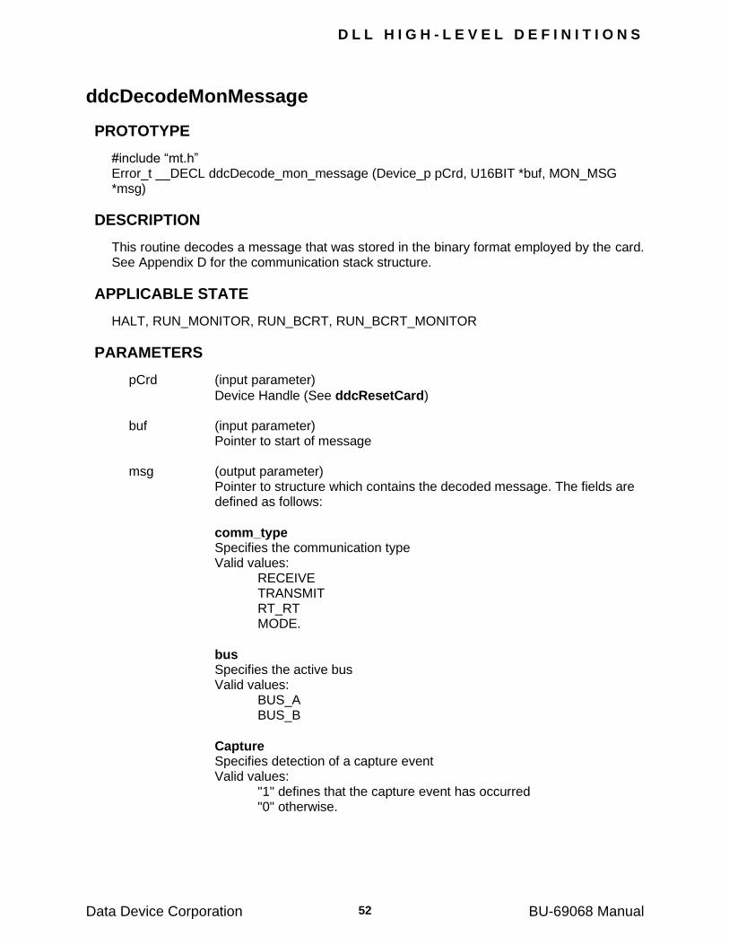
D L L H I G H - L E V E L D E F I N I T I O N S
Data Device Corporation BU-69068 Manual 52
ddcDecodeMonMessage
PROTOTYPE
#include ―mt.h‖ Error_t __DECL ddcDecode_mon_message (Device_p pCrd, U16BIT *buf, MON_MSG *msg)
DESCRIPTION
This routine decodes a message that was stored in the binary format employed by the card. See Appendix D for the communication stack structure.
APPLICABLE STATE
HALT, RUN_MONITOR, RUN_BCRT, RUN_BCRT_MONITOR
PARAMETERS
pCrd (input parameter)
Device Handle (See ddcResetCard) buf (input parameter) Pointer to start of message msg (output parameter)
Pointer to structure which contains the decoded message. The fields are defined as follows:
comm_type Specifies the communication type Valid values: RECEIVE TRANSMIT RT_RT MODE.
bus Specifies the active bus Valid values: BUS_A BUS_B
Capture Specifies detection of a capture event Valid values: "1" defines that the capture event has occurred "0" otherwise.
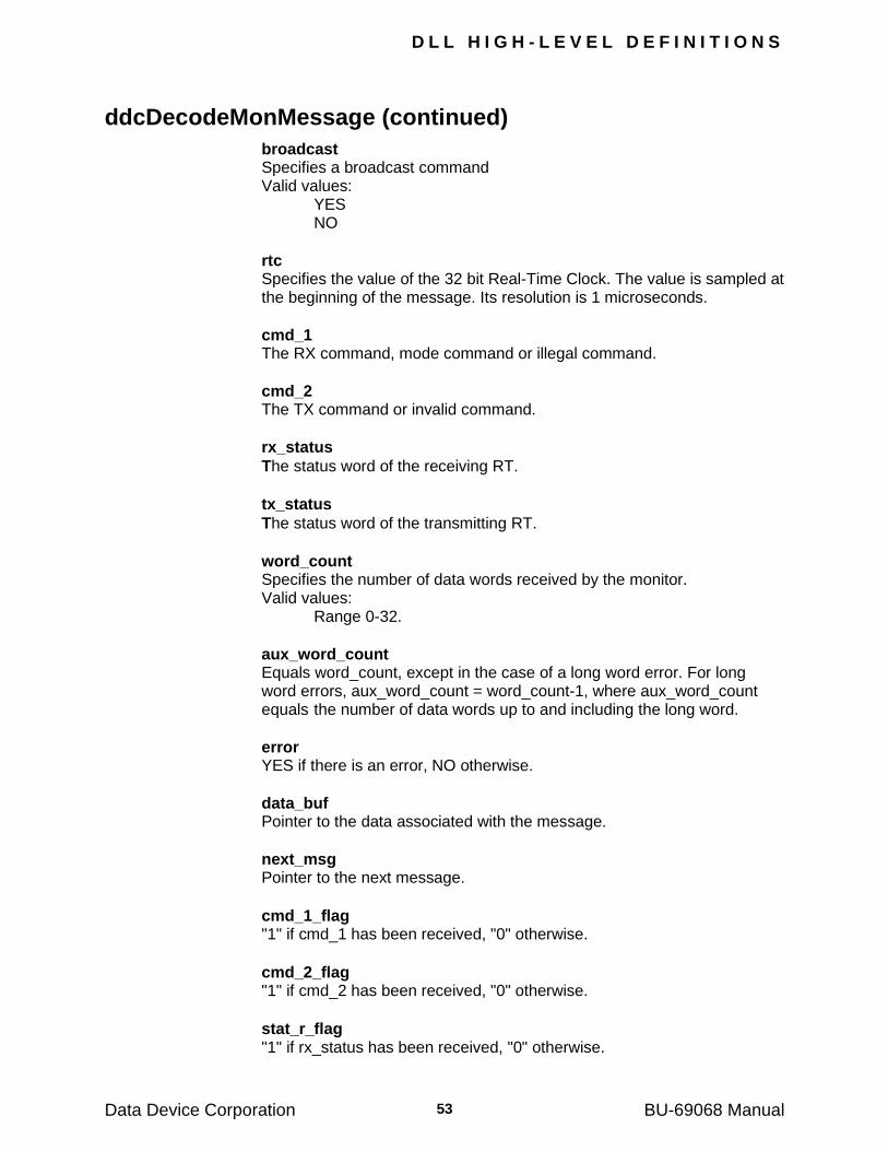
D L L H I G H - L E V E L D E F I N I T I O N S
Data Device Corporation BU-69068 Manual 53
ddcDecodeMonMessage (continued)
broadcast Specifies a broadcast command Valid values: YES NO
rtc Specifies the value of the 32 bit Real-Time Clock. The value is sampled at the beginning of the message. Its resolution is 1 microseconds.
cmd_1 The RX command, mode command or illegal command.
cmd_2 The TX command or invalid command.
rx_status
The status word of the receiving RT.
tx_status
The status word of the transmitting RT.
word_count Specifies the number of data words received by the monitor. Valid values: Range 0-32.
aux_word_count Equals word_count, except in the case of a long word error. For long word errors, aux_word_count = word_count-1, where aux_word_count equals the number of data words up to and including the long word.
error YES if there is an error, NO otherwise.
data_buf Pointer to the data associated with the message.
next_msg Pointer to the next message.
cmd_1_flag "1" if cmd_1 has been received, "0" otherwise.
cmd_2_flag "1" if cmd_2 has been received, "0" otherwise.
stat_r_flag "1" if rx_status has been received, "0" otherwise.
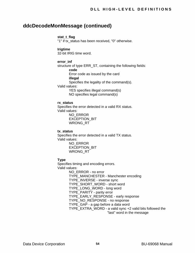
D L L H I G H - L E V E L D E F I N I T I O N S
Data Device Corporation BU-69068 Manual 54
ddcDecodeMonMessage (continued)
stat_t_flag "1" if tx_status has been received, "0" otherwise.
Irigtime 32-bit IRIG time word.
error_inf structure of type ERR_ST, containing the following fields:
code Error code as issued by the card
illegal Specifies the legality of the command(s). Valid values: YES specifies illegal command(s) NO specifies legal command(s)
rx_status Specifies the error detected in a valid RX status. Valid values: NO_ERROR EXCEPTION_BIT WRONG_RT
tx_status Specifies the error detected in a valid TX status. Valid values: NO_ERROR EXCEPTION_BIT WRONG_RT
Type Specifies timing and encoding errors. Valid values: NO_ERROR - no error TYPE_MANCHESTER - Manchester encoding TYPE_INVERSE - inverse sync TYPE_SHORT_WORD - short word TYPE_LONG_WORD - long word TYPE_PARITY - parity error TYPE_EARLY_RESPONSE - early response TYPE_NO_RESPONSE - no response TYPE_GAP - a gap before a data word TYPE_EXTRA_WORD - a valid sync +2 valid bits followed the
"last" word in the message
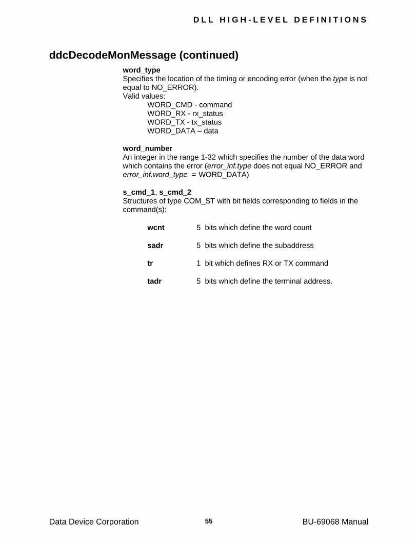
D L L H I G H - L E V E L D E F I N I T I O N S
Data Device Corporation BU-69068 Manual 55
ddcDecodeMonMessage (continued)
word_type Specifies the location of the timing or encoding error (when the type is not
equal to NO_ERROR). Valid values: WORD_CMD - command WORD_RX - rx_status WORD_TX - tx_status WORD_DATA – data
word_number An integer in the range 1-32 which specifies the number of the data word
which contains the error (error_inf.type does not equal NO_ERROR and error_inf.word_type = WORD_DATA)
s_cmd_1, s_cmd_2 Structures of type COM_ST with bit fields corresponding to fields in the
command(s):
wcnt 5 bits which define the word count
sadr 5 bits which define the subaddress
tr 1 bit which defines RX or TX command
tadr 5 bits which define the terminal address.
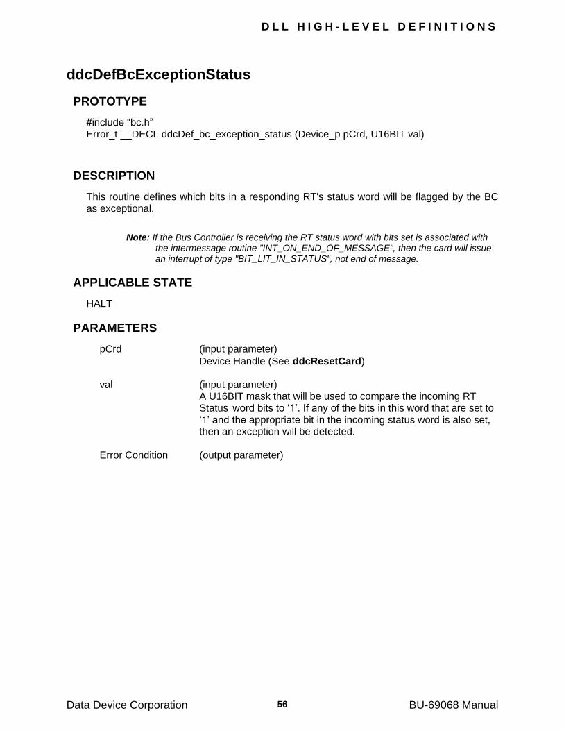
D L L H I G H - L E V E L D E F I N I T I O N S
Data Device Corporation BU-69068 Manual 56
ddcDefBcExceptionStatus
PROTOTYPE
#include ―bc.h‖ Error_t __DECL ddcDef_bc_exception_status (Device_p pCrd, U16BIT val)
DESCRIPTION
This routine defines which bits in a responding RT's status word will be flagged by the BC as exceptional.
Note: If the Bus Controller is receiving the RT status word with bits set is associated with the intermessage routine "INT_ON_END_OF_MESSAGE", then the card will issue an interrupt of type "BIT_LIT_IN_STATUS", not end of message.
APPLICABLE STATE
HALT
PARAMETERS
pCrd (input parameter)
Device Handle (See ddcResetCard) val (input parameter)
A U16BIT mask that will be used to compare the incoming RT Status word bits to ‗1‘. If any of the bits in this word that are set to ‗1‘ and the appropriate bit in the incoming status word is also set, then an exception will be detected.
Error Condition (output parameter)
D L L H I G H - L E V E L D E F I N I T I O N S
Data Device Corporation BU-69068 Manual 57
ddcDefDataBuffering
PROTOTYPE
#include ―bc.h‖ Error_t __DECL ddcDef_data_buffering (Device_p pCrd, S16BIT type)
DESCRIPTION
This routine specifies whether the data tables are double buffered or not. Double buffering can be used to avoid contention when the user's application and the 1553 bus access data tables asynchronously. If data tables are double-buffered, the host exchanges the table pointers before it reads
data and after it writes data. The routine ddcDefDataBuffering assigns size=0 to data tables 1 to 250 and size=32 to tables 0 and 251. In addition, it allocates memory by assigning appropriate values to the data table pointers. As a result, if the user has
previously defined data table sizes, they must be redefined after calling ddcDefTableSize.
Note: The FRAME is assigned size=0 and should also be redefined.
APPLICABLE STATE
HALT
PARAMETERS
pCrd (input parameter)
Device Handle (See ddcResetCard) type (input parameter) Specify the type of data buffering that should be used by the card. Valid values: SINGLE DOUBLE Error Condition (output parameter)
D L L H I G H - L E V E L D E F I N I T I O N S
Data Device Corporation BU-69068 Manual 58
ddcDefEmulateBc
PROTOTYPE
#include ―bc.h‖ Error_t __DECL ddcDef_emulate_bc (Device_p pCrd, S16BIT tadr, S16BIT emulate)
DESCRIPTION
This routine specifies whether or not a BC is emulated and assigns a terminal address to the emulated BC (the BC requires a terminal address since it may pass control and become a RT).
Note: A call to ddcRunBc will override this function, assuming emulate is set to no.
APPLICABLE STATE
HALT
PARAMETERS
pCrd (input parameter)
Device Handle (See ddcResetCard) tadr (input parameter)
An integer in the range 0-30 which defines the terminal address of the BC
emulate (input parameter) Specify whether BC should be emulated Valid values: YES NO Error Condition (output parameter)
D L L H I G H - L E V E L D E F I N I T I O N S
Data Device Corporation BU-69068 Manual 59
ddcDefEmulateRt
PROTOTYPE
#include ―rt.h‖ Error_t __DECL ddcDef_emulate_rt (Device_p pCrd, S16BIT tadr, S16BIT emulate)
DESCRIPTION
This routine defines whether or not an RT with a given terminal address should be emulated.
APPLICABLE STATE
HALT
PARAMETERS
pCrd (input parameter)
Device Handle (See ddcResetCard) tadr (input parameter)
A S16BIT value in the range 0-30 which defines the terminal address.
emulate (input parameter) A S16BIT value that specifies that the RT‘s should be emulated. Valid values: YES NO Error Condition (output parameter)
D L L H I G H - L E V E L D E F I N I T I O N S
Data Device Corporation BU-69068 Manual 60
ddcDefFrame
PROTOTYPE
#include ―bc.h‖ Error_t __DECL ddcDef_frame (Device_p pCrd, S16BIT length, U16BIT *frame)
DESCRIPTION
This routine defines a FRAME, which specifies the contents and timing of a complete communication cycle of the BC. Each entry in the FRAME is either a message number (1-
1023) or a special symbol (see ddcDefMessage for details). The FRAME is divided into minor frames of equal duration. The end of a minor frame is specified by the symbol END_OF_MINOR_FRAME . When the BC encounters this symbol, it waits until the minor frame time has expired before proceeding to the next message. The
minor frame time is defined by the routine ddcDefMinorFrameTime. The end of the FRAME is specified by the symbol END_OF_MAJOR_FRAME. The FRAME can be run one or more times and the total time will be the time for each frame times the number of times the frame is completed.
APPLICABLE STATE
HALT
PARAMETERS
pCrd (input parameter)
Device Handle (See ddcResetCard) length (input parameter)
A S16BIT which defines the number of bytes in the frame. This must be between 1 and 1023
frame (input parameter)
A U16BIT array that defines a sequence of message numbers. Each entry is a U16BIT that corresponds to a message (1-1024), or a special symbol (SKIP, BREAK_POINT, END_OF_MINOR_FRAME, END_OF_MAJOR_FRAME).
See ddcDefMessage for details.
Note: The symbol, END_OF_MAJOR_FRAME, must appear in the frame at least once. After "ddcRunBc" is issued, the card will execute the messages from the frame index specified in ddcRunBc until the first occurrence of END_OF_MAJOR_FRAME. All the messages contained in the frame as well as the minor frame time must be defined ( "ddcDefMessage" and "ddcDefMinorFrameTime") before calling "ddcDefFrame". Messages appearing after the END_OF_MAJOR_FRAME symbol can be referred to by the routine "ddcInsertMessage".
Error Condition (output parameter)
D L L H I G H - L E V E L D E F I N I T I O N S
Data Device Corporation BU-69068 Manual 61
ddcDefFrameTime
PROTOTYPE
#include ―bc.h‖ Error_t __DECL ddcDef_frame_time (Device_p pCrd, S16BIT length, U16BIT *frame, U32BIT *frame_time)
DESCRIPTION
This routine defines a FRAME, which specifies the contents and timing of a complete communication cycle by the BC. Each entry in the FRAME is either a message number (1-1023) or a special symbol. The FRAME is divided into minor frames of equal duration. Each message in the minor
frame is executed after a delay of frame_time from the beginning of the minor frame. The end of a minor frame is specified by the symbol END_OF_MINOR_FRAME. When the BC encounters this symbol, it waits until the minor frame time has expired before proceeding to
the next message. The minor frame time is defined by the routine ddcDefFrameTime. The end of the FRAME is specified by the symbol END_OF_MAJOR_FRAME. The FRAME can be run one or more times. The total time will be computed as the time for each frame, times the number of times the frame is completed.
This routine can be used instead of ddcDefFrame; the only difference is that this routine allows the user to define the timing of BC messages.
APPLICABLE STATE
HALT
PARAMETERS
pCrd (input parameter)
Device Handle (See ddcResetCard) length (input parameter) A S16BIT which defines the number of bytes in the frame. This
value must be between 1 and 1023.
frame (input parameter)
A U16BIT array which defines a sequence of message numbers. Each entry is a U16BIT which corresponds to a message (1 -1023), or a special symbol (SKIP, BREAK_POINT, END_OF_MINOR_FRAME, END_OF_MAJOR_FRAME).
See ddcDefMessage for details.
D L L H I G H - L E V E L D E F I N I T I O N S
Data Device Corporation BU-69068 Manual 62
ddcDefFrameTime (continued)
frame_time (input parameter) A U32BIT array that defines a sequence of message times; each
entry is a long integer which specifies the message time in microseconds from the beginning of a minor frame. The BC will issue the message no earlier than the specified time.
Note: The symbol, END_OF_MAJOR_FRAME, must appear in the frame at least once. After "ddcRunBc" is issued, the card will execute the messages from the start index until the first occurrence of END_OF_MAJOR_FRAME. All the messages contained in the frame as well as the minor frame time must be defined (by "ddcDefMessage" and "ddcDefMinorFrameTime") before calling "ddcDefFrameTime". Messages appearing after the END_OF_MAJOR_FRAME symbol can be referred to by the routine "ddcInsertMessage".
Error Condition (output parameter)
D L L H I G H - L E V E L D E F I N I T I O N S
Data Device Corporation BU-69068 Manual 63
ddcDefIntCmdTemplate
PROTOTYPE
#include ―rt.h‖ Error_t __DECL ddcDef_int_cmd_template (Device_p pCrd, U16BITmaskwd, U16BIT cmpwd)
DESCRIPTION
This routine specifies the 1553 commands that will cause an emulated RT to issue an interrupt to the host. Interrupts will be requested whenever the cmpwd = command AND maskwd. The interrupts are issued by intermessage routines.
APPLICABLE STATE
HALT
PARAMETERS
pCrd (input parameter)
Device Handle (See ddcResetCard) maskwd (input parameter) A U16BIT value that defines a 16 bit mask. cmpwd (input parameter)
A U16BIT value that defines a 16 bit value to be compared to command AND maskwd.
Error Condition (output parameter)
D L L H I G H - L E V E L D E F I N I T I O N S
Data Device Corporation BU-69068 Manual 64
ddcDefIntMask
PROTOTYPE
#include ―bc.h‖ Error_t __DECL ddcDef_int_mask (Device_p pCrd, U16BIT maskreg)
DESCRIPTION
This routine defines which interrupt requests from the card to the host should be masked
(see Section 15.1 for details). ddcDefIntMask affects the BCRT and Monitor modes.
APPLICABLE STATE
HALT
PARAMETERS
Input pCrd (input parameter)
Device Handle (See ddcResetCard) maskreg (input parameter)
A U16BIT value where each bit in this word corresponds to a family of interrupt requests.
Error Condition (output parameter)
D L L H I G H - L E V E L D E F I N I T I O N S
Data Device Corporation BU-69068 Manual 65
ddcDefIntMaskBcrt
PROTOTYPE
#include ―bc.h‖ Error_t __DECL ddcDef_int_mask_bcrt (Device_p pCrd, U16BIT maskreg)
DESCRIPTION
This routine defines which interrupt requests from the card to the host should be masked
(see Section 15.1 for details). ddcDefIntMaskBcrt affects the BCRT mode only.
APPLICABLE STATE
HALT, RUN_MONITOR
PARAMETERS
pCrd (input parameter)
Device Handle (See ddcResetCard) maskreg (input parameter)
A U16BIT value where each bit in this word corresponds to a family of interrupt requests.
Error Condition (output parameter)
D L L H I G H - L E V E L D E F I N I T I O N S
Data Device Corporation BU-69068 Manual 66
ddcDefIntMaskMonitor
PROTOTYPE
#include ―mt.h‖ Error_t __DECL ddcDef_int_mask_monitor (Device_p pCrd U16BIT maskreg)
DESCRIPTION
This routine defines which interrupt requests from the card to the host should be masked
(see Section 15.1 for details). ddcDefIntMaskMonitor affects the Monitor mode only.
APPLICABLE STATE
HALT, RUN_BCRT
PARAMETERS
pCrd (input parameter)
Device Handle (See ddcResetCard) maskreg (input parameter)
A U16BIT value where each bit in this word corresponds to a family of interrupt requests.
Error Condition (output parameter)
D L L H I G H - L E V E L D E F I N I T I O N S
Data Device Corporation BU-69068 Manual 67
ddcDefLastCmd
PROTOTYPES
#include ―rt.h‖ Error_t __DECL ddcDef_last_cmd (Device_p pCrd, S16BIT tadr, U16BIT val)
DESCRIPTION
This routine defines the value of the LAST COMMAND for a specified RT.
APPLICABLE STATE
HALT
PARAMETERS
pCrd (input parameter)
Device Handle (See ddcResetCard) tadr (input parameter)
A S16BIT value in the range 0-30 specifying the terminal address of the RT.
val (input parameter) A U16BIT value specifying the LAST COMMAND Error Condition (output parameter)
D L L H I G H - L E V E L D E F I N I T I O N S
Data Device Corporation BU-69068 Manual 68
ddcDefLastStatus
PROTOTYPE
#include ―rt.h‖ Error_t __DECL ddcDef_last_status (Device_p pCrd, S16BIT tadr, U16BIT val)
DESCRIPTION
This routine defines the value of the LAST STATUS for a specified RT.
APPLICABLE STATE
HALT
PARAMETERS
pCrd (input parameter)
Device Handle (See ddcResetCard) tadr (input parameter)
A S16BIT value in the range 0-30 specifying the terminal address of the RT.
val (input parameter) A U16BIT value specifying the LAST STATUS Error Condition (output parameter)
D L L H I G H - L E V E L D E F I N I T I O N S
Data Device Corporation BU-69068 Manual 69
ddcDefLegalityBcst
PROTOTYPE
#include ―rt.h‖ Error_t __DECL ddcDef_legality_bcst (Device_p pCrd, S16BIT legality)
DESCRIPTION
This routine defines the legality of broadcast commands. Illegal broadcast commands are ignored by RT‘s. By default, broadcast is legal.
APPLICABLE STATE
HALT
PARAMETERS
pCrd (input parameter)
Device Handle (See ddcResetCard) legality (input parameter) A S16BIT value that broadcast is legal. Valid values: LEGAL ILLEGAL Error Condition (output parameter)
D L L H I G H - L E V E L D E F I N I T I O N S
Data Device Corporation BU-69068 Manual 70
ddcDefLegalityDetection
PROTOTYPE
#include ―rt.h‖ Error_t __DECL ddcDef_legality_detection (Device_p pCrd, S16BIT detect)
DESCRIPTION
This routine defines whether or not RT‘s should detect legality. If legality detection is selected, RT‘s will respond to illegal messages with ME=1 in the status and data transmission will be suppressed. By default, illegality is not detected.
APPLICABLE STATE
HALT
PARAMETERS
pCrd (input parameter)
Device Handle (See ddcResetCard) detect (input parameter) A S16BIT value that specifies the legality detection. Valid values: YES NO Error Condition (output parameter)
D L L H I G H - L E V E L D E F I N I T I O N S
Data Device Corporation BU-69068 Manual 71
ddcDefMessage
PROTOTYPE
#include ―bc.h‖ Error_t __DECL ddcDef_message (Device_p pCrd, S16BIT id, struct tagMESSAGE *message)
DESCRIPTION
This routine defines a message for the BC and then loads the result into the card's internal memory. The user must define all fields in the MESSAGE structure that are passed as inputs, except when message ID is assigned the value of a special frame symbol. In this case, the only relevant fields in the following MESSAGE structure are "first and second_intermessage_routine" and "time_to_next_message".
APPLICABLE STATE
HALT
PARAMETERS
pCrd (input parameter)
Device Handle (See ddcResetCard) id (input parameter)
A S16BIT value in the range 1-1023 which specifies a message number or a special frame symbol;
Valid values: 1-1023 - message number except for these values 251 - reserved 252 - SKIP - This symbol causes the next message in the
frame to be skipped; however, the intermessage routines associated with the SKIP are executed. 253 - BREAK_POINT - This symbol causes the BC to halt.
If a ddcRunContinue is subsequently issued, the communication will continue from the next frame symbol.
254 - END_OF_MAJOR_FRAME - Refer to ddcDefFrame for details.
255 - END_OF_MINOR_FRAME - Refer to ddcDefFrame for details.
D L L H I G H - L E V E L D E F I N I T I O N S
Data Device Corporation BU-69068 Manual 72
ddcDefMessage (continued)
message (input parameter) A pointer to a MESSAGE structure which receives the following inputs:
Note: Tables 0 and 251 are illegal tables which cannot be used for a message. If they are used, error 102 ILLEGAL_TABLE_ID will be returned by ddcDef_message().
comm_type: Char defining the type of communication Valid values: RECEIVE TRANSMIT MODE RT_RT NOP
cmd_1: CMD structure defining the command appearing in the message (decimal values for terminal address, T/R, sub-address, word count: see Appendix F).
cmd_2: CMD structure defining the commands appearing in the message (decimal values for terminal address, T/R, sub-address, word count: see Appendix F).
Time_to_next_message: A U16BIT value in the range 1-216 microseconds, which defines the time from the start of the present message to the start of the next message.
Data_table_no: A U16BIT value in the range 1-1023 which defines the data table. This field is taken to be the first data table number to be used for block data.
last_data_table_no: A U16BIT value in the range 1-1023 which is used for the last data table number for block data. If the Intermessage Routine IMR_BLOCK_DATA_BC is assigned to this message, the BC will treat the sequence of tables from data_table_no to last_data_table_no as one block of data. The BC will then cyclically update the number of the data table to be used each time the message is transmitted.
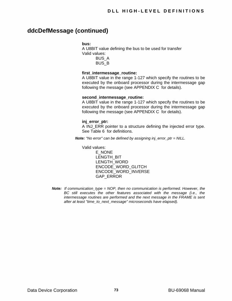
D L L H I G H - L E V E L D E F I N I T I O N S
Data Device Corporation BU-69068 Manual 73
ddcDefMessage (continued)
bus: A U8BIT value defining the bus to be used for transfer Valid values: BUS_A BUS_B
first_intermessage_routine: A U8BIT value in the range 1-127 which specify the routines to be executed by the onboard processor during the intermessage gap following the message (see APPENDIX C for details).
second_intermessage_routine: A U8BIT value in the range 1-127 which specify the routines to be executed by the onboard processor during the intermessage gap following the message (see APPENDIX C for details).
inj_error_ptr: A INJ_ERR pointer to a structure defining the injected error type. See Table 6 for definitions.
Note: "No error" can be defined by assigning inj_error_ptr = NILL.
Valid values: E_NONE LENGTH_BIT LENGTH_WORD ENCODE_WORD_GLITCH ENCODE_WORD_INVERSE GAP_ERROR
Note: If communication_type = NOP, then no communication is performed. However, the BC still executes the other features associated with the message (i.e., the intermessage routines are performed and the next message in the FRAME is sent after at least "time_to_next_message" microseconds have elapsed).
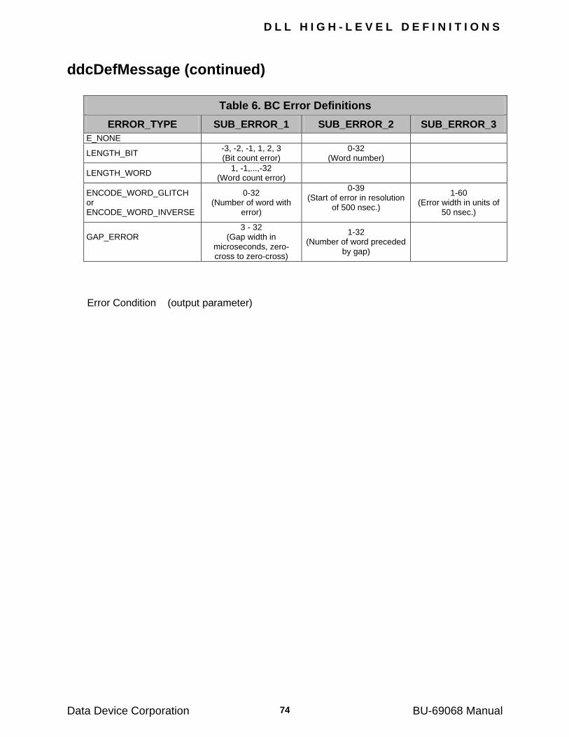
D L L H I G H - L E V E L D E F I N I T I O N S
Data Device Corporation BU-69068 Manual 74
ddcDefMessage (continued)
Table 6. BC Error Definitions
ERROR_TYPE SUB_ERROR_1 SUB_ERROR_2 SUB_ERROR_3
E_NONE
LENGTH_BIT -3, -2, -1, 1, 2, 3 (Bit count error)
0-32 (Word number)
LENGTH_WORD 1, -1,...,-32
(Word count error)
ENCODE_WORD_GLITCH or ENCODE_WORD_INVERSE
0-32 (Number of word with
error)
0-39 (Start of error in resolution
of 500 nsec.)
1-60 (Error width in units of
50 nsec.)
GAP_ERROR
3 - 32 (Gap width in
microseconds, zero-cross to zero-cross)
1-32 (Number of word preceded
by gap)
Error Condition (output parameter)
D L L H I G H - L E V E L D E F I N I T I O N S
Data Device Corporation BU-69068 Manual 75
ddcDefMinorFrameTime
PROTOTYPES
#include ―bc.h‖ Error_t __DECL ddcDef_minor_frame_time (Device_p pCrd, S32BIT val)
DESCRIPTION
This routine specifies the minor frame time for the BC.
APPLICABLE STATE
HALT
PARAMETERS
pCrd (input parameter)
Device Handle (See ddcResetCard) val A S32BIT value in the range 0 to 232-1 (time in microseconds).
This values specifies the total time of the minor frame. Error Condition (output parameter)
D L L H I G H - L E V E L D E F I N I T I O N S
Data Device Corporation BU-69068 Manual 76
ddcDefModeLegality
PROTOTYPE
#include ―rt.h‖ Error_t __DECL ddcDef_mode_legality (Device_p pCrd, S16BIT mode_code, S16BIT legality)
DESCRIPTION
This routine defines the legality of mode commands. The definition is common to all RT‘s. By default, all reserved mode commands as well as "Selected Transmitter Shutdown" and "Override Selected Transmitter Shutdown" are illegal.
APPLICABLE STATE
HALT
PARAMETERS
pCrd (input parameter)
Device Handle (See ddcResetCard) mode_code (input parameter) An integer in the range 0-31 which corresponds to the mode code. legality (input parameter) A S16BIT value that specifies legality of mode commands. Valid values: LEGAL ILLEGAL Error Condition (output parameter)
D L L H I G H - L E V E L D E F I N I T I O N S
Data Device Corporation BU-69068 Manual 77
ddcDefModeRoutine
PROTOTYPE
#include ―rt.h‖ Error_t __DECL ddcDef_mode_routine (Device_p pCrd, S16BIT mode_code, S16BIT im_routine_1, S16BIT im_routine_2
DESCRIPTION
This routine assigns 2 intermessage routines to a mode command. An emulated RT executes these routines immediately after the mode command is executed.
Note: The 2 RT intermessage routines will only be executed if the BC is not emulated (i.e.,
the BC is external to the BU-65570/2i, BU-65570/2T, BU-65570/2v and BU-
65570M). If the BC is emulated, then the intermessage routines associated with the message structure are executed instead.
APPLICABLE STATE
HALT
PARAMETERS
pCrd (input parameter)
Device Handle (See ddcResetCard) mode_code (input parameter) A S16BIT value in the range 0-31 specifying the mode code. im_routine_1 (input parameter)
A S16BIT value in the range 1-127 specifying the first intermessage routine to be executed by the RT.
im_routine_2 (input parameter)
A S16BIT value in the range 1-127 specifying the second intermessage routine to be executed by the RT.
Error Condition (output parameter)
D L L H I G H - L E V E L D E F I N I T I O N S
Data Device Corporation BU-69068 Manual 78
ddcDefMonExceptionStatus
PROTOTYPE
#include ―mt.h‖ Error_t __DECL ddcDef_mon_exception_status (Device_p pCrd, U16BIT val)
DESCRIPTION
This routine defines which bits in a responding RT's status word will be flagged by the Monitor as exceptional.
Note: If the monitor is receiving the RT status word with bits set is associated with the intermessage routine "IMR_INT_ON_END_OF_MESSAGE", then the card will issues an interrupt of type "BIT SET IN STATUS", not end of message.
Note: The error, "BIT SET IN STATUS", which is recorded in the message structure relates only to the ME and BUSY bits.
APPLICABLE STATE
HALT
PARAMETERS
pCrd (input parameter)
Device Handle (See ddcResetCard) val (input parameter)
A U16BIT mask that will be used to compare the incoming RT Status word bits to ‗1‘. If any of the bits in this word are set to ‗1‘ and the appropriate bit in the incoming status word is also set, then an exception will be flagged by the monitor.
Error Condition (output parameter)
D L L H I G H - L E V E L D E F I N I T I O N S
Data Device Corporation BU-69068 Manual 79
ddcDefMonitorStack
PROTOTYPE
#include ―mt.h‖ Error_t __DECL ddcDef_monitor_stack (Device_p pCrd, U16BIT type)
DESCRIPTION
This routine defines whether or not the Monitor's buffer in the card's shared memory is cyclic. Based on the value of the ‗type‘ parameter, the monitor stack can be set up as a single pass queue or a circular buffer that will recycle when the end is reached.
APPLICABLE STATE
HALT
PARAMETERS
pCrd (input parameter)
Device Handle (See ddcResetCard) type (input parameter)
This U16BIT value defines the operation of the monitor stack. Based on the value, the monitor stack will either run to the end and stop receiving new messages from the bus or it will wrap back to the beginning of the stack
Valid values: CYCLIC_STACK NON_CYCLIC_STACK Error Condition (output parameter)
D L L H I G H - L E V E L D E F I N I T I O N S
Data Device Corporation BU-69068 Manual 80
ddcDefRt
PROTOTYPE
#include ―rt.h‖ Error_t __DECL ddcDef_rt (Device_p pCrd, S16BIT tadr, struct _tagRT_DEFS *rt)
DESCRIPTION
This routine defines the operation of an RT. The basic operation of the RT will be specified by the RT terminal address and the data entries of the RT_DEFS structure.
APPLICABLE STATE
HALT
PARAMETERS
Input pCrd (input parameter)
Device Handle (See ddcResetCard) tadr (input parameter)
A S16BIT value in the range 0-30 which defines the RT terminal address.
Note: Terminal address 31 is reserved for broadcast commands.
rt (input parameter)
A pointer to an RT_DEFS structure which defines the RT parameters. The following defines the entries of this structure and the values to which they can be set.
basic_status A S16BIT value OR'd with the communication status
before it is sent by the RT; the most significant 5 bits (terminal address field) do not affect the status.
inj_error A INJ_ERR pointer to a structure consisting of 4 integers:
error_type, sub_error_1, sub_error_2, sub_error_3. The values are given in Table 7.
dbca A S16BIT value that defines the response to the mode
command "Dynamic Bus Control" Valid values:
YES (the RT will set the DBCA bit in the status and accept control)
NO (specifies that the RT will not accept control)
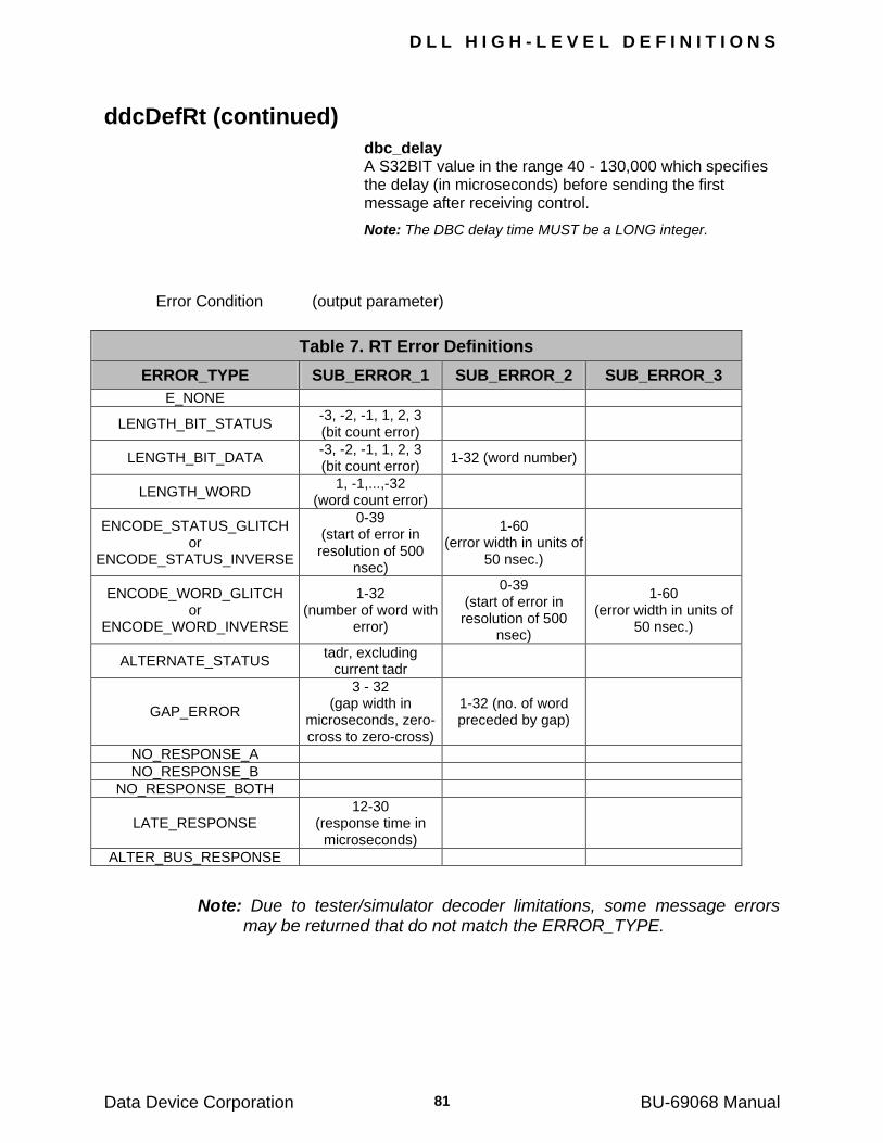
D L L H I G H - L E V E L D E F I N I T I O N S
Data Device Corporation BU-69068 Manual 81
ddcDefRt (continued)
dbc_delay A S32BIT value in the range 40 - 130,000 which specifies the delay (in microseconds) before sending the first message after receiving control.
Note: The DBC delay time MUST be a LONG integer.
Error Condition (output parameter)
Table 7. RT Error Definitions
ERROR_TYPE SUB_ERROR_1 SUB_ERROR_2 SUB_ERROR_3
E_NONE
LENGTH_BIT_STATUS -3, -2, -1, 1, 2, 3 (bit count error)
LENGTH_BIT_DATA -3, -2, -1, 1, 2, 3 (bit count error)
1-32 (word number)
LENGTH_WORD 1, -1,...,-32
(word count error)
ENCODE_STATUS_GLITCH or
ENCODE_STATUS_INVERSE
0-39 (start of error in resolution of 500
nsec)
1-60 (error width in units of
50 nsec.)
ENCODE_WORD_GLITCH or
ENCODE_WORD_INVERSE
1-32 (number of word with
error)
0-39 (start of error in resolution of 500
nsec)
1-60 (error width in units of
50 nsec.)
ALTERNATE_STATUS tadr, excluding
current tadr
GAP_ERROR
3 - 32 (gap width in
microseconds, zero-cross to zero-cross)
1-32 (no. of word preceded by gap)
NO_RESPONSE_A
NO_RESPONSE_B
NO_RESPONSE_BOTH
LATE_RESPONSE 12-30
(response time in microseconds)
ALTER_BUS_RESPONSE
Note: Due to tester/simulator decoder limitations, some message errors may be returned that do not match the ERROR_TYPE.
D L L H I G H - L E V E L D E F I N I T I O N S
Data Device Corporation BU-69068 Manual 82
ddcDefRtMap
PROTOTYPE
#include ―rt.h‖ Error_t __DECL ddcDef_rt_map (Device_p pCrd, S16BIT tadr, S16BIT tr_bit, S16BIT sadr, S16BIT table_id)
DESCRIPTION
This routine determines which data tables should be used by a given RT when responding to the given receive/transmit command. Data tables will be attached to a RT based on RT terminal address, the transmit/receive bit and the Sub-address. A table may also be attached to any number of RT‘s, T/R‘s and Sub-addresses. This function will have to be run each time a data table is mapped to a RT.
APPLICABLE STATE
HALT
PARAMETERS
pCrd (input parameter)
Logical Device Handle (See ddcResetCard) tadr (input parameter)
A S16BIT value in the range 0-31 specifying the terminal address of the RT
tr_bit (input parameter)
A S16BIT value that determines whether the message is a transmit or receive.
Valid values: RECEIVE TRANSMIT sadr (input parameter) A S16BIT value in the range 1-30 specifying the sub-address. table_id (input parameter)
A S16BIT value in the range 1-1023 specifying the data table number. The value of this parameter must be greater than or equal to first_table_id.
Note: By default all receive/transmit commands are illegal (i.e., receive commands are mapped to rxillegal (data table 0) and transmit commands to txillegal (data table 251).
Error Condition (output parameter)
D L L H I G H - L E V E L D E F I N I T I O N S
Data Device Corporation BU-69068 Manual 83
ddcDefRtMapBlock
PROTOTYPE
#include ―rt.h‖ Error_t __DECL ddcDef_rt_map_block (Device_p pCrd, S16BIT tadr, S16BIT tr_bit, S16BIT sadr, S16BIT start_table_id, S16BIT end_table_id)
DESCRIPTION
This routine determines which contiguous block of data tables should be used by a given RT when responding to the given receive/transmit command. It assigns a sequence of data tables from the first_table to the last_table for the given RT when responding to the given receive/transmit command. In order for the block to be implemented, the Intermessage Routine, IMR_BLOCK_DATA_RT, must be assigned to each of the data tables.
APPLICABLE STATE
HALT
PARAMETERS
pCrd (input parameter)
Device Handle (See ddcResetCard) tadr (input parameter)
A S16BIT value in the range 0-31 specifying the terminal address of the RT
tr_bit (input parameter)
A S16BIT value that determines whether the message is a transmit or receive.
Valid values: RECEIVE TRANSMIT sadr (input parameter) A S16BIT value in the range 1-30 specifying the sub-address. start_table_id (input parameter)
A S16BIT value in the range 1-1023 specifying the first data table number
D L L H I G H - L E V E L D E F I N I T I O N S
Data Device Corporation BU-69068 Manual 84
ddcDefRtMapBlock (continued)
end_table_id (input parameter) A S16BIT value in the range (Start_table_id+1)-1023 specifying
the last_data table number. It must be greater than or equal to first_table_id.
Note: By default all receive/transmit commands are illegal (i.e., receive commands are mapped to table 0 and transmit commands to table 255).
Error Condition (output parameter)
D L L H I G H - L E V E L D E F I N I T I O N S
Data Device Corporation BU-69068 Manual 85
ddcDefTableRoutine
PROTOTYPE
#include ―rt.h‖ Error_t __DECL ddcDef_table_routine (Device_p pCrd, S16BIT id, S16BIT im_routine_1,S16BIT im_routine_2)
DESCRIPTION
This routine assigns 2 intermessage routines to a data table. An emulated RT executes these routines immediately after processing the message that caused it to access the data table.
APPLICABLE STATE
HALT
PARAMETERS
pCrd (input parameter)
Device Handle (See ddcResetCard) id (input parameter) A S16BIT in the range 0-1023 which identifies the data table. im_routine_1 (input parameter)
A S16BIT in the range 1-127 which specifies a routine to be executed by the RT. Refer to APPENDIX C.
im_routine_2 (input parameter)
A S16BIT in the range 1-127 which specifies a routine to be executed by the RT. Refer to APPENDIX C.
Error Condition (output parameter)
D L L H I G H - L E V E L D E F I N I T I O N S
Data Device Corporation BU-69068 Manual 86
ddcDefTableSize
PROTOTYPE
#include ―bc.h‖ Error_t __DECL ddcDef_table_size (Device_p pCrd, S16BIT id, S16BIT size)
DESCRIPTION
This routine defines the number of words in a data table. The total amount of memory
allocated to all the data tables is limited by the available memory of the BU-65570/2i, BU-
65570/2v and BU-65570M, which has a maximum of 64K words available for all data tables
and message entries. The BU-65570/2T has a maximum of 12K words.
Note: If the size of a data table is changed, then all pointers to subsequent tables (i.e., those with a larger identification number) are also changed. Since data is not moved after the pointers are adjusted, the contents of the tables must be redefined.
APPLICABLE STATE
HALT
PARAMETERS
pCrd (input parameter)
Device Handle (See ddcResetCard) id (input parameter) A S16BIT in the range 0-1023 which identifies the table. size (input parameter)
A S16BIT in the range 0-32 which specifies the number of words in the table (0 specifies that the table is not used); the size for tables 0 and 251 is fixed to 32 words (the user should not change it), all other tables are assigned size 0.
Error Condition (output parameter)

D L L H I G H - L E V E L D E F I N I T I O N S
Data Device Corporation BU-69068 Manual 87
ddcDeselectAllMessages
PARAMETER
#include ―mt.h‖ Error_t __DECL ddcDeselect_all_messages (Device_p pCrd, U16BIT tadr)
DESCRIPTION
This routine specifies that all messages to a given RT shall be deselected by the Monitor (by default all messages are selected).
APPLICABLE STATE
HALT
PARAMETERS
pCrd (input parameter)
Device Handle (See ddcResetCard) tadr (input parameter) A U16BIT value in the range 0-31 which specifies the RT address. Error Condition (output parameter)
D L L H I G H - L E V E L D E F I N I T I O N S
Data Device Corporation BU-69068 Manual 88
ddcDeselectMessage
PROTOTYPE
#include ―mt.h‖ Error_t __DECL ddcDeselect_message ( Device_p pCrd, U16BIT tadr, U16BIT tr, U16BIT sadr)
DESCRIPTION
This routine specifies the messages to be deselected by the Monitor. The decision is based on the values of RT address, T/R bit and sub-address.
APPLICABLE STATE
HALT
PARAMETERS
pCrd (input parameter)
Device Handle (See ddcResetCard) tadr (input parameter) A U16BIT value in the range 0-31 which specifies the RT address. tr (input parameter) A U16BIT value that specifies the direction of the message. Valid values: TRANSMIT RECEIVE sadr (input parameter)
A U16BIT value in the range 0-31 which specifies the sub-address.
Note: Mode commands are selected by specifying sadr = 0 or 31
Error Condition (output parameter)
D L L H I G H - L E V E L D E F I N I T I O N S
Data Device Corporation BU-69068 Manual 89
ddcDisableDma
PROTOTYPE
#include ―mt.h‖ Error_t __DECL ddcDisableDma(Device_p pCrd)
DESCRIPTION
This function is used to disable DMA operation for the specified Device. Once DMA operations have been disabled, the host buffer that was created for use with DMA will be discarded. All data that resides in the DMA buffer will be destroyed, and should not be accessed.
APPLICABLE STATE
HALT
PARAMETERS
pCrd (input parameter)
Device Handle (See ddcResetCard) Error Condition (output parameter)
D L L H I G H - L E V E L D E F I N I T I O N S
Data Device Corporation BU-69068 Manual 90
ddcEnableDma
PROTOTYPE
#include ―mt.h‖ Error_t __DECL ddcEnableDma (Device_p pCrd, U32BIT dwSize)
DESCRIPTION
This routine is used to enable DMA operation while in the monitor mode.
Note: Presently this is only available for monitor operations, but may be added to RT and BC operations in the future. This routine is used to enable the DMA transfer of data from the Monitor circular buffers to a host buffer. The host buffer size is defined in BYTES using the second parameter.
The DMA buffer has a minimum value of 64K. The maximum value must be able to fit within the system‘s memory. If and incorrect size is specified, the function will return an error.
Note: This mode is not available for the BU-65570M PCMCIA card.
APPLICABLE STATE
HALT
PARAMETERS
pCrd (input parameter)
Device Handle (See ddcResetCard) dwSize (input parameter)
A U32BIT value specifying the size of the DMA buffer to be created and enabled in the host computer.
Valid values: Must be greater than 64K Must be able to fit in the system memory. Error Condition (output parameter)
D L L H I G H - L E V E L D E F I N I T I O N S
Data Device Corporation BU-69068 Manual 91
ddcEnableIrig
PROTOTYPE
#include ―mt.h‖ Error_t __DECL ddcEnableIrig(Device_p pCrd, U16BIT Enable)
DESCRIPTION
This function is used to enable or disable IRIG time on the card.
Note: To get complete IRIG time an external IRIG clock is needed.
APPLICABLE STATE
HALT
PARAMETERS
pCrd (input parameter)
Device Handle (See ddcResetCard) Enable (input parameter)
A U16BIT value that is either TRUE to enable the IRIG time or FALSE to disable IRIG.
Error Condition (output parameter)
D L L H I G H - L E V E L D E F I N I T I O N S
Data Device Corporation BU-69068 Manual 92
ddcFlushDmaBuffer
PROTOTYPE
#include ―mt.h‖ Error_t __DECL ddcFlushDmaBuffer(Device_p pCrd)
DESCRIPTION
This function is used to flush all of the data that is presently stored in the DMA buffer.
APPLICABLE STATE
HALT
PARAMETERS
pCrd (input parameter)
Device Handle (See ddcResetCard) Error Condition (output parameter)
D L L H I G H - L E V E L D E F I N I T I O N S
Data Device Corporation BU-69068 Manual 93
ddcGetBcDataTable
PROTOTYPE
#include ―bc.h‖ Error_t __DECL ddcGet_bc_data_table (Device_p pCrd, S16BIT message_id, S16BIT t_r, S16BIT *data_table_number)
DESCRIPTION
This routine returns the data table number last used by the BC for the specified receive/transmit message. This is useful when using the BLOCK_DATA feature for the BC, since the BC can be cyclically running through a set of data tables.
APPLICABLE STATE
HALT
PARAMETERS
pCrd (input parameter)
Device Handle (See ddcResetCard) message_id (input parameter)
A S16BIT value in the range 1-1023 that specifies a message number.
t_r (input parameter) A S16BIT value defining the type of command in the message Valid values: RECEIVE TRANSMIT data_table_number (output parameter)
Address of a S16BIT value that will contain the return value of the data table number that was last accessed by the BC for the specified message.
D L L H I G H - L E V E L D E F I N I T I O N S
Data Device Corporation BU-69068 Manual 94
ddcGetBcHaltParameters
PROTOTYPE
#include ―bc.h‖ Error_t __DECL ddcGet_bc_halt_parameters (Device_p pCrd, S32BIT *rem_times, S16BIT *frame_pos, S16BIT *bc_tadr)
DESCRIPTION
This routine reads the BC parameters after the BC transitions to the HALT state.
APPLICABLE STATE
HALT
PARAMETERS
pCrd (input parameter)
Device Handle (See ddcResetCard) rem_times (output parameter)
Address of a S32BIT pointer to the remaining number of times to execute the frame.
frame_pos (output parameter)
Address of a S16BIT pointer to the message position of the BC in the frame.
bc_tadr (output parameter)
Address of a S16BIT pointer to the terminal address of the current BC. If the BC is not emulated, the value by default is ‗0‘ and the operation is ‗Off‖.
D L L H I G H - L E V E L D E F I N I T I O N S
Data Device Corporation BU-69068 Manual 95
ddcGetErrorMessage
PROTOTYPE
#include ―err.h‖ Error_t __DECL ddcGetErrorMessage(Device_p pCrd, Error_t error_number, char *error_string)
DESCRIPTION
This function is used to obtain the RTL error string for the corresponding error number.
APPLICABLE STATE
HALT, RUN_BCRT_MONITOR, RUN_MONITOR, RUN_BCRT
PARAMETERS
pCrd (input parameter)
Device Handle (See ddcResetCard) error_number (input parameter) Error code that is returned by a RTL function error_string (output parameter)
Buffer which receives the error string for the corresponding error number.
D L L H I G H - L E V E L D E F I N I T I O N S
Data Device Corporation BU-69068 Manual 96
ddcGetGlueLogicVersion
PROTOTYPE
#include ―int.h‖ Error_t __DECL ddcGetGlueLogicVersion(Device_p pCrd, U16BIT *gl_ver)
DESCRIPTION
This function is used to get the version number for FPGA Glue Logic.
Note: The glue logic version for the BU-65570M card is 0.
APPLICABLE STATE
HALT, RUN_BCRT_MONITOR, RUN_MONITOR, RUN_BCRT
PARAMETERS
pCrd (input parameter)
Device Handle (See ddcResetCard) gl_ver (output parameter)
Returns the glue logic version of the card.
D L L H I G H - L E V E L D E F I N I T I O N S
Data Device Corporation BU-69068 Manual 97
ddcGetMTCounters
PROTOTYPE
#include ―mt.h‖ Error_t __DECL ddcGetMTCounters(Device_p pCrd, U32BIT *invalid, U32BIT *total, U16BIT *buff)
DESCRIPTION
This routine is used by the Tester/Simulator Menu (BU-69065) to display the activity on the bus while the card is running.
APPLICABLE STATE
HALT, RUN_BCRT_MONITOR, RUN_MONITOR, RUN_BCRT
PARAMETERS
pCrd (input parameter)
Device Handle (See ddcResetCard) invalid (output parameter)
A U32BIT pointer that specifies the location of the total number of invalid messages that have been sent across the bus.
total (output parameter)
A U32BIT pointer that specifies the location of the total number of messages that have been sent across the bus.
buff (output parameter) A U16BIT pointer that specifies the location of the copy of the stack.
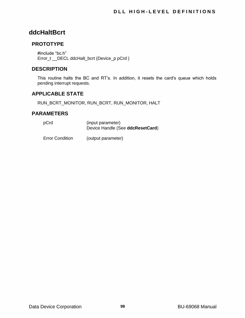
D L L H I G H - L E V E L D E F I N I T I O N S
Data Device Corporation BU-69068 Manual 98
ddcHaltBcrt
PROTOTYPE
#include ―bc.h‖ Error_t __DECL ddcHalt_bcrt (Device_p pCrd )
DESCRIPTION
This routine halts the BC and RT‘s. In addition, it resets the card's queue which holds pending interrupt requests.
APPLICABLE STATE
RUN_BCRT_MONITOR, RUN_BCRT, RUN_MONITOR, HALT
PARAMETERS
pCrd (input parameter)
Device Handle (See ddcResetCard) Error Condition (output parameter)
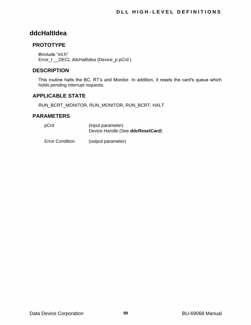
D L L H I G H - L E V E L D E F I N I T I O N S
Data Device Corporation BU-69068 Manual 99
ddcHaltIdea
PROTOTYPE
#include ―int.h‖ Error_t __DECL ddcHaltIdea (Device_p pCrd )
DESCRIPTION
This routine halts the BC, RT‘s and Monitor. In addition, it resets the card's queue which holds pending interrupt requests.
APPLICABLE STATE
RUN_BCRT_MONITOR, RUN_MONITOR, RUN_BCRT, HALT
PARAMETERS
pCrd (input parameter)
Device Handle (See ddcResetCard) Error Condition (output parameter)
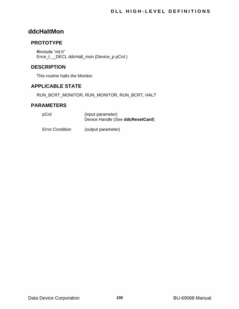
D L L H I G H - L E V E L D E F I N I T I O N S
Data Device Corporation BU-69068 Manual 100
ddcHaltMon
PROTOTYPE
#include ―mt.h‖ Error_t __DECL ddcHalt_mon (Device_p pCrd )
DESCRIPTION
This routine halts the Monitor.
APPLICABLE STATE
RUN_BCRT_MONITOR, RUN_MONITOR, RUN_BCRT, HALT
PARAMETERS
pCrd (input parameter)
Device Handle (See ddcResetCard) Error Condition (output parameter)
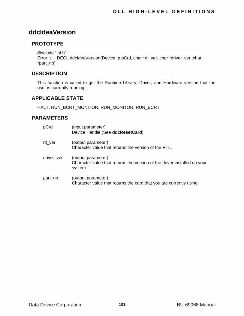
D L L H I G H - L E V E L D E F I N I T I O N S
Data Device Corporation BU-69068 Manual 101
ddcIdeaVersion
PROTOTYPE
#include ―int.h‖ Error_t __DECL ddcIdeaVersion(Device_p pCrd, char *rtl_ver, char *driver_ver ,char *part_no)
DESCRIPTION
This function is called to get the Runtime Library, Driver, and Hardware version that the user is currently running.
APPLICABLE STATE
HALT, RUN_BCRT_MONITOR, RUN_MONITOR, RUN_BCRT
PARAMETERS
pCrd (input parameter)
Device Handle (See ddcResetCard) rtl_ver (output parameter) Character value that returns the version of the RTL. driver_ver (output parameter)
Character value that returns the version of the driver installed on your system.
part_no (output parameter) Character value that returns the card that you are currently using.
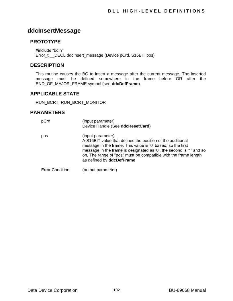
D L L H I G H - L E V E L D E F I N I T I O N S
Data Device Corporation BU-69068 Manual 102
ddcInsertMessage
PROTOTYPE
#include ―bc.h‖ Error_t __DECL ddcInsert_message (Device pCrd, S16BIT pos)
DESCRIPTION
This routine causes the BC to insert a message after the current message. The inserted message must be defined somewhere in the frame before OR after the
END_OF_MAJOR_FRAME symbol (see ddcDefFrame).
APPLICABLE STATE
RUN_BCRT, RUN_BCRT_MONITOR
PARAMETERS
pCrd (input parameter)
Device Handle (See ddcResetCard) pos (input parameter)
A S16BIT value that defines the position of the additional message in the frame. This value is ‗0‘ based, so the first message in the frame is designated as ‗0‘, the second is ‗1‘ and so on. The range of "pos" must be compatible with the frame length
as defined by ddcDefFrame Error Condition (output parameter)
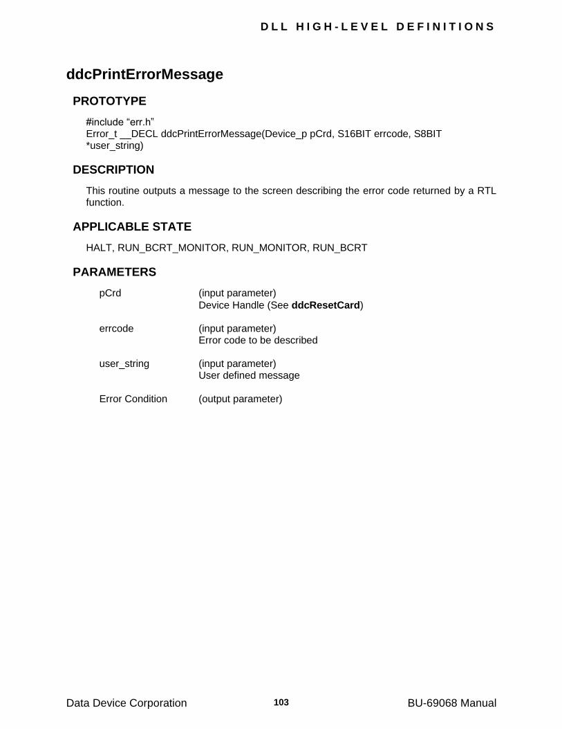
D L L H I G H - L E V E L D E F I N I T I O N S
Data Device Corporation BU-69068 Manual 103
ddcPrintErrorMessage
PROTOTYPE
#include ―err.h‖ Error_t __DECL ddcPrintErrorMessage(Device_p pCrd, S16BIT errcode, S8BIT *user_string)
DESCRIPTION
This routine outputs a message to the screen describing the error code returned by a RTL function.
APPLICABLE STATE
HALT, RUN_BCRT_MONITOR, RUN_MONITOR, RUN_BCRT
PARAMETERS
pCrd (input parameter)
Device Handle (See ddcResetCard) errcode (input parameter) Error code to be described user_string (input parameter) User defined message Error Condition (output parameter)
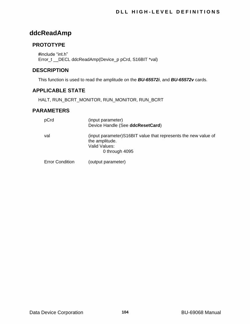
D L L H I G H - L E V E L D E F I N I T I O N S
Data Device Corporation BU-69068 Manual 104
ddcReadAmp
PROTOTYPE
#include ―int.h‖ Error_t __DECL ddcReadAmp(Device_p pCrd, S16BIT *val)
DESCRIPTION
This function is used to read the amplitude on the BU-65572i, and BU-65572v cards.
APPLICABLE STATE
HALT, RUN_BCRT_MONITOR, RUN_MONITOR, RUN_BCRT
PARAMETERS
pCrd (input parameter)
Device Handle (See ddcResetCard) val (input parameter)S16BIT value that represents the new value of
the amplitude. Valid Values: 0 through 4095 Error Condition (output parameter)
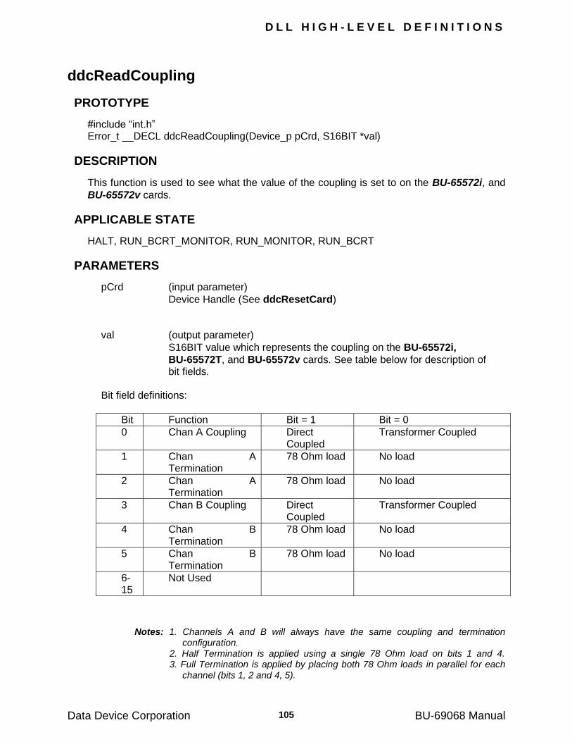
D L L H I G H - L E V E L D E F I N I T I O N S
Data Device Corporation BU-69068 Manual 105
ddcReadCoupling
PROTOTYPE
#include ―int.h‖ Error_t __DECL ddcReadCoupling(Device_p pCrd, S16BIT *val)
DESCRIPTION
This function is used to see what the value of the coupling is set to on the BU-65572i, and
BU-65572v cards.
APPLICABLE STATE
HALT, RUN_BCRT_MONITOR, RUN_MONITOR, RUN_BCRT
PARAMETERS
pCrd (input parameter)
Device Handle (See ddcResetCard) val (output parameter)
S16BIT value which represents the coupling on the BU-65572i,
BU-65572T, and BU-65572v cards. See table below for description of bit fields.
Bit field definitions:
Bit Function Bit = 1 Bit = 0
0 Chan A Coupling Direct Coupled
Transformer Coupled
1 Chan A Termination
78 Ohm load No load
2 Chan A Termination
78 Ohm load No load
3 Chan B Coupling Direct Coupled
Transformer Coupled
4 Chan B Termination
78 Ohm load No load
5 Chan B Termination
78 Ohm load No load
6-15
Not Used
Notes: 1. Channels A and B will always have the same coupling and termination configuration. 2. Half Termination is applied using a single 78 Ohm load on bits 1 and 4. 3. Full Termination is applied by placing both 78 Ohm loads in parallel for each channel (bits 1, 2 and 4, 5).
D L L H I G H - L E V E L D E F I N I T I O N S
Data Device Corporation BU-69068 Manual 106
ddcReadData
PROTOTYPE
#include ―bc.h‖ Error_t __DECL ddcRead_data (Device_p pCrd, S16BIT id, S16BIT*buf, S16BIT count)
DESCRIPTION
This routine reads a data table resident in the cards shared memory. If data tables are
double-buffered, the table pointers are exchanged before the data is read.
APPLICABLE STATE
HALT, RUN_BCRT_MONITOR, RUN_MONITOR, RUN_BCRT
PARAMETERS
pCrd (input parameter)
Device Handle (See ddcResetCard) id (input parameter)
A S16BIT value in the range 0-1023 which identifies the table to be copied.
buf (output parameter) A S16BIT buffer that will receive the copied data. count (output parameter)
A S16BIT value that specifies the number of words to be copied from the card to the user buffer. This parameter must be less than or equal to the size of the buf parameter size (in S16BIT words).
D L L H I G H - L E V E L D E F I N I T I O N S
Data Device Corporation BU-69068 Manual 107
ddcReadDataPart
PROTOTYPE
#include ―bc.h‖ Error_t __DECL ddcRead_data_part(Device_p pCrd, S16BIT id, S16BIT *buf, S16BIT count, S16BIT pos)
DESCRIPTION
This routine reads part of a data table resident in the cards shared memory. If data tables
are double-buffered, the table pointers are exchanged before the data is read.
APPLICABLE STATE
HALT, RUN_BCRT_MONITOR, RUN_MONITOR, RUN_BCRT
PARAMETERS
pCrd (input parameter)
Device Handle (See ddcResetCard) id (input parameter)
A S16BIT value in the range 0-1023 which identifies the table to be copied.
pos (input parameter)
A S16BIT value that specifies the starting position in the table to read from.
Valid Values: 0 through 31 buf (output parameter)
A S16BIT buffer that will receive the copied data. The data read is raw stack data. There is no conversion to message information in this routine.
count (output parameter)
A S16BIT value that specifies the number of words to be copied from the card to the user buffer. This parameter must be less than or equal to the size of the buf parameter size (in S16BIT words).
D L L H I G H - L E V E L D E F I N I T I O N S
Data Device Corporation BU-69068 Manual 108
ddcReadDmaStack
PROTOTYPE
#include ―mt.h‖ Error_t __DECL ddcReadDmaStack(Device_p pCrd, S16BIT *buf,S32BIT *count)
DESCRIPTION
This function is used to read data from the host DMA buffer to a user buffer. The total amount of data transferred is limited by the size of the user buffer. The number of data words returned in the buffer will also be returned in the parameter ‗count‘.
APPLICABLE STATE
HALT, RUN_MONITOR, RUN_BCRT, RUN_BCRT_MONITOR
PARAMETERS
pCrd (input parameter)
Device Handle (See ddcResetCard) buf (input parameter)
A S16BIT pointer to a user pointer that returns the data from the DMA buffer
count (input parameter)
A S32BIT pointer to a user variable that will be used to return the number of words returned in the user buffer.
Error Condition (output parameter)
Note: see also ddcEnableDMA().
D L L H I G H - L E V E L D E F I N I T I O N S
Data Device Corporation BU-69068 Manual 109
ddcReadIrig
PROTOTYPE
#include ―mt.h‖ Error_t __DECL ddcReadIrig(Device_p pCrd, S16BIT *IrigMissing, S16BIT *Day, S16BIT *Hour, S16BIT *Minute, S16BIT * *Second);
DESCRIPTION
This routine reads the IRIG time off the Tester/Simulator card.
APPLICABLE STATE
HALT, RUN_MONITOR, RUN_BCRT, RUN_BCRT_MONITOR
PARAMETERS
pCrd (input parameter)
Device Handle (See ddcResetCard) IrigMissing (input parameter) A S16BIT value that specifies if there is an external IRIG source. Day (input parameter) A S16BIT value that specifies the Day in a calendar year. Valid Values: 0 through 366 Hour (input parameter) A S16BIT value that specifies the hour in a 24 hour day. Valid Values: 0 through 23 Minute (input parameter) A S16BIT value that specifies the minutes in an hour. Valid Values 0 through 59 Second (input parameter) A S16BIT value that specifies the seconds in a minute. Valid Values 0 through 59 Error Condition (output parameter)
D L L H I G H - L E V E L D E F I N I T I O N S
Data Device Corporation BU-69068 Manual 110
ddcReadLastMonMessage
PROTOTYPE
#include ―mt.h‖ Error_t __DECL ddcRead_last_mon_message (Device_p pCrd, U16BIT *buf, U16BIT *count)
DESCRIPTION
This routine reads the last message from the Monitor's communication stack. The pointer to the last message is updated by the card only if the interrupt of type "1/3 of circular buffer" is disabled. If the interrupt is enabled, the routine will return an error and will not update the user's buffer.
APPLICABLE STATE
HALT, RUN_BCRT_MONITOR, RUN_MONITOR, RUN_BCRT
PARAMETERS
pCrd (input parameter)
Device Handle (See ddcResetCard ) buf (output parameter)
A U16BIT pointer to the buffer which is to receive the contents of the message (the buffer must hold at least 40 words, or 42 words if IRIG is enabled).
count (output parameter)
A U16BIT pointer to the parameter which will return the number of words copied to the buffer. If no messages have been received since the
previous call to ddcReadLastMonMessage or if the ‗1/3 circular buffer‘ interrupt is enabled, then count = 0 and the return error code indicates NO_NEW_MESSAGES.
D L L H I G H - L E V E L D E F I N I T I O N S
Data Device Corporation BU-69068 Manual 111
ddcReadLastStatusCmd
PROTOTYPE
#include ―rt.h‖ Error_t __DECL ddcRead_last_status_cmd (Device_p pCrd, S16BIT tadr, U16BIT *last_status, U16BIT *last_cmd)
DESCRIPTION
This routine reads the LAST STATUS and LAST COMMAND associated with the specified internal RT.
APPLICABLE STATE
HALT
PARAMETERS
pCrd (input parameter)
Device Handle (See ddcResetCard) tadr (input parameter) Terminal address of the RT. last_status (output parameter) The value of the LAST STATUS. last_cmd (output parameter) The value of the LAST COMMAND.
D L L H I G H - L E V E L D E F I N I T I O N S
Data Device Corporation BU-69068 Manual 112
ddcReadMessage
PROTOTYPE
#include ―bc.h‖ Error_t __DECL ddcRead_message(Device_p pCrd, S16BIT id, struct tagMESSAGE *message)
DESCRIPTION
This routine reads the results of a given message issued by the BC.
APPLICABLE STATE
HALT
PARAMETERS
pCrd (input parameter)
Device Handle (See ddcResetCard) id (input parameter) A S16bit value that defines the message number. message (output parameter) A pointer to a MESSAGE structure which receives the following inputs:
comm_type Char defining the type of communication Valid values: RECEIVE TRANSMIT MODE RT_RT NOP
cmd_1 CMD structure defining the command appearing in the message (decimal
values for terminal address, T/R, sub-address, word count: see Appendix E).
cmd_2 CMD structure defining the commands appearing in the message
(decimal values for terminal address, T/R, sub-address, word count: see Appendix E).
Time_to_next_message A U16BIT value in the range 1-216 microseconds, which defines the time
from the start of the present message to the start of the next message.
D L L H I G H - L E V E L D E F I N I T I O N S
Data Device Corporation BU-69068 Manual 113
ddcReadMessage (continued)
Data_table_no: A U16BIT value in the range 1-1023 which defines the datatable. This
field is taken to be the first data table number to be used for block data.
last_data_table_no: A U16BIT value in the range 1-1023 which is used for the last data table
number for block data. If the Intermessage Routine IMR_BLOCK_DATA_BC is assigned to this message, the BC will treat the sequence of tables from data_table_no to last_data_table_no as one block of data. The BC will then cyclically update the number of the data table to be used each time the message is transmitted.
Bus A U8BIT value defining the bus to be used for transfer Valid values: BUS_A BUS_B
first_intermessage_routine A U8BIT value in the range 1-127 which specify the routines to be
executed by the onboard processor during the intermessage gap following the message (see APPENDIX C for details).
second_intermessage_routine A U8BIT value in the range 1-127 which specify the routines to be
executed by the onboard processor during the intermessage gap following the message (see APPENDIX C for details).
inj_error_ptr A INJ_ERR pointer to a structure defining the injected error type.
Note: "No error" can be defined by assigning inj_error_ptr = NILL.
Valid values: E_NONE LENGTH_BIT LENGTH_WORD ENCODE_WORD_GLITCH ENCODE_WORD_INVERSE GAP_ERROR
Det_error Detected error updated by BC. Valid values: NO_ERROR INVERSE_SYNC INVALID_DATA GAP NO_RESPONSE INVALID_STATUS
D L L H I G H - L E V E L D E F I N I T I O N S
Data Device Corporation BU-69068 Manual 114
ddcReadMessage (continued)
BIT_LIT_IN_STATUS WRONG_TADR_IN_STATUS
rx_status Returned RX status updated by BC.
tx_status Returned TX status updated by BC.
D L L H I G H - L E V E L D E F I N I T I O N S
Data Device Corporation BU-69068 Manual 115
ddcReadModeData
PROTOTYPE
#include ―rt.h‖ Error_t __DECL ddcRead_mode_data (Device_p pCrd, S16BIT tadr, S16BIT mode_code, S16BIT *val)
DESCRIPTION
This routine reads data associated with mode commands, except for the case of "Transmit Last Command Word". The data words sent to the BC are read by specifying the BC's terminal address (the BC is always assigned a terminal address).
APPLICABLE STATE
HALT, RUN_BCRT_MONITOR, RUN_MONITOR, RUN_BCRT
PARAMETERS
pCrd (input parameter)
Device Handle (See ddcResetCard) tadr (input parameter) A S16BIT value representing the terminal address of the RT or BC. Valid value: 0 through 31 mode_code (input parameter) A S16BIT value representing the mode code that should be read. Valid value: 16 through 31 val (output parameter)
A S16BIT pointer to the variable into which the data associated with the mode command will be returned.
D L L H I G H - L E V E L D E F I N I T I O N S
Data Device Corporation BU-69068 Manual 116
ddcReadMonRtc
PROTOTYPE
#include ―mt.h‖ Error_t __DECL ddcRead_mon_rtc (Device_p pCrd, U32BIT *val)
DESCRIPTION
This routine reads the 32-bit Real-Time Clock (RTC) of the Monitor.
Notes: 1. The resolution of the RTC is 1 microsecond. 2. The RTC is reset by the routine "ddcResetCard" 3. The RTC can be initialized to any arbitrary value by the routine "ddcSetRtc".
APPLICABLE STATE
HALT, RUN_BCRT_MONITOR, RUN_MONITOR
PARAMETERS
pCrd (input parameter)
Device Handle (See ddcResetCard) val (output parameter) A U32BIT pointer to a variable that will return the value of the RTC.
D L L H I G H - L E V E L D E F I N I T I O N S
Data Device Corporation BU-69068 Manual 117
ddcReadMonStack
PROTOTYPE
#include ―mt.h‖ Error_t __DECL ddcRead_mon_stack (Device_p pCrd, S16BIT *buf, S16BIT *count)
DESCRIPTION
The routine ddcReadMonStack reads all the messages that have accumulated in the
Monitor's circular buffer since the previous call to ddcReadMonStack or
ddcReadMonStackPart. See APPENDIX C. If the "1/3 of Circular Buffer" or "End of Message" interrupts are enabled, then the Monitor updates the "Next Message Pointer" only when it issues an interrupt. When these interrupts
are enabled, an additional interrupt will be requested when ddcHaltMon is called. This interrupt causes the "Next Message Pointer" to be updated and thus allows the tail-end of
the buffer to be read by calling ddcReadMonStack. If the Monitor interrupts are disabled, then the "Next Message Pointer" is updated after
every message; hence, "ddcReadMonStack" or ddcReadMonStackPart can be polled to copy the messages from the card to the user's buffer.
APPLICABLE STATE
HALT, RUN_BCRT_MONITOR, RUN_MONITOR, RUN_BCRT
PARAMETERS
pCrd (input parameter)
Device Handle (See ddcResetCard) buf (output parameter)
A S16BIT pointer to the buffer which is to receive the contents of the stack (the buffer should hold 12*1024 words).
count (output parameter)
A S16BIT pointer to the variable which will return the number of words which are copied to the user's buffer.
Note: Since the card's buffer may be circular, the user should guarantee that
"ddcReadMonStack" is called frequently enough so that information will not be overwritten.
D L L H I G H - L E V E L D E F I N I T I O N S
Data Device Corporation BU-69068 Manual 118
ddcReadMonStackPart
PROTOTYPE
#include ―mt.h‖ Error_t __DECL ddcRead_mon_stack_part (Device_p pCrd, S16BIT*buf, S16BIT *count,
S16BIT *messages)
DESCRIPTION
The routine ddcReadMonStackPart is similar to ddcReadMonStack except that the number of messages read is limited by the parameter "messages". If the "1/3 of Circular Buffer" or "End of Message" interrupts are enabled, then the Monitor updates the "Next Message Pointer" only when it issues an interrupt. When these interrupts are enabled, an additional interrupt will be requested when "ddcHaltMon is called. This interrupt causes the "Next Message Pointer" to be updated and thus allows the tail-end of
the buffer to be read by calling ddcReadMonStack. If the Monitor interrupts are disabled, then the "Next Message Pointer" is updated after
every message; hence, ddcReadMonStack or ddcReadMonStackPart can be called sequentially to copy the accumulated messages from the card to the user's buffer.
APPLICABLE STATE
HALT, RUN_BCRT_MONITOR, RUN_MONITOR, RUN_BCRT
PARAMETERS
Input pCrd (input parameter)
Device Handle (See ddcResetCard) Output buf (output parameter)
A S16BIT pointer to the buffer which is to receive the contents of the stack (the buffer must hold at least 40 * "messages" words).
count (output parameter)
A S16BIT pointer to a variable which will return the number of words copied to the user's buffer.
messages (output parameter)
A S16BIT pointer to a user defined input parameter. This parameter will contain the desired number of messages to be read. The number will be decreased by the number of messages actually read from the Monitor's buffer.
Note: Since the card’s buffer may be circular, the user should guarantee that “ddcReadMonStack” is called frequently enough so that information will not be overwritten.
D L L H I G H - L E V E L D E F I N I T I O N S
Data Device Corporation BU-69068 Manual 119
ddcReadTimeTags
PROTOCOL
#include ―rt.h‖ Error_t __DECL ddcRead_time_tags (Device_p pCrd, void *buf, S16BIT *count)
DESCRIPTION
This routine reads the time tags stored by the intermessage routine TIME_TAG. The time tags are stored in a circular queue residing in the shared memory. The number of time tags returned is the number on the queue since the last call to this function.
APPLICABLE STATE
HALT, RUN_BCRT_MONITOR, RUN_MONITOR, RUN_BCRT
PARAMETERS
pCrd (input parameter)
Device Handle (See ddcResetCard) buf (output parameter)
A ‗void‘ pointer to the buffer which is to receive the contents of the time tag table.
count (output parameter)
A S16BIT pointer to a variable which will return the number of words placed into the buffer.
D L L H I G H - L E V E L D E F I N I T I O N S
Data Device Corporation BU-69068 Manual 120
ddcReplayFillStack PROTOTYPE
#include ―rep.h‖ Error_t __DECL ddcReplayFillStack(Device_p pCrd, U16BIT StackNum)
DESCRIPTION
This routine loads copies next block of messages from opened file onto card stack 1 or 2.
APPLICABLE STATE
HALT
PARAMETERS
pCrd (input parameter)
Device Handle (See ddcResetCard) StackNum (input parameter) Which stack is to be filled Error Condition (output parameter)
D L L H I G H - L E V E L D E F I N I T I O N S
Data Device Corporation BU-69068 Manual 121
ddcReplayReset
PROTOTYPE
#include ―rep.h‖ Error_t __DECL ddcReplayReset(Device_p *pCrd, U16BIT LogNum)
DESCRIPTION
This routine loads the embedded code for Reconstructor. The ddcReplayReset routine
must be run AFTER ddcResetCard().
APPLICABLE STATE
HALT
PARAMETERS
pCrd (input parameter)
Device Handle (See ddcResetCard) LogNum (input parameter)
This is the logical number of the 1553 device as specified in the
DDC 1553 CARD MANAGER. Error Condition (output parameter)
D L L H I G H - L E V E L D E F I N I T I O N S
Data Device Corporation BU-69068 Manual 122
ddcReplayRTActive
PROTOTYPE
#include ―rep.h‖ Error_t __DECL ddcReplayRTActive(Device_p pCrd, U16BIT RTNum, U16BIT Active)
DESCRIPTION
This routine is used to activate a RT for operation during replay. Each call to this routine will activate one of the possible RT‘s on the bus. Any RT that is not activated with this routine will not participate in the replay of the fixed length stack file (*.fls).
APPLICABLE STATE
HALT
PARAMETERS
pCrd (input parameter)
Device Handle (See ddcResetCard) RTNum (input parameter) A S32BIT value that specifies the address of the RT on the bus. Active (input parameter)
A yes/no value to determine if the RT is active. Valid values:
YES
NO Error Condition (output parameter)
D L L H I G H - L E V E L D E F I N I T I O N S
Data Device Corporation BU-69068 Manual 123
ddcReplayRunBC
PROTOTYPE
#include ―rep.h‖ Error_t __DECL ddcReplayRunBC(Device_p pCrd, const char *file, S32BIT times, U16BIT immediate)
DESCRIPTION
Plays back BC and emulated RT‘s from a ‗fixed length‘ record stack file (*.fls). This stack file could be a stack file created by a previous version of the DDC Tester/simulator card and converted using the appropriate utility. All BC‘s and RT‘s that have been setup in the current session will be emulated during the playback. Any messages addressing RT‘s that are not emulated must actually be present on the bus or a ‗No Response‘ error will occur during the message.
APPLICABLE STATE
HALT
PARAMETERS
pCrd (input parameter)
Device Handle (See ddcResetCard) file (input parameter)
A const char pointer to a string which contains the name of the file (and path) that specifies which *.fls file will be played back.
times (input parameter)
A S32BIT value that specifies the number of times the stack file should be replayed on the bus.
Valid values: 1 through 2**32 = actual count repeated ‗-1‘ = forever immediate (input parameter)
A U16BIT value describing whether or not the replay should be started immediately.
Valid Values:
YES – Start message processing immediately
NO – Start Message processing after the receipt of the BC external trigger
Error Condition (output parameter)
D L L H I G H - L E V E L D E F I N I T I O N S
Data Device Corporation BU-69068 Manual 124
ddcReplayRunRTs
PROTOTYPE
#include ―rep.h‖ Error_t __DECL ddcReplayRunRTs(Device_p pCrd, const char *file, S32BIT times, U16BIT immediate)
DESCRIPTION
Activates emulated RT‘s for the replay of the stack file. All RT‘s that are being emulated and have been setup for this session will be activated for the replay. Incoming BC messages will be expected from an external BC on the 1553 bus, and must be in the same order as the stack file.
APPLICABLE STATE
HALT
PARAMETERS
pCrd (input parameter)
Device Handle (See ddcResetCard) file (input parameter)
A const char pointer to a string which contains the name of the file (and path) that specifies which *.fls file will be played back.
times (input parameter)
A S32BIT value that specifies the number of times the stack file should be replayed on the bus.
Valid values: 1 through 2**32 = actual count repeated ‗-1‘ = forever immediate (input parameter)
A U16BIT value describing whether or not the replay should be started immediately.
Valid Values:
YES – Start message processing immediately
NO – Start Message processing after the receipt of the BC external trigger
Error Condition (output parameter)
D L L H I G H - L E V E L D E F I N I T I O N S
Data Device Corporation BU-69068 Manual 125
ddcReplaySetRespDelay
PROTOTYPE
#include ―rep.h‖ Error_t __DECL ddcReplaySetRespDelay(Device_p pCrd, U16BIT delay)
DESCRIPTION
This routine will set the RT response delay for the present Replay session. This delay will be used to determine whether or not a message results in a ‗No Response Error‘. This would be flagged if the BC sends a message to an RT, and the RT fails to respond within the ‗delay‘ time set by the routine.
Note: This delay time is global for all RT responses.
APPLICABLE STATE
HALT
PARAMETERS
pCrd (input parameter)
Device Handle (See ddcResetCard) delay (input parameter)
A S16BIT value specifying the maximum time (in microseconds) before declaring a ―no response timeout‖ error.
Valid values: 2 through 29 (microseconds) Error Condition (output parameter)
D L L H I G H - L E V E L D E F I N I T I O N S
Data Device Corporation BU-69068 Manual 126
ddcResetBroadcast
PROTOTYPE
#include ―rt.h‖ Error_t __DECL ddcReset_broadcast (Device_p pCrd, S16BIT tadr, S16BIT immediate)
DESCRIPTION
This routine causes the card to reset the broadcast bit in the RT's basic status response word while the RT is running.
APPLICABLE STATE
RUN_BCRT_MONITOR, RUN_BCRT
PARAMETERS
pCrd (input parameter)
Device Handle (See ddcResetCard) tadr (input parameter)
A S16BIT value in the range 0 - 30 which specifies the RT address.
immediate (input parameter)
A S16BIT value that specifies when to modify the basic status. If a BC is emulated, then the input value specified by the user is overridden by the value YES.
immediate = YES specifies that the basic status should be
modified immediately (provided that the BC and RT‘s are not currently transferring a message).
immediate = NO specifies that the basic status will be modified
after the next "end of message".
Error Condition (output parameter)
Note: If the RT is not in the middle of a message when one of the above routine is called and immediate = YES, then the next status word sent by the RT will contain the modified bit. If the RT is in the middle of a message when the above routine is called and immediate = YES, then the message will be aborted and the next status word sent by the RT will contain the modified bit. If immediate = NO, the modified status will appear only after the next message. However, there is no danger of a message being aborted. If this routine is called again before the card has had a chance to reset the bit - the routine returns the error code " NOT_READY".
D L L H I G H - L E V E L D E F I N I T I O N S
Data Device Corporation BU-69068 Manual 127
ddcResetBusy
PROTOTYPE
#include ―rt.h‖ Error_t __DECL ddcReset_busy (Device_p pCrd, S16BIT tadr, S16BIT immediate)
DESCRIPTION
This routine causes the card to reset the busy bit in the RT's basic status response word while the RT is running.
APPLICABLE STATE
RUN_BCRT_MONITOR, RUN_BCRT
PARAMETERS
pCrd (input parameter)
Device Handle (See ddcResetCard) tadr (input parameter)
A S16BIT value in the range 0 - 30 which specifies the RT address.
immediate (input parameter)
A S16BIT value that specifies when to modify the basic status. If a BC is emulated, then the input value specified by the user is overridden by the value YES.
immediate = YES specifies that the basic status should be
modified immediately (provided that the BC and RT‘s are not currently transferring a message).
immediate = NO specifies that the basic status will be modified
after the next "end of message". Error Condition (output parameter)
Note: If the RT is not in the middle of a message when one of the above routine is called and immediate = YES, then the next status word sent by the RT will contain the modified bit. If the RT is in the middle of a message when the above routine is called and immediate = YES, then the message will be aborted and the next status word sent by the RT will contain the modified bit. If immediate = NO, the modified status will appear only after the next message. However, there is no danger of a message being aborted. If this routine is called again before the card has had a chance to reset the bit - the routine returns the error code " NOT_READY".
D L L H I G H - L E V E L D E F I N I T I O N S
Data Device Corporation BU-69068 Manual 128
ddcResetBusySetSrq
PROTOTYPE
#include ―rt.h‖ Error_t __DECL ddcReset_busy_set_srq(Device_p pCrd, S16BIT tadr, S16BIT immediate)
DESCRIPTION
This routine is called to reset the busy bit in the RT status.
APPLICABLE STATE
HALT, RUN_BCRT, RUN_BCRT_MONITOR
PARAMETERS
pCrd (input parameter)
Device Handle (See ddcResetCard) tadr (input parameter)
A S16BIT value in the range 0 - 30 which specifies the RT address.
immediate = YES specifies that the basic status should be
modified immediately (provided that the BC and RT‘s are not currently transferring a message).
immediate = NO specifies that the basic status will be modified
after the next "end of message". Error Condition (output parameter)
D L L H I G H - L E V E L D E F I N I T I O N S
Data Device Corporation BU-69068 Manual 129
ddcResetCard
PROTOTYPE
#include ―int.h‖ Error_t __DECL ddcResetCard (Device_p *pCrd, DRV_CONFIG *config, U16BIT LogNum)
DESCRIPTION
This routine resets the BU-65570/2i, BU-65570/2T, BU-65570/2v and BU-65570M card and assigns default values as follows:
All transmit/receive messages are illegalized (i.e., TX (RX) messages are mapped to data tables 251 (0) ).
All RT‘s are disabled and their basic statuses are zeroed, no errors are injected, and bus control acceptance is inhibited
Legality detection is disabled
Broadcast legality is enabled
Mode command legality:
Mode Code Legality
0-8 legal
9-15 illegal
16-19 legal
20-31 illegal
Data tables are single buffered
Data tables 0 and 251 contain 32 words, all other tables contain 0 words
The FRAME is assigned length 0
All intermessage routines for RT‘s define "no operations"
Response timeout is 14 microseconds
Transmit amplitude is set at 800 (max 4095)
All messages are selected by the Monitor
Capture is immediate
Monitor buffer is circular
APPLICABLE STATE
HALT, RUN_BCRT_MONITOR, RUN_MONITOR, RUN_BCRT
PARAMETERS
config (input parameter) A DRV_CONFIG pointer to the configuration structure that will be used for
all other functions in the library. LogNum (input parameter)
This is the logical number of the 1553 device as specified in the DDC
1553 CARD MANAGER.
pCrd (output parameter) Pointer to a Device Handle
D L L H I G H - L E V E L D E F I N I T I O N S
Data Device Corporation BU-69068 Manual 130
ddcResetCard
Notes: 1. The runtime library provides support for multiple cards running in a single computer. Each card requires a separate instance of the library. The instantiation of a device is accomplished through a call to the ddcResetCard function. The ddcResetCard function will return a device handle, which must be passed as a parameter into each function in the library. The device handle establishes the context for a specific instance of the library.
2. The user must call "ResetCard" at the start of the program. Since this routine establishes the card addressing, none of the RTL routines will work before this routine is called.
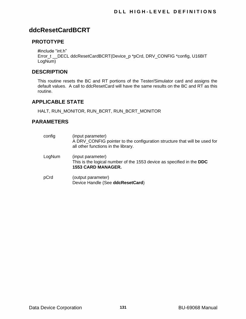
D L L H I G H - L E V E L D E F I N I T I O N S
Data Device Corporation BU-69068 Manual 131
ddcResetCardBCRT
PROTOTYPE
#include ―int.h‖ Error_t __DECL ddcResetCardBCRT(Device_p *pCrd, DRV_CONFIG *config, U16BIT LogNum)
DESCRIPTION
This routine resets the BC and RT portions of the Tester/Simulator card and assigns the default values. A call to ddcResetCard will have the same results on the BC and RT as this routine.
APPLICABLE STATE
HALT, RUN_MONITOR, RUN_BCRT, RUN_BCRT_MONITOR
PARAMETERS
config (input parameter)
A DRV_CONFIG pointer to the configuration structure that will be used for all other functions in the library.
LogNum (input parameter)
This is the logical number of the 1553 device as specified in the DDC
1553 CARD MANAGER. pCrd (output parameter)
Device Handle (See ddcResetCard)
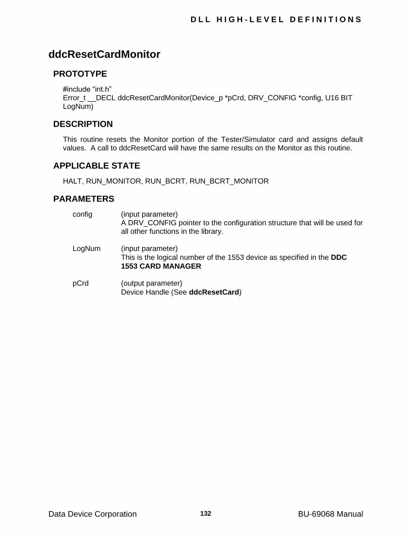
D L L H I G H - L E V E L D E F I N I T I O N S
Data Device Corporation BU-69068 Manual 132
ddcResetCardMonitor
PROTOTYPE
#include ―int.h‖ Error_t __DECL ddcResetCardMonitor(Device_p *pCrd, DRV_CONFIG *config, U16 BIT LogNum)
DESCRIPTION
This routine resets the Monitor portion of the Tester/Simulator card and assigns default values. A call to ddcResetCard will have the same results on the Monitor as this routine.
APPLICABLE STATE
HALT, RUN_MONITOR, RUN_BCRT, RUN_BCRT_MONITOR
PARAMETERS
config (input parameter) A DRV_CONFIG pointer to the configuration structure that will be used for
all other functions in the library.
LogNum (input parameter)
This is the logical number of the 1553 device as specified in the DDC
1553 CARD MANAGER pCrd (output parameter)
Device Handle (See ddcResetCard)

D L L H I G H - L E V E L D E F I N I T I O N S
Data Device Corporation BU-69068 Manual 133
ddcResetDBCAcceptance
PROTOTYPE
#include ―rt.h‖ Error_t __DECL ddcReset_dbc_acceptance (Device_p pCrd, S16BIT tadr, S16BIT immediate)
DESCRIPTION
This routine causes the card to reset the dynamic bus control acceptance bit in the RT's basic status response word while the RT is running.
APPLICABLE STATE
RUN_BCRT_MONITOR, RUN_BCRT
PARAMETERS
pCrd (input parameter)
Device Handle (See ddcResetCard) tadr (input parameter)
A S16BIT value in the range 0 - 30 which specifies the RT address.
immediate (input parameter)
A S16BIT value that specifies when to modify the basic status. If a BC is emulated, then the input value specified by the user is overridden by the value YES.
immediate = YES specifies that the basic status should be
modified immediately (provided that the BC and RT‘s are not currently transferring a message).
immediate = NO specifies that the basic status will be modified
after the next "end of message".
Error Condition (output parameter)
Note: If the RT is not in the middle of a message when one of the above routine is called and immediate = YES, then the next status word sent by the RT will contain the modified bit. If the RT is in the middle of a message when the above routine is called and immediate = YES, then the message will be aborted and the next status word sent by the RT will contain the modified bit. If immediate = NO, the modified status will appear only after the next message. However, there is no danger of a message being aborted. If this routine is called again before the card has had a chance to reset the bit - the routine returns the error code " ERROR_NOT_READY".

D L L H I G H - L E V E L D E F I N I T I O N S
Data Device Corporation BU-69068 Manual 134
ddcResetInstrumentation
PROTOTYPE
#include ―rt.h‖ Error_t __DECL ddcReset_instrumentation (Device_p pCrd, S16BIT tadr, S16BIT immediate)
DESCRIPTION
This routine causes the card to reset the instrumentation bit in the RT's basic status response word while the RT is running.
APPLICABLE STATE
RUN_BCRT_MONITOR, RUN_BCRT
PARAMETERS
pCrd (input parameter)
Device Handle (See ddcResetCard) tadr (input parameter)
A S16BIT value in the range 0 - 30 which specifies the RT address.
immediate (input parameter)
A S16BIT value that specifies when to modify the basic status. If a BC is emulated, then the input value specified by the user is overridden by the value YES.
immediate = YES specifies that the basic status should be
modified immediately (provided that the BC and RT‘s are not currently transferring a message).
immediate = NO specifies that the basic status will be modified
after the next "end of message".
Error Condition (output parameter)
Note: If the RT is not in the middle of a message when one of the above routine is called and immediate = YES, then the next status word sent by the RT will contain the modified bit. If the RT is in the middle of a message when the above routine is called and immediate = YES, then the message will be aborted and the next status word sent by the RT will contain the modified bit. If immediate = NO, the modified status will appear only after the next message. However, there is no danger of a message being aborted. If this routine is called again before the card has had a chance to reset the bit - the routine returns the error code " ERROR_NOT_READY".
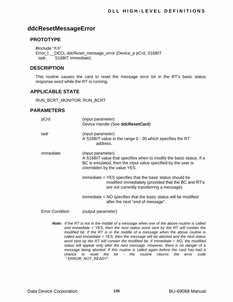
D L L H I G H - L E V E L D E F I N I T I O N S
Data Device Corporation BU-69068 Manual 135
ddcResetMessageError
PROTOTYPE
#include ―rt.h‖ Error_t __DECL ddcReset_message_error (Device_p pCrd, S16BIT tadr, S16BIT immediate)
DESCRIPTION
This routine causes the card to reset the message error bit in the RT's basic status response word while the RT is running.
APPLICABLE STATE
RUN_BCRT_MONITOR, RUN_BCRT
PARAMETERS
pCrd (input parameter)
Device Handle (See ddcResetCard) tadr (input parameter) A S16BIT value in the range 0 - 30 which specifies the RT
address. immediate (input parameter)
A S16BIT value that specifies when to modify the basic status. If a BC is emulated, then the input value specified by the user is overridden by the value YES.
immediate = YES specifies that the basic status should be
modified immediately (provided that the BC and RT‘s are not currently transferring a message).
immediate = NO specifies that the basic status will be modified
after the next "end of message". Error Condition (output parameter)
Note: If the RT is not in the middle of a message when one of the above routine is called and immediate = YES, then the next status word sent by the RT will contain the modified bit. If the RT is in the middle of a message when the above routine is called and immediate = YES, then the message will be aborted and the next status word sent by the RT will contain the modified bit. If immediate = NO, the modified status will appear only after the next message. However, there is no danger of a message being aborted. If this routine is called again before the card has had a chance to reset the bit - the routine returns the error code " ERROR_NOT_READY".
D L L H I G H - L E V E L D E F I N I T I O N S
Data Device Corporation BU-69068 Manual 136
ddcResetMon
PROTOTYPE
#include ―mt.h‖ Error_t __DECL ddcReset_mon(Device_p pCrd, S8BIT *bcrt_file, S8BIT *mon_file, S8BIT *imrlib_file)
DESCRIPTION
This routine is called to reset the monitor portion (only) of the Tester/Simulator card. A call to ddcResetCard will have the same results on the monitor as this routine.
APPLICABLE STATE
HALT, RUN_MONITOR, RUN_BCRT, RUN_BCRT_MONITOR
PARAMETERS
pCrd (input parameter)
Device Handle (See ddcResetCard) bcrt_file (input parameter) A S8BIT value. mon_file (input parameter) A S8BIT value. imrlib_file (input parameter) A S8BIT value. Error Condition (output parameter)
D L L H I G H - L E V E L D E F I N I T I O N S
Data Device Corporation BU-69068 Manual 137
ddcResetReservedBit
PROTOTYPE
#include ―rt.h‖ Error_t __DECL ddcReset_reserved_bit (Device_p pCrd, S16BIT tadr, S16BIT bit, S16BIT immediate)
DESCRIPTION
This routine causes the card to reset the reserved bit in the RT's basic status response word while the RT is running.
APPLICABLE STATE
RUN_BCRT_MONITOR, RUN_BCRT
PARAMETERS
pCrd (input parameter)
Device Handle (See ddcResetCard) tadr (input parameter)
A S16BIT value in the range 0 - 30 which specifies the RT address.
bit (input parameter) A S16BIT value specifying which Reserved bit to reset. immediate (input parameter)
A S16BIT value that specifies when to modify the basic status. If a BC is emulated, then the input value specified by the user is overridden by the value YES.
immediate = YES specifies that the basic status should be
modified immediately (provided that the BC and RT‘s are not currently transferring a message).
immediate = NO specifies that the basic status will be modified
after the next "end of message". Error Condition (output parameter)
Note: If the RT is not in the middle of a message when one of the above routine is called and immediate = YES, then the next status word sent by the RT will contain the modified bit. If the RT is in the middle of a message when the above routine is called and immediate = YES, then the message will be aborted and the next status word sent by the RT will contain the modified bit. If immediate = NO, the modified status will appear only after the next message. However, there is no danger of a message being aborted. If this routine is called again before the card has had a chance to reset the bit - the routine returns the error code " NOT_READY".
D L L H I G H - L E V E L D E F I N I T I O N S
Data Device Corporation BU-69068 Manual 138
ddcResetSerq
PROTOTYPE
#include ―rt.h‖ Error_t __DECL ddcReset_serq (Device_p pCrd, S16BIT tadr, S16BIT immediate)
DESCRIPTION
This routine causes the card to reset the service request bit in the RT's basic status response word while the RT is running.
APPLICABLE STATE
RUN_BCRT_MONITOR, RUN_BCRT
PARAMETERS
pCrd (input parameter)
Device Handle (See ddcResetCard) tadr (input parameter) A S16BIT value in the range 0 - 30 which specifies the RT
address. immediate (input parameter)
A S16BIT value that specifies when to modify the basic status. If a BC is emulated, then the input value specified by the user is overridden by the value YES.
immediate = YES specifies that the basic status should be
modified immediately (provided that the BC and RT‘s are not currently transferring a message).
immediate = NO specifies that the basic status will be modified
after the next "end of message". Error Condition (output parameter)
Note: If the RT is not in the middle of a message when one of the above routine is called and immediate = YES, then the next status word sent by the RT will contain the modified bit. If the RT is in the middle of a message when the above routine is called and immediate = YES, then the message will be aborted and the next status word sent by the RT will contain the modified bit. If immediate = NO, the modified status will appear only after the next message. However, there is no danger of a message being aborted. If this routine is called again before the card has had a chance to reset the bit - the routine returns the error code " NOT_READY".
D L L H I G H - L E V E L D E F I N I T I O N S
Data Device Corporation BU-69068 Manual 139
ddcResetSubsystem
PROTOTYPE
#include ―rt.h‖ Error_t __DECL ddcReset_subsystem (Device_p pCrd, S16BIT tadr, S16BIT immediate)
DESCRIPTION
This routine causes the card to reset the subsystem bit in the RT's basic status response word while the RT is running.
APPLICABLE STATE
RUN_BCRT_MONITOR, RUN_BCRT
PARAMETERS
pCrd (input parameter)
Device Handle (See ddcResetCard) tadr (input parameter)
A S16BIT value in the range 0 - 30 which specifies the RT address.
immediate (input parameter)
A S16BIT value that specifies when to modify the basic status. If a BC is emulated, then the input value specified by the user is overridden by the value YES.
immediate = YES specifies that the basic status should be
modified immediately (provided that the BC and RT‘s are not currently transferring a message).
immediate = NO specifies that the basic status will be modified
after the next "end of message". Error Condition (output parameter)
Note: If the RT is not in the middle of a message when one of the above routine is called and immediate = YES, then the next status word sent by the RT will contain the modified bit. If the RT is in the middle of a message when the above routine is called and immediate = YES, then the message will be aborted and the next status word sent by the RT will contain the modified bit. If immediate = NO, the modified status will appear only after the next message. However, there is no danger of a message being aborted. If this routine is called again before the card has had a chance to reset the bit - the routine returns the error code " NOT_READY".

D L L H I G H - L E V E L D E F I N I T I O N S
Data Device Corporation BU-69068 Manual 140
ddcResetTerminalFlag
PROTOTYPE
#include ―rt.h‖ Error_t __DECL ddcReset_terminal_flag (Device_p pCrd, S16BIT tadr, S16BIT immediate)
DESCRIPTION
This routine causes the card to reset the terminal flag bit in the RT's basic status response word while the RT is running.
APPLICABLE STATE
RUN_BCRT_MONITOR, RUN_BCRT
PARAMETERS
pCrd (input parameter)
Device Handle (See ddcResetCard) tadr (input parameter)
A S16BIT value in the range 0 - 30 which specifies the RT address.
immediate (input parameter)
A S16BIT value that specifies when to modify the basic status. If a BC is emulated, then the input value specified by the user is overridden by the value YES.
immediate = YES specifies that the basic status should be
modified immediately (provided that the BC and RT‘s are not currently transferring a message).
immediate = NO specifies that the basic status will be modified
after the next "end of message". Error Condition (output parameter)
Note: If the RT is not in the middle of a message when one of the above routine is called and immediate = YES, then the next status word sent by the RT will contain the modified bit. If the RT is in the middle of a message when the above routine is called and immediate = YES, then the message will be aborted and the next status word sent by the RT will contain the modified bit. If immediate = NO, the modified status will appear only after the next message. However, there is no danger of a message being aborted. If this routine is called again before the card has had a chance to reset the bit - the routine returns the error code " NOT_READY".
D L L H I G H - L E V E L D E F I N I T I O N S
Data Device Corporation BU-69068 Manual 141
ddcRunBc
PROTOTYPE
#include ―bc.h‖ Error_t __DECL ddcRun_bc(Device_p pCrd, S16BIT position, S32BIT times)
DESCRIPTION
This routine activates the BC and emulated RT‘s.
APPLICABLE STATE
HALT, RUN_MONITOR
PARAMETERS
pCrd (input parameter)
Device Handle (See ddcResetCard) position (input parameter)
A S16BIT value which specifies the position of the first entry in the frame to be executed by the BC. The range must be compatible
with the length of the frame as defined by ddcDefFrame Valid values: Must be less than the position of the
END_OF_MAJOR_FRAME symbol. times (input parameter)
A long integer in the range -1 - 100,000,000 which specifies the number of times the BC should send the frame; times = FOREVER (-1) specifies that the frame should be transmitted indefinitely.
Error Condition (output parameter)
D L L H I G H - L E V E L D E F I N I T I O N S
Data Device Corporation BU-69068 Manual 142
ddcRunContinue
PROTOTYPE
#include ―bc.h‖ Error_t __DECL ddcRun_continue (Device_p pCrd )
DESCRIPTION
This routine causes the BC and RT‘s to resume operation after being halted. The next message to be processed will be the next message in the frame list.
APPLICABLE STATE
HALT, RUN_MONITOR
PARAMETERS
pCrd (input parameter)
Device Handle (See ddcResetCard) Error Condition (output parameter)
D L L H I G H - L E V E L D E F I N I T I O N S
Data Device Corporation BU-69068 Manual 143
ddcRunMon
PROTOTYPE
#include ―mt.h‖ Error_t __DECL ddcRun_mon (Device_p pCrd)
DESCRIPTION
This routine activates the Monitor. Messages are stored starting from the beginning of the Monitor stack.
APPLICABLE STATE
HALT, RUN_BCRT
PARAMETERS
pCrd (input parameter)
Device Handle (See ddcResetCard) Error Condition (output parameter)
D L L H I G H - L E V E L D E F I N I T I O N S
Data Device Corporation BU-69068 Manual 144
ddcRunRt
PROTOTYPE
#include ―rt.h‖ Error_t __DECL ddcRun_rt (Device_p pCrd)
DESCRIPTION
This routine activates (only) the emulated RT‘s.
APPLICABLE STATE
HALT, RUN_MONITOR
PARAMETERS
pCrd (input parameter)
Device Handle (See ddcResetCard) Error Condition (output parameter)
D L L H I G H - L E V E L D E F I N I T I O N S
Data Device Corporation BU-69068 Manual 145
ddcSelectAllMessages
PROTOTYPE
#include ―mt.h‖ Error_t __DECL ddcSelect_all_messages (Device_p pCrd, U16BIT tadr)
DESCRIPTION
This routine specifies that all messages to a given RT shall be selected by the Monitor (by default all messages are selected).
APPLICABLE STATE
HALT
PARAMETERS
pCrd (input parameter)
Device Handle (See ddcResetCard) tadr (input parameter)
A U16BIT value in the range 0-31 which specifies the RT address. Error Condition (output parameter)
D L L H I G H - L E V E L D E F I N I T I O N S
Data Device Corporation BU-69068 Manual 146
ddcSelectBus
PROTOTYPE
#include ―mt.h‖ Error_t __DECL ddcSelect_bus (Device_p pCrd, U16BIT bus_a_state, U16BIT bus_b_state)
DESCRIPTION
This routine enables and inhibits the monitoring of messages on bus A and bus B.
APPLICABLE STATE
HALT
PARAMETERS
pCrd (input parameter)
Device Handle (See ddcResetCard) bus_a_state (input parameter) A U16BIT value that selects monitoring on bus A. Valid values: BUS_OPEN BUS_CLOSE bus_b_state (input parameter) A U16BIT value that selects monitoring on bus B. BUS_OPEN BUS_CLOSE Error Condition (output parameter)
D L L H I G H - L E V E L D E F I N I T I O N S
Data Device Corporation BU-69068 Manual 147
ddcSelectMessage
PROTOTYPE
#include ―mt.h‖ Error_t __DECL ddcSelect_message (Device_p pCrd, U16BIT tadr, U16BIT tr, U16BIT sadr)
DESCRIPTION
This routine specifies the messages to be selected or deselected by the Monitor. The decision is based on the values of RT address, T/R bit, and sub-address.
APPLICABLE STATE
HALT
PARAMETERS
Input pCrd (input parameter)
Device Handle (See ddcResetCard) tadr (input parameter) A U16BIT value in the range 0-31 which specifies the RT address. tr (input parameter) Specifies the direction of the message. Valid values: TRANSMIT RECEIVE sadr (input parameter)
A U16BIT value in the range 0-31 which specifies the sub-address.
Error Condition (output parameter)
D L L H I G H - L E V E L D E F I N I T I O N S
Data Device Corporation BU-69068 Manual 148
ddcSetAmp
PROTOTYPE
#include ―Int.h‖ Error_t __DECL ddcSetAmp (Device_p pCrd, S16BIT val)
DESCRIPTION
This routine defines the transmission amplitude of BC and RT bus traffic.
Note: This routine is only available for BU-65572i/72v/72T. The BU-65570i/v/T have fixed output 1553 bus outputs.
APPLICABLE STATE
HALT
PARAMETERS
pCrd (input parameter)
Device Handle (See ddcResetCard) val (input parameter)
A S16BIT value in the range 0-4095. Maximum amplitude corresponds to a value of 4095 (approximately 21 volts across a 77 ohm load connected to the card's twinax connector).
Error Condition (output parameter)
D L L H I G H - L E V E L D E F I N I T I O N S
Data Device Corporation BU-69068 Manual 149
ddcSetBcrtEvent
PROTOTYPE
#include ―irq.h‖ Error_t __DECL ddcSetBCRTEvent(Device_p pCrd, Error_t(*usr_handler)(Device_p pCrd, S16BIT type, S16BIT param))
DESCRIPTION
This routine defines the event handler for a BC/RT interrupt. The argument "usr_handler" is a pointer to a user routine which handles a BC/RT interrupt event. This routine allows interrupts on message or data table greater than 256.
Note: The event handler, specified by the user, is a routine with two arguments of type S16BIT. Through these two arguments the vector interrupt is passed from the BC/RT to the user. The user function must be declared as a “__DECL". This macro should be used, as the meaning of the macro (and ultimately the use of the function) may change in future versions.
APPLICABLE STATE
HALT
PARAMETERS
pCrd (input parameter)
Device Handle (See ddcResetCard) usr_handler (input parameter)
A pointer to the user interrupt handler routine. This function must be declared using the ―__DECL" macro which defines the calling convention.
Error Condition (output parameter)
D L L H I G H - L E V E L D E F I N I T I O N S
Data Device Corporation BU-69068 Manual 150
ddcSetBcrtEventEx
PROTOTYPE
#include ―irq.h‖ Error_t __DECL ddcSetBCRTEventEx(Device_p pCrd, Error_t(*usr_handler)(Device_p pCrd, S16BIT type, S16BIT SubType, S16BIT param))
DESCRIPTION
This routine defines the event handler for a BC/RT interrupt. The argument "usr_handler" is a pointer to a user routine which handles a BC/RT interrupt event.
Note: The event handler, specified by the user, is a routine with three arguments of type
S16BIT. Through these three arguments the vector interrupt is passed from the BC/RT to the user. The user function must be declared as a “__DECL". This macro should be used, as the meaning of the macro (and ultimately the use of the function) may change in future versions.
APPLICABLE STATE
HALT
PARAMETERS
pCrd (input parameter)
Device Handle (See ddcResetCard) usr_handler (input parameter)
A pointer to the user interrupt handler routine. This function must be declared using the ―__DECL" macro which defines the calling convention.
Error Condition (output parameter)
D L L H I G H - L E V E L D E F I N I T I O N S
Data Device Corporation BU-69068 Manual 151
ddcSetBroadcast
PROTOTYPE
#include ―rt.h‖ Error_t __DECL ddcSet_broadcast (Device_p pCrd, S16BIT tadr, S16BIT immediate)
DESCRIPTION
This routine causes the card to set the broadcast bit in the RT's basic status response word while the RT is running.
APPLICABLE STATE
RUN_BCRT_MONITOR, RUN_BCRT
PARAMETERS
pCrd (input parameter)
Device Handle (See ddcResetCard) tadr (input parameter)
A S16BIT value in the range 0 - 30 which specifies the RT address.
immediate (input parameter)
A S16BIT value that specifies when to modify the basic status. If a BC is emulated, then the input value specified by the user is overridden by the value YES.
immediate = YES specifies that the basic status should be
modified immediately (provided that the BC and RT‘s are not currently transferring a message).
immediate = NO specifies that the basic status will be modified
after the next "end of message".
Error Condition (output parameter)
Note: If the RT is not in the middle of a message when the above routine is called and immediate = YES, then the next status word sent by the RT will contain the modified bit. If the RT is in the middle of a message when the above routine is called and immediate = YES, then the message will be aborted and the next status word sent by the RT will contain the modified bit. If immediate = NO, the modified status will appear only after the next message. However, there is no danger of a message being aborted. If this routine is called again before the card has had a chance to set the bit - the routine returns the error code " NOT_READY".

D L L H I G H - L E V E L D E F I N I T I O N S
Data Device Corporation BU-69068 Manual 152
ddcSetBusy
PROTOTYPE
#include ―rt.h‖ Error_t __DECL ddcSet_busy (Device_p pCrd, S16BIT tadr, S16BIT immediate)
DESCRIPTION
This routine causes the card to set the busy bit in the RT's basic status response word while the RT is running.
APPLICABLE STATE
RUN_BCRT_MONITOR, RUN_BCRT
PARAMETERS
pCrd (input parameter)
Device Handle (See ddcResetCard) tadr (input parameter)
A S16BIT value in the range 0 - 30 which specifies the RT address.
immediate (input parameter)
A S16BIT value that specifies when to modify the basic status. If a BC is emulated, then the input value specified by the user is overridden by the value YES.
immediate = YES specifies that the basic status should be
modified immediately (provided that the BC and RT‘s are not currently transferring a message).
immediate = NO specifies that the basic status will be modified
after the next "end of message". Error Condition (output parameter)
Note: If the RT is not in the middle of a message when one of the above routine is called and immediate = YES, then the next status word sent by the RT will contain the modified bit. If the RT is in the middle of a message when the above routine is called and immediate = YES, then the message will be aborted and the next status word sent by the RT will contain the modified bit. If immediate = NO, the modified status will appear only after the next message. However, there is no danger of a message being aborted. If this routine is called again before the card has had a chance to set the bit - the routine returns the error code "READY".

D L L H I G H - L E V E L D E F I N I T I O N S
Data Device Corporation BU-69068 Manual 153
ddcSetBusyResetSrq
PROTOTYPE
#include ―rt.h‖ Error_t __DECL ddcSet_busy_reset_srq(Device_p pCrd, S16BIT tadr, S16BIT immediate)
DESCRIPTION
This routine is called to set the busy bit in the RT status word.
APPLICABLE STATE
HALT, RUN_BCRT, RUN_BCRT_MONITOR
PARAMETERS
pCrd (input parameter)
Device Handle (See ddcResetCard) tadr (input parameter)
A S16BIT value in the range 0 - 30 which specifies the RT address.
immediate = YES specifies that the basic status should be
modified immediately (provided that the BC and RT‘s are not currently transferring a message).
immediate = NO specifies that the basic status will be modified
after the next "end of message". Error Condition (output parameter)
D L L H I G H - L E V E L D E F I N I T I O N S
Data Device Corporation BU-69068 Manual 154
ddcSetCoupling
PROTOTYPE
#include ―int.h‖ Error_t __DECL ddcSetCoupling(Device_p pCrd,U16BIT Coupling, U16BIT Termination)
DESCRIPTION
This routine is used to set the coupling on the BU-65570/2iX, BU-65570/2TX and BU-
65570/2vX cards.
APPLICABLE STATE
HALT, RUN_BCRT_MONITOR, RUN_MONITOR
PARAMETERS
pCrd (input parameter)
Device Handle (See ddcResetCard) Coupling (input parameter)
A U16BIT value that represents the coupling on the Tester/Simulator card.
Valid Values: COUPLING_DIRECT COUPLING_TRANSFORMER Termination (input parameter)
A U16BIT value that represents the Termination on the Tester/Simulator Card.
Valid Values: TERMINATION_NONE TERMINATION_HALF TERMINATION_FULL Error Condition (output parameter)
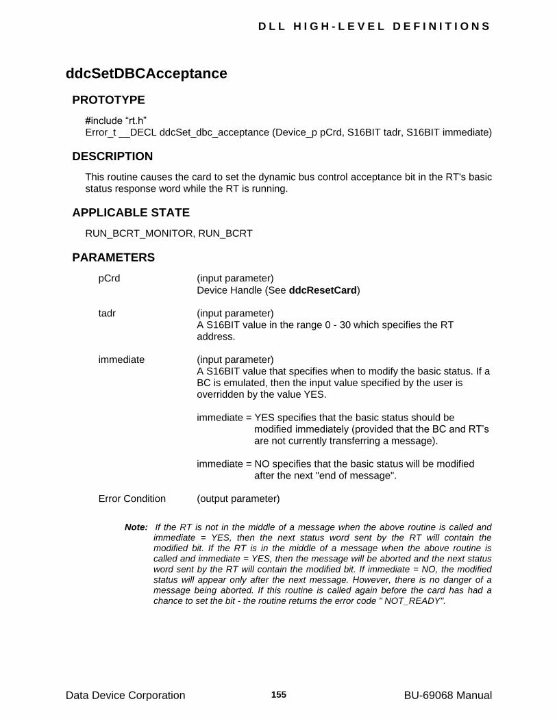
D L L H I G H - L E V E L D E F I N I T I O N S
Data Device Corporation BU-69068 Manual 155
ddcSetDBCAcceptance
PROTOTYPE
#include ―rt.h‖ Error_t __DECL ddcSet_dbc_acceptance (Device_p pCrd, S16BIT tadr, S16BIT immediate)
DESCRIPTION
This routine causes the card to set the dynamic bus control acceptance bit in the RT's basic status response word while the RT is running.
APPLICABLE STATE
RUN_BCRT_MONITOR, RUN_BCRT
PARAMETERS
pCrd (input parameter)
Device Handle (See ddcResetCard) tadr (input parameter)
A S16BIT value in the range 0 - 30 which specifies the RT address.
immediate (input parameter)
A S16BIT value that specifies when to modify the basic status. If a BC is emulated, then the input value specified by the user is overridden by the value YES.
immediate = YES specifies that the basic status should be
modified immediately (provided that the BC and RT‘s are not currently transferring a message).
immediate = NO specifies that the basic status will be modified
after the next "end of message". Error Condition (output parameter)
Note: If the RT is not in the middle of a message when the above routine is called and immediate = YES, then the next status word sent by the RT will contain the modified bit. If the RT is in the middle of a message when the above routine is called and immediate = YES, then the message will be aborted and the next status word sent by the RT will contain the modified bit. If immediate = NO, the modified status will appear only after the next message. However, there is no danger of a message being aborted. If this routine is called again before the card has had a chance to set the bit - the routine returns the error code " NOT_READY".

D L L H I G H - L E V E L D E F I N I T I O N S
Data Device Corporation BU-69068 Manual 156
ddcSetInstrumentation
PROTOTYPE
#include ―rt.h‖ Error_t __DECL ddcSet_instrumentation (Device_p pCrd, S16BIT tadr, S16BIT immediate)
DESCRIPTION
This routine causes the card to set the instrumentation bit in the RT's basic status response word while the RT is running.
APPLICABLE STATE
RUN_ BCRT_MONITOR, RUN_BCRT
PARAMETERS
pCrd (input parameter)
Device Handle (See ddcResetCard) tadr (input parameter)
A S16BIT value in the range 0 - 30 which specifies the RT address.
immediate (input parameter)
A S16BIT value that specifies when to modify the basic status. If a BC is emulated, then the input value specified by the user is overridden by the value YES.
immediate = YES specifies that the basic status should be
modified immediately (provided that the BC and RT‘s are not currently transferring a message).
immediate = NO specifies that the basic status will be modified
after the next "end of message". Error Condition (output parameter)
Note: If the RT is not in the middle of a message when the above routine is called and immediate = YES, then the next status word sent by the RT will contain the modified bit. If the RT is in the middle of a message when the above routine is called and immediate = YES, then the message will be aborted and the next status word sent by the RT will contain the modified bit. If immediate = NO, the modified status will appear only after the next message. However, there is no danger of a message being aborted. If this routine is called again before the card has had a chance to set the bit - the routine returns the error code " NOT_READY".
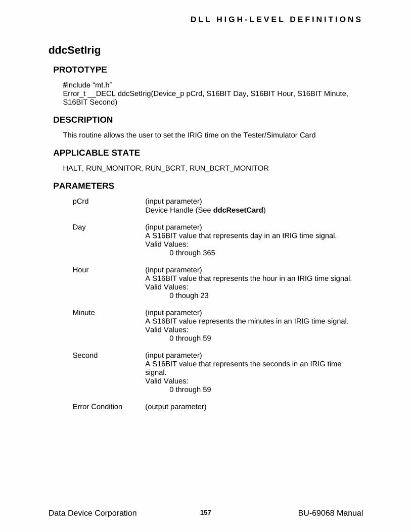
D L L H I G H - L E V E L D E F I N I T I O N S
Data Device Corporation BU-69068 Manual 157
ddcSetIrig
PROTOTYPE
#include ―mt.h‖ Error_t __DECL ddcSetIrig(Device_p pCrd, S16BIT Day, S16BIT Hour, S16BIT Minute, S16BIT Second)
DESCRIPTION
This routine allows the user to set the IRIG time on the Tester/Simulator Card
APPLICABLE STATE
HALT, RUN_MONITOR, RUN_BCRT, RUN_BCRT_MONITOR
PARAMETERS
pCrd (input parameter)
Device Handle (See ddcResetCard) Day (input parameter) A S16BIT value that represents day in an IRIG time signal. Valid Values: 0 through 365 Hour (input parameter) A S16BIT value that represents the hour in an IRIG time signal. Valid Values: 0 though 23 Minute (input parameter) A S16BIT value represents the minutes in an IRIG time signal. Valid Values: 0 through 59 Second (input parameter)
A S16BIT value that represents the seconds in an IRIG time signal.
Valid Values: 0 through 59 Error Condition (output parameter)
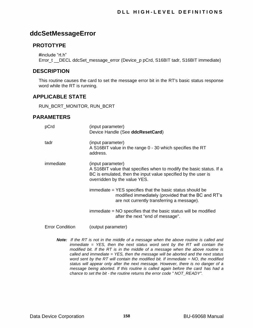
D L L H I G H - L E V E L D E F I N I T I O N S
Data Device Corporation BU-69068 Manual 158
ddcSetMessageError
PROTOTYPE
#include ―rt.h‖ Error_t __DECL ddcSet_message_error (Device_p pCrd, S16BIT tadr, S16BIT immediate)
DESCRIPTION
This routine causes the card to set the message error bit in the RT's basic status response word while the RT is running.
APPLICABLE STATE
RUN_BCRT_MONITOR, RUN_BCRT
PARAMETERS
pCrd (input parameter)
Device Handle (See ddcResetCard) tadr (input parameter)
A S16BIT value in the range 0 - 30 which specifies the RT address.
immediate (input parameter)
A S16BIT value that specifies when to modify the basic status. If a BC is emulated, then the input value specified by the user is overridden by the value YES.
immediate = YES specifies that the basic status should be
modified immediately (provided that the BC and RT‘s are not currently transferring a message).
immediate = NO specifies that the basic status will be modified
after the next "end of message". Error Condition (output parameter)
Note: If the RT is not in the middle of a message when the above routine is called and immediate = YES, then the next status word sent by the RT will contain the modified bit. If the RT is in the middle of a message when the above routine is called and immediate = YES, then the message will be aborted and the next status word sent by the RT will contain the modified bit. If immediate = NO, the modified status will appear only after the next message. However, there is no danger of a message being aborted. If this routine is called again before the card has had a chance to set the bit - the routine returns the error code " NOT_READY".
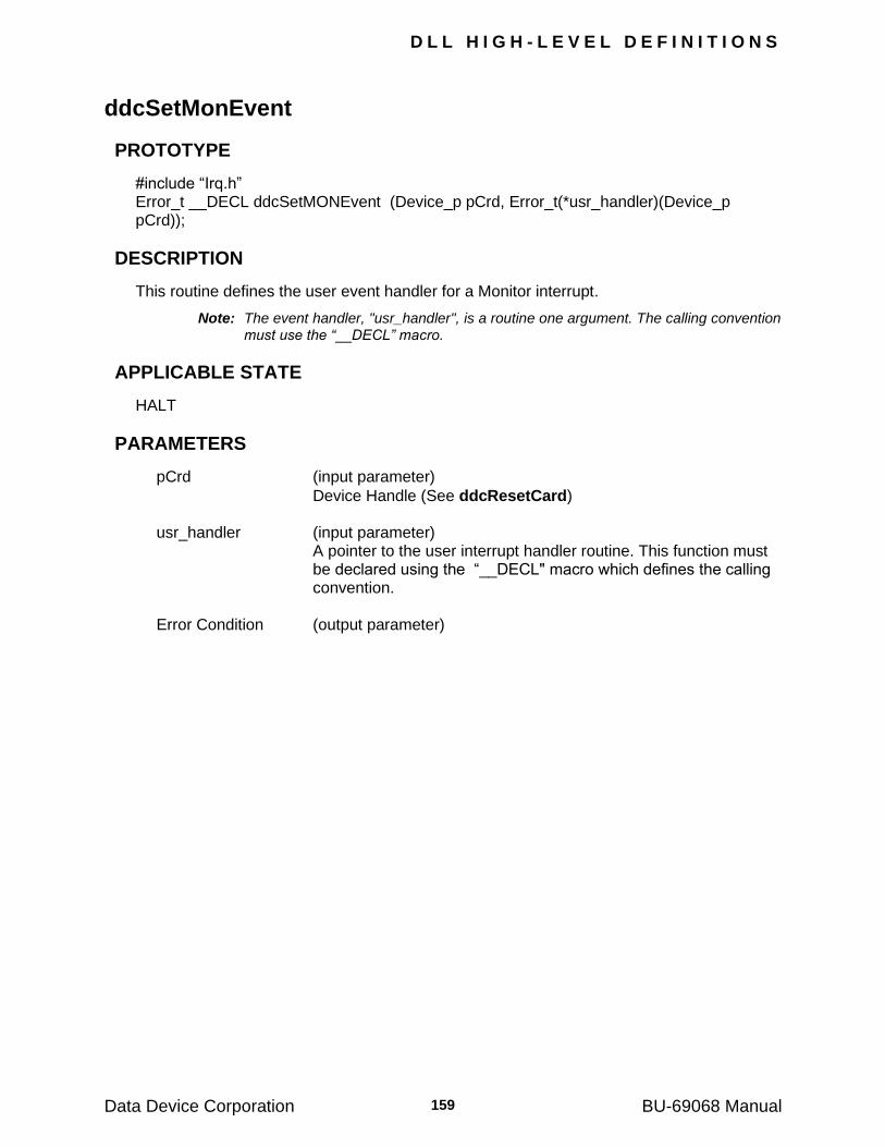
D L L H I G H - L E V E L D E F I N I T I O N S
Data Device Corporation BU-69068 Manual 159
ddcSetMonEvent
PROTOTYPE
#include ―Irq.h‖ Error_t __DECL ddcSetMONEvent (Device_p pCrd, Error_t(*usr_handler)(Device_p pCrd));
DESCRIPTION
This routine defines the user event handler for a Monitor interrupt.
Note: The event handler, "usr_handler", is a routine one argument. The calling convention must use the “__DECL” macro.
APPLICABLE STATE
HALT
PARAMETERS
pCrd (input parameter)
Device Handle (See ddcResetCard) usr_handler (input parameter)
A pointer to the user interrupt handler routine. This function must be declared using the ―__DECL" macro which defines the calling convention.
Error Condition (output parameter)
D L L H I G H - L E V E L D E F I N I T I O N S
Data Device Corporation BU-69068 Manual 160
ddcSetReservedBit
PROTOTYPE
#include ―rt.h‖ Error_t __DECL ddcSet_reserved_bit (Device_p pCrd, S16BIT tadr, S16BIT bit, S16BIT immediate)
DESCRIPTION
This routine causes the card to set the reserved bit in the RT's basic status response word while the RT is running.
APPLICABLE STATE
RUN_BCRT_MONITOR, RUN_BCRT
PARAMETERS
pCrd (input parameter)
Device Handle (See ddcResetCard) tadr (input parameter)
A S16BIT value in the range 0 - 30 which specifies the RT address.
bit (input parameter) A S16BIT value specifying the Reserved bit to set. immediate (input parameter)
A S16BIT value that specifies when to modify the basic status. If a BC is emulated, then the input value specified by the user is overridden by the value YES.
immediate = YES specifies that the basic status should be
modified immediately (provided that the BC and RT‘s are not currently transferring a message).
immediate = NO specifies that the basic status will be modified
after the next "end of message". Error Condition (output parameter)
Note: If the RT is not in the middle of a message when the above routine is called and immediate = YES, then the next status word sent by the RT will contain the modified bit. If the RT is in the middle of a message when the above routine is called and immediate = YES, then the message will be aborted and the next status word sent by the RT will contain the modified bit. If immediate = NO, the modified status will appear only after the next message. However, there is no danger of a message being aborted. If this routine is called again before the card has had a chance to set the bit - the routine returns the error code " NOT_READY".
D L L H I G H - L E V E L D E F I N I T I O N S
Data Device Corporation BU-69068 Manual 161
ddcSetRespTimeout
PROTOTYPE
#include “int.h”
Error_t __DECL ddcSetRespTimeout (Device_p pCrd, S16BIT val)
DESCRIPTION
This routine defines the response timeout for the BC/RT and Monitor. The response timeout is the time that is allowed to pass between the end of the message being sent to the RT and the status response being returned to the BC. If, within this time, no status is received by the BC, then the message is said to have no response.
APPLICABLE STATE
HALT
PARAMETERS
pCrd (input parameter)
Device Handle (See ddcResetCard) val (input parameter)
A S16BIT values specifying the maximum time (in microseconds) before declaring a "no response timeout" error.
Valid values: 2 through 29 (microseconds) Error Condition (output parameter)

D L L H I G H - L E V E L D E F I N I T I O N S
Data Device Corporation BU-69068 Manual 162
ddcSetRtc
PROTOTYPE
#include ―rt.h‖ Error_t __DECL ddcSet_rtc (Device_p pCrd, U32BIT val)
DESCRIPTION
This routine sets the Real-Time Clock of the Monitor.
Note: The Monitor resets its RTC when ddcRunMon is called.
APPLICABLE STATE
HALT
PARAMETERS
pCrd (input parameter)
Device Handle (See ddcResetCard) val (input parameter)
A U32BIT value specifying the time to be loaded into the RTC of the Monitor
Error Condition (output parameter)
D L L H I G H - L E V E L D E F I N I T I O N S
Data Device Corporation BU-69068 Manual 163
ddcSetSerq
PROTOTYPE
#include ―rt.h‖ Error_t __DECL ddcSet_serq (Device_p pCrd, S16BIT tadr, S16BIT immediate)
DESCRIPTION
This routine causes the card to set the service request bit in the RT's basic status response word while the RT is running.
APPLICABLE STATE
RUN_BCRT_MONITOR, RUN_BCRT
PARAMETERS
pCrd (input parameter)
Device Handle (See ddcResetCard) tadr (input parameter) A S16BIT value in the range 0 - 30 which specifies the RT
address. immediate (input parameter)
A S16BIT value that specifies when to modify the basic status. If a BC is emulated, then the input value specified by the user is overridden by the value YES.
immediate = YES specifies that the basic status should be
modified immediately (provided that the BC and RT‘s are not currently transferring a message).
immediate = NO specifies that the basic status will be modified
after the next "end of message". Error Condition (output parameter)
Note: If the RT is not in the middle of a message when the above routine is called and immediate = YES, then the next status word sent by the RT will contain the modified bit. If the RT is in the middle of a message when the above routine is called and immediate = YES, then the message will be aborted and the next status word sent by the RT will contain the modified bit. If immediate = NO, the modified status will appear only after the next message. However, there is no danger of a message being aborted. If this routine is called again before the card has had a chance to set the bit - the routine returns the error code "NOT_READY".

D L L H I G H - L E V E L D E F I N I T I O N S
Data Device Corporation BU-69068 Manual 164
ddcSetSubsystem
PROTOTYPE
#include ―rt.h‖ Error_t __DECL ddcSet_subsystem (Device_p pCrd, S16BIT tadr,S16BIT immediate)
DESCRIPTION
This routine causes the card to set the subsystem bit in the RT's basic status response word while the RT is running.
APPLICABLE STATE
RUN_BCRT_MONITOR, RUN_BCRT
PARAMETERS
pCrd (input parameter)
Device Handle (See ddcResetCard) tadr (input parameter)
A S16BIT value in the range 0 - 30 which specifies the RT address.
immediate (input parameter)
A S16BIT value that specifies when to modify the basic status. If a BC is emulated, then the input value specified by the user is overridden by the value YES.
immediate = YES specifies that the basic status should be
modified immediately (provided that the BC and RT‘s are not currently transferring a message).
immediate = NO specifies that the basic status will be modified
after the next "end of message". Error Condition (output parameter)
Note: If the RT is not in the middle of a message when the above routine is called and immediate = YES, then the next status word sent by the RT will contain the modified bit. If the RT is in the middle of a message when the above routine is called and immediate = YES, then the message will be aborted and the next status word sent by the RT will contain the modified bit. If immediate = NO, the modified status will appear only after the next message. However, there is no danger of a message being aborted. If this routine is called again before the card has had a chance to set the bit - the routine returns the error code "NOT_READY".
D L L H I G H - L E V E L D E F I N I T I O N S
Data Device Corporation BU-69068 Manual 165
ddcSetTerminalFlag
PROTOTYPE
#include ―rt.h‖ Error_t __DECL ddcSet_terminal_flag (Device_p pCrd, S16BIT tadr, S16BIT immediate)
DESCRIPTION
This routine causes the card to set the terminal flag bit in the RT's basic status response word while the RT is running.
APPLICABLE STATE
RUN_BCRT_MONITOR, RUN_BCRT
PARAMETERS
pCrd (input parameter)
Device Handle (See ddcResetCard) tadr (input parameter)
A S16BIT value in the range 0 - 30 which specifies the RT address.
immediate (input parameter)
A S16BIT value that specifies when to modify the basic status. If a BC is emulated, then the input value specified by the user is overridden by the value YES.
immediate = YES specifies that the basic status should be
modified immediately (provided that the BC and RT‘s are not currently transferring a message).
immediate = NO specifies that the basic status will be modified
after the next "end of message". Error Condition (output parameter)
Note: If the RT is not in the middle of a message when the above routine is called and immediate = YES, then the next status word sent by the RT will contain the modified bit. If the RT is in the middle of a message when the above routine is called and immediate = YES, then the message will be aborted and the next status word sent by the RT will contain the modified bit. If immediate = NO, the modified status will appear only after the next message. However, there is no danger of a message being aborted. If this routine is called again before the card has had a chance to set the bit - the routine returns the error code "NOT_READY".
D L L H I G H - L E V E L D E F I N I T I O N S
Data Device Corporation BU-69068 Manual 166
ddcShutDownIdea
PROTOTYPE
#include ―int.h‖ Error_t __DECL ddcShutDownIdea (Device_p *pCrd)
DESCRIPTION
This routine shuts down the BU-65570/2i, BU-65570/2T, BU65570/72v and BU-65570M cards. The routine disables the interrupt support, the DMA, and resets the DSP on the card to a known state.
APPLICABLE STATE
RESET, HALT, RUN_BCRT, RUN_MONITOR, RUN_BCRT_MONITOR
PARAMETERS
pCrd (input parameter)
Device Handle (See ddcResetCard) Error Condition (output parameter)
Note: Note that a pointer to pCrd is passed into the function.
D L L H I G H - L E V E L D E F I N I T I O N S
Data Device Corporation BU-69068 Manual 167
ddcSkipNextMessage
PROTOTYPE
#include ―bc.h‖ Error_t __DECL ddcSkip_next_message (Device_p pCrd, S16BIT yes_no)
DESCRIPTION
This routine enables and disables intermessage routine 31 (skip next message). Refer to Appendix C on intermessage routines for a full explanation of intermessage routine 31.
APPLICABLE STATE
HALT, RUN_MONITOR, RUN_BCRT, RUN_BCRT_MONITOR
PARAMETERS
pCrd (input parameter)
Device Handle (See ddcResetCard) yes_no (input parameter)
A S16BIT value that will specify whether or not the intermessage routine 31 should be enabled.
Valid values: YES NO Error Condition (output parameter)
D L L H I G H - L E V E L D E F I N I T I O N S
Data Device Corporation BU-69068 Manual 168
ddcSynchronizeAllCards
PROTOTYPE
#include ―rt.h‖ Error_t __DECL ddcSynchronizeAllCards()
DESCRIPTION
This routine will synchronize all the Tester/Simulator cards. This function will reset the real time clock of the monitor, and synchronize it with all other Tester/Simulator cards. The Bus Controller must be in the halt state to use this function. If the Bus Controller is in the run state a call to ddcHalt_bcrt() is required before the call to ddcSynchronizeAllCards(). To restart the Bus Controller at the point in which it was halted, call ddcRun_continue().
APPLICABLE STATE
HALT, RUN_MONITOR
PARAMETERS
Error Condition (output parameter)
D L L H I G H - L E V E L D E F I N I T I O N S
Data Device Corporation BU-69068 Manual 169
ddcWriteData
PROTOTYPE
#include ―bc.h‖ Error_t __DECL ddcWrite_data (Device_p pCrd, S16BIT id, S16BIT *buf, S16BIT count, S16BIT pos)
DESCRIPTION
This routine updates the selected data table. This is performed asynchronously with the communication. Thus, there is no guarantee that a table will not be updated while in use. However, if data tables are double-buffered, first the data is updated in shared memory and then the table pointer for communication is updated, thus ensuring data integrity. This routine may be called while communication is in progress.
APPLICABLE STATE
HALT, RUN_BCRT_MONITOR, RUN_MONITOR, RUN_BCRT
PARAMETERS
pCrd (input parameter)
Device Handle (See ddcResetCard) id (input parameter) A S16BIT value in the range 0-1023 which identifies the table buf (input parameter)
A S16BIT pointer to the buffer that contains the information to be copied to the data table in card memory.
count (input parameter)
A S16BIT value in the range 1-32 specifying the number of words to be copied.
pos (input parameter)
A S16BIT value specifying the relative location in the table to which the data should be copied. The number one (1) specifies the first location in the buffer and the data table. Therefore, if the data in the buffer should be written to the data table following word 5, this parameter should be set to 6.
Error Condition (output parameter)
D L L H I G H - L E V E L D E F I N I T I O N S
Data Device Corporation BU-69068 Manual 170
ddcWriteModeData
PROTOTYPE
#include ―rt.h‖ Error_t __DECL ddcWrite_mode_data (Device_p pCrd, S16BIT tadr, S16BIT mode_code, S16BIT val)
DESCRIPTION
This routine defines a data word associated with mode commands (except for "Transmit Last Command Word" and "Transmit Last Status Word") for a given terminal address. The data word sent by the BC is defined by specifying the BC's terminal address.
APPLICABLE STATE
HALT, RUN_BCRT_MONITOR, RUN_MONITOR, RUN_BCRT
PARAMETERS
pCrd (input parameter)
Device Handle (See ddcResetCard) tadr (input parameter)
A S16BIT value in the range 0-31 which defines the terminal address of an internal RT or the BC.
mode_code (input parameter)
A S16BIT value in the range 16-31 which specifies the mode code.
val (input parameter)
A S16BIT value that contains the data that should be written to the mode code.
Error Condition (output parameter)
D L L H I G H - L E V E L D E F I N I T I O N S
Data Device Corporation BU-69068 Manual 171
ddcVxCreateDevs
PROTOTYPE
#include ―vxworks.h‖ S16BIT ddcVxCreateDevs (U16BIT wIrqLevel)
DESCRIPTION
This routine is used to setup ALL Tester/Simulator VME cards in the system. This function should be run once per power on of the system. Once the routine is run, each channel will have a unique logical device number which can then be used by ddcResetCard to access the correct channel. The level which the Tester/Simulator cards will use to generate interrupts must be passed as a parameter. This routine returns the number of channels configured in the system.
APPLICABLE STATE
HALT, RUN_BCRT_MONITOR, RUN_MONITOR, RUN_BCRT
PARAMETERS
wIrqLevel (input parameter) a 16-bit parameter. Bits 7-0 are the PCI interrupt vector used by the
single board computer. Bits 15-8 are the VME interrupt level to be used by the card.
Output The number of channels found on the system or 0 for no cards found.
D L L H I G H - L E V E L D E F I N I T I O N S
Data Device Corporation BU-69068 Manual 172
ddcVxGetDevInfo
PROTOTYPE
#include ―vxworks.h‖ S16BIT ddcVxGetDevInfo (S16BIT wDevNum, U16BIT *pLA, U16BIT *pChannel)
DESCRIPTION
This routine is used to retrieve information associated with a mapped logical device. The channel is fully specified by its Logical Address and its channel number (0-3).
APPLICABLE STATE
HALT, RUN_BCRT_MONITOR, RUN_MONITOR, RUN_BCRT
PARAMETERS
wDevNum (input parameter) The logical device number of the installed card. Return (input parameter) 0 if successful, otherwise –1. pLA (input parameter)
The address of a 16-bit buffer. When the routine is run the VXI logical address of the card will be returned to this address.
pChannel (input parameter)
The address of a 16-bit buffer. The channel on the card (0-3) will be returned to this address.
D L L H I G H - L E V E L D E F I N I T I O N S
Data Device Corporation BU-69068 Manual 173
ddcVxGetDevNum
PROTOTYPE
#include ―vxworks.h‖ S16BIT ddcVxGetDevNum (S16BIT *pDevNum, U16BIT wLA, U16BIT wChannel)
DESCRIPTION
This routine is used to retrieve a logical device number associated with a particular channel. The channel is fully specified by its Logical Address and Channel Number.
APPLICABLE STATE
HALT, RUN_BCRT_MONITOR, RUN_MONITOR, RUN_BCRT
PARAMETERS
Input wLA (input parameter) The VXI logical address of the card. wChannel (input parameter) The channel on the card (0-3). Return (output parameter) 0 if successful, otherwise –1. pDevNum (output parameter)
The address of a 16-bit buffer. The logical device number will be returned to this dereferenced pointer The returned value must be passed to the ―LogNum‖ parameter of the ddcResetCard function.
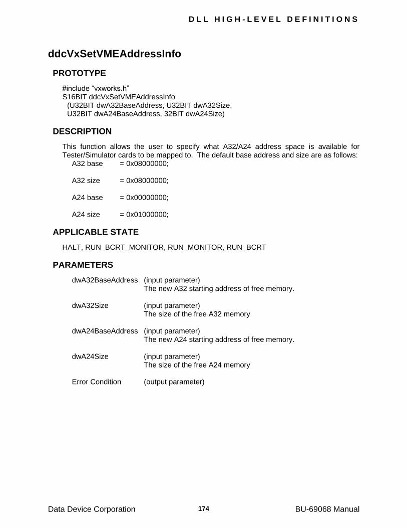
D L L H I G H - L E V E L D E F I N I T I O N S
Data Device Corporation BU-69068 Manual 174
ddcVxSetVMEAddressInfo
PROTOTYPE
#include ―vxworks.h‖ S16BIT ddcVxSetVMEAddressInfo (U32BIT dwA32BaseAddress, U32BIT dwA32Size, U32BIT dwA24BaseAddress, 32BIT dwA24Size)
DESCRIPTION
This function allows the user to specify what A32/A24 address space is available for Tester/Simulator cards to be mapped to. The default base address and size are as follows: A32 base = 0x08000000; A32 size = 0x08000000; A24 base = 0x00000000; A24 size = 0x01000000;
APPLICABLE STATE
HALT, RUN_BCRT_MONITOR, RUN_MONITOR, RUN_BCRT
PARAMETERS
dwA32BaseAddress (input parameter) The new A32 starting address of free memory. dwA32Size (input parameter) The size of the free A32 memory dwA24BaseAddress (input parameter) The new A24 starting address of free memory. dwA24Size (input parameter) The size of the free A24 memory Error Condition (output parameter)
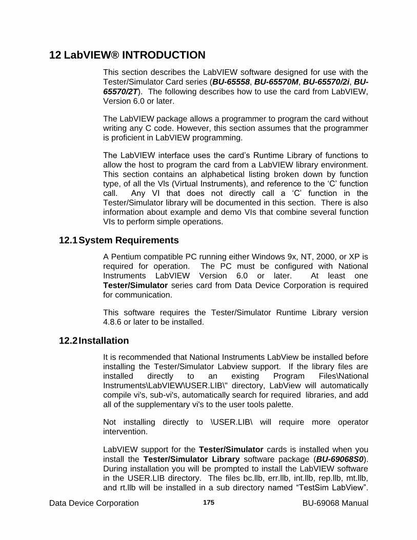
Data Device Corporation BU-69068 Manual
175
12 LabVIEW® INTRODUCTION
This section describes the LabVIEW software designed for use with the
Tester/Simulator Card series (BU-65558, BU-65570M, BU-65570/2i, BU-
65570/2T). The following describes how to use the card from LabVIEW, Version 6.0 or later.
The LabVIEW package allows a programmer to program the card without writing any C code. However, this section assumes that the programmer is proficient in LabVIEW programming.
The LabVIEW interface uses the card‘s Runtime Library of functions to allow the host to program the card from a LabVIEW library environment. This section contains an alphabetical listing broken down by function type, of all the Vls (Virtual Instruments), and reference to the ‗C‘ function call. Any VI that does not directly call a ‗C‘ function in the Tester/Simulator library will be documented in this section. There is also information about example and demo VIs that combine several function VIs to perform simple operations.
12.1 System Requirements
A Pentium compatible PC running either Windows 9x, NT, 2000, or XP is required for operation. The PC must be configured with National Instruments LabVIEW Version 6.0 or later. At least one
Tester/Simulator series card from Data Device Corporation is required for communication.
This software requires the Tester/Simulator Runtime Library version 4.8.6 or later to be installed.
12.2 Installation
It is recommended that National Instruments LabView be installed before installing the Tester/Simulator Labview support. If the library files are installed directly to an existing Program Files\National Instruments\LabVIEW\USER.LIB\" directory, LabView will automatically compile vi's, sub-vi's, automatically search for required libraries, and add all of the supplementary vi's to the user tools palette.
Not installing directly to \USER.LIB\ will require more operator intervention.
LabVIEW support for the Tester/Simulator cards is installed when you
install the Tester/Simulator Library software package (BU-69068S0). During installation you will be prompted to install the LabVIEW software in the USER.LIB directory. The files bc.llb, err.llb, int.llb, rep.llb, mt.llb, and rt.llb will be installed in a sub directory named ―TestSim LabView‖.
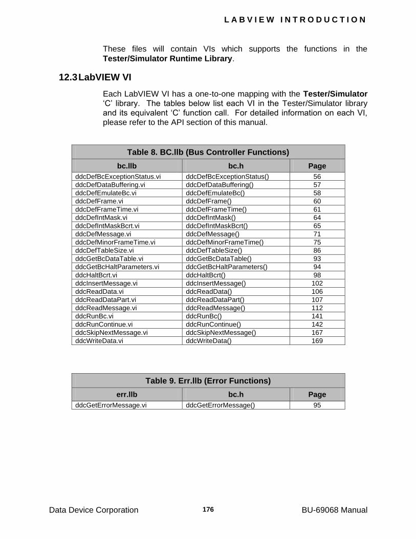
L A B V I E W I N T R O D U C T I O N
Data Device Corporation BU-69068 Manual 176
These files will contain VIs which supports the functions in the
Tester/Simulator Runtime Library.
12.3 LabVIEW VI
Each LabVIEW VI has a one-to-one mapping with the Tester/Simulator ‗C‘ library. The tables below list each VI in the Tester/Simulator library and its equivalent ‗C‘ function call. For detailed information on each VI, please refer to the API section of this manual.
Table 8. BC.llb (Bus Controller Functions)
bc.llb bc.h Page
ddcDefBcExceptionStatus.vi ddcDefBcExceptionStatus() 56
ddcDefDataBuffering.vi ddcDefDataBuffering() 57
ddcDefEmulateBc.vi ddcDefEmulateBc() 58
ddcDefFrame.vi ddcDefFrame() 60
ddcDefFrameTime.vi ddcDefFrameTime() 61
ddcDefIntMask.vi ddcDefIntMask() 64
ddcDefIntMaskBcrt.vi ddcDefIntMaskBcrt() 65
ddcDefMessage.vi ddcDefMessage() 71
ddcDefMinorFrameTime.vi ddcDefMinorFrameTime() 75
ddcDefTableSize.vi ddcDefTableSize() 86
ddcGetBcDataTable.vi ddcGetBcDataTable() 93
ddcGetBcHaltParameters.vi ddcGetBcHaltParameters() 94
ddcHaltBcrt.vi ddcHaltBcrt() 98
ddcInsertMessage.vi ddcInsertMessage() 102
ddcReadData.vi ddcReadData() 106
ddcReadDataPart.vi ddcReadDataPart() 107
ddcReadMessage.vi ddcReadMessage() 112
ddcRunBc.vi ddcRunBc() 141
ddcRunContinue.vi ddcRunContinue() 142
ddcSkipNextMessage.vi ddcSkipNextMessage() 167
ddcWriteData.vi ddcWriteData() 169
Table 9. Err.llb (Error Functions)
err.llb bc.h Page
ddcGetErrorMessage.vi ddcGetErrorMessage() 95
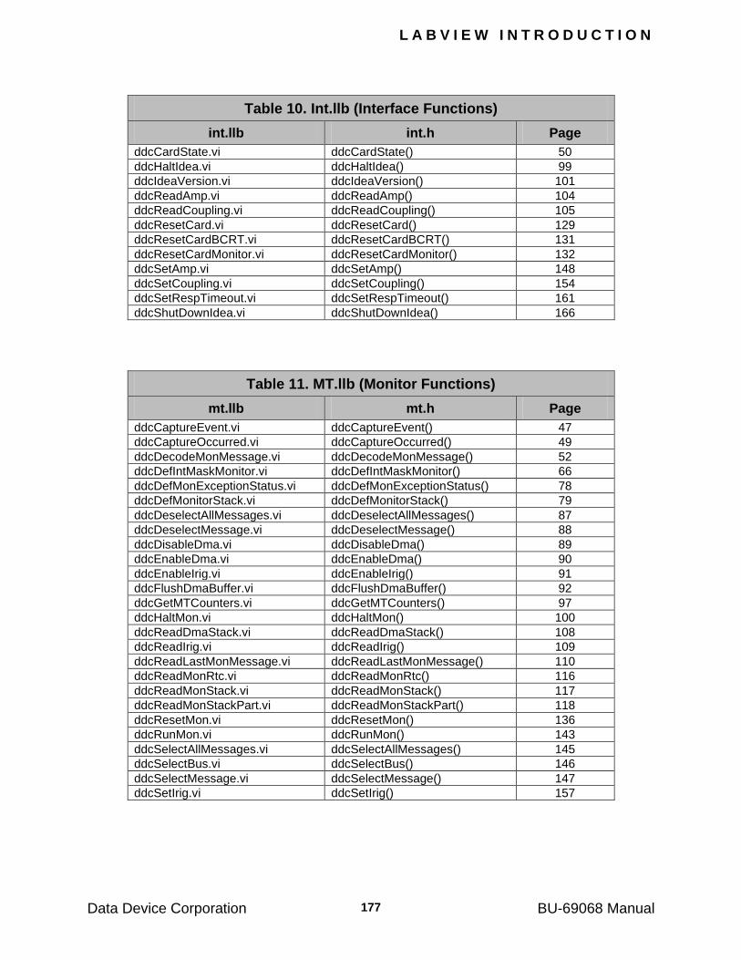
L A B V I E W I N T R O D U C T I O N
Data Device Corporation BU-69068 Manual 177
Table 10. Int.llb (Interface Functions)
int.llb int.h Page
ddcCardState.vi ddcCardState() 50
ddcHaltIdea.vi ddcHaltIdea() 99
ddcIdeaVersion.vi ddcIdeaVersion() 101
ddcReadAmp.vi ddcReadAmp() 104
ddcReadCoupling.vi ddcReadCoupling() 105
ddcResetCard.vi ddcResetCard() 129
ddcResetCardBCRT.vi ddcResetCardBCRT() 131
ddcResetCardMonitor.vi ddcResetCardMonitor() 132
ddcSetAmp.vi ddcSetAmp() 148
ddcSetCoupling.vi ddcSetCoupling() 154
ddcSetRespTimeout.vi ddcSetRespTimeout() 161
ddcShutDownIdea.vi ddcShutDownIdea() 166
Table 11. MT.llb (Monitor Functions)
mt.llb mt.h Page
ddcCaptureEvent.vi ddcCaptureEvent() 47
ddcCaptureOccurred.vi ddcCaptureOccurred() 49
ddcDecodeMonMessage.vi ddcDecodeMonMessage() 52
ddcDefIntMaskMonitor.vi ddcDefIntMaskMonitor() 66
ddcDefMonExceptionStatus.vi ddcDefMonExceptionStatus() 78
ddcDefMonitorStack.vi ddcDefMonitorStack() 79
ddcDeselectAllMessages.vi ddcDeselectAllMessages() 87
ddcDeselectMessage.vi ddcDeselectMessage() 88
ddcDisableDma.vi ddcDisableDma() 89
ddcEnableDma.vi ddcEnableDma() 90
ddcEnableIrig.vi ddcEnableIrig() 91
ddcFlushDmaBuffer.vi ddcFlushDmaBuffer() 92
ddcGetMTCounters.vi ddcGetMTCounters() 97
ddcHaltMon.vi ddcHaltMon() 100
ddcReadDmaStack.vi ddcReadDmaStack() 108
ddcReadIrig.vi ddcReadIrig() 109
ddcReadLastMonMessage.vi ddcReadLastMonMessage() 110
ddcReadMonRtc.vi ddcReadMonRtc() 116
ddcReadMonStack.vi ddcReadMonStack() 117
ddcReadMonStackPart.vi ddcReadMonStackPart() 118
ddcResetMon.vi ddcResetMon() 136
ddcRunMon.vi ddcRunMon() 143
ddcSelectAllMessages.vi ddcSelectAllMessages() 145
ddcSelectBus.vi ddcSelectBus() 146
ddcSelectMessage.vi ddcSelectMessage() 147
ddcSetIrig.vi ddcSetIrig() 157
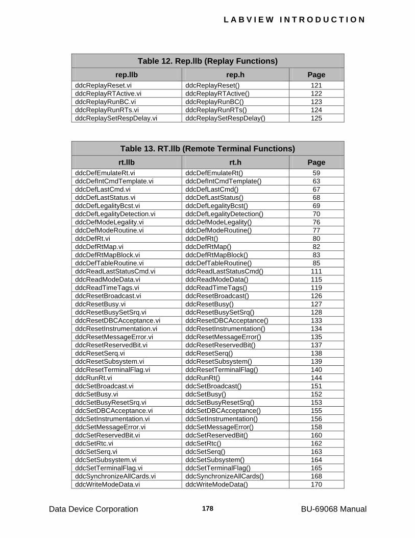
L A B V I E W I N T R O D U C T I O N
Data Device Corporation BU-69068 Manual 178
Table 12. Rep.llb (Replay Functions)
rep.llb rep.h Page
ddcReplayReset.vi ddcReplayReset() 121
ddcReplayRTActive.vi ddcReplayRTActive() 122
ddcReplayRunBC.vi ddcReplayRunBC() 123
ddcReplayRunRTs.vi ddcReplayRunRTs() 124
ddcReplaySetRespDelay.vi ddcReplaySetRespDelay() 125
Table 13. RT.llb (Remote Terminal Functions)
rt.llb rt.h Page
ddcDefEmulateRt.vi ddcDefEmulateRt() 59
ddcDefIntCmdTemplate.vi ddcDefIntCmdTemplate() 63
ddcDefLastCmd.vi ddcDefLastCmd() 67
ddcDefLastStatus.vi ddcDefLastStatus() 68
ddcDefLegalityBcst.vi ddcDefLegalityBcst() 69
ddcDefLegalityDetection.vi ddcDefLegalityDetection() 70
ddcDefModeLegality.vi ddcDefModeLegality() 76
ddcDefModeRoutine.vi ddcDefModeRoutine() 77
ddcDefRt.vi ddcDefRt() 80
ddcDefRtMap.vi ddcDefRtMap() 82
ddcDefRtMapBlock.vi ddcDefRtMapBlock() 83
ddcDefTableRoutine.vi ddcDefTableRoutine() 85
ddcReadLastStatusCmd.vi ddcReadLastStatusCmd() 111
ddcReadModeData.vi ddcReadModeData() 115
ddcReadTimeTags.vi ddcReadTimeTags() 119
ddcResetBroadcast.vi ddcResetBroadcast() 126
ddcResetBusy.vi ddcResetBusy() 127
ddcResetBusySetSrq.vi ddcResetBusySetSrq() 128
ddcResetDBCAcceptance.vi ddcResetDBCAcceptance() 133
ddcResetInstrumentation.vi ddcResetInstrumentation() 134
ddcResetMessageError.vi ddcResetMessageError() 135
ddcResetReservedBit.vi ddcResetReservedBit() 137
ddcResetSerq.vi ddcResetSerq() 138
ddcResetSubsystem.vi ddcResetSubsystem() 139
ddcResetTerminalFlag.vi ddcResetTerminalFlag() 140
ddcRunRt.vi ddcRunRt() 144
ddcSetBroadcast.vi ddcSetBroadcast() 151
ddcSetBusy.vi ddcSetBusy() 152
ddcSetBusyResetSrq.vi ddcSetBusyResetSrq() 153
ddcSetDBCAcceptance.vi ddcSetDBCAcceptance() 155
ddcSetInstrumentation.vi ddcSetInstrumentation() 156
ddcSetMessageError.vi ddcSetMessageError() 158
ddcSetReservedBit.vi ddcSetReservedBit() 160
ddcSetRtc.vi ddcSetRtc() 162
ddcSetSerq.vi ddcSetSerq() 163
ddcSetSubsystem.vi ddcSetSubsystem() 164
ddcSetTerminalFlag.vi ddcSetTerminalFlag() 165
ddcSynchronizeAllCards.vi ddcSynchronizeAllCards() 168
ddcWriteModeData.vi ddcWriteModeData() 170
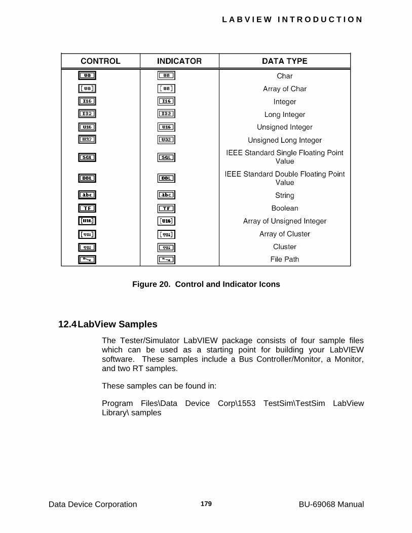
L A B V I E W I N T R O D U C T I O N
Data Device Corporation BU-69068 Manual 179
Figure 20. Control and Indicator Icons
12.4 LabView Samples
The Tester/Simulator LabVIEW package consists of four sample files which can be used as a starting point for building your LabVIEW software. These samples include a Bus Controller/Monitor, a Monitor, and two RT samples.
These samples can be found in:
Program Files\Data Device Corp\1553 TestSim\TestSim LabView Library\ samples
L A B V I E W I N T R O D U C T I O N
Data Device Corporation BU-69068 Manual 180
12.5 BC/MT Sample
The BCMTDemo.vi sample will setup and run the monitor while creating a 1 message frame. The message is created using the front panel controls. Each control should be set before pressing the Run button to activate the VI. After the Bus controller and monitor start, a call to read the monitor stack is issued and the message is decoded. After the message is decoded, it is displayed on the front panel, the card is halted, and the program will exit.
12.6 RT Sample
The RTdemo.vi sample is a simple RT example that enables the card for use as a single RT. A data table is assigned to a specific sub address. After the card is running, a call to read the data table is issued. The user can stop the program by clicking on the stop button, which will halt the
RT and shutdown the Tester/Simulator card.
Data Device Corporation BU-69068 Manual
181
13 VISUAL BASIC INTRODUCTION
This section describes the Visual Basic software designed for use with
the Tester/Simulator Card series (BU-65558, BU-65570M, BU-
65570/2i, BU-65570/2T). The following describes how to use the card using Visual Basic 6.0 or later.
The Visual Basic package allows a programmer to program the card without writing any C code. However, this section assumes that the programmer is proficient in Visual Basic programming.
The Visual Basic interface will use the card‘s Runtime Library of functions to allow the host to program the card from a LabVIEW library environment. This appendix contains an alphabetical listing broken down by function type, of all the VB function (Visual Basic), and reference to the ‗C‘ function call. Any VB function that does not directly call a ‗C‘ function in the Tester/Simulator library will be documented in this section. This appendix also contains information about examples and demos that combine several functions in VB to perform simple operations.
13.1 System Requirements
A Pentium compatible PC running either Windows 9x, NT, 2000, or XP is required for operation. The PC must be configured with Microsoft Visual
Basic 6.0. At least one Tester/Simulator series card from Data Device Corporation is required for communication.
This software requires the Tester/Simulator Runtime Library version 4.8.9 or later to be installed.
13.2 Installation
Visual Basic support for the Tester/Simulator library is installed when
you install the Tester/Simulator Library software package (BU-
69068S0). The bas files included are:
Bc.bas
Err.bas
Int.bas
Irq.bas
Mt.bas
Rep.bas
Rt.bas
TS_cons.bas
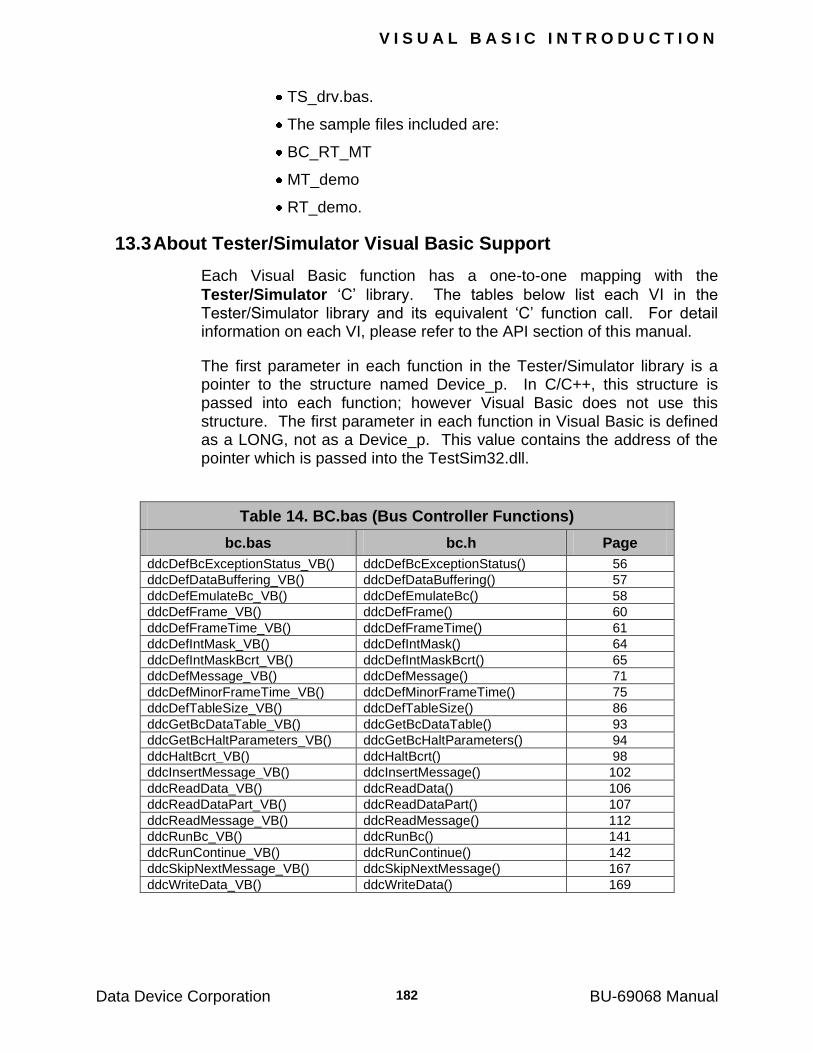
V I S U A L B A S I C I N T R O D U C T I O N
Data Device Corporation BU-69068 Manual 182
TS_drv.bas.
The sample files included are:
BC_RT_MT
MT_demo
RT_demo.
13.3 About Tester/Simulator Visual Basic Support
Each Visual Basic function has a one-to-one mapping with the
Tester/Simulator ‗C‘ library. The tables below list each VI in the Tester/Simulator library and its equivalent ‗C‘ function call. For detail information on each VI, please refer to the API section of this manual.
The first parameter in each function in the Tester/Simulator library is a pointer to the structure named Device_p. In C/C++, this structure is passed into each function; however Visual Basic does not use this structure. The first parameter in each function in Visual Basic is defined as a LONG, not as a Device_p. This value contains the address of the pointer which is passed into the TestSim32.dll.
Table 14. BC.bas (Bus Controller Functions)
bc.bas bc.h Page
ddcDefBcExceptionStatus_VB() ddcDefBcExceptionStatus() 56
ddcDefDataBuffering_VB() ddcDefDataBuffering() 57
ddcDefEmulateBc_VB() ddcDefEmulateBc() 58
ddcDefFrame_VB() ddcDefFrame() 60
ddcDefFrameTime_VB() ddcDefFrameTime() 61
ddcDefIntMask_VB() ddcDefIntMask() 64
ddcDefIntMaskBcrt_VB() ddcDefIntMaskBcrt() 65
ddcDefMessage_VB() ddcDefMessage() 71
ddcDefMinorFrameTime_VB() ddcDefMinorFrameTime() 75
ddcDefTableSize_VB() ddcDefTableSize() 86
ddcGetBcDataTable_VB() ddcGetBcDataTable() 93
ddcGetBcHaltParameters_VB() ddcGetBcHaltParameters() 94
ddcHaltBcrt_VB() ddcHaltBcrt() 98
ddcInsertMessage_VB() ddcInsertMessage() 102
ddcReadData_VB() ddcReadData() 106
ddcReadDataPart_VB() ddcReadDataPart() 107
ddcReadMessage_VB() ddcReadMessage() 112
ddcRunBc_VB() ddcRunBc() 141
ddcRunContinue_VB() ddcRunContinue() 142
ddcSkipNextMessage_VB() ddcSkipNextMessage() 167
ddcWriteData_VB() ddcWriteData() 169
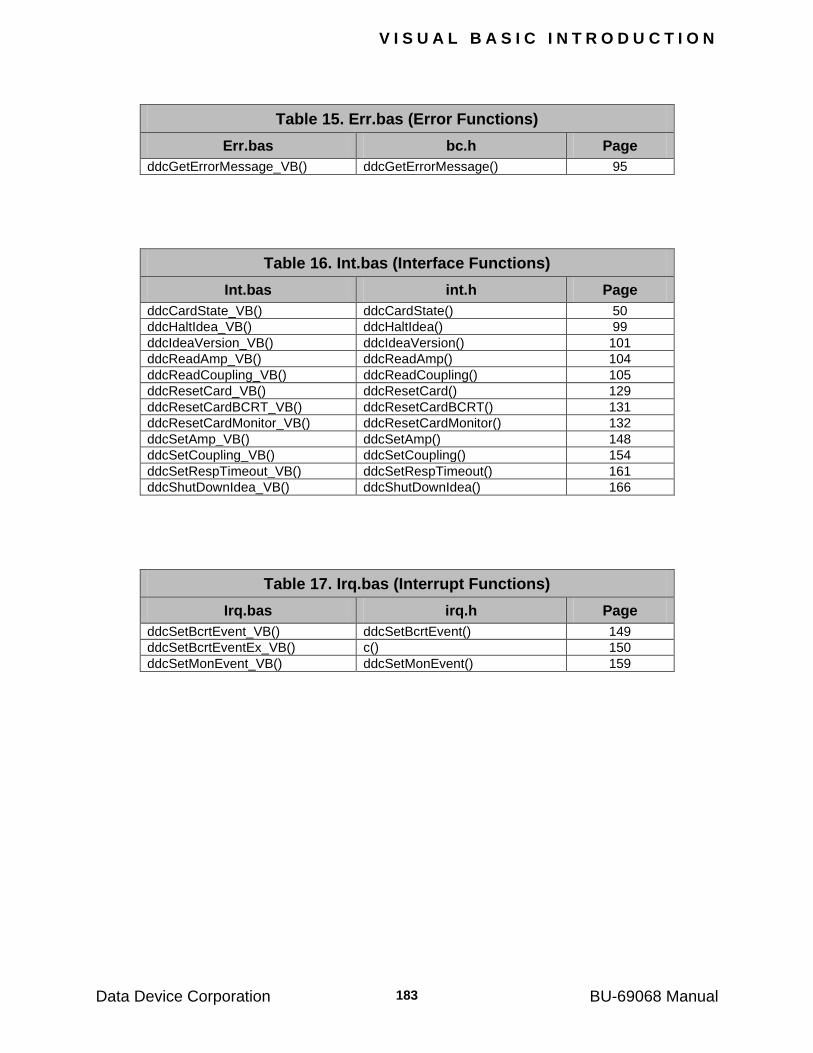
V I S U A L B A S I C I N T R O D U C T I O N
Data Device Corporation BU-69068 Manual 183
Table 15. Err.bas (Error Functions)
Err.bas bc.h Page
ddcGetErrorMessage_VB() ddcGetErrorMessage() 95
Table 16. Int.bas (Interface Functions)
Int.bas int.h Page
ddcCardState_VB() ddcCardState() 50
ddcHaltIdea_VB() ddcHaltIdea() 99
ddcIdeaVersion_VB() ddcIdeaVersion() 101
ddcReadAmp_VB() ddcReadAmp() 104
ddcReadCoupling_VB() ddcReadCoupling() 105
ddcResetCard_VB() ddcResetCard() 129
ddcResetCardBCRT_VB() ddcResetCardBCRT() 131
ddcResetCardMonitor_VB() ddcResetCardMonitor() 132
ddcSetAmp_VB() ddcSetAmp() 148
ddcSetCoupling_VB() ddcSetCoupling() 154
ddcSetRespTimeout_VB() ddcSetRespTimeout() 161
ddcShutDownIdea_VB() ddcShutDownIdea() 166
Table 17. Irq.bas (Interrupt Functions)
Irq.bas irq.h Page
ddcSetBcrtEvent_VB() ddcSetBcrtEvent() 149
ddcSetBcrtEventEx_VB() c() 150
ddcSetMonEvent_VB() ddcSetMonEvent() 159
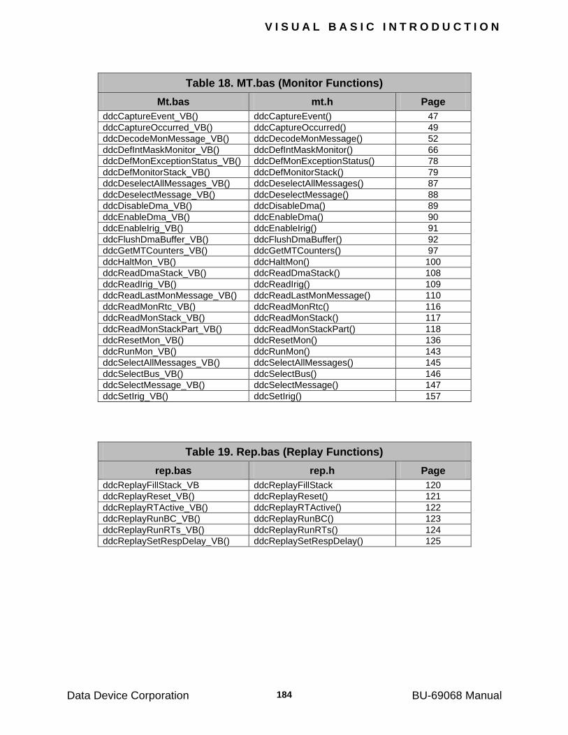
V I S U A L B A S I C I N T R O D U C T I O N
Data Device Corporation BU-69068 Manual 184
Table 18. MT.bas (Monitor Functions)
Mt.bas mt.h Page
ddcCaptureEvent_VB() ddcCaptureEvent() 47
ddcCaptureOccurred_VB() ddcCaptureOccurred() 49
ddcDecodeMonMessage_VB() ddcDecodeMonMessage() 52
ddcDefIntMaskMonitor_VB() ddcDefIntMaskMonitor() 66
ddcDefMonExceptionStatus_VB() ddcDefMonExceptionStatus() 78
ddcDefMonitorStack_VB() ddcDefMonitorStack() 79
ddcDeselectAllMessages_VB() ddcDeselectAllMessages() 87
ddcDeselectMessage_VB() ddcDeselectMessage() 88
ddcDisableDma_VB() ddcDisableDma() 89
ddcEnableDma_VB() ddcEnableDma() 90
ddcEnableIrig_VB() ddcEnableIrig() 91
ddcFlushDmaBuffer_VB() ddcFlushDmaBuffer() 92
ddcGetMTCounters_VB() ddcGetMTCounters() 97
ddcHaltMon_VB() ddcHaltMon() 100
ddcReadDmaStack_VB() ddcReadDmaStack() 108
ddcReadIrig_VB() ddcReadIrig() 109
ddcReadLastMonMessage_VB() ddcReadLastMonMessage() 110
ddcReadMonRtc_VB() ddcReadMonRtc() 116
ddcReadMonStack_VB() ddcReadMonStack() 117
ddcReadMonStackPart_VB() ddcReadMonStackPart() 118
ddcResetMon_VB() ddcResetMon() 136
ddcRunMon_VB() ddcRunMon() 143
ddcSelectAllMessages_VB() ddcSelectAllMessages() 145
ddcSelectBus_VB() ddcSelectBus() 146
ddcSelectMessage_VB() ddcSelectMessage() 147
ddcSetIrig_VB() ddcSetIrig() 157
Table 19. Rep.bas (Replay Functions)
rep.bas rep.h Page
ddcReplayFillStack_VB ddcReplayFillStack 120
ddcReplayReset_VB() ddcReplayReset() 121
ddcReplayRTActive_VB() ddcReplayRTActive() 122
ddcReplayRunBC_VB() ddcReplayRunBC() 123
ddcReplayRunRTs_VB() ddcReplayRunRTs() 124
ddcReplaySetRespDelay_VB() ddcReplaySetRespDelay() 125
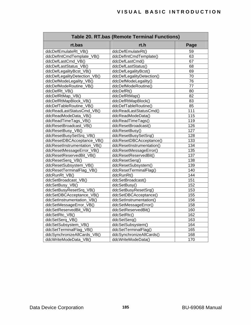
V I S U A L B A S I C I N T R O D U C T I O N
Data Device Corporation BU-69068 Manual 185
Table 20. RT.bas (Remote Terminal Functions)
rt.bas rt.h Page
ddcDefEmulateRt_VB() ddcDefEmulateRt() 59
ddcDefIntCmdTemplate_VB() ddcDefIntCmdTemplate() 63 ddcDefLastCmd_VB() ddcDefLastCmd() 67 ddcDefLastStatus_VB() ddcDefLastStatus() 68 ddcDefLegalityBcst_VB() ddcDefLegalityBcst() 69 ddcDefLegalityDetection_VB() ddcDefLegalityDetection() 70 ddcDefModeLegality_VB() ddcDefModeLegality() 76 ddcDefModeRoutine_VB() ddcDefModeRoutine() 77 ddcDefRt_VB() ddcDefRt() 80 ddcDefRtMap_VB() ddcDefRtMap() 82 ddcDefRtMapBlock_VB() ddcDefRtMapBlock() 83 ddcDefTableRoutine_VB() ddcDefTableRoutine() 85 ddcReadLastStatusCmd_VB() ddcReadLastStatusCmd() 111 ddcReadModeData_VB() ddcReadModeData() 115 ddcReadTimeTags_VB() ddcReadTimeTags() 119 ddcResetBroadcast_VB() ddcResetBroadcast() 126 ddcResetBusy_VB() ddcResetBusy() 127 ddcResetBusySetSrq_VB() ddcResetBusySetSrq() 128 ddcResetDBCAcceptance_VB() ddcResetDBCAcceptance() 133 ddcResetInstrumentation_VB() ddcResetInstrumentation() 134 ddcResetMessageError_VB() ddcResetMessageError() 135 ddcResetReservedBit_VB() ddcResetReservedBit() 137 ddcResetSerq_VB() ddcResetSerq() 138 ddcResetSubsystem_VB() ddcResetSubsystem() 139 ddcResetTerminalFlag_VB() ddcResetTerminalFlag() 140 ddcRunRt_VB() ddcRunRt() 144 ddcSetBroadcast_VB() ddcSetBroadcast() 151 ddcSetBusy_VB() ddcSetBusy() 152 ddcSetBusyResetSrq_VB() ddcSetBusyResetSrq() 153 ddcSetDBCAcceptance_VB() ddcSetDBCAcceptance() 155 ddcSetInstrumentation_VB() ddcSetInstrumentation() 156 ddcSetMessageError_VB() ddcSetMessageError() 158 ddcSetReservedBit_VB() ddcSetReservedBit() 160 ddcSetRtc_VB() ddcSetRtc() 162 ddcSetSerq_VB() ddcSetSerq() 163 ddcSetSubsystem_VB() ddcSetSubsystem() 164 ddcSetTerminalFlag_VB() ddcSetTerminalFlag() 165 ddcSynchronizeAllCards_VB() ddcSynchronizeAllCards() 168 ddcWriteModeData_VB() ddcWriteModeData() 170
V I S U A L B A S I C I N T R O D U C T I O N
Data Device Corporation BU-69068 Manual 186
13.4 Visual Basic Samples
The Tester/Simulator Visual Basic package consists of three sample files which can be used as a starting point for building your Visual Basic application. These samples include a Monitor, an RT and a Bus Controller/Remote Terminal/Monitor sample.
13.5 BC_RT_MT Sample
The BC_RT_MT sample will setup the Tester/Simulator Card as a Bus Controller, an RT and a Monitor. The BC has a frame that contains one message, which runs a user specified number of times. The card is configured by clicking on the ―Setup T/S‖ button. The user may run the card by clicking on the ―Run Card‖ button. After the card is running the last monitored message can be read off the monitor stack by clicking on the ―Read Mon‖ button. The message will then be displayed in Rx or Tx command boxes depending on the message. To stop the Tester/Simulator Card click on the ―Halt button‖. The card will halt and the user will be given a message containing the number of interrupts. The number of interrupts should equal the number of messages the BC sent on the MIL-STD-1553 bus.
13.6 Monitor Sample
The MT_demo sample will setup the Tester/Simulator card as a monitor. To enable the monitor click on the ―Setup T/S‖ button. This will configure the Tester/Simulator card in monitor mode. After the card has been configured the user may click on the ―Run Card ―button which will start the monitor. To read the last monitored message off the monitor stack press the ―Read Mon‖ button. To stop the monitor, click on the ―Halt T/S‖ button.
13.7 RT Sample
The RT_demo sample will allow the user to setup the Tester/Simulator card as an RT. After assigning the RT address the user can start the RT. While the RT is running, the user may read the data from the data tables assigned to the RT‘s subaddress. To stop the RT the user may click on the ―Halt T/S‖ button.
Data Device Corporation BU-69068 Manual
187
14 APPENDIX A
14.1 RTL Error Messages
This appendix defines the RTL error codes and their corresponding messages. The error codes are returned by RTL routines whenever an illegal condition is detected and they are intended to facilitate the debugging of user programs. The error messages can be obtained by calling ddcGetErrorMessage.
000 NO_ERROR
Self explanatory.
101 NO_SPACE_FOR_TABLE
This message appears after calling the routine ddcDefTableSize when insufficient memory is available for a data table.
102 ILLEGAL_TABLE_ID
This message appears after calling the routine ddcDefTableSize when the argument "id" is out of range. The range must be 1 - 1023.
103 ILLEGAL_TABLE_SIZE
This message appears after calling the routine ddcDefTableSize when the argument "size" is out of range. The range must be 0 - 32.
121 FRAME_OVERFLOW
This message appears after calling the routine ddcDefFrame when the time required by a major frame exceeds 2
32 microseconds.
122 MINOR_FRAME_OVERFLOW
This message appears after calling the routine ddcDefFrame when the time required by a minor frame exceeds the minor frame time.
123 ILLEGAL_FRAME_LENGTH
This message appears after calling the routine ddcDefFrame when the argument "length" is out of range. The range must be 1 - 1024 buffered data.
141 ILLEGAL_FRAME_POSITION
This message appears after calling the routine ddcRunBc when the
argument "pos" is out of range. The range must be 1 - length (where
length is the argument passed to ddcDefFrame).
A P P E N D I X A
Data Device Corporation BU-69068 Manual 188
142 ILLEGAL_RUN_TIMES
This message appears after calling the routine ddcRunBc when the argument "times" is out of range. The range must be -1 - 100,000,000.
161 ILLEGAL_MINOR_FRAME_TIME
This message appears after calling the routine ddcDefMinorFrameTime when its argument is out of range. The range must be 0 - (2
32-1).
181 LOCK_BIT_TIME_OUT
This message appears when the data table read by the routine
ddcReadData was not released after being accessed by the card (BC/RT). This error is relevant only when data is double-buffered.
201 ILLEGAL_GAP_ERROR
This message appears after calling ddcDefRt when the argument defining the gap error is out of range. The range must be 3 - 5.
202 ILLEGAL_RESPONSE_TIME
This message appears after calling ddcDefRt when the argument defining the late response error is out of range. The range must be 12 - 30.
203 ILLEGAL_ALTER_TADR
This message appears after calling ddcDefRt when the argument defining the Terminal address or alternate terminal address is out of range.
204 ILLEGAL_LENGTH_ERROR
This message appears after calling ddcDefRt when the argument defining the word length or word count error is out of range.
205 ILLEGAL_STATUS_ENC_ERR
This message appears after calling ddcDefRt when the parameters ENCODE_STATUS_GLITCH or ENCODE_STATUS_INVERSE which define the status encoding error have illegal values.
206 ILLEGAL_WORD_ENC_ERR
This message appears after calling ddcDefRt when the parameters ENCODE_WORD_GLITCH or ENCODE_WORD_INVERSE that defines the data encoding error have illegal values.
A P P E N D I X A
Data Device Corporation BU-69068 Manual 189
207 ILLEGAL_ERROR_TYPE
This message appears after calling ddcDefRt when the argument defining the error type is illegal.
208 ILLEGAL_DBC_DELAY
This message appears after calling ddcDefRt when the argument defining the delay after accepting bus control is out of range. The range must be 40 - 130,000.
221 ILLEGAL_BUFFERING_MODE
This message appears after calling ddcDefDataBuffering when its argument has an illegal value. The value must be either SINGLE or DOUBLE.
241 NOT_INIT_STATE
This message appears when a routine which should only be called in the INIT state was called in another state. This error is not applicable to this library. It is only applicable to older versions of the library.
242 NOT_HALT_STATE
This message appears when a routine which should only be called in the HALT state was called in another state.
243 NOT_RUN_STATE
This message appears when a routine which should only be called in the RUN state was called in another state.
244 NOT_HALT_OR_RUN_STATE
This message appears when a routine which should only be called in the HALT or RUN state was called in the INIT state. This error is not applicable to this library. It is only applicable to older versions of the library.
245 NOT_BCRT_HALT_STATE
This message appears when a routine which should only be called in the HALT or RUN MONITOR states was called while the BC/RT was running.
246 NOT_MON_HALT_STATE
This message appears when a routine which should only be called in the HALT or RUN BC/RT states was called while the Monitor was running.
A P P E N D I X A
Data Device Corporation BU-69068 Manual 190
247 NOT_BCRT_RUN_STATE
This message appears when a routine which should only be called when the BC/RT is running is called when it is halted.
248 NOT_MON_RUN_STATE
This message appears when a routine which should only be called when the Monitor is running is called when it is halted.
249 RUN_STATE
This message appears when the card is in the run state and a routine is called that cannot be executed in run state.
250 CARD_NOT_ACTIVE
This message appears after calling the routine ddcResetCard. When
the card is not active the routine ddcResetCard will not be able to run and will fail.
251 CARD_IS_NOT_READY
This message appears after calling a routine which resets the card
(ddcResetCard or ddcLoadSetupToCard) when the versions of the DDC software and hardware are not compatible.
252 RESET_IN_PROGRESS
This message appears after calling the routine ddcResetCard while other routines are trying to access the card.
253 NOT_ENOUGH_MEMORY
This message appears after routines that access memory are called
(ddcResetCard, ddcEnableDma). These routines check to see if there is enough available free memory, if not then the error is returned.
254 UNSUPPORTED_OS
This message appears if the operating system that the Tester/Simulator Menu is running on is unsupported.
255 IOCTL_FAILED
This message appears if an IO control call made from the Runtime Library to the device driver fails.
256 MMAP_FAILED
This message appears if a memory mapping call made from the Runtime Library to the device driver fails.
A P P E N D I X A
Data Device Corporation BU-69068 Manual 191
257 MUNMAP_FAILED
This message appears if a memory un-mapping call made from the Runtime Library to the device driver fails.
258 INVALID_HANDLE
This message appears if the card device handle passed back from the system is invalid.
268 SYMBOL_CHECK_SUM_8
This message appears after calling ddcResetCard if the file ".i0" either incompatible with the software version or its contents have been corrupted. The RTL software should be reinstalled from the original diskette.
269 CANNOT_OPEN_DDC_SYM
This message appears when the routine ddcResetCard cannot find the file ".i0".
281 ILLEGAL_LEGALITY
This message appears after calling the routine ddcDefFrame when the argument "legality" is not equal to either YES or NO.
282 ILLEGAL_MODE_CODE
This message appears after calling the routine ddcDefModeLegality when the argument "mode_code" is out of range. The range must be 0 - 31.
283 ILLEGAL_FIRST_MC_IMR
This message appears after calling ddcDefModeRoutine when the argument defining the first intermessage routine is out of range. The range must be 1-127.
284 ILLEGAL_SECOND_MC_IMR
This message appears after calling ddcDefModeRoutine when the argument defining the second intermessage routine is out of range. The range must be 1-127.
301 ILLEGAL_EMUL_TADR
This message appears after calling routines ddcDefEmulateRt or
ddcDefEmulateBc when the argument "tadr" is not in the range 0 – 30 for the RT and 0 – 30 for the BC.
A P P E N D I X A
Data Device Corporation BU-69068 Manual 192
302 ILLEGAL_EMULATE_BC
This message appears after calling the routine ddcDefEmulateBc when the argument defining BC emulation has an illegal value. The value must be YES or NO.
303 ILLEGAL_EMULATE_RT
This message appears after calling the routine ddcDefEmulateRt when the argument defining RT emulation has an illegal value. The value must be YES or NO.
321 NO_SUCH_CODE_FILE
This message appears when the file "*.io" cannot be opened or read properly.
322 NO_BCRT_CODE_FILE
This message appears when the file "*.io" cannot be opened or read properly.
323 NO_IMRLIB_CODE_FILE
This message appears when the file "*.io" cannot be opened or read properly.
324 NO_MON_CODE_FILE
This message appears when the file "*.io" cannot be opened or read properly.
341 ILLEGAL_MESSAGE_ID
This message appears after calling the routine ddcDefMessage when the argument defining the message id is out of range. The range must be 1 – 1023.
342 ILLEGAL_CMD_TYPE
This message appears after calling the routine ddcDefMessage when the argument defining the message type has an illegal value. The values must be RECEIVE, TRANSMIT, MODE, RT_RT, or NOP.
343 ILLEGAL_MSG_ERR_TYPE
This message appears after calling the routine ddcDefMessage when the argument defining the injected error type has an illegal value.
A P P E N D I X A
Data Device Corporation BU-69068 Manual 193
344 ILL_MSG_BIT_WORD_ERR
This message appears after calling the routine ddcDefMessage when the argument defining the word in which the BC should inject extra bits is out of range. The range should be 0 - 32.
345 ILL_MSG_BIT_IN_WRD_ERR
This message appears after calling the routine ddcDefMessage when the argument defining the number of extra/missing bits to be injected by the BC is out of range. The range should be: 1 - 3.
346 ILLEGAL_ENCODE_ERR_TYPE
This message appears after calling the routine ddcDefMessage when the argument defining the encoding error type has an illegal value. The legal values are ENCODE_WORD_GLITCH or ENCODE_WORD_INVERSE.
347 ILLEGAL_GAP_TIME_ERROR
This message appears after calling the routine ddcDefMessage when the argument defining the gap time in the error injected by the BC has an illegal value. The legal values are 3, 4 or 5 microseconds.
348 ILLEGAL_GAP_WORD_ERROR
This message appears after calling the routine ddcDefMessage when the argument defining the location of the gap error injected by the BC is out of range. The gap is injected before word N, where N must be in the range 1 - 32.
349 ILL_MSG_EN_BEGIN_WRD
This message appears after calling the routine ddcDefMessage when the argument defining the location of the encoding error injected by the BC is out of range.
350 ILL_MSG_EN_WIDTH_ERR
This message appears after calling the routine ddcDefMessage when the argument defining the width of the encoding error injected by the BC is out of range. The width of the encoding error (glitch or inverse) must be in the range 1 - 60.
351 ILLEGAL_MESSAGE_BUS
This message appears after calling the routine ddcDefMessage when the argument defining the bus has an illegal value. The value must be BUS_A or BUS_B.
A P P E N D I X A
Data Device Corporation BU-69068 Manual 194
353 ILLEGAL_FIRST_MSG_IMR
This message appears after calling the routine ddcDefMessage when the argument defining the first intermessage routine is out of range. The range must be 1-127.
354 ILLEGAL_SECOND_MSG_IMR
This message appears after calling the routine ddcDefMessage when the argument defining the second intermessage routine is out of range. The range must be 1-127.
355 ILLEGAL_TADDRESS
This message appears after calling the routine ddcDefMessage when the terminal address is not compatible with the communication type field in the message structure.
356 ILLEGAL_SUBADDRESS
This message appears after calling the routine ddcDefMessage when the subaddress is not compatible with the communication type field in the message structure.
382 ERROR_IN_COMMAND
This message appears when the host cannot pass instructions to the card. The card should be reset.
383 COMMAND_DID_NOT_START
This message appears when the card is unable to complete a handshake with the host. The card should be reset.
384 COMMAND_DID_NOT_END
This message appears when the card is unable to complete a handshake with the host. The card should be reset.
413 CARD_SELF_TEST_FAILED
This message appears after calling the routine ddcResetCard when the card self-test has failed. If the problem persists, the card should be returned for repair.
431 ILLEGAL_BCST
This message appears after calling the routine ddcDefLegalityBcst when the argument defining legality has an illegal value. The legal values are either YES or NO.
A P P E N D I X A
Data Device Corporation BU-69068 Manual 195
441 ILLEGAL_AMPLITUDE
This message appears after calling the routine ddcSetAmp with an argument that is out of range. The range must be 0 - 255.
442 ILLEGAL_AMPLITUDE_PCI
This message appears after calling the routine ddcSetAmp with an argument that is out of range. The range must be 0 - 4095.
451 ILLEGAL_RESP_TIMEOUT
This message appears after calling the routine ddcSetReservedBit with an argument that is out of range. The legal values are: 14, 16, 18 and 20.
461 ILLEGAL_LAST_STATUS_TADR
This message appears after calling the routine ddcDefLastStatus when the argument that defines the RT address is out of range. The range must be 0 - 30.
471 ILLEGAL_MAP_TADR
This message appears after calling the routine ddcDefRtMapBlock when the argument that defines the RT address is out of range. The range must be 0 - 31.
472 ILLEGAL_MAP_SADR
This message appears after calling the routine ddcDefRtMapBlock when the argument that defines the subaddress is out of range. The range must be 1 - 30.
473 ILLEGAL_MAP_TR_BIT
This message appears after calling the routine ddcDefRtMapBlock when the argument, which defines transmit or receive has an illegal value. The legal values are either TRANSMIT or RECEIVE.
474 ILLEGAL_MAP_TABLE_ID
This message appears after calling the routine ddcDefRtMapBlock when the argument, which defines the first or last data table ID is out of range. The range must be 0 - 1023.
481 ILLEGAL_WR_ID
This message appears after calling the routine ddcWriteData when the argument, which defines the data table ID is out of range. The range must be 0 - 1023.
A P P E N D I X A
Data Device Corporation BU-69068 Manual 196
483 ILLEGAL_WR_COUNT
This message appears after calling the routine ddcWriteData when the argument, which defines the number of words to be copied is out of range. The range must be 1 - 32.
484 ILLEGAL_WR_POS
This message appears after calling the routine ddcWriteData when the argument, "pos", which defines the position in the table where the first word shall be copied, is incompatible with the argument "count". The value of "pos" must be in the range 1 - 32 and the value of "pos+count" must not exceed 33.
491 ILLEGAL_WR_MC_TADR
This message appears after calling the routine ddcWriteModeData when the argument defining the RT address is out of range. The range must be 0 - 31.
492 ILLEGAL_WR_MODE_CODE
This message appears after calling the routine ddcWriteModeData when the argument defining the mode code is out of range. The range must be 16 - 31.
501 ILLEGAL_RD_MC_TADR
This message appears after calling the routine ddcWriteModeData when the argument defining the RT address is out of range. The range must be 0 - 31.
502 ILLEGAL_RD_MODE_CODE
This message appears after calling the routine ddcWriteModeData when the argument defining the mode code is out of range. The range must be 16 - 31.
511 NO_NEW_MESSAGES
This message appears after calling the routine
ddcReadLastMonMessage when the Monitor has received no new messages since the routine was last called.
512 THIRD_BUFF_INT_ENABLED
This message appears after calling ddcReadLastMonMessage when the interrupt "1/3 of circular buffer" is enabled instead of masked.
A P P E N D I X A
Data Device Corporation BU-69068 Manual 197
522 INSUFFICIENT_MEMORY
This message appears after calling ddcResetCard when there isn't enough room in the host's RAM.
523 ILLEGAL_IDEA_SYM
This message appears after calling the routine ddcResetCard when the .I0 file is corrupted.
531 ILLEGAL_SET_BIT_TADR
This message appears after calling a routine that sets (resets) a bit in an RT's status when the argument specifying the terminal address is out of range. The range must be 0 - 30.
532 ILLEGAL_SET_BIT_NO
This message appears after calling the routines ddcSetReservedBit or
ddcResetReservedBit when the argument specifying the bit location is out of range. The range must be 1 - 3.
533 NOT_READY
This message appears after calling a routine to set/reset a status bit before a previous request has been completed.
534 ILLEGAL_IMMEDIATE
This message appears after calling a routine that sets (resets) a bit in an RT's status when the argument "immediate" has an illegal value. The value must be either YES or NO.
541 ILLEGAL_SELECT_TADR
This message appears after calling the routines ddcSelectMessage,
ddcDeselectMessage, ddcSelectAllMessages or
ddcDeselectAllMessages when the argument defining the terminal address is out of range. The range must be 0 - 31.
542 ILLEGAL_SELECT_TR
This message appears after calling the routines ddcSelectMessage or
ddcDeselectMessage, when the argument defining transmit/receive is out of range. The legal values are 0 (receive) and 1 (transmit).
543 ILLEGAL_SELECT_SADR
This message appears after calling the routines ddcSelectMessage or
ddcDeselectMessage, when the argument defining subaddress is out of range. The range must be 0 - 31.
A P P E N D I X A
Data Device Corporation BU-69068 Manual 198
551 ILLEGAL_CAPTURE_TYPE
This message appears after calling the routine ddcCaptureEvent when the argument defining the capture type has an illegal value. The legal values are: CAPTURE_IMMEDIATE, CAPTURE_COMMAND_TEMPLATE, CAPTURE_EXCEPTION, CAPTURE_TRIGGER.
552 ILLEGAL_CAPTURE_EXCEPTION
This message appears after calling the routine ddcCaptureEvent when "type"=" CAPTURE_EXCEPTION" and par1 (which defines the exception condition) is out of range. The range must be 0 - 8.
553 ILLEGAL_CAPTURE_TRIGGER
This message appears after calling the routine ddcCaptureEvent when "type"= " CAPTURE_TRIGGER" and par1 (which defines the output trigger pin) is out of range. The range must be 0 - 3.
561 ILLEGAL_EXCEPTION_BITS
This message appears after calling the routines
ddcDefMonExceptionStatus or ddcDefBcExceptionStatus when the argument defining the status bits to be flagged by the Monitor or BC is out of range. The range is 0 - 0x7FF.
571 ILLEGAL_STACK_TYPE
This message appears after calling the routine ddcDefMonitorStack when the argument that defines the stack type has an illegal value. The legal values are: CYCLIC or NON_CYCLIC.
572 CANNOT_READ_STACK
This message appears after a call to either ddcReadLastMonMessage,
or ddcReadMonStack and the stack file is corrupted.
581 UNDEFINED_CARD_STATE
This message appears after calling the routine ddcCardState when the
CARD_STATE structure has illegal values (see routine ddcCardState for legal values).
591 ILLEGAL_FIRST_DTAB_IMR
This message appears after calling the routine ddcDefTableRoutine when the argument defining the first intermessage routine is out of range. The range must be 1 - 128.
A P P E N D I X A
Data Device Corporation BU-69068 Manual 199
592 ILLEGAL_SECOND_DTAB_IMR
This message appears after calling the routine ddcDefTableRoutine when the argument defining the second intermessage routine is out of range. The range must be 1 - 128.
601 ILLEGAL_IN_MSG_POS
This message appears after calling the routine ddcInsertMessage when the argument "pos" is out of range. The range must be 1 – 1024.
602 IN_MSG_NOT_READY
This message appears after calling the routine ddcInsertMessage when the card has not completed the previous special request.
603 IN_MSG_BC_NOT_EMULATED
This message appears after calling the routine ddcInsertMessage when there is no emulated BC.
611 ILLEGAL_CARD_NUMBER
This message appears when the IDEA card number is set out of the legal values of 0 through 7. This message is for backwards compatibility with the IDEA cards.
621 CANNOT_OPEN_STORE_FILE
This message appears after a call to ddcStoreDriverVariables when the file cannot be opened. Check to see the location of the file, and if the file exists.
622 CANNOT_WR_TO_STORE_FILE
This message appears after a call to ddcStoreDriverVariables when the file cannot be written to. Check the properties of the file (make sure not Read-Only -- or not already open).
623 CANNOT_CLOSE_STORE_FILE
This message appears after a call to ddcStoreDriverVariables when the file cannot be closed
631 CANNOT_OPEN_VARS_FILE
This message appears when a call to the routine
ddcStoreDriverVariables when the file name that is passed in by the user is incorrect name.
A P P E N D I X A
Data Device Corporation BU-69068 Manual 200
632 CANNOT_READ_VARS_FILE
This message appears when a call to the routine
ddcStoreDriverVariables when the file name that is passed in by the user is incorrect name.
633 CANNOT_CLOSE_VARS_FILE
This message appears when a call to the routine
ddcStoreDriverVariables when the file name that is passed in by the user is incorrect name.
641 RESET_BEFORE_LOAD_FAILED
This message appears after calling the routine ddcResetCard when the DSP failed to boot.
642 NO_INIT_MK2_CODE_FILE
This message appears when a routine which should only be called when the Monitor is running is called when it is halted.
643 MON_SHARED_MEM_ADR_ERR
This message appears after calling the routine ddcResetCard when there is a hardware problem in the Monitor shared memory.
644 BCRT_SHARED_MEM_ADR_ERR
This message appears after calling the routine ddcResetCard when there is a hardware problem in the BCRT shared memory.
645 MON_SHARED_MEM_DATA_ERR
This message appears after calling the routine ddcResetCard when there is a hardware problem in the Monitor shared memory.
646 BCRT_SHARED_MEM_DATA_ERR
This message appears after calling the routine ddcResetCard when there is a hardware problem in the BCRT shared memory.
647 NOT_DDC_HW
This message appears after calling the routine ddcResetCard when the DDC card is not detected.
648 SELF_TEST_FAILED
This message appears after calling the routine ddcResetCard when the card's self-test has failed.
A P P E N D I X A
Data Device Corporation BU-69068 Manual 201
671 UNDEFINED_PART_NUMBER
This message appears after calling the routine ddcResetCard when the card is of an unknown type.
683 ILLEGAL_BUS_STATE
This message appears after calling the routine ddcSelectBus when the argument defining the Monitor Bus state has an illegal value. Legal values are: OPEN or CLOSE.
742 STP_CANNOT_OPEN_FILE
This message appears after calling the routine ddcReplayRunBC or
ddcReplayRunRTs when the stack file cannot be opened.
800 WRONG_RBF_VERSION
This message appears when there is a failure in the FPGA or the version of the FPGA does not match the version of the RTL.
801 WRONG_EMBEDDED_VERSION
This message appears when the I0 version does not match the version of the RTL.
802 WRONG_DRIVER_VERSION
This message appears when the driver version that is installed on your system does not match with the .dll that is installed in you windows\system directory.
803 CANNOT_ENABLE_CARD
This message appears when Card Services cannot gain access to the card‘s resources. This message pertains to DOS only.
804 CANNOT_REGISTER_CARD
This message appears when Card Services cannot gain access to the card. This message pertains to DOS only.
805 LOG_DEV_NOT_FOUND
This message appears after a call to the routine ddcResetCard when the Logical Device number assigned to the card is not the card you are running in your program. Check the active card number in the Tester/Simulator Menu against the Logical Device Number in the DDC 1553 Card Manager.
A P P E N D I X A
Data Device Corporation BU-69068 Manual 202
806 LOG_DEV_NOT_TESTSIM
This message appears after a call to the routine ddcResetCard when the Logical Device number that is assigned to your card is not a Tester/Simulator Card.
807 NO_NT40_MULTIPLE_CARDS
This message appears when using Windows NT. Multiple numbers of the same card are not supported in Windows NT.
808 DMA_NOT_SUPPORTED
This message appears after a call to ddcEnableDma, ddcDisableDma,
or ddcReadDmaStack when the Tester/Simulator Card does not support
DMA. The BU-65570M PC card does not support DMA.
809 DMA_TOO_SMALL
This message appears when the amount of DMA allocated is too small for our card. The Tester/Simulator cards need 32k for DMA.
810 AMPLITUDE_NOT_SUPPORTED
This message appears after a call to the routine ddcReadAmp when the Tester/Simulator card does not support software programmable
amplitude. The BU-65570i, BU-65570v and the BU-65570M, are not supported.
811 IRIG_NOT_SUPPORTED
This message appears after a call to ddcEnableIrig or ddcReadIrig and
the Tester/Simulator card does not have IRIG support. The BU-65570M card does not support IRIG.
812 COUPLING_NOT_SUPPORTED
This message appears after a call to ddcSetCoupling when coupling
cannot be set in software. The BU-65570M card does not allow the user to program the values for coupling.
813 INVALID_COUPLING
This message appears after a call to ddcSetCoupling when an invalid value for coupling is set. For valid values for coupling see
ddcSetCoupling.
A P P E N D I X A
Data Device Corporation BU-69068 Manual 203
814 INVALID TERMINATION
This message appears after a call to ddcSetCoupling when an invalid value for termination is set. For valid values for termination see
ddcSetCoupling.
815 INVALID_BUS_CONFIG
This message appears after a call to ddcSetCoupling when the value for the termination is incompatible with your bus configuration. The Tester/Simulator card cannot be set for Full Termination and Transformer Coupled.
816 INVALID_IRIG_TIME
This message appears after a call to the routine ddcSetIrig when an invalid value of the IRIG time is set. For the correct values of IRIG see ddcSetIrig.
817 IRIG_ALREADY_PRESENT
This message appears when a call to the routine ddcSetIrig when there is an external source of the IRIG clock. If there is an external source of the IRIG clock then the user cannot specify IRIG time.
818 VXI_LIBRARY_NOT_INSTALLED
This message appears when using the BU-65572v card and the user does not have NI_VXI support installed.
819 VXI_REG_COMMUNICATION_ERROR
This message appears when using the BU-65572v card and the National Instruments software returns an error when doing a Read/Write command.
820 VXI_MEM_COMMUNICATION_ERROR
This message appears when using the BU-65572v card and the National Instruments software returns an error when accessing the memory.
824 IRQ_INSTALL_FAILED
This message appears when the interrupt that was assigned to the device failed to start. Checks to see if there are any conflicts with this interrupt for the Tester/Simulator card and any other device installed in your system.
A P P E N D I X A
Data Device Corporation BU-69068 Manual 204
825 SELF_BOOT_NOT_SUPPORTED
This message appears when a call is made to ddcResetCard with the self boot feature enabled and the card being initialized does not posses the ‗self boot‘ feature.
826 MON_STACK_OVERFLOW
This message appears when a call is made to ddcReadMonStack or
ddcReadMonStackPart and a message stack overflow had occurred.
827 CARD_NOT_READY_READ_RTC
This message appears when a call is made to ddcReadMonRtc and the runtime library is unable to read the RTC within 2msec.
828 CARD_NOT_READY_WRITE_RTC
This message appears when a call is made to ddcSetRtc and the runtime library is unable to write the RTC within 2msec.
829 CARD_NOT_READY_IRIG
This message appears when a call is made to ddcEnableIrig and the runtime library is unable to enable IRIG because the card is busy.
830 VXI_A16_ONLY
This message appears when the DMA feature of a VXI card is being utilized and the NI-VXI controller must be set to share memory in A32 space in order for this to be accomplished.
831 CARD_NOT_READY_SYNCHRONIZE
This message appears when a call is made to ddcSynchronizeAllCards and the runtime library cannot perform this operation because the card is busy.
832 CARD_NOT_READY_DEF_BC_EXCEPTION_STATUS
This message appears when a call is made to
ddcDefBcExceptionStatus and the runtime library cannot perform this operation because the card is busy.
833 CARD_NOT_READY_DEF_EMULATE_BC
This message appears when a call is made to ddcDefEmulateBc and the runtime library cannot perform this operation because the card is busy.
A P P E N D I X A
Data Device Corporation BU-69068 Manual 205
834 CARD_NOT_READY_DEF_MINOR_FRAME_TIME
This message appears when a call is made to ddcDefMinorFrameTime and the runtime library cannot perform this operation because the card is busy.
835 CARD_NOT_READY_RUN_BC
This message appears when a call is made to ddcRunBc and the runtime library cannot perform this operation because the card is busy.
836 CARD_NOT_READY_RUN_CONTINUE
This message appears when a call is made to ddcRunContinue and the runtime library cannot perform this operation because the card is busy.
837 CARD_NOT_READY_SKIP_NEXT_MESSAGE
This message appears when a call is made to ddcSkipNextMessage and the runtime library cannot perform this operation because the card is busy.
838 CARD_NOT_READY_INIT
This message appears when a call is made to ddcResetCard and the runtime library cannot perform this operation because the card is busy.
839 CARD_NOT_READY_SET_RESP_TIMEOUT
This message appears when a call is made to ddcSetRespTimeout and the runtime library cannot perform this operation because the card is busy.
840 CARD_NOT_READY_CAPTURE_EVENT
This message appears when a call is made to ddcCaptureEvent and the runtime library cannot perform this operation because the card is busy.
841 CARD_NOT_READY_DEF_MON_EXCEPTION
This message appears when a call is made to
ddcDefMonExceptionStatus and the runtime library cannot perform this operation because the card is busy.
842 CARD_NOT_READY_DEF_MON_STACK
This message appears when a call is made to ddcDefMonitorStack and the runtime library cannot perform this operation because the card is busy.
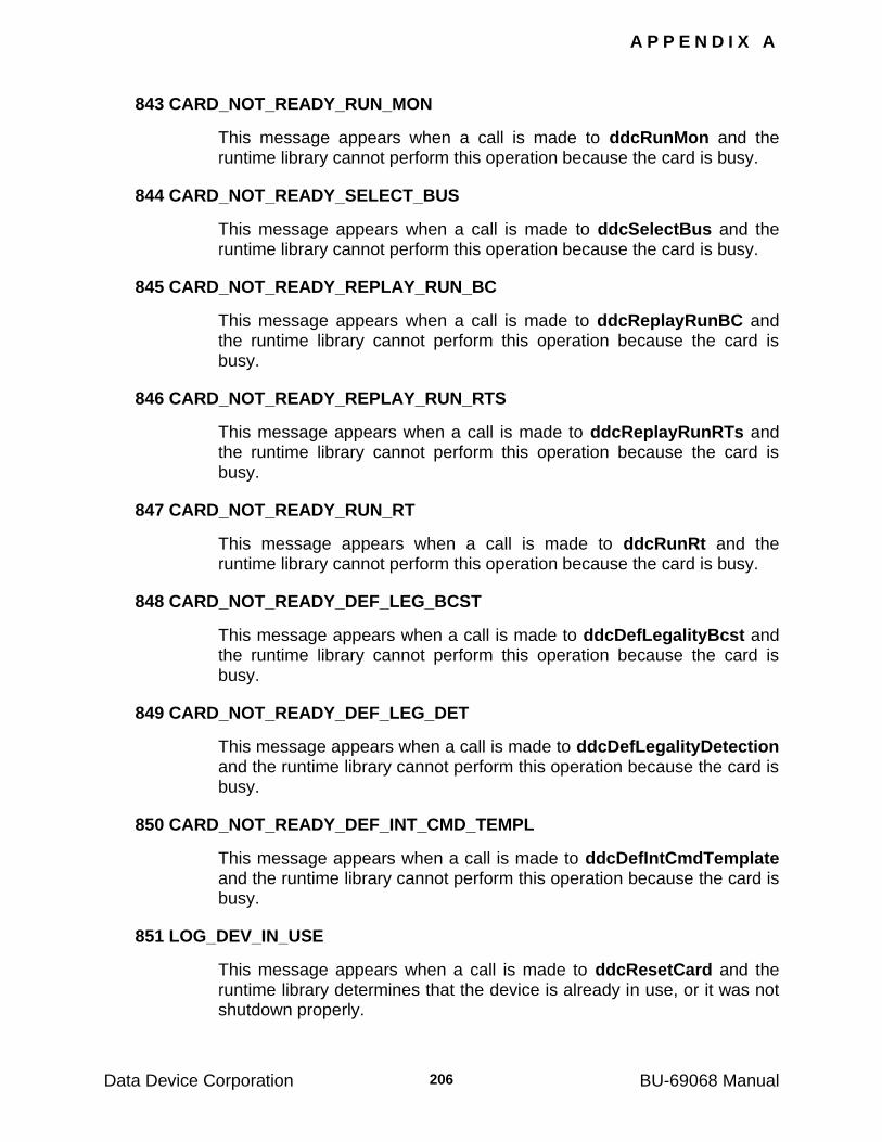
A P P E N D I X A
Data Device Corporation BU-69068 Manual 206
843 CARD_NOT_READY_RUN_MON
This message appears when a call is made to ddcRunMon and the runtime library cannot perform this operation because the card is busy.
844 CARD_NOT_READY_SELECT_BUS
This message appears when a call is made to ddcSelectBus and the runtime library cannot perform this operation because the card is busy.
845 CARD_NOT_READY_REPLAY_RUN_BC
This message appears when a call is made to ddcReplayRunBC and the runtime library cannot perform this operation because the card is busy.
846 CARD_NOT_READY_REPLAY_RUN_RTS
This message appears when a call is made to ddcReplayRunRTs and the runtime library cannot perform this operation because the card is busy.
847 CARD_NOT_READY_RUN_RT
This message appears when a call is made to ddcRunRt and the runtime library cannot perform this operation because the card is busy.
848 CARD_NOT_READY_DEF_LEG_BCST
This message appears when a call is made to ddcDefLegalityBcst and the runtime library cannot perform this operation because the card is busy.
849 CARD_NOT_READY_DEF_LEG_DET
This message appears when a call is made to ddcDefLegalityDetection and the runtime library cannot perform this operation because the card is busy.
850 CARD_NOT_READY_DEF_INT_CMD_TEMPL
This message appears when a call is made to ddcDefIntCmdTemplate and the runtime library cannot perform this operation because the card is busy.
851 LOG_DEV_IN_USE
This message appears when a call is made to ddcResetCard and the runtime library determines that the device is already in use, or it was not shutdown properly.
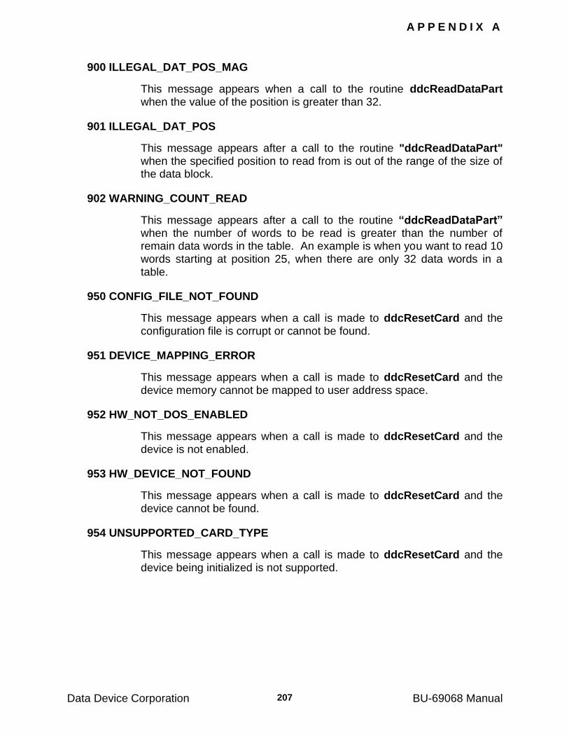
A P P E N D I X A
Data Device Corporation BU-69068 Manual 207
900 ILLEGAL_DAT_POS_MAG
This message appears when a call to the routine ddcReadDataPart when the value of the position is greater than 32.
901 ILLEGAL_DAT_POS
This message appears after a call to the routine "ddcReadDataPart" when the specified position to read from is out of the range of the size of the data block.
902 WARNING_COUNT_READ
This message appears after a call to the routine “ddcReadDataPart” when the number of words to be read is greater than the number of remain data words in the table. An example is when you want to read 10 words starting at position 25, when there are only 32 data words in a table.
950 CONFIG_FILE_NOT_FOUND
This message appears when a call is made to ddcResetCard and the configuration file is corrupt or cannot be found.
951 DEVICE_MAPPING_ERROR
This message appears when a call is made to ddcResetCard and the device memory cannot be mapped to user address space.
952 HW_NOT_DOS_ENABLED
This message appears when a call is made to ddcResetCard and the device is not enabled.
953 HW_DEVICE_NOT_FOUND
This message appears when a call is made to ddcResetCard and the device cannot be found.
954 UNSUPPORTED_CARD_TYPE
This message appears when a call is made to ddcResetCard and the device being initialized is not supported.
Data Device Corporation BU-69068 Manual
208
15 APPENDIX B
15.1 Interrupts
Both the BC/RT and the Monitor request interrupts to the PC. The IREQ vector is selected by the operating system during card installation. The interrupts are serviced by an interrupt handler which checks the interrupt source (BC/RT or Monitor). It then reads the interrupt vector from the BC/RT or Monitor shared memory calls the appropriate user routine
(defined using ddcSetMonEvent and ddcSetBcrtEvent), and then prepares the card for the next interrupt.
The user "mon_event_handler" has no arguments. The RTL interrupt handler passes two arguments to the user "bcrt_event_handler". The inputs are defined as follows:
U16BIT vector_type - the first word of the interrupt vector
U16BIT vector_parameter - the second word of the interrupt vector
The initialization of the PC's interrupt controller and the CPU's vector table is performed by the Device Driver.
The RTL can handle interrupts from more than one DDC card, provided
the user assigns separate service routines using "ddcSetMonEvent"
and ddcSetBcrtEvent.
15.2 Monitor Interrupts
The Monitor can request 2 types of interrupts:
an interrupt after each message
an interrupt after 1/3 of the Monitor's circular buffer has been filled (approximately 2K words).
Only one Monitor interrupt type may be enabled; bits 14 and 15 in the INTERRUPT MASK are used to enable/disable the interrupts.
If Monitor interrupts are enabled, then the Monitor will also issue an
interrupt when it is halted by ddcHaltMon or ddcHaltIdea. This interrupt can be used to read the "tail-end" of the card's circular buffer (see
routines ddcReadMonStack and ddcReadMonStackPart each time the Monitor requests an interrupt it increments a counter. If a similar counter is incremented by the user, its value can be compared to the card's counter in order to detect lost interrupts.
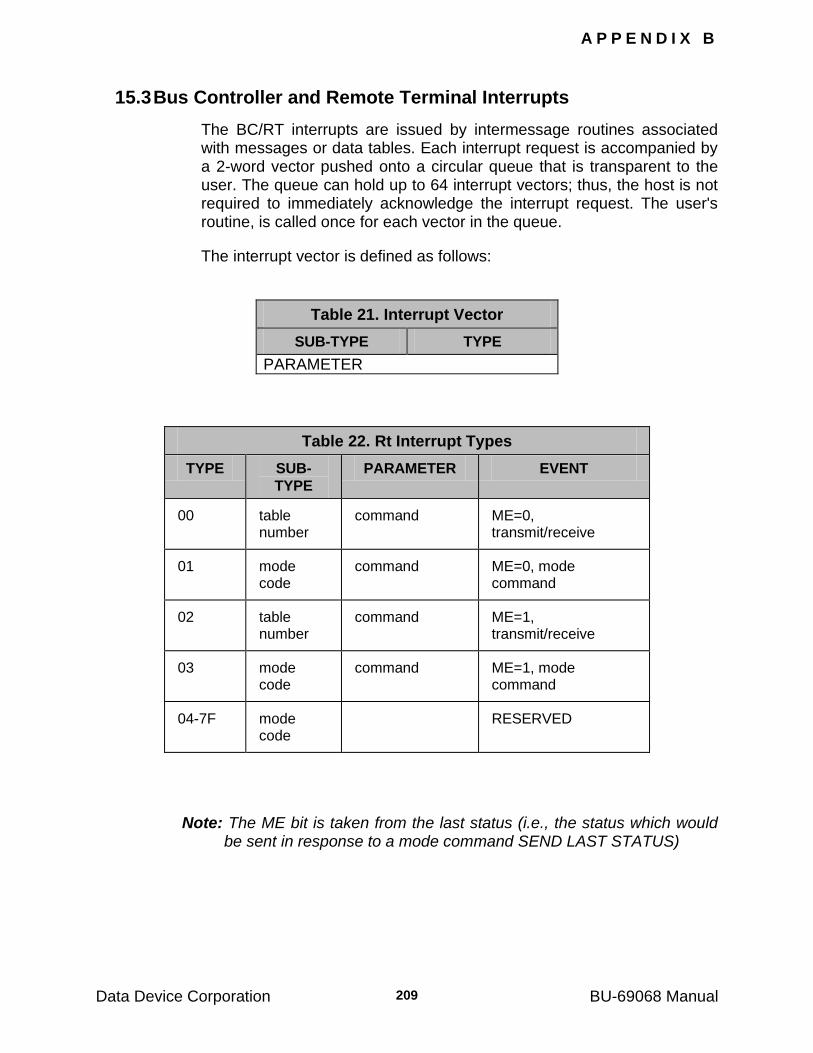
A P P E N D I X B
Data Device Corporation BU-69068 Manual 209
15.3 Bus Controller and Remote Terminal Interrupts
The BC/RT interrupts are issued by intermessage routines associated with messages or data tables. Each interrupt request is accompanied by a 2-word vector pushed onto a circular queue that is transparent to the user. The queue can hold up to 64 interrupt vectors; thus, the host is not required to immediately acknowledge the interrupt request. The user's routine, is called once for each vector in the queue.
The interrupt vector is defined as follows:
Table 21. Interrupt Vector
SUB-TYPE TYPE
PARAMETER
Table 22. Rt Interrupt Types
TYPE SUB-
TYPE
PARAMETER EVENT
00 table number
command ME=0, transmit/receive
01 mode code
command ME=0, mode command
02 table number
command ME=1, transmit/receive
03 mode code
command ME=1, mode command
04-7F mode code
RESERVED
Note: The ME bit is taken from the last status (i.e., the status which would be sent in response to a mode command SEND LAST STATUS)
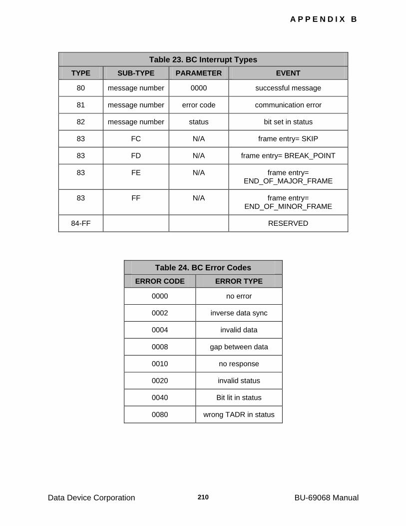
A P P E N D I X B
Data Device Corporation BU-69068 Manual 210
Table 23. BC Interrupt Types
TYPE SUB-TYPE PARAMETER EVENT
80 message number 0000 successful message
81 message number error code communication error
82 message number status bit set in status
83 FC N/A frame entry= SKIP
83 FD N/A frame entry= BREAK_POINT
83 FE N/A frame entry= END_OF_MAJOR_FRAME
83 FF N/A frame entry= END_OF_MINOR_FRAME
84-FF RESERVED
Table 24. BC Error Codes
ERROR CODE ERROR TYPE
0000 no error
0002 inverse data sync
0004 invalid data
0008 gap between data
0010 no response
0020 invalid status
0040 Bit lit in status
0080 wrong TADR in status

A P P E N D I X B
Data Device Corporation BU-69068 Manual 211
15.4 Interrupt Mask
The INTERRUPT MASK is a 16-bit word that resides in the BC/RT and Monitor shared memories. Each bit in the mask, when set to "1", inhibits a unique interrupt type.
Table 25. Interrupt Mask
MASK BIT INTERRUPT TYPE
0 00
1 01
2 02
3 03
4 80
5 81
6 82
7 83
8 XX
9 XX
10 XX
11 XX
12 XX
13 XX
14 1/3 of Circular Buffer (Monitor)
15 End of Msg (Monitor)
Data Device Corporation BU-69068 Manual
212
16 APPENDIX C
16.1 Intermessage Routines
During each intermessage gap, the BC/RT executes 2 INTERMESSAGE ROUTINES specified by the user. These routines are chosen from the supplied RTL and they can be assigned to:
Messages issued by the BC
Data tables accessed by emulated RT‘s
Mode commands executed by emulated RT‘s
The assignment is accomplished by calling routines ddcDefMessage,
ddcDefTableRoutine, and ddcDefModeRoutine. If a message is internal to the Tester/Simulator card (i.e., between an emulated BC and an emulated RT), the routine associated with the data table will be ignored. Also, if the card emulates both RT‘s in a RT-to-RT message and does not emulate the BC, only the transmitting RT executes the intermessage routines. The intermessage routines are downloaded to the card during the RESET process. The following table lists the routines.
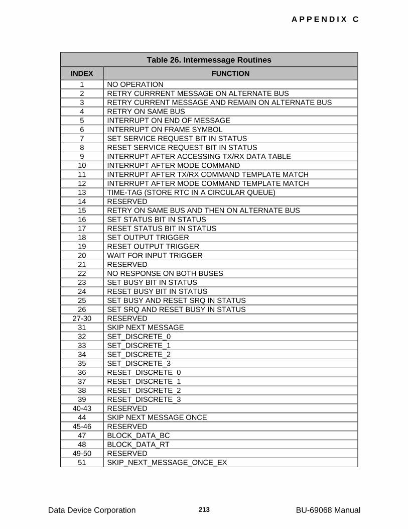
A P P E N D I X C
Data Device Corporation BU-69068 Manual 213
Table 26. Intermessage Routines
INDEX FUNCTION
1 NO OPERATION
2 RETRY CURRRENT MESSAGE ON ALTERNATE BUS
3 RETRY CURRENT MESSAGE AND REMAIN ON ALTERNATE BUS
4 RETRY ON SAME BUS
5 INTERRUPT ON END OF MESSAGE
6 INTERRUPT ON FRAME SYMBOL
7 SET SERVICE REQUEST BIT IN STATUS
8 RESET SERVICE REQUEST BIT IN STATUS
9 INTERRUPT AFTER ACCESSING TX/RX DATA TABLE
10 INTERRUPT AFTER MODE COMMAND
11 INTERRUPT AFTER TX/RX COMMAND TEMPLATE MATCH
12 INTERRUPT AFTER MODE COMMAND TEMPLATE MATCH
13 TIME-TAG (STORE RTC IN A CIRCULAR QUEUE)
14 RESERVED
15 RETRY ON SAME BUS AND THEN ON ALTERNATE BUS
16 SET STATUS BIT IN STATUS
17 RESET STATUS BIT IN STATUS
18 SET OUTPUT TRIGGER
19 RESET OUTPUT TRIGGER
20 WAIT FOR INPUT TRIGGER
21 RESERVED
22 NO RESPONSE ON BOTH BUSES
23 SET BUSY BIT IN STATUS
24 RESET BUSY BIT IN STATUS
25 SET BUSY AND RESET SRQ IN STATUS
26 SET SRQ AND RESET BUSY IN STATUS
27-30 RESERVED
31 SKIP NEXT MESSAGE
32 SET_DISCRETE_0
33 SET_DISCRETE_1
34 SET_DISCRETE_2
35 SET_DISCRETE_3
36 RESET_DISCRETE_0
37 RESET_DISCRETE_1
38 RESET_DISCRETE_2
39 RESET_DISCRETE_3
40-43 RESERVED
44 SKIP NEXT MESSAGE ONCE
45-46 RESERVED
47 BLOCK_DATA_BC
48 BLOCK_DATA_RT
49-50 RESERVED
51 SKIP_NEXT_MESSAGE_ONCE_EX
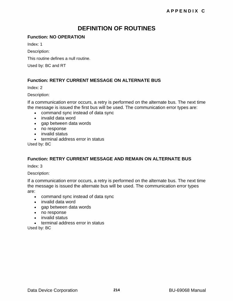
A P P E N D I X C
Data Device Corporation BU-69068 Manual 214
DEFINITION OF ROUTINES
Function: NO OPERATION
Index: 1
Description:
This routine defines a null routine.
Used by: BC and RT
Function: RETRY CURRENT MESSAGE ON ALTERNATE BUS
Index: 2
Description:
If a communication error occurs, a retry is performed on the alternate bus. The next time the message is issued the first bus will be used. The communication error types are:
command sync instead of data sync invalid data word gap between data words no response invalid status terminal address error in status
Used by: BC
Function: RETRY CURRENT MESSAGE AND REMAIN ON ALTERNATE BUS
Index: 3
Description:
If a communication error occurs, a retry is performed on the alternate bus. The next time the message is issued the alternate bus will be used. The communication error types are:
command sync instead of data sync invalid data word gap between data words no response invalid status terminal address error in status
Used by: BC
A P P E N D I X C
Data Device Corporation BU-69068 Manual 215
Function: RETRY ON SAME BUS
Index: 4
Description:
If a communication error occurs, a retry is performed on the same bus. The communication error types are:
command sync instead of data sync invalid data word gap between data words no response invalid status terminal address error in status
Used by: BC
Function: INTERRUPT ON END OF MESSAGE
Index: 5
Description:
An interrupt is issued to the host (provided the request is not masked) at the end of message. The interrupt vector indicates whether or not there was a communication error or a bit set in the status. Used by: BC
Function: INTERRUPT ON FRAME SYMBOL
Index: 6
Description:
An interrupt is issued to the host (provided the request is not masked) when at the end of the message the following symbols appear in the communication FRAME (provided the routine is assigned to the symbol by ddcDefMessage) :
SKIP BREAK POINT END OF MINOR FRAME END OF MAJOR FRAME
Used by: BC
A P P E N D I X C
Data Device Corporation BU-69068 Manual 216
Function: SET THE SERVICE REQUEST BIT IN STATUS
Index: 7
Description:
This routine sets the service request bit in the basic status of the RT which responded to the last command. Used by: BC and RT
Function: RESET THE SERVICE REQUEST BIT IN STATUS
Index: 8
Description:
This routine resets the service request bit in the basic status of the RT that responded to the last command. Used by: BC and RT
Function: INTERRUPT AFTER ACCESSING TX/RX DATA TABLE
Index: 9
Description:
An interrupt is issued to the host (provided the request is not masked) after an emulated RT accesses a data table associated with a transmit/receive command. The vector pushed onto the interrupt request queue defines:
the value of the ME bit in the status data table number command word
The type field in the interrupt vector equals 0 or 2. Used by: RT (for TX/RX messages only)
Function: INTERRUPT AFTER MODE COMMANDS
Index: 10
Description:
An interrupt is issued to the host (provided the request is not masked) after an emulated RT receives a mode command. The vector pushed onto the interrupt request queue defines:
the value of the ME bit in the status mode code command word
The type field in the interrupt vector equals 1 or 3. Used by: RT (for mode commands only)
A P P E N D I X C
Data Device Corporation BU-69068 Manual 217
Function: INTERRUPT AFTER TX/RX COMMAND TEMPLATE MATCH
Index: 11
Description:
An interrupt is issued to the host (provided the request is not masked) after an emulated RT accesses a data table associated with a transmit/receive command which matches a template as follows:
cmpwd = command AND maskwd. The compare word (cmpwd) and mask word (maskwd) are defined by the RTL routine ddcDefIntCmdTemplate. The type field in the interrupt vector equals 0 or 2. Used by: RT (for TX/RX messages only)
Function: INTERRUPT AFTER MODE COMMAND TEMPLATE MATCH
Index: 12
Description:
An interrupt is issued to the host (provided the request is not masked) after an emulated RT executes a mode command that matches a template as follows: cmpwd = command AND maskwd. The compare word (cmpwd) and mask word (maskwd) are defined by the RTL routine
ddcDefIntCmdTemplate. The type field in the interrupt vector equals 1 or 3. Used by: RT (for mode commands only)
Function: TIME-TAG
Index: 13
Description:
The 32 bit Real-Time-Clock of the BCRT is stored in a circular queue which contains up to 64 time tags. The time has a resolution of 1 microseconds and a maximum sampling inaccuracy of ±1 microsecond. Used by: RT
A P P E N D I X C
Data Device Corporation BU-69068 Manual 218
Function: RETRY ON SAME BUS AND THEN ON ALTERNATE BUS
Index: 15
Description:
If a communication error occurs, a retry is performed on the same bus. If the communication is still unsuccessful, a second retry will be performed on the alternate bus. Subsequent messages will remain on the alternate bus. The communication error types are:
command sync instead of data sync invalid data word gap between data words no response invalid status terminal address error in status
Used by: BC
Function: SET STATUS BIT IN STATUS
Index: 16
Description:
This routine sets the terminal flag bit in the basic status of the RT that responded to the last command. Used by: BC
Function: RESET STATUS BIT IN STATUS
Index: 17
Description:
This routine resets the terminal flag bit in the basic status of the RT that responded to the last command. Used by: BC
Function: SET OUTPUT TRIGGER
Index: 18
Description:
This routine sets the BC Output Trigger on the D-type connector to logic "1".
Note: This pin is also used for START OF FRAME.
Used by: BC and RT
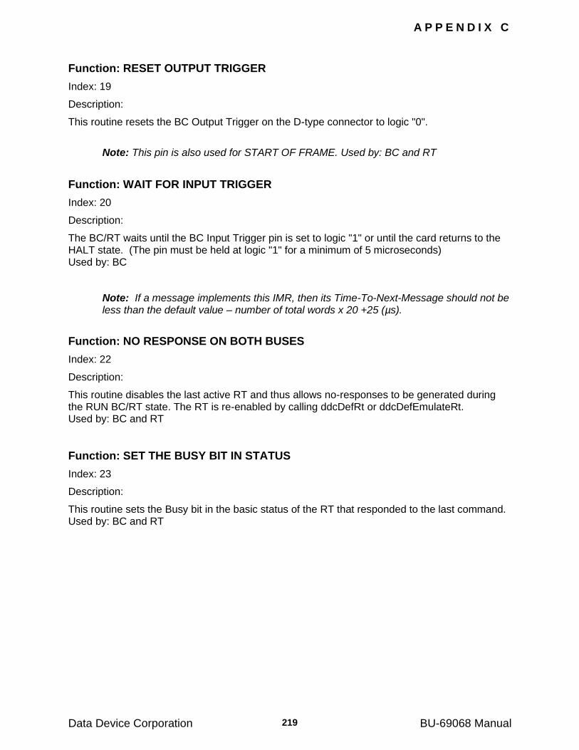
A P P E N D I X C
Data Device Corporation BU-69068 Manual 219
Function: RESET OUTPUT TRIGGER
Index: 19
Description:
This routine resets the BC Output Trigger on the D-type connector to logic "0".
Note: This pin is also used for START OF FRAME. Used by: BC and RT
Function: WAIT FOR INPUT TRIGGER
Index: 20
Description:
The BC/RT waits until the BC Input Trigger pin is set to logic "1" or until the card returns to the HALT state. (The pin must be held at logic "1" for a minimum of 5 microseconds) Used by: BC
Note: If a message implements this IMR, then its Time-To-Next-Message should not be less than the default value – number of total words x 20 +25 (µs).
Function: NO RESPONSE ON BOTH BUSES
Index: 22
Description:
This routine disables the last active RT and thus allows no-responses to be generated during the RUN BC/RT state. The RT is re-enabled by calling ddcDefRt or ddcDefEmulateRt. Used by: BC and RT
Function: SET THE BUSY BIT IN STATUS
Index: 23
Description:
This routine sets the Busy bit in the basic status of the RT that responded to the last command. Used by: BC and RT
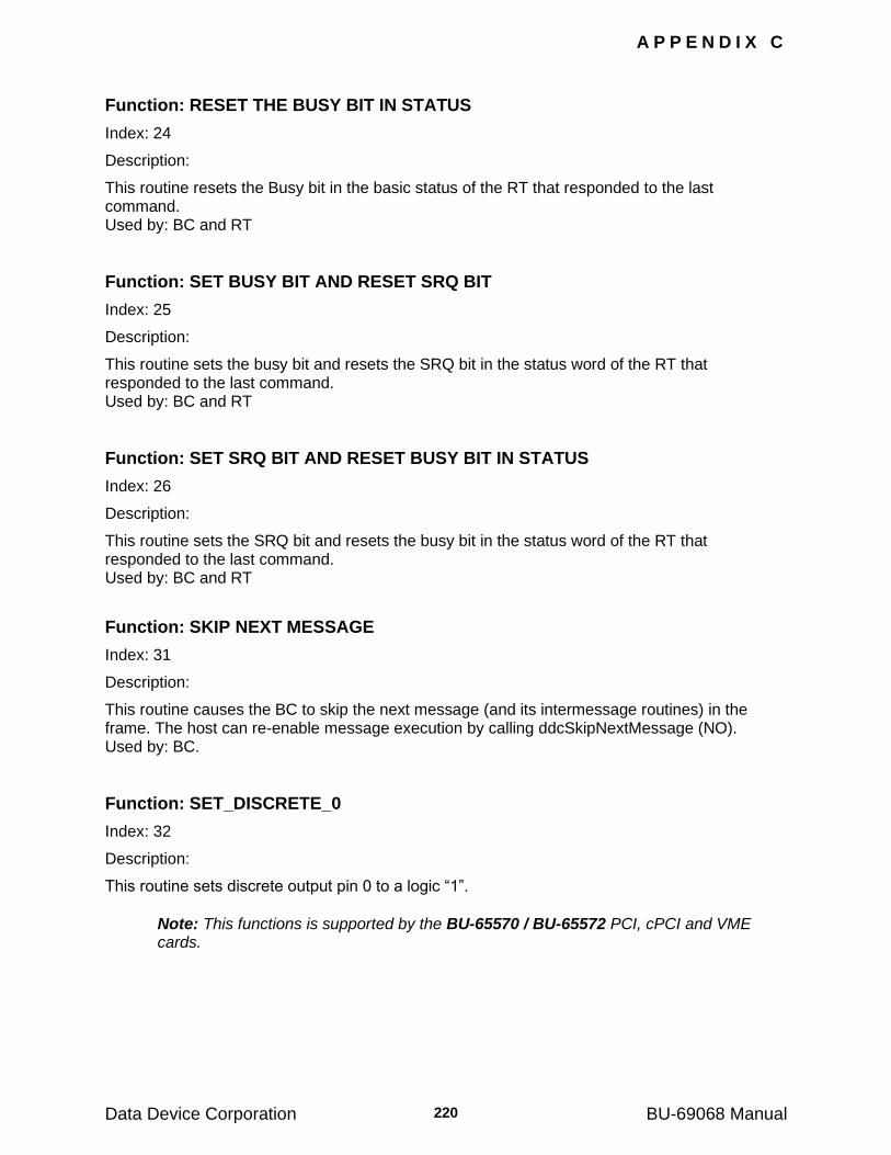
A P P E N D I X C
Data Device Corporation BU-69068 Manual 220
Function: RESET THE BUSY BIT IN STATUS
Index: 24
Description:
This routine resets the Busy bit in the basic status of the RT that responded to the last command. Used by: BC and RT
Function: SET BUSY BIT AND RESET SRQ BIT
Index: 25
Description:
This routine sets the busy bit and resets the SRQ bit in the status word of the RT that responded to the last command. Used by: BC and RT
Function: SET SRQ BIT AND RESET BUSY BIT IN STATUS
Index: 26
Description:
This routine sets the SRQ bit and resets the busy bit in the status word of the RT that responded to the last command. Used by: BC and RT
Function: SKIP NEXT MESSAGE
Index: 31
Description:
This routine causes the BC to skip the next message (and its intermessage routines) in the frame. The host can re-enable message execution by calling ddcSkipNextMessage (NO). Used by: BC.
Function: SET_DISCRETE_0
Index: 32
Description:
This routine sets discrete output pin 0 to a logic ―1‖.
Note: This functions is supported by the BU-65570 / BU-65572 PCI, cPCI and VME cards.
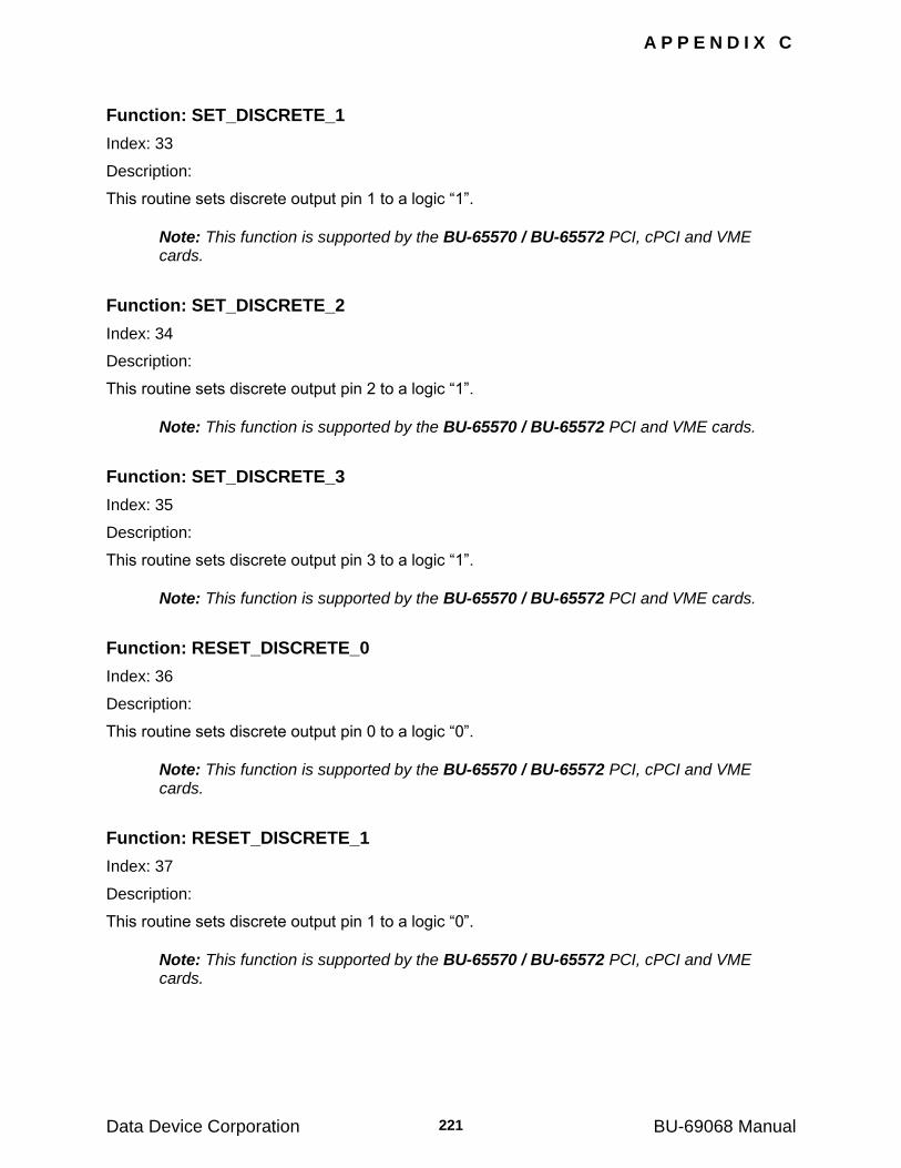
A P P E N D I X C
Data Device Corporation BU-69068 Manual 221
Function: SET_DISCRETE_1
Index: 33
Description:
This routine sets discrete output pin 1 to a logic ―1‖.
Note: This function is supported by the BU-65570 / BU-65572 PCI, cPCI and VME cards.
Function: SET_DISCRETE_2
Index: 34
Description:
This routine sets discrete output pin 2 to a logic ―1‖.
Note: This function is supported by the BU-65570 / BU-65572 PCI and VME cards.
Function: SET_DISCRETE_3
Index: 35
Description:
This routine sets discrete output pin 3 to a logic ―1‖.
Note: This function is supported by the BU-65570 / BU-65572 PCI and VME cards.
Function: RESET_DISCRETE_0
Index: 36
Description:
This routine sets discrete output pin 0 to a logic ―0‖.
Note: This function is supported by the BU-65570 / BU-65572 PCI, cPCI and VME cards.
Function: RESET_DISCRETE_1
Index: 37
Description:
This routine sets discrete output pin 1 to a logic ―0‖.
Note: This function is supported by the BU-65570 / BU-65572 PCI, cPCI and VME cards.
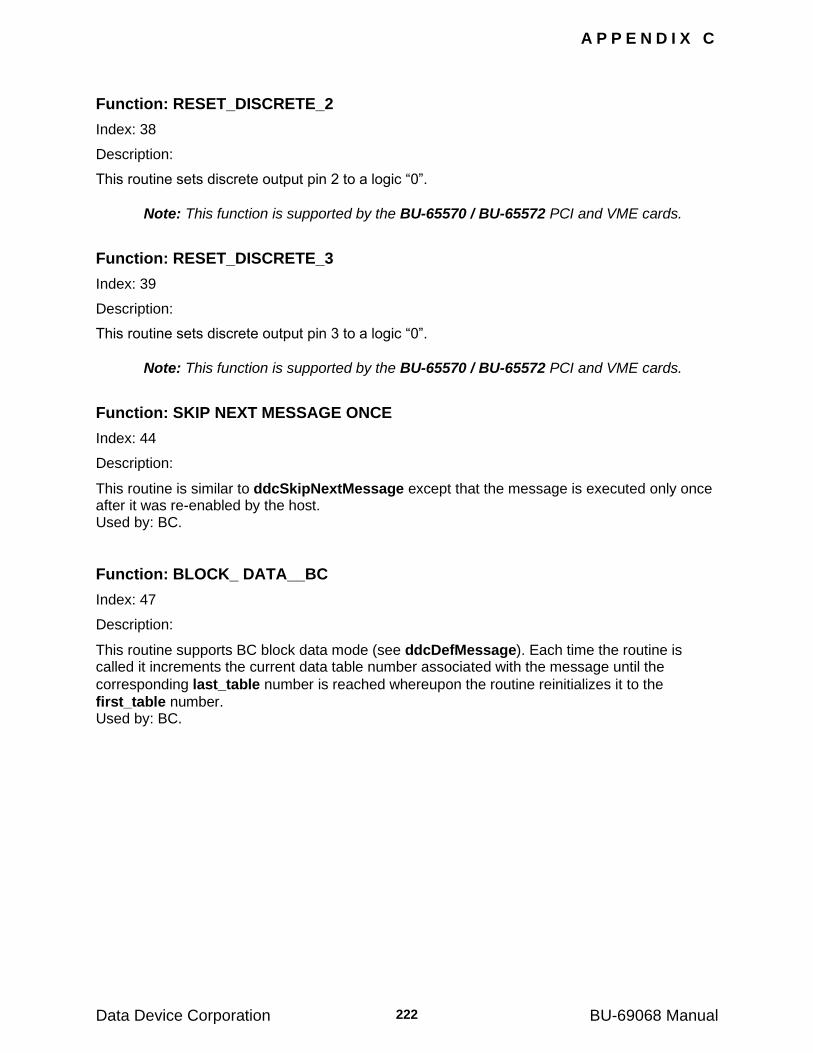
A P P E N D I X C
Data Device Corporation BU-69068 Manual 222
Function: RESET_DISCRETE_2
Index: 38
Description:
This routine sets discrete output pin 2 to a logic ―0‖.
Note: This function is supported by the BU-65570 / BU-65572 PCI and VME cards.
Function: RESET_DISCRETE_3
Index: 39
Description:
This routine sets discrete output pin 3 to a logic ―0‖.
Note: This function is supported by the BU-65570 / BU-65572 PCI and VME cards.
Function: SKIP NEXT MESSAGE ONCE
Index: 44
Description:
This routine is similar to ddcSkipNextMessage except that the message is executed only once after it was re-enabled by the host. Used by: BC.
Function: BLOCK_ DATA__BC
Index: 47
Description:
This routine supports BC block data mode (see ddcDefMessage). Each time the routine is called it increments the current data table number associated with the message until the
corresponding last_table number is reached whereupon the routine reinitializes it to the
first_table number. Used by: BC.
A P P E N D I X C
Data Device Corporation BU-69068 Manual 223
Function: BLOCK_ DATA_RT
Index: 48
Description:
This routine supports RT block data mode (see ddcDefRtMapBlock). Each time the routine is called it increments the current data table number associated with the command until the
corresponding last_table number is reached whereupon the routine reinitializes it to the
first_table number. Used by: RT.
Function: SKIP_NEXT_MESSAGE_ONCE_EX
Index: 51
Description:
With this routine the message is only skipped once, and sent by the BC the rest of the time. The message is skipped only once after the IMR was re-enabled by the host. Used by: BC.
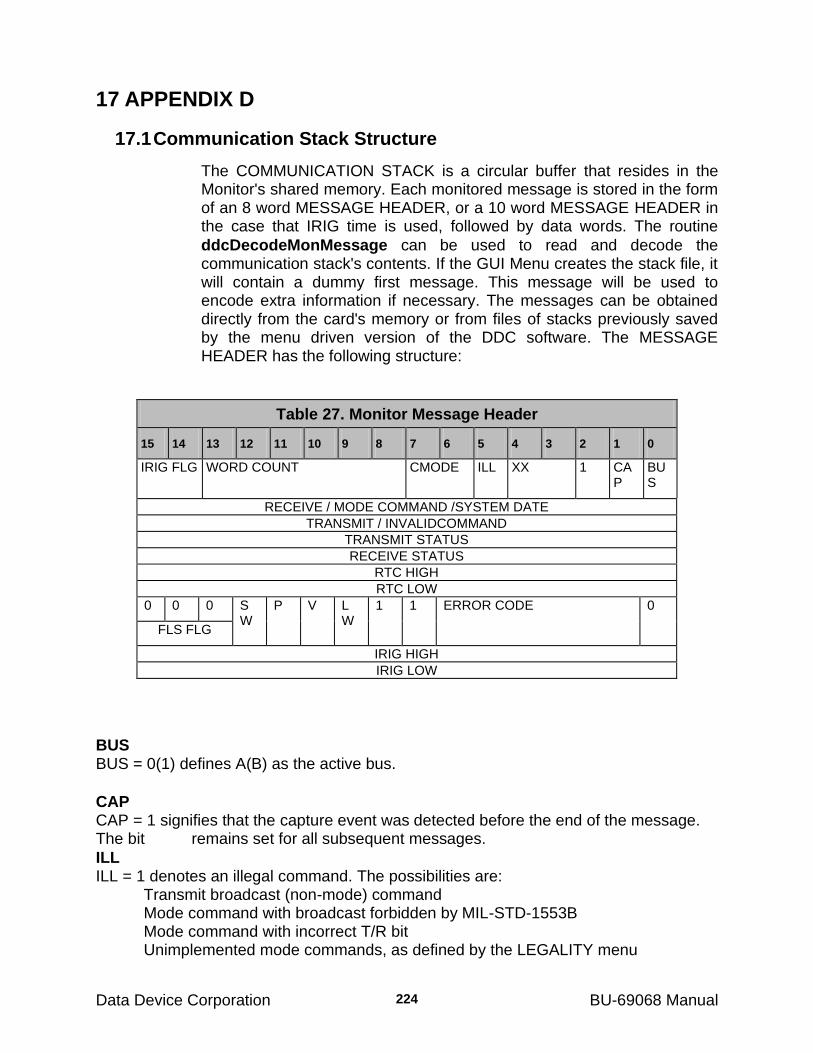
Data Device Corporation BU-69068 Manual
224
17 APPENDIX D
17.1 Communication Stack Structure
The COMMUNICATION STACK is a circular buffer that resides in the Monitor's shared memory. Each monitored message is stored in the form of an 8 word MESSAGE HEADER, or a 10 word MESSAGE HEADER in the case that IRIG time is used, followed by data words. The routine
ddcDecodeMonMessage can be used to read and decode the communication stack's contents. If the GUI Menu creates the stack file, it will contain a dummy first message. This message will be used to encode extra information if necessary. The messages can be obtained directly from the card's memory or from files of stacks previously saved by the menu driven version of the DDC software. The MESSAGE HEADER has the following structure:
Table 27. Monitor Message Header
15 14 13 12 11 10 9 8 7 6 5 4 3 2 1 0
IRIG FLG WORD COUNT CMODE ILL XX 1 CAP
BUS
RECEIVE / MODE COMMAND /SYSTEM DATE
TRANSMIT / INVALIDCOMMAND
TRANSMIT STATUS
RECEIVE STATUS
RTC HIGH
RTC LOW
0 0 0 SW
P V LW
1 1 ERROR CODE 0
FLS FLG
IRIG HIGH
IRIG LOW
BUS BUS = 0(1) defines A(B) as the active bus.
CAP CAP = 1 signifies that the capture event was detected before the end of the message. The bit remains set for all subsequent messages.
ILL ILL = 1 denotes an illegal command. The possibilities are:
Transmit broadcast (non-mode) command Mode command with broadcast forbidden by MIL-STD-1553B Mode command with incorrect T/R bit Unimplemented mode commands, as defined by the LEGALITY menu
A P P E N D I X E
Data Device Corporation BU-69068 Manual 225
CMODE CMODE defines the message type. The possibilities are:
00 - Mode command 01 - Receive 10 - Transmit 11 - RT to RT
WORD COUNT WORD COUNT defines the actual number of data words in the message stored in the circular buffer. The field contains 6 bits; values 0 and 32 appear as 000000 and 100000 respectively.
IRIG FLG If IRIG is enabled for the monitor session, then this value will be ‗02‘b. At all other times this value is ‗00‘b. If IRIG is enabled, words 9 and 10 will be present.
RECEIVE/MODE COMMAND/SYSTEM DATE This word contains valid RECEIVE or MODE commands. If the message encodes IRIG and the stack file is a *.FLS GUI Menu generated stack file, then the first message in the stack is a dummy message. This dummy message will contain the computers system date as recorded when the stack file was created. This will allow a stack file (FLS) to be referenced to a year as well as month, day and second.
TRANSMIT/INVALIDCOMMAND This word contains TRANSMIT or INVALID commands.
TRANSMIT STATUS This word contains the STATUS word belonging to a command with T/R=1.
RECEIVE STATUS This word contains the STATUS word belonging to a command with T/R=0.
RTC HIGH This word contains the most significant 16 bits of the time tag.
RTC LOW This word contains the least significant 16 bits of the time tag. The resolution is 1 microsecond.
ERROR CODE The ERROR CODE is a 6 bit field with the values given in Table 30.
LW LW = 1 denotes that there was a long word error (time between successive syncs greater than 21 microseconds) in the second to last monitored data word.
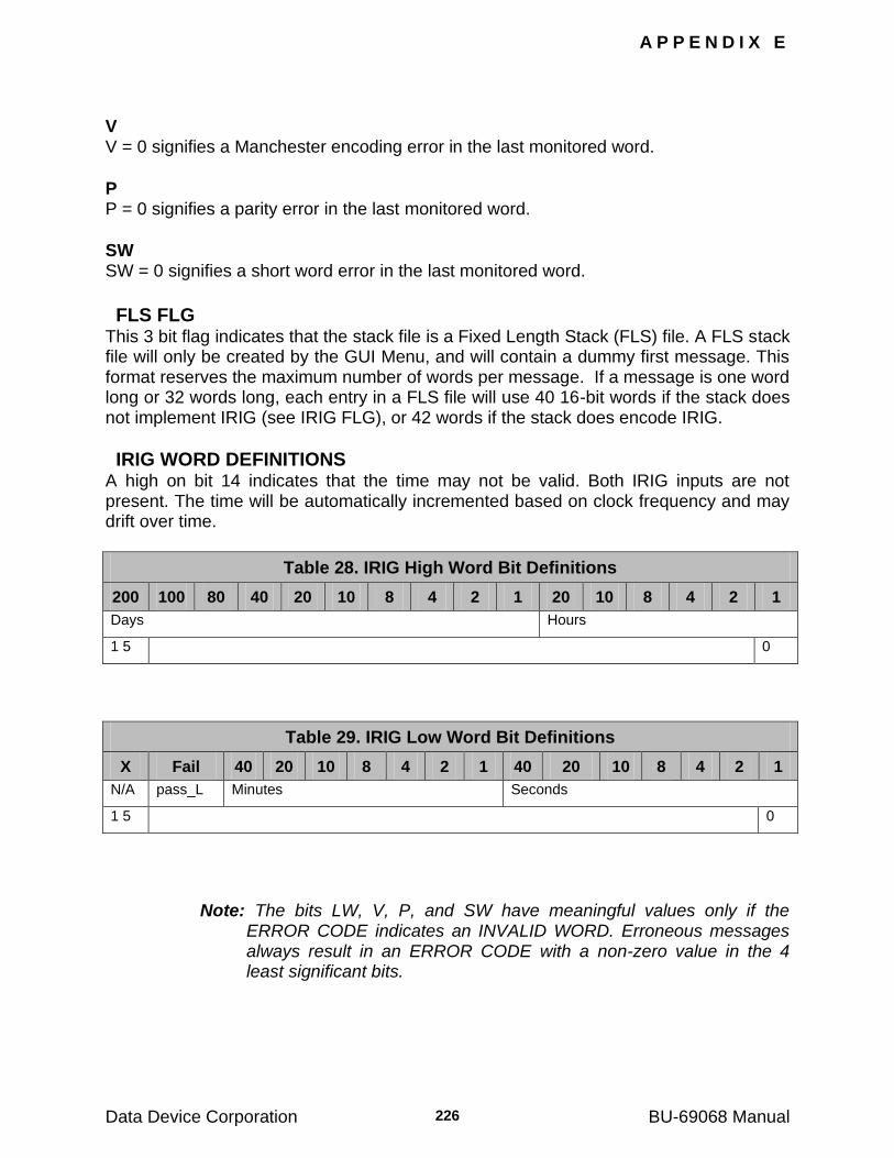
A P P E N D I X E
Data Device Corporation BU-69068 Manual 226
V V = 0 signifies a Manchester encoding error in the last monitored word.
P P = 0 signifies a parity error in the last monitored word.
SW SW = 0 signifies a short word error in the last monitored word.
FLS FLG This 3 bit flag indicates that the stack file is a Fixed Length Stack (FLS) file. A FLS stack file will only be created by the GUI Menu, and will contain a dummy first message. This format reserves the maximum number of words per message. If a message is one word long or 32 words long, each entry in a FLS file will use 40 16-bit words if the stack does not implement IRIG (see IRIG FLG), or 42 words if the stack does encode IRIG.
IRIG WORD DEFINITIONS A high on bit 14 indicates that the time may not be valid. Both IRIG inputs are not present. The time will be automatically incremented based on clock frequency and may drift over time.
Table 28. IRIG High Word Bit Definitions
200 100 80 40 20 10 8 4 2 1 20 10 8 4 2 1
Days Hours
1 5 0
Table 29. IRIG Low Word Bit Definitions
X Fail 40 20 10 8 4 2 1 40 20 10 8 4 2 1
N/A pass_L Minutes Seconds
1 5 0
Note: The bits LW, V, P, and SW have meaningful values only if the ERROR CODE indicates an INVALID WORD. Erroneous messages always result in an ERROR CODE with a non-zero value in the 4 least significant bits.
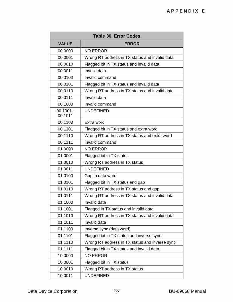
A P P E N D I X E
Data Device Corporation BU-69068 Manual 227
Table 30. Error Codes
VALUE ERROR
00 0000 NO ERROR
00 0001 Wrong RT address in TX status and invalid data
00 0010 Flagged bit in TX status and invalid data
00 0011 Invalid data
00 0100 Invalid command
00 0101 Flagged bit in TX status and invalid data
00 0110 Wrong RT address in TX status and invalid data
00 0111 Invalid data
00 1000 Invalid command
00 1001 - 00 1011
UNDEFINED
00 1100 Extra word
00 1101 Flagged bit in TX status and extra word
00 1110 Wrong RT address in TX status and extra word
00 1111 Invalid command
01 0000 NO ERROR
01 0001 Flagged bit in TX status
01 0010 Wrong RT address in TX status
01 0011 UNDEFINED
01 0100 Gap in data word
01 0101 Flagged bit in TX status and gap
01 0110 Wrong RT address in TX status and gap
01 0111 Wrong RT address in TX status and invalid data
01 1000 Invalid data
01 1001 Flagged in TX status and invalid data
01 1010 Wrong RT address in TX status and invalid data
01 1011 Invalid data
01 1100 Inverse sync (data word)
01 1101 Flagged bit in TX status and inverse sync
01 1110 Wrong RT address in TX status and inverse sync
01 1111 Flagged bit in TX status and invalid data
10 0000 NO ERROR
10 0001 Flagged bit in TX status
10 0010 Wrong RT address in TX status
10 0011 UNDEFINED
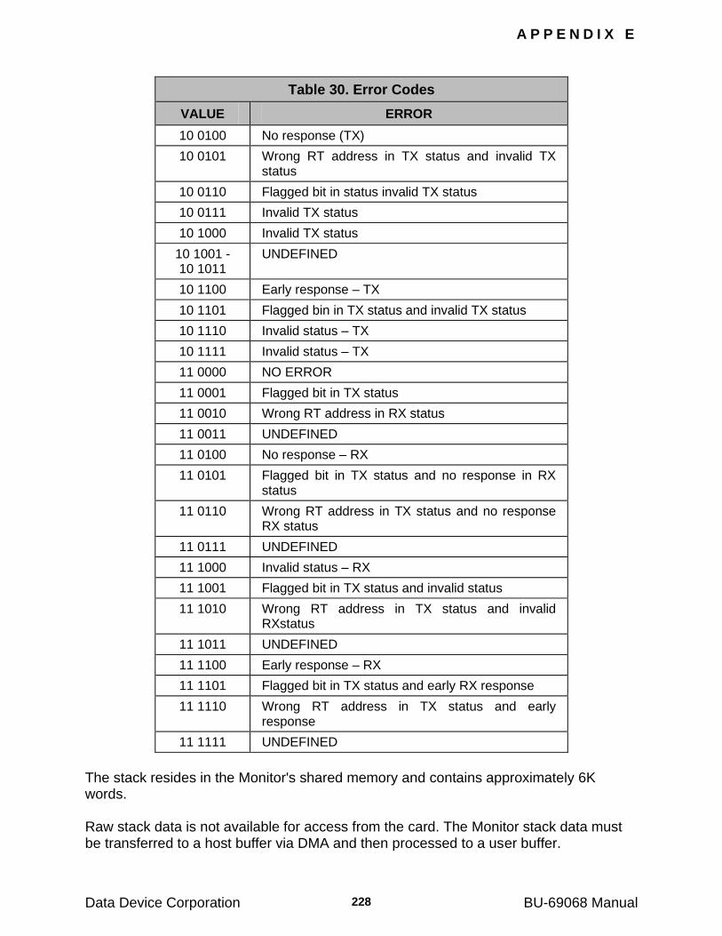
A P P E N D I X E
Data Device Corporation BU-69068 Manual 228
Table 30. Error Codes
VALUE ERROR
10 0100 No response (TX)
10 0101 Wrong RT address in TX status and invalid TX status
10 0110 Flagged bit in status invalid TX status
10 0111 Invalid TX status
10 1000 Invalid TX status
10 1001 - 10 1011
UNDEFINED
10 1100 Early response – TX
10 1101 Flagged bin in TX status and invalid TX status
10 1110 Invalid status – TX
10 1111 Invalid status – TX
11 0000 NO ERROR
11 0001 Flagged bit in TX status
11 0010 Wrong RT address in RX status
11 0011 UNDEFINED
11 0100 No response – RX
11 0101 Flagged bit in TX status and no response in RX status
11 0110 Wrong RT address in TX status and no response RX status
11 0111 UNDEFINED
11 1000 Invalid status – RX
11 1001 Flagged bit in TX status and invalid status
11 1010 Wrong RT address in TX status and invalid RXstatus
11 1011 UNDEFINED
11 1100 Early response – RX
11 1101 Flagged bit in TX status and early RX response
11 1110 Wrong RT address in TX status and early response
11 1111 UNDEFINED
The stack resides in the Monitor's shared memory and contains approximately 6K words. Raw stack data is not available for access from the card. The Monitor stack data must be transferred to a host buffer via DMA and then processed to a user buffer.
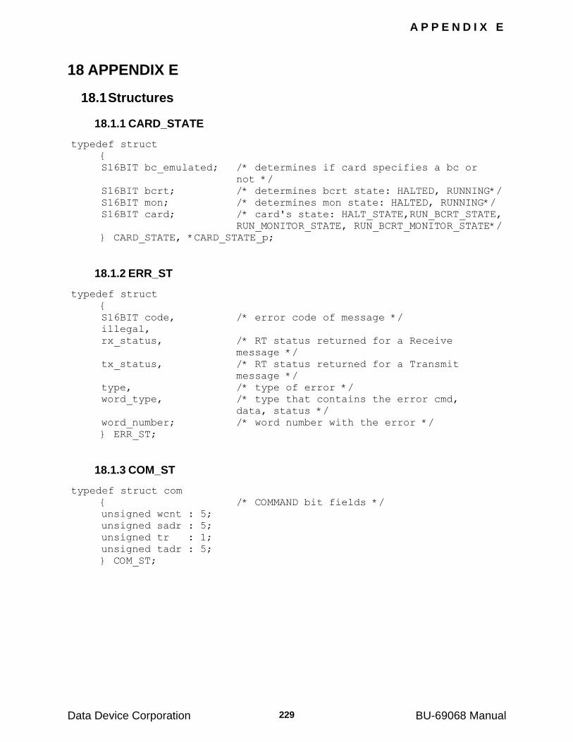
A P P E N D I X E
Data Device Corporation BU-69068 Manual 229
18 APPENDIX E
18.1 Structures
18.1.1 CARD_STATE
typedef struct
{
S16BIT bc_emulated; /* determines if card specifies a bc or
not */
S16BIT bcrt; /* determines bcrt state: HALTED, RUNNING*/
S16BIT mon; /* determines mon state: HALTED, RUNNING*/
S16BIT card; /* card's state: HALT_STATE,RUN_BCRT_STATE,
RUN_MONITOR_STATE, RUN_BCRT_MONITOR_STATE*/
} CARD_STATE, *CARD_STATE_p;
18.1.2 ERR_ST
typedef struct
{
S16BIT code, /* error code of message */
illegal,
rx_status, /* RT status returned for a Receive
message */
tx_status, /* RT status returned for a Transmit
message */
type, /* type of error */
word_type, /* type that contains the error cmd,
data, status */
word_number; /* word number with the error */
} ERR_ST;
18.1.3 COM_ST
typedef struct com
{ /* COMMAND bit fields */
unsigned wcnt : 5;
unsigned sadr : 5;
unsigned tr : 1;
unsigned tadr : 5;
} COM_ST;
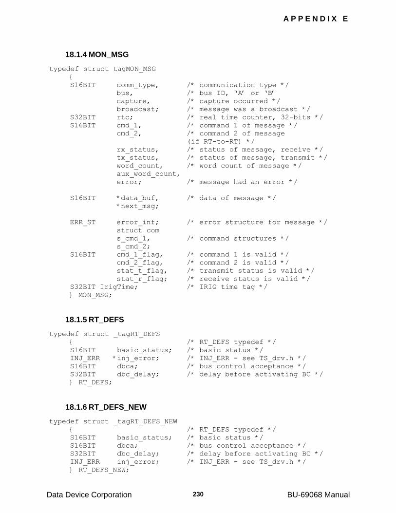
A P P E N D I X E
Data Device Corporation BU-69068 Manual 230
18.1.4 MON_MSG
typedef struct tagMON_MSG
{
S16BIT comm_type, /* communication type */
bus, /* bus ID, „A‟ or „B‟
capture, /* capture occurred */
broadcast; /* message was a broadcast */
S32BIT rtc; /* real time counter, 32-bits */
S16BIT cmd_1, /* command 1 of message */
cmd_2, /* command 2 of message
(if RT-to-RT) */
rx_status, /* status of message, receive */
tx_status, /* status of message, transmit */
word_count, /* word count of message */
aux_word_count,
error; /* message had an error */
S16BIT *data_buf, /* data of message */
*next_msg;
ERR_ST error_inf; /* error structure for message */
struct com
s_cmd_1, /* command structures */
s_cmd_2;
S16BIT cmd_1_flag, /* command 1 is valid */
cmd_2_flag, /* command 2 is valid */
stat_t_flag, /* transmit status is valid */
stat_r_flag; /* receive status is valid */
S32BIT IrigTime; /* IRIG time tag */
} MON_MSG;
18.1.5 RT_DEFS
typedef struct _tagRT_DEFS
{ /* RT_DEFS typedef */
S16BIT basic_status; /* basic status */
INJ_ERR *inj_error; /* INJ_ERR - see TS_drv.h */
S16BIT dbca; /* bus control acceptance */
S32BIT dbc_delay; /* delay before activating BC */
} RT_DEFS;
18.1.6 RT_DEFS_NEW
typedef struct _tagRT_DEFS_NEW
{ /* RT_DEFS typedef */
S16BIT basic_status; /* basic status */
S16BIT dbca; /* bus control acceptance */
S32BIT dbc_delay; /* delay before activating BC */
INJ_ERR inj_error; /* INJ_ERR - see TS_drv.h */
} RT_DEFS_NEW;
Data Device Corporation BU-69068 Manual
231
19 APPENDIX F
19.1 Compiler issues: Microsoft Visual C++ vs. Borland
The Tester Simulator RTL was created for use under various compiler environments, with the default environment being MSVC 5 and MSVC 6. The Tester Simulator RTL Dynamic Link Library (TestSim32.dll) is build to utilize the ―Standard call‖ calling convention and has its structure member alignment set at Quad word (8-byte).
When compiling a software application using MSVC, the steps are generally simple when creating your program and have it dynamically linked to our RTL. This process begins by insuring your project source includes ―TS_drv.h‖ (the main Test and Simulation header file). Your project workspace must also include the TestSim32.lib library file. When compiling, TestSim32.lib provides the necessary entry points into the TestSim32.dll. Your executable program will now reference our TestSim32.dll for any necessary RTL functions.
When using a Borland compiler environment the TestSim32.lib library file can not be linked to directly. An ―import library‖ application must be called to create a Borland type .lib file. This is done by using the implib.exe application supplied with the Borland compiler.
The following details apply when using the Tester Simulator RTL under a Borland compiler environment. Different rules apply when using Borland Builder vs. Borland C++ Suite 5.0x:
19.1.1 BORLAND BUILDER:
This compiler environment generally carries the same calling convention and structure member alignment as used in MSVC. This allows the developer to build and link to the standard Tester Simulator dynamic link library (TestSim32.dll).
1. Create your new project workspace, adding in any necessary source modules.
2. Make sure the source module referencing any Tester Simulator RTL functions has the include for ―TS_drv.h‖ (the main Test and Simulation header file).
3. Add the Tester Simulator Include path into the compiler include path settings.
4. From a command line prompt call the Borland implib.exe application. This application will create a .lib file that will allow you
A P P E N D I X F
Data Device Corporation BU-69068 Manual 232
to link your project to our dll. To extract the necessary .dll entry points you must run implib.exe against the ―TestSim32.dll‖ file that installed with the TestSim RTL. TestSim32.dll is generally located in the \WINDOWS\system32 directory. Perform a search to locate this file before attempting to run implib.exe. The following is an example of how to use implib.exe:
implib TestSimBorlandBuilder.lib TestSim32.dll
This command will result in the ―TestSimBorlandBuilder.lib‖ file being created to include all TestSim32.dll entry points.
5. You can now include the ―TestSimBorlandBuilder.lib‖ file into your project workspace. This will allow you to compile and link your application to the TestSim32.dll dynamic link library.
19.1.2 BORLAND C++ SUITE 5.0x:
This compiler environment generally uses a different calling convention and structure member alignment than that used in MSVC. This requires the developer to build and link to a special version of the Tester Simulator dynamic link library (TestSim32bs5.dll).
1. Create your new project workspace, adding in any necessary source modules.
2. You will need to be sure the project calling convention is set to ―Standard call‖. This can be done by accessing Borland Suite‘s Toolbar menu. Configure this option by selecting Options -> Project, and then select the 32-bit Compiler settings -> Calling convention selection.
3. Add the Tester Simulator Include path into the compiler include path settings.
4. Make sure the source module referencing any Tester Simulator RTL functions has the include for ―TS_drv.h‖ (the main Test and Simulation header file).
5. From a command line prompt, call the Borland implib.exe application. This application will create a .lib file that will allow you to link your project against. To extract the necessary .dll entry points you must run implib.exe against the ―TestSim32bs5.dll‖ file that installed with the TestSim RTL. TestSim32bs5.dll is generally located in the \WINDOWS\system32 directory. Perform a search to locate this file before attempting to run implib.exe. The following is an example of how to use implib.exe:
A P P E N D I X F
Data Device Corporation BU-69068 Manual 233
implib TestSimBorlandSuite.lib TestSim32bs5.dll
This command will result in the ―TestSimBorlandSuite.lib‖ file being created to include all TestSim32bs5.dll entry points.
6. You can now include the ―TestSimBorlandSuite.lib‖ file into your project workspace. This will allow you to compile and link your application to the TestSim32bs5.dll dynamic link library.
Data Device Corporation BU-69068 Manual
234
20 APPENDIX G
20.1 Using the LabWindows™/CVI Software
This section will explain the examples that are included in this software library for use with LabWindows/CVI. This appendix does not teach the user about LabWindows/CVI nor does it teach the user how to program.
20.1.1 Header Files
20.1.1.1 Types and Structure Definitions
The library header files are all included within the ―TesterSimulator.h‖. This file will include all of the other necessary header files to program the Tester/Simulator library.
20.1.2 Running Projects
There are five project files included with this software package to allow the user to run example programs as well as the front panel definitions.
The ―TestSim.prj‖ project file will open a project that includes the front panel definitions for the Tester/Simulator library software. There is a front panel for every C function definition. The front panel allows users to easily set up variables and insert them into their software programs.
To run a project you must double click on the ―prj‖ file, located in the Program Files\Data Device Corp\ LabWindows specific directory.
If LabWindows/CVI is properly installed on your computer, the program file will open in LabWindows/CVI. You must have version 6 or greater of LabWindows in order to run the supplied demos. You may get a message telling you that the project has moved since it was last saved.
This is okay, just click on the Confirm Pathnames… button to continue if you get this message. Under the Confirm Pathnames window just click
on the Check All button and then click OK.
You can run the project by selecting Debug from the Run menu in LabWindows/CVI. You must first include the ―TS_drv.h‖ header file that is located in the \Program Files\Data Device Corp\ LabWindows specific directory. Select the file and add this file and the entire directory to the list of included search paths by clicking on the appropriate check box on the LabWindows/CVI message (See Figure 21). If your project fails to successfully compile and link, delete the ―TestSim32.lib‖ library file from the project, and then re-insert it again. If you are getting an error, your compiler probably does not know where the location of the library file is. Once you re-insert the library file into the project, this problem will go away. If the compiler does not find the ―TestSim32.lib‖ library file, the Date Column under the LabWindows/CVI project screen will say No Date
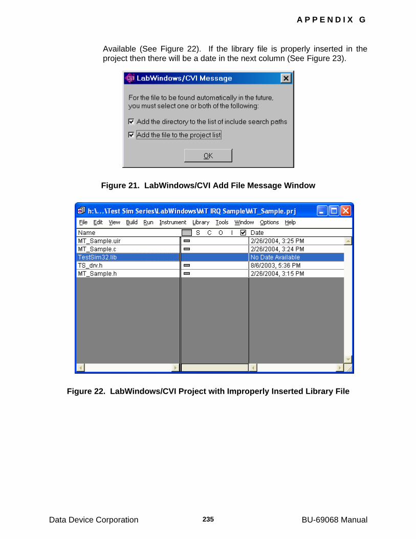
A P P E N D I X G
Data Device Corporation BU-69068 Manual 235
Available (See Figure 22). If the library file is properly inserted in the project then there will be a date in the next column (See Figure 23).
Figure 21. LabWindows/CVI Add File Message Window
Figure 22. LabWindows/CVI Project with Improperly Inserted Library File
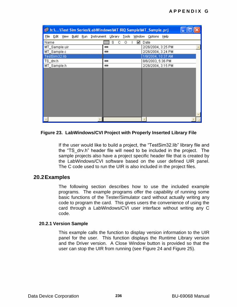
A P P E N D I X G
Data Device Corporation BU-69068 Manual 236
Figure 23. LabWindows/CVI Project with Properly Inserted Library File
If the user would like to build a project, the ―TestSim32.lib‖ library file and the ―TS_drv.h‖ header file will need to be included in the project. The sample projects also have a project specific header file that is created by the LabWindows/CVI software based on the user defined UIR panel. The C code used to run the UIR is also included in the project files.
20.2 Examples
The following section describes how to use the included example programs. The example programs offer the capability of running some basic functions of the Tester/Simulator card without actually writing any code to program the card. This gives users the convenience of using the card through a LabWindows/CVI user interface without writing any C code.
20.2.1 Version Sample
This example calls the function to display version information to the UIR panel for the user. This function displays the Runtime Library version and the Driver version. A Close Window button is provided so that the user can stop the UIR from running (see Figure 24 and Figure 25).
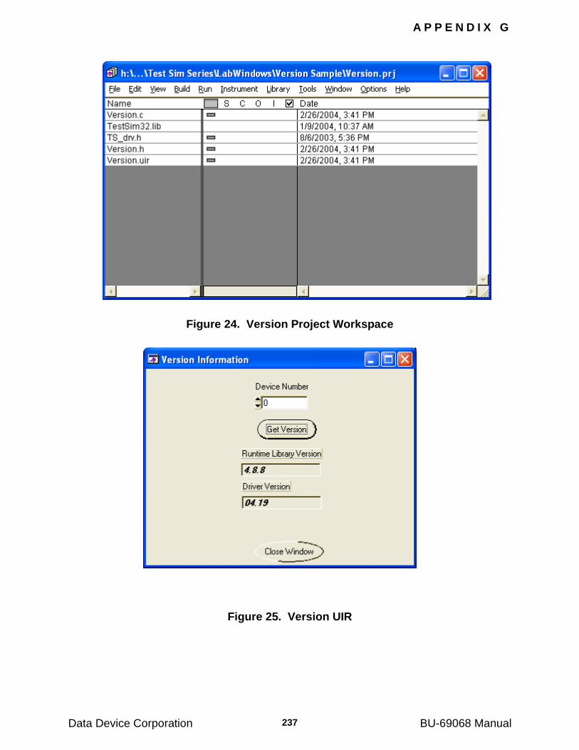
A P P E N D I X G
Data Device Corporation BU-69068 Manual 237
Figure 24. Version Project Workspace
Figure 25. Version UIR
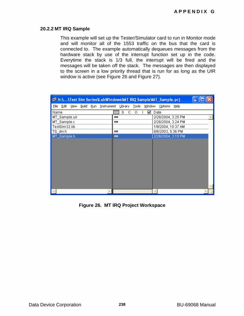
A P P E N D I X G
Data Device Corporation BU-69068 Manual 238
20.2.2 MT IRQ Sample
This example will set up the Tester/Simulator card to run in Monitor mode and will monitor all of the 1553 traffic on the bus that the card is connected to. The example automatically dequeues messages from the hardware stack by use of the interrupt function set up in the code. Everytime the stack is 1/3 full, the interrupt will be fired and the messages will be taken off the stack. The messages are then displayed to the screen in a low priority thread that is run for as long as the UIR window is active (see Figure 26 and Figure 27).
Figure 26. MT IRQ Project Workspace
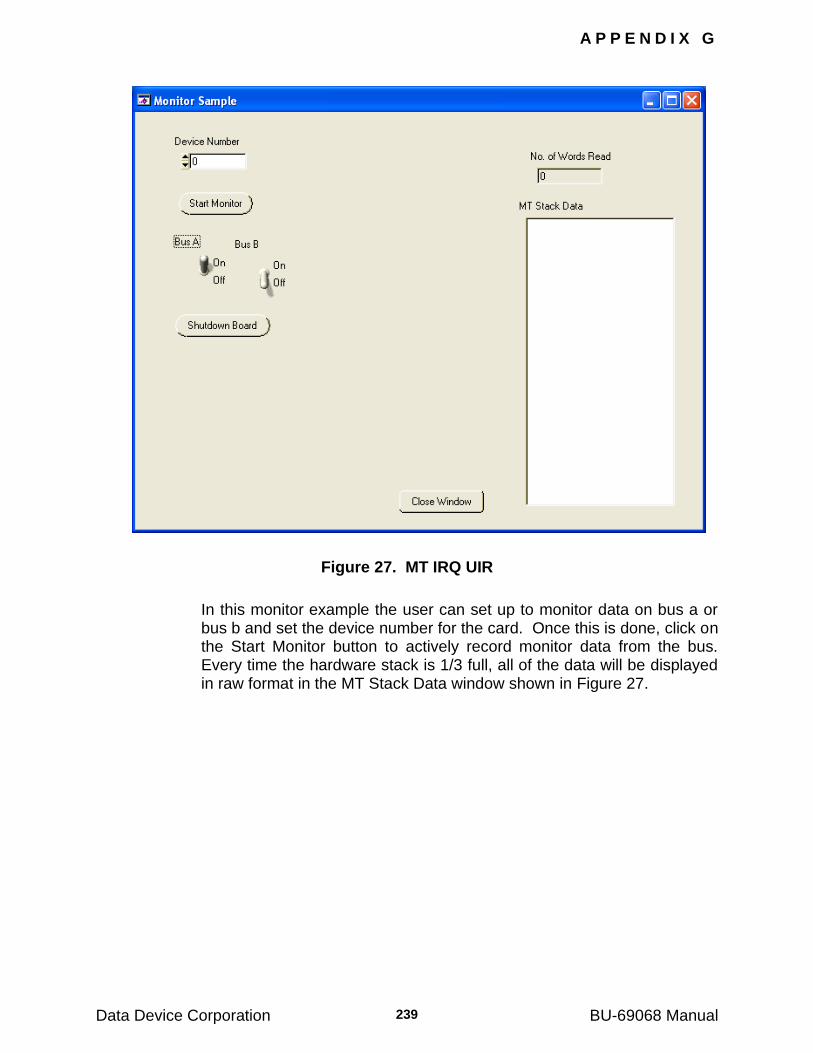
A P P E N D I X G
Data Device Corporation BU-69068 Manual 239
Figure 27. MT IRQ UIR
In this monitor example the user can set up to monitor data on bus a or bus b and set the device number for the card. Once this is done, click on the Start Monitor button to actively record monitor data from the bus. Every time the hardware stack is 1/3 full, all of the data will be displayed in raw format in the MT Stack Data window shown in Figure 27.
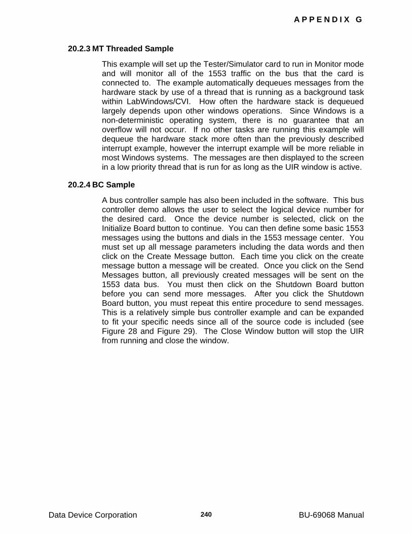
A P P E N D I X G
Data Device Corporation BU-69068 Manual 240
20.2.3 MT Threaded Sample
This example will set up the Tester/Simulator card to run in Monitor mode and will monitor all of the 1553 traffic on the bus that the card is connected to. The example automatically dequeues messages from the hardware stack by use of a thread that is running as a background task within LabWindows/CVI. How often the hardware stack is dequeued largely depends upon other windows operations. Since Windows is a non-deterministic operating system, there is no guarantee that an overflow will not occur. If no other tasks are running this example will dequeue the hardware stack more often than the previously described interrupt example, however the interrupt example will be more reliable in most Windows systems. The messages are then displayed to the screen in a low priority thread that is run for as long as the UIR window is active.
20.2.4 BC Sample
A bus controller sample has also been included in the software. This bus controller demo allows the user to select the logical device number for the desired card. Once the device number is selected, click on the Initialize Board button to continue. You can then define some basic 1553 messages using the buttons and dials in the 1553 message center. You must set up all message parameters including the data words and then click on the Create Message button. Each time you click on the create message button a message will be created. Once you click on the Send Messages button, all previously created messages will be sent on the 1553 data bus. You must then click on the Shutdown Board button before you can send more messages. After you click the Shutdown Board button, you must repeat this entire procedure to send messages. This is a relatively simple bus controller example and can be expanded to fit your specific needs since all of the source code is included (see Figure 28 and Figure 29). The Close Window button will stop the UIR from running and close the window.
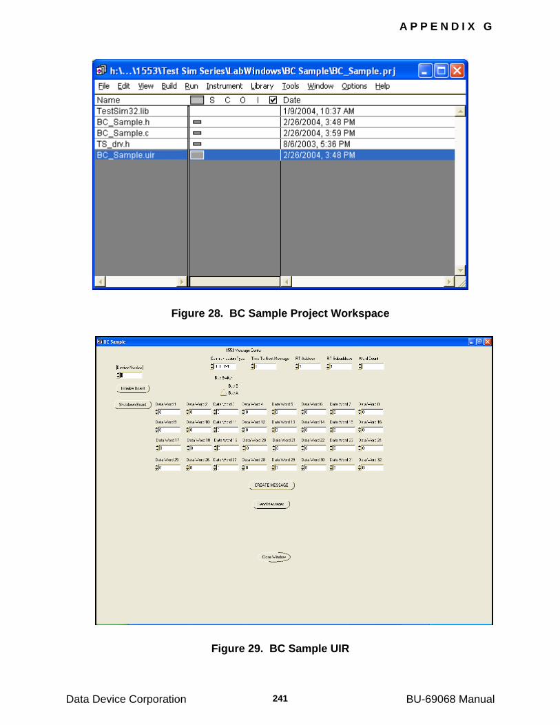
A P P E N D I X G
Data Device Corporation BU-69068 Manual 241
Figure 28. BC Sample Project Workspace
Figure 29. BC Sample UIR
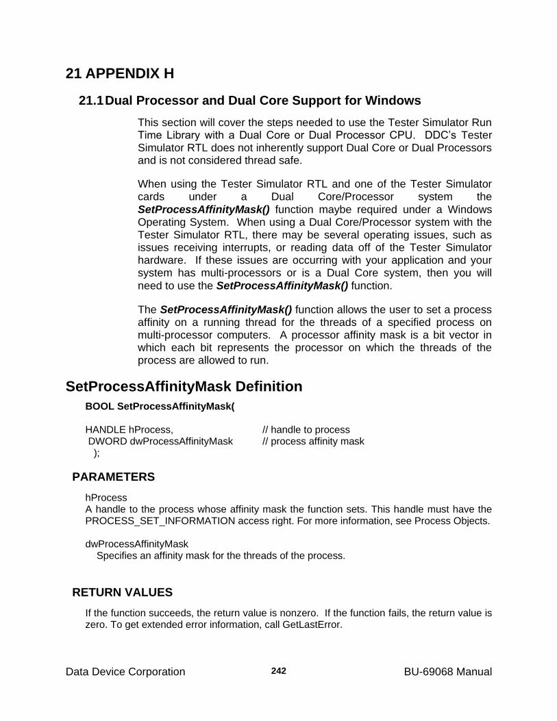
Data Device Corporation BU-69068 Manual
242
21 APPENDIX H
21.1 Dual Processor and Dual Core Support for Windows
This section will cover the steps needed to use the Tester Simulator Run Time Library with a Dual Core or Dual Processor CPU. DDC‘s Tester Simulator RTL does not inherently support Dual Core or Dual Processors and is not considered thread safe.
When using the Tester Simulator RTL and one of the Tester Simulator cards under a Dual Core/Processor system the
SetProcessAffinityMask() function maybe required under a Windows Operating System. When using a Dual Core/Processor system with the Tester Simulator RTL, there may be several operating issues, such as issues receiving interrupts, or reading data off of the Tester Simulator hardware. If these issues are occurring with your application and your system has multi-processors or is a Dual Core system, then you will
need to use the SetProcessAffinityMask() function.
The SetProcessAffinityMask() function allows the user to set a process affinity on a running thread for the threads of a specified process on multi-processor computers. A processor affinity mask is a bit vector in which each bit represents the processor on which the threads of the process are allowed to run.
SetProcessAffinityMask Definition
BOOL SetProcessAffinityMask(
HANDLE hProcess, // handle to process DWORD dwProcessAffinityMask // process affinity mask );
PARAMETERS
hProcess A handle to the process whose affinity mask the function sets. This handle must have the PROCESS_SET_INFORMATION access right. For more information, see Process Objects. dwProcessAffinityMask Specifies an affinity mask for the threads of the process.
RETURN VALUES
If the function succeeds, the return value is nonzero. If the function fails, the return value is zero. To get extended error information, call GetLastError.
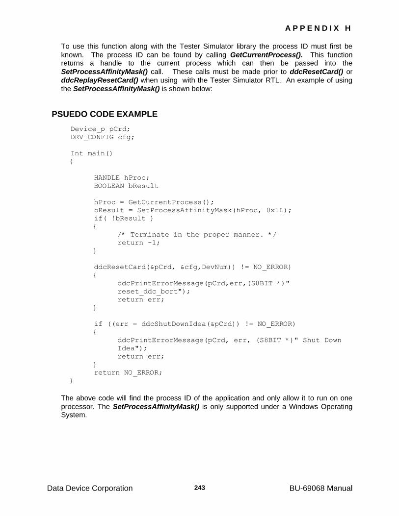
A P P E N D I X H
Data Device Corporation BU-69068 Manual 243
To use this function along with the Tester Simulator library the process ID must first be
known. The process ID can be found by calling GetCurrentProcess(). This function returns a handle to the current process which can then be passed into the
SetProcessAffinityMask() call. These calls must be made prior to ddcResetCard() or
ddcReplayResetCard() when using with the Tester Simulator RTL. An example of using
the SetProcessAffinityMask() is shown below:
PSUEDO CODE EXAMPLE
Device_p pCrd;
DRV_CONFIG cfg;
Int main()
{
HANDLE hProc;
BOOLEAN bResult
hProc = GetCurrentProcess();
bResult = SetProcessAffinityMask(hProc, 0x1L);
if( !bResult )
{
/* Terminate in the proper manner. */
return -1;
}
ddcResetCard(&pCrd, &cfg,DevNum)) != NO_ERROR)
{
ddcPrintErrorMessage(pCrd,err,(S8BIT *)"
reset_ddc_bcrt");
return err;
}
if ((err = ddcShutDownIdea(&pCrd)) != NO_ERROR)
{
ddcPrintErrorMessage(pCrd, err, (S8BIT *)" Shut Down
Idea");
return err;
}
return NO_ERROR;
}
The above code will find the process ID of the application and only allow it to run on one
processor. The SetProcessAffinityMask() is only supported under a Windows Operating System.
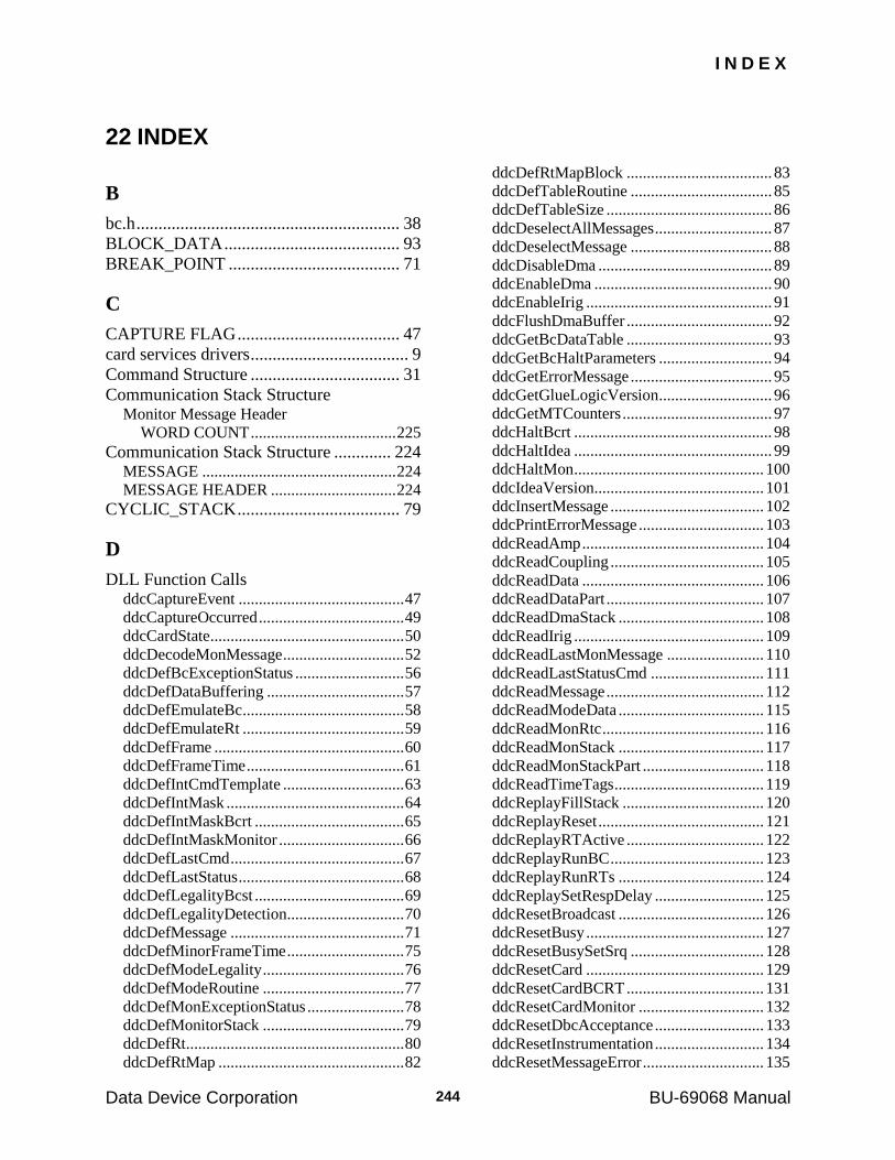
I N D E X
Data Device Corporation BU-69068 Manual 244
22 INDEX
B
bc.h ............................................................ 38
BLOCK_DATA ........................................ 93
BREAK_POINT ....................................... 71
C
CAPTURE FLAG ..................................... 47
card services drivers .................................... 9
Command Structure .................................. 31
Communication Stack Structure Monitor Message Header
WORD COUNT .................................... 225
Communication Stack Structure ............. 224 MESSAGE ................................................ 224
MESSAGE HEADER ............................... 224
CYCLIC_STACK ..................................... 79
D
DLL Function Calls ddcCaptureEvent ......................................... 47
ddcCaptureOccurred .................................... 49
ddcCardState ................................................ 50
ddcDecodeMonMessage .............................. 52
ddcDefBcExceptionStatus ........................... 56
ddcDefDataBuffering .................................. 57
ddcDefEmulateBc ........................................ 58
ddcDefEmulateRt ........................................ 59
ddcDefFrame ............................................... 60
ddcDefFrameTime ....................................... 61
ddcDefIntCmdTemplate .............................. 63
ddcDefIntMask ............................................ 64
ddcDefIntMaskBcrt ..................................... 65
ddcDefIntMaskMonitor ............................... 66
ddcDefLastCmd ........................................... 67
ddcDefLastStatus ......................................... 68
ddcDefLegalityBcst ..................................... 69
ddcDefLegalityDetection ............................. 70
ddcDefMessage ........................................... 71
ddcDefMinorFrameTime ............................. 75
ddcDefModeLegality ................................... 76
ddcDefModeRoutine ................................... 77
ddcDefMonExceptionStatus ........................ 78
ddcDefMonitorStack ................................... 79
ddcDefRt ...................................................... 80
ddcDefRtMap .............................................. 82
ddcDefRtMapBlock .................................... 83
ddcDefTableRoutine ................................... 85
ddcDefTableSize ......................................... 86
ddcDeselectAllMessages ............................. 87
ddcDeselectMessage ................................... 88
ddcDisableDma ........................................... 89
ddcEnableDma ............................................ 90
ddcEnableIrig .............................................. 91
ddcFlushDmaBuffer .................................... 92
ddcGetBcDataTable .................................... 93
ddcGetBcHaltParameters ............................ 94
ddcGetErrorMessage ................................... 95
ddcGetGlueLogicVersion ............................ 96
ddcGetMTCounters ..................................... 97
ddcHaltBcrt ................................................. 98
ddcHaltIdea ................................................. 99
ddcHaltMon ............................................... 100
ddcIdeaVersion .......................................... 101
ddcInsertMessage ...................................... 102
ddcPrintErrorMessage ............................... 103
ddcReadAmp ............................................. 104
ddcReadCoupling ...................................... 105
ddcReadData ............................................. 106
ddcReadDataPart ....................................... 107
ddcReadDmaStack .................................... 108
ddcReadIrig ............................................... 109
ddcReadLastMonMessage ........................ 110
ddcReadLastStatusCmd ............................ 111
ddcReadMessage ....................................... 112
ddcReadModeData .................................... 115
ddcReadMonRtc ........................................ 116
ddcReadMonStack .................................... 117
ddcReadMonStackPart .............................. 118
ddcReadTimeTags ..................................... 119
ddcReplayFillStack ................................... 120
ddcReplayReset ......................................... 121
ddcReplayRTActive .................................. 122
ddcReplayRunBC ...................................... 123
ddcReplayRunRTs .................................... 124
ddcReplaySetRespDelay ........................... 125
ddcResetBroadcast .................................... 126
ddcResetBusy ............................................ 127
ddcResetBusySetSrq ................................. 128
ddcResetCard ............................................ 129
ddcResetCardBCRT .................................. 131
ddcResetCardMonitor ............................... 132
ddcResetDbcAcceptance ........................... 133
ddcResetInstrumentation ........................... 134
ddcResetMessageError .............................. 135
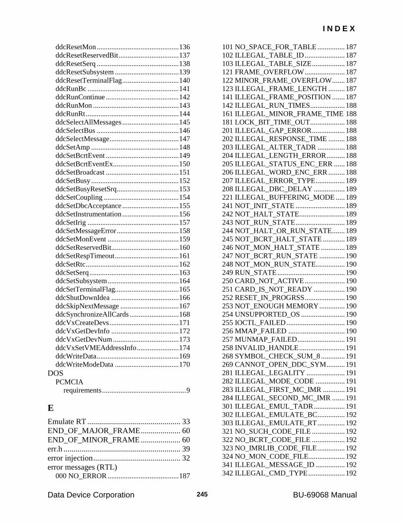
I N D E X
Data Device Corporation BU-69068 Manual 245
ddcResetMon ............................................. 136
ddcResetReservedBit ................................. 137
ddcResetSerq ............................................. 138
ddcResetSubsystem ................................... 139
ddcResetTerminalFlag ............................... 140
ddcRunBc .................................................. 141
ddcRunContinue ........................................ 142
ddcRunMon ............................................... 143
ddcRunRt ................................................... 144
ddcSelectAllMessages ............................... 145
ddcSelectBus ............................................. 146
ddcSelectMessage ...................................... 147
ddcSetAmp ................................................ 148
ddcSetBcrtEvent ........................................ 149
ddcSetBcrtEventEx .................................... 150
ddcSetBroadcast ........................................ 151
ddcSetBusy ................................................ 152
ddcSetBusyResetSrq .................................. 153
ddcSetCoupling ......................................... 154
ddcSetDbcAcceptance ............................... 155
ddcSetInstrumentation ............................... 156
ddcSetIrig .................................................. 157
ddcSetMessageError .................................. 158
ddcSetMonEvent ....................................... 159
ddcSetReservedBit..................................... 160
ddcSetRespTimeout ................................... 161
ddcSetRtc ................................................... 162
ddcSetSerq ................................................. 163
ddcSetSubsystem ....................................... 164
ddcSetTerminalFlag ................................... 165
ddcShutDownIdea ..................................... 166
ddcSkipNextMessage ................................ 167
ddcSynchronizeAllCards ........................... 168
ddcVxCreateDevs ...................................... 171
ddcVxGetDevInfo ..................................... 172
ddcVxGetDevNum .................................... 173
ddcVxSetVMEAddressInfo ....................... 174
ddcWriteData ............................................. 169
ddcWriteModeData ................................... 170
DOS PCMCIA
requirements .............................................. 9
E
Emulate RT ............................................... 33
END_OF_MAJOR_FRAME .................... 60
END_OF_MINOR_FRAME .................... 60
err.h ........................................................... 39
error injection ............................................ 32
error messages (RTL) 000 NO_ERROR ....................................... 187
101 NO_SPACE_FOR_TABLE ............... 187
102 ILLEGAL_TABLE_ID ...................... 187
103 ILLEGAL_TABLE_SIZE .................. 187
121 FRAME_OVERFLOW ...................... 187
122 MINOR_FRAME_OVERFLOW ....... 187
123 ILLEGAL_FRAME_LENGTH ......... 187
141 ILLEGAL_FRAME_POSITION ....... 187
142 ILLEGAL_RUN_TIMES ................... 188
161 ILLEGAL_MINOR_FRAME_TIME 188
181 LOCK_BIT_TIME_OUT ................... 188
201 ILLEGAL_GAP_ERROR .................. 188
202 ILLEGAL_RESPONSE_TIME ......... 188
203 ILLEGAL_ALTER_TADR ............... 188
204 ILLEGAL_LENGTH_ERROR .......... 188
205 ILLEGAL_STATUS_ENC_ERR ...... 188
206 ILLEGAL_WORD_ENC_ERR ......... 188
207 ILLEGAL_ERROR_TYPE ................ 189
208 ILLEGAL_DBC_DELAY ................. 189
221 ILLEGAL_BUFFERING_MODE ..... 189
241 NOT_INIT_STATE ........................... 189
242 NOT_HALT_STATE ......................... 189
243 NOT_RUN_STATE ........................... 189
244 NOT_HALT_OR_RUN_STATE ....... 189
245 NOT_BCRT_HALT_STATE ............ 189
246 NOT_MON_HALT_STATE ............. 189
247 NOT_BCRT_RUN_STATE .............. 190
248 NOT_MON_RUN_STATE................ 190
249 RUN_STATE ..................................... 190
250 CARD_NOT_ACTIVE ...................... 190
251 CARD_IS_NOT_READY ................. 190
252 RESET_IN_PROGRSS ...................... 190
253 NOT_ENOUGH MEMORY .............. 190
254 UNSUPPORTED_OS ........................ 190
255 IOCTL_FAILED ................................ 190
256 MMAP_FAILED ............................... 190
257 MUNMAP_FAILED .......................... 191
258 INVALID_HANDLE ......................... 191
268 SYMBOL_CHECK_SUM_8 ............. 191
269 CANNOT_OPEN_DDC_SYM .......... 191
281 ILLEGAL_LEGALITY ..................... 191
282 ILLEGAL_MODE_CODE ................ 191
283 ILLEGAL_FIRST_MC_IMR ............ 191
284 ILLEGAL_SECOND_MC_IMR ....... 191
301 ILLEGAL_EMUL_TADR ................. 191
302 ILLEGAL_EMULATE_BC ............... 192
303 ILLEGAL_EMULATE_RT ............... 192
321 NO_SUCH_CODE_FILE .................. 192
322 NO_BCRT_CODE_FILE .................. 192
323 NO_IMRLIB_CODE_FILE ............... 192
324 NO_MON_CODE_FILE.................... 192
341 ILLEGAL_MESSAGE_ID ................ 192
342 ILLEGAL_CMD_TYPE .................... 192
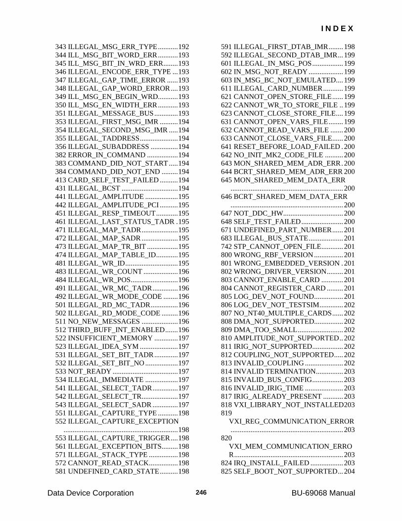
I N D E X
Data Device Corporation BU-69068 Manual 246
343 ILLEGAL_MSG_ERR_TYPE ........... 192
344 ILL_MSG_BIT_WORD_ERR ........... 193
345 ILL_MSG_BIT_IN_WRD_ERR ........ 193
346 ILLEGAL_ENCODE_ERR_TYPE ... 193
347 ILLEGAL_GAP_TIME_ERROR ...... 193
348 ILLEGAL_GAP_WORD_ERROR .... 193
349 ILL_MSG_EN_BEGIN_WRD........... 193
350 ILL_MSG_EN_WIDTH_ERR ........... 193
351 ILLEGAL_MESSAGE_BUS ............. 193
353 ILLEGAL_FIRST_MSG_IMR .......... 194
354 ILLEGAL_SECOND_MSG_IMR ..... 194
355 ILLEGAL_TADDRESS ..................... 194
356 ILLEGAL_SUBADDRESS ............... 194
382 ERROR_IN_COMMAND ................. 194
383 COMMAND_DID_NOT_START ..... 194
384 COMMAND_DID_NOT_END ......... 194
413 CARD_SELF_TEST_FAILED .......... 194
431 ILLEGAL_BCST ............................... 194
441 ILLEGAL_AMPLITUDE .................. 195
442 ILLEGAL_AMPLITUDE_PCI .......... 195
451 ILLEGAL_RESP_TIMEOUT ............ 195
461 ILLEGAL_LAST_STATUS_TADR . 195
471 ILLEGAL_MAP_TADR .................... 195
472 ILLEGAL_MAP_SADR .................... 195
473 ILLEGAL_MAP_TR_BIT ................. 195
474 ILLEGAL_MAP_TABLE_ID ............ 195
481 ILLEGAL_WR_ID ............................. 195
483 ILLEGAL_WR_COUNT ................... 196
484 ILLEGAL_WR_POS .......................... 196
491 ILLEGAL_WR_MC_TADR .............. 196
492 ILLEGAL_WR_MODE_CODE ........ 196
501 ILLEGAL_RD_MC_TADR ............... 196
502 ILLEGAL_RD_MODE_CODE ......... 196
511 NO_NEW_MESSAGES .................... 196
512 THIRD_BUFF_INT_ENABLED ....... 196
522 INSUFFICIENT_MEMORY ............. 197
523 ILLEGAL_IDEA_SYM ..................... 197
531 ILLEGAL_SET_BIT_TADR ............. 197
532 ILLEGAL_SET_BIT_NO .................. 197
533 NOT_READY .................................... 197
534 ILLEGAL_IMMEDIATE .................. 197
541 ILLEGAL_SELECT_TADR .............. 197
542 ILLEGAL_SELECT_TR .................... 197
543 ILLEGAL_SELECT_SADR .............. 197
551 ILLEGAL_CAPTURE_TYPE ........... 198
552 ILLEGAL_CAPTURE_EXCEPTION
............................................................... 198
553 ILLEGAL_CAPTURE_TRIGGER .... 198
561 ILLEGAL_EXCEPTION_BITS......... 198
571 ILLEGAL_STACK_TYPE ................ 198
572 CANNOT_READ_STACK ................ 198
581 UNDEFINED_CARD_STATE .......... 198
591 ILLEGAL_FIRST_DTAB_IMR ........ 198
592 ILLEGAL_SECOND_DTAB_IMR ... 199
601 ILLEGAL_IN_MSG_POS ................. 199
602 IN_MSG_NOT_READY ................... 199
603 IN_MSG_BC_NOT_EMULATED .... 199
611 ILLEGAL_CARD_NUMBER ........... 199
621 CANNOT_OPEN_STORE_FILE ...... 199
622 CANNOT_WR_TO_STORE_FILE .. 199
623 CANNOT_CLOSE_STORE_FILE .... 199
631 CANNOT_OPEN_VARS_FILE ........ 199
632 CANNOT_READ_VARS_FILE ....... 200
633 CANNOT_CLOSE_VARS_FILE...... 200
641 RESET_BEFORE_LOAD_FAILED . 200
642 NO_INIT_MK2_CODE_FILE .......... 200
643 MON_SHARED_MEM_ADR_ERR . 200
644 BCRT_SHARED_MEM_ADR_ERR 200
645 MON_SHARED_MEM_DATA_ERR
.............................................................. 200
646 BCRT_SHARED_MEM_DATA_ERR
.............................................................. 200
647 NOT_DDC_HW ................................. 200
648 SELF_TEST_FAILED ....................... 200
671 UNDEFINED_PART_NUMBER ...... 201
683 ILLEGAL_BUS_STATE ................... 201
742 STP_CANNOT_OPEN_FILE............ 201
800 WRONG_RBF_VERSION ................ 201
801 WRONG_EMBEDDED_VERSION . 201
802 WRONG_DRIVER_VERSION ......... 201
803 CANNOT_ENABLE_CARD ............ 201
804 CANNOT_REGISTER_CARD ......... 201
805 LOG_DEV_NOT_FOUND................ 201
806 LOG_DEV_NOT_TESTSIM ............. 202
807 NO_NT40_MULTIPLE_CARDS ...... 202
808 DMA_NOT_SUPPORTED................ 202
809 DMA_TOO_SMALL ......................... 202
810 AMPLITUDE_NOT_SUPPORTED .. 202
811 IRIG_NOT_SUPPORTED ................. 202
812 COUPLING_NOT_SUPPORTED ..... 202
813 INVALID_COUPLING ..................... 202
814 INVALID TERMINATION............... 203
815 INVALID_BUS_CONFIG ................. 203
816 INVALID_IRIG_TIME ..................... 203
817 IRIG_ALREADY_PRESENT ........... 203
818 VXI_LIBRARY_NOT_INSTALLED 203
819
VXI_REG_COMMUNICATION_ERROR
.............................................................. 203
820
VXI_MEM_COMMUNICATION_ERRO
R ............................................................ 203
824 IRQ_INSTALL_FAILED .................. 203
825 SELF_BOOT_NOT_SUPPORTED ... 204
I N D E X
Data Device Corporation BU-69068 Manual 247
826 MON_STACK_OVERFLOW ............ 204
828 CARD_NOT_READY_WRITE_RTC
............................................................... 204
829 CARD_NOT_READY_IRIG ............. 204
830 VXI_A16_ONLY ............................... 204
831
CARD_NOT_READY_SYNCHRONIZE
............................................................... 204
832
CARD_NOT_READY_DEF_BC_EXCEP
TION_STATUS .................................... 204
833
CARD_NOT_READY_DEF_EMULATE_
BC ......................................................... 204
834
CARD_NOT_READY_DEF_MINOR_FR
AME_TIME .......................................... 205
835 CARD_NOT_READY_RUN_BC ..... 205
836
CARD_NOT_READY_RUN_CONTINU
E ............................................................ 205
837
CARD_NOT_READY_SKIP_NEXT_ME
SSAGE .................................................. 205
838 CARD_NOT_READY_INIT ............. 205
839
CARD_NOT_READY_SET_RESP_TIME
OUT ....................................................... 205
840
CARD_NOT_READY_CAPTURE_EVE
NT ......................................................... 205
841
CARD_NOT_READY_DEF_MON_EXC
EPTION ................................................. 205
842
CARD_NOT_READY_DEF_MON_STA
CK ......................................................... 205
843 CARD_NOT_READY_RUN_MON . 206
844 CARD_NOT_READY_SELECT_BUS
............................................................... 206
845
CARD_NOT_READY_REPLAY_RUN_B
C ............................................................ 206
846
CARD_NOT_READY_REPLAY_RUN_R
TS .......................................................... 206
847 CARD_NOT_READY_RUN_RT ...... 206
848
CARD_NOT_READY_DEF_LEG_BCST
............................................................... 206
849 CARD_NOT_READY_DEF_LEG_DET
............................................................... 206
850
CARD_NOT_READY_DEF_INT_CMD_
TEMPL ................................................. 206
851 LOG_DEV_IN_USE .......................... 206
900 ILLEGAL_DAT_POS_MAG ............ 207
901 ILLEGAL_DAT_POS ....................... 207
902 WARNING_COUNT_READ ............ 207
950 CONFIG_FILE_NOT_FOUND ......... 207
951 DEVICE_MAPPING_ERROR .......... 207
952 HW_NOT_DOS_ENABLED ............ 207
953 HW_DEVICE_NOT_FOUND ........... 207
954 UNSUPPORTED_CARD_TYPE ...... 207
Error_t Return Value ............................................... 31
EXCEPTION ............................................ 54
F
Frame ........................................................ 60
Frame Array .............................................. 32
H
headquarters ................................................ 1
I
IMR ........................................................... 83
Installation Software Menu .............................................. 4
Software RTL ................................................ 4
int.h ........................................................... 40
Intermessage Routines ............................ 212 BLOCK_ DATA_BC ................................ 222
BLOCK_ DATA_RT ................................ 223
INTERRUPT AFTER ACCESSING TX/RX
DATA TABLE...................................... 216
INTERRUPT AFTER MODE COMMAND
TEMPLATE MATCH .......................... 217
INTERRUPT AFTER MODE COMMANDS
.............................................................. 216
INTERRUPT AFTER TX/RX COMMAND
TEMPLATE MATCH .......................... 217
INTERRUPT ON END OF MESSAGE ... 215
INTERRUPT ON FRAME SYMBOL ...... 215
NO OPERATION ..................................... 214
NO RESPONSE ON BOTH BUSES ........ 219
RESET DISCRETE 0 ................................ 221
RESET DISCRETE 1 ................................ 221
RESET DISCRETE 2 ................................ 222
RESET DISCRETE 3 ................................ 222
RESET OUTPUT TRIGGER .................... 219
RESET STATUS BIT IN STATUS .......... 218
I N D E X
Data Device Corporation BU-69068 Manual 248
RESET THE BUSY BIT IN STATUS ...... 220
RESET THE SERVICE REQUEST BIT IN
STATUS ................................................ 216
RETRY CURRENT MESSAGE ON
ALTERNATE BUS............................... 214
RETRY CURRENT MESSAGEAND
REMAIN ON ALTERNATE BUS ....... 214
RETRY ON SAME BUS .......................... 215
RETRY ON SAME BUS AND THEN ON
ALTERNATE BUS............................... 218
SET BUSY BIT AND RESET SRQ BIT .. 220
SET DISCRETE 0 ..................................... 220
SET DISCRETE 1 ..................................... 221
SET DISCRETE 2 ..................................... 221
SET DISCRETE 3 ..................................... 221
SET OUTPUT TRIGGER ......................... 218
SET SRQ BIT AND RESET BUSY BIT IN
STATUS ................................................ 220
SET STATUS BIT IN STATUS ............... 218
SET THE BUSY BIT IN STATUS ........... 219
SET THE SERVICE REQUEST BIT IN
STATUS ................................................ 216
SKIP NEXT MESSAGE ........................... 220
SKIP NEXT MESSAGE ONCE ............... 222
SKIP NEXT MESSAGE ONCE EX ......... 223
TIME-TAG ................................................ 217
WAIT FOR INPUT TRIGGER ................. 219
INTERRUPT MASK ................................ 29
interrupts ................................................. 208 generating .................................................... 26
MT ............................................................... 26
Interrupts INTERRUPT MASK ................................. 211
irq.h ........................................................... 41
L
LAST COMMAND ................................ 111
LAST STATUS ...................................... 111
legality....................................................... 76
M
Message Structure ..................................... 32
Minor Frame Time .................................... 33
Monitor Message Header BUS ........................................................... 224
CAP ........................................................... 224
CMODE ..................................................... 225
ERROR CODE .......................................... 225
FLS FLG .................................................... 226
ILL ............................................................. 224
INVALID COMMAND ............................ 225
IRIG FLG .................................................. 225
LW ............................................................. 225
MODE COMMAND ................................. 225
P 226
RECEIVE .................................................. 225
RECEIVE STATUS .................................. 225
RTC HIGH ................................................ 225
RTC LOW ................................................. 225
SW ............................................................. 226
SYSTEM DATE ....................................... 225
TRANSMIT .............................................. 225
TRANSMIT STATUS .............................. 225
V .............................................................. 226
mt.h ........................................................... 42
N
Next Message Pointer ............................. 117
NON_CYCLIC_STACK .......................... 79
P
PCMCIA standard ......................................................... 9
R
rep.h .......................................................... 43
response timeout ..................................... 161
rt.h ............................................................. 44
RTC ......................................................... 116
S
Sample Application ................................... 30
SKIP .......................................................... 71
socket services .......................................... 10
Software Menu Installation ........................................... 4
RTL Installation ............................................ 4
Structures CARD_STATE ......................................... 229
COM_ST ................................................... 229
ERR_ST .................................................... 229
MON_MST ............................................... 230
RT_DEFS .................................................. 230
RT_DEFS_NEW ....................................... 230
I N D E X
Data Device Corporation BU-69068 Manual 249
T
technical support ......................................... 1
TESTSIM.CFG ......................................... 12
TS_DRV.H................................................ 30
V
VxWorks programming ............................ 25
vxworks.h .................................................. 45