Embed Size (px)
Citation preview
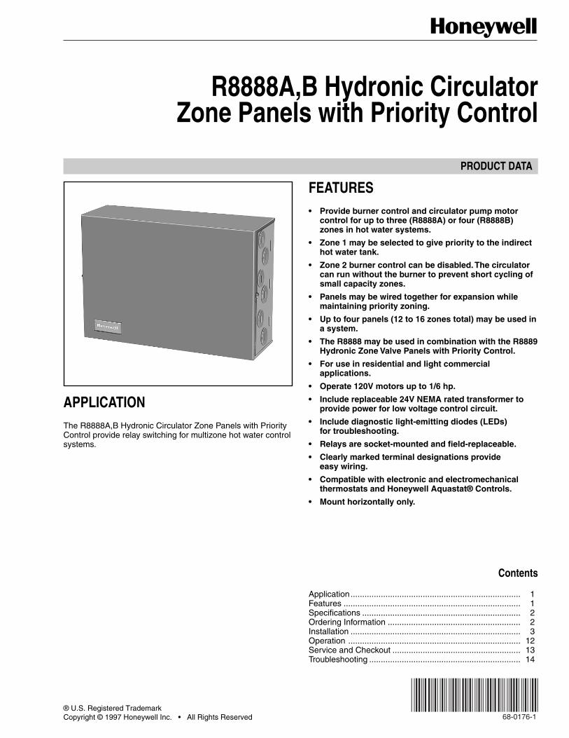
PRODUCT DATA
® U.S. Registered TrademarkCopyright © 1997 Honeywell Inc. • All Rights Reserved X-XX UL
R8888A,B Hydronic CirculatorZone Panels with Priority Control
APPLICATIONThe R8888A,B Hydronic Circulator Zone Panels with PriorityControl provide relay switching for multizone hot water controlsystems.
FEATURES• Provide burner control and circulator pump motor
control for up to three (R8888A) or four (R8888B)zones in hot water systems.
• Zone 1 may be selected to give priority to the indirecthot water tank.
• Zone 2 burner control can be disabled. The circulatorcan run without the burner to prevent short cycling ofsmall capacity zones.
• Panels may be wired together for expansion whilemaintaining priority zoning.
• Up to four panels (12 to 16 zones total) may be used ina system.
• The R8888 may be used in combination with the R8889Hydronic Zone Valve Panels with Priority Control.
• For use in residential and light commercialapplications.
• Operate 120V motors up to 1/6 hp.
• Include replaceable 24V NEMA rated transformer toprovide power for low voltage control circuit.
• Include diagnostic light-emitting diodes (LEDs)for troubleshooting.
• Relays are socket-mounted and field-replaceable.
• Clearly marked terminal designations provideeasy wiring.
• Compatible with electronic and electromechanicalthermostats and Honeywell Aquastat® Controls.
• Mount horizontally only.
Contents
Application......................................................................... 1Features ............................................................................ 1Specifications .................................................................... 2Ordering Information ......................................................... 2Installation ......................................................................... 3Operation .......................................................................... 12Service and Checkout ....................................................... 13Troubleshooting ................................................................. 14
68-0176-1
R8888A,B HYDRONIC CIRCULATOR ZONE PANELS WITH PRIORITY CONTROL
68-0176—1 2
ORDERING INFORMATIONFor ordering information when purchasing replacement and modernization products from your TRADELINE® wholesaler or yourdistributor, refer to the TRADELINE catalog or price sheets for complete ordering number or specify—
1. Order number.2. Number of zones.
If you have additional questions, need further information, or would like to comment on our products or services, please write orphone:1. Your local Home and Building Control Sales Office (check white pages of your phone directory).2. Home and Building Control Customer Relations
Honeywell, 1885 Douglas Drive NorthMinneapolis, Minnesota 55422-4386
In Canada—Honeywell Limited/Honeywell Limitée, 35 Dynamic Drive, Scarborough, Ontario M1V 4Z9.International Sales and Service Offices in all principal cities of the world. Manufacturing in Australia, Canada, Finland, France,Germany, Japan, Mexico, Netherlands, Spain, Taiwan, United Kingdom, U.S.A.
SPECIFICATIONSIMPORTANT
The specifications given in this publication do notinclude normal manufacturing tolerances. This unitmay not exactly match the listed specifications. Also,this product is tested and calibrated under closelycontrolled conditions, and some minor differences inperformance can be expected if those conditions arechanged.
TRADELINE® ModelsTRADELINE models are selected and packaged to provideease of stocking, ease of handling, and maximumreplacement value.
TRADELINE® Models Available:R8888A Hydronic Circulator Zone Panel with Priority
Control—Provides switching for hot water controlsystems (up to three zones) with the ability to field-configure Zone 1 as priority over the others; includesseparate 24V NEMA rated transformer that providespower to low voltage circuit.
R8888B Hydronic Circulator Zone Panel with PriorityControl—Provides switching for hot water controlsystems (up to four zones) with the ability to field-configure Zone 1 as priority over the others; includesseparate 24V NEMA rated transformer that providespower to low voltage circuit.
Electrical Ratings:Motor Load Ratings for Each Zone at 120 Vac:
Full Load: 4.4A.Locked Rotor : 26.4A.Horsepower: 1/6 hp.
Secondary Circuit: 20 VA max.
Thermostat Heat Anticipator Setting:0.12A.
Maximum Ambient Temperature Rating:40° F to 105° F (4° C to 41° C).
Humidity:0 To 90% rh, non-condensing.
Terminals:Captivated wire-clamp screw terminals.
Finish:Painted gray enamel.
Knockouts:Knockouts for 1/2 in. conduits in sides of case.
Dimensions:See Fig. 1.
Replaces:Up to four R845 Relays.
Approvals:Underwriters Laboratories Inc. listed: File no. E4436.Canadian Underwriters Laboratories.
Replacement Parts:AT20A1123 Transformer—24 Vac.208621 Replacement Relay.
R8888A,B HYDRONIC CIRCULATOR ZONE PANELS WITH PRIORITY CONTROL
68-0176—13
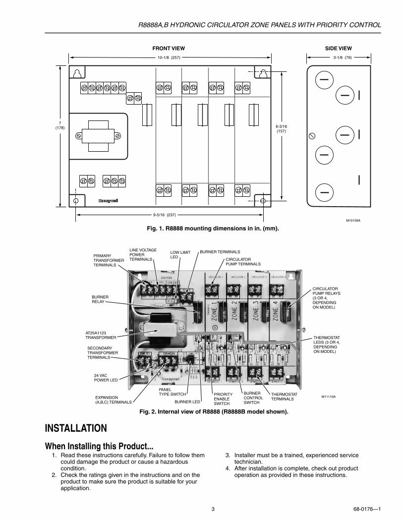
Fig. 1. R8888 mounting dimensions in in. (mm).
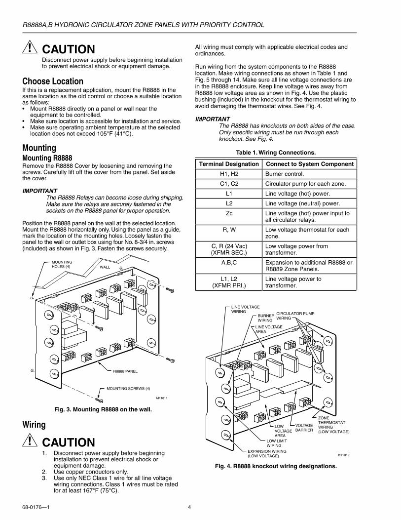
Fig. 2. Internal view of R8888 (R8888B model shown).
INSTALLATION
When Installing this Product...1. Read these instructions carefully. Failure to follow them
could damage the product or cause a hazardouscondition.
2. Check the ratings given in the instructions and on theproduct to make sure the product is suitable for yourapplication.
3. Installer must be a trained, experienced servicetechnician.
4. After installation is complete, check out productoperation as provided in these instructions.
FRONT VIEW SIDE VIEW
10-1/8 (257)
7(178) 6-3/16
(157)
9-5/16 (237)
3-1/8 (79)
M10159A
PRIMARYTRANSFORMERTERMINALS
LINE VOLTAGEPOWER TERMINALS
LOW LIMIT LED
BURNER TERMINALS
CIRCULATORPUMP TERMINALS
CIRCULATORPUMP RELAYS(3 OR 4, DEPENDINGON MODEL)
THERMOSTATLEDS (3 OR 4,DEPENDINGON MODEL)
BURNERCONTROLSWITCH
THERMOSTAT TERMINALS
PRIORITY ENABLE SWITCHBURNER LED
EXPANSION (A,B,C) TERMINALS
24 VAC POWER LED
SECONDARYTRANSFORMERTERMINALS
AT20A1123TRANSFORMER
BURNERRELAY
M11119A
PANELTYPE SWITCH
R8888A,B HYDRONIC CIRCULATOR ZONE PANELS WITH PRIORITY CONTROL
68-0176—1 4
All wiring must comply with applicable electrical codes andordinances.
Run wiring from the system components to the R8888location. Make wiring connections as shown in Table 1 andFig. 5 through 14. Make sure all line voltage connections arein the R8888 enclosure. Keep line voltage wires away fromR8888 low voltage area as shown in Fig. 4. Use the plasticbushing (included) in the knockout for the thermostat wiring toavoid damaging the thermostat wires. See Fig. 4.
IMPORTANTThe R8888 has knockouts on both sides of the case.Only specific wiring must be run through eachknockout. See Fig. 4.
Table 1. Wiring Connections.
CAUTIONDisconnect power supply before beginning installationto prevent electrical shock or equipment damage.
Choose LocationIf this is a replacement application, mount the R8888 in thesame location as the old control or choose a suitable locationas follows:• Mount R8888 directly on a panel or wall near the
equipment to be controlled.• Make sure location is accessible for installation and service.• Make sure operating ambient temperature at the selected
location does not exceed 105°F (41°C).
MountingMounting R8888Remove the R8888 Cover by loosening and removing thescrews. Carefully lift off the cover from the panel. Set asidethe cover.
IMPORTANTThe R8888 Relays can become loose during shipping.Make sure the relays are securely fastened in thesockets on the R8888 panel for proper operation.
Position the R8888 panel on the wall at the selected location.Mount the R8888 horizontally only. Using the panel as a guide,mark the location of the mounting holes. Loosely fasten thepanel to the wall or outlet box using four No. 8-3/4 in. screws(included) as shown in Fig. 3. Fasten the screws securely.
MOUNTING SCREWS (4)
MOUNTINGHOLES (4) WALL
R8888 PANEL
M11011
Fig. 3. Mounting R8888 on the wall.
Wiring
CAUTION1. Disconnect power supply before beginning
installation to prevent electrical shock orequipment damage.
2. Use copper conductors only.3. Use only NEC Class 1 wire for all line voltage
wiring connections. Class 1 wires must be ratedfor at least 167°F (75°C).
Fig. 4. R8888 knockout wiring designations.
LOW LIMITWIRING
LINE VOLTAGEWIRING
EXPANSION WIRING(LOW VOLTAGE)
CIRCULATOR PUMPWIRING
M11012
BURNERWIRING
ZONETHERMOSTATWIRING(LOW VOLTAGE)
LINE VOLTAGEAREA
LOW VOLTAGEAREA
VOLTAGEBARRIER
Terminal Designation Connect to System Component
H1, H2 Burner control.
C1, C2 Circulator pump for each zone.
L1 Line voltage (hot) power.
L2 Line voltage (neutral) power.
Zc Line voltage (hot) power input toall circulator relays.
R, W Low voltage thermostat for eachzone.
C, R (24 Vac)(XFMR SEC.)
Low voltage power fromtransformer.
A,B,C Expansion to additional R8888 orR8889 Zone Panels.
L1, L2(XFMR PRI.)
Line voltage power totransformer.
R8888A,B HYDRONIC CIRCULATOR ZONE PANELS WITH PRIORITY CONTROL
68-0176—15
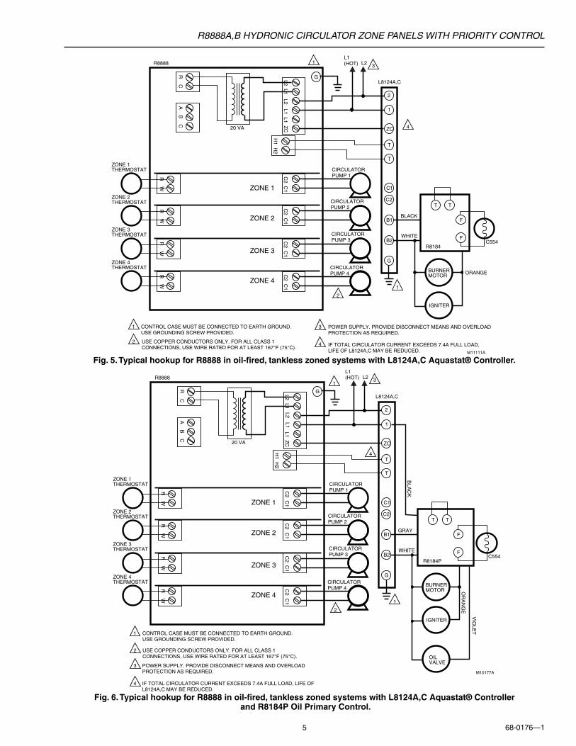
Fig. 5. Typical hookup for R8888 in oil-fired, tankless zoned systems with L8124A,C Aquastat® Controller.
Fig. 6. Typical hookup for R8888 in oil-fired, tankless zoned systems with L8124A,C Aquastat® Controller and R8184P Oil Primary Control.
C2 C
1
H1 H
2
L2 L1L1 Z
C
R W
R C
A B
C
R W
R W
R W
C2 C
1C
2 C1
C2 C
1
ZONE 1
ZONE 2
ZONE 3
ZONE 4
CIRCULATORPUMP 1
CIRCULATORPUMP 2
CIRCULATORPUMP 3
CIRCULATORPUMP 4
ZONE 1THERMOSTAT
ZONE 2THERMOSTAT
ZONE 3THERMOSTAT
ZONE 4THERMOSTAT
1
2
ZC
CONTROL CASE MUST BE CONNECTED TO EARTH GROUND.USE GROUNDING SCREW PROVIDED.
1
1
1
20 VA
M10177A
R8888
T
T T
F
F
T
C1
C2
B1
B2
G
GL8124A,C
R8184P
GRAY
BLA
CK
WHITEC554
BURNERMOTOR
IGNITER
OILVALVE
OR
AN
GE
VIO
LET
2
2
USE COPPER CONDUCTORS ONLY. FOR ALL CLASS 1 CONNECTIONS, USE WIRE RATED FOR AT LEAST 167°F (75°C).
L2 L1
3
4
4
POWER SUPPLY. PROVIDE DISCONNECT MEANS AND OVERLOADPROTECTION AS REQUIRED.
IF TOTAL CIRCULATOR CURRENT EXCEEDS 7.4A FULL LOAD, LIFE OF L8124A,C MAY BE REDUCED.
L1 (HOT) L2 3
C2 C
1
H1 H
2
L2 L1L2 L1
L1 ZC
R W
R C
A B
C
R W
R W
R W
C2 C
1C
2 C1
C2 C
1
ZONE 1
ZONE 2
ZONE 3
ZONE 4
CIRCULATORPUMP 1
CIRCULATORPUMP 2
CIRCULATORPUMP 3
CIRCULATORPUMP 4
ZONE 1THERMOSTAT
ZONE 2THERMOSTAT
ZONE 3THERMOSTAT
ZONE 4THERMOSTAT
1
2
ZC
CONTROL CASE MUST BE CONNECTED TO EARTH GROUND.USE GROUNDING SCREW PROVIDED.
1
1
1
20 VA
M11111A
R8888
T
T T
F
F
T
C1
C2
B1
B2
G
GL8124A,C
R8184
BLACK
WHITEC554
BURNERMOTOR
IGNITER
ORANGE
2
3
4
4
2
USE COPPER CONDUCTORS ONLY. FOR ALL CLASS 1 CONNECTIONS, USE WIRE RATED FOR AT LEAST 167°F (75°C).
POWER SUPPLY. PROVIDE DISCONNECT MEANS AND OVERLOADPROTECTION AS REQUIRED.
IF TOTAL CIRCULATOR CURRENT EXCEEDS 7.4A FULL LOAD, LIFE OF L8124A,C MAY BE REDUCED.
L1 (HOT) L2 3
R8888A,B HYDRONIC CIRCULATOR ZONE PANELS WITH PRIORITY CONTROL
68-0176—1 6
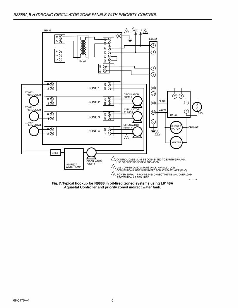
Fig. 7. Typical hookup for R8888 in oil-fired, zoned systems using L8148AAquastat Controller and priority zoned indirect water tank.
C2 C
1
H1 H
2
L2 L1L1 Z
C
R W
R C
A B
C
R W
R W
R W
C2 C
1C
2 C1
C2 C
1
ZONE 1
ZONE 2
ZONE 3
ZONE 4
CIRCULATORPUMP 2
CIRCULATORPUMP 3
CIRCULATORPUMP 4
CIRCULATORPUMP 1
ZONE 2THERMOSTAT
ZONE 3THERMOSTAT
ZONE 4THERMOSTAT
1
2
CONTROL CASE MUST BE CONNECTED TO EARTH GROUND.USE GROUNDING SCREW PROVIDED.
1
2
1
20 VA
M11112A
R8888 1
T
T T
F
F
T
C1
C2
B1
B2
G
GL8148A
R8184
BLACK
WHITEC554
BURNERMOTOR
IGNITER
ORANGE
L4006
INDIRECTWATER TANK
2
USE COPPER CONDUCTORS ONLY. FOR ALL CLASS 1 CONNECTIONS, USE WIRE RATED FOR AT LEAST 167°F (75°C).
L2 L1
3 POWER SUPPLY. PROVIDE DISCONNECT MEANS AND OVERLOADPROTECTION AS REQUIRED.
L1 (HOT) L2 3
R8888A,B HYDRONIC CIRCULATOR ZONE PANELS WITH PRIORITY CONTROL
68-0176—17
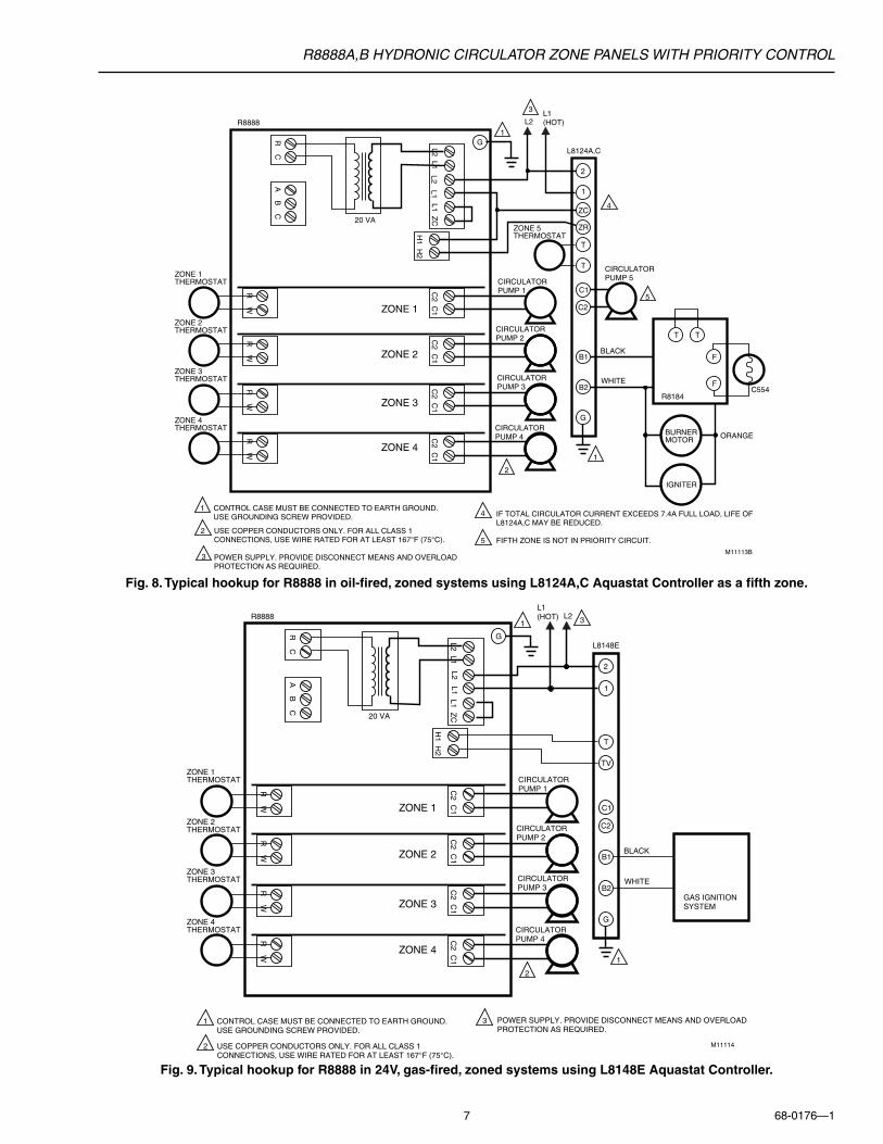
Fig. 8. Typical hookup for R8888 in oil-fired, zoned systems using L8124A,C Aquastat Controller as a fifth zone.
Fig. 9. Typical hookup for R8888 in 24V, gas-fired, zoned systems using L8148E Aquastat Controller.
C2 C
1
H1 H
2
L2 L1L1 Z
C
R W
R C
A B
C
R W
R W
R W
C2 C
1C
2 C1
C2 C
1
ZONE 1
ZONE 2
ZONE 3
ZONE 4
CIRCULATORPUMP 1
CIRCULATORPUMP 2
CIRCULATORPUMP 3
CIRCULATORPUMP 4
ZONE 1THERMOSTAT
ZONE 2THERMOSTAT
ZONE 3THERMOSTAT
ZONE 4THERMOSTAT
1
2
CONTROL CASE MUST BE CONNECTED TO EARTH GROUND.USE GROUNDING SCREW PROVIDED.
1
1
20 VA
M11114
R88881
T
TV
C1
C2
B1
B2
G
L8148E
GAS IGNITIONSYSTEM
BLACK
WHITE
2
2
USE COPPER CONDUCTORS ONLY. FOR ALL CLASS 1 CONNECTIONS, USE WIRE RATED FOR AT LEAST 167°F (75°C).
G
L2 L1
3 POWER SUPPLY. PROVIDE DISCONNECT MEANS AND OVERLOADPROTECTION AS REQUIRED.
L1 (HOT) L2 3
C2 C
1
H1 H
2
L2 L1L1 Z
C
R W
R C
A B
C
R W
R W
R W
C2 C
1C
2 C1
C2 C
1
ZONE 1
ZONE 2
ZONE 3
ZONE 4
CIRCULATORPUMP 1
CIRCULATORPUMP 5
CIRCULATORPUMP 2
CIRCULATORPUMP 3
CIRCULATORPUMP 4
ZONE 1THERMOSTAT
ZONE 5THERMOSTAT
ZONE 2THERMOSTAT
ZONE 3THERMOSTAT
ZONE 4THERMOSTAT
1
2
ZC
ZR
CONTROL CASE MUST BE CONNECTED TO EARTH GROUND.USE GROUNDING SCREW PROVIDED.
1
1
20 VA
M11113B
R88881
T
T T
F
F
T
C1
C2
B1
B2
G
GL8124A,C
R8184
BLACK
WHITEC554
BURNERMOTOR
IGNITER
ORANGE
2
2 USE COPPER CONDUCTORS ONLY. FOR ALL CLASS 1 CONNECTIONS, USE WIRE RATED FOR AT LEAST 167°F (75°C).
POWER SUPPLY. PROVIDE DISCONNECT MEANS AND OVERLOADPROTECTION AS REQUIRED.
L2 L1
3
4
4
5
5
IF TOTAL CIRCULATOR CURRENT EXCEEDS 7.4A FULL LOAD, LIFE OF L8124A,C MAY BE REDUCED.
FIFTH ZONE IS NOT IN PRIORITY CIRCUIT.
L1 (HOT)L2
3
R8888A,B HYDRONIC CIRCULATOR ZONE PANELS WITH PRIORITY CONTROL
68-0176—1 8
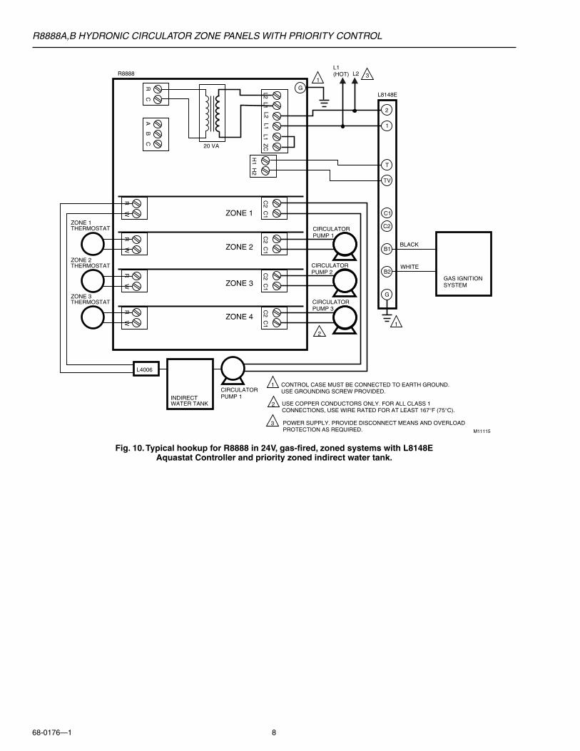
Fig. 10. Typical hookup for R8888 in 24V, gas-fired, zoned systems with L8148EAquastat Controller and priority zoned indirect water tank.
C2 C
1
H1 H
2
L2 L1L1 Z
C
R W
R C
A B
C
R W
R W
R W
C2 C
1C
2 C1
C2 C
1
ZONE 1
ZONE 2
ZONE 3
ZONE 4
CIRCULATORPUMP 1
CIRCULATORPUMP 2
CIRCULATORPUMP 3
ZONE 1THERMOSTAT
ZONE 2THERMOSTAT
ZONE 3THERMOSTAT
1
2
CONTROL CASE MUST BE CONNECTED TO EARTH GROUND.USE GROUNDING SCREW PROVIDED.
1
2
1
20 VA
M11115
R88881
T
TV
C1
C2
B1
B2
G
L8148E
GAS IGNITIONSYSTEM
BLACK
WHITE
CIRCULATORPUMP 1
L4006
INDIRECTWATER TANK
2
USE COPPER CONDUCTORS ONLY. FOR ALL CLASS 1 CONNECTIONS, USE WIRE RATED FOR AT LEAST 167°F (75°C).
G
L2 L1
3 POWER SUPPLY. PROVIDE DISCONNECT MEANS AND OVERLOADPROTECTION AS REQUIRED.
L1 (HOT) L2 3
R8888A,B HYDRONIC CIRCULATOR ZONE PANELS WITH PRIORITY CONTROL
68-0176—19
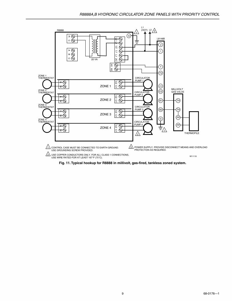
Fig. 11. Typical hookup for R8888 in millivolt, gas-fired, tankless zoned system.
C2 C
1
H1 H
2
L2 L1L1 Z
C
R W
R C
A B
C
R W
R W
R W
C2 C
1C
2 C1
C2 C
1
ZONE 1
ZONE 2
ZONE 3
ZONE 4
CIRCULATORPUMP 1
CIRCULATORPUMP 2
CIRCULATORPUMP 3
CIRCULATORPUMP 4
ZONE 1THERMOSTAT
ZONE 2THERMOSTAT
ZONE 3THERMOSTAT
ZONE 4THERMOSTAT
1
2
CONTROL CASE MUST BE CONNECTED TO EARTH GROUND.USE GROUNDING SCREW PROVIDED.
1
1
20 VA
M11116
R88881
T
TV
C1
C2
B1 TH
TH
PP
PP
B2
G
L8148B
MILLIVOLTGAS VALVE
THERMOPILE
2
2
USE COPPER CONDUCTORS ONLY. FOR ALL CLASS 1 CONNECTIONS, USE WIRE RATED FOR AT LEAST 167°F (75°C).
G
L2 L1
3 POWER SUPPLY. PROVIDE DISCONNECT MEANS AND OVERLOADPROTECTION AS REQUIRED.
L1 (HOT) L2 3
R8888A,B HYDRONIC CIRCULATOR ZONE PANELS WITH PRIORITY CONTROL
68-0176—1 10
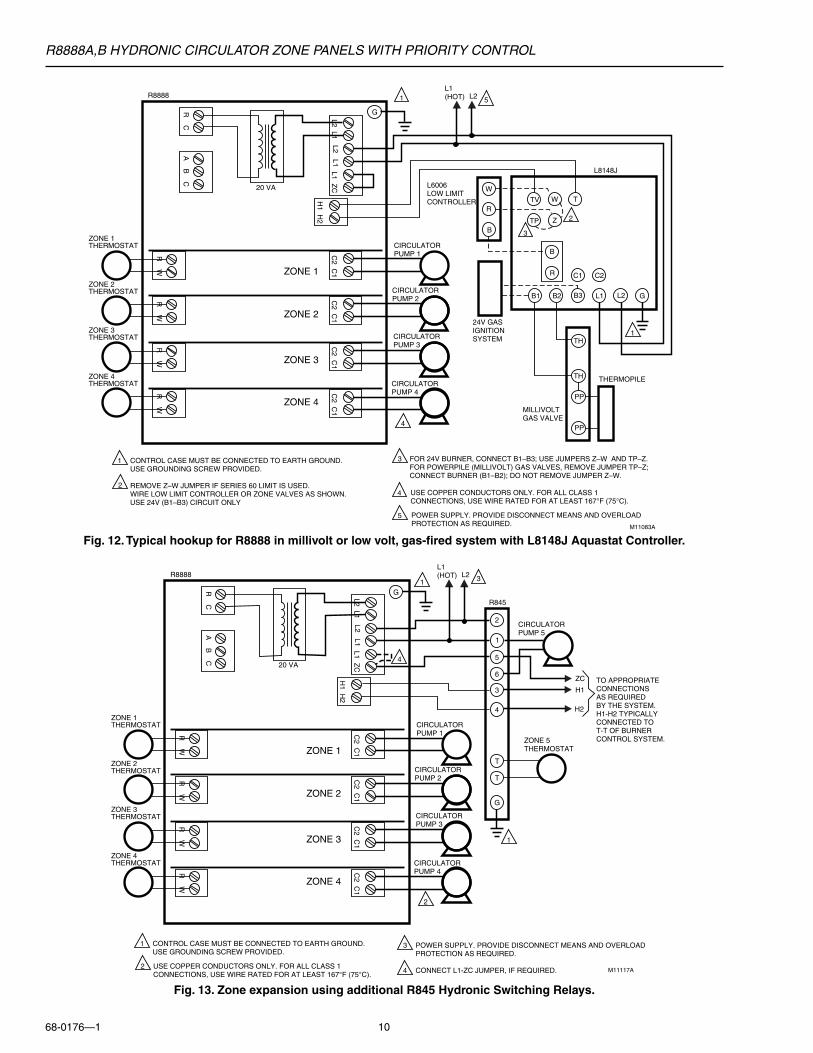
Fig. 13. Zone expansion using additional R845 Hydronic Switching Relays.
Fig. 12. Typical hookup for R8888 in millivolt or low volt, gas-fired system with L8148J Aquastat Controller.
C2 C
1
H1 H
2
L2 L1L1 Z
C
R W
R C
A B
C
R W
R W
R W
C2 C
1C
2 C1
C2 C
1
ZONE 1
ZONE 2
ZONE 3
ZONE 4
CIRCULATORPUMP 1
CIRCULATORPUMP 2
CIRCULATORPUMP 3
CIRCULATORPUMP 4
ZONE 1THERMOSTAT
ZONE 2THERMOSTAT
ZONE 3THERMOSTAT
ZONE 4THERMOSTAT
W
R
B
TH
TH
PP
PP
TV W T
TP Z
B
R C1 C2
B1 B2 B3 L1 L2 G
24V GASIGNITIONSYSTEM
L6006LOW LIMITCONTROLLER
MILLIVOLTGAS VALVE
THERMOPILE
L8148J
G
CONTROL CASE MUST BE CONNECTED TO EARTH GROUND.USE GROUNDING SCREW PROVIDED.
REMOVE Z–W JUMPER IF SERIES 60 LIMIT IS USED. WIRE LOW LIMIT CONTROLLER OR ZONE VALVES AS SHOWN.USE 24V (B1–B3) CIRCUIT ONLY
FOR 24V BURNER, CONNECT B1–B3; USE JUMPERS Z–W AND TP–Z.FOR POWERPILE (MILLIVOLT) GAS VALVES, REMOVE JUMPER TP–Z;CONNECT BURNER (B1–B2); DO NOT REMOVE JUMPER Z–W.
1
2
1
2
3
3
20 VA
M11083A
R8888 1
4
4
USE COPPER CONDUCTORS ONLY. FOR ALL CLASS 1 CONNECTIONS, USE WIRE RATED FOR AT LEAST 167°F (75°C).
L2 L1
5 POWER SUPPLY. PROVIDE DISCONNECT MEANS AND OVERLOADPROTECTION AS REQUIRED.
L1 (HOT) L2 5
C2 C
1
H1 H
2
L2 L1L1 Z
C
R W
R C
A B
C
R W
R W
R W
C2 C
1C
2 C1
C2 C
1
ZONE 1
ZONE 2
ZONE 3
ZONE 4
CIRCULATORPUMP 1
CIRCULATORPUMP 2
CIRCULATORPUMP 3
CIRCULATORPUMP 4
CIRCULATORPUMP 5
ZONE 1THERMOSTAT
ZONE 5THERMOSTAT
ZONE 2THERMOSTAT
ZONE 3THERMOSTAT
ZONE 4THERMOSTAT
1
2
4
3
6
5
CONTROL CASE MUST BE CONNECTED TO EARTH GROUND.USE GROUNDING SCREW PROVIDED.
1
1
20 VA
M11117A
R88881
G
R845
T
T
TO APPROPRIATECONNECTIONSAS REQUIRED BY THE SYSTEM.H1-H2 TYPICALLYCONNECTED TOT-T OF BURNERCONTROL SYSTEM.
ZC
H1
H2
2
2
USE COPPER CONDUCTORS ONLY. FOR ALL CLASS 1 CONNECTIONS, USE WIRE RATED FOR AT LEAST 167°F (75°C).
G
L2 L1
3
4
4
POWER SUPPLY. PROVIDE DISCONNECT MEANS AND OVERLOADPROTECTION AS REQUIRED.
CONNECT L1-ZC JUMPER, IF REQUIRED.
L1 (HOT) L2 3
R8888A,B HYDRONIC CIRCULATOR ZONE PANELS WITH PRIORITY CONTROL
68-0176—111
C2 C
1
H1 H
2
L2 L1L1 Z
C
R W
R C
A B
C
R W
R W
R W
C2 C
1C
2 C1
C2 C
1
ZONE 1
ZONE 2
ZONE 3
ZONE 4
CIRCULATORPUMP 2
CIRCULATORPUMP 3
CIRCULATORPUMP 4
CIRCULATORPUMP 1
ZONE 2THERMOSTAT
ZONE 1THERMOSTAT
ZONE 3THERMOSTAT
ZONE 4THERMOSTAT
ZONE 6THERMOSTAT
ZONE 5THERMOSTAT
ZONE 7THERMOSTAT
ZONE 8THERMOSTAT
L1
L2
ZC
CONTROL CASE MUST BE CONNECTED TO EARTH GROUND.USE GROUNDING SCREW PROVIDED.
1
2
CIRCULATORPUMP 6
CIRCULATORPUMP 7
CIRCULATORPUMP 8
CIRCULATORPUMP 5
2
1
20 VA
M11118B
R8888
C2 C
1
H1 H
2
L2 L1L2 L1
L1 ZC
R W
R C
A B
C
R W
R W
R W
C2 C
1C
2 C1
C2 C
1
ZONE 1
ZONE 2
ZONE 3
ZONE 4
20 VA
R8888
1
1
1
5
6
T
T T
F
F
T
C1
C2
B1
B2
G
L8124A,C
T
T
6
5
4
3
2
1
G
R845A
R8184
BLACK
WHITEC554
BURNERMOTOR
IGNITER
ORANGE
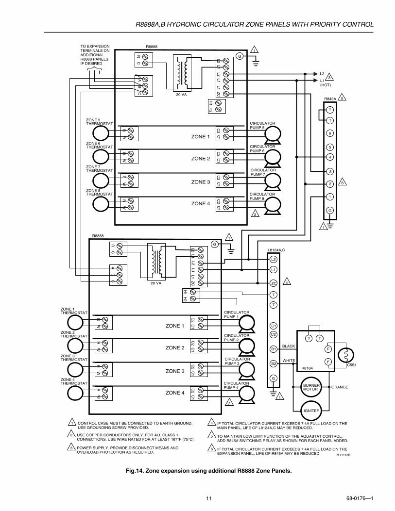
2 USE COPPER CONDUCTORS ONLY. FOR ALL CLASS 1 CONNECTIONS, USE WIRE RATED FOR AT LEAST 167°F (75°C).
POWER SUPPLY. PROVIDE DISCONNECT MEANS AND OVERLOAD PROTECTION AS REQUIRED.
G
G
TO EXPANSIONTERMINALS ON ADDITIONALR8888 PANELS IF DESIRED
L2 L1
4
3
5
6
4
IF TOTAL CIRCULATOR CURRENT EXCEEDS 7.4A FULL LOAD ON THE MAIN PANEL, LIFE OF L8124A,C MAY BE REDUCED.
TO MAINTAIN LOW LIMIT FUNCTION OF THE AQUASTAT CONTROL,ADD R845A SWITCHING RELAY AS SHOWN FOR EACH PANEL ADDED.
IF TOTAL CIRCULATOR CURRENT EXCEEDS 7.4A FULL LOAD ON THEEXPANSION PANEL, LIFE OF R845A MAY BE REDUCED.
L1 (HOT)
L23
Fig.14. Zone expansion using additional R8888 Zone Panels.
R8888A,B HYDRONIC CIRCULATOR ZONE PANELS WITH PRIORITY CONTROL
68-0176—1 12
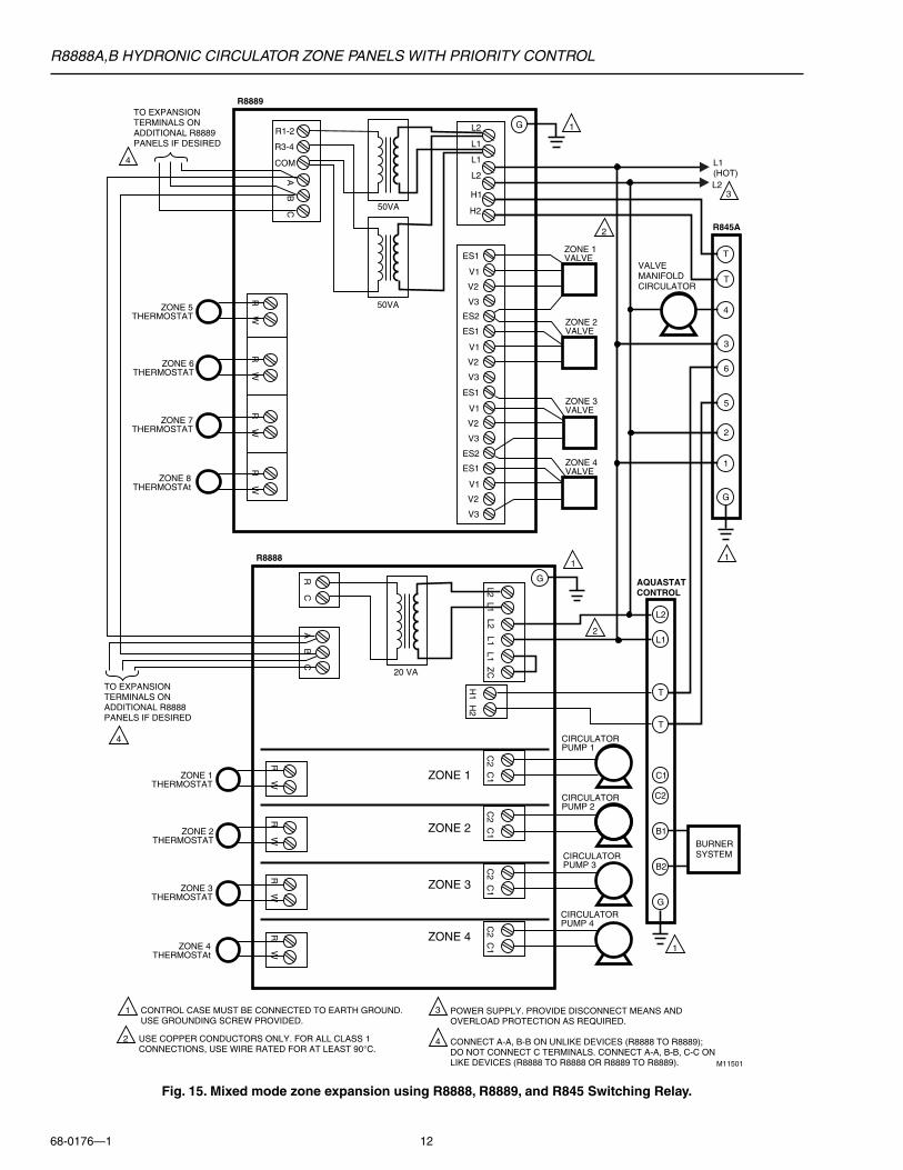
Fig. 15. Mixed mode zone expansion using R8888, R8889, and R845 Switching Relay.
C2 C
1
H1 H
2
L2 L1L1 Z
C
R W
R C
A B
C
R W
R W
R W
C2 C
1C
2 C1
C2 C
1
ZONE 1
ZONE 2
ZONE 3
ZONE 4
CIRCULATORPUMP 2
CIRCULATORPUMP 3
CIRCULATORPUMP 4
CIRCULATORPUMP 1
L1
L2
CONTROL CASE MUST BE CONNECTED TO EARTH GROUND.USE GROUNDING SCREW PROVIDED.
1
2
ZONE 1VALVE
ZONE 2VALVE
ZONE 3VALVE
ZONE 4VALVE
2
1
20 VA
M11501
R8888
R W
A B
C
R W
R W
R W
R8889
50VA
50VA
11
1
T
T
C1
C2
B1
B2
G
AQUASTAT CONTROL
T
T
6
5
4
3
2
1
G
R845A
2 USE COPPER CONDUCTORS ONLY. FOR ALL CLASS 1 CONNECTIONS, USE WIRE RATED FOR AT LEAST 90°C.
G
GTO EXPANSIONTERMINALS ON ADDITIONAL R8889 PANELS IF DESIRED
TO EXPANSIONTERMINALS ON ADDITIONAL R8888 PANELS IF DESIRED
L2 L1
3
4
4
POWER SUPPLY. PROVIDE DISCONNECT MEANS AND OVERLOAD PROTECTION AS REQUIRED.
CONNECT A-A, B-B ON UNLIKE DEVICES (R8888 TO R8889);DO NOT CONNECT C TERMINALS. CONNECT A-A, B-B, C-C ON LIKE DEVICES (R8888 TO R8888 OR R8889 TO R8889).
L1 (HOT)L2
3
R1-2
R3-4
COM
ES1
V1
V2
V3
ES1
V1
V2
V3
ES1
V1
V2
V3
ES1
V1
V2
V3
ES2
ES2
L1
L1
L2
L2
H1
H2
VALVEMANIFOLDCIRCULATOR
BURNERSYSTEM
ZONE 6THERMOSTAT
ZONE 5THERMOSTAT
ZONE 7THERMOSTAT
ZONE 8THERMOSTAt
ZONE 2THERMOSTAT
ZONE 1THERMOSTAT
ZONE 3THERMOSTAT
ZONE 4THERMOSTAt
4
R8888A,B HYDRONIC CIRCULATOR ZONE PANELS WITH PRIORITY CONTROL
68-0176—113
OPERATION
OverviewThe R8888 Hydronic Circulator Zone Panel with PriorityControl can control up to three or four (depending on model)zone circulator pumps. Additional zones may be added one ata time using an R845 Hydronic Switching Relay for eachadditional zone or three or four zones at a time usingadditional R8888A or B Zone Panels, respectively.
Line voltage power connected to L1 and L2 on the R8888Panel provides power to the 24V transformer. Thistransformer provides 24 Vac power to the R8888 Panel. Agreen light-emitting diode (LED) on the panel indicates thatthere is 24 Vac power applied to the R8888 Panel.
When a zone thermostat calls for heat during standardoperation, the R and W terminals make for that zonethermostat. The relay for that zone is energized and the LEDfor that zone comes on. The burner relay is also energizedand the H1 and H2 terminals make. The circulator relay forthat zone is energized, providing line voltage between the C1and C2 terminals, (energizing that zone circulator pump).
Each zone operates in the same sequence described above.As long as any zone is calling for heat, the burner relay isenergized.
Priority Zoning OperationThe R8888 allows Zone 1 to be field-configured as a priority ornon-priority zone. Zone 1 is factory-set as a priority zone. (Referto Fig. 2 for location and settings of the priority enable andburner control switches.) This feature is typically used ininstallations where indirect hot water tanks are installed. Whenconfigured in this manner, a call for heat from the priority zonedisables the circulators on the other three zones, assuringmaximum heat transfer to the hot water tank. Normal control ofthe non-prioritized zones returns when the priority zone call forheat ends. Since this feature is field-configurable, it can bedisabled, giving equal priority to all four zones. Refer to Fig. 7(oil-fired) and Fig. 10 (gas-fired) for typical wiring connections.Note that the LED for each zone remains on as long as a callfor heat remains for that zone, even though the priority zonecan cause its circulator relay to be de-energized.
NOTE When a power stealing thermostat is used in a non-priority zone, the heat call LED for that zoneilluminates slightly under the folowing conditions:• The power stealing thermostat is in the OFF
state.• PRIORITY ENABLE is ON.• The priority zone is calling for heat.
Burner Control OperationThe R8888 allows Zone 2 burner control to be disabled.Zone 2 is factory-set for normal burner control. (Refer to Fig. 2for location and settings of the priority enable and burnercontrol switches.) This feature may be used to prevent shortcycling the boiler in installations where both small and largezones exist in close proximity. In these applications, if allzones have normal burner control, a call for heat from thesmall zone is satisfied quickly and the boiler short cycles. Byswitching the burner control from NORMAL to OFF, a call forheat results in only its circulator pump running. Often thelatent heat in the boiler and pipes alone satisfies the smallzone. If necessary, the larger zone brings on the boiler beforetoo long due to the proximity of the zones.
Cold Start Boiler Operation (Fig. 7-10)The R8888 may be applied to boilers using either the L8124(high and low limit) or the L8148 (high limit only) AquastatControllers. When using the L8148, the boiler runs only whenthere is a call for heat from an external thermostat. Fig. 7through 10 illustrate typical wiring connections for thisapplication. Do not remove the factory-installed jumperbetween the L1 and Zc terminals. Fig. 8 illustrates a methodof obtaining a fifth zone by using the Aquastat controller. Notethat this hookup removes power from the thermostatwhenever the limit opens.
IMPORTANTDo not use power stealing electronic thermostats inthis application. Use battery powered thermostats orthe T87 Round® Thermostat.
Tankless Coil Boiler Operation (Fig. 5)When using the L8124, the R8888 may be connected so allzone circulators are disabled when the low limit opens. Thisallows the boiler water to reach minimum temperature beforetransferring heat to any zones. This is acomplished as powerto all of the circulator relay contacts goes to terminal Zc.Remove the R8888 factory-installed jumper between the L1and Zc terminals. Connect the Zc terminal from the R8888 tothe Zc terminal on the L8124. When the L8124 senses thatthe boiler is below the low limit, it removes power from the Zcterminal.
To aid in troubleshooting, a green LED (LOW LIMIT) isprovided. This LED illuminates whenever the power to thecirculator relay contacts is available from the Zc terminal.
R8888A,B HYDRONIC CIRCULATOR ZONE PANELS WITH PRIORITY CONTROL
68-0176—1 14
When using multiple panels, set the PANEL TYPE switch onone panel to the MAIN position. Zone 1 on this panel is thepriority zone for the system. Set the other panels to theEXPANSION position. Set the PRIORITY ENABLE switch tothe same position on all panels.
Thermostat CompatibilityThe R8888 is compatible with both electromechanical andelectronic thermostats. In the thermostat Off state, the R8888allows up to 0.12A to be drawn, satisfying the trickle chargerequirement of power-stealing electronic thermostats. In thethermostat On state, the R8888 provides 0.12A to satisfy theanticipator current requirement of all electromechanical andmany electronic thermostats.
SERVICE AND CHECKOUT
CAUTIONDisconnect power supply before removing cover forservicing to prevent electrical shock or equipmentdamage.
1. Remove the R8888 cover.2. With the cover removed, reconnect power to R8888
Zone Panel.3. Check for power across L1 and L2 terminals using a
voltmeter.4. Check that green 24 Vac power LED lights, indicating
24 Vac power to low voltage circuit.
CAUTIONIf transformer fails and LED does not light, line voltagecan continue to be present at L1 and L2 terminals.Check for power using a voltmeter.
5. If the transformer is determined defective, replace itwith Honeywell part no. AT20A1123.
6. During checkout, jumper thermostat R-W terminals onR8888 separately for each zone. The green LED for thatzone lights, simulating a call for heat from the zonethermostat.
ExpansionExpansion Using an Aquastat Control (Fig. 8)Control of a fifth zone can be obtained by using an Aquastatcontrol. This hookup causes additional wear on the Aquastatlow limit because the switch must remove power from all thecirculators in the system when it switches off to allow theboiler temperature to recover. Zone expansion usingadditional R8888s or R845 Switching Relays isrecommended.
NOTE: This hookup removes power from the thermostatwhenever the limit opens. Do not use power stealingelectronic thermostats. Use battery poweredthermostats or the T87 Round® Thermostat.
Expansion Using R845 Switching Relays (Fig.13)The R8888 can be expanded one zone at a time by usingR845 Switching Relays. The priority zone is not maintained inthis hookup.
Expansion Using Additional R8888s or R8889s(Fig.14-15)The R8888 can be expanded thress or four zones at a timeusing additional R8888 or R8889 Zone Panels. Up to fourzone panels (12 to 16 zones total) may be added to a system.Connect the system burner to the burner terminals on theAquastat Control. When using the additional zone panels, thepriority zone is maintained. The burner control function onZone 2 of the R8888 is not affected during expansion.
When wiring additional R8888s, connect the wires from thethree expansion terminals (A,B,C) on one zone panel to theexpansion terminals on the next zone panel. For each paneladded, connect an R845A as shown in Fig. 14 to maintain thelow limit function. Run wires through the knockouts on thesides of the zone panels (see Fig. 4).
When running a mixed mode system (R8888-R8889combination), connect an R845A as shown in Fig. 15.Connect the wires from the expansion terminals (A,B,C) onone zone panel to the expansion terminals (A,B,C) on thenext zone panel. Connect A to A, B to B, and C to C on likepanels (R8888 connected to R8888, R8889 connected toR8889). Do not connect the C terminals when connecting anR8888 to an R8889.
R8888A,B HYDRONIC CIRCULATOR ZONE PANELS WITH PRIORITY CONTROL
68-0176—115
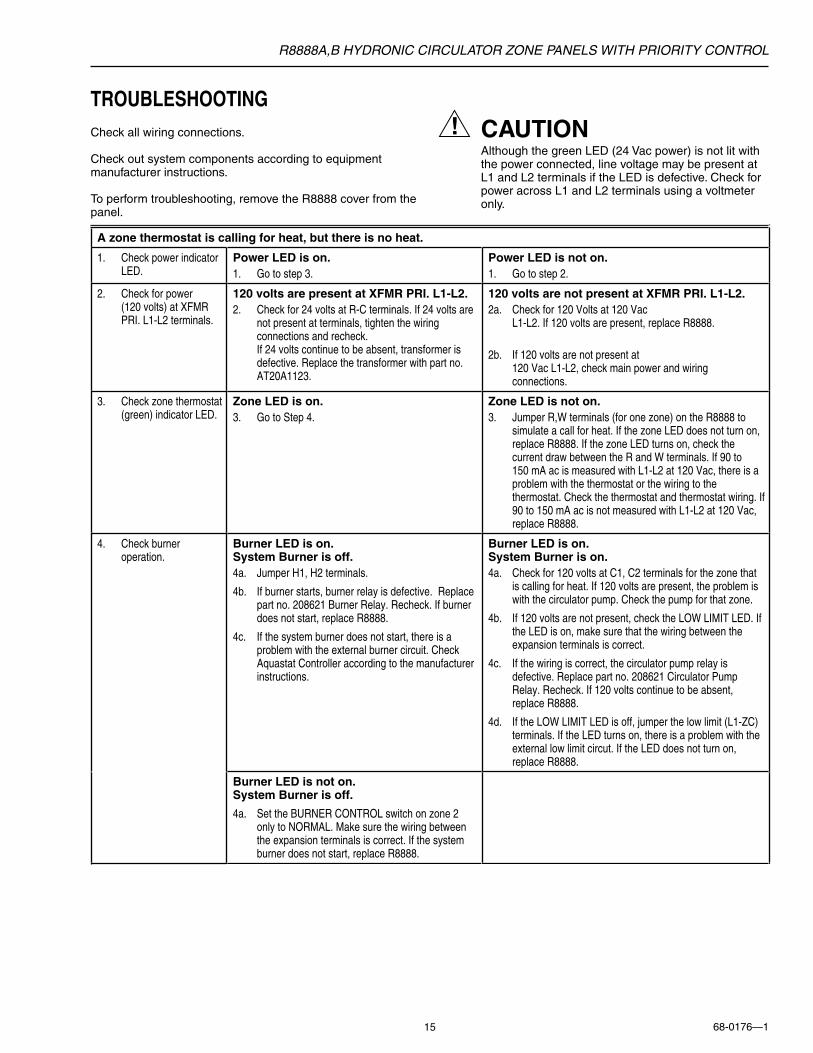
TROUBLESHOOTINGCheck all wiring connections.
Check out system components according to equipmentmanufacturer instructions.
To perform troubleshooting, remove the R8888 cover from thepanel.
CAUTIONAlthough the green LED (24 Vac power) is not lit withthe power connected, line voltage may be present atL1 and L2 terminals if the LED is defective. Check forpower across L1 and L2 terminals using a voltmeteronly.
A zone thermostat is calling for heat, but there is no heat.
1. Check power indicatorLED.
Power LED is on.1. Go to step 3.
Power LED is not on.1. Go to step 2.
2. Check for power (120 volts) at XFMRPRI. L1-L2 terminals.
120 volts are present at XFMR PRI. L1-L2.2. Check for 24 volts at R-C terminals. If 24 volts are
not present at terminals, tighten the wiringconnections and recheck. If 24 volts continue to be absent, transformer isdefective. Replace the transformer with part no.AT20A1123.
120 volts are not present at XFMR PRI. L1-L2.2a. Check for 120 Volts at 120 Vac
L1-L2. If 120 volts are present, replace R8888.
2b. If 120 volts are not present at 120 Vac L1-L2, check main power and wiringconnections.
3. Check zone thermostat(green) indicator LED.
Zone LED is on.3. Go to Step 4.
Zone LED is not on.3. Jumper R,W terminals (for one zone) on the R8888 to
simulate a call for heat. If the zone LED does not turn on,replace R8888. If the zone LED turns on, check thecurrent draw between the R and W terminals. If 90 to 150 mA ac is measured with L1-L2 at 120 Vac, there is aproblem with the thermostat or the wiring to thethermostat. Check the thermostat and thermostat wiring. If90 to 150 mA ac is not measured with L1-L2 at 120 Vac,replace R8888.
4. Check burneroperation.
Burner LED is on.System Burner is off.4a. Jumper H1, H2 terminals.
4b. If burner starts, burner relay is defective. Replacepart no. 208621 Burner Relay. Recheck. If burnerdoes not start, replace R8888.
4c. If the system burner does not start, there is aproblem with the external burner circuit. CheckAquastat Controller according to the manufacturerinstructions.
Burner LED is on.System Burner is on.4a. Check for 120 volts at C1, C2 terminals for the zone that
is calling for heat. If 120 volts are present, the problem iswith the circulator pump. Check the pump for that zone.
4b. If 120 volts are not present, check the LOW LIMIT LED. Ifthe LED is on, make sure that the wiring between theexpansion terminals is correct.
4c. If the wiring is correct, the circulator pump relay isdefective. Replace part no. 208621 Circulator PumpRelay. Recheck. If 120 volts continue to be absent,replace R8888.
4d. If the LOW LIMIT LED is off, jumper the low limit (L1-ZC)terminals. If the LED turns on, there is a problem with theexternal low limit circut. If the LED does not turn on,replace R8888.
Burner LED is not on.System Burner is off.
4a. Set the BURNER CONTROL switch on zone 2only to NORMAL. Make sure the wiring betweenthe expansion terminals is correct. If the systemburner does not start, replace R8888.

R8888A,B HYDRONIC CIRCULATOR ZONE PANELS WITH PRIORITY CONTROL
68-0176—1 16
Honeywell Europe S.A.3 Avenue du Bourget1140 BrusselsBelgium
Honeywell Asia Pacific Inc.Room 3213-3225Sun Hung Kai CentreNo. 30 Harbour RoadWanchaiHong Kong
Home and Building ControlHoneywell Limited-Honeywell Limitée155 Gordon Baker RoadNorth York, OntarioM2H 3N7
Honeywell Latin American Region480 Sawgrass Corporate ParkwaySuite 200Sunrise FL 33325
Helping You Control Your World®
68-0176—1 C.H. Rev. 8-97 Printed in U.S.A.
Home and Building ControlHoneywell Inc.Honeywell PlazaP.O. Box 524Minneapolis MN 55408-0524
A zone thermostat is not calling for heat, but there is heat.
1. Check burneroperation.
Burner LED is not on.System Burner is on.
4a. Remove burner relay. If the system turns off,burner relay is defective. Replace part no. 208621Burner Relay.
4b. If the system burner is on, remove the field wirefrom H1 terminal. If the system burner is still on,the problem is with the external system burnercircuit. If system burner turns off, replace R8888.
www.honeywell.com/building/components