Embed Size (px)
Citation preview
GRUNDFOS Pumps Corporation 17100 West 118th TerraceOlathe, Kansas 66061Phone: +1-913-227-3400 Telefax: +1-913-227-3500
GRUNDFOS Canada Inc. 2941 Brighton Road Oakville, Ontario L6H 6C9 CanadaPhone: +1-905 829 9533 Telefax: +1-905 829 9512
Bombas GRUNDFOS de Mexico S.A. de C.V. Boulevard TLC No. 15Parque Industrial Stiva AeropuertoApodaca, N.L. Mexico 66600Phone: +52-81-8144 4000 Telefax: +52-81-8144 4010
www.grundfos.com
L-TP-PG-001 08/07USRepl. L-TP-PG-001 12/06
PRINTED IN USA Subject to alterations.
Being responsible is our foundationThinking ahead makes it possible
Innovation is the essence
TPVersaFlo.book Page 28 Monday, August 20, 2007 3:55 PM
GRUNDFOS PRODUCT GUIDE
VersaFlo®
TP circulator pumps60 Hz
TPVersaFlo.book Page 1 Monday, August 20, 2007 3:55 PM
2
Contents
Mission
General dataCross reference guide: B&G, Taco and Armstrong to Grundfos 4Performance range, TP 5Product range, TP 6Type key, TP 6Applications 6Construction, TP 7TP technical data 7Material specification, TP 7Sectional drawing, TP 7Motor 8Pump 8Surface treatment 8Motor stool 8Pump shaft 8Coupling 8Impeller 8Shaft seal 8Space requirements 9Pumped liquids 9Liquid temperature 9List of pumped liquids 9Legend for notes in the list 9
Performance curvesTP 32-XX 12TP 40-XX 14TP 50-XX 16TP 80-XX 18TP 100-XX 20
Data chartsVersaFlo®TP 22VersaFlo® UPS/TP packaged flange sets´ 23VersaFlo® TP optional shaft seal kits 23
Submittal data sheetSubmittal data sheet 24
Further product documentationWebCAPS 25WinCAPS 26
TPVersaFlo.book Page 2 Monday, August 20, 2007 3:55 PM
27
TPVersaFlo.book Page 27 Monday, August 20, 2007 3:55 PM
Further product documentation
VersaFlo® TP
26
WinCAPS
Fig. 5 WinCAPS CD-ROM
WinCAPS is a Windows-based Computer Aided Product Selection program containing detailed informa-tion on more than 185,000 Grundfos products in more than 22 languages.
The program contains the same features and functions as WebCAPS, but is an ideal solution if no Internet connection is available.
WinCAPS is available on CD-ROM and updated once a year.
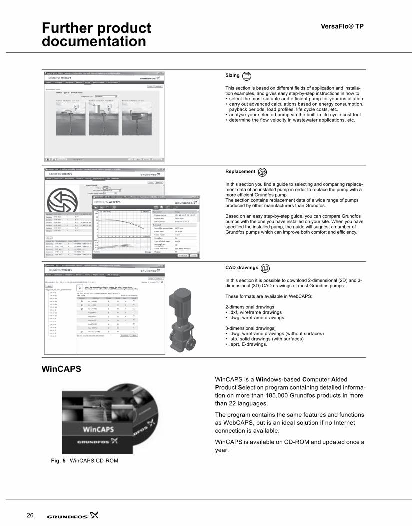
Sizing
This section is based on different fields of application and installa-tion examples, and gives easy step-by-step instructions in how to• select the most suitable and efficient pump for your installation• carry out advanced calculations based on energy consumption,
payback periods, load profiles, life cycle costs, etc.• analyse your selected pump via the built-in life cycle cost tool• determine the flow velocity in wastewater applications, etc.
Replacement
In this section you find a guide to selecting and comparing replace-ment data of an installed pump in order to replace the pump with a more efficient Grundfos pump. The section contains replacement data of a wide range of pumps produced by other manufacturers than Grundfos.
Based on an easy step-by-step guide, you can compare Grundfos pumps with the one you have installed on your site. When you have specified the installed pump, the guide will suggest a number of Grundfos pumps which can improve both comfort and efficiency.
CAD drawings
In this section it is possible to download 2-dimensional (2D) and 3-dimensional (3D) CAD drawings of most Grundfos pumps.
These formats are available in WebCAPS:
2-dimensional drawings:• .dxf, wireframe drawings• .dwg, wireframe drawings.
3-dimensional drawings:• .dwg, wireframe drawings (without surfaces)• .stp, solid drawings (with surfaces)• .eprt, E-drawings.
0 1
TPVersaFlo.book Page 26 Monday, August 20, 2007 3:55 PM
VersaFlo® TP
3
Mission
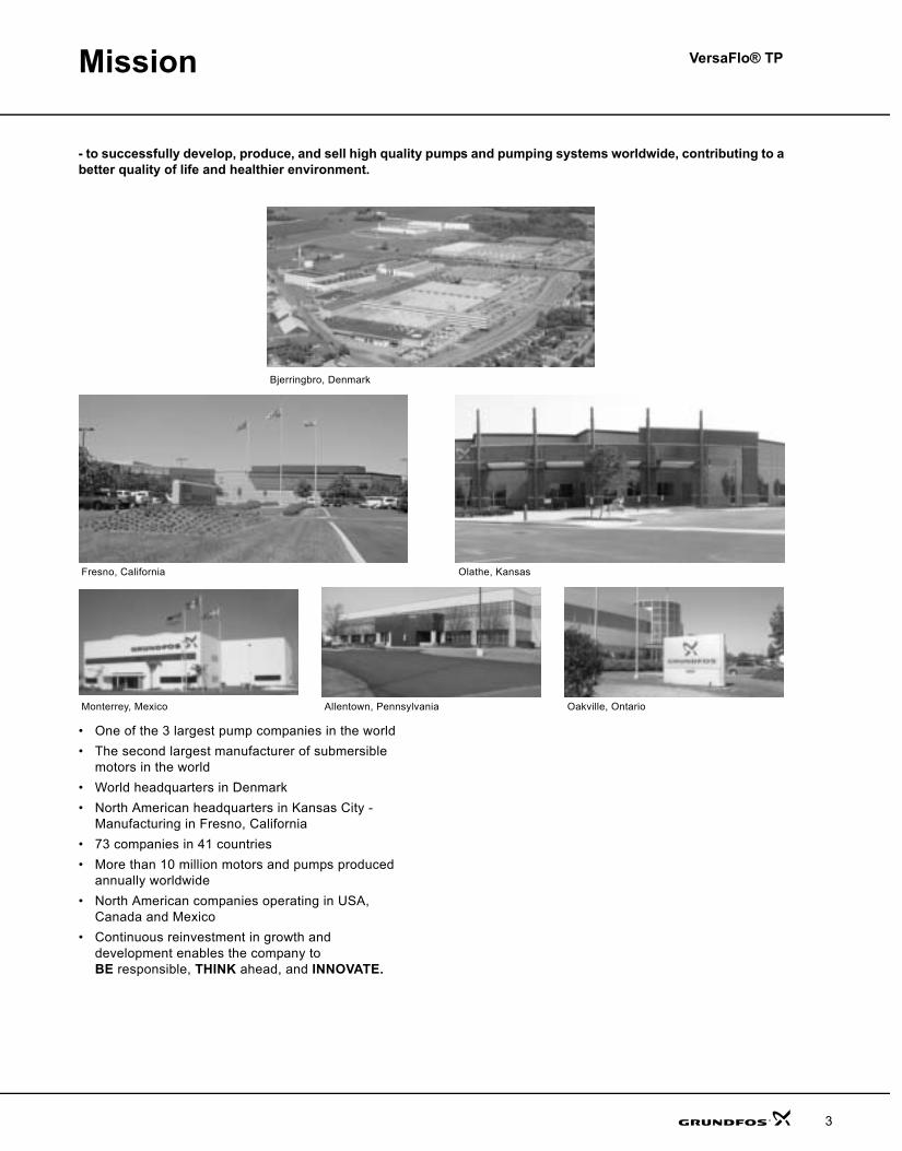
- to successfully develop, produce, and sell high quality pumps and pumping systems worldwide, contributing to a better quality of life and healthier environment.
• One of the 3 largest pump companies in the world• The second largest manufacturer of submersible
motors in the world• World headquarters in Denmark• North American headquarters in Kansas City -
Manufacturing in Fresno, California• 73 companies in 41 countries• More than 10 million motors and pumps produced
annually worldwide• North American companies operating in USA,
Canada and Mexico• Continuous reinvestment in growth and
development enables the company toBE responsible, THINK ahead, and INNOVATE.
Bjerringbro, Denmark
Fresno, California Olathe, Kansas
Monterrey, Mexico Allentown, Pennsylvania Oakville, Ontario
TPVersaFlo.book Page 3 Monday, August 20, 2007 3:55 PM
VersaFlo® TP
4
General data
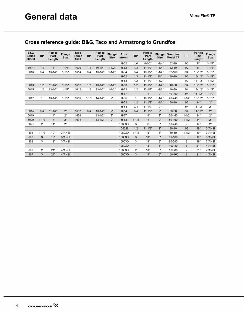
Cross reference guide: B&G, Taco and Armstrong to Grundfos
B&G Series 60&80
HPPort to
Port Length
Flange Size
Taco Series 1600
HPPort to
Port Length
Flange Size
Arm-strong HP
Port to Port
LengthFlange
SizeGrundfosModel TP HP
Port to Port
LengthFlange
Size
H-32 1/6 8-1/2" 1-1/4" 32-40 1/3 11" 1-1/4"6011 1/4 11" 1-1/4" 1600 1/4 10-1/4" 1-1/2" H-52 1/3 11-1/2" 1-1/4" 32-80 1/2 11" 1-1/4"6016 3/4 13-1/2" 1-1/2" 1614 3/4 13-1/2" 1-1/2" H-64 3/4 13-1/2" 1-1/2" 32-160 3/4 13-1/2" 1-1/2"
H-52 1/3 11-1/2" 1/4" 40-40 1/3 13-1/2" 1-1/2"H-53 1/2 11-1/2" 1-1/2" 1/2 13-1/2" 1-1/2
6013 1/2 11-1/2" 1-1/2" 1612 1/2 13-1/2" 1-1/2" H-53 1/2 11-1/2" 1-1/2" 40-80 3/4 13-1/2" 1-1/2"6015 1/2 13-1/2" 1-1/2" 1612 1/2 13-1/2" 1-1/2" H-63 1/2 13-1/2" 1-1/2" 40-80 3/4 13-1/2" 1-1/2"
H-67 1 14" 2" 40-160 3/4 11-1/2" 1-1/2"6017 1 13-1/2" 1-1/2" 1616 1-1/2 14-1/2" 2" H-65 1 13-1/2" 1-1/2" 40-240 1-1/2 13-1/2" 1-1/2"
H-53 1/2 11-1/2" 1-1/2" 50-40 1/3 14" 2"H-54 3/4 11-1/2" 2" 3/4 11-1/2" 2"
6014 3/4 11-1/2" 2" 1632 3/4 13-1/2" 2" H-54 3/4 11-1/2" 2" 50-80 3/4 11-1/2" 2"6019 1 14" 2" 1634 1 13-1/2" 2" H-67 1 14" 2" 50-160 1-1/2 14" 2"6020 1-1/2 14" 2" 1634 1 13-1/2" 2" H-68 1-1/2 14" 2" 50-160 1-1/2 14" 2"6021 2 14" 2" 10603D 3 18 3" 50-240 2 14" 2"
105028 1/2 11-1/2" 2" 80-40 1/2 19" 3"ANSI801 1-1/2 19" 3"ANSI 10603D 1-1/2 18" 3" 80-80 1-1/2 19" 3"ANSI802 3 19" 3"ANSI 10603D 3 18" 3" 80-160 3 19" 3"ANSI803 3 19" 3"ANSI 10603D 3 18" 3" 80-240 3 19" 3"ANSI
10603D 1 18" 3" 100-40 1 21" 4"ANSI806 2 21" 4"ANSI 10603D 2 18" 3" 100-80 2 21" 4"ANSI807 3 21" 4"ANSI 10603D 3 18" 3" 100-160 3 21" 4"ANSI
TPVersaFlo.book Page 4 Monday, August 20, 2007 3:55 PM
VersaFlo® TP
25
Further product documentation
WebCAPSWebCAPS is a Web-based Computer Aided Product Selection program available on www.grundfos.com.
WebCAPS contains detailed information on more than 185,000 Grundfos products in more than 22 languages.
In WebCAPS, all information is divided into 6 sections:
• Catalogue• Literature• Service• Sizing• Replacement• CAD drawings.
Catalogue
This section is based on fields of application and pump types, and contains • technical data• curves (QH, Eta, P1, P2, etc) which can be adapted to the den-
sity and viscosity of the pumped liquid and show the number of pumps in operation
• product photos• dimensional drawings• wiring diagrams• quotation texts, etc.
Literature
In this section you can access all the latest documents of a given pump, such as• data booklets• installation and operating instructions• service documentation, such as Service kit catalogue and
Service kit instructions• quick guides• product brochures, etc.
Service
This section contains an easy-to-use interactive service catalogue. Here you can find and identify service parts of both existing and dis-continued Grundfos pumps.Furthermore, this section contains service videos showing you how to replace service parts.
TPVersaFlo.book Page 25 Monday, August 20, 2007 3:55 PM
VersaFlo® TP
24
Submittal data sheet
Submittal data sheet
Company name:Prepared by:
Phone number: ( ) -Fax number: ( ) -
Submittal Data Sheet Date: Page 1 of:Quote number:
Project title: Client name:Reference number: Client number:
Client contact: Client phone no: ( ) -
For: Unit:Site: Service:
Address: City: State: Zip Code:
Technical Data Motor InformationFlow (GPM) HP:Head (Ft) Phase:Motor Voltage:Max Fluid Temp Enclosure:Min Fluid TempMax Working PressureMin Required Inlet PressureConnection Type and Size
Model Information from Type Key and Codes:Quantity Required: Example: UP-S-15-58-FC
Minimum required flow: NPSH required at duty point:Product Guide additional information pages
Materials page number: Performance curve page number:Technical data page number: Motor data page number:
Custom-built pump information (optional):
Location Information
Client Information
Additional Information
Pump Information
TP-40-160/2
TPVersaFlo.book Page 24 Monday, August 20, 2007 3:55 PM
General data VersaFlo® TP
5
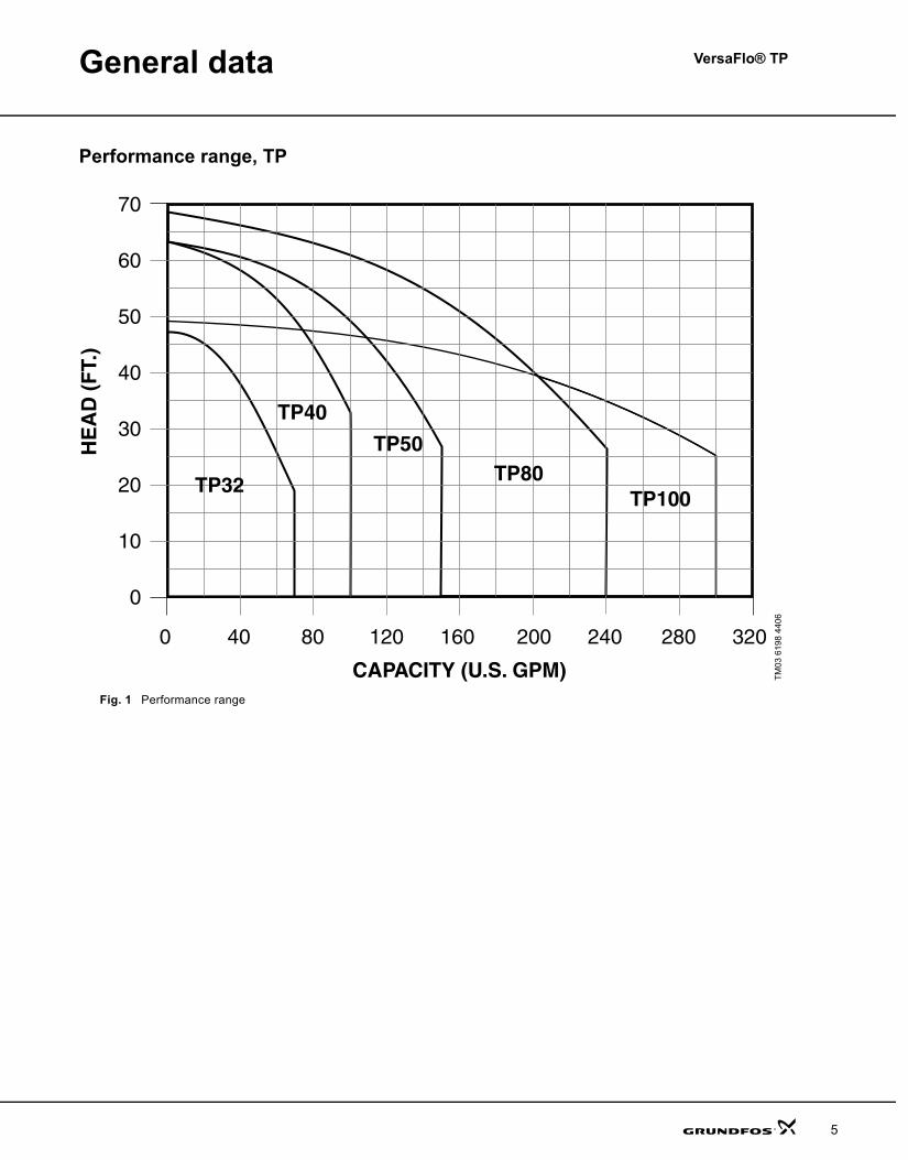
Performance range, TP
Fig. 1 Performance range
TM03
619
8 44
06
TPVersaFlo.book Page 5 Monday, August 20, 2007 3:55 PM
General data VersaFlo® TP
6
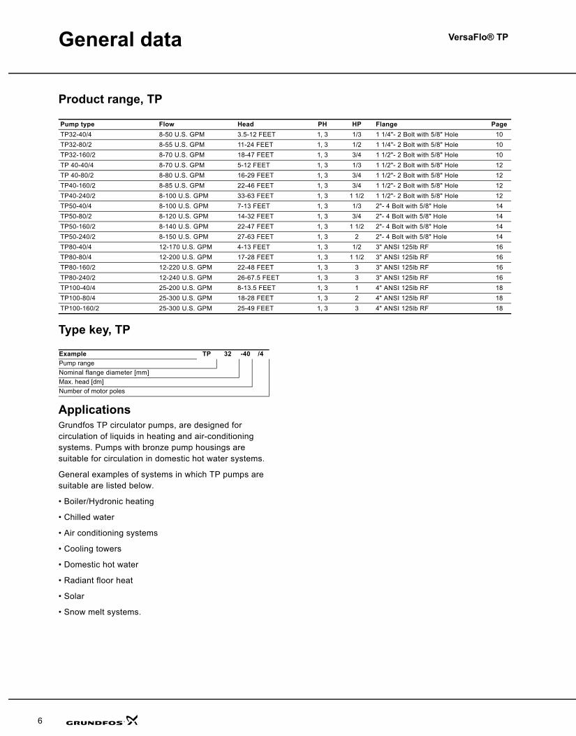
Product range, TP
Type key, TP
ApplicationsGrundfos TP circulator pumps, are designed for circulation of liquids in heating and air-conditioning systems. Pumps with bronze pump housings are suitable for circulation in domestic hot water systems.
General examples of systems in which TP pumps are suitable are listed below.
• Boiler/Hydronic heating
• Chilled water
• Air conditioning systems
• Cooling towers
• Domestic hot water
• Radiant floor heat
• Solar
• Snow melt systems.
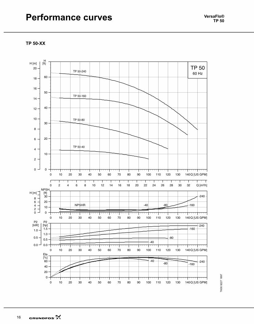
Pump type Flow Head PH HP Flange PageTP32-40/4 8-50 U.S. GPM 3.5-12 FEET 1, 3 1/3 1 1/4"- 2 Bolt with 5/8" Hole 10TP32-80/2 8-55 U.S. GPM 11-24 FEET 1, 3 1/2 1 1/4"- 2 Bolt with 5/8" Hole 10TP32-160/2 8-70 U.S. GPM 18-47 FEET 1, 3 3/4 1 1/2"- 2 Bolt with 5/8" Hole 10TP 40-40/4 8-70 U.S. GPM 5-12 FEET 1, 3 1/3 1 1/2"- 2 Bolt with 5/8" Hole 12TP 40-80/2 8-80 U.S. GPM 16-29 FEET 1, 3 3/4 1 1/2"- 2 Bolt with 5/8" Hole 12TP40-160/2 8-85 U.S. GPM 22-46 FEET 1, 3 3/4 1 1/2"- 2 Bolt with 5/8" Hole 12TP40-240/2 8-100 U.S. GPM 33-63 FEET 1, 3 1 1/2 1 1/2"- 2 Bolt with 5/8" Hole 12TP50-40/4 8-100 U.S. GPM 7-13 FEET 1, 3 1/3 2"- 4 Bolt with 5/8" Hole 14TP50-80/2 8-120 U.S. GPM 14-32 FEET 1, 3 3/4 2"- 4 Bolt with 5/8" Hole 14TP50-160/2 8-140 U.S. GPM 22-47 FEET 1, 3 1 1/2 2"- 4 Bolt with 5/8" Hole 14TP50-240/2 8-150 U.S. GPM 27-63 FEET 1, 3 2 2"- 4 Bolt with 5/8" Hole 14TP80-40/4 12-170 U.S. GPM 4-13 FEET 1, 3 1/2 3" ANSI 125lb RF 16TP80-80/4 12-200 U.S. GPM 17-28 FEET 1, 3 1 1/2 3" ANSI 125lb RF 16TP80-160/2 12-220 U.S. GPM 22-48 FEET 1, 3 3 3" ANSI 125lb RF 16TP80-240/2 12-240 U.S. GPM 26-67.5 FEET 1, 3 3 3" ANSI 125lb RF 16TP100-40/4 25-200 U.S. GPM 8-13.5 FEET 1, 3 1 4" ANSI 125lb RF 18TP100-80/4 25-300 U.S. GPM 18-28 FEET 1, 3 2 4" ANSI 125lb RF 18TP100-160/2 25-300 U.S. GPM 25-49 FEET 1, 3 3 4" ANSI 125lb RF 18
Example TP 32 -40 /4Pump rangeNominal flange diameter [mm]Max. head [dm]Number of motor poles
TPVersaFlo.book Page 6 Monday, August 20, 2007 3:55 PM
Data charts VersaFlo® TP
23
VersaFlo® UPS/TP packaged flange sets
Flange set includes two (2) flanges, two (2) gaskets, and eight (8) nuts and bolts.
VersaFlo® TP optional shaft seal kits
For use w/models Product numbers DescriptionAccessories and spare parts
UPS/TP32-40 51960396409356 1-1/4" 1-1/4" Threaded, cast iron threaded, bronze
UPS/TP32-80 51960396409356 1-1/4" 1-1/4" Threaded, cast iron threaded, bronze
UPS/TP32-160UPS/TP40-All 539605539615 1-1/2" 1-1/2" Threaded, cast iron threaded, bronze
UPS/TP50 (All models) 9640935496409355 2" 2" Threaded, cast iron threaded, bronze
UPS/TP80 (All models) 569601569611 3" 3" Threaded, ANSI 125# Cast iron threaded, ANSI 125# bronze
UPS/TP100 (All models) 57980196409355 4" 4" Threaded, ANSI 125# Cast iron threaded, ANSI 125# cast iron
FlangegasketsFor use w/these flangesets Product numbers Description1-1/4" Threaded 510179 Single gasket for 1-1/4" flange1-1/2" Threaded 530244 Single gasket for 1-1/2" flange2" Threaded3" Threaded 125#
96409353560185 Single gasket for 2" flange single gasket for 3" flange
4" Threaded 125# 570008 Single gasket for 4" flange
VersaFlo TP - Optional shaft seal kitsFor use with these models Type, seal faces, elastomers Designation Product number
All VersaFlo TPs O-ring type, tungsten carbide/tungsten carbide, EPDM AUUE 96409266
For use with glycol/water mixturesFor use with these models Type, seal faces, elastomers Designation Product number
All VersaFlosReduced face O-ring type, tungsten carbide/tungsten carbide, EPDM and FKM
RUUE/V 985844
TPVersaFlo.book Page 23 Monday, August 20, 2007 3:55 PM
VersaFlo® TP
22
Data charts
VersaFlo®TP
Model Casr ironProduct no.
BronzeProduct no.
Mtr.Brand
Max HP
Motor type PH Mtr.
SF. Voltage Max.RPM
I-F/L AMPS
I-start AMPS
TP32-40/496411778 96411780 Baldor
1/3 TEFC1 1.35 115/208-230 1725 6/3.6-3 26.0/14.4-13
96411779 96411781 Baldor 3 1.35 208-230/460 1725 1.9-1.6/0.8 9.7-8.8/4.4
TP32-80/296411782 96411784 Baldor
1/2 TEFC1 1.6 115/208-230 3450 7.4/5.2-3.7 39.0/21.6-19.5
96411783 96411785 Grundfos 3 1.25 208-230/460 3460 1.64-1.55/0.78 9.7-10.1/5.1
TP32-160/296411786 96411788 Baldor
3/4 TEFC1 1.25 115/208-230 3450 9.6/5.3-4.8 56.0/31.0-28
96411787 96411789 Grundfos 3 1.25 208-230/460 3460 2.4-2.3/1.2 14.2-15/7.8
TP40-40/496411790 96411792 Baldor
1/3 TEFC1 1.35 115/208-230 1725 6/3.6-3 26.0/14.4-13
96411791 96411793 Baldor 3 1.35 208-230/460 1725 1.9-1.6/0.8 9.7-8.8/4.4
TP40-80/296411794 96411796 Baldor
3/4 TEFC1 1.25 115/208-230 3450 9.6/5.3-4.8 56.0/31.0-28
96411795 96411797 Grundfos 3 1.25 208-230/460 3460 2.4-2.3/1.2 14.2-15/7.8
TP40-160/296411798 96411800 Baldor
3/4 TEFC1 1.25 115/208-230 3450 9.6/5.3-4.8 56.0/31.0-28
96411799 96411801 Grundfos 3 1.25 208-230/460 3460 2.4-2.3/1.2 14.2-15/7.8
TP40-240/296411802 96411804 Baldor
1-1/2 TEFC1 1.3 115/208-230 3450 17/9.5-8.6 106/58.6-53
96411803 96411805 Grundfos 3 1.15 208-230/460 3480 4.7-4.6/2.3 33.8-36.8/18.4
TP50-40/496411806 96411808 Baldor
1/3 TEFC1 1.35 115/208-230 1725 6/3.6-3 26.0/14.4-13
96411807 96411809 Baldor 3 1.35 208-230/460 1725 1.9-1.6/0.8 9.7-8.8/4.4
TP50-80/296411810 96411812 Baldor
3/4 TEFC1 1.25 115/208-230 3450 9.6/5.3-4.8 56.0/31.0-28
96411811 96411813 Grundfos 3 1.25 208-230/460 3460 2.4-2.3/1.2 14.2-15/7.8
TP50-160/296411814 96411816 Baldor
1-1/2 TEFC1 1.3 115/208-230 3450 17/9.5-8.6 106/58.6-53
96411815 96411817 Grundfos 3 1.15 208-230/460 3450 4.7-4.6/2.3 33.8-36.8/18.4
TP50-240/296411818 96411820 Baldor
2 TEFC1 1.15 115/208-230 3450 23/12.7-11.5 156.0/86.2-78
96411819 96411821 Grundfos 3 1.15 208-230/460 3510 8.9-8.5/4.25 60.5-63.8/31.9
TP80-40/496411823 96411825 Baldor
1/2 TEFC1 1.25 115/208-230 1725 7.4/3.9-3.7 33.0/18.2-16.5
96411824 96411826 Baldor 3 1.25 208-230/460 1725 2.5-2/1 14.4-13/6.5
TP80-80/ 496411827 96411829 Baldor
1-1/2 TEFC1 1.15 115/208-230 1725 16/8.2-8.0 228.0/126.1-114
96411828 96411830 Baldor 3 1.15 208-230/460 1725 5.3-5/2.5 37.6-34.0/17
TP80-160/296411831 96411833 Baldor
3 TEFC1 1.15 115/208-230 3450 29/16-14.5 170.0/94.0-85
96411832 96411834 Grundfos 3 1.15 208-230/460 3500 8.9-8.5/4.25 60.5-63.8/31.9
TP80-240/296411836 96411840 Baldor
3 TEFC1 1.15 115/208-230 3450 29/16-14.5 170.0/94.0-85
96411839 96411841 Grundfos 3 1.15 208-230/460 3500 8.9-8.5/4.25 60.5-63.8/31.9
TP100-40/496411842 96411844 Baldor
1 TEFC1 1.15 115/208-230 1725 13.0/7.6-6.5 74.0/40.9-37
96411843 96411845 Baldor 3 1.15 208-230/460 1725 3.6-3.4/1.7 25.4-23.0/11.5
TP100-80/496411846 96411848 Baldor
2 TEFC1 1.15 115/230 1725 17.2/8.6 234.0/117
96411847 96411849 Baldor 3 1.15 208-230/460 1725 6.5-6.2/3.1 48.7-44.0/22
TP100-160/296411850 96411852 Baldor
3 TEFC1 1.15 115/208-230 3450 29/16-14.5 170.0/94.0-85
96411851 96411853 Grundfos 3 1.15 208-230/460 3500 8.9-8.5/4.25 60.5-63.8/31.9
TPVersaFlo.book Page 22 Monday, August 20, 2007 3:55 PM
General data VersaFlo® TP
7
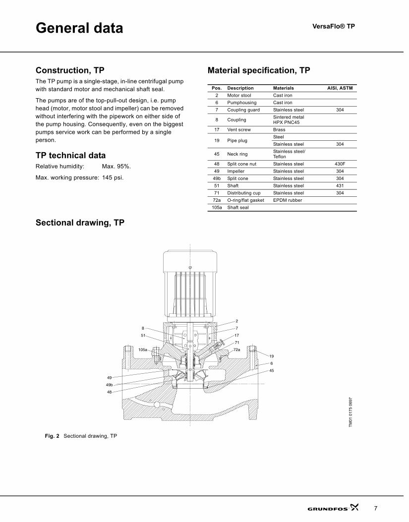
Construction, TPThe TP pump is a single-stage, in-line centrifugal pump with standard motor and mechanical shaft seal.
The pumps are of the top-pull-out design, i.e. pump head (motor, motor stool and impeller) can be removed without interfering with the pipework on either side of the pump housing. Consequently, even on the biggest pumps service work can be performed by a single person.
TP technical dataRelative humidity: Max. 95%.
Max. working pressure: 145 psi.
Material specification, TP
Sectional drawing, TP
Fig. 2 Sectional drawing, TP
Pos. Description Materials AISI, ASTM2 Motor stool Cast iron 6 Pumphousing Cast iron 7 Coupling guard Stainless steel 304
8 Coupling Sintered metalHPX PNC45
17 Vent screw Brass
19 Pipe plugSteelStainless steel 304
45 Neck ring Stainless steel/Teflon
48 Split cone nut Stainless steel 430F49 Impeller Stainless steel 30449b Split cone Stainless steel 30451 Shaft Stainless steel 43171 Distributing cup Stainless steel 30472a O-ring/flat gasket EPDM rubber105a Shaft seal
TM01
017
5 06
9772a
71
17
7
2
45
6
19
105a
51
8
49
49b
48
TPVersaFlo.book Page 7 Monday, August 20, 2007 3:55 PM
General data VersaFlo® TP
8
Motor The motor is a totally enclosed, fan-cooled standard motor with main dimensions to NEMA standards.
Mounting designation: NEMA C FACE
Enclosure class: TEFC; (ODP) optional
Insulation class: F
Ambient temperature: Max. 104°F.
PumpIn-line cast iron or bronze spiral pump housing.
Flange dimensions for USA are according to Industry and or ANSI Standard. The flanges have ¼ NPT pressure gauge tappings.
Tapped holes are provided on the underside of the pumps. These holes can be used for fitting the pump to a base plate, bracket or the like by means of hexagon screws. The pump housing is provided with a replaceable stainless steel/Teflon neck ring. The ring reduces to a minimum the amount of liquid running from the discharge side of the impeller to the suction side.
Surface treatmentThe pump housing and the motor stool are electrocoated .The treatment includes:
1. Alkaline cleaning.2. Pre-treatment with zinc phosphate coating.3. Cathodic electrocoating (epoxy).
Coating thickness: 15-20 μm.4. Curing of paint film at 200-250°C.
Motor stoolThe motor stool forms connection between the pump housing and the motor, and is equipped with a manual air vent screw for venting of the pump housing and the shaft seal chamber. The sealing between motor stool and pump housing is either an O-ring or a flat gasket.
The central part of the motor stool is provided with guards for protection against shaft and coupling.
The dimensions of the motor side flange of the motor stool are according to NEMA.
Pump shaftThe shaft is a cylindrical ∅16 mm stainless steel shaft. The coupling end of the shaft has a hole for the coupling shaft pin.
CouplingThe coupling is a two-piece, inelastic sintered metal coupling secured with four hexagon socket head screws.
ImpellerThe impeller is made of stainless steel, AISI 304 SS.
As the impeller is made of stainless steel sheet, it can be pressed into the correct hydraulic form.
Shaft sealThe pumps are fitted as standard with a single, unbalanced tungsten carbide/carbon rubber bellows shaft seal in a 16 mm diameter size with EPDM elastomer (BUBE). The tungsten carbide/carbon shaft seal has a wide range of applications and is especially suitable where there is a risk of dry running and in case of high temperatures.
The tungsten carbide/carbon shaft seal is not suitable for liquids containing abrasive particles, as the carbon parts will be worn down. In that case a tungsten carbide/ tungsten carbide seal is recommended.
Optional shaft seals available:• unbalanced tungsten carbide/tungsten carbide
O-ring shaft seal with EPDM elastomer (AUUE).
And for glycol/water mixtures:
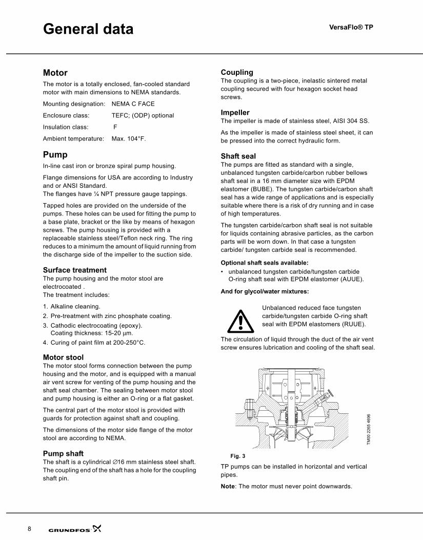
The circulation of liquid through the duct of the air vent screw ensures lubrication and cooling of the shaft seal.
Fig. 3
TP pumps can be installed in horizontal and vertical pipes.
Note: The motor must never point downwards.
Unbalanced reduced face tungstencarbide/tungsten carbide O-ring shaft seal with EPDM elastomers (RUUE).
TM00
226
5 46
96
TPVersaFlo.book Page 8 Monday, August 20, 2007 3:55 PM
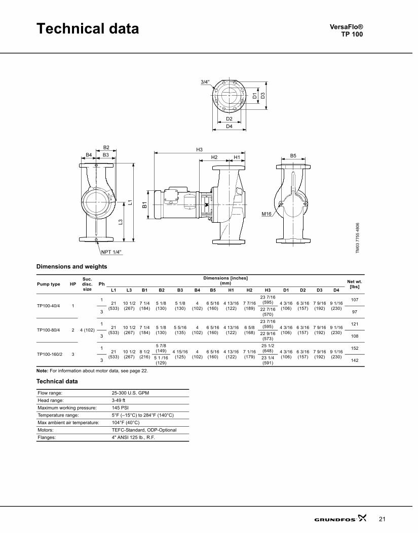
Technical data
21
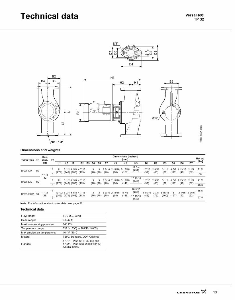
Dimensions and weights
Note: For information about motor data, see page 22.
Technical data
TM03
775
5 48
06
Pump type HPSuc.disc.size
PhDimensions [inches]
(mm) Net wt.[lbs]
L1 L3 B1 B2 B3 B4 B5 H1 H2 H3 D1 D2 D3 D4
TP100-40/4 1
4 (102)
121
(533)10 1/2(267)
7 1/4(184)
5 1/8(130)
5 1/8(130)
4(102)
6 5/16(160)
4 13/16(122)
7 7/16(189)
23 7/16(595) 4 3/16
(106)6 3/16(157)
7 9/16(192)
9 1/16(230)
107
3 22 7/16(570) 97
TP100-80/4 21
21(533)
10 1/2(267)
7 1/4(184)
5 1/8(130)
5 5/16(135)
4(102)
6 5/16(160)
4 13/16(122)
6 5/8(168)
23 7/16(595) 4 3/16
(106)6 3/16(157)
7 9/16(192)
9 1/16(230)
121
3 22 9/16(573) 108
TP100-160/2 31
21(533)
10 1/2(267)
8 1/2(216)
5 7/8(149) 4 15/16
(125)4
(102)6 5/16(160)
4 13/16(122)
7 1/16(179)
25 1/2(648) 4 3/16
(106)6 3/16(157)
7 9/16(192)
9 1/16(230)
152
3 5 1 /16(129)
23 1/4(591) 142
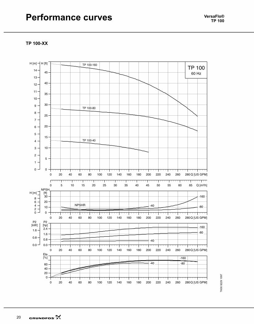
Flow range: 25-300 U.S. GPMHead range: 3-49 ftMaximum working pressure: 145 PSITemperature range: 5°F (–15°C) to 284°F (140°C)Max ambient air temperature: 104°F (40°C)Motors: TEFC-Standard, ODP-OptionalFlanges: 4" ANSI 125 lb., R.F.
VersaFlo®TP 100
TPVersaFlo.book Page 21 Monday, August 20, 2007 3:55 PM
Performance curves
20
TP 100-XX
TK00
922
9 10
97
VersaFlo®TP 100
TPVersaFlo.book Page 20 Monday, August 20, 2007 3:55 PM
General data VersaFlo® TP
9
The pumps must be installed in such a way that strain from the pipework is not transferred to the pump housing.
The pump may be suspended direct in the pipes, provided the pipework can support the pump. If not, the pump must be installed on a mounting bracket or base plate.
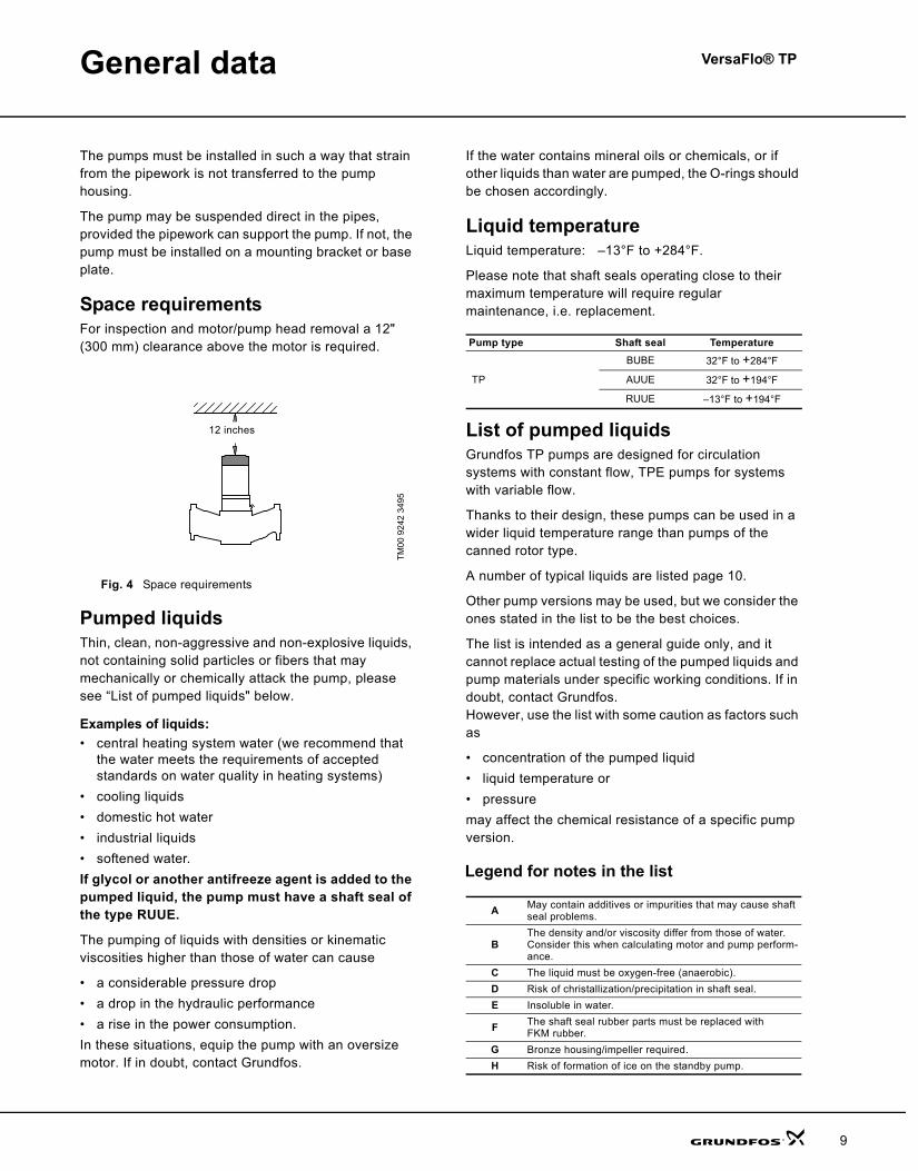
Space requirementsFor inspection and motor/pump head removal a 12" (300 mm) clearance above the motor is required.
Fig. 4 Space requirements
Pumped liquidsThin, clean, non-aggressive and non-explosive liquids, not containing solid particles or fibers that may mechanically or chemically attack the pump, please see “List of pumped liquids" below.
Examples of liquids:• central heating system water (we recommend that
the water meets the requirements of accepted standards on water quality in heating systems)
• cooling liquids• domestic hot water• industrial liquids• softened water.If glycol or another antifreeze agent is added to the pumped liquid, the pump must have a shaft seal of the type RUUE.
The pumping of liquids with densities or kinematic viscosities higher than those of water can cause
• a considerable pressure drop • a drop in the hydraulic performance • a rise in the power consumption.In these situations, equip the pump with an oversize motor. If in doubt, contact Grundfos.
If the water contains mineral oils or chemicals, or if other liquids than water are pumped, the O-rings should be chosen accordingly.
Liquid temperatureLiquid temperature: –13°F to +284°F.
Please note that shaft seals operating close to their maximum temperature will require regular maintenance, i.e. replacement.
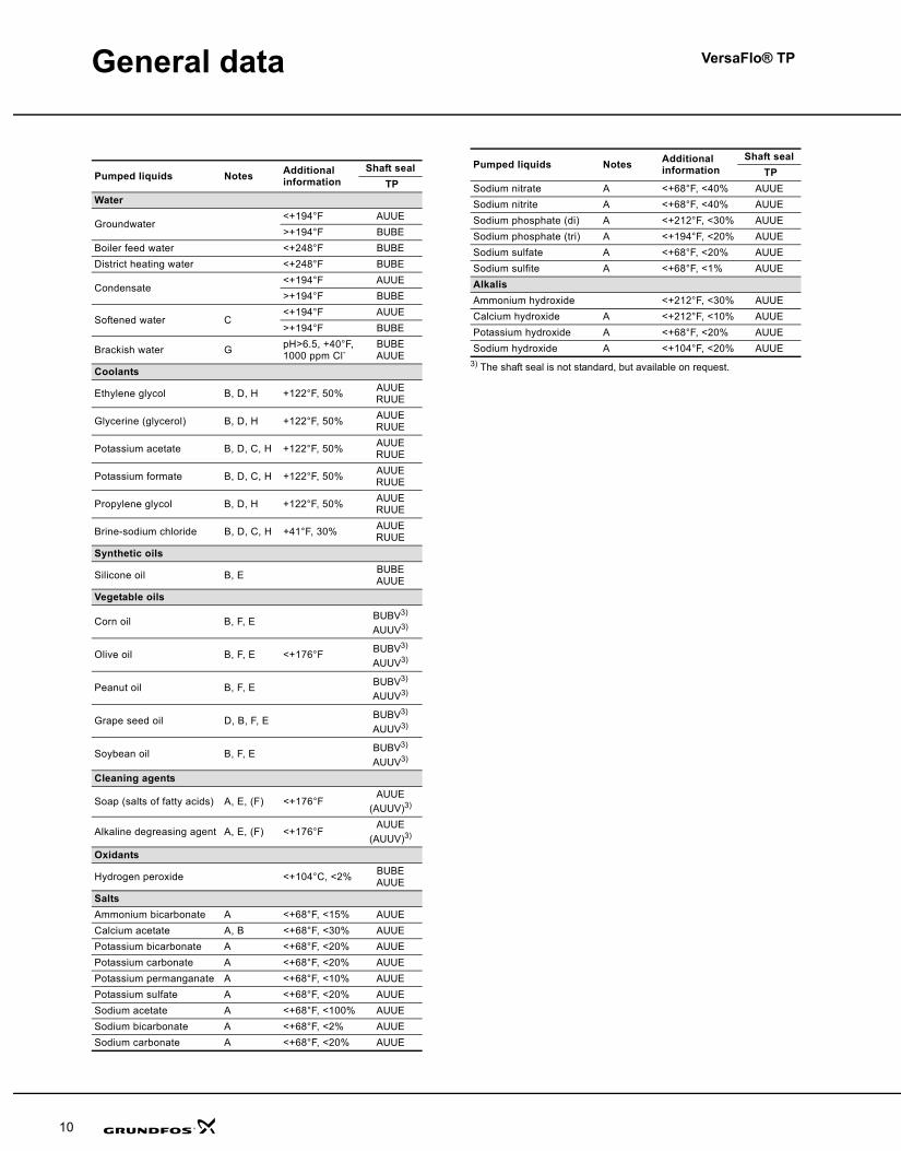
List of pumped liquidsGrundfos TP pumps are designed for circulation systems with constant flow, TPE pumps for systems with variable flow.
Thanks to their design, these pumps can be used in a wider liquid temperature range than pumps of the canned rotor type.
A number of typical liquids are listed page 10.
Other pump versions may be used, but we consider the ones stated in the list to be the best choices.
The list is intended as a general guide only, and it cannot replace actual testing of the pumped liquids and pump materials under specific working conditions. If in doubt, contact Grundfos. However, use the list with some caution as factors such as
• concentration of the pumped liquid• liquid temperature or• pressuremay affect the chemical resistance of a specific pump version.
Legend for notes in the list
TM00
924
2 34
95
300 mm12 inches
Pump type Shaft seal Temperature
TP
BUBE 32°F to +284°F
AUUE 32°F to +194°F
RUUE –13°F to +194°F
A May contain additives or impurities that may cause shaft seal problems.
BThe density and/or viscosity differ from those of water. Consider this when calculating motor and pump perform-ance.
C The liquid must be oxygen-free (anaerobic).D Risk of christallization/precipitation in shaft seal.E Insoluble in water.
F The shaft seal rubber parts must be replaced with FKM rubber.
G Bronze housing/impeller required.H Risk of formation of ice on the standby pump.
TPVersaFlo.book Page 9 Monday, August 20, 2007 3:55 PM
General data VersaFlo® TP
10
3) The shaft seal is not standard, but available on request.
Pumped liquids Notes Additional information
Shaft seal TP
Water
Groundwater<+194°F AUUE>+194°F BUBE
Boiler feed water <+248°F BUBEDistrict heating water <+248°F BUBE
Condensate<+194°F AUUE>+194°F BUBE
Softened water C<+194°F AUUE>+194°F BUBE
Brackish water G pH>6.5, +40°F,1000 ppm Cl-
BUBEAUUE
Coolants
Ethylene glycol B, D, H +122°F, 50% AUUERUUE
Glycerine (glycerol) B, D, H +122°F, 50% AUUERUUE
Potassium acetate B, D, C, H +122°F, 50% AUUERUUE
Potassium formate B, D, C, H +122°F, 50% AUUERUUE
Propylene glycol B, D, H +122°F, 50% AUUERUUE
Brine-sodium chloride B, D, C, H +41°F, 30% AUUERUUE
Synthetic oils
Silicone oil B, E BUBEAUUE
Vegetable oils
Corn oil B, F, E BUBV3) AUUV3)
Olive oil B, F, E <+176°F BUBV3) AUUV3)
Peanut oil B, F, E BUBV3) AUUV3)
Grape seed oil D, B, F, E BUBV3) AUUV3)
Soybean oil B, F, E BUBV3) AUUV3)
Cleaning agents
Soap (salts of fatty acids) A, E, (F) <+176°FAUUE
(AUUV)3)
Alkaline degreasing agent A, E, (F) <+176°FAUUE
(AUUV)3) Oxidants
Hydrogen peroxide <+104°C, <2% BUBEAUUE
SaltsAmmonium bicarbonate A <+68°F, <15% AUUECalcium acetate A, B <+68°F, <30% AUUEPotassium bicarbonate A <+68°F, <20% AUUEPotassium carbonate A <+68°F, <20% AUUEPotassium permanganate A <+68°F, <10% AUUEPotassium sulfate A <+68°F, <20% AUUESodium acetate A <+68°F, <100% AUUESodium bicarbonate A <+68°F, <2% AUUESodium carbonate A <+68°F, <20% AUUE
Sodium nitrate A <+68°F, <40% AUUESodium nitrite A <+68°F, <40% AUUESodium phosphate (di) A <+212°F, <30% AUUESodium phosphate (tri) A <+194°F, <20% AUUESodium sulfate A <+68°F, <20% AUUESodium sulfite A <+68°F, <1% AUUEAlkalisAmmonium hydroxide <+212°F, <30% AUUECalcium hydroxide A <+212°F, <10% AUUEPotassium hydroxide A <+68°F, <20% AUUESodium hydroxide A <+104°F, <20% AUUE
Pumped liquids Notes Additional information
Shaft seal TP
TPVersaFlo.book Page 10 Monday, August 20, 2007 3:55 PM
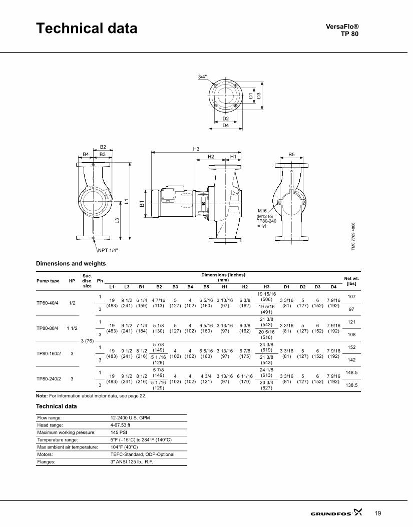
Technical data
19
Dimensions and weights
Note: For information about motor data, see page 22.
Technical data
TM0
7769
480
6
Pump type HPSuc. disc.size
PhDimensions [inches]
(mm) Net wt.[lbs]
L1 L3 B1 B2 B3 B4 B5 H1 H2 H3 D1 D2 D3 D4
TP80-40/4 1/2
3 (76)
119
(483)9 1/2(241)
6 1/4(159)
4 7/16(113)
5(127)
4(102)
6 5/16(160)
3 13/16(97)
6 3/8(162)
19 15/16(506) 3 3/16
(81)5
(127)6
(152)7 9/16(192)
107
3 19 5/16(491) 97
TP80-80/4 1 1/21
19(483)
9 1/2(241)
7 1/4(184)
5 1/8(130)
5(127)
4(102)
6 5/16(160)
3 13/16(97)
6 3/8(162)
21 3/8(543) 3 3/16
(81)5
(127)6
(152)7 9/16(192)
121
3 20 5/16(516) 108
TP80-160/2 31
19(483)
9 1/2(241)
8 1/2(216)
5 7/8(149) 4
(102)4
(102)6 5/16(160)
3 13/16(97)
6 7/8(175)
24 3/8(619) 3 3/16
(81)5
(127)6
(152)7 9/16(192)
152
3 5 1 /16(129)
21 3/8(543) 142
TP80-240/2 31
19(483)
9 1/2(241)
8 1/2(216)
5 7/8(149) 4
(102)4
(102)4 3/4(121)
3 13/16(97)
6 11/16(170)
24 1/8(613) 3 3/16
(81)5
(127)6
(152)7 9/16(192)
148.5
3 5 1 /16(129)
20 3/4(527) 138.5
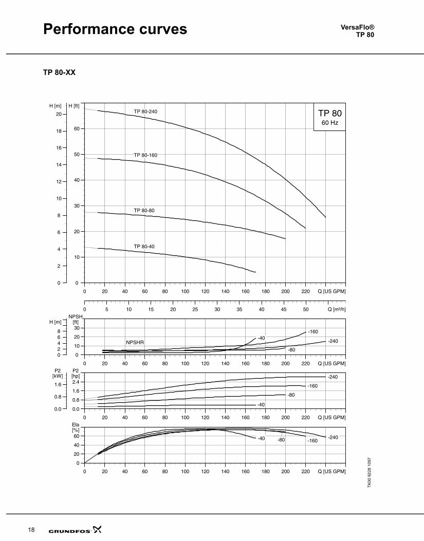
Flow range: 12-2400 U.S. GPMHead range: 4-67.53 ftMaximum working pressure: 145 PSITemperature range: 5°F (–15°C) to 284°F (140°C)Max ambient air temperature: 104°F (40°C)Motors: TEFC-Standard, ODP-OptionalFlanges: 3" ANSI 125 lb., R.F.
VersaFlo®TP 80
TPVersaFlo.book Page 19 Monday, August 20, 2007 3:55 PM

Performance curves
18
TP 80-XX
TK00
922
8 10
97
VersaFlo®TP 80
TPVersaFlo.book Page 18 Monday, August 20, 2007 3:55 PM
11
TPVersaFlo.book Page 11 Monday, August 20, 2007 3:55 PM
12
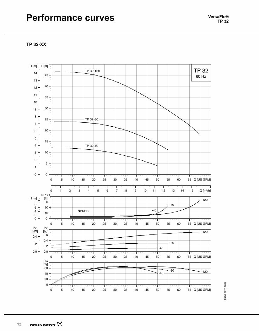
Performance curves
TP 32-XX
TK00
922
5 18
97
VersaFlo®TP 32
TPVersaFlo.book Page 12 Monday, August 20, 2007 3:55 PM
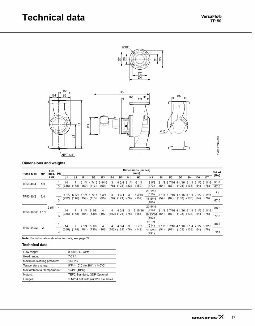
Technical data
17
Dimensions and weights
Note: For information about motor data, see page 22.
Technical data
TM03
775
6 48
06
Pump type HPSuc. disc. size
PhDimensions [inches]
(mm) Net wt.[lbs]
L1 L3 B1 B2 B3 B4 B5 H1 H2 H3 D1 D2 D3 D4 D6 D7
TP50-40/4 1/3
2 (51)
1 14(356)
7(178)
6 1/4(159)
4 7/16(113)
3 9/16(90)
3(76)
4 3/4(121)
3 1/4(83)
6 1/4(159)
18 5/8(473)
2 1/8(54)
3 7/16(87)
4 1/16(103)
5 1/4(133)
2 1/2(64)
3 1/16(78)
61.53 67.5
TP50-80/2 3/41
11 1/2(292)
5 3/4(146)
6 1/4(159)
4 7/16(113)
3 3/4(95)
3(76)
4 3/4(121)
3(76)
6 3/16(157)
20 1/16(510) 2 1/8
(54)3 7/16(87)
4 1/16(103)
5 1/4(133)
2 1/2(64)
3 1/16(78)
71
3 18 5/16(465) 67.5
TP50-160/2 1 1/21
14(356)
7(178)
7 1/4(184)
5 1/8(130)
4(102)
4(102)
4 3/4(121)
3(76)
5 15/16(151)
20 5/16(516) 2 1/8
(54)3 7/16(87)
4 1/16(103)
5 1/4(133)
2 1/2(64)
3 1/16(78)
86.5
3 19 13/16(503) 77.5
TP50-240/2 21
14(356)
7(178)
7 1/4(184)
5 1/8(130)
4(102)
4(102)
4 3/4(121)
3(76)
5 7/8(149)
20 1/4(514) 2 1/8
(54)3 7/16(87)
4 1/16(103)
5 1/4(133)
2 1/2(64)
3 1/16(78)
88.5
3 19 5/16(491) 79.5
Flow range: 8-150 U.S. GPMHead range: 7-63 ftMaximum working pressure: 145 PSITemperature range: 5°F (–15°C) to 284°* (140°C)Max ambient air temperature: 104°F (40°C)Motors: TEFC-Standard, ODP-OptionalFlanges: 1 1/2" 4 bolt with (4) 9/16 dia. holes
VersaFlo®TP 50
TPVersaFlo.book Page 17 Monday, August 20, 2007 3:55 PM
Performance curves
16
TP 50-XX
TK00
922
7 18
97
VersaFlo®TP 50
TPVersaFlo.book Page 16 Monday, August 20, 2007 3:55 PM
Technical data
13
Dimensions and weights
Note: For information about motor data, see page 22.
Technical data
TM03
775
7 48
06
Pump type HPSuc.disc.size
PhDimensions [inches]
(mm) Net wt.[lbs]
L1 L3 B1 B2 B3 B4 B5 B7 H1 H2 H3 D1 D2 D3 D4 D6 D7
TP32-40/4 1/31 1/4 (32)
1 11(279)
5 1/2(140)
6 5/8(168)
4 7/16(113)
3(76)
3(76)
3 3/16(78)
2 11/16(68)
5 15/16(151)
17 3/4(451) 1 7/16
(37)2 9/16(65)
3 1/2(89)
4 5/8(117)
1 13/16(46)
2 1/4(57)
51.5
3 50
TP32-80/2 1/21 11
(279)5 1/2(140)
6 5/8(168)
4 7/16(113)
3(76)
3(76)
3 3/16(78)
2 11/16(68)
5 13/16(148)
17 11/16(449) 1 7/16
(37)2 9/16(65)
3 1/2(89)
4 5/8(117)
1 13/16(46)
2 1/4(57)
51.5
3 48.5
TP32-160/2 3/4 1 1/2 (38)
113 1/2(343)
6 3/4(171)
6 5/8(168)
4 7/16(113)
3(76)
3(76)
3 3/16(78)
2 11/16(68)
5 7/8(149)
18 3/16(462) 1 11/16
(43)2 7/8(73)
3 15/16(100)
5(127)
2 1/16(52)
2 9/16(52)
55.5
3 17 11/16(449) 57.5
Flow range: 8-70 U.S. GPMHead range: 3.5-47 ftMaximum working pressure: 145 PSITemperature range: 5°F (–15°C) to 284°F (140°C)Max ambient air temperature: 104°F (40°C)Motors: TEFC-Standard, ODP-Optional
Flanges:1 1/4" (TP32-40, TP32-80) and 1 1/2" (TP32-160), 2 bolt with (2)5/8 dia. holes
VersaFlo®TP 32
TPVersaFlo.book Page 13 Monday, August 20, 2007 3:55 PM
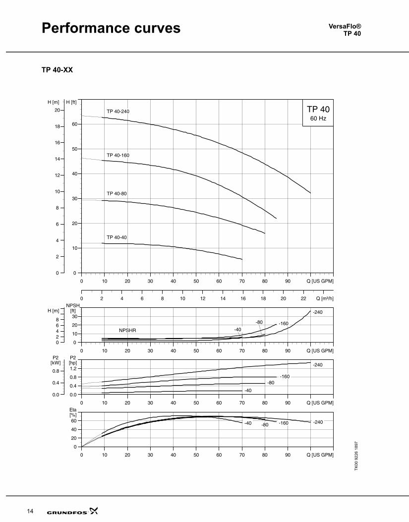
Performance curves
14
TP 40-XX
TK00
922
6 18
97
VersaFlo®TP 40
TPVersaFlo.book Page 14 Monday, August 20, 2007 3:55 PM
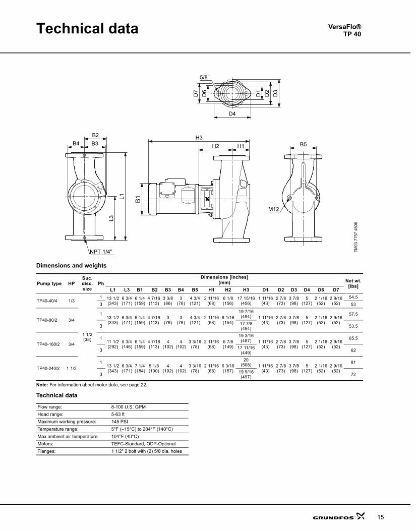
Technical data
15
Dimensions and weights
Note: For information about motor data, see page 22.
Technical data
TM03
775
7 48
06
Pump type HPSuc. disc.size
PhDimensions [inches]
(mm) Net wt.[lbs]
L1 L3 B1 B2 B3 B4 B5 H1 H2 H3 D1 D2 D3 D4 D6 D7
TP40-40/4 1/3
1 1/2 (38)
1 13 1/2(343)
6 3/4(171)
6 1/4(159)
4 7/16(113)
3 3/8(86)
3(76)
4 3/4(121)
2 11/16(68)
6 1/8(156)
17 15/16(456)
1 11/16(43)
2 7/8(73)
3 7/8(98)
5(127)
2 1/16(52)
2 9/16(52)
54.5
3 53
TP40-80/2 3/41
13 1/2(343)
6 3/4(171)
6 1/4(159)
4 7/16(113)
3(76)
3(76)
4 3/4(121)
2 11/16(68)
6 1/16(154)
19 7/16(494) 1 11/16
(43)2 7/8(73)
3 7/8(98)
5(127)
2 1/16(52)
2 9/16(52)
57.5
3 17 7/8(454) 53.5
TP40-160/2 3/41
11 1/2(292)
5 3/4(146)
6 1/4(159)
4 7/16(113)
4(102)
4(102)
3 3/16(78)
2 11/16(68)
5 7/8(149)
19 3/16(487) 1 11/16
(43)2 7/8(73)
3 7/8(98)
5(127)
2 1/16(52)
2 9/16(52)
65.5
3 17 11/16(449) 62
TP40-240/2 1 1/21
13 1/2(343)
6 3/4(171)
7 1/4(184)
5 1/8(130)
4(102)
4(102)
3 3/16(78)
2 11/16(68)
6 3/16(157)
20(508) 1 11/16
(43)2 7/8(73)
3 7/8(98)
5(127)
2 1/16(52)
2 9/16(52)
81
3 19 9/16(497) 72
Flow range: 8-100 U.S. GPMHead range: 5-63 ftMaximum working pressure: 145 PSITemperature range: 5°F (–15°C) to 284°F (140°C)Max ambient air temperature: 104°F (40°C)Motors: TEFC-Standard, ODP-OptionalFlanges: 1 1/2" 2 bolt with (2) 5/8 dia. holes
VersaFlo®TP 40
TPVersaFlo.book Page 15 Monday, August 20, 2007 3:55 PM
Performance curves
14
TP 40-XX
TK00
922
6 18
97
VersaFlo®TP 40
TPVersaFlo.book Page 14 Monday, August 20, 2007 3:55 PM
Technical data
15
Dimensions and weights
Note: For information about motor data, see page 22.
Technical data
TM03
775
7 48
06
Pump type HPSuc. disc.size
PhDimensions [inches]
(mm) Net wt.[lbs]
L1 L3 B1 B2 B3 B4 B5 H1 H2 H3 D1 D2 D3 D4 D6 D7
TP40-40/4 1/3
1 1/2 (38)
1 13 1/2(343)
6 3/4(171)
6 1/4(159)
4 7/16(113)
3 3/8(86)
3(76)
4 3/4(121)
2 11/16(68)
6 1/8(156)
17 15/16(456)
1 11/16(43)
2 7/8(73)
3 7/8(98)
5(127)
2 1/16(52)
2 9/16(52)
54.5
3 53
TP40-80/2 3/41
13 1/2(343)
6 3/4(171)
6 1/4(159)
4 7/16(113)
3(76)
3(76)
4 3/4(121)
2 11/16(68)
6 1/16(154)
19 7/16(494) 1 11/16
(43)2 7/8(73)
3 7/8(98)
5(127)
2 1/16(52)
2 9/16(52)
57.5
3 17 7/8(454) 53.5
TP40-160/2 3/41
11 1/2(292)
5 3/4(146)
6 1/4(159)
4 7/16(113)
4(102)
4(102)
3 3/16(78)
2 11/16(68)
5 7/8(149)
19 3/16(487) 1 11/16
(43)2 7/8(73)
3 7/8(98)
5(127)
2 1/16(52)
2 9/16(52)
65.5
3 17 11/16(449) 62
TP40-240/2 1 1/21
13 1/2(343)
6 3/4(171)
7 1/4(184)
5 1/8(130)
4(102)
4(102)
3 3/16(78)
2 11/16(68)
6 3/16(157)
20(508) 1 11/16
(43)2 7/8(73)
3 7/8(98)
5(127)
2 1/16(52)
2 9/16(52)
81
3 19 9/16(497) 72
Flow range: 8-100 U.S. GPMHead range: 5-63 ftMaximum working pressure: 145 PSITemperature range: 5°F (–15°C) to 284°F (140°C)Max ambient air temperature: 104°F (40°C)Motors: TEFC-Standard, ODP-OptionalFlanges: 1 1/2" 2 bolt with (2) 5/8 dia. holes
VersaFlo®TP 40
TPVersaFlo.book Page 15 Monday, August 20, 2007 3:55 PM
Performance curves
16
TP 50-XX
TK00
922
7 18
97
VersaFlo®TP 50
TPVersaFlo.book Page 16 Monday, August 20, 2007 3:55 PM
Technical data
13
Dimensions and weights
Note: For information about motor data, see page 22.
Technical data
TM03
775
7 48
06
Pump type HPSuc.disc.size
PhDimensions [inches]
(mm) Net wt.[lbs]
L1 L3 B1 B2 B3 B4 B5 B7 H1 H2 H3 D1 D2 D3 D4 D6 D7
TP32-40/4 1/31 1/4 (32)
1 11(279)
5 1/2(140)
6 5/8(168)
4 7/16(113)
3(76)
3(76)
3 3/16(78)
2 11/16(68)
5 15/16(151)
17 3/4(451) 1 7/16
(37)2 9/16(65)
3 1/2(89)
4 5/8(117)
1 13/16(46)
2 1/4(57)
51.5
3 50
TP32-80/2 1/21 11
(279)5 1/2(140)
6 5/8(168)
4 7/16(113)
3(76)
3(76)
3 3/16(78)
2 11/16(68)
5 13/16(148)
17 11/16(449) 1 7/16
(37)2 9/16(65)
3 1/2(89)
4 5/8(117)
1 13/16(46)
2 1/4(57)
51.5
3 48.5
TP32-160/2 3/4 1 1/2 (38)
113 1/2(343)
6 3/4(171)
6 5/8(168)
4 7/16(113)
3(76)
3(76)
3 3/16(78)
2 11/16(68)
5 7/8(149)
18 3/16(462) 1 11/16
(43)2 7/8(73)
3 15/16(100)
5(127)
2 1/16(52)
2 9/16(52)
55.5
3 17 11/16(449) 57.5
Flow range: 8-70 U.S. GPMHead range: 3.5-47 ftMaximum working pressure: 145 PSITemperature range: 5°F (–15°C) to 284°F (140°C)Max ambient air temperature: 104°F (40°C)Motors: TEFC-Standard, ODP-Optional
Flanges:1 1/4" (TP32-40, TP32-80) and 1 1/2" (TP32-160), 2 bolt with (2)5/8 dia. holes
VersaFlo®TP 32
TPVersaFlo.book Page 13 Monday, August 20, 2007 3:55 PM
12
Performance curves
TP 32-XX
TK00
922
5 18
97
VersaFlo®TP 32
TPVersaFlo.book Page 12 Monday, August 20, 2007 3:55 PM
Technical data
17
Dimensions and weights
Note: For information about motor data, see page 22.
Technical data
TM03
775
6 48
06
Pump type HPSuc. disc. size
PhDimensions [inches]
(mm) Net wt.[lbs]
L1 L3 B1 B2 B3 B4 B5 H1 H2 H3 D1 D2 D3 D4 D6 D7
TP50-40/4 1/3
2 (51)
1 14(356)
7(178)
6 1/4(159)
4 7/16(113)
3 9/16(90)
3(76)
4 3/4(121)
3 1/4(83)
6 1/4(159)
18 5/8(473)
2 1/8(54)
3 7/16(87)
4 1/16(103)
5 1/4(133)
2 1/2(64)
3 1/16(78)
61.53 67.5
TP50-80/2 3/41
11 1/2(292)
5 3/4(146)
6 1/4(159)
4 7/16(113)
3 3/4(95)
3(76)
4 3/4(121)
3(76)
6 3/16(157)
20 1/16(510) 2 1/8
(54)3 7/16(87)
4 1/16(103)
5 1/4(133)
2 1/2(64)
3 1/16(78)
71
3 18 5/16(465) 67.5
TP50-160/2 1 1/21
14(356)
7(178)
7 1/4(184)
5 1/8(130)
4(102)
4(102)
4 3/4(121)
3(76)
5 15/16(151)
20 5/16(516) 2 1/8
(54)3 7/16(87)
4 1/16(103)
5 1/4(133)
2 1/2(64)
3 1/16(78)
86.5
3 19 13/16(503) 77.5
TP50-240/2 21
14(356)
7(178)
7 1/4(184)
5 1/8(130)
4(102)
4(102)
4 3/4(121)
3(76)
5 7/8(149)
20 1/4(514) 2 1/8
(54)3 7/16(87)
4 1/16(103)
5 1/4(133)
2 1/2(64)
3 1/16(78)
88.5
3 19 5/16(491) 79.5
Flow range: 8-150 U.S. GPMHead range: 7-63 ftMaximum working pressure: 145 PSITemperature range: 5°F (–15°C) to 284°* (140°C)Max ambient air temperature: 104°F (40°C)Motors: TEFC-Standard, ODP-OptionalFlanges: 1 1/2" 4 bolt with (4) 9/16 dia. holes
VersaFlo®TP 50
TPVersaFlo.book Page 17 Monday, August 20, 2007 3:55 PM
Performance curves
18
TP 80-XX
TK00
922
8 10
97
VersaFlo®TP 80
TPVersaFlo.book Page 18 Monday, August 20, 2007 3:55 PM
11
TPVersaFlo.book Page 11 Monday, August 20, 2007 3:55 PM
General data VersaFlo® TP
10
3) The shaft seal is not standard, but available on request.
Pumped liquids Notes Additional information
Shaft seal TP
Water
Groundwater<+194°F AUUE>+194°F BUBE
Boiler feed water <+248°F BUBEDistrict heating water <+248°F BUBE
Condensate<+194°F AUUE>+194°F BUBE
Softened water C<+194°F AUUE>+194°F BUBE
Brackish water G pH>6.5, +40°F,1000 ppm Cl-
BUBEAUUE
Coolants
Ethylene glycol B, D, H +122°F, 50% AUUERUUE
Glycerine (glycerol) B, D, H +122°F, 50% AUUERUUE
Potassium acetate B, D, C, H +122°F, 50% AUUERUUE
Potassium formate B, D, C, H +122°F, 50% AUUERUUE
Propylene glycol B, D, H +122°F, 50% AUUERUUE
Brine-sodium chloride B, D, C, H +41°F, 30% AUUERUUE
Synthetic oils
Silicone oil B, E BUBEAUUE
Vegetable oils
Corn oil B, F, E BUBV3) AUUV3)
Olive oil B, F, E <+176°F BUBV3) AUUV3)
Peanut oil B, F, E BUBV3) AUUV3)
Grape seed oil D, B, F, E BUBV3) AUUV3)
Soybean oil B, F, E BUBV3) AUUV3)
Cleaning agents
Soap (salts of fatty acids) A, E, (F) <+176°FAUUE
(AUUV)3)
Alkaline degreasing agent A, E, (F) <+176°FAUUE
(AUUV)3) Oxidants
Hydrogen peroxide <+104°C, <2% BUBEAUUE
SaltsAmmonium bicarbonate A <+68°F, <15% AUUECalcium acetate A, B <+68°F, <30% AUUEPotassium bicarbonate A <+68°F, <20% AUUEPotassium carbonate A <+68°F, <20% AUUEPotassium permanganate A <+68°F, <10% AUUEPotassium sulfate A <+68°F, <20% AUUESodium acetate A <+68°F, <100% AUUESodium bicarbonate A <+68°F, <2% AUUESodium carbonate A <+68°F, <20% AUUE
Sodium nitrate A <+68°F, <40% AUUESodium nitrite A <+68°F, <40% AUUESodium phosphate (di) A <+212°F, <30% AUUESodium phosphate (tri) A <+194°F, <20% AUUESodium sulfate A <+68°F, <20% AUUESodium sulfite A <+68°F, <1% AUUEAlkalisAmmonium hydroxide <+212°F, <30% AUUECalcium hydroxide A <+212°F, <10% AUUEPotassium hydroxide A <+68°F, <20% AUUESodium hydroxide A <+104°F, <20% AUUE
Pumped liquids Notes Additional information
Shaft seal TP
TPVersaFlo.book Page 10 Monday, August 20, 2007 3:55 PM
Technical data
19
Dimensions and weights
Note: For information about motor data, see page 22.
Technical data
TM0
7769
480
6
Pump type HPSuc. disc.size
PhDimensions [inches]
(mm) Net wt.[lbs]
L1 L3 B1 B2 B3 B4 B5 H1 H2 H3 D1 D2 D3 D4
TP80-40/4 1/2
3 (76)
119
(483)9 1/2(241)
6 1/4(159)
4 7/16(113)
5(127)
4(102)
6 5/16(160)
3 13/16(97)
6 3/8(162)
19 15/16(506) 3 3/16
(81)5
(127)6
(152)7 9/16(192)
107
3 19 5/16(491) 97
TP80-80/4 1 1/21
19(483)
9 1/2(241)
7 1/4(184)
5 1/8(130)
5(127)
4(102)
6 5/16(160)
3 13/16(97)
6 3/8(162)
21 3/8(543) 3 3/16
(81)5
(127)6
(152)7 9/16(192)
121
3 20 5/16(516) 108
TP80-160/2 31
19(483)
9 1/2(241)
8 1/2(216)
5 7/8(149) 4
(102)4
(102)6 5/16(160)
3 13/16(97)
6 7/8(175)
24 3/8(619) 3 3/16
(81)5
(127)6
(152)7 9/16(192)
152
3 5 1 /16(129)
21 3/8(543) 142
TP80-240/2 31
19(483)
9 1/2(241)
8 1/2(216)
5 7/8(149) 4
(102)4
(102)4 3/4(121)
3 13/16(97)
6 11/16(170)
24 1/8(613) 3 3/16
(81)5
(127)6
(152)7 9/16(192)
148.5
3 5 1 /16(129)
20 3/4(527) 138.5
Flow range: 12-2400 U.S. GPMHead range: 4-67.53 ftMaximum working pressure: 145 PSITemperature range: 5°F (–15°C) to 284°F (140°C)Max ambient air temperature: 104°F (40°C)Motors: TEFC-Standard, ODP-OptionalFlanges: 3" ANSI 125 lb., R.F.
VersaFlo®TP 80
TPVersaFlo.book Page 19 Monday, August 20, 2007 3:55 PM
Performance curves
20
TP 100-XX
TK00
922
9 10
97
VersaFlo®TP 100
TPVersaFlo.book Page 20 Monday, August 20, 2007 3:55 PM
General data VersaFlo® TP
9
The pumps must be installed in such a way that strain from the pipework is not transferred to the pump housing.
The pump may be suspended direct in the pipes, provided the pipework can support the pump. If not, the pump must be installed on a mounting bracket or base plate.
Space requirementsFor inspection and motor/pump head removal a 12" (300 mm) clearance above the motor is required.
Fig. 4 Space requirements
Pumped liquidsThin, clean, non-aggressive and non-explosive liquids, not containing solid particles or fibers that may mechanically or chemically attack the pump, please see “List of pumped liquids" below.
Examples of liquids:• central heating system water (we recommend that
the water meets the requirements of accepted standards on water quality in heating systems)
• cooling liquids• domestic hot water• industrial liquids• softened water.If glycol or another antifreeze agent is added to the pumped liquid, the pump must have a shaft seal of the type RUUE.
The pumping of liquids with densities or kinematic viscosities higher than those of water can cause
• a considerable pressure drop • a drop in the hydraulic performance • a rise in the power consumption.In these situations, equip the pump with an oversize motor. If in doubt, contact Grundfos.
If the water contains mineral oils or chemicals, or if other liquids than water are pumped, the O-rings should be chosen accordingly.
Liquid temperatureLiquid temperature: –13°F to +284°F.
Please note that shaft seals operating close to their maximum temperature will require regular maintenance, i.e. replacement.
List of pumped liquidsGrundfos TP pumps are designed for circulation systems with constant flow, TPE pumps for systems with variable flow.
Thanks to their design, these pumps can be used in a wider liquid temperature range than pumps of the canned rotor type.
A number of typical liquids are listed page 10.
Other pump versions may be used, but we consider the ones stated in the list to be the best choices.
The list is intended as a general guide only, and it cannot replace actual testing of the pumped liquids and pump materials under specific working conditions. If in doubt, contact Grundfos. However, use the list with some caution as factors such as
• concentration of the pumped liquid• liquid temperature or• pressuremay affect the chemical resistance of a specific pump version.
Legend for notes in the list
TM00
924
2 34
95
300 mm12 inches
Pump type Shaft seal Temperature
TP
BUBE 32°F to +284°F
AUUE 32°F to +194°F
RUUE –13°F to +194°F
A May contain additives or impurities that may cause shaft seal problems.
BThe density and/or viscosity differ from those of water. Consider this when calculating motor and pump perform-ance.
C The liquid must be oxygen-free (anaerobic).D Risk of christallization/precipitation in shaft seal.E Insoluble in water.
F The shaft seal rubber parts must be replaced with FKM rubber.
G Bronze housing/impeller required.H Risk of formation of ice on the standby pump.
TPVersaFlo.book Page 9 Monday, August 20, 2007 3:55 PM
General data VersaFlo® TP
8
Motor The motor is a totally enclosed, fan-cooled standard motor with main dimensions to NEMA standards.
Mounting designation: NEMA C FACE
Enclosure class: TEFC; (ODP) optional
Insulation class: F
Ambient temperature: Max. 104°F.
PumpIn-line cast iron or bronze spiral pump housing.
Flange dimensions for USA are according to Industry and or ANSI Standard. The flanges have ¼ NPT pressure gauge tappings.
Tapped holes are provided on the underside of the pumps. These holes can be used for fitting the pump to a base plate, bracket or the like by means of hexagon screws. The pump housing is provided with a replaceable stainless steel/Teflon neck ring. The ring reduces to a minimum the amount of liquid running from the discharge side of the impeller to the suction side.
Surface treatmentThe pump housing and the motor stool are electrocoated .The treatment includes:
1. Alkaline cleaning.2. Pre-treatment with zinc phosphate coating.3. Cathodic electrocoating (epoxy).
Coating thickness: 15-20 μm.4. Curing of paint film at 200-250°C.
Motor stoolThe motor stool forms connection between the pump housing and the motor, and is equipped with a manual air vent screw for venting of the pump housing and the shaft seal chamber. The sealing between motor stool and pump housing is either an O-ring or a flat gasket.
The central part of the motor stool is provided with guards for protection against shaft and coupling.
The dimensions of the motor side flange of the motor stool are according to NEMA.
Pump shaftThe shaft is a cylindrical ∅16 mm stainless steel shaft. The coupling end of the shaft has a hole for the coupling shaft pin.
CouplingThe coupling is a two-piece, inelastic sintered metal coupling secured with four hexagon socket head screws.
ImpellerThe impeller is made of stainless steel, AISI 304 SS.
As the impeller is made of stainless steel sheet, it can be pressed into the correct hydraulic form.
Shaft sealThe pumps are fitted as standard with a single, unbalanced tungsten carbide/carbon rubber bellows shaft seal in a 16 mm diameter size with EPDM elastomer (BUBE). The tungsten carbide/carbon shaft seal has a wide range of applications and is especially suitable where there is a risk of dry running and in case of high temperatures.
The tungsten carbide/carbon shaft seal is not suitable for liquids containing abrasive particles, as the carbon parts will be worn down. In that case a tungsten carbide/ tungsten carbide seal is recommended.
Optional shaft seals available:• unbalanced tungsten carbide/tungsten carbide
O-ring shaft seal with EPDM elastomer (AUUE).
And for glycol/water mixtures:
The circulation of liquid through the duct of the air vent screw ensures lubrication and cooling of the shaft seal.
Fig. 3
TP pumps can be installed in horizontal and vertical pipes.
Note: The motor must never point downwards.
Unbalanced reduced face tungstencarbide/tungsten carbide O-ring shaft seal with EPDM elastomers (RUUE).
TM00
226
5 46
96
TPVersaFlo.book Page 8 Monday, August 20, 2007 3:55 PM
Technical data
21
Dimensions and weights
Note: For information about motor data, see page 22.
Technical data
TM03
775
5 48
06
Pump type HPSuc.disc.size
PhDimensions [inches]
(mm) Net wt.[lbs]
L1 L3 B1 B2 B3 B4 B5 H1 H2 H3 D1 D2 D3 D4
TP100-40/4 1
4 (102)
121
(533)10 1/2(267)
7 1/4(184)
5 1/8(130)
5 1/8(130)
4(102)
6 5/16(160)
4 13/16(122)
7 7/16(189)
23 7/16(595) 4 3/16
(106)6 3/16(157)
7 9/16(192)
9 1/16(230)
107
3 22 7/16(570) 97
TP100-80/4 21
21(533)
10 1/2(267)
7 1/4(184)
5 1/8(130)
5 5/16(135)
4(102)
6 5/16(160)
4 13/16(122)
6 5/8(168)
23 7/16(595) 4 3/16
(106)6 3/16(157)
7 9/16(192)
9 1/16(230)
121
3 22 9/16(573) 108
TP100-160/2 31
21(533)
10 1/2(267)
8 1/2(216)
5 7/8(149) 4 15/16
(125)4
(102)6 5/16(160)
4 13/16(122)
7 1/16(179)
25 1/2(648) 4 3/16
(106)6 3/16(157)
7 9/16(192)
9 1/16(230)
152
3 5 1 /16(129)
23 1/4(591) 142
Flow range: 25-300 U.S. GPMHead range: 3-49 ftMaximum working pressure: 145 PSITemperature range: 5°F (–15°C) to 284°F (140°C)Max ambient air temperature: 104°F (40°C)Motors: TEFC-Standard, ODP-OptionalFlanges: 4" ANSI 125 lb., R.F.
VersaFlo®TP 100
TPVersaFlo.book Page 21 Monday, August 20, 2007 3:55 PM
VersaFlo® TP
22
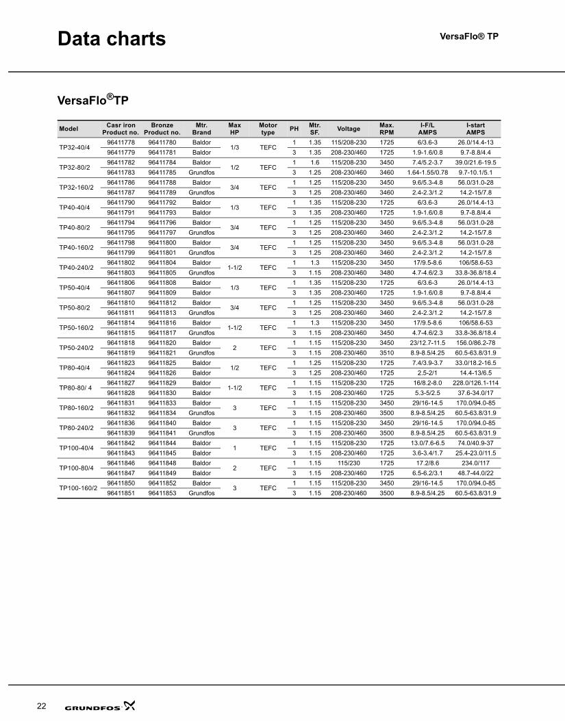
Data charts
VersaFlo®TP
Model Casr ironProduct no.
BronzeProduct no.
Mtr.Brand
Max HP
Motor type PH Mtr.
SF. Voltage Max.RPM
I-F/L AMPS
I-start AMPS
TP32-40/496411778 96411780 Baldor
1/3 TEFC1 1.35 115/208-230 1725 6/3.6-3 26.0/14.4-13
96411779 96411781 Baldor 3 1.35 208-230/460 1725 1.9-1.6/0.8 9.7-8.8/4.4
TP32-80/296411782 96411784 Baldor
1/2 TEFC1 1.6 115/208-230 3450 7.4/5.2-3.7 39.0/21.6-19.5
96411783 96411785 Grundfos 3 1.25 208-230/460 3460 1.64-1.55/0.78 9.7-10.1/5.1
TP32-160/296411786 96411788 Baldor
3/4 TEFC1 1.25 115/208-230 3450 9.6/5.3-4.8 56.0/31.0-28
96411787 96411789 Grundfos 3 1.25 208-230/460 3460 2.4-2.3/1.2 14.2-15/7.8
TP40-40/496411790 96411792 Baldor
1/3 TEFC1 1.35 115/208-230 1725 6/3.6-3 26.0/14.4-13
96411791 96411793 Baldor 3 1.35 208-230/460 1725 1.9-1.6/0.8 9.7-8.8/4.4
TP40-80/296411794 96411796 Baldor
3/4 TEFC1 1.25 115/208-230 3450 9.6/5.3-4.8 56.0/31.0-28
96411795 96411797 Grundfos 3 1.25 208-230/460 3460 2.4-2.3/1.2 14.2-15/7.8
TP40-160/296411798 96411800 Baldor
3/4 TEFC1 1.25 115/208-230 3450 9.6/5.3-4.8 56.0/31.0-28
96411799 96411801 Grundfos 3 1.25 208-230/460 3460 2.4-2.3/1.2 14.2-15/7.8
TP40-240/296411802 96411804 Baldor
1-1/2 TEFC1 1.3 115/208-230 3450 17/9.5-8.6 106/58.6-53
96411803 96411805 Grundfos 3 1.15 208-230/460 3480 4.7-4.6/2.3 33.8-36.8/18.4
TP50-40/496411806 96411808 Baldor
1/3 TEFC1 1.35 115/208-230 1725 6/3.6-3 26.0/14.4-13
96411807 96411809 Baldor 3 1.35 208-230/460 1725 1.9-1.6/0.8 9.7-8.8/4.4
TP50-80/296411810 96411812 Baldor
3/4 TEFC1 1.25 115/208-230 3450 9.6/5.3-4.8 56.0/31.0-28
96411811 96411813 Grundfos 3 1.25 208-230/460 3460 2.4-2.3/1.2 14.2-15/7.8
TP50-160/296411814 96411816 Baldor
1-1/2 TEFC1 1.3 115/208-230 3450 17/9.5-8.6 106/58.6-53
96411815 96411817 Grundfos 3 1.15 208-230/460 3450 4.7-4.6/2.3 33.8-36.8/18.4
TP50-240/296411818 96411820 Baldor
2 TEFC1 1.15 115/208-230 3450 23/12.7-11.5 156.0/86.2-78
96411819 96411821 Grundfos 3 1.15 208-230/460 3510 8.9-8.5/4.25 60.5-63.8/31.9
TP80-40/496411823 96411825 Baldor
1/2 TEFC1 1.25 115/208-230 1725 7.4/3.9-3.7 33.0/18.2-16.5
96411824 96411826 Baldor 3 1.25 208-230/460 1725 2.5-2/1 14.4-13/6.5
TP80-80/ 496411827 96411829 Baldor
1-1/2 TEFC1 1.15 115/208-230 1725 16/8.2-8.0 228.0/126.1-114
96411828 96411830 Baldor 3 1.15 208-230/460 1725 5.3-5/2.5 37.6-34.0/17
TP80-160/296411831 96411833 Baldor
3 TEFC1 1.15 115/208-230 3450 29/16-14.5 170.0/94.0-85
96411832 96411834 Grundfos 3 1.15 208-230/460 3500 8.9-8.5/4.25 60.5-63.8/31.9
TP80-240/296411836 96411840 Baldor
3 TEFC1 1.15 115/208-230 3450 29/16-14.5 170.0/94.0-85
96411839 96411841 Grundfos 3 1.15 208-230/460 3500 8.9-8.5/4.25 60.5-63.8/31.9
TP100-40/496411842 96411844 Baldor
1 TEFC1 1.15 115/208-230 1725 13.0/7.6-6.5 74.0/40.9-37
96411843 96411845 Baldor 3 1.15 208-230/460 1725 3.6-3.4/1.7 25.4-23.0/11.5
TP100-80/496411846 96411848 Baldor
2 TEFC1 1.15 115/230 1725 17.2/8.6 234.0/117
96411847 96411849 Baldor 3 1.15 208-230/460 1725 6.5-6.2/3.1 48.7-44.0/22
TP100-160/296411850 96411852 Baldor
3 TEFC1 1.15 115/208-230 3450 29/16-14.5 170.0/94.0-85
96411851 96411853 Grundfos 3 1.15 208-230/460 3500 8.9-8.5/4.25 60.5-63.8/31.9
TPVersaFlo.book Page 22 Monday, August 20, 2007 3:55 PM
General data VersaFlo® TP
7
Construction, TPThe TP pump is a single-stage, in-line centrifugal pump with standard motor and mechanical shaft seal.
The pumps are of the top-pull-out design, i.e. pump head (motor, motor stool and impeller) can be removed without interfering with the pipework on either side of the pump housing. Consequently, even on the biggest pumps service work can be performed by a single person.
TP technical dataRelative humidity: Max. 95%.
Max. working pressure: 145 psi.
Material specification, TP
Sectional drawing, TP
Fig. 2 Sectional drawing, TP
Pos. Description Materials AISI, ASTM2 Motor stool Cast iron 6 Pumphousing Cast iron 7 Coupling guard Stainless steel 304
8 Coupling Sintered metalHPX PNC45
17 Vent screw Brass
19 Pipe plugSteelStainless steel 304
45 Neck ring Stainless steel/Teflon
48 Split cone nut Stainless steel 430F49 Impeller Stainless steel 30449b Split cone Stainless steel 30451 Shaft Stainless steel 43171 Distributing cup Stainless steel 30472a O-ring/flat gasket EPDM rubber105a Shaft seal
TM01
017
5 06
97
72a
71
17
7
2
45
6
19
105a
51
8
49
49b
48
TPVersaFlo.book Page 7 Monday, August 20, 2007 3:55 PM
General data VersaFlo® TP
6
Product range, TP
Type key, TP
ApplicationsGrundfos TP circulator pumps, are designed for circulation of liquids in heating and air-conditioning systems. Pumps with bronze pump housings are suitable for circulation in domestic hot water systems.
General examples of systems in which TP pumps are suitable are listed below.
• Boiler/Hydronic heating
• Chilled water
• Air conditioning systems
• Cooling towers
• Domestic hot water
• Radiant floor heat
• Solar
• Snow melt systems.
Pump type Flow Head PH HP Flange PageTP32-40/4 8-50 U.S. GPM 3.5-12 FEET 1, 3 1/3 1 1/4"- 2 Bolt with 5/8" Hole 10TP32-80/2 8-55 U.S. GPM 11-24 FEET 1, 3 1/2 1 1/4"- 2 Bolt with 5/8" Hole 10TP32-160/2 8-70 U.S. GPM 18-47 FEET 1, 3 3/4 1 1/2"- 2 Bolt with 5/8" Hole 10TP 40-40/4 8-70 U.S. GPM 5-12 FEET 1, 3 1/3 1 1/2"- 2 Bolt with 5/8" Hole 12TP 40-80/2 8-80 U.S. GPM 16-29 FEET 1, 3 3/4 1 1/2"- 2 Bolt with 5/8" Hole 12TP40-160/2 8-85 U.S. GPM 22-46 FEET 1, 3 3/4 1 1/2"- 2 Bolt with 5/8" Hole 12TP40-240/2 8-100 U.S. GPM 33-63 FEET 1, 3 1 1/2 1 1/2"- 2 Bolt with 5/8" Hole 12TP50-40/4 8-100 U.S. GPM 7-13 FEET 1, 3 1/3 2"- 4 Bolt with 5/8" Hole 14TP50-80/2 8-120 U.S. GPM 14-32 FEET 1, 3 3/4 2"- 4 Bolt with 5/8" Hole 14TP50-160/2 8-140 U.S. GPM 22-47 FEET 1, 3 1 1/2 2"- 4 Bolt with 5/8" Hole 14TP50-240/2 8-150 U.S. GPM 27-63 FEET 1, 3 2 2"- 4 Bolt with 5/8" Hole 14TP80-40/4 12-170 U.S. GPM 4-13 FEET 1, 3 1/2 3" ANSI 125lb RF 16TP80-80/4 12-200 U.S. GPM 17-28 FEET 1, 3 1 1/2 3" ANSI 125lb RF 16TP80-160/2 12-220 U.S. GPM 22-48 FEET 1, 3 3 3" ANSI 125lb RF 16TP80-240/2 12-240 U.S. GPM 26-67.5 FEET 1, 3 3 3" ANSI 125lb RF 16TP100-40/4 25-200 U.S. GPM 8-13.5 FEET 1, 3 1 4" ANSI 125lb RF 18TP100-80/4 25-300 U.S. GPM 18-28 FEET 1, 3 2 4" ANSI 125lb RF 18TP100-160/2 25-300 U.S. GPM 25-49 FEET 1, 3 3 4" ANSI 125lb RF 18
Example TP 32 -40 /4Pump rangeNominal flange diameter [mm]Max. head [dm]Number of motor poles
TPVersaFlo.book Page 6 Monday, August 20, 2007 3:55 PM
Data charts VersaFlo® TP
23
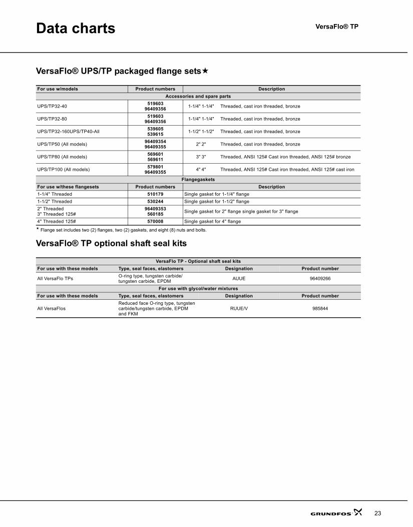
VersaFlo® UPS/TP packaged flange sets
Flange set includes two (2) flanges, two (2) gaskets, and eight (8) nuts and bolts.
VersaFlo® TP optional shaft seal kits
For use w/models Product numbers DescriptionAccessories and spare parts
UPS/TP32-40 51960396409356 1-1/4" 1-1/4" Threaded, cast iron threaded, bronze
UPS/TP32-80 51960396409356 1-1/4" 1-1/4" Threaded, cast iron threaded, bronze
UPS/TP32-160UPS/TP40-All 539605539615 1-1/2" 1-1/2" Threaded, cast iron threaded, bronze
UPS/TP50 (All models) 9640935496409355 2" 2" Threaded, cast iron threaded, bronze
UPS/TP80 (All models) 569601569611 3" 3" Threaded, ANSI 125# Cast iron threaded, ANSI 125# bronze
UPS/TP100 (All models) 57980196409355 4" 4" Threaded, ANSI 125# Cast iron threaded, ANSI 125# cast iron
FlangegasketsFor use w/these flangesets Product numbers Description1-1/4" Threaded 510179 Single gasket for 1-1/4" flange1-1/2" Threaded 530244 Single gasket for 1-1/2" flange2" Threaded3" Threaded 125#
96409353560185 Single gasket for 2" flange single gasket for 3" flange
4" Threaded 125# 570008 Single gasket for 4" flange
VersaFlo TP - Optional shaft seal kitsFor use with these models Type, seal faces, elastomers Designation Product number
All VersaFlo TPs O-ring type, tungsten carbide/tungsten carbide, EPDM AUUE 96409266
For use with glycol/water mixturesFor use with these models Type, seal faces, elastomers Designation Product number
All VersaFlosReduced face O-ring type, tungsten carbide/tungsten carbide, EPDM and FKM
RUUE/V 985844
TPVersaFlo.book Page 23 Monday, August 20, 2007 3:55 PM
VersaFlo® TP
24
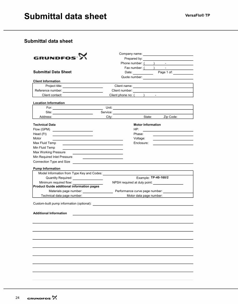
Submittal data sheet
Submittal data sheet
Company name:Prepared by:
Phone number: ( ) -Fax number: ( ) -
Submittal Data Sheet Date: Page 1 of:Quote number:
Project title: Client name:Reference number: Client number:
Client contact: Client phone no: ( ) -
For: Unit:Site: Service:
Address: City: State: Zip Code:
Technical Data Motor InformationFlow (GPM) HP:Head (Ft) Phase:Motor Voltage:Max Fluid Temp Enclosure:Min Fluid TempMax Working PressureMin Required Inlet PressureConnection Type and Size
Model Information from Type Key and Codes:Quantity Required: Example: UP-S-15-58-FC
Minimum required flow: NPSH required at duty point:Product Guide additional information pages
Materials page number: Performance curve page number:Technical data page number: Motor data page number:
Custom-built pump information (optional):
Location Information
Client Information
Additional Information
Pump Information
TP-40-160/2
TPVersaFlo.book Page 24 Monday, August 20, 2007 3:55 PM
General data VersaFlo® TP
5
Performance range, TP
Fig. 1 Performance range
TM03
619
8 44
06
TPVersaFlo.book Page 5 Monday, August 20, 2007 3:55 PM
VersaFlo® TP
4
General data
Cross reference guide: B&G, Taco and Armstrong to Grundfos
B&G Series 60&80
HPPort to
Port Length
Flange Size
Taco Series 1600
HPPort to
Port Length
Flange Size
Arm-strong HP
Port to Port
LengthFlange
SizeGrundfosModel TP HP
Port to Port
LengthFlange
Size
H-32 1/6 8-1/2" 1-1/4" 32-40 1/3 11" 1-1/4"6011 1/4 11" 1-1/4" 1600 1/4 10-1/4" 1-1/2" H-52 1/3 11-1/2" 1-1/4" 32-80 1/2 11" 1-1/4"6016 3/4 13-1/2" 1-1/2" 1614 3/4 13-1/2" 1-1/2" H-64 3/4 13-1/2" 1-1/2" 32-160 3/4 13-1/2" 1-1/2"
H-52 1/3 11-1/2" 1/4" 40-40 1/3 13-1/2" 1-1/2"H-53 1/2 11-1/2" 1-1/2" 1/2 13-1/2" 1-1/2
6013 1/2 11-1/2" 1-1/2" 1612 1/2 13-1/2" 1-1/2" H-53 1/2 11-1/2" 1-1/2" 40-80 3/4 13-1/2" 1-1/2"6015 1/2 13-1/2" 1-1/2" 1612 1/2 13-1/2" 1-1/2" H-63 1/2 13-1/2" 1-1/2" 40-80 3/4 13-1/2" 1-1/2"
H-67 1 14" 2" 40-160 3/4 11-1/2" 1-1/2"6017 1 13-1/2" 1-1/2" 1616 1-1/2 14-1/2" 2" H-65 1 13-1/2" 1-1/2" 40-240 1-1/2 13-1/2" 1-1/2"
H-53 1/2 11-1/2" 1-1/2" 50-40 1/3 14" 2"H-54 3/4 11-1/2" 2" 3/4 11-1/2" 2"
6014 3/4 11-1/2" 2" 1632 3/4 13-1/2" 2" H-54 3/4 11-1/2" 2" 50-80 3/4 11-1/2" 2"6019 1 14" 2" 1634 1 13-1/2" 2" H-67 1 14" 2" 50-160 1-1/2 14" 2"6020 1-1/2 14" 2" 1634 1 13-1/2" 2" H-68 1-1/2 14" 2" 50-160 1-1/2 14" 2"6021 2 14" 2" 10603D 3 18 3" 50-240 2 14" 2"
105028 1/2 11-1/2" 2" 80-40 1/2 19" 3"ANSI801 1-1/2 19" 3"ANSI 10603D 1-1/2 18" 3" 80-80 1-1/2 19" 3"ANSI802 3 19" 3"ANSI 10603D 3 18" 3" 80-160 3 19" 3"ANSI803 3 19" 3"ANSI 10603D 3 18" 3" 80-240 3 19" 3"ANSI
10603D 1 18" 3" 100-40 1 21" 4"ANSI806 2 21" 4"ANSI 10603D 2 18" 3" 100-80 2 21" 4"ANSI807 3 21" 4"ANSI 10603D 3 18" 3" 100-160 3 21" 4"ANSI
TPVersaFlo.book Page 4 Monday, August 20, 2007 3:55 PM
VersaFlo® TP
25
Further product documentation
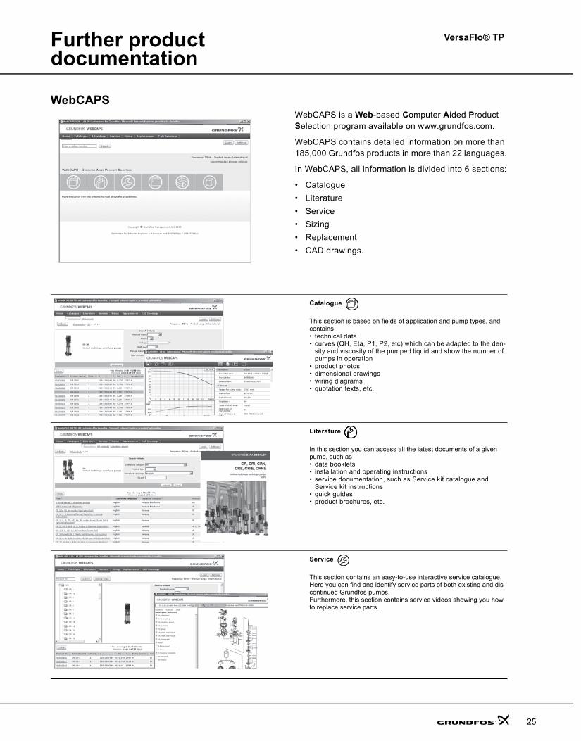
WebCAPSWebCAPS is a Web-based Computer Aided Product Selection program available on www.grundfos.com.
WebCAPS contains detailed information on more than 185,000 Grundfos products in more than 22 languages.
In WebCAPS, all information is divided into 6 sections:
• Catalogue• Literature• Service• Sizing• Replacement• CAD drawings.
Catalogue
This section is based on fields of application and pump types, and contains • technical data• curves (QH, Eta, P1, P2, etc) which can be adapted to the den-
sity and viscosity of the pumped liquid and show the number of pumps in operation
• product photos• dimensional drawings• wiring diagrams• quotation texts, etc.
Literature
In this section you can access all the latest documents of a given pump, such as• data booklets• installation and operating instructions• service documentation, such as Service kit catalogue and
Service kit instructions• quick guides• product brochures, etc.
Service
This section contains an easy-to-use interactive service catalogue. Here you can find and identify service parts of both existing and dis-continued Grundfos pumps.Furthermore, this section contains service videos showing you how to replace service parts.
TPVersaFlo.book Page 25 Monday, August 20, 2007 3:55 PM
Further product documentation
VersaFlo® TP
26
WinCAPS
Fig. 5 WinCAPS CD-ROM
WinCAPS is a Windows-based Computer Aided Product Selection program containing detailed informa-tion on more than 185,000 Grundfos products in more than 22 languages.
The program contains the same features and functions as WebCAPS, but is an ideal solution if no Internet connection is available.
WinCAPS is available on CD-ROM and updated once a year.
Sizing
This section is based on different fields of application and installa-tion examples, and gives easy step-by-step instructions in how to• select the most suitable and efficient pump for your installation• carry out advanced calculations based on energy consumption,
payback periods, load profiles, life cycle costs, etc.• analyse your selected pump via the built-in life cycle cost tool• determine the flow velocity in wastewater applications, etc.
Replacement
In this section you find a guide to selecting and comparing replace-ment data of an installed pump in order to replace the pump with a more efficient Grundfos pump. The section contains replacement data of a wide range of pumps produced by other manufacturers than Grundfos.
Based on an easy step-by-step guide, you can compare Grundfos pumps with the one you have installed on your site. When you have specified the installed pump, the guide will suggest a number of Grundfos pumps which can improve both comfort and efficiency.
CAD drawings
In this section it is possible to download 2-dimensional (2D) and 3-dimensional (3D) CAD drawings of most Grundfos pumps.
These formats are available in WebCAPS:
2-dimensional drawings:• .dxf, wireframe drawings• .dwg, wireframe drawings.
3-dimensional drawings:• .dwg, wireframe drawings (without surfaces)• .stp, solid drawings (with surfaces)• .eprt, E-drawings.
0 1
TPVersaFlo.book Page 26 Monday, August 20, 2007 3:55 PM
VersaFlo® TP
3
Mission
- to successfully develop, produce, and sell high quality pumps and pumping systems worldwide, contributing to a better quality of life and healthier environment.
• One of the 3 largest pump companies in the world• The second largest manufacturer of submersible
motors in the world• World headquarters in Denmark• North American headquarters in Kansas City -
Manufacturing in Fresno, California• 73 companies in 41 countries• More than 10 million motors and pumps produced
annually worldwide• North American companies operating in USA,
Canada and Mexico• Continuous reinvestment in growth and
development enables the company toBE responsible, THINK ahead, and INNOVATE.
Bjerringbro, Denmark
Fresno, California Olathe, Kansas
Monterrey, Mexico Allentown, Pennsylvania Oakville, Ontario
TPVersaFlo.book Page 3 Monday, August 20, 2007 3:55 PM

2
Contents
Mission
General dataCross reference guide: B&G, Taco and Armstrong to Grundfos 4Performance range, TP 5Product range, TP 6Type key, TP 6Applications 6Construction, TP 7TP technical data 7Material specification, TP 7Sectional drawing, TP 7Motor 8Pump 8Surface treatment 8Motor stool 8Pump shaft 8Coupling 8Impeller 8Shaft seal 8Space requirements 9Pumped liquids 9Liquid temperature 9List of pumped liquids 9Legend for notes in the list 9
Performance curvesTP 32-XX 12TP 40-XX 14TP 50-XX 16TP 80-XX 18TP 100-XX 20
Data chartsVersaFlo®TP 22VersaFlo® UPS/TP packaged flange sets´ 23VersaFlo® TP optional shaft seal kits 23
Submittal data sheetSubmittal data sheet 24
Further product documentationWebCAPS 25WinCAPS 26
TPVersaFlo.book Page 2 Monday, August 20, 2007 3:55 PM
27
TPVersaFlo.book Page 27 Monday, August 20, 2007 3:55 PM
GRUNDFOS Pumps Corporation 17100 West 118th TerraceOlathe, Kansas 66061Phone: +1-913-227-3400 Telefax: +1-913-227-3500
GRUNDFOS Canada Inc. 2941 Brighton Road Oakville, Ontario L6H 6C9 CanadaPhone: +1-905 829 9533 Telefax: +1-905 829 9512
Bombas GRUNDFOS de Mexico S.A. de C.V. Boulevard TLC No. 15Parque Industrial Stiva AeropuertoApodaca, N.L. Mexico 66600Phone: +52-81-8144 4000 Telefax: +52-81-8144 4010
www.grundfos.com
L-TP-PG-001 08/07USRepl. L-TP-PG-001 12/06
PRINTED IN USA Subject to alterations.
Being responsible is our foundationThinking ahead makes it possible
Innovation is the essence
TPVersaFlo.book Page 28 Monday, August 20, 2007 3:55 PM
GRUNDFOS PRODUCT GUIDE
VersaFlo®
TP circulator pumps60 Hz
TPVersaFlo.book Page 1 Monday, August 20, 2007 3:55 PM